

Page 1
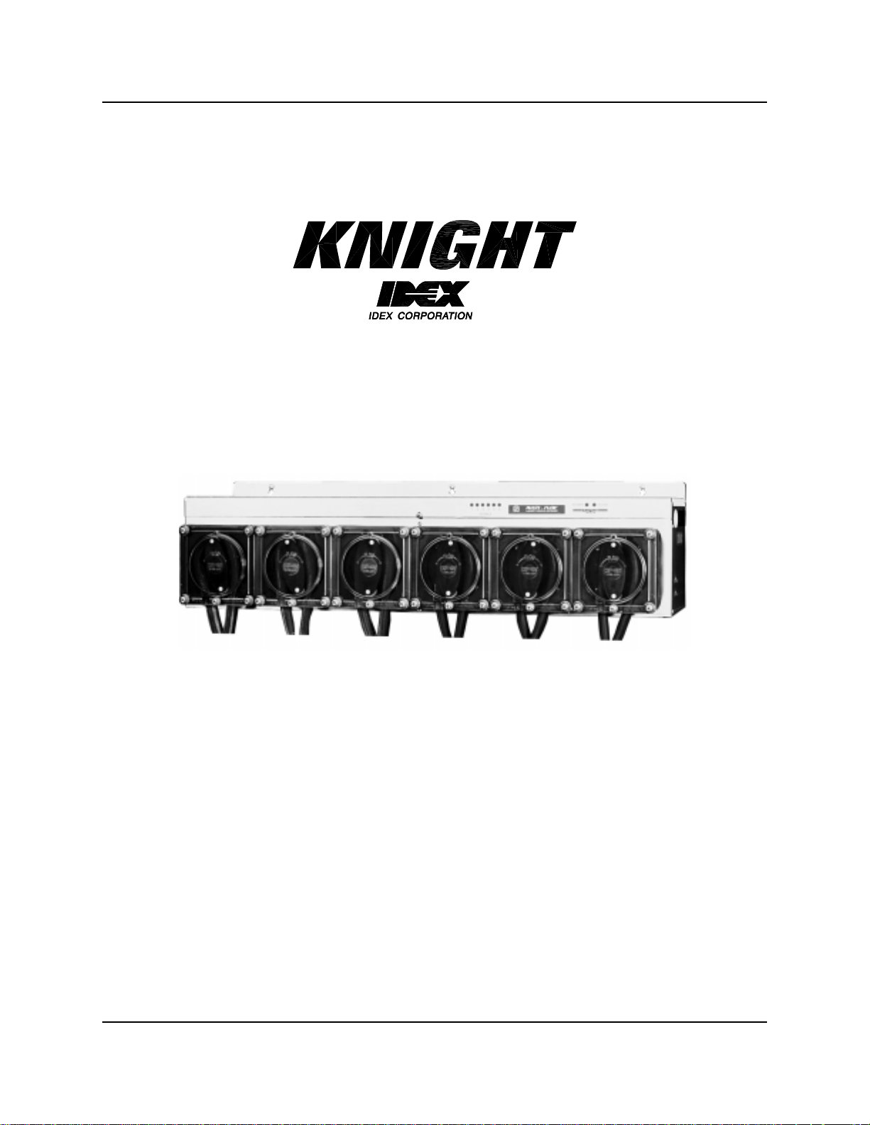
Multi-Flow
Installation & Programming
Instruction Manual
0900455 Rev: F (06/02) Page1of20
Page 2

TABLE OF CONTENTS
Menu Map.............................................................................................................3
Introduction........................................................................................................... 4
System Overview..................................................................................................4
Operation.............................................................................................................. 5
Pre-Installation .....................................................................................................6
Installation............................................................................................................6
Keypad Diagram................................................................................................... 7
Display Window....................................................................................................8
Access Codes ...................................................................................................... 8
Dispenser Setup Menu.........................................................................................9
Calibrate Pumps Menu.......................................................................................14
Formula Settings Menu ......................................................................................15
User Menu..........................................................................................................16
Data Transfer Menu............................................................................................ 17
System Wiring Diagram ..................................................................................... 18
Warranty Information.......................................................................................... 20
Knight Locations................................................................................................. 20
CAUTION: The Multi-Flow laundry system has high voltage connected to the pump circuit board. Always
disconnect main power when servicing the unit.
Page2of20 0900455 Rev: F (06/02)
Page 3

MENU MAP
1
2
DISPENSER
SETUP
CALIBRATE
PUMPS
• Clear settings
• Set bleach defeat
• Set load count pump
• Select unit of m easure
• Select delay time units
• Set signal lockout
• Set system lockout
• Set auto formula select
• Set flush mode
• Choose relay mode
• Select display type
• Change formula names
• Change main access code
• Change user access code
• Change display name
• Enable/disable pumps 7 & 8
• Drain mode
• DC pump compensation
• Signal qualify time
• Prime pumps
• Choose volume or time calibration
• Calibrate pumps
• Manually enter flow rates
3
4
5
0900455 Rev: F (06/02) Page3of20
FORMULA
SETTINGS
USER
MENU
DATA
TRANSFER
• Program formula amounts
• Program pump delay times
• Program drains
• Set multiple volume levels
• Clear load counts
• Prime pumps
• Receive setup from another dispenser
Page 4
INTRODUCTION
Please read this manual before attempting to program the dispenser — it will save you time.
The Multi-Flow dispenser features a user-friendly remote control, 16 formula capability, and available pump flow
rates of 8 oz/min, 23 oz/min, 40 oz/min, 155 oz/min and 226 oz/min. Many other outstanding features, including
integrated Flush mode, Drain mode, Relay mode and automatic programming, make this dispenser a good choice
for any small or large volume laundry.
Before connecting signal wires to the Multi-Flow, always check the schematic of the washwheel controller. These
schematics can be obtained in the instruction manual of the machine or by the machine manufacturer.
SYSTEM OVERVIEW
The Multi-Flow i s a two component system, with each component performing a specific function. The circuit board
located inside the pump housing, receives the supply signals from the washmachine. Signals are then routed to the
Remote (hand-held) Control, which is responsible for all timing and programming functions. Pump run times and
delay times are activated, based on what formula number has been selected — the pumps then run for the correct
amount of time (or volume). Accessories for installation and other optional components, such as flush manifolds, are
available. Contact your nearest Knight location for details.
Page4of20 0900455 Rev: F (06/02)
Page 5
OPERATION
NORMAL OPERATION: The system is capable of 16 user selectable formulas with each formula having unique
run times and delay times for each pump. Signals from the washer trigger the pumps, then the Multi-Flow’s
microprocessor takes control to count down delay times and run times with up to 3 individual “levels” (explained
below) for each pump. The s upervisor of the facility, or the machine operator, will select the formula using
FORMULAor FORMULAbuttons to choose the appropriate wash formula.
Programming "levels" allows a pump to inject different amounts of chemical for multiple signals to the same pump
during a formula. For example, pump 1 could inject 8 ounces of chemical on its first signal, then later inject 12
ounces of chemical on its second signal. Up to three levels are available for any pump on any formula, except for the
load count pump. ONLY 1 LEVEL CAN BE PROGRAMMED FOR THE LOAD COUNT PUMP (and any other pump
that may be signaled simultaneously with the load count pump's signal). The level feature can also be used to “skip
over” an injection. Simply do not program any volume or delay time for that level.
When a formula begins (after the RESET button has been pushed or
from the previous formula) the first signal to a pump will activate level 1. The signal has to be present for at least the
signal qualify time to be recognized. The second signal to the pump during the formula will activate level 2. The third
signal to the pump during the formula will activate level 3. Any further signals will be disregarded once level 3 has
been activated. The load count pump signal must be received to reset levels in preparation for the next formula.
DRAIN MODE OPERATION: This mode is similar to normal operation but requires only one signal source from
the washer and works by counting the number of drains during a wash c ycle. When programming the Multi-flow
dispenser for Drain Mode, each chemical pump is assigned a specific drain occurrence to inject product on. This
feature only affects how the pumps are triggered – all other functions such as pump run times, delay times, and flush
mode, will still operate in their normal fashion.
During a wash formula, each drain signal is counted and the pumps inject chemical according to the drain number
they are assigned. Drain mode is similar to normal operation, in that the pumps are programmed with run times (and
delay times if necessary) and the flush mode works the same way it does in normal operation.
The “multiple level” feature works slightly different in drain mode, because of the way drain mode counts the number
of signals to pump #1 input. If a second injection level is required, it should be programmed to inject on a later drain
number (occurrence) than the first level for that pump.
the “Load Count” pump has been triggered
• Using signal lockout is not recommended for drain mode operation.
• During a formula, when pumps are idle, the display will show the current drain count and the formula name.
• The reset button can be used to reset the drain count.
• Auto Formula Select works with drain mode, but chart mode is not recommended.
• Auto Formula Select resets drain count.
RELAY MODE OPERATION: This type of operation is typically used with a microprocessor controlled washer.
When set to relay mode, the Multi-Flow system will run its pumps as long as their respective signals are present. To
accomplish this, the system “by-passes” its run time and delay time capabilities for the chemical pumps, however
bleach defeat and flush mode are still available, with no change in the way they’re set or used. Choosing a load
count pump is still required — load counts are tallied as a cumulative number and viewed in the typical manner.
0900455 Rev: F (06/02) Page5of20
Page 6
PRE-
INSTALLATION
Before the equipment is installed, you should survey the installation site thoroughly. At the very least, your survey
should include the following:
(1) Check to m ake sure that all functions of the laundry machine are operating properly. Such functions may
include: drain valve, hot/cold water solenoids, flush down valves, water level switch, card reader or timer, and
machine motor.
(2) Check the proposed location for a 115 or 230 VAC power source.
(3) Check the signal voltage output from the laundry machine. Measure the voltage between control signal and
signal common, NOT control signal and case ground.
(4) Measure the distance(s) from chemical supply container to pump housing and from pump housing to injection
point inside the washmachine.
INSTALLATION
(1) Mount the injector in a convenient location on a wall near the supply containers — no higher than 8’ above, and
within 10’ horizontally, of the supply containers. This location is usually near the washmachine, however,
dispenser can be mounted as a remote pumping system.
(2) Mount the Remote Control using the included bracket. The Remote Control should be mounted to the front of
the washer, near the washer’s controls where the operators can access it easily.
(3) Ensure that the voltage of the system matches the main power voltage.
(4) It’s very important to measure signal voltage between the signal wire and signal common (NOT case ground).
This measurement must be taken when the washmachine is operating and when products are being called for.
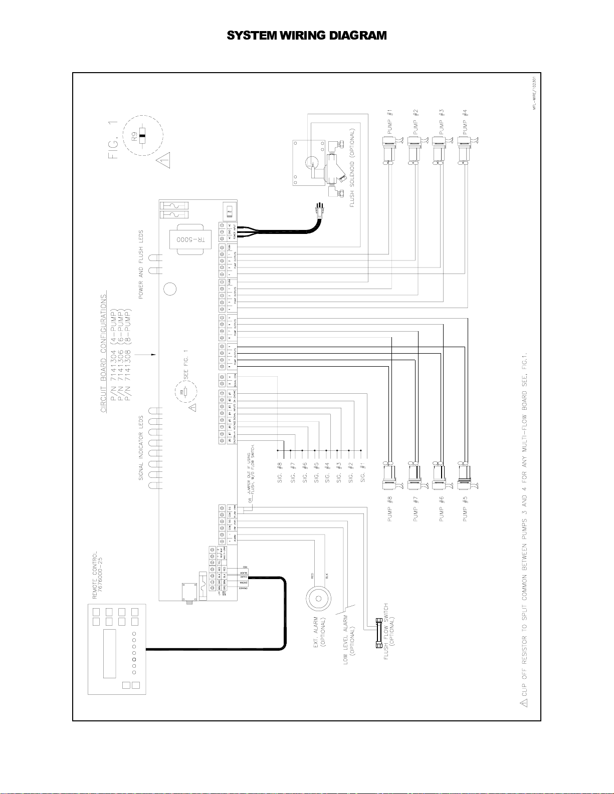
If the washmachine has 2 commons for product signals, the Multi-Flow can accommodate this by removing a
resistor to “split” commons A and B on the circuit board (see the wiring diagram on page 18 for details).
(5) BEFORE CONTINUING, DISCONNECT ALL ELECTRICAL CONNECTIONS TO THE WASHMACHINE, CARD
READER (IF SO EQUIPPED), AND INJECTOR. VERIFY THIS WITH A VOLTMETER.
(6) Run all electrical wires through suitable c onduit. Check any applicable electrical wiring codes.
(7) Inspect the wiring diagram of the washmachine and card reader (if so equipped). They are available from the
manufacturer upon request.
(8) Insert one end of the suction tube into the left side of the squeeze tube in the peristaltic pump(s).
(9) Cut suction tube to length and insert other end into the appropriate supply container using PVC pipe as a
support.
(10)Insert one end of the discharge tubing into the right side of the squeeze tube in the peristaltic pump(s).
(11)Form an anti-siphon loop (with the loop pointing “down“) with the other end of the discharge tubing and insert
the end into the supply pocket of the machine.
(12)Connect the 115 VAC or 230 VAC supply voltage to the system.
(13)Program the system via the PROGRAMMING instructions in this manual.
(14)Make any adjustments to programming which can be due to product viscosity, distance pumped, etc.
(15)Energize washmachine and card reader (if so equipped). The system should now be operational and service
free.
Page6of20 0900455 Rev: F (06/02)
Page 7
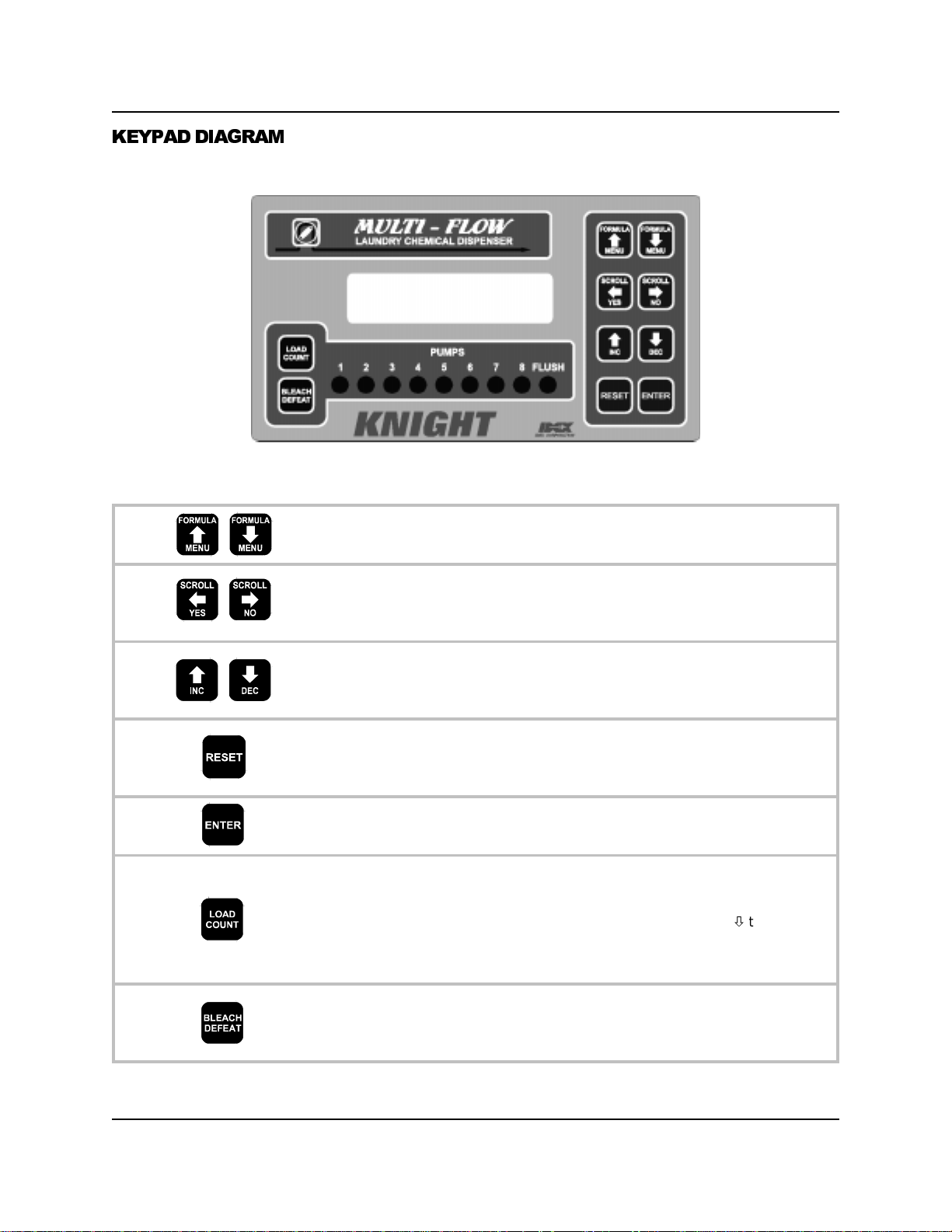
KEYPAD DIAGRAM
DISPLAY WINDOW
Allows you to choose the desired formula (unless using RELAY
mode) for operation. When programming the system, allows you to
navigate through the various menu selections.
Allows you to move (SCROLL) the cursor position left or right within
certain menu selections to choose items you wish to change. Also
acts as YES or NO when prompted for a yes/no response within a
menu selection.
INCreases or DECreases the value of a particular character (i.e.
pump number, formula name, etc). A blinking “cursor” indicates
which character will be changed by these buttons. Press repeatedly
to advance through all available letters and numbers.
Locks you out from access when finished programming. From any
selection within a menu, RESET will take you back to that menu’s
heading. Can also be used to halt pump operation and to reset the
drain count. (When using Drain Mode)
Allows you to access the system from the main (default) display.
Takes you into the menus for programming. Logs data into memory
when programming.
Shows load counts in the display window. Press once to show
load counts for all formulas, or relay mode. Press repeatedly to
advance through individual load counts for each formula (individual
load counts do not apply to relay mode). Press MENUto return to
the default display when finished viewing load counts.
Note: Load counts are cleared in menu 4.
Allows you to enable or disable the bleach defeat function. When
enabled, the “bleach defeat” pump (see DISPENSER SETUP menu
for details) will bypass operation until the load count pump is
signaled. This feature also works in relay mode, and Drain Mode.
total
0900455 Rev: F (06/02) Page7of20
Page 8
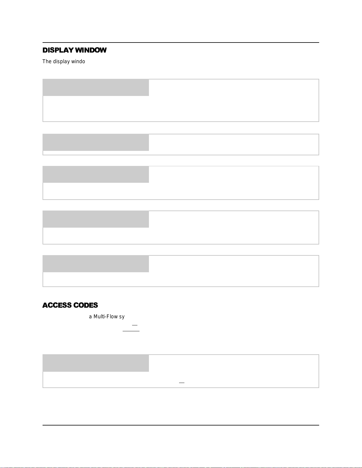
DISPLAY WINDOW
The display window shows various information about the dispenser during normal operation (i.e. when the Remote
Control is not being programmed). The following examples will illustrate:
DISPLAY NAME
FORMULA 01
FORMULA 01
P1 DLY 023 SEC
FORMULA 01
P1 VOL 017.0 OZS
DISPLAY NAME
NO BLEACH
When there is no pump activity, the display window shows the
display name and current formula (or “RELAY MODE” if used).
If using Drain Mode, the drain count will appear during the
formula and will return to the normal display when the formula is
finished.
When a pump delay time is active, the display window shows the
count-down in seconds.
When a pump is running, the display shows the count-down as a
volume (with your selected unit of m easure) or as a time, in
seconds. See DISPENSER SETUP menu for details on choosing
volume or time display.
When the bleach defeat function is enabled, the bottom line of the
display will flash alternately between NO BLEACH, and the
current formula name (or “RELAY MODE” if used). See page 7 for
details on how bleach defeat works.
LOAD COUNT
00000 LOADS
Shows total load counts for all formulas (or if using RELAY
mode). Individual formula load counts can also be viewed. See
page 7 for details on viewing load counts.
ACCESS CODES
When working with a Multi-Flow system, there are two levels of protection for the system. The “main”, or programmer
level, allows the programmer to enter all
only a few basic on-site functions without
All systems are shipped from the factory with the main and user access codes set at 000. Changing the access
codes is explained later in this manual. To get started, press ENTER (from the main display window).
ACCESS CODE 000
THEN PRESS ENTER
If the “user” access code is entered, menu availability is limited to only the functions in the USER MENU. All other
menu headings are still visible in the display window, however they cannot be entered.
of the menus and functions of the Multi-Flow system. The “user” level allows
the possibility of changing programmed information.
Use the SCROLL and INC/DEC buttons (not necessary if code
has not yet been changed from factory default of 000) to input the
access code, then press ENTER. If the “main” access code is
entered, all
functions of the system are then accessible.
Page8of20 0900455 Rev: F (06/02)
Page 9
1
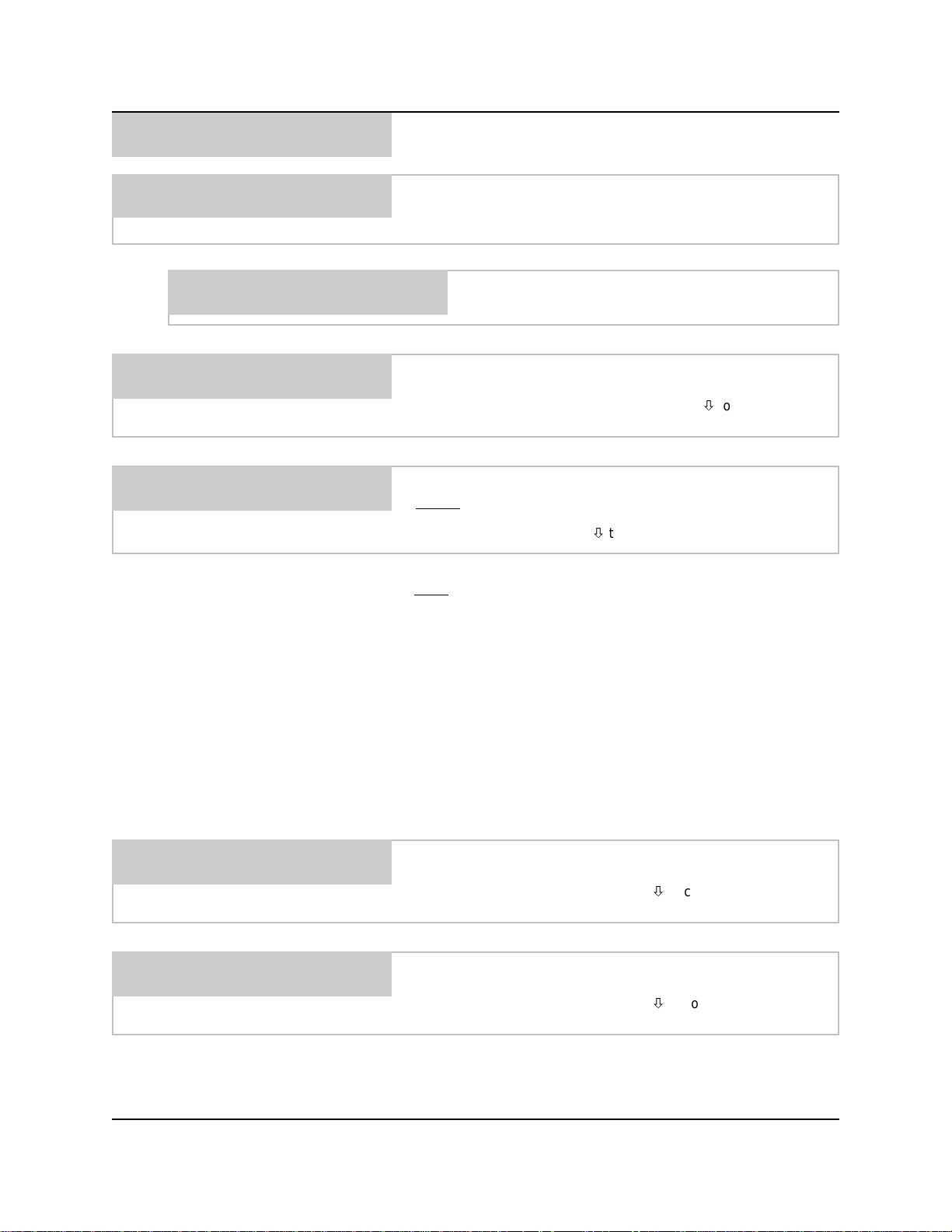
DISPENSER
SETUP
IMPORTANT: The dispenser memory must be cleared when
programming a new dispenser.
CLEAR SETTINGS ?
YES OR NO
CLEARING
MEMORY ....
BLEACH PUMP = X
INC/DEC ENTER
LOAD COUNT P= X
INC/DEC ENTER
This selection allows you to clear pump volumes, flow rates and
formula names in the dispenser and will reset the system to the
factory default setting.
If you pressed YES, this message will appear, indicating
that the dispenser memory is actively being cleared.
This selection shows which pump will be defeated if the BLEACH
DEFEAT button is pressed. Use the INC/DEC buttons to choose
the number, then press ENTER. Press MENUto continue.
This selection shows which pump is being used to count loads.
Always
signal. Use the INC/DEC buttons to choose the number, then
press ENTER. Press MENUto continue.
IMPORTANT: The load count pump must receive a signal on
every
load count pump will not actually dispense chemical for the
formula selected).
enter the last pump in the system that will receive a
washcycle for the system to operate correctly (even if the
UNITS = US
INC/DEC
DELAY UNITS=SEC
INC/DEC
When the load count pump receives a signal, the load counter is
incremented as well as resetting bleach defeat, formula levels,
and signal lockout in preparation for the next washcycle.
This setting is critical when using Drain Mode to maintain proper
injection sequence. Normally you will set the load count pump to
correspond with the last drain signal that will be received during
the formula, however there may be additional drain signals that
occur after the last pump has injected. In this situation, a fictitious
pump can be assigned to act as a load count pump.
This selection allows you to choose between US, Metric, or
Imperial units of measure. Use the INC/DEC buttons to choose
the desired setting, then press MENUto continue.
This selection allows you to choose seconds or minutes as the
delay time unit of measure. Use the INC/DEC buttons to choose
the desired setting, then press MENUto continue.
Some injections only need to be delayed for a few seconds while
others need much longer times. Choose the setting best suited for
your particular installation.
0900455 Rev: F (06/02) Page9of20
Page 10

SIG LOCKOUT=OFF
INC/DEC
This selection allows you to select whether you want “erroneous”
signals to be ignored by the system. Typically, erroneous signals
are generated by some washers when a water level goes low and
a fill valve activates. Use the INC/DEC buttons to choose the
desired setting, then press MENUto continue.
The signal lockout feature is by-passed when the system is
operating in relay mode, as the pumps are directly controlled by
the signals from the washer’s controller.
SIG LOCKOUT TIME = 00
INC/DEC ENTER
SYS LOCKOUT = 00
INC/DEC ENTER
AFS = ENABLED
INC/DEC
AFSMODE=MICRO
INC/DEC
This selection sets the time (in minutes) that signal lockout will
disregard incoming supply signals. The setting applies to all
pumps except the load count pump. Use the SCROLL and INC/
DEC buttons to choose a lockout time between 0 and 99 minutes,
then press ENTER. Press MENUto continue.
This selection sets the time (in minutes) that the system will be
“locked-out” to all incoming supply signals. The lock-out time is
started by a signal to the load count pump. Use the SCROLL and
INC/DEC buttons to choose a lockout time between 0 and 99
minutes, then press ENTER. Press MENUto continue.
This selection enables the Automatic Formula Select feature. This
feature allows the washwheel controller to send signals to the
Multi-Flow dispenser and automatically select the correct wash
formula. Washroom personnel no longer select formulas, thereby
eliminating potential mistakes. Use the INC/DEC buttons to make
your choice, then press MENUto continue.
This selection allows you to choose which AFS mode will be used
to select formulas. See the notes below for details on how the
modes work. Use the INC/DEC buttons to make your choice, then
press MENUto continue.
MICRO: Typically used with microprocessor c ontrolled washers
that can send a signal of exact duration to the Multi-Flow unit. The
Multi-Flow interprets the duration of the signal as the formula
number requested, based on the AFS SIGNAL TIME explained in
the next menu selection.
CHART: Typically used with card-reader type machines. Uses a
combination of signals to pick the formula in a “binary” numbering
format. The auto formula select signal must be applied for a
minimum of 30 seconds.
Page 10 of 20 0900455 Rev: F (06/02)
Page 11
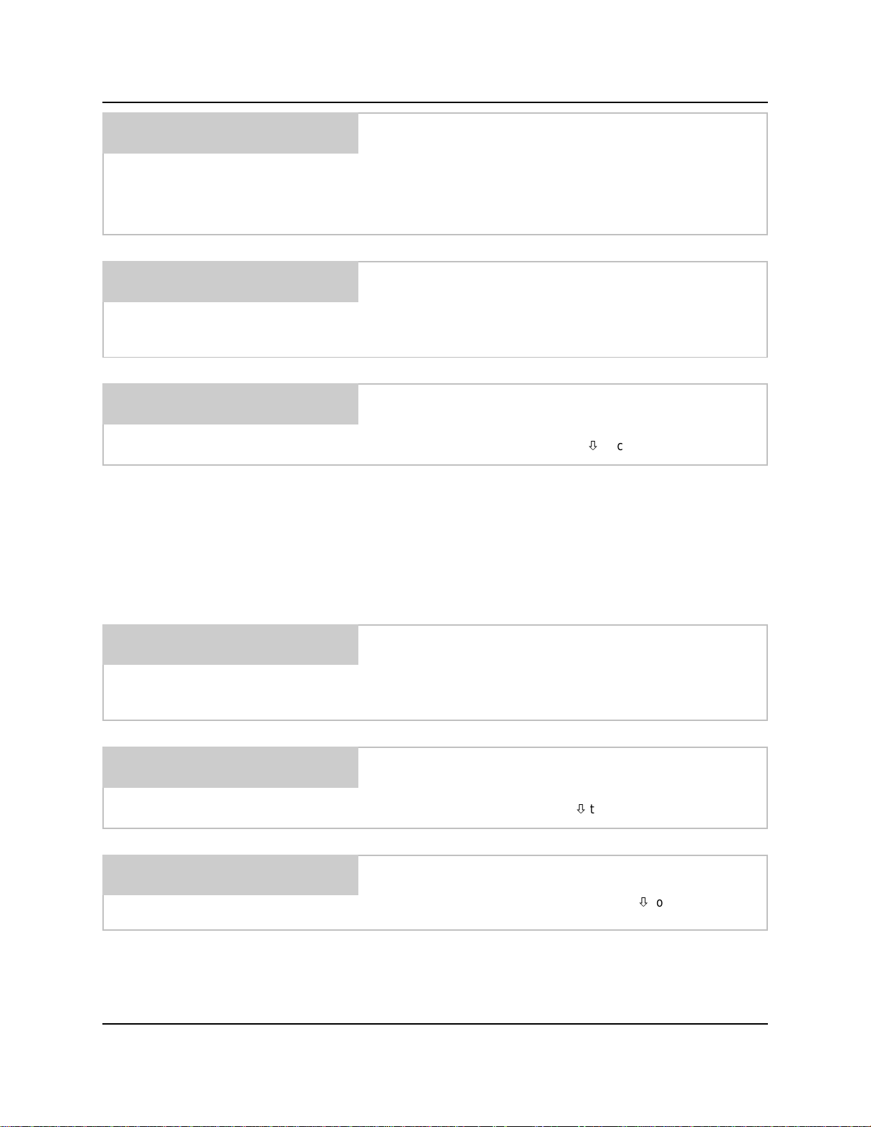
AFS SIG TIME = 1
INC/DEC
This selection is used with AFS micro mode to establish a time
“increment” for selecting formulas. The signal duration will be
divided by the number selected to choose the formula. The
available signal time increments (in seconds) are 1, 2, or 5.
Example: If AFS signal time is set for 2, a 20 second signal from
the washer would choose formula 10 on the Multi-Flow.
AFSPUMP=0
INC/DEC ENTER
FLUSH = DISABLED
INC/DEC
FLUSH TIME = 000
INC/DEC ENTER
This selection sets which pump signal input will be used for the
auto formula select feature. Choose an “unused” pump input (one
that is not used to trigger a chemical injection).
NOTE: Chart mode can only use pump 6, 7, or 8 as AFS pump.
This selection allows you to select if you want to use flush mode.
Use the INC/DEC buttons to choose if the flush will happen
any pump,
after
any pump, or if this feature will be disabled (off).
with
Make a selection, then press MENUto continue.
If you chose “with”, the flush will activate simultaneously during
the operation of any pump(s). When the pumps finish running, the
flush will remain active and begin counting down it’s own
programmed run time.
If you chose “after”, the flush will not activate until the pumps
finish running, then the flush will then begin counting down it’s
own programmed run time.
This selection allows you to set the flush time for all formulas, or if
using RELAY MODE. To set the flush time (in seconds) use the
SCROLL and INC/DEC buttons to establish the desired time, then
press ENTER. This is the amount of time that the flush will stay
active when a pump finishes injecting.
RELAYMODE=OFF
INC/DEC
This selection allows you to select if you want to use relay mode.
See the operation section of this manual for details on how the
relay mode works. Use the INC/DEC buttons to choose the
desired setting, then press MENUto continue.
DISPLAY = TIME
INC/DEC
This selection allows you to choose how the main display will
show pump activity counting down. Use the INC/DEC buttons to
choose “time” or “volume”, then press MENUto continue.
0900455 Rev: F (06/02) Page 11 of 20
Page 12
FORMULA 01
FORMULA 01
This selection allows you to customize formula names (up to 14
characters). Use the SCROLL and INC/DEC buttons to choose
the formula number on the top line, then press ENTER ... the
current name of that formula will appear on the bottom line. Press
SCROLL to move the cursor down to the bottom line, then use
the SCROLL and INC/DEC buttons to establish a formula
name ... press ENTER to log the data into memory. Repeat this
step for other formulas, then press MENUto continue.
ACCESS CODE=000
INC/DEC ENTER
USER ACCESS CODE
=000 INC/DEC ENT
DISPLAY NAME
PMP 7 & 8 = DISABLE
INC/DEC
This selection allows the “main” access code to be changed. Use
the SCROLL and INC/DEC buttons to establish the new code
number, then press ENTER to log the data into memory. Press
MENUto continue.
This selection allows the “user” access code to be changed. Use
the SCROLL and INC/DEC buttons to establish the new code
number, then press ENTER to log the data into memory. Press
MENUto continue.
If access codes are changed, keep a record of the changes in a
safe place, in the event that access codes are forgotten. If the
record of code changes becomes misplaced, contact Knight.
This selection allows you to change the display name that shows
in the window of the Remote Control (up to 14 characters). Press
SCROLL to move the blinking cursor down to the bottom line,
then use the SCROLL and INC/DEC buttons to establish the new
display name ... press ENTER to log the data into memory.
Check the dispenser circuit board to determine if there are output
connections for pumps 7 and 8. If there is, choose ENABLE using
the INC/DEC buttons. If the circuit board does not have
connections for pumps 7 and 8, make sure this menu selection is
set to DISABLE.
DRAIN MODE = ON
INC / DEC
This selection allows you to turn the drain mode ON or OFF. Use
INC/DEC to make your selection, then press MENU
to
continue.
DRAIN SIG = NORMAL
INC / DEC
This selection allows you to select if the drain signal is to be
NORMAL or INVERTED. Use INC/DEC to make your selection,
then press MENUto continue.
Page 12 of 20 0900455 Rev: F (06/02)
Page 13
DC PUMP COMP=OFF
INC / DEC
This feature is designed for applications where the Multi-Flow
remote control is used with an On-Premise (OP) or On-Premise
Plus (OPP) pump unit. It allows the Multi-Flow control to
compensate for multiple pumps running simultaneously. This
overcomes the slight drop in pump speed, and ensures that the
programmed dosages are properly injected.
This feature is available for use with normal operation or drain
mode only (not used with relay mode). It is not necessary to reprogram the dispenser, and all other pump functions will still work
in their normal manner. The software will automatically extend the
run time of the pumps in the following ways:
1 pump running — no effect, the pump will run its normal time.
2 pumps running — the run time counting down on the display
will appear normal, but the
actual
time that the pumps run will be
increased by 10%.
3 pumps running — the run time counting down on the display
will appear normal, but the
actual
time that the pumps run will be
increased by 20%.
This feature only affects the pumps while they are running
simultaneously. For example, if two pumps begin running at the
same time, but one finishes before the other, then the pump that
is still running will finish its remaining time without compensation.
Use INC/DEC to turn this feature on or off, then press MENUto
continue.
SIGNAL QUALIFY
=005 SEC (1-255)
This selection allows you to determine the appropriate length of a
valid supply s ignal from the washer. Supply signals must be of a
duration that matches the minimum setting to activate any pump
in the system, or start a pump delay.
Use the SCROLL and INC/DEC buttons to choose a signal qualify
time of 1 to 255 seconds, then press ENTER. Press MENUto
continue.
NOTE: The factory default setting is 5 seconds.
0900455 Rev: F (06/02) Page 13 of 20
Page 14
2
CALIBRATE
PUMPS
PRIMEPUMP1
ENT = START/STOP
CALIBRATE=VOLUME
INC/DEC ENTER
CALIBRATE P 1
INC/DEC
This selection allows you to prime pumps. Use INC/DEC to
choose the pump number, then press ENTER to start pump.
Press ENTER again to stop pump. Press MENUto continue.
This selection allows you to choose “volume” or “time” pump
calibration — see the following notes. Use INC/DEC to make your
selection, then press ENTER. Press MENUto continue.
VOLUME: Pump flow rates are set by actually running the pump
and dispensing product. This allows the system to calculate true
flow rates. Use a large container with volume markings, such as a
beaker or graduated cylinder, for the calibration steps below.
TIME: Setting pump flow rates is not necessary. Pumps simply run
for a specific time as programmed in each formula. See the
FORMULA SETTINGS menu for more details.
This selection appears if you chose “volume” calibration.
Choose the pump you wish to calibrate using the INC/
DEC buttons, then press MENUto continue.
DISPENSE 000 OZS
ENT = START/STOP
FLOW RATES/MIN.
P-1 =000.0 OZS
Use SCROLL and INC/DEC to set a volume amount you
wish to calibrate with (4 oz, 6 oz, 12 oz, etc). Ensure that
the pump is primed, then position your container below
the pump output. Press ENTER to start the pump. When
the container is filled to the volume you specified, press
ENTER again to stop the pump. The flow rate is
automatically calculated and you will see the following...
To view existing flow rates, use INC/DEC to choose the
pump (ensure that the “cursor” is blinking on the pump
number) then press ENTER . If you know the exact flow
rate and want to enter it manually, use SCROLL and
INC/DEC to establish the volume (ensure that the
“cursor” is blinking on the volume) and press ENTER.
NOTE: The cursor position determines whether data is
read fromorwritten to
Press MENUto calibrate other pumps. If desired, you can get to
the above display without having to run pumps by simply pressing
MENUwhen entering CALIBRATE PUMPS menu.
memory.
Page 14 of 20 0900455 Rev: F (06/02)
Page 15
3
FORMULA
SETTINGS
NOTE: Programming formula settings is not necessary for “relay
mode” operation (pumps run for as long as their signal is present
in RELAY MODE). See Relay Mode section for more details.
If you chose VOLUME (from CALIBRATE PUMPS menu)...
FORM O1 L 1 P 1
V 000.0 OZS D000
FORM 01 L 1 P 1
ENT = START/STOP
FORM 01 L1 P1
T 000 SEC D000
To view existing data, use the SCROLL and INC/DEC buttons to
choose the desired formula/level/pump, then press ENTER while
the blinking cursor is on the top line. To input new data, repeat
the previous step, then use the SCROLL and INC/DEC buttons to
establish the volume and delay time, then press ENTER while the
cursor is on the bottom line. Press MENUto continue.
If you chose TIME (from CALIBRATE PUMPS menu)...
Use the SCROLL and INC/DEC buttons to choose the formula,
level, and pump number, then press ENTER to start the pump.
When the desired amount of product has been dispensed, press
ENTER again to stop the pump. The run time is tracked
automatically and the display below will appear…
NOTE: You can get to the following display without
pumps by pressing MENUfrom this menu selection.
To view other formula/level/pump information, use the SCROLL
and INC/DEC buttons to pick your choice, then press ENTER
while the blinking cursor is still on the top line. If you wish to
change the data, or input it without running pumps, repeat the
previous step, then use the SCROLL and INC/DEC buttons to
establish the run time and delay time, then press ENTER while
the blinking cursor is on the bottom line.
having to run
MAX VOLUME
IS 255 SEC
MAX DELAY
IS 255 SEC
FORM 01 L 1 P1
DRAIN COUNT = 000
0900455 Rev: F (06/02) Page 15 of 20
This selection is for use with drain mode only
enter the drain assignment for each pump and formula. Use the
SCROLL and INC/DEC buttons to choose formula, level, and
pump numbers, then use the SCROLL button to move the cursor
to the bottom line to change the drain assignment. Then press
ENTER while the blinking cursor is still on the bottom line. Repeat
this for each pump on every level in each formula used.
If this message appears, it indicates an attempt to
program a volume that exceeds the run time limit of 255
seconds (as calculated by the flow rate of the pump).
If this message appears, it indicates an attempt to
program a delay time that exceeds 255 seconds (or
minutes, as selected in the DISPENSER SETUP menu).
and allows you to
Page 16
4
USER
MENU
This menu is always available if the “main” access code is used,
however, this is the ONLY menu that is available if the “user”
access code is used.
CLEAR LOAD COUNT
YES OR NO
CLEARING
LOAD COUNTS
PRIMEPUMP1
ENT = START/STOP
This selection allows you to clear the load count memory.
If you pressed YES, this message will appear, indicating
that the all load counts are actively being cleared.
This selection allows you to prime pumps. Use INC/DEC to
choose the pump number, then press ENTER to start pump.
Press ENTER again to stop pump. Press MENUto continue.
Page 16 of 20 0900455 Rev: F (06/02)
Page 17
5
DATA
TRANSFER
This menu allows you to copy all dispenser settings from another
Multi-Flow Remote Control. The Remote Controls must be
connected together with a network cable. Shut off the power to
both dispensers before connecting the stereo jack cable. Once the
cable is firmly connected to the stereo jacks on both Remote
Controls, power may then be re-applied.
NOTE: You can perform a data transfer with only one of the
dispensers powered up (i.e. when carrying a Remote Control
that’s disconnected from its dispenser for portability). Be sure to
shut off the dispenser before connecting the Remote Controls.
Once the c able is firmly connected to the stereo jacks on both
Remote Controls, power may then be re-applied.
RECEIVE SETUP
PRESS: YES OR NO
RECEIVING
SETUP
This selection allows you to receive the programmed information
from the other Multi-Flow Remote Control.
If you pressed YES, this message will appear, indicating
that the setup is being received from the other
dispenser. When the process is finished, you will be
returned to the menu heading.
0900455 Rev: F (06/02) Page 17 of 20
Page 18
SYSTEM WIRING DIAGRAM
Page 18 of 20 0900455 Rev: F (06/02)
Page 19

NOTES
0900455 Rev: F (06/02) Page 19 of 20
Page 20
DISCLAIMER
Knight Inc. does not accept responsibility for the mishandling, misuse, or non-performance of the described items
when used for purposes other than those specified in the instructions. For hazardous materials information consult
label, MSDS, or Knight Inc.
WARRANTY
All Knight controls and pump systems are warranted against defects in material and workmanship for a period of
ONE year. All electronic c ontrol boards have a TWO year warranty. Warranty applies only to the replacement or
repair of such parts when returned to factory with a Knight Return Authorization (KRA) number, freight prepaid, and
found to be defective upon factory authorized inspection. Bearings and pump s eals or rubber and synthetic rubber
parts such as “O” rings, diaphragms, squeeze tubing, and gaskets are considered expendable and are not covered
under warranty. Warranty does not cover liability resulting from performance of this equipment nor the labor to
replace this equipment. Product abuse or misuse voids warranty.
KNIGHT INC.
World Headquarters: 20531 Crescent Bay Drive, Lake Forest, CA 92630-8825 (USA) TEL: 949-595-4800, FAX: 949-595-4801, www.knightequip.com
Atlanta Branch:
415 Gees Mill Business
Court NE, Suite 200
Conyers, GA 30013 USA
TEL: 770-760-8777
FAX: 770-761-0199
Toronto Branch:
2880 Argentia Road, Unit 6
Mississauga, Ontario
L5N 7X8 Canada
TEL: 905-542-2333
FAX: 905-542-1536
London Branch:
#15 Brunel Centre
Newton Road, Crawley
West Sussex UK RH10 9TU
TEL: 44-1293-615570
FAX: 44-1293-615585
A Unit of IDEX Corporation
Sydney Branch:
Unit 28, 317-321
Woodpark Rd., Smithfield
NSW Australia 2164
TEL: 61-29-725-2588
FAX: 61-29-725-2025
AmsterdamBranch:
Marssteden 68
7547 TD Enschede
The Netherlands
TEL: 31-53-428-58-00
FAX: 31-53-428-58-09
Spain Branch:
Port Ginesta, Local 210
08860 Sitges
Barcelona Spain
TEL: 34-936-342-130
FAX: 34-936-643-477
Page 20 of 20 0900455 Rev: F (06/02)
 Loading...