

Page 1
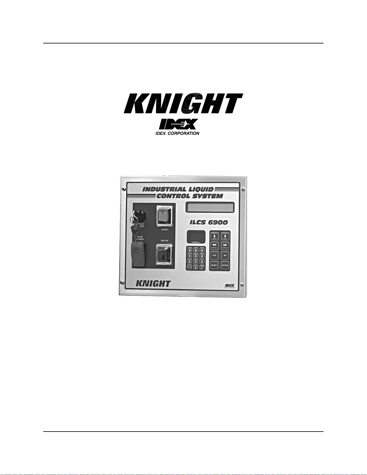
ILCS Version 2.0 System
Programming Manual
0900511 Rev: D (04/03) Page1of20
Page 2

TABLE OF CONTENTS
Menu Map.............................................................................................................3
Control Panel Diagram.........................................................................................4
Introduction........................................................................................................... 5
Access Codes ...................................................................................................... 5
Memory Functions................................................................................................6
Setup Routines.....................................................................................................9
Report Setup Routines....................................................................................... 11
Maintenance Schedule.......................................................................................15
Programming Routines....................................................................................... 16
Operation............................................................................................................ 18
Warranty Information..........................................................................................20
Knight Locations.................................................................................................20
Page2of20 0900511 Rev: D (04/03)
Page 3

MENU MAP
*** DISPENSER ***
1
2
3
MEMORY FUNCTIONS
*** DISPENSER ***
SETUP ROUTINES
*** DISPENSER ***
REPORT SETUP ROUTINES
• Clear pump volumes
• Clear sum/cycle report
• Clear batch count
• Load factory defaults
• Set external memory module ID
• Change dispenser ID #
• Change main access code
• Set date and time
• Set unit of m easure
• Set flush time
• Set simultaneous pump operation
• Change user access code
• Change user password
• Change formula access
• Change report name
• Change chemical names
• Change product costs
• Change formula names
• Set shift times
• Set operating zone
*** DISPENSER ***
4
MAINTENANCE SCHEDULE
*** DISPENSER ***
5
PROGRAMMING ROUTINES
• Date dispenser installed
• Date squeeze tube last changed
• Date squeeze tube last lubed
• Prime pumps
• Calibrate pumps
• Manually enter pump flow rates
• Program formulas
0900511 Rev: D (04/03) Page3of20
Page 4
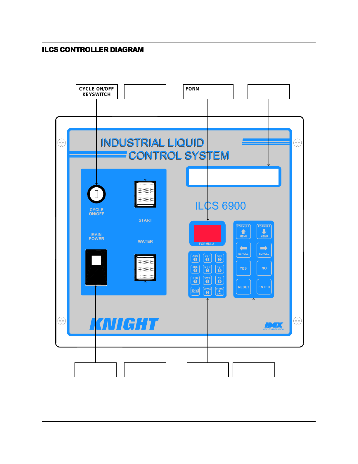
ILCS CONTROLLER DIAGRAM
CYCLE ON/OFF
KEYSWITCH
CYCLE START
BUTTON
FORMULA NUMBER
DISPLAY
PROGRAMMING
DISPLAY
MAINPOWER
ON/OFF SWITCH
Page4of20 0900511 Rev: D (04/03)
WATER FLUSH
PUSH-BUTTON
ALPHANUMERIC
KEYPAD
PROGRAMMING
KEYPAD
Page 5

MOVING THROUGH THE MENUS
ILCS programming is done through the use of menu selections. Any menu can be entered by pressing the ENTER
button, or exited by pressing RESET (or in some cases MENUor). Its that simple! Each of the main menu
headings give an idea of what information can be found, entered, or changed. Within each main menu selection are
several screen “prompts” that walk you through the complete programming process step-by-step.
Below is an example
commonly referred to as the
FORMULA 01
DATE 05/11 TIME 14:32:54
of the main display when you are not in the programming menus. The main display is more
default display
, and appears when the system is in normal operating mode.
The default display shows the present formula name on the top
line. The bottom line of the display will alternate between date/
time and the message ENTER USER PASSWORD.
The “user password” should not be confused with systems access
code. User passwords allow multiple persons to operate the
system for dispensing chemicals, whereas the access code
allows entry into the menus for programming.
From the default display, you must enter the main access code
(following) to begin programming.
ACCESS CODES
The ILCS system has two access codes for protection:
• The "main" access code, allows entry into ALL of the menus and functions of the system.
• The "user" access code allows printing reports with WinReporter PC software, without the ability of changing
programmed information.
Systems are shipped from the factory with both access codes set to zero. Only a person with the "main" access
code can change the "user" access code. (changing codes is explained later in this manual). If desired the two
access codes can be the same, however the user will then have access to ALL of the functions of the system,
including the ability of changing programmed information.
TO PROGRAM DISPENSER
ENTER ACCESS CODE
THEN PRESS ENTER
PRESS “ENTER” ...
From the default display shown above, press the ENTER button.
The screen at left should appear. If the screen at left does not
appear, wait 2 seconds, press RESET, then press ENTER.
When you see the screen at left, type in the access code and
press ENTER. Remember, for a new system, the access code will
be zero (until you change it later).
Follow the programming steps for each section, starting on the
next page.
IMPORTANT NOTES:
• Leading zeroes on main access code, user access code, and user passwords, are not required to be entered. For
example, a user password of “010” can be typed in as “10”, then press ENTER.
• Its recommended to clear pump volumes, sum/cycle report, and batch count, then loading factory defaults prior to
initial programming of formulas. See MEMORY FUNCTIONS [menu 1] for details.
• If at any time you get lost in the program ming and are not sure what to do, press the RESET button until the
section menu heading appears, then proceed.
0900511 Rev: D (04/03) Page5of20
Page 6
*** DISPENSER ***
1
MEMORY FUNCTIONS
• Clear pump volumes
• Clear sum/cycle report
• Clear batch count
• Load factory defaults
• Set external memory module ID
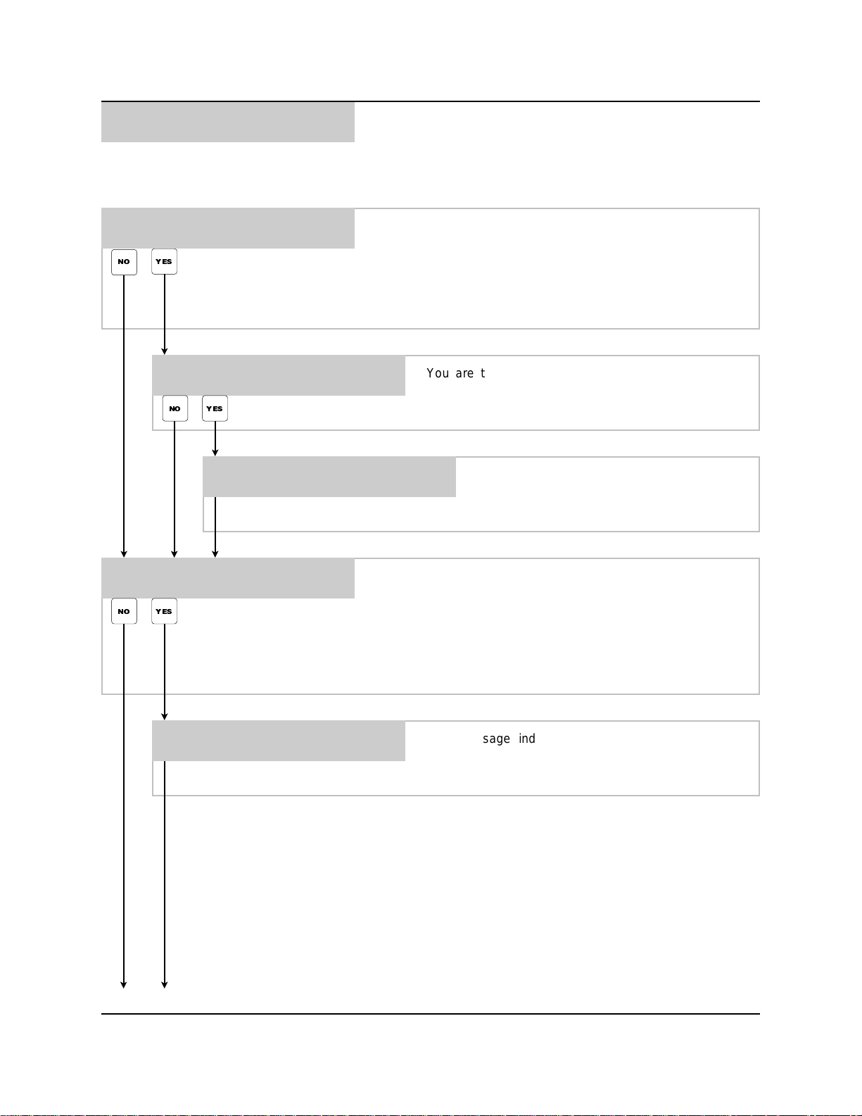
CLEAR PUMP VOLUMES ?
PRESS: YES OR NO
NO YES
ARE YOU SURE ?
PRESS: YES OR NO
YES NO
PUMP VOLUMES
CLEAR SUM/CYCLE REPORT ?
PRESS: YES OR NO
NO YES
CLEARING ALL
This menu selection is used to do the following:
– All formula volume amounts are set to zero
– All pump flow rates and product costs are set to zero
Press YES to begin clearing, or press NO to move on to the next
menu selection without clearing.
You are then asked if you really do want to use this
command. Press YES if you are sure, or press NO to
move on to the next menu selection without clearing.
This message indicates that the clearing
process is active. When the process is
complete, the next menu item will appear.
This menu selection is used to c lear the summary and cycle
report memory (also known as the batch tracking report). Press
YES to begin clearing, or press NO to move on to the next menu
selection without clearing.
GO TO NEXT PAGE
CLEARING ALL SUM/CYCLE
INFORMATION
NOTE: This will only clear the time stamps in the basic system
memory. To clear the time stamps in the external memory
module, you must use the ILCS WinReporter PC software.
This message indicates that the clearing process is
active. When the process is complete, the next menu
item will appear.
Page6of20 0900511 Rev: D (04/03)
Page 7
*** DISPENSER ***
1
MEMORY FUNCTIONS
• Continued
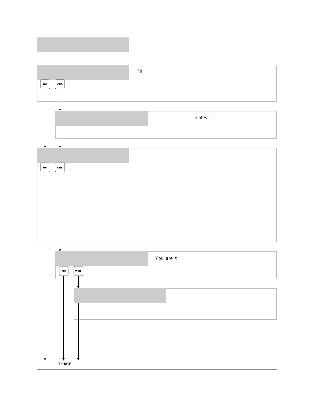
CLEAR BATCH COUNT ?
PRESS: YES OR NO
NO YES
CLEARING BATCH COUNT
LOAD FACTORY DEFAULTS ?
PRESS: YES OR NO
NO YES
This menu selection is used to zero out the batch count (this is
the digital counter that appears on the screen when pressing the
BATCH COUNT button on the control panel). Press YES to begin
clearing, or press NO to move on to the next menu selection
without clearing.
This message indicates that the clearing process is
active. When the process is complete, the next menu
item will appear.
This menu selection is used to load factory default settings:
– Unit of measure is set to US
– Flush time is set to 10 seconds / drain after set to 2 seconds
– Simultaneous pump setting is turned OFF
– All user passwords are set to zero / user names are reset
– Formula access is set to enable for all users on all formulas
– Report name is cleared (blanked out)
– Chemical names and formula names are reset
– Shift start times are reset: 1 = 06:00 / 2 = 11:00 / 3 = 17:00
– Operating zone is set for 00:00 to 24:00
– Maintenance schedule dates are set to zero
GO TO NEXT PAGE
ARE YOU SURE ?
PRESS: YES OR NO
YES NO
CLEARING SETUP
*** PLEASE STAND BY ***
Press YES to begin loading factory defaults (also known as
“clearing the setup“) or press NO to move on to the next menu
selection without loading factory defaults.
You are then asked if you really do want to use this
command. Press YES if you are sure, or press NO to
move on to the next menu selection without loading.
This message indicates that the clearing
process is active (factory defaults are being
loaded at this point). When the process is
complete, the next menu item will appear.
0900511 Rev: D (04/03) Page7of20
Page 8
*** DISPENSER ***
1
MEMORY FUNCTIONS
• Continued
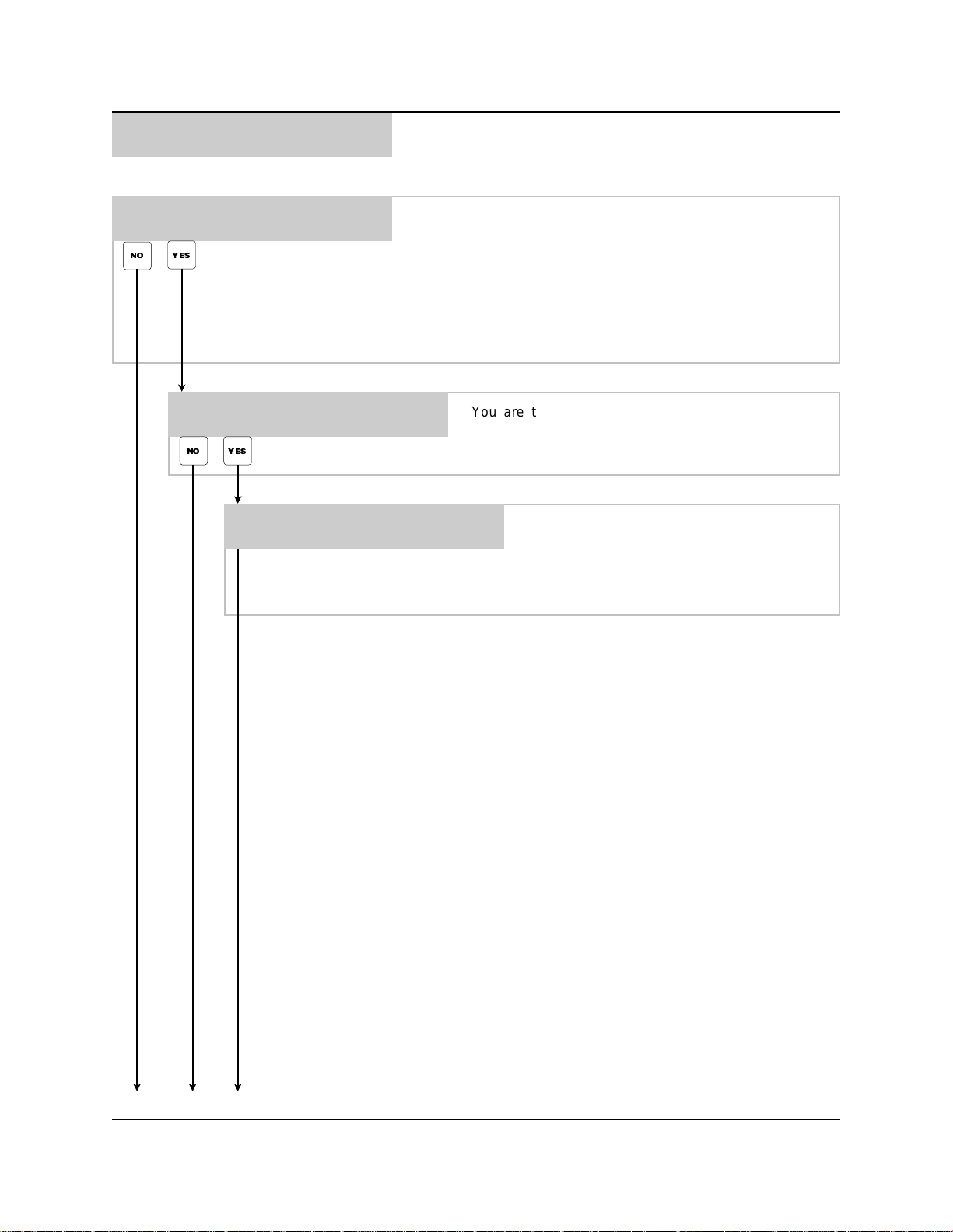
SET EXT MEM MODULE ID ?
PRESS: YES OR NO
NO YES
ARE YOU SURE ?
PRESS: YES OR NO
YES NO
SETTING EXT MEM MODULE
*** ID TO CURRENT ID ***
This menu selection is used to set the ID number of the external
memory module to match the dispenser‘s ID.
Press NO for a new installation, or if the external memory module
ID had been set previously.
Press YES if you have changed the dispenser ID in menu #2. Be
sure the unit is not be multi-linked (with other dispensers) while
performing this step.
You are then asked if you really do want to use this
command. Press YES if you are sure, or press NO to
return back to the menu heading without setting.
This message indicates that the ID number of
the external memory module is being set to the
dispenser‘s current ID number. When the
process is complete, you will be returned back
to the menu heading.
MEMORY FUNCTIONS MENU HEADING
Page8of20 0900511 Rev: D (04/03)
Page 9
*** DISPENSER ***
2
SETUP ROUTINES
• Change dispenser ID #
• Change main access code
• Set date and time
• Set unit of m easure
• Set flush time
• Set simultaneous pump operation
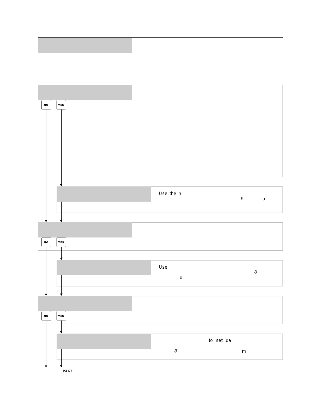
CHANGE DISPENSER ID# ?
PRESS: YES OR NO
NO YES
NEW DISPENSER ID# 00
THEN PRESS ENTER
CHANGE MAIN ACCESS CODE ?
PRESS: YES OR NO
NO YES
This menu selection allows you to change the dispenser ID
number. The dispenser ID number has two purposes:
(1) It is printed in the upper-left corner of reports to identify which
dispenser the report came from. This can be helpful when more
than one dispenser is installed at the location.
(2) When running ILCS WinReporter (optional), the ID number is
used for “logging on” to the dispenser from the computer. Several
dispensers can be connected together in a daisy chain format
known as “multilinking”. If using multilink, be sure each dispenser
has its own separate ID number before attempting to logon.
Press YES to invoke the command, or press NO to move on to
the next menu selection. If the ID number is changed, you must
set the ID of the external memory module in menu #1.
Use the number buttons to enter a 2-digit ID number,
then press ENTER. Press the MENUbutton to move
on to the next menu selection.
This menu selection allows you to change the main access code.
Press YES to invoke the command, or press NO to move on to
the next menu selection.
MAIN ACCESS CODE = 000
THEN PRESS ENTER
Use the number buttons to enter a 3-digit main access
code, then press ENTER. Press the MENUbutton to
move on to the next menu selection.
SET DATE & TIME ?
PRESS: YES OR NO
NO YES
HOUR 00 MINUTE 00
MONTH 00 DAY 00 YR 00
This menu selection allows you to set the time and date. Press
YES to invoke the command, or press NO to move on to the next
menu selection.
Use number buttons to set date and time (military
format, 13:00 = 1:00 PM) then press ENTER. Press the
MENUbutton to move on to the next menu selection.
GO TO NEXT PAGE
0900511 Rev: D (04/03) Page9of20
Page 10
*** DISPENSER ***
2
SETUP ROUTINES
• Continued
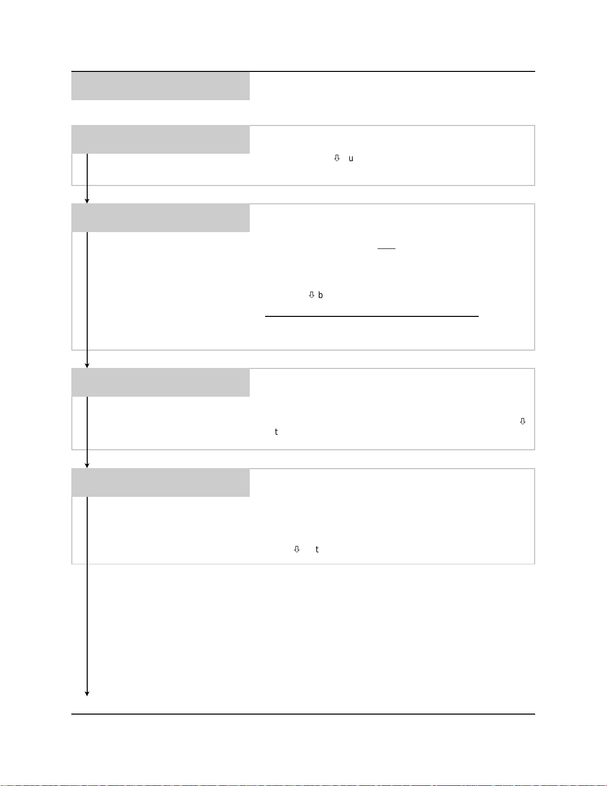
UNIT OF MEASURE = US
1=US 2=METRIC 3=IMPERIAL
FLUSH TIME 10 SEC
TO DRAIN AFTER 02 SEC
SIMULTANEOUS PUMPS = OFF
1=OFF 2=ON
This menu selection allows you to change the unit of measure.
Use the number buttons to choose the desired unit of measure.
Press the MENUbutton to move on to the next menu selection.
Disregard this menu for systems without flush manifold.
This menu selection allows you to set flush time (how long the
flush solenoid is activated after
drain after” time (the time delay before the optional 3-way valve is
activated). These settings let you custom tailor the system to
meet your particular flush and drain requirements. Use the
number buttons to set the times and, then press ENTER. Press
the MENUbutton to move on to the next menu selection.
Factory defaults and minimum settings are as follows:
Flush:
Default is 10 seconds / minimum is 2 seconds.
To Drain After:
This menu selection allows you to choose if you want all pumps to
operate simultaneously. W hen this selection is on, all pumps will
run at the same time. W hen this selection is off, pumps will run in
sequence from left to right (lowest number to highest). Use the
number buttons to make your selection. Press the MENU
button to move on to the next menu selection.
Default is 2 seconds / minimum is 2 seconds.
the c hemical injection) and “to
FLUSH ERROR SAMPLING
DELAY = 00 SECONDS
SETUP ROUTINES MENU HEADING
Page 10 of 20 0900511 Rev: D (04/03)
Disregard this menu for systems without flush manifold.
This menu selection allows you to set the amount of time that the
optional flow sensor switch can “break” contact before giving a
flush error. Use the number buttons to set the sampling time and,
then press ENTER. Leave the setting at 00 if a flow switch is not
used (typical for most flush manifold applications). Press the
MENUbutton to move on to the next menu.
Page 11
*** DISPENSER ***
3
REPORT SETUP ROUTINES
• Change user access code
• Change user password
• Change formula access
• Change report name
• Change chemical names
• Change product costs
• Change formula names
• Set shift times
• Set operating zone
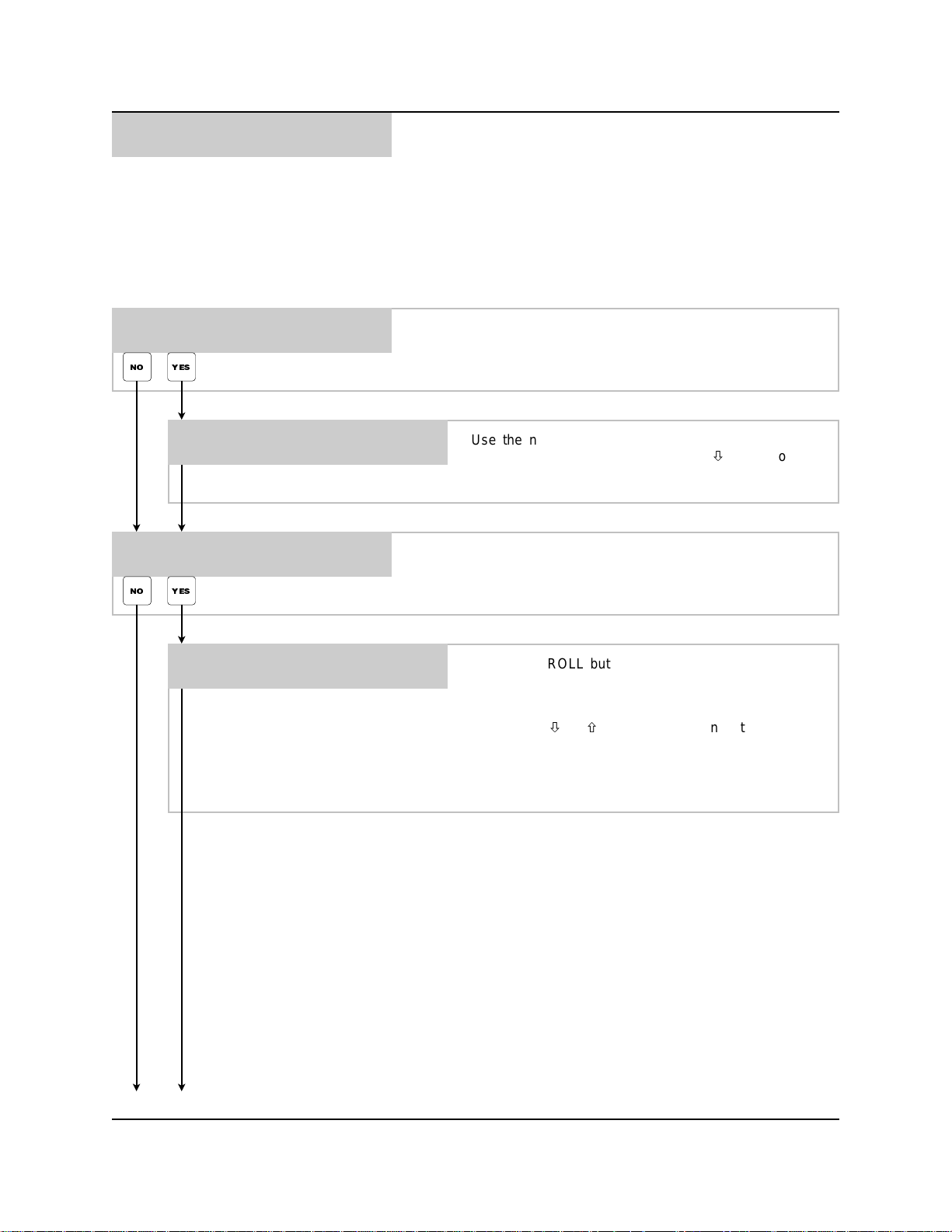
CHANGE USER ACCESS CODE ?
PRESS: YES OR NO
NO YES
USER ACCESS CODE = 000
THEN PRESS ENTER
CHANGE USER PASSWORD ?
PRESS: YES OR NO
NO YES
001 000 USER ID NAME 01
CHANGE VALUES THEN ENTER
This menu selection allows you to change the user access code.
Press YES to invoke the command, or press NO to move on to
the next menu selection.
Use the number buttons to set the user access code,
then press ENTER. Press the MENUbutton to move
on to the next menu selection.
This menu selection allows you to change user passwords. Press
YES to invoke the command, or press NO to move on to the next
menu selection.
Use the SCROLL buttons and alphanumeric keypad to
enter a 3-digit password and descriptive name (up to 15
characters) for the user ID number shown (3-digit
number on the left side of display) then press ENTER.
Use MENUorto review or change the password
and descriptive name of other user ID numbers. Press
RESET when finished and you will be returned to the
previous screen.
GO TO NEXT PAGE
0900511 Rev: D (04/03) Page 11 of 20
Page 12
*** DISPENSER ***
3
REPORT SETUP ROUTINES
• Continued
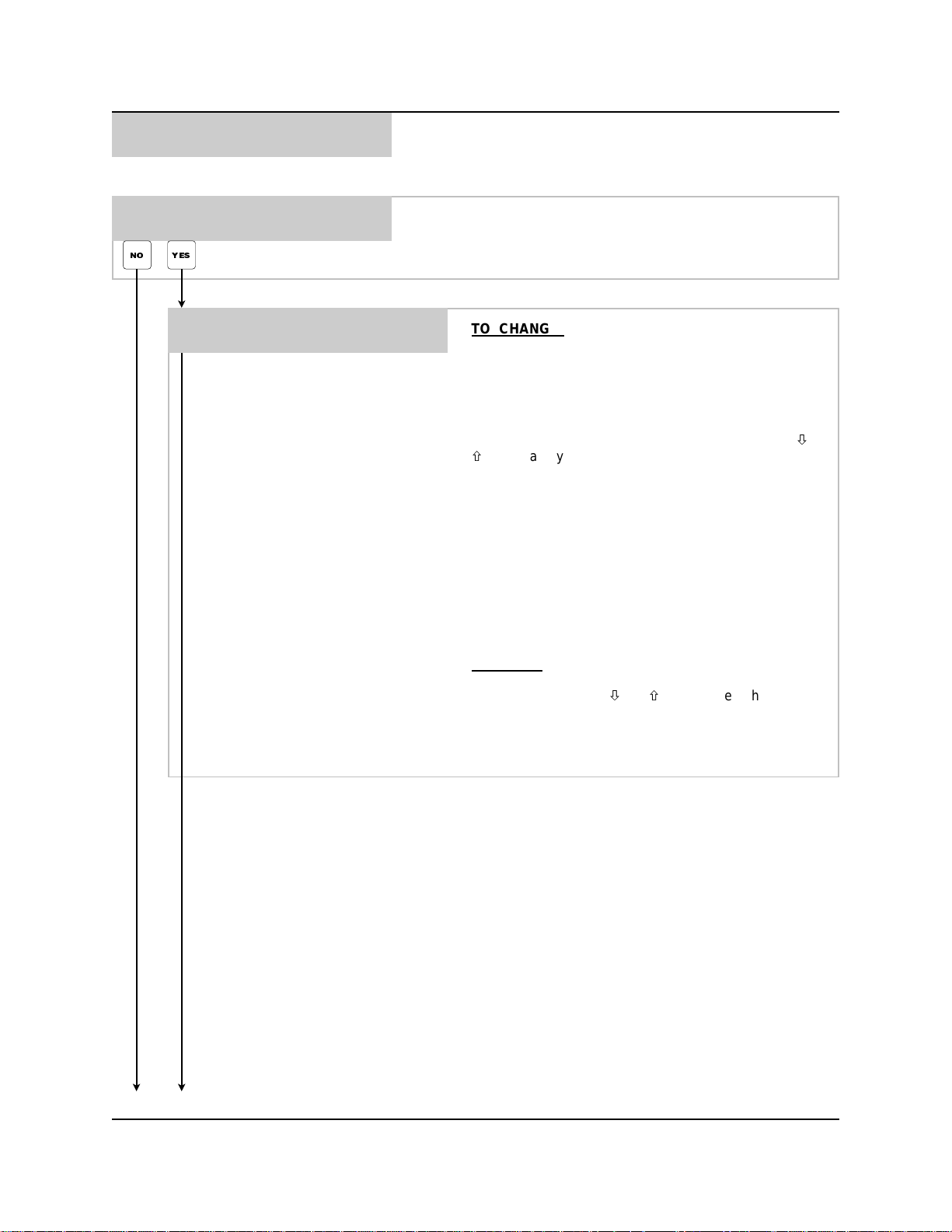
CHANGE FORMULA ACCESS ?
PRESS: YES OR NO
NO YES
001 FORM-01020304
USER ID NAME 1 1 1 1
This menu selection allows you to restrict the users access to
specific formulas. Press YES to invoke the command, or press
NO to move on to the next menu selection.
TO CHANGE: Type in the user ID number and press
ENTER. Then use the SCROLL buttons to move to the
cursor below the formula you wish to change. Choose 1
(enabled) or 0 (disabled) for each formula shown (note:
the PRIME/CAL button will change all formulas shown to
0) and press ENTER. W hen ENTER is pressed, you are
only changing the formula number “set” that is shown on
the display. To change other formulas, use MENUor
then make your changes to the formula set shown and
press ENTER again. The following paragraphs explain
the information shown on the window.
Top line:
(001 - 400). The next set of double digits represent the
formula numbers.
Bottom line:
user’s descriptive name. The numbers below the formula
numbers show which formulas this user can access. 1
means the formula is allowed, 0 means the formula is
not allowed.
The first three digits are the user ID number
The first thirteen characters indicate the
GO TO NEXT PAGE
TO VIEW:
ENTER. The screen will display current settings for each
formula. Use MENUorto choose other formula
numbers.
Press RESET when finished and you will be returned to
the previous screen.
Type in the user ID number and press
Page 12 of 20 0900511 Rev: D (04/03)
Page 13
*** DISPENSER ***
3
REPORT SETUP ROUTINES
• Continued
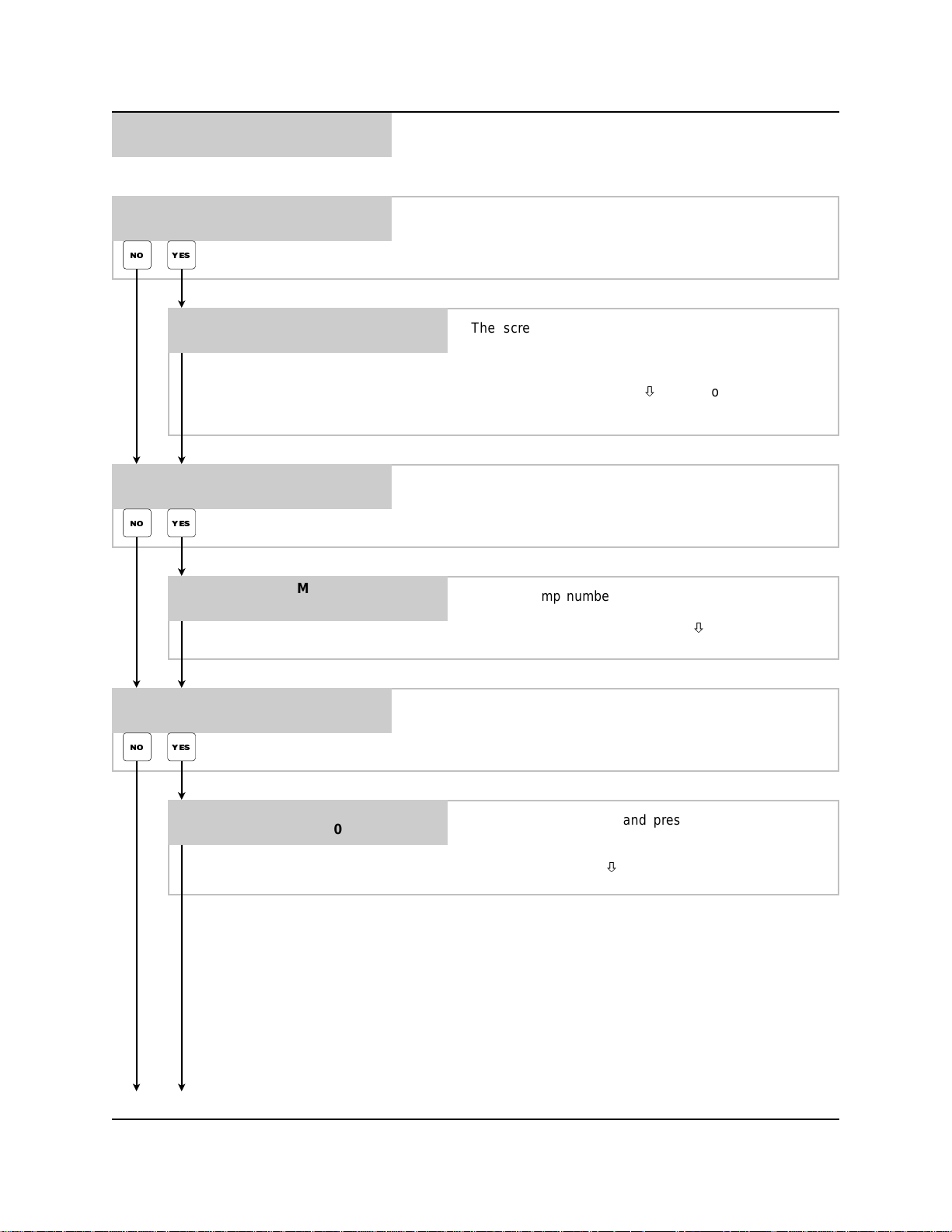
CHANGE REPORT NAME ?
PRESS: YES OR NO
NO YES
CHANGE CHEMICAL NAMES
PRESS: YES OR NO
NO YES
PUMP 01
PUMP-01
This menu selection allows you to change the report name. Press
YES to invoke the command, or press NO to move on to the next
menu selection.
The screen will be blank with only a blinking cursor
displayed. Use the alphanumeric buttons to set the
report name (up to 23 characters on each line) and the
SCROLL buttons to move the cursor position, then press
ENTER. Press the MENUbuttontomoveontothe
next menu selection.
This menu selection allows you to change the chemical names.
Press YES to invoke the command, or press NO to move on to
the next menu selection.
Choose pump number and press ENTER. Move cursor
(SCROLL) to set the product name and press ENTER.
Repeat for all pumps. Press MENUwhen finished.
CHANGE PRODUCT COSTS ?
PRESS: YES OR NO
NO YES
PUMP 01 $00.00 /GALS
GO TO NEXT PAGE
This menu selection allows you to change the product costs.
Press YES to invoke the command, or press NO to move on to
the next menu selection.
Choose pump number and press ENTER. The screen
will display the current value. Move cursor (SCROLL) to
enter the product cost and press ENTER. Repeat for all
pumps. Press MENUwhen finished.
0900511 Rev: D (04/03) Page 13 of 20
Page 14
*** DISPENSER ***
3
REPORT SETUP ROUTINES
• Continued
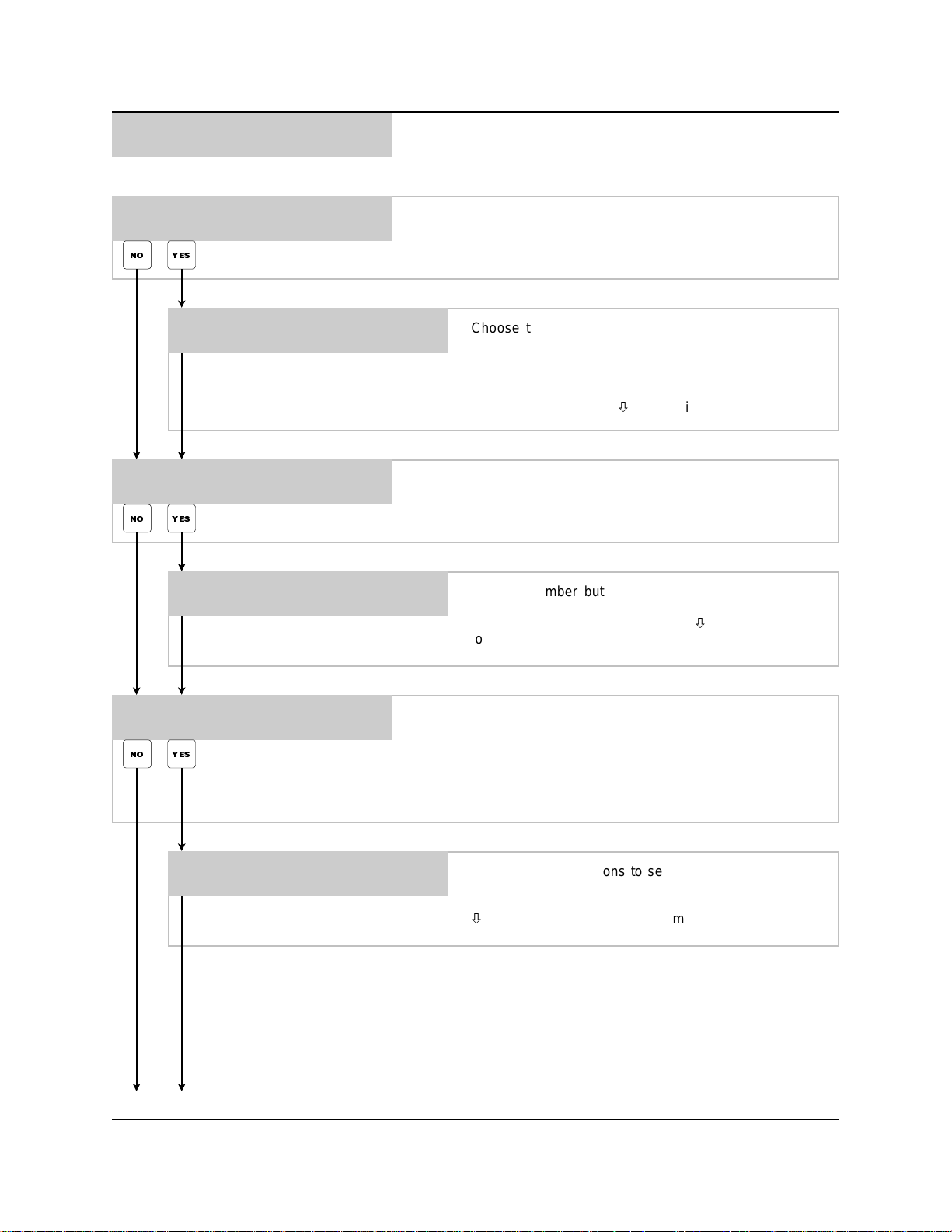
CHANGE FORMULA NAMES ?
PRESS: YES OR NO
NO YES
FORMULA 01
FORMULA 01
WANT TO SET SHIFT TIMES ?
PRESS: YES OR NO
NO YES
START TIMES #1 06:00
#2 11:00 #3 17:00
This menu selection allows you to change formula names. Press
YES to invoke the command, or press NO to move on to the next
menu selection.
Choose the formula number on the top line and press
ENTER. The current formula name will appear on the
bottom line. Move the cursor to the bottom line
(SCROLL) and use alphanumeric buttons to enter the
formula name, then press ENTER. Repeat for all
formulas. Press MENUwhen finished.
This menu selection allows you to enter shift times. Press YES to
invoke the command, or press NO to move on to the next menu
selection.
Use the number buttons to enter the shift start times,
then press ENTER. Time m ust be in military format (i.e.
13:00 = 1:00 PM) Press the MENUbuttontomoveon
to the next menu selection.
SET OPERATING ZONE ?
PRESS: YES OR NO
NO YES
START TIME 00:00
END TIME 24:00
REPORT SETUP ROUTINES MENU HEADING
This menu selection allows you to set the operating zone. The
operating zone is the time range in which formulas can be access
to dispense. Formulas cannot be access to dispense during any
time outside the operating zone. Press YES to invoke the
command, or press NO to move on to the next menu selection.
Use the number buttons to set the start and end times
of the operating zone, then press ENTER. Time m ust be
in military format (i.e. 13:00 = 1:00 PM) Press the MENU
button to move on to the next menu.
Page 14 of 20 0900511 Rev: D (04/03)
Page 15
*** DISPENSER ***
4
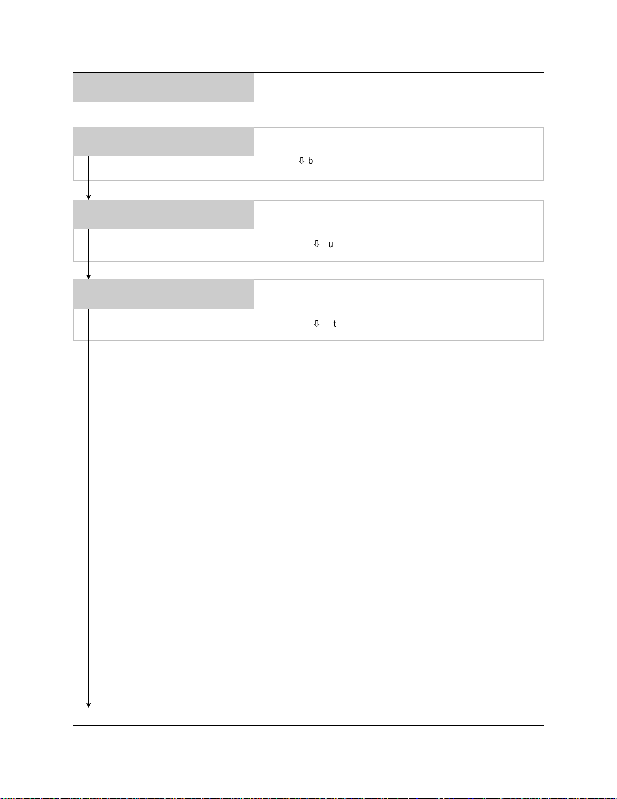
MAINTENANCE SCHEDULE
• Date dispenser installed
• Date squeeze tube last changed
• Date squeeze tube last lubed
DISPENSER INSTALLED
00/00/00
SQUEEZE TUBES CHANGED
PUMP 01 00/00/00
SQUEEZE TUBES LAST LUBED
PUMP 01 00/00/00
This menu selection allows you to set the installation date. Use
the number buttons to set the date, then press ENTER. Press the
MENUbutton to move on to the next menu selection.
This menu selection allows you to set the date that the squeeze
tubes were last changed. Use the number buttons to set the date,
then press ENTER. Do this for each pump in the system Press
the MENUbutton to move on to the next menu selection.
This menu selection allows you to set the date that the squeeze
tubes were last lubed. Use the number buttons to set the date,
then press ENTER. Do this for each pump in the system Press
the MENUbutton to move on to the next menu selection.
MAINTENANCE SCHEDULE MENU HEADING
0900511 Rev: D (04/03) Page 15 of 20
Page 16
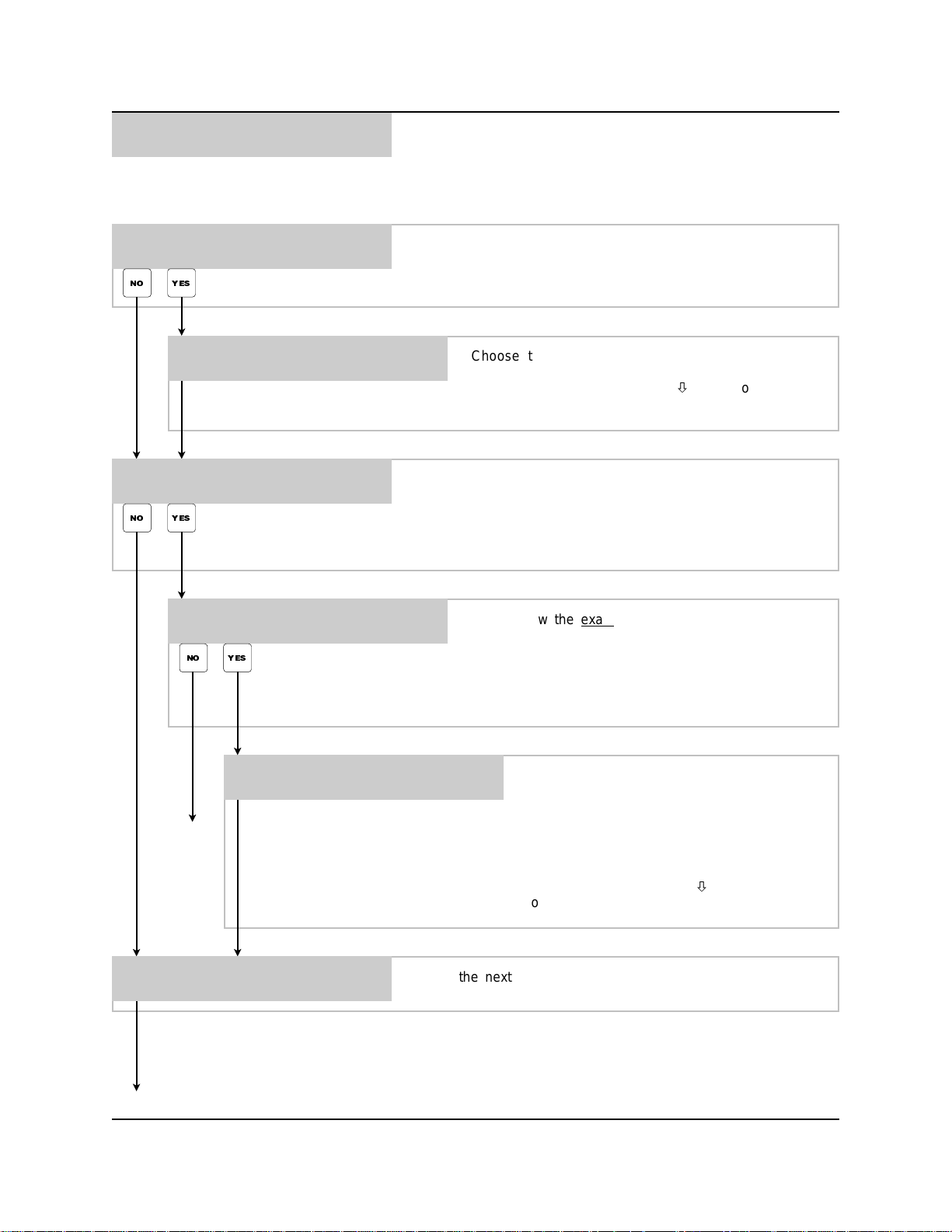
*** DISPENSER ***
5
PROGRAMMING ROUTINES
• Prime pumps
• Calibrate pumps
• Manually enter pump flow rates
• Program formulas
PRIME PUMPS ?
PRESS: YES OR NO
NO YES
PRIMEPUMP01
PUSH PRIME TO START/STOP
CALIBRATE PUMPS ?
PRESS: YES OR NO
NO YES
MANUALLY ENTER FLOW RATE
PRESS: YES OR NO
YES NO
This menu selection allows you to prime each chemical pump.
Press YES to invoke the command, or press NO to move on to
the next menu selection.
Choose the pump number you wish to prime. Press
PRIME to start and stop the pump. Repeat for as each
pump desired. Press the MENUbuttontomoveonto
the next menu selection.
This menu selection allows you to calibrate the chemical pumps.
Press YES to invoke the command, or press NO to move on to
the next menu selection.
NOTE: Pumps must have a flow rate for formulas to be valid.
If you know the exact flow rate of the pump, you can
choose to manually enter the value instead of
calibrating, however it is recommended to calibrate each
pump as flow rates can vary due to chemical viscosity.
Press YES to invoke the command, or press NO to move
on to the next menu selection.
FLOW RATES PER MINUTE
P-01 000.0 OZ
Choose the pump number and press ENTER
while the blinking cursor is on the pump
number. Move the cursor to the right using
GO TO
NEXT
PAGE
SCROLL, then set the flow rate and unit of
measu r e (PRIME/CAL button alternates
between gallons / ounces, or liters / milliliters)
and press ENTER. Repeat for all pumps
required. Press the MENUbutton to move on
to the next menu selection.
FORMULA 01 PUMP 01
VOL 000.0 OZS
GO TO NEXT PAGE
Page 16 of 20 0900511 Rev: D (04/03)
Go to the next page (after calibration steps) for details on this
menu selection
Page 17
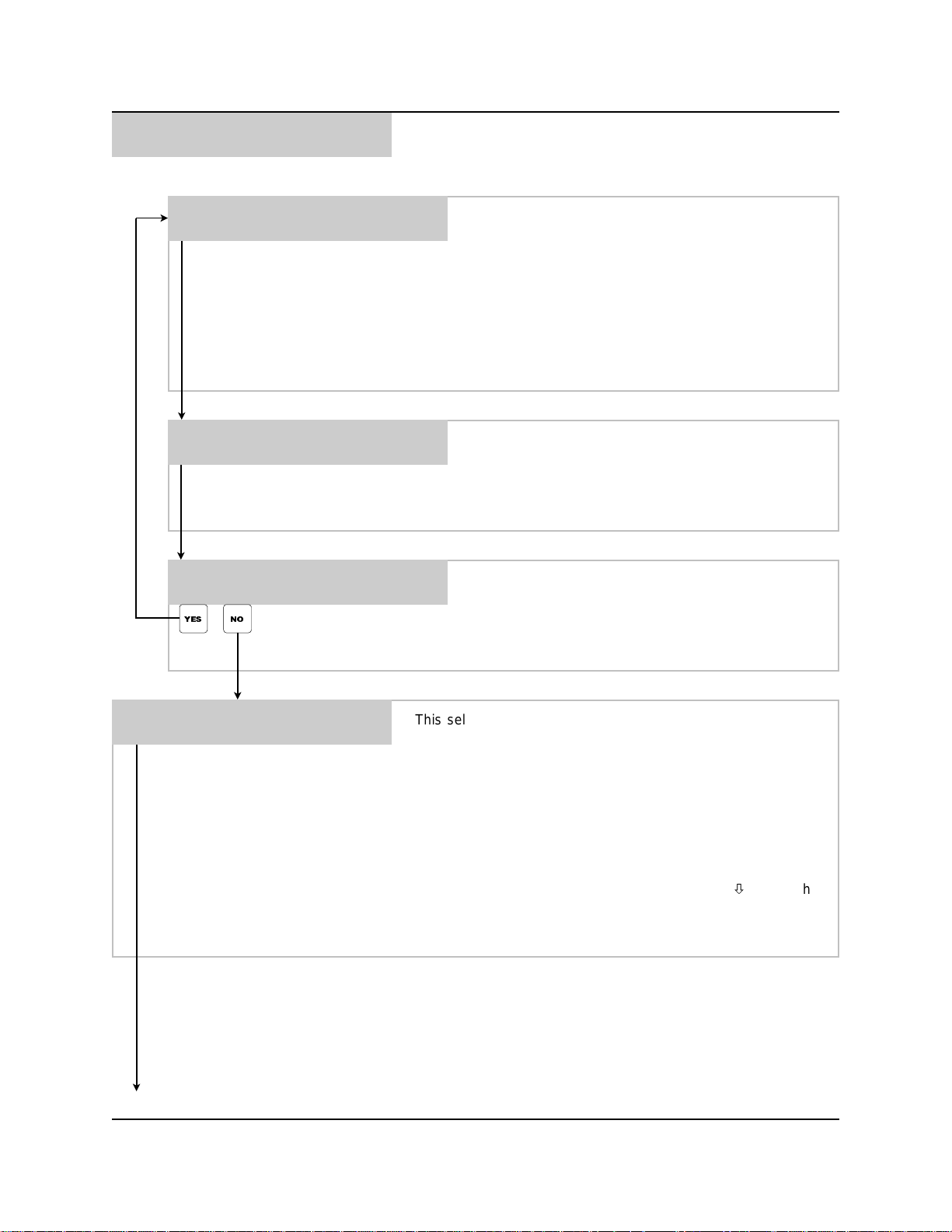
*** DISPENSER ***
5
PROGRAMMING ROUTINES
• Continued
CALIBRATE PUMP 01
PRESS CAL. TO START/STOP
ENTER CALIBRATION
VOL PUMPED = 000.0 OZS
CALIBRATE ANOTHER ? Y/N
P-01 000.0 OZ
NO YES
Use a container with calibration marks for this process,
such as a beaker or graduated cylinder (minimum 1/2
gallon recommended — larger containers will yield more
accurate calibrations). Also make sure that the pump
suction lines are fully primed.
Enter the pump number to be calibrated, then place your
container under the discharge tube of the pump. Press
the CAL button and the pump will start. Let the pump run
for about 60 seconds, then press CAL again to stop. You
will advance to the next s tep automatically.
Enter the actual volume pumped into your container,
then press ENTER. Units will be in ounces or milliliters
(only) depending on which “unit of measure” you chose
in menu #2. The system will then determine the flow rate
and will automatically advance to the next step.
Press YES to repeat the calibration process for another
pump. Be sure to calibrate all pumps in the system
(including pump #9 if using water in the formula
programming). If all pumps have been calibrated press
NO to continue on to the next step.
FORMULA 01 PUMP 01
VOL 000.0 OZS
PROGRAMMING ROUTINES MENU HEADING
This selection is used to input up to 99 formulas. A formula can
consist of one or more chemicals with different volumes of
chemical per formula. Each formula can include water (pump #9)
for dilution if desired. If pump #9 is programmed on a formula, it
must also have be calibrated and have a flow rate.
Choose the formula and pump number and press ENTER while
the blinking cursor is on the top line. Then move the cursor to the
bottom line (using SCROLL), set the desired volume (the PRIME/
CAL button alternates between gallons and ounces, or liters and
milliliters) and press ENTER. Repeat the process for all desired
pump and formula combinations. Press the MENUbutton when
finished.
NOTE: minimum on-time is 2 seconds.
0900511 Rev: D (04/03) Page 17 of 20
Page 18
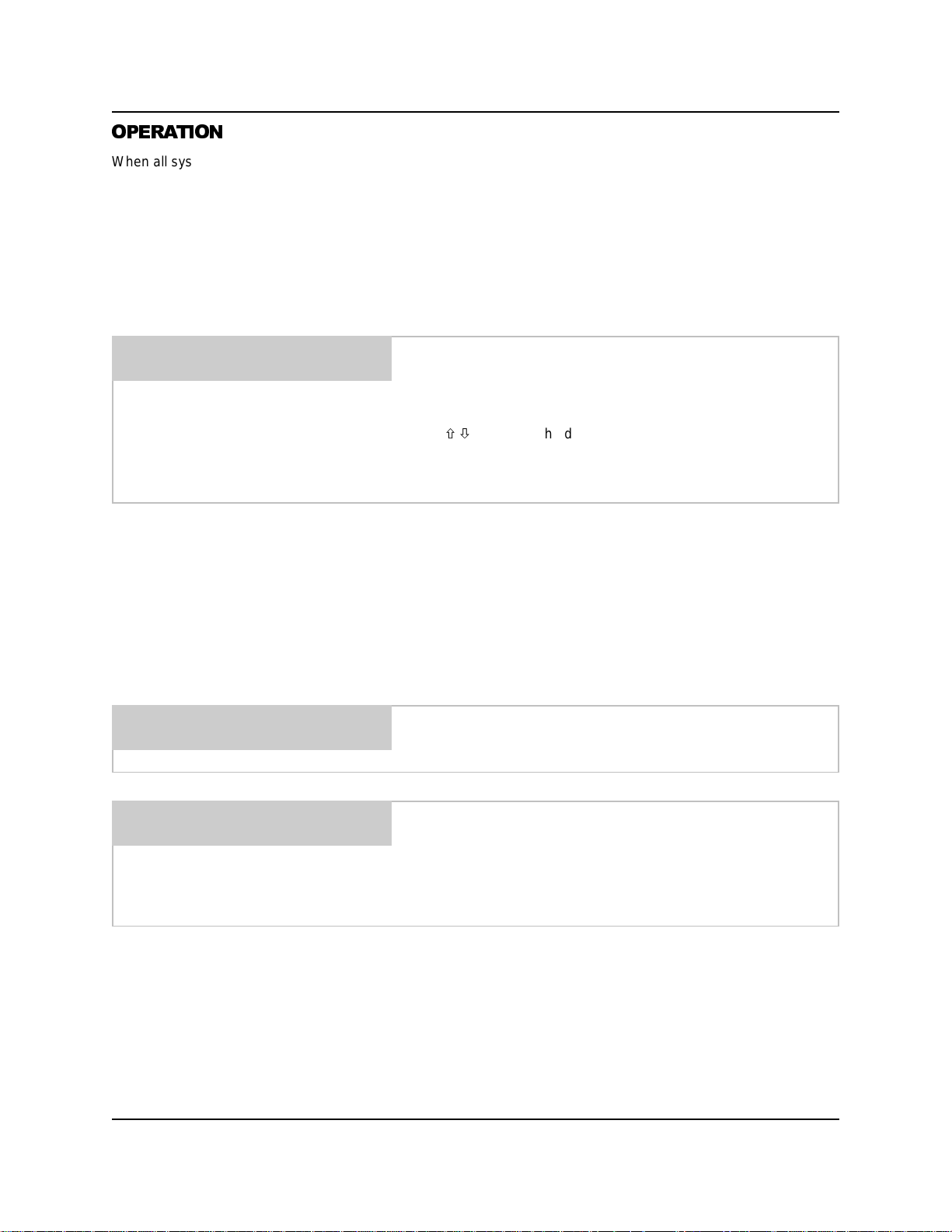
OPERATION
When all system programming is complete, you will be ready for operation. Check that all chemical lines are primed
and that the water source is turned on if using a flush manifold.
(1) Press Main Power switch to ON position.
(2) Insert the key and turn to the right (key cannot be removed when on).
(3) Place container under the discharge spout.
(4) Type in your user password and press ENTER — if your password was accepted, the display will flash a brief
acknowledgement and you will then see the following.
FORMULA 01
SELECT FORMULA/HIT START
– The top line will show the current formula name.
– The bottom line will alternate between the date/time and the
display shown to the left.
Use/to choose the desired formula, then press START.Ifthe
message “ACCESS RESTRICTED” appears, it indicates that the
current user is not allowed to dispense the formula selected.
Otherwise, the unit will operate as follows.
• Chemicals will begin pumping, starting with the lowest number pump to the highest number (if there is more than
one chemical programmed in the formula).
• If simultaneous pumps option is turned ON, then all pumps on the formula will run together (if there is more than
one chemical programmed in the formula).
• The display will count down the remaining time left to pump.
• When pumps are finished, the flush will activate for its programmed time, and the 3-way valve (if used) will
activate after the time set to drain after.
• If the RESET button is pressed during operation, you will then see the following message.
ABORT CURRENT BATCH?
PRESS: YES OR NO
– If you press NO, the system will finish the batch as normal.
– If you press YES, you will then see the following.
FLUSH SYSTEM?
PRESS: YES OR NO
Page 18 of 20 0900511 Rev: D (04/03)
Choose if you want to flush the system from any remaining
chemical. The pumps will not run during this function.
When finished, the system will return to the default display and
will record the
programmed
actual
amount) in the batch tracking memory.
amount dispensed (instead of the
Page 19

NOTES
0900511 Rev: D (04/03) Page 19 of 20
Page 20
DISCLAIMER
Knight Inc. does not accept responsibility for the mishandling, misuse, or non-performance of the described items
when used for purposes other than those specified in the instructions. For hazardous materials information consult
label, MSDS, or Knight Inc. Knight products are not for use in potentially explosive environments. Any use of our
equipment in such an environment is at the risk of the user, Knight does not accept any liability in such
circumstances.
WARRANTY
All Knight controls and pump systems are warranted against defects in material and workmanship for a period of
ONE year. All electronic c ontrol boards have a TWO year warranty. Warranty applies only to the replacement or
repair of such parts when returned to factory with a Knight Return Authorization (KRA) number, freight prepaid, and
found to be defective upon factory authorized inspection. Bearings and pump seals or rubber and synthetic rubber
parts such as “O” rings, diaphragms, squeeze tubing, and gaskets are considered expendable and are not covered
under warranty. Warranty does not cover liability resulting from performance of this equipment nor the labor to
replace this equipment. Product abuse or m isuse voids warranty.
KNIGHT INC.
World Headquarters: 20531 Crescent Bay Drive, Lake Forest, CA 92630-8825 (USA) TEL: 949-595-4800, FAX: 949-595-4801, www.knightequip.com
Atlanta Branch:
415 Gees Mill Business
Court NE, Suite 200
Conyers, GA 30013 USA
TEL: 770-760-8777
FAX: 770-761-0199
Toronto Branch:
2880 Argentia Road, Unit 6
Mississauga, Ontario
L5N 7X8 Canada
TEL: 905-542-2333
FAX: 905-542-1536
London Branch:
#15 Brunel Centre
Newton Road, Crawley
West Sussex UK RH10 9TU
TEL: 44-1293-615570
FAX: 44-1293-615585
A Unit of IDEX Corporation
Sydney Branch:
Unit 28, 317-321
Woodpark Rd., Smithfield
NSW Australia 2164
TEL: 61-29-725-2588
FAX: 61-29-725-2025
AmsterdamBranch:
Marssteden 68
7547 TD Enschede
The Netherlands
TEL: 31-53-428-58-00
FAX: 31-53-428-58-09
Spain Branch:
Port Ginesta, Local 210
08860 Sitges
Barcelona Spain
TEL: 34-936-342-130
FAX: 34-936-643-477
Page 20 of 20 0900511 Rev: D (04/03)
 Loading...