

Knight Equipment LT-300 Installation Manual

LT-300 CIRCUIT BOARD
INSTRUCTION MANUAL
LT-300 INTRODUCTION
The LT-300 is a timing module capable of enabling a pump motor to run when an electrical signal is received. The
pump run time can be set from 0.5 seconds to 12 minutes and is easily adjusted. Pump voltages can range from 24
to 240 volts AC or DC. Many different pump sizes and configurations are available. Consult your nearest Knight
representative for details.
LT-300 OPERATION
(1) For AC output devices, the LT-300 accepts input power ranging from 24 to 240 VAC and "switches" this voltage
to output terminals marked COM and OUT (AC OUT). For example; a 115 VAC motor can be connected to the
COM and OUT terminals if 115 VAC is applied to the 24-240VAC power input terminals.
(2) For DC output devices, such as a 24 VDC motor, the positive side of the motor is connected to the DC OUT (+)
terminal, and the negative side is connected to the DC OUT (-) terminal. 24 VAC should be applied to the 24-240
VAC power input terminals (the circuit board will convert AC to DC).
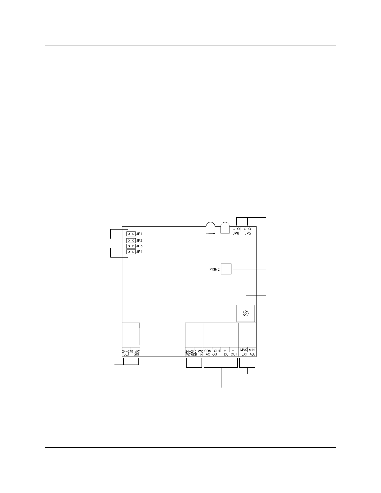
(3) The minimum and maximum run time range of the pump (or other output device) is determined by selecting a
jumper on the left side of the LT-300. The potentiometer (also called a "pot") on the board adjusts the actual time
within the selected range. Choose a range that's closest to your desired run time -- this will make setting the time
easier and more accurate. Jumper settings for time ranges are as follows:
JP1 selects time range from .5 sec. to 10 sec.
JP2 selects time range from 2 sec. to 45 sec.
JP3 selects time range from 5 sec to 3 min.
JP4 selects time range from 15 sec to 12 min.
(4) Activation of the LT-300 is possible through any one of three methods.
●
Terminals marked DET and SIG (24-240VAC) accept a signal voltage from 24-240 volts (AC or DC) and, when
received, activate the pump or output device for the set time set.
●
The signal terminals can be connected to the main power input wires, allowing the output device to “autostart”
when main power is received. (NOTE: Only one pair of signal wires can be connected to the LT-300 signal input
terminals).
●
An external start switch can be used to enable the LT-300 (see wiring diagram for details).
(5) The output voltage of the LT-300 can be selected to be “on” or “off” during the activation time. This feature is set
via the N/O and N/C jumpers labeled JP5 and JP6. For a pump or other device to be “on” during the activation
time, set the LT-300 for N/O (normally open, or “off“) operation by installing jumper JP6. To set the LT-300 to be
“off“, set the LT-300 for N/C (normally closed, or “on“) operation by installing JP5.
CAUTION: Wear protective clothing and eyewear when dispensing chemicals or other materials.
Observe safety handling instructions (MSDS) of chemical manufacturers.
CAUTION: To avoid severe or fatal shock, always disconnect main power when servicing the unit.
0901068 Rev: A (08/03) Page 1 of 4
LT-300 INSTALLATION
(1) Ensure that the main power input to the LT-300 is between 24-240 volts (AC or DC). Ensure that the pump
voltage (or other output device) matches the main power input. Connect main power to the 24-240 VAC
(POWER IN) terminals, and connect the pump to the COM and OUT (AC) or + and - (DC) terminals.
(2) If a signal will be used, connect 24-240 volt (AC or DC) signal wires to the terminals marked DET and SIG. If
“autostart” is desired, connect these terminals to the 24-240VAC (POWER IN) terminals.
(3) Select the N/O or N/C operation mode as described previously in OPERATION, step #5.
(4) Select the time range and time as described previously in OPERATION, step #3.
(5) Press the prime switch on the LT-300 to prime the pump — the pump will run for the set time and then shut off.
Note that the LED Illuminates when the device is on. If the run time needs to be changed, make adjustments to
the pot (clockwise to increase, counter-clockwise to decrease) and prime again to check. You may need to use a
different time range (set with jumpers) if the desired time can’t be achieved with the range selected presently.
(6) If an external start switch will be used, connect according to the wiring diagram in this manual.
N/O AND N/C JUMPERS
TIME SELECT JUMPER S
SIGNAL INPUT TERMINALS
POWER INPUT TERMINALS
OUTPUT TERMINALS
PRIME SWITCH
TIME ADJUST P OT
EXTERNAL POT CONNECTION
(CUSTOM VERSIONS ONLY)
Page 2 of 4 0901068 Rev: A (08/03)
 Loading...