

Knight Equipment KLE 175GT Installation Manual
'LVKPDFKLQH
./(*7
Three Door Configuration
INSTRUCTION MANUAL
and
PART S MANUAL
CONTENTS
INSTRUCTION MANUAL
INTRODUCTION Page 1
INSTALLATION Page 1
INITIAL OPERATION Page 2
TIME SETTINGS Page 3
JUMPER SETTINGS Page 4
CIRCUIT BOARD BUTTONS Page 4
NORMAL OPERATION Page 4
DOOR CONVERSION Page 5
SCRAP TRAP CONVERSION Page 7
MAINTENANCE SCHEDULE Page 8
TROUBLESHOOTING Page 9
ELECTRICAL DIAGRAM Page 10
WARRANTY Page 11
PARTS MANUAL
ELECTRICAL BOX Page 13
PLUMBING Page 14
WRAPPER Page 15
PAN Page 16
PUMP Page 17
STAND Page 18
ACCESSORY KIT Page 19
Page 12
Headquarters: 20531 Crescent Bay Drive, Lake Forest, CA 92630 U.S.A. (949) 595-4800
Atlanta Branch: 8111 Technology Dr. NE Covington, GA 30014 USA TEL: 770-787-9400
Toronto Branch: 2880 Argentia Road, Unit 6 Mississauga, Ontario L5N 7X8 Canada TEL: 905-542-2333
London Branch: #15 Brunel Centre Newton Road, Crawley West Sussex UK RH10 9TU TEL: 44-1293-615570
Sydney Branch: Unit 28, 317-321 Woodpark Rd., Smithfield NSW Australia 2164 TEL: 61-29-725-2588
Amsterdam Branch: Marssteden 68 7547 TD Enschede The Netherlands TEL: 31-53-428-58-00
Spain Branch: Port Ginesta, Local 210 08860 Sitges Barcelona Spain TEL: 34-936-342-130
(11/10/01) Revision F, EO 4109 Part No. 9641606
INTRODUCTION
The KLE 175 GT dishwasher is designed to provide years of excellent warewash results under many types of
conditions. Each unit is configured as an automatic start dishwasher, meaning that the dishwasher starts when
the doors are closed. The dishwasher includes a three product chemical dispenser located on top of the dishwasher which dispenses liquid detergent, rinse product, and a chemical sanitizer suitable for low temperature
(recommended 140 deg. F applications.) Options and additional features are also available. Contact your nearest Knight representative for more details.
INSTALLATION - Caution –
Access into electrical enclosure must be performed by authorized personnel.
1. Inspect the dishwasher upon initial receipt. Lift the door arm and open the accessory package located inside
the dishwasher. Note that it includes spray arms and other equipment required for installation.
2. Examine the spot where the dishwasher is to be operated. Insure that all electrical and plumbing connections,
as well as dish table placement have been considered for installation. Parameters:
Electrical Water line Drain line
- 120V 20 AMP circuit or
- 240V 10 AMP circuit (not field
20 psi flow pressure 140 deg. F
3/4” FPT on machine
1-1/2” MPT on scrap accumulator
convertible)
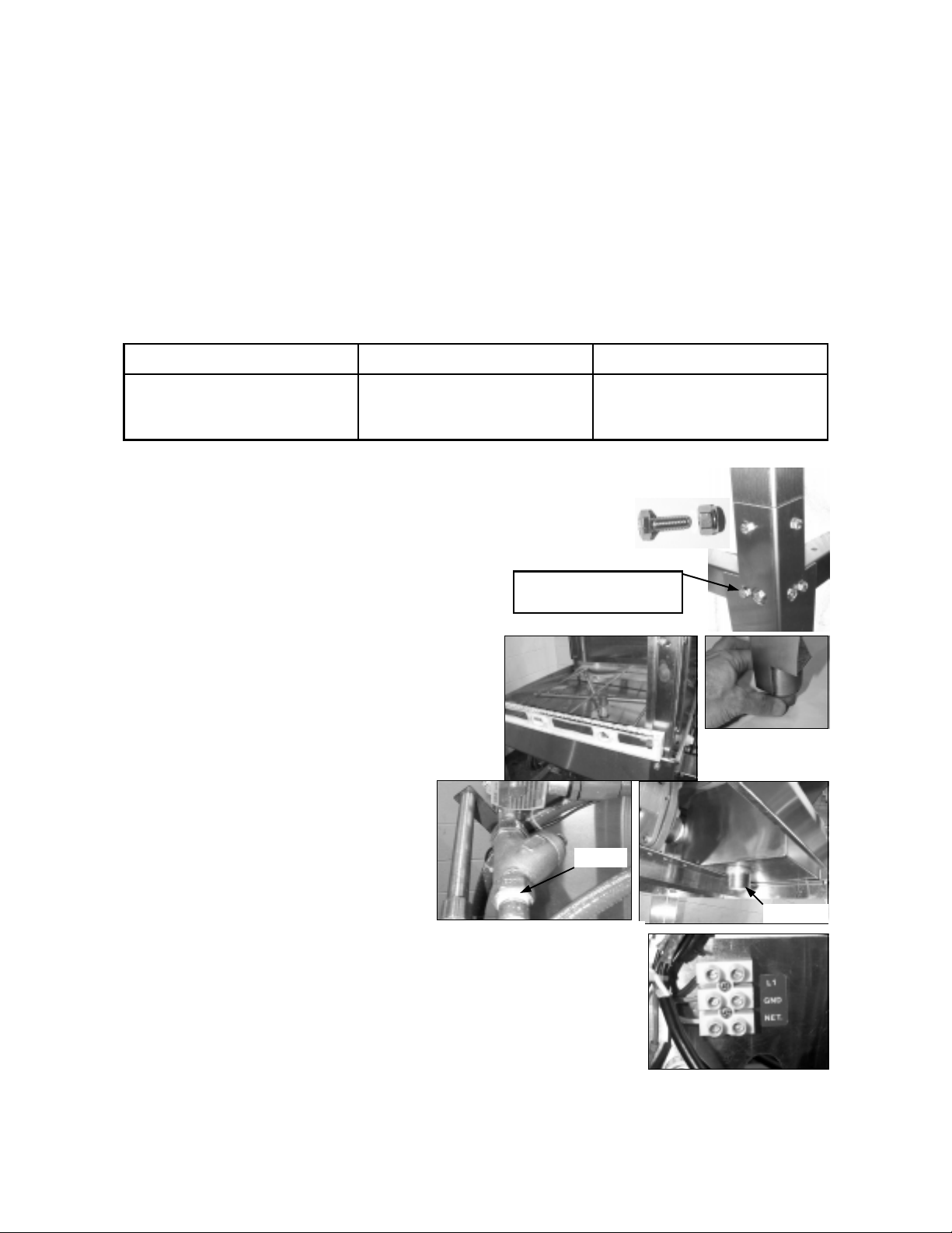
3. Install leg extensions. Each leg requires 4 bolt assemblies, 1/4-20x1/2” long, to secure legs to dish machine. Bolts are located in the accessory kit envelope and on
stand. This job requires two people. Lean the machine back and install two leg
extensions, lean the machine in the other direction and install the other two legs.
4. Install detergent, sanitizer, and rinse tubing to the peristaltic pumps. Use the provided hose clamp ties to secure
delivery tubing to squeeze tubing. Feed outlet tubing to 70
Attached to stand, remove and
reinstall to attach legs
deg. elbow on side of pan directly over the sump. Tubing
installation is easier if done before tabling installation.
5. Place the dishwasher at the spot desired for
normal operation. Level the dishwasher using
adjustable bullet feet at the bottom of the legs.
Install spray arms included in the accessory box.
6. Connect hot water supply line to the 3/4 FPT
line strainer at rear of machine. Ensure that water pressure is sufficient for fill (approx. 10
3/4 FPT
GPM flow @ 20 psi.). Connect drain to 1-1/2”
MPT nipple on scrap accumulator.
7. Make electrical connections (refer to data plate for voltage and current ratings)
to the labeled barrier provided at the inside back of the control box. Run all electrical wire through suitable conduit and insure all connections are made in accordance with local wiring codes. It is recommended that the circuit breaker carrying
the dishwasher load have NO OTHER ELECTRICAL DEVICES connected.
1-1/2 MPT
8. Attach prewash and drying tables to the dishwasher, insuring that sufficient
space is provided for the dishwasher operator. Insure that adjustable legs on
prewash and drying tables have been adjusted for proper drainage of water.
Page No. 1
(11/10/01) Revision F, EO 4109 Part No. 9641606
INITIAL OPERATION
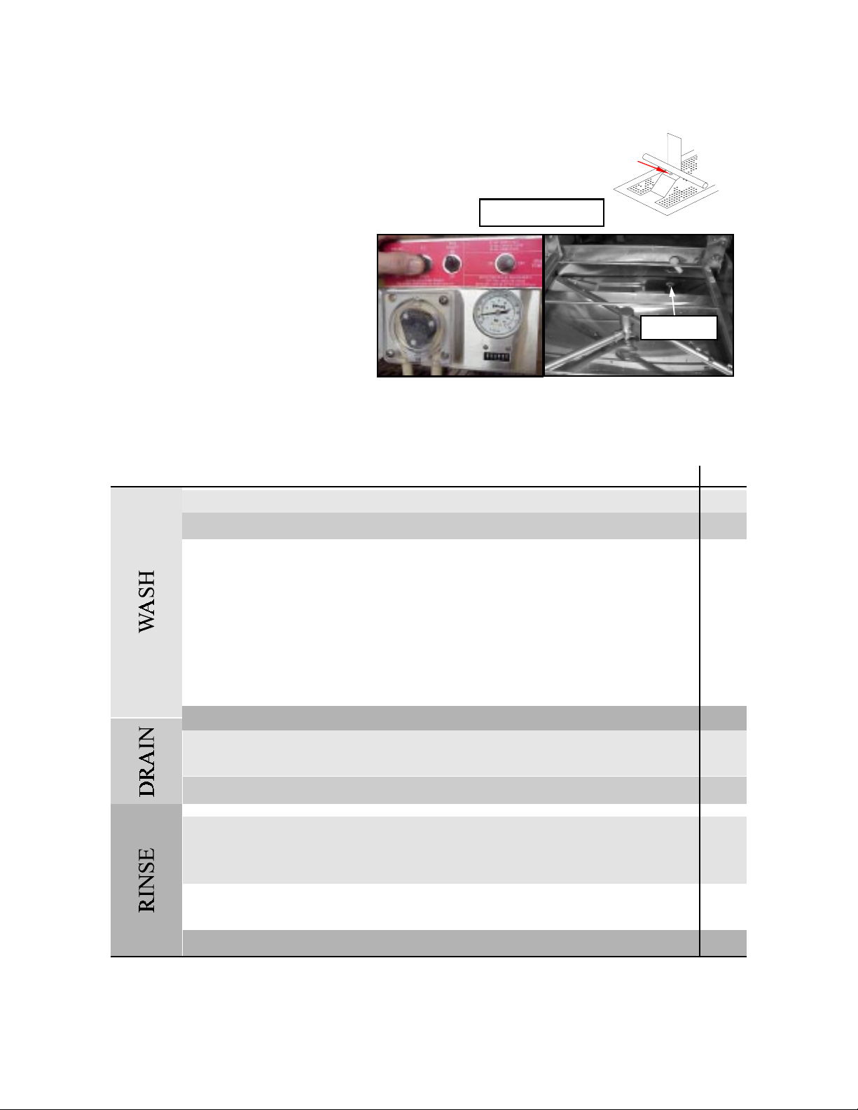
1. Check pump intake screen for proper installation.
2. Start with all switches in the OFF position
Hook tab under rod
3. Turn on main power switch. With
doors closed, flip-up the fill button to
fill the dishwasher with fresh 140 deg.
F water (120 F min.). Fill until level
with top of drain ball tube.
Water level
4. Turn ON the RUN POWER switch and with doors in closed position the machine will start to wash. Allow
machine to run through one cycle and watch machine sequence through the follo wing wash cycle: (90 second
cycle evaluated ). Machine can be adjusted to 120, 90 or 72 second cycles. See below and page 4 for more details. (Cycle adjustments will need to be done by authorized personnel only.
TIME
1 second – wash pump motor turns on
3 seconds – detergent pump runs for adjusted period of time.
0
10
20
30
40
45 seconds – drain opens and machine drains for 15 seconds.
Adjustable 48 to 60 seconds – fresh water valve opens and rinses inside of dishwasher
(drain is still open)
50
60 seconds – drain closes and fill remains open for period of time to fill dish machine.
60
70 seconds – sanitizer and rinse pumps run for an adjustable period of time.
70
70 seconds – wash pump motor stops for three seconds then starts to “burp” the
machine.
80
90 seconds – machine will stop. This is the end of the wash cycle.
90
5. Machine is factory adjusted but may need to be adjusted to local water pressure to operate properly.
Page No. 2
(11/10/01) Revision F, EO 4109 Part No. 9641606
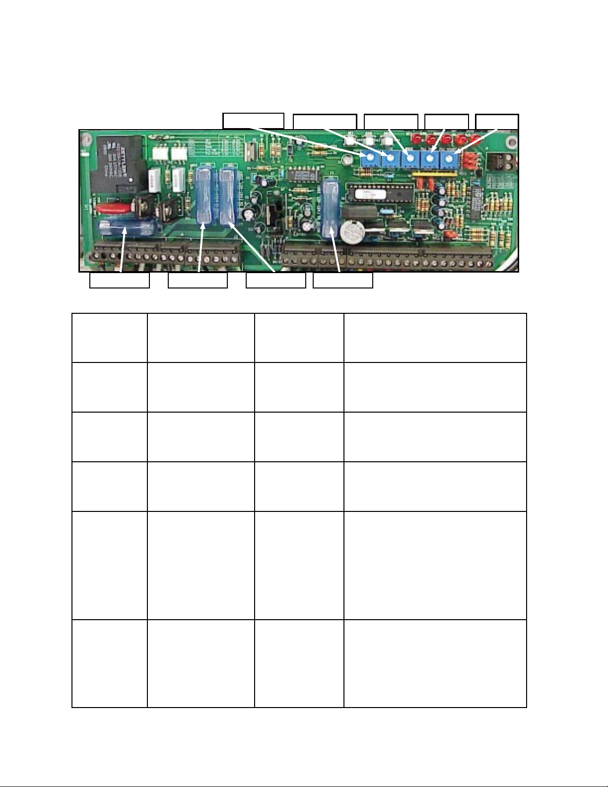
TIME SETTINGS
Time settings will need to be done by authorized personnel only. The time settings for detergent pump, fresh water fill,
sanitizer pump, and rinse pump are done inside the control box using the single turn pots. The pots control the time duration of each of the listed components. Use the chart below to make settings.
Det. Pump pot.
Fuse 1 Amp 250V Fuse 1 Amp 250V Fuse 3 Amp 250V Fuse 2 Amp 250V
POT
CONTROL
ACTIVE TIME
IN 90 SECONDS
sanitizer pump pot. rinse pump pot. Fill time pot. Fill start pot.
SPAN OF POT
TIME
ADJUSTMENT
Detergent Pump
at time = 3 seconds
2-30 seconds
COMMENTS
pot turns from 7 o'clock to 5 o'clock or 10 division. Each division is 2.7 seconds. Pump flow is
approximately 1.3 ml/sec.
Sani Pump
Rinse Pump
Fill Start
Fill Time
at time = 70 seconds
0-15 seconds
pot turns 7 o'clock to 5 o'clock or 10 divisions.
Each division is 1.5 seconds. Pump flow is approximately 1.3 ml/sec.
at time = 70 seconds
0-15 seconds
pot turns 7 o'clock to 5 o'clock or 10 divisions.
Each division is 1.5 seconds. Pump flow is approximately 1.3 ml/sec.
at time = 48 to 59
seconds
0-11 seconds
fill start is activated during the fixed drain cycle
(45 to 60 seconds) at the 7 o'clock setting time
is 0 and will start fill at 48 seconds in cycle. At
the 5 o'clock setting time is 11 seconds and will
start fill at 59 seconds in cycle. Fill start is set
according to water pressure and the required
time to rinse debris down the drain. Normal
setting at 20 psi flow pressure is 12 o'clock or
determined by fill start
10-42 seconds
5.5 seconds.
begins at the setting of the fill start. Once fill
start is set the fill time determines the duration
of time fresh water solenoid valve remains open.
7 o'clock setting time is 10 seconds, 5 o'clock
setting time is 42 seconds. Adjust according to
water pressure. Normal setting at 20 psi flow
pressure is 11 o'clock or 15 seconds.
Page No. 3
(11/10/01) Revision F, EO 4109 Part No. 9641606
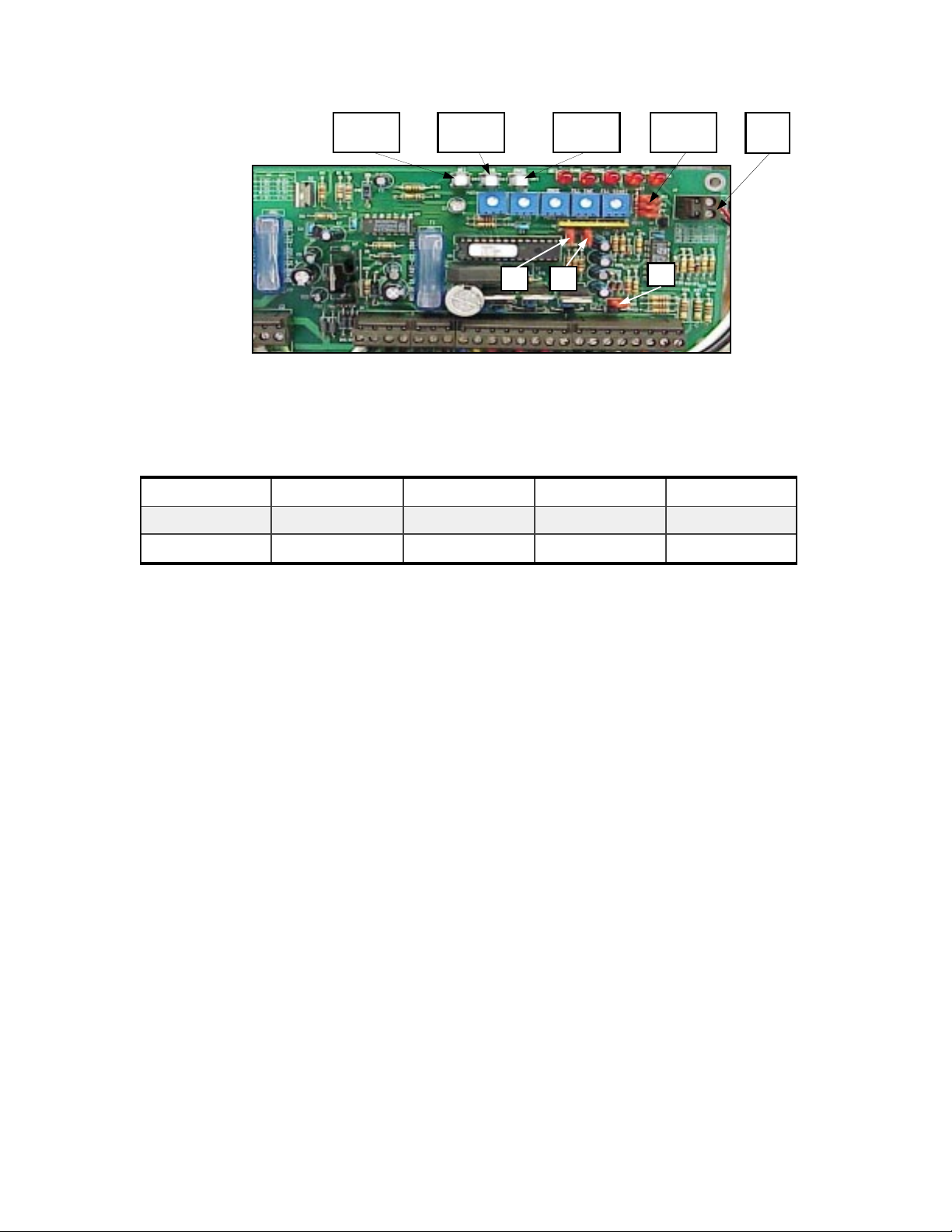
detergent
push button
sanitizer
push button
rinse push
button
JP4, JP5,
JP6
Buzzer
Conn.
JP1 JP2
JP3
JUMPER SETTINGS
Jumper settings will need to be done by authorized p ersonnel only. JP1 and JP2 control the wash cycle time.
Machine is factory set at 90 second wash cycle. Use table below to activate other wash cycles. Turn OFF main
power switch to change cycle times. Adjust Fill time, Fill start and other Pot's for proper operation.
JUMPER 72 SEC 90 SEC 120 SEC 360 SEC
JP1
JP2
OPEN OPEN CLOSED CLOSED
CLOSED OPEN OPEN CLOSED
NOTE: JP3 MUST BE CLOSED FOR PROPER OPERATION OF KLE 175GT.
JP3 MUST BE OPEN FOR PROPER OPERATION OF KLE 150GT.
JP4, JP5 and JP6 control proof of chemical delivery. They should be closed if proof of chemical delivery kit (P/
N 7501318 optional) is not installed. Machine can be ordered with proof of chemical delivery kit or kit can be
ordered separately.
PRIME CHEMICAL PUMP S
Each chemical pump can be primed simply by turning the delime switch to “ON” position during run time of
pump in wash cycle. This feature eliminates opening the control box lid to prime pumps using push button
prime switches.
CIRCUIT BOARD PUSH BUTTONS
Circuit board control done by authorized personnel only.
Detergent Push Button- Activities detergent pump if the main power switch is ON.
Sanitizer Push Button- Same as detergent
Rinse Push Button- Same as detergent
NORMAL OPERATION
1. Manually remove food debris from dishes, glasses, cups, etc. The better the pre-rinse the better the wash.
2. Place dishes, glasses, cups, etc. in dish rack. Do not stack dishes. Ensure glasses and cups are placed upside
down.
3. With the run power switch ON, close dish machine doors and machine will start. The wash cycle will take 90
seconds (120 or 72 seconds).
Page No. 4
(11/1001) Revision F, EO 4109 Part No. 9641606
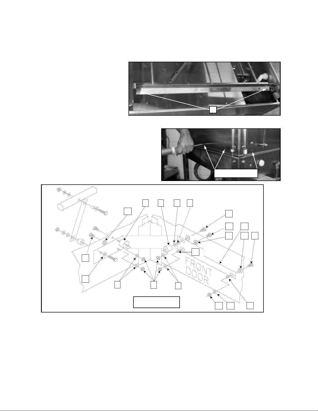
INLINE OR CORNER DOOR CONVERSION
Conversion from inline to corner can be done by changing the location o f the tray stop on the tray rails and installing door conversion bracket and screws in the accessory kit. Two 7/16 wrenches will be needed to make the conversion.
Conversion of the machine is easier
if done before tabling is attached.
Machines are factory set in the
inline configuration.
1. Remove the two (A) bolts/nuts
securing the tray rail stop located
on the tray rail and reposition to
A
desired configuration.
2. Make sure sump screen is in place over the pump
intake tube so no parts fall in to the pump! Remove
the two knockouts on the front door. One is located in
the center and the other is directly below the right
side door stop bumper. Remove one knockout directly
below bumper on right side door.
remove knockouts
9
9
1
5
1
2
INSIDE
4
VIEW
2
8
3
7
3
1
1
6
2
4 6 2
6
3. The accessory kit supplied with the dish machine contains the door strap and fasteners required to convert
the machine. Table below describes part provided for conversion in this kit.
Page No. 5
(11/01) Revision F, EO 4109 Part No. 9641606
 Loading...