

Knight Equipment KLE 150GTP Installation Manual
PUMP OUT DRAIN INSTALLATION INSTRUCTIONS
KLE 150GTP
P/N 9600032
Introduction:
The pump out drain option is designed to be used on our KLE 150GT dishwashers.
This optional kit is used in locations where floor drains are not used and uphill drains are required
to drain the dishwasher.
Tools needed:
1-Slotted screwdriver (Large)
2-Adjustable wrench
3-7/16” wrench
Parts included in this kit:
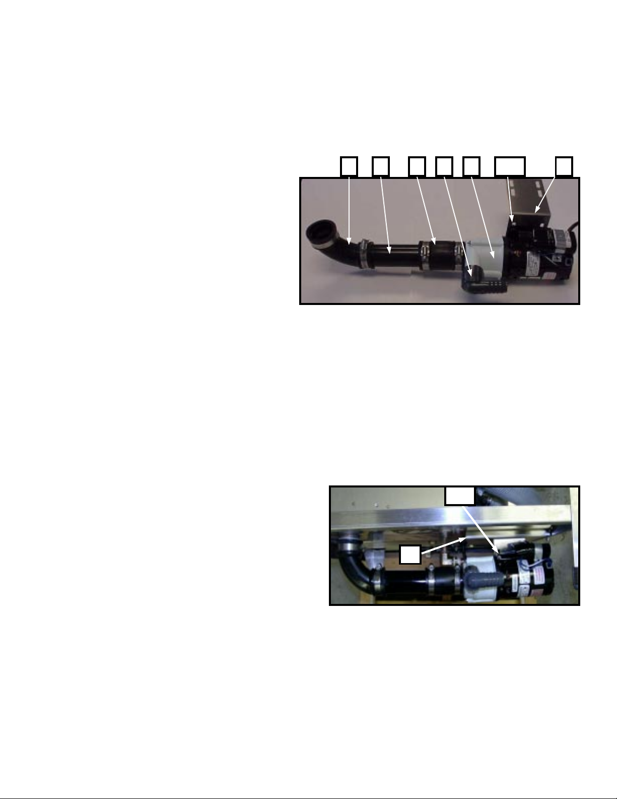
A- P/N 9600036, Drain pump/motor (1).
B- P/N 1600633, Elbow, 1” NPT X Barb (1).
C- P/N 1600631, Elbow, 1 1/2” Qwik ELL (1).
D- P/N 9600675, Drain pump bracket (1).
E- P/N 1900400, Strain relief body (2).
F- P/N 1900402, Strain relief locknut (2).
G- P/N 0800446, Pump suction tube (1).
H- P/N 9600423, ¼”-20 X ½” Hex bolt (4).
I- P/N 1400462, ¼”-20 Nylock (4).
J– P/N 2000757-1, Cable tie (5, Not Shown )
k– P/N 9600353 1 1/2” Pipe coupling (1) Fig. 1
L– P/N 9600740 Scrap Box Screen
A DH&IBKGC
INSTALLATION:
IMPORTANT NOTE:
- WATER LEVEL MUST BE ACCURATELY SET BEFORE INSTALLATION.
1- Drain dishmachine (If necessary) and switch off the wall breaker.
2- Disconnect the drain line from dishmachine’s scrap box discharge nipple.
Note: This step is for machines installed in field only!
3- Thread 1” elbow (B) on discharge port of pump as shown in Fig. 1.
4– Assemb le the Pipe coupling (K), suction tube (G) and Elbow
(C) as shown in Fig. 1 and install this assembly on the suction
port of the pump (A).
5- Using provided 1/4” nuts and bolts (H&I), install drain pump
bracket (D) On drain pump motor (A) as shown i n Fig. 1.
(HAND TIGHTEN ONLY AT THIS TIME).
N
F
6– Position the assembly behind the scrap box.
Insert the tip of scrap box discharge tube in elbow (C)
while matching slatted holes on pump bracket (D) with those
on electrical box slide base (N). Align and Secure assembly
with provided nuts and bolts (H&I) as shown in Fig. 2. Fig. 2
Care should be taken to route the drain hose (Not provided) straight
to the back of the machine, and up about two feet to the wall drain.
This will allow enough water to be returned back to the pump
head after drain cycle preventing possible cavatation.
All hose clamps and nuts can be tighten at this time.
H&I
P/N 9641614,Rev. c PAGE 1 OF 2

CONTINUED
7– Install the strain relief (E) using nut (F) on electrical
slide base (N) as shown. Guide the pump motor cable
up through the hole on strain relief and to control box
and secure cable with strain relief nut (F) as shown
in Fig. 3.
8– Continue guiding cable towards the back of control
box and tie it as needed on cable bundle with provided
cable ties. (Remove panel and slide control box forward
for easy access).
Make sure there is enough slack in the cable
so that the c ontrol box can easily be pulled in and out.
9– Pass the cable through hole on the back of control
box and secure with strain relief as shown in Fig. 4.
10–Locate the “pump out” block at the lower left side of
control board and connect:
Brown to L
Blue to N
Green/Yellow E
as shown in Fig. 5.
E&F
Fig. 3
E&F
Fig. 4
Dishmachine is now ready for installation. Refer to the dishwasher’s Fig. 5
Instruction manual for installation instructions.
L
If you have any questions or any comments about this or any other
KNIGHT
products, please call our customer service department
SCREEN
at (949) 595-4800
NOTE: PROVIDED SCRAP BOX SCREEN (L) MUST BE Fig.
6
PLACED OVER DISCHARGE HOLE INSIDE SCRAP BOX
TO PREVENT CLOGS AND PUMP DAMAGE! See Fig. 6.
DISCLAIMER
Knight Inc. does not accept responsibility for the mishandling, misuse,
or non-performance of the described items when used for purposes other
than those specified in the instructions. For hazardous materialinformation
consult label, MSDS, or Knight Inc.
WARRANTY
All stainless steel components have a three year limited warranty from date of purchase against manufacturers defects. The electronic control board has a two year warranty. Warranty
replacementfor component parts purchased by Knight are limited to warranty by the manufacturer. Warranty applies only to the replacement or repair of such parts when returned to factory with
a Knight Return Authorization (KRA) number, freightprepaid and found to be defective upon factory authorized inspection. Bearings and pump seals or rubber and synthetic rubber parts suchas
“O“-rings, diaphragms, squeeze tubing, and gaskets are considered expendable and are not covered under warranty. Warranty does not cover liability resulting from performance of this
equipmentnor the labor to replace this equipment. Product abuse or misuse voids warranty.
P/N 9641614, Rev. c PAGE 2 OF 2
 Loading...