

Knight Equipment KLE 150GT Installation Manual
'LVKPDFKLQH
./(*7
INSTRUCTION
AND
PART MANUAL
CONTENTS
INSTRUCTION MANUAL
INTRODUCTION Page 1
INSTALLATION Page 1
INITIAL OPERATION Page 2
TIME SETTINGS Page 3
JUMPER SETTINGS Page 4
CIRCUIT BOARD BUTTONS Page 4
NORMAL OPERATION Page 4
PROOF OF FLOW Page 5
PROOF OF FLOW Page 6
MAINTENANCE SCHEDULE Page 7
TROUBLESHOOTING Page 8
ELECTRICAL DIAGRAM Page 9
WARRANTY Page 10
PARTS MANUAL
ELECTRICAL BOX Page 12
DOOR Page 13
CABINET Page 14
SPRAY ARM Page 15
PLUMBING Page 16
DRAIN Page 17
Page 11
Headquarters: 20531 Crescent Bay Drive, Lake Forest, CA 92630 U.S.A. (949) 595-4800
Toronto, Ontario, Canada: 2283 Argentia Road, Unit 3, Mississauga, Ontario, Canada L5N 5Z2 (905) 542-2333
London England: Unit 15 Brunel Centre, Newton Road, Crawley, West Sussex, U.K. RH102UB (44) 1293-615570
Sydney, Australia: Unit 28, 317-321 Woodpark Road, Smithfield N.S.W., 2164 Australia (61)29.725.2588
Netherlands: 68 Marssteden, 7547 TD Enschede Holland 31.53.4285800
(8/01) Revision A EO 3986 Part No. 9641612
READ ALL INSTRUCTION BEFORE INSTALLATION
INTRODUCTION
The KLE 150 GT dishwasher is designed to provide years of excellent warewash results under many types of
conditions. This unit is configured as a push button start dishwasher. The dishwasher includes a three product
chemical dispenser which dispenses liquid detergent, rinse product, and a chemical sanitizer suitable for low
temperature (recommended 140 deg. F applications.) Options and additional features are also available. Contact
your nearest Knight representative for more details.
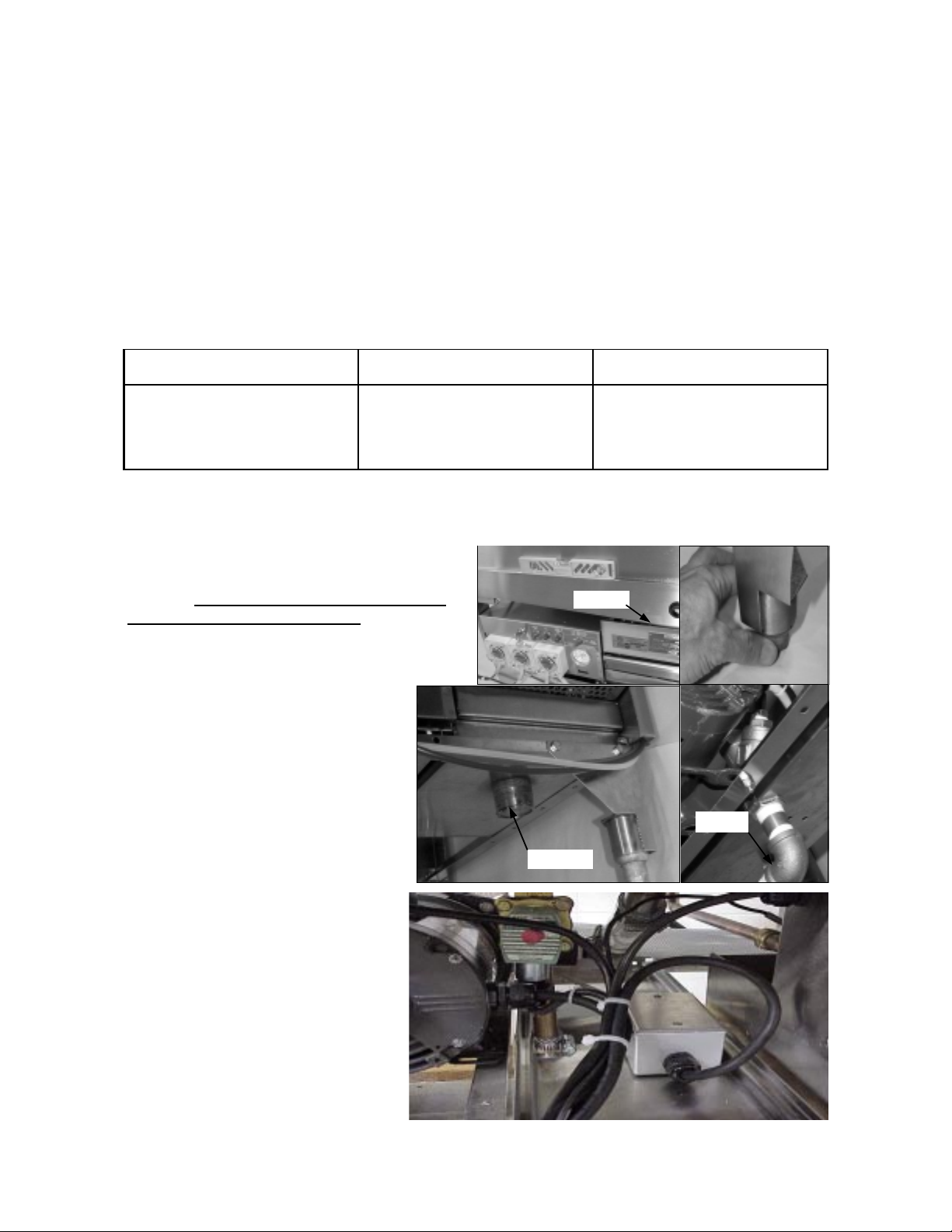
INSTALLATION - Caution –
1. Inspect the dishwasher upon initial receipt. Open the door and locate the accessory package inside the
dishwasher. Note that it includes a spray arm and other equipment required for installation.
2. Examine the spot where the dishwasher is to be operated. Insure that all electrical and plumbing connections have been considered for installation Parameters:
Electrical Water line Drain line
Access into electrical enclosure must be performed by authorized personnel.
- 120V 20 AMP circuit or
- 240V 10 AMP circuit (not field
convertible) connection box on
the tray stand.
20 psi flow pressure 140 deg. F
3/4” FPT lower left side 4 inches
above floor.
1-1/2” MPT on scrap accumulator
Lower right side, 6 inches above
floor.
3. Install detergent, sanitizer, and rinse tubing to the inlet side of the peristaltic pumps. Use the provided hose
clamp ties to secure tubing to squeeze tubing. If machine is ordered with Chem. alarm option, see page 6 for
instructions.
4. Place the dishwasher at the spot desired for normal
operation. Level the dishwasher using adjustable
Name plate
bullet feet at the bottom of the legs. Install spray
arm included in the accessory box.
5. Connect hot water supply line to the 3/4
FPT elbow at bottom-left of machine. Insure that water pressure is sufficient for fill
(approx. 10 GPM flow @ 20 psi.). Connect
drain to 1-1/2” MPT nipple on scrap accumulator to the lower right.
6. Make electrical connections (refer to
data plate for voltage and current ratings)
to the stationary conduit box located on the
1-1/2 MPT
3/4 FPT
stand tray behind electrical box. Remove
cover from stationary conduit box and
make connections (use appropriate wire
size) . Run all electri cal wire through suitable conduit and insure all connections are
made in accordance with local wiring
codes. It is recommended that the circuit
breaker carrying the dishwasher load have
NO OTHER ELECTRICAL DEVICES
and dishwasher is directly connected to
the circuit breaker.
(8/01) Revision A EO3986 Part No. 9641612
Page No. 1
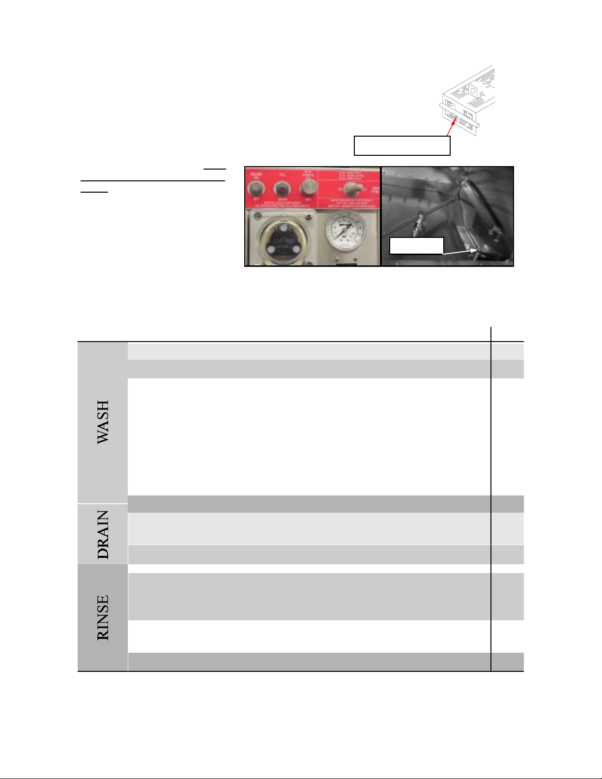
INITIAL OPERATION
1. Check pump intake screen for proper installation.
2. Start with all switches in the OFF position.
Hook tab under rod
3. Turn on main power switch. Open
and close door to reset the control
board. With door closed, flip up the fill
button to fill the dishwasher with fresh
140 deg. F water (120 deg. F min). Fill
until level with top of drain ball stem
(over flow point).
Water level
4. Press the RUN POWER switch and with door in closed position the machine will start to wash. Allow machine to run through one cycle and watch machine seque nce thro ugh the follo wing wash cycle: (90 seco nd cycle evaluated). 120 second cycle consists of 50 second wash, 15 second drain and 55 second rinse. See pages
3,4 and 9 for more details on 72, and 120 cycles.
TIME
1 second – wash pump motor turns on
3 seconds – detergent pump runs for adjusted period of time.
0
10
20
30
40
45 seconds – drain opens and machine drains for 15 seconds.
Adjustable 48 to 60 seconds – fresh water valve opens and rinses inside of dishwasher
(drain is still open)
50
60 seconds – drain closes and fill remains open for period of time to fill dish machine.
60
70 seconds – sanitizer and rinse pumps run for an adjustable period of time.
70
70 seconds – wash pump motor stops for three seconds then starts to “burp” the
machine.
80
90 seconds – machine will stop. This is the end of the wash cycle.
90
5. Machine is factory adjusted but may need to be adjusted to your location water pressure to operate
properly.
(8/01) Revision A EO 3986 Part No. 9641612
Page No. 2
TIME SETTINGS
Time settings will need to be done by authorized personnel only. The time settings for detergent pump, fresh
water fill, sanitizer pump, and rinse pump are done inside the control box using the single turn pots. T he pots
control the time duration of each of the listed components. Use the chart below to make settings.
POT
CONTROL
Detergent Pump
Pump motor relay sanitizer pump pot rinse pump pot Fill time pot Fill start pot
ACTIVE TIME
IN 90 SECONDS
at time = 3 seconds
Det. Pump pot
SPAN OF POT
ADJUSTMENT
2-30 seconds
FUSE 2A, 250V FUSE 2A, 250 V FUSE 1A, 250V FUSE 1 A, 250 V
TIME
COMMENTS
pot turns from 7 o'clock to 5 o'clock or 10 division.
Each division is 2.7 seconds. Pump flow is approximately 1.3 ml/sec.
Sani Pump
Rinse Pump
Fill Start
Fill Time
at time = 70 seconds
at time = 70 seconds
at time = 48 to 59
seconds
determined by fill start
0-15 seconds
0-15 seconds
0-11 seconds
10-42 seconds
pot turns 7 o'clock to 5 o'clock or 10 divisions. Each
division is 1.5 seconds. Pump flow is approximately
1.3 ml/sec.
pot turns 7 o'clock to 5 o'clock or 10 divisions. Each
division is 1.5 seconds. Pump flow is approximately
1.3 ml/sec.
fill start is activated during the fixed drain cycle (45
to 60 seconds) at the 7 o'clock setting time is 0 and
will start fill at 48 seconds in cycle. At the 5 o'clock
setting time is 11 seconds and will start fill at 59
seconds in cycle. Fill start is set according to water
pressure and the required time to rinse debris down
the drain. Normal setting at 20 psi flow pressure is 12
o'clock or 5.5 seconds.
begins at the setting of the fill start. Once fill start is
set the fill time determines the duration of time fresh
water solenoid valve remains open. 7 o'clock setting
time is 10 seconds, 5 o'clock setting time is 42 seconds. Adjust according to water pressure. Normal
setting at 20 psi flow pressure is 11 o'clock
or 15 seconds.
(8/01) Revision A EO3986 Part No. 9641612
Page No. 3
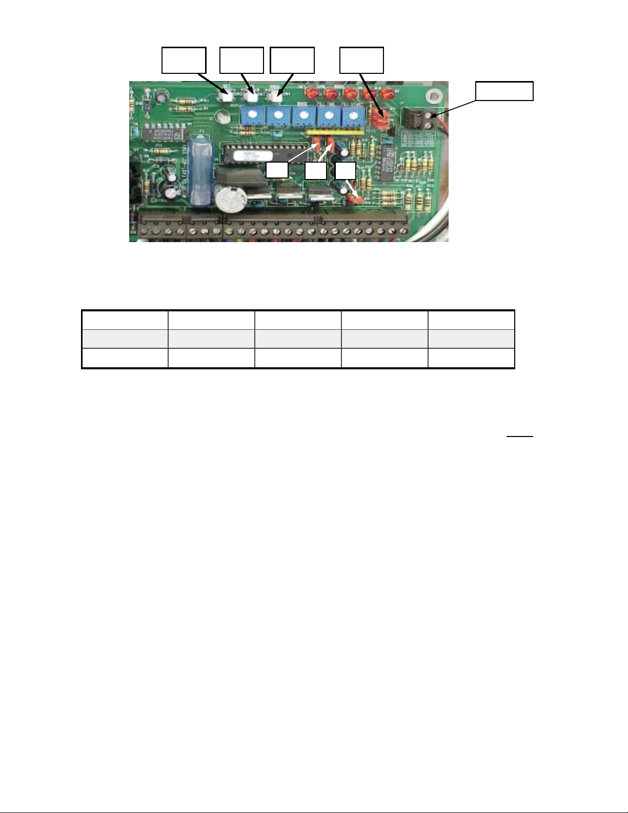
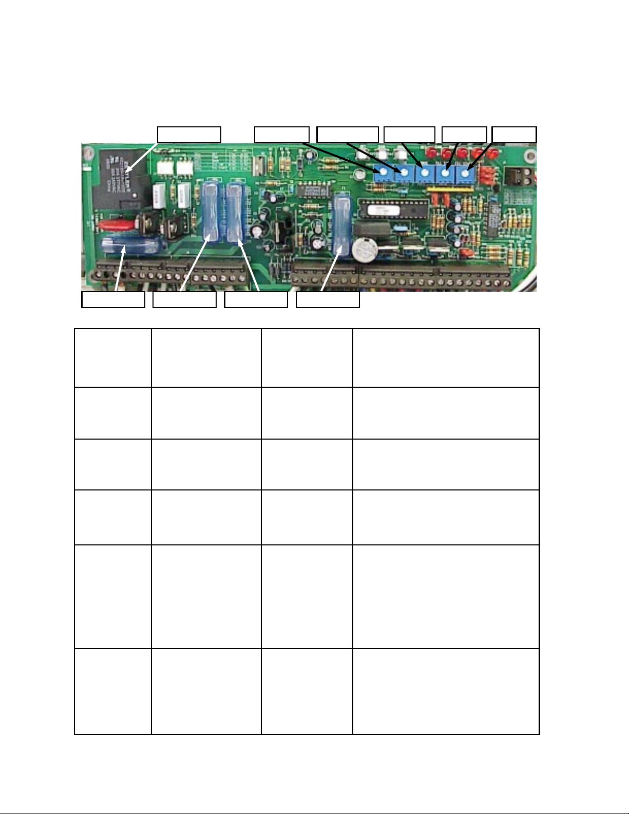
detergent
push button
sanitizer
push button
rinse push
button
JP4, JP5 JP6
ALARM CONN.
JP1 JP2
JP3
JUMPER SETTINGS
Jumper settings will need to be done by authorized personnel only. JP1 and JP2 control the wash cycle time.
Machine is factory set at 90 second cycle . Use table below to activate other wash cycles. Turn OFF main power
switch to change cycle times. Adjust pots for proper operation.
JUMPER 72 SEC 90 SEC 120 SEC 360 SEC
JP1
OPEN OPEN CLOSED CLOSED
JP2
NOTE:
JP3 MUST BE OPEN FOR PROPER OPERATION OF KLE 150GT.
CLOSED OPEN OPEN CLOSED
JP4,
JP3 MUST BE CLOSED FOR PROPER OPERATION OF KLE 175GT.
JP5 and JP6 control proof of detergent, sanitizer and rinse aid delivery respectively. They should be closed
if
proof of chemical delivery kit (P/N 7501318, optional) is not installed. Machine can be ordered with proof of
chemical delivery kit or kit can be ordered separately.
PRIME CHEMICAL PUMP S
Each chemical pump can be primed simply by turning the delime switch to “ON” position during run time of
pump in wash cycle. This feature elements opening the control box lid and holding chemical push button
switches to prime.
CIRCUIT BOARD PUSH BUTTONS
Circuit board control done by authorized personnel only.
Detergent Push Button- Activities detergent pump any time during wash cycle or delime cycle. Active when
main power switch is on. Can be used to prime detergent pump.
Sanitizer Push Button- Same as detergent
Rinse Push Button- Same as detergent
NORMAL OPERATION
1. Manually remove food debris from dishes, glasses, cups, etc. The better the pre-rinse the better the wash.
2. Place dishes, glasses, cups, etc. in dish rack. Do not stack dishes. Insure glasses and cups are placed upside
down.
3. With the main power switch ON, close dish machine door (door must be open and closed after each cycle to
reset the system) and press the run power switch, machine will start. The wash cycle will take 90 seconds (72 or
120 seconds).
(8/01) Revision A EO 3986 Part No. 9641612
Page No. 4
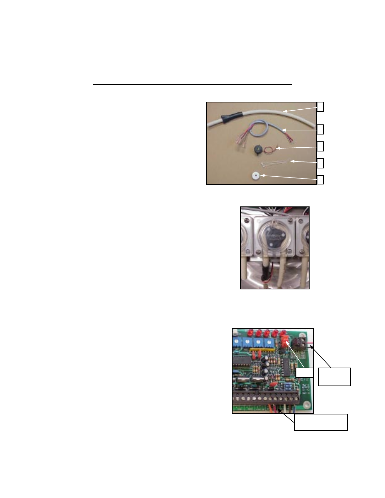
PROOF OF DELIVERY SYSTEM
(OPTION)
PUMP Page 18
DRAIN SYSTEM Page 13
Introduction:
PUMP Page 14
Proof of delivery system is designed to alert the dish washer operator of
Interruptions in flow of liquid chemicals (detergent sanitizer rinse aid).
This option can be ordered with your dishmachine orders or separately
using part number 7501318.
Parts included in this kit:
A- P/N 9640943, Tube probe assembly. (3)
B– P/N 9600027, Cable set assembly. (1)
C– P/N 1900598-1, Buzzer, piezzo, w/ 1 5” lead. (1)
D– P/N 0300121, Cable tie 3.5”. (3)
E– P/N 0300420, Hole plug. (1)
Fig. 1
Installation:
1- Turn main power switch and wall breaker to “OFF” position.
2– Plug all probe tube assembly connectors (A) in cable set
assembly (B) Spade connectors in the following wire color sequences:
Red/orange, white/ black and blue/brown for detergent , sani and
Rinse aid respectively.
3– Replace your pump’s existing squeeze tube with the tube probe assembly
as shown in Fig. 2.
Insert other end of cable set assembly in hole plug (E) and pass through the
Hole on the bottom of control box.
4– Make all chemical wire connections as shown .
Wire color sequences must be followed as in section 3.
Red /orange, detergent connections
White/ black, sanitizer connections.
Blue/ brown, rinse aid connections.
Jumpers JP4 (detergent), JP5 (sanitizer) and JP6 (rinse aid)
must be opened at this time to enable the alarm for each
Chemical.
Note: These jumpers are only opened if you are alarming
Chemicals. If you are alarming one chemical, only
The corresponding Jumper must be opned.
PROOF OF DELIVERY INSTALLATION INSTRUCTIONS
P/N 7501318
Fig. 2
JP4,5&6
Det, Sani and Rinse aid
alarm wire connections
Fig. 3
A
B
C
D
E
Buzzer conn.
JP4,5&6
.
(8/01) Revision A EC 3986 Part No. 9641612
Page No. 5
 Loading...