

Knight Equipment KHT-14B Service Manual
KHT-14B DISHWASHER
KHT-14B
High-Temp Dishmachine
OPERATION & SERVICE MANUAL
0900980 Rev: REL (04/13) Page 1 of 16

KHT-14B DISHWASHER
CONTENT
OVERVIEW ………………………………………………………… 3
INSTALLATION …………………………………………………… 4
LOCATION ……………………………………………………… 4
CONVERSION TO CORNER TYPE …………………………… 5
ELECTRICAL CONNECTION ………………………………… 6
WATER CONNECTION ………………………………… 8
OPERATION ………………………………………………………… 9
CONTROL PANEL ……………………………………………… 9
PREPARATION ………………………………………………… 10
DISH WASHING ………………………………………………… 10
CLEANING ……………………………………………………… 10
MAINTAINANCE …………………………………………………… 11
TROUBLE-SHOOTING …………………………………………… 11
TROUBLE-SHOOTING ………………………………………… 11
APPENDIX:1. WIRING DIAGRAMS
2. INSTALLATION GUIDE
3. DISPENSER BRACKET INSTALLATION GUIDE
0900980 Rev: REL (04/13) Page 2 of 16
KHT-14B DISHWASHER
KNIGHT HIGH-TEMP DISHMACHINE
Model KHT-14B
Installation,Operation & Maintenance
Please keep this manual for reference
OVERVIEW
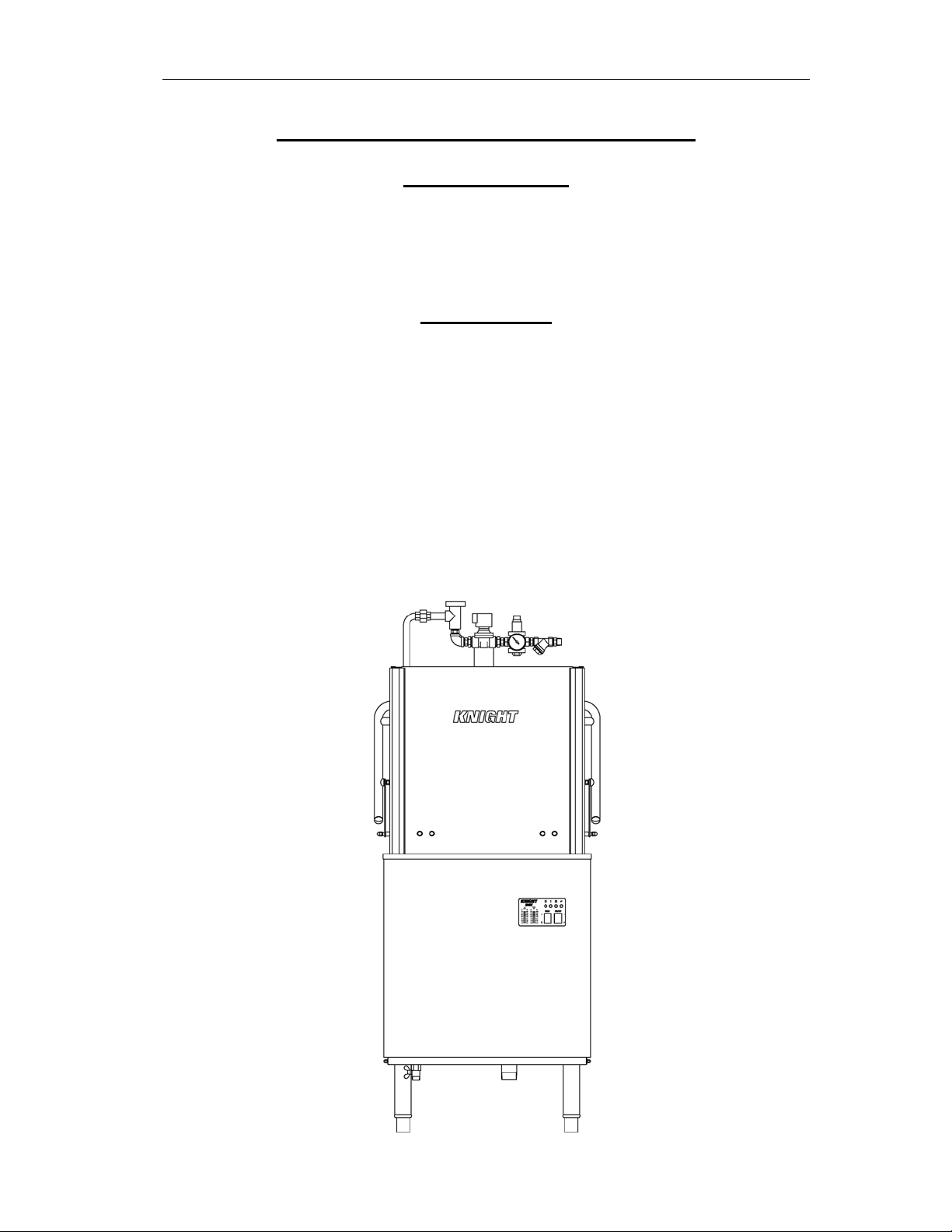
The Knight Dishmachine is a single rack automatic dishwashing machine. All three
doors lift for loading or unloading the rack. When the wash tank is filled up to the required
water level, as the door is closed, the machine will automatically run wash and rinse cycles.
If the tank water level is low, water will be automatically filled into the tank until the
normal water level is reached. Each time the door is closed, The KHT-14B starts to run
another complete cycle.
The working height to load the KHT-14B and attach a table is 34 inches or 860 mm.
The machine has a 2x7 KW rinse water booster and a 5 KW wash tank maintenance heater.
Incoming water is pressure reducing valve controlled with inline gauge and solenoid. All
operations of the KHT-14B are controlled from the front display panel
0900980 Rev: REL (04/13) Page 3 of 16
KHT-14B DISHWASHER
INSTALLATION
Before installation, please read the specification tag placed on the right hand side of
the machine, and make sure to verify the electrical power supply. Immediately after
unpacking the dishmachine, please examine the machine for any damage caused during
transportation. Please inform the supplier immediately of any damages.
Select the right place for installation
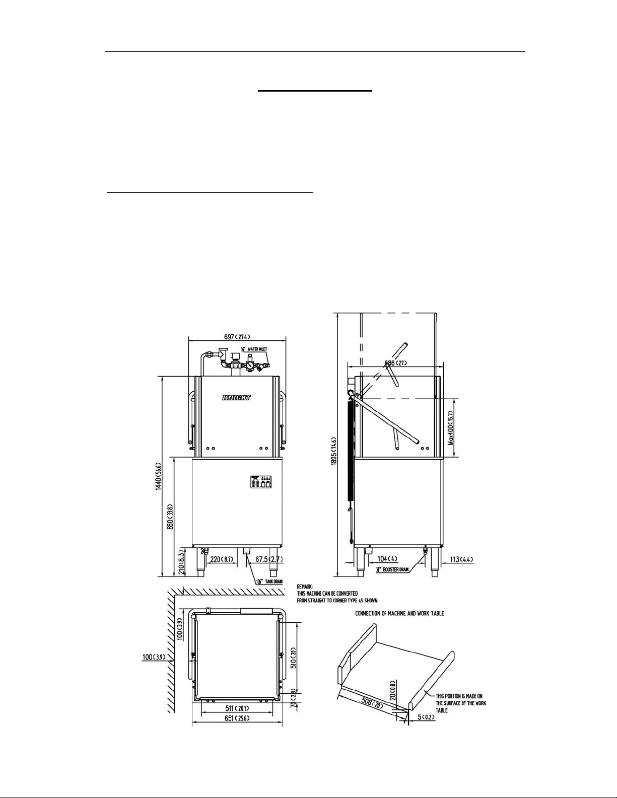
It is important to put the dishwasher at the right place for installation., Please consider
the connection of the power supply, water supply, drainage, S.S. working tables and
detergent dispenser (to be provided), as long as the required space for daily maintenance
and ceiling height for opening machine door. (See diagram 1) for dimension specification
(mm/inches)
0900980 Rev: REL (04/13) Page 4 of 16
KHT-14B DISHWASHER
Diagram 1
The KHT-14B must be horizontally placed for all electrical and water connections. To
reach the desired height level and maintain balance, turn the adjustable legs accordingly.
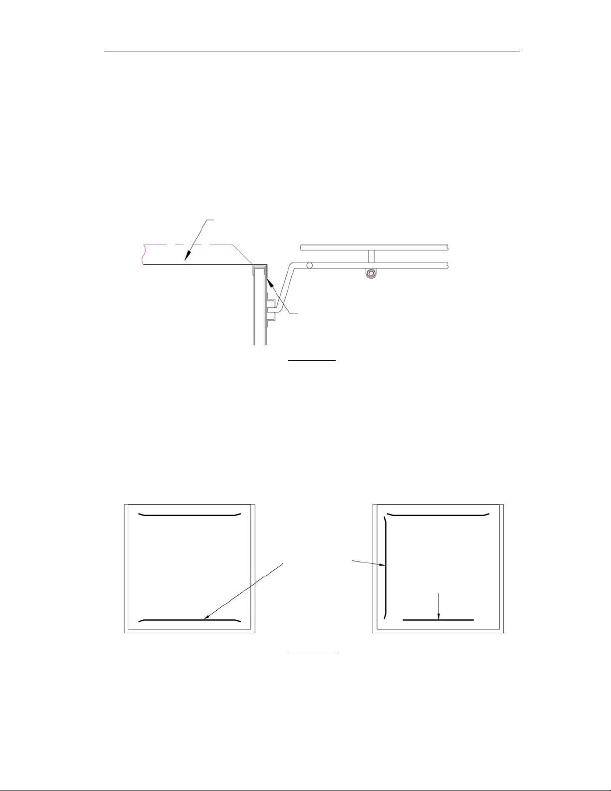
S.S. working tables should be hung on machine shall (see diagram 2), and sealed with
silicon to avoid leakage.
Local regulation may require the install of an exhaust hood or ventilator (not
3
provided). If needed, the required exhaust airflow should be at least 2.8m
/min.
DISH TABLE
SEAL TO PREVENT
LEAKAGE
Diagram 2
CONVERT FROM STRAIGHT-THROUGH TO CORNER OPERATION
For corner operat ion, remove the rack guide and baffle (Diagram.3) from the front,
of the rack guide and use screw to re-install the baffle in the front.
STRAIGHT-THROUGH
RACK GUIDE
CORNER
RE-INSTALL
BAFFLE HERE
Diagram 3
0900980 Rev: REL (04/13) Page 5 of 16
 Loading...