

Page 1
KNIGHT
Uniflow 1/2"
Bolted Plastic Pumps
Operating Instructions
Model Part Description
KAP-50SK 1600979 PVDF/Santoprene
KAP-50SP 1600968 Poly/Santoprene
KAP-50TP 1600945 Poly/TF
KAP-50TK 1600986 PVDF/TF
Rev: A (05/07)
Page 2

Read these instructions completely before installation and
start-up. It is the responsibility of the purchaser to retain
this manual for reference. Failure to comply with the recommendations stated in this manual could result in death,
serious bodily injury and/or property damage including
damage to the pump and/or voiding the factory warranty.
Correct pump selection is crucial to the pump operation.
Please assure pressure, temperature and chemical
compatibility before installation. Please consult Knight
Equipment, Engineering Specifications, Chemical Compatibility
Chart, or your distributor if in doubt about any application.
Operating Limitations for Various Elastomers
Neoprene 0°F (-18°C) to 200°F (93°C)
Buna-N 10°F (-12°C) to180°F (82°C)
Nordel -60°F (-51°C) to 280°F (138°C)
Viton -40°F (-40°C) to 350°F (176°C)
Polyurethane 10°F (-12°C) to 170°F (77°C)
XL TPE (Santoprene) -20°F ( -29°C) to 300°F (149°C)
FDA Hytrel -20°F ( -29°C) to 220°F (104°C)
Operating Limitations for Plastic Pumps
Kynar (PVDF) 10°F (-12°C) to 225°F (107°C)
Polypropylene 32°F (0°C) to 175°F (79°C)
Maximum temperature limits are based upon mechanical
stress only. Certain chemicals and environment conditions
significantly reduce maximum safe temperature limits.
Before pump operation, inspect all gasketed fasteners for
looseness caused by gasket creep. Re-torque all loose
fasteners to prevent leakage. Follow recommended torques
stated in this manual. Failure of the sealing components
creates the possibility of jetting or forceful discharge of
pumped material at a potentially harmful velocity.
Be certain that approved eye protection and protective
clothing are always worn during installation, service, mainte-
nance or when in the vicinity of the pump. Failure to follow
these recommendations may result in serious injury or death.
Never allow the piping system to be supported by the pump
manifolds or valve housing. The manifolds and valve housing
are not designed to support any structural weight and failure
of the pump may result.
Take action to prevent static sparking. Fire or explosion
can result, especially when handling flammable liquids. The
pump, piping, valves, containers, or other miscellaneous
equipment must be grounded.
Noise levels can exceed 85 dBA. Take precautions to prevent
personal injury due to excessive pump noise.
Do not exceed pump maximum operating pressure (found
on label and/or operating manual.)
Before doing any maintenance or repair on this pump,
be certain all pressure is completely vented for the pump,
suction, discharge, piping, and all other openings.
In the event of a diaphragm rupture, pumped material
may enter the air end of the pump and be discharged into
the atmosphere. If pumping a product that is hazardous
or toxic, the air exhaust must be piped to an appropriate
area for safe disposition.
SAFETY WARNINGS
40°F (4°C) to 220°F (105°C)
Page 2
Rev: A (05/07)
PTFE
Page 3
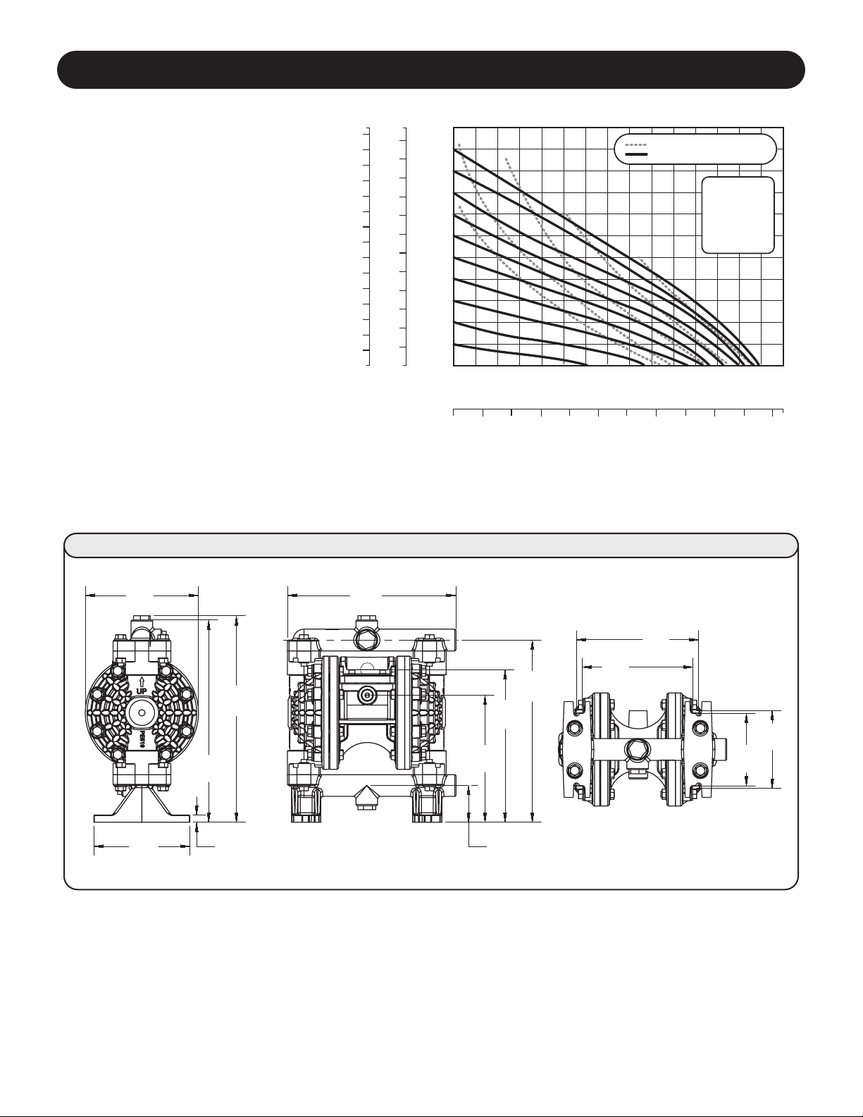
SPECIFICATIONS AND PERFORMANCE
Knight Uniflow
1/2" Bolted Plastic Pump
Flow Rate
Adjustable to . . . . . . . . 0-14 gpm (56 lpm)
Port Size
Suction . . . . . . . . . . . . . . . . . . . .50" NPTF
Discharge . . . . . . . . . . . . . . . . . .50" NPTF
Air Inlet. . . . . . . . . . . . . . . . . . 0.375" NPT
Air Exhaust . . . . . . . . . . . . . . 0.375" NPT
Suction Lift
Rubber . . . . . . . . . . . . . . 20' (6.09 m) Dry
Max. Particle Size (Diameter)
. . . . . . . . . . . . . . . . . . . 0.0625" (1.66 mm)
dB(A) Reading . . . . . . . . . . . . . 67.1 dB(A)
Shipping Weights
Polypropylene . . . . . . . . . . 6.8 lbs (3.1 kg)
Kynar. . . . . . . . . . . . . . . . . . 10 lbs (4.5 kg)
Acetal . . . . . . . . . . . . . . . . . 10 lbs (4.5 kg)
CCaauuttiioonn:: ddoo nnoott eexxcceeeedd 110000 ppssiigg
((66..99 bbaarr)) lliiqquuiidd oorr aaiirr ssuuppppllyy pprreessssuurree..
Meters Feet
Discharge Head in PSI
2106
0
100
90
80
70
60
50
40
30
20
10
0
240
220
200
180
160
140
120
100
80
60
40
20
0
75
70
65
60
55
50
45
40
35
30
25
20
15
10
5
0
128414
40
0
5 101520253035 455055
Capacity in Liters Per Minute
Capacity in U.S. Gallons Per Minute
Displacement Per Stroke, 0.03 Gal. (0.11 L)
4
8
12
16
2
AIR CONSUMPTION IN SCFM
AIR PRESSURE IN PSI
SCFM M3/HR
2 3.4
4 6.8
8 13.6
12 20.4
16 27.2
5.30
[134.6]
6.25
[158.8]
11.40
[289.6]
11.17
[283.7]
.40
[10.2]
2.03
[51.6]
8.43
[214]
10.06
[255.5]
7.01
[178.2]
9.30
[236.1]
6.75
[171.5]
6.12
[155.4]
4.30
[109.2]
4.00
[101.6]
Inches [mm]
Uniflow 1/2" Bolted Plastic Pump
Page 3
Rev: A (05/07)
.. ...........
PTFE.
(3.4 m) Dry
Page 4

Installation
The pump should be mounted in a vertical position.
In permanent installations, the pump should be
attached to plant piping using a flexible coupling on
both the intake and discharge connections to reduce
vibration to the pump and piping. To further reduce
vibration, a surge suppressor next to the pump may
be used.
Suction pipe size should be at least the same
diameter as the inlet connection size, even larger if
highly viscous fluid is to be pumped. If suction hose
is used, it must be of a non-collapsible reinforced
type. Discharge piping should be of at least the same
diameter as the discharge connection. It is critical,
especially on the suction side of the pump, that all
fittings and connections are air tight or pumping
efficiency will be reduced and priming will be difficult.
Make certain the air supply line and connections
and compressor are capable of supplying the
required pressure and volume of air to operate
the pump at the desired flow rate. The quality of the
compressed air source should be considered.
Air that is contaminated with moisture and dirt may
result in erratic pump performance and increased
maintenance cost as well as frequent process “down
time” when the pump fails to operate properly.
Pump Operation
The pump is powered by compressed air.
Compressed air is directed to the pump air chamber
by the main air valve. The compressed air is
separated from the fluid by a membrane called a
diaphragm. The diaphragm in turn applies pressure
on the fluid and forces it out of the pump discharge.
While this is occurring, the opposite air chamber
is de-pressurized and exhausted to atmosphere and
fluid is drawn into the pump suction. The cycle again
repeats, thus creating a constant reciprocating action
which maintains flow through the pump. The flow
is always in through the bottom suction connection
and out through the top discharge connection. Since
the air pressure acts directly on the diaphragms, the
pressure applied to the fluid roughly approximates
the air supply pressure supplied to the main air valve.
Manifold Bolts 35 in-lbs (4.0 N-m)
Water Chamber Bolts 60 in-lbs (6.8 N-m)
Diaphragm Plates — Rubber 75 in-lbs (8.5 N-m)
Air Valve Cap Screws 30 in-lbs (3.4 N-m)
Pump Size
Minimum Air Minimum Suction
Line Size Line Size
1/2" 1/2" 1/2"
INSTALLATION, OPERATION AND MAINTENANCE
Recommended Piping Connections
Torque Settings
DISCHARGE PIPING
AODD PUMP
SUCTION PIPING
AIR INLET PIPING
Shut Off
Valve
Shut Off
Valve
Flexible
Connection
Filter
Lubricator
Regulator
Air Exhaust
Muffler
Fluid
Inlet
Fluid
Discharge
Flexible
Connection
Shut Off
Valve
Union or Pipe Flange
Connection
Union or Pipe Flange
Connection
Flexible
Connection
Discharge
Pressure
Gauge
Suction
Pressure
Gauge
Page 4
Rev: A (05/07)
Diaphragm Plates ---PTFE 60-lbs (6.8 N-m)
Page 5

Mounting
Bolts
Fluid
Suction
Fluid
Discharge
Air
Supply
Surge
Suppresser
Shut Off
Valve
Pressure
Gauge
Flexible
Connection
Union or
Pipe Flange
Connection
Filter
Regulator
Air Exhaust
Muffler
Shut Off
Valve
Shut Off
Valve
Suggested Installation
In suction lift installations the pump datum is above the fluid
line. IMPORTANT: each pump has different lift capabilities.
Be sure to verify the lift capability of a particular pump before
installing it into a system.
A flooded suction installation has the pump datum line
below the fluid level. IMPORTANT: in flooded suction
installations the pressure at the fluid inlet of the pump
should never exceed 69 kPa (10 psi).
In a submerged application, the air exhaust port of the
pump must be ported above the fluid line. Be certain that the
fluid being pumped is compatible with the materials on both
the airside and the wetted side of the pump before the pump
is submerged.
A typical installation showing all the components that are
recommended in a system, including valves, pressure gauges,
air regulators, filters, and surge suppressors.
Flooded Suction Installation
Pump Datum
Fluid Discharge
Air Exhaust
Air Inlet
Suggested Submerged Installation
Suction Lift Installation
Pump Datum
Use of an air operated anti-siphon check valve for closed
system installations such as pressurized pipe is
recommended.
To maintain prime use a suction check valve inserted in
suction tube/pipe.
Drum
Check Valve
Air Operat ed
2 Way Valve
TYPICAL INSTALLATIONS
Page 5
Rev: A (05/07)
Page 6

EXPLODED VIEWS
55
54
64
63
48
52
50
49
65
38
40
45
46
47
35
37
25
34
22
48
33
18
20
19
6
8
21
53
9
2
3
5
4
7
1
11
Exploded View shows Rugged Diaphragm
35
37
4140
38
Description Kit Contents Part Number
Santoprene Diaphragms (2), Balls (4), Seat O-rings (4) 7600821
Main Diaphragms (2), Back-up Diaphragms (4), Balls (4), Seat O-rings (4) 7600822
REPAIR & MAINTENANCE KITS
PTFE DiaphragmsPTFE Diaphragms
Page 6
Rev: A (05/07)
Wet End Kit
PTFE, Buna
PTFE, Poly
Wet End Kit
Page 7

PARTS LIST
AIR VALVE ASSEMBLY
Item Description Quantity
Air Valve Assembly (Includes items 1-10)
1 Valve Body 1
2 Valve Spool 1
3 Valve Spool U-Cup 2
4 End Cap 2
5 End Cap O-Ring 2
6 Staple 2
7 Air Diverter 1
8 Valve Insert 1
9 Valve Gasket 1
10 Valve Screw 4
AIR END ASSEMBLY
Item Description Quantity
11 Center Section 1
18 Pilot Shaft 1
19 Pilot Shaft Spacer 5
20 Pilot Shaft O-Ring 6
21 Pilot Shaft Snap Ring 2
22 Shaft Retainer 2
25 Shaft Retainer Screw 4
33 Muffler 1
DIAPHRAGM ASSEMBLY
Item Description Quantity
34 Main Shaft O-Ring 2
35 Main Shaft 1
37 Inner Diaphragm Plate 2
38 Outer Diaphragm Plate 2
40 Diaphragm 2
41 Back-Up Diaphragm 2
WET END ASSEMBLY
Item Description Quantity
44 Water Chamber 2
45 Water Chamber Bolt 16
46 Water Chamber Washer 16
47 Water Chamber Nut 16
48 Valve Ball Cage 4
49 Valve Seat O-ring 4
50 Valve Seat 4
52 Valve Ball 4
53 Discharge Manifold 1
54 Inlet Manifold 1
55 Manifold Plugs 4
63 Manifold Bolts 8
64 Manifold Washers 8
65 Manifold Nuts 8
Page 7
Rev: A (05/07)
Page 8

©2007 IDEX Corporation KAP50-0307
20531 Crescent Bay Drive
Lake Forest, CA 92630
(949) 595-4800 • (800) 854-3764
Fax: (949) 595-4801
www.knightequip.com
Kynar® is a registered trademark of Penwalt Corp. Geolast® is a registered trademark of AES.
Distributed by:
Page 8
Rev: A (05/07)
 Loading...