

Knight Equipment ILCS EDGE Installation Manual
ILCS EDGE System
Installation Manual
0900885 Rev: A (12/06) Page 1 of 12

TABLE OF CONTENTS
System Overview..................................................................................................3
System Components............................................................................................3
System Diagram...................................................................................................4
Pre-Installation......................................................................................................5
Control Box & Power Supply Installation..............................................................5
Peristaltic Pump Installation..................................................................................5
Air Pump Installation.............................................................................................6
EDP Pump Installation..........................................................................................6
Manifold Installation (optional)..............................................................................7
Wiring Diagram..................................................................................................... 8
EDP Wiring Diagram ............................................................................................9
SIB Installation (optional)....................................................................................10
Label Change Procedure....................................................................................11
Warranty Information..........................................................................................12
Knight Locations.................................................................................................12
CAUTION: Wear protective clothing and eyewear when dispensing chemicals or
other materials. Observe safety handling instructions (MSDS) of chemical mfrs.
CAUTION: To avoid severe or fatal shock, always disconnect main power when
servicing the unit.
CAUTION: When installing any equipment, ensure that all national and local
safety, electrical, and plumbing codes are met.
Page 2 of 12 0900885 Rev: A (12/06)
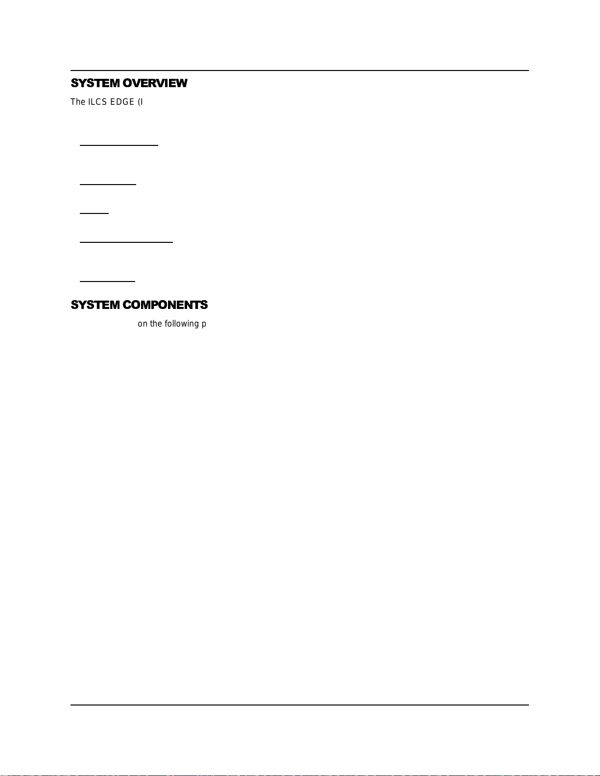
SYSTEM OVERVIEW
The ILCS EDGE (Intelligent Liquid Control System) is an automated chemical control system that accumulates critical
usage data of chemicals used for cleaning in food plants. Using the very latest concepts in process control
technology, the ILCS provides key benefits:
• Ease of Operation: ILCS EDGE eliminates messy drum pumps and the need to lift heavy drums of chemical that
can splash hazardous chemicals or spill on the ground. Pre-determined formulas can be dispensed into a gerry can
or other container.
• Cost Control: ILCS EDGE does more than just dispense chemicals. It gives all users the opportunity to get real
control of every aspect of day-to-day operation.
• Safety: The system limits the worker from coming in contact with concentrated cleaners by automatically
dispensing products into standard containers to use throughout the food plant.
• Environmental Safety: By dispensing directly to a product container the system limits spillage or waste. Chemical
concentrations and volumes are computer controlled to eliminate waste and guarantee the exact amount of product
used for each cleaning process.
• Main control: The ILCS EDGE control panel allows direct programming of the system at the keypad, and also
stores report information. PC interface to the control panel expands the data management capabilities.
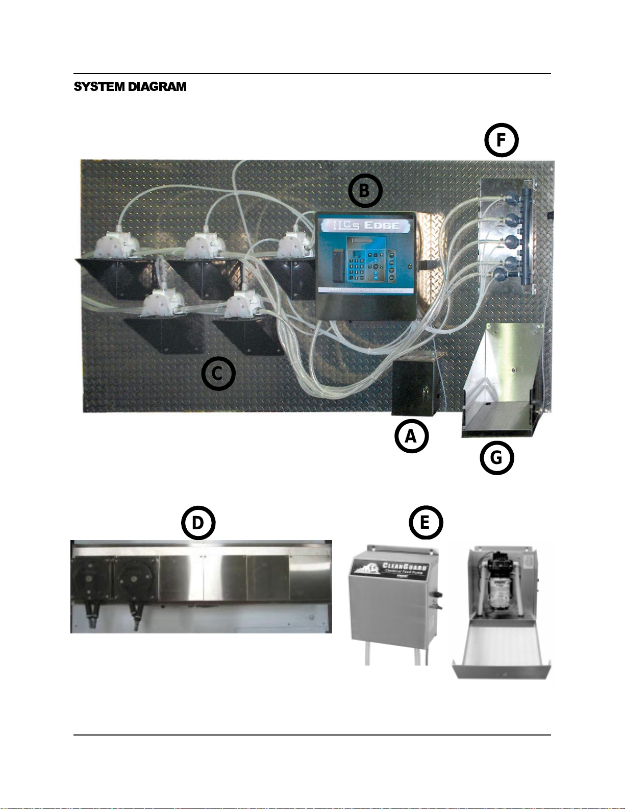
SYSTEM COMPONENTS
See the diagram on the following page for identification of the system components listed below. The available pump
options for the ILCS Edge system consist of Air Operated Diaphragm, Peristaltic, or Electric Diaphragm. If necessary,
various pump configurations can be utiliz ed to meet spe cif ic appl ication requirements.
(A) Power Supply: Isolates high voltage system operating power from the control box. The power supply box
contains a transformer and electrical noise filter for added protection.
(B) Control Box: Contains all system electronics and is the main command center for operation. The keypad allows
programming of all system operating parameters and entry of access codes for batch dispensing. Also housed
inside the control box are an air filter, air solenoids, and water flush valves. The system can be equipped with an
optional proximity card reader for convenient and secure access code entry.
(C) Air Operated Diaphragm Pumps: Available in 3/8” or 1/2” models. Use of air operated diaphragm pumps
provides high volume product delivery up to 14 GPM with a wide range of chemical compatibility. The pumps are
controlled via air solenoids in the system con trol box.
(D) Peristaltic Pumps: Available in 155 oz/min or 226 oz/min configurations. Use of peristaltic pumps provides easy
installation and maintenance, and does not require an air supply. The pumps are controlled via POB circuit board
inside the peristaltic pump cabinet.
(E) Electric Diaphragm Pumps: Available in 1.5 GPM and 3.2 GPM flow rates. These pumps are controlled via
POB circuit board. A separate POB Enclosure is available for this application, or the pumps can utilize extra
(unused) pump outputs on a POB board that is inside of a peristaltic pump cabinet.
(F) Flush Manifold (optional): Used for diluting and blending chemicals with water. The system has two separate
water flush solenoids that can be setup for single or dual manifold configuration. The use of dual manifolds
prevents cross-contamination of non-compatible chemicals. Air operated anti-siphon valves provide a positive
checkpoint to prevent siphoning of chemical and from water pushing back into chemical lines.
(G) Container Shelf (optional): Rugged stainless steel construction. The container shelf is large enough to hold up
to 5-gallon containers and comes with a wire rack and drip tray.
• SIB Enclosure (optional—not shown): For use with CIP (or external) pump applications. The SIB signal input
board provides an interface between the ILCS system and CIP (or external) pump activation signals. Connection
from the SIB to the ILCS control box is through low voltage data cable.
0900885 Rev: A (12/06) Page 3 of 12
SYSTEM DIAGRAM
F
B
C
D
A
G
E
Page 4 of 12 0900885 Rev: A (12/06)
 Loading...