

Knight Equipment FOAMGUARD II Installation Manual
INSTRUCTION MANUAL
INTRODUCTION
The Knight FoamGuard II Doorway Sanitizer is designed to lay down a blanket of sanitizing foam in doorways at
periodic timed intervals. The unit draws concentrated chemical from a local source, dilutes it with water at a predetermined rate, and produces a rich thick foam blanket on the floor that clings to the bottom of shoes or in forklift
treads. Features include:
Sophisticated timer – “Smart” timer allows sanitation levels to be set by traffic load
•
A menu walks you through the programming steps in simple English. So easy, first time users understand right
away and have no difficulties.
•
Spray intervals and durations are set by the plant’s shift times. Shifts can vary from day-to-day, or even schedule a
shutdown on weekends.
•
All the timing information from one day can be copied to another, making setup a snap.
•
The optional audible/visual alarm activates five seconds before the unit sprays, allowing people to step away
before their shoes get sprayed.
Two versions available
► Foam Tube Version – Simple design for maximum reliability. The mixing and foaming chamber has no moving
parts to wear out or break.
► Pump Driven Version – If low water pressure is a concern at the installation site, this version is for you.
Because a pump is used to push the liquids, low factory water pressure should never be a concern. Standard
with Santoprene elastomers, it is also available with Viton elastomers for aggressive chemicals.
•
Dilute on-the-fly – Both versions utilize concentrated sanitizer chemicals and dilute with water as needed. No need
to premix water and chemical in a bulky day tank that constantly needs to be refilled.
•
Secure – Once you set it, forget it. The Knight FoamGuard II cannot get tampered with. The programming menu is
password protected. All air and water adjustments are secure in a stainless steel enclosure under (user supplied)
lock and key to prevent tampering.
•
Sanitary and durable – The enclosures are constructed of powder coated stainless steel that won’t collect dirt and
debris and will look beautiful for years to come.
•
Flexible – One FoamGuard II unit will spray one double-door (one nozzle on each side), or two single doors (one
nozzle each), or one double-door and one adjacent single door (under many circumstances).
•
Modular – If you primarily need Foam Tube versions, you may wish to have a Pump Driven version on hand, in
case you run into an application where the water pressure is low. Because the units are modular, you only need to
stock a Pump Module to make the swap.
CAUTION: Wear protective clothing and eyewear when dispensing chemicals or
other materials. Observe safety handling instructions (MSDS) of chemical mfrs.
CAUTION: To avoid severe or fatal shock, always disconnect main power when
servicing the unit.
CAUTION: When installing any equipment, ensure that all national and local
safety, electrical, and plumbing codes are met.
CAUTION: Backflow preventer not supplied with FoamGuard II system. Please
check with local plumbing codes and install appropriate backflow preventer as
needed to prevent chemicals from contaminating water supply.
0900429 Rev: A (01/08) Page 1 of 8
Standard components
•
One wall-mounted unit – either the pump-driven version or the foam tube version. Each wall units consists of a
control module on the left, a hydraulic module on the right, both mounted on a common back plate.
•
Single chemical draw kit – check valve, metering tip kit, 6 foot pickup tube, ceramic weight, and foot valve.
•
Two discharge manifolds – foam nozzle mounted in an elbow attached to a 12 inch length of PVC pipe.
Optional components
•
Second chemical draw kit – allows for a second chemical to be educted simultaneously.
•
Alarm – Visual and audible signal the doorway is about to be foamed in 5 seconds.
INSTALLATION
(1) Mount the FoamGuard II doorway sanitizer to a wall near the doorway. The unit will supply sufficient foam for
one or two discharge nozzles (two supplied) under most conditions. This means you can cover one or two single
doors; or one double-door with a nozzle on each side. Each nozzle should be no more than 40 feet of line length
from the wall unit. See the installation diagram. on page 7
(2) Optionally, a third discharge nozzle can employed, if all three nozzles are within 20 feet of the wall unit. This is
useful where a people door is adjacent to a forklift door.
(3) Mount the supplied foam discharge ell(s) at the doorway about 1” – 2” off the floor, pointing the nozzle(s) in a flat
pattern to cover the distance across the floor.
(4) Connect the ¾” NPT foam outlet to the discharge ell(s) with ¾” pipe or tubing (user supplied). Pay attention to
line length to keep the foam spray balanced at each nozzle. Making an arch over a double door and placing a tee
in the middle of the arch will keep the spray from becoming uneven across a double-door. If a third nozzle is
used, a valve in the foam line (not supplied) may be needed to balance the foam delivery.
(5) If the optional strobe alarm is used, mount it where it can easily be seen by people standing in the path of the
foam spray.
(6) Connect electricity, water, and compressed air to unit (see wiring diagram and system specifications, pages 7
and 8). Follow all electric and plumbing codes, paying particular attention to backflow prevention requirements.
(7) If two chemicals are to be used at one time (for example, a non-foaming sanitizer and a foaming agent), then
install the appropriate optional dual chemical draw kit.
(8) Place the chemical concentrate(s) immediately beneath the wall unit. Using the metering tip chart below, install
the appropriate color tip(s) in the check valve(s). Remember, the chart will only give an estimate of dilution rates.
If exact dilutions are critical, measure the PPM of the foam and adjust the metering tip accordingly.
(9) Measure the chemical pickup tube and cut to length so that the bottom of the pickup tube is at the bottom of the
chemical container and not curling up. Attach to the barb of the check valve and secure with a zip tie.
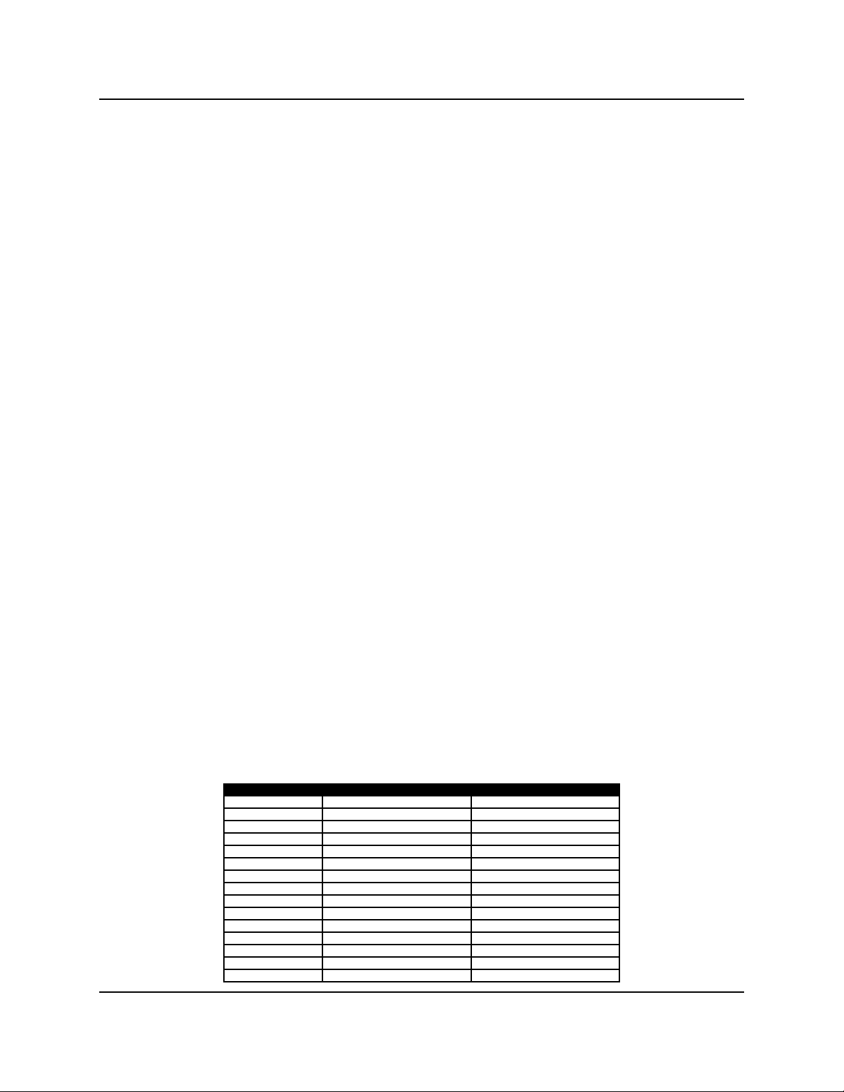
Metering tip dilution chart
Measured with water thin chemical. Results will vary with chemical viscosity and ambient temperature, so be sure to
measure actual dilutions and adjust accordingly.
Tip Color Chemical Flow, oz/gal Chemical to Water Ratio
White 22.10 1:5.8
Yellow 21.52 1:6.0
Pink 19.84 1:6.5
Dk Green 15.92 1:8.1
Black 13.27 1:9.6
Brown 9.15 1:14.2
Gray 6.72 1:19.3
Blue 5.71 1:22.9
Red 4.36 1:30.0
Peach 3.36 1:39.6
Lt Blue 2.56 1:54.1
Purple 1.97 1:70.1
Lt Green 1.38 1:99.6
Orange 0.57 1:228
Lt Brown 0.55 1:220
Page 2 of 8 0900429 Rev: A (01/08)

OPERATION
The cycle of operation begins when the unit is powered up, or when exiting the programming mode. The display will
show the current time and date on the top line, and the bottom line will show a 2 minute countdown until the unit
begins foaming. When the 2 minute countdown expires, the unit will begin foaming for the foam time set for the
current day and shift.
When the foam time is finished, the display will then show the time remaining (referred to as interval time) till the next
foaming activation. The system will continue in this manner throughout the shift. As soon as the next shift starts, the
system will count down for 5 seconds, and then will begin foaming for the foam time set for that shift.
Foam consistency is based on...
•
Type of Chemical – Some chemicals are naturally more foamy than others. Chemicals that don’t foam at all will
require the addition of a separate foaming agent (surfactant). The dual chemical draw kit is used in this case.
•
Chemical Dilution – Lightly dosed water may not foam well. Heavier concentrations of chemical-to-water may be
needed in order to create a thicker foam.
•
Air – This is adjusted with both the air pressure and air volume. The air pressure regulator is factory set at 40 psi.
You may need to increase or decrease this, depending upon your water pressure. [Not necessary with the Pump
Version.] The air volume is adjusted with the needle valve adjacent to the foam tube or foam tee. Opening the
valve lets in more air, tending to make drier foam. Closing the valve creates wetter foam.
•
Water Pressure – The air pressure needs to be lower than the water pressure to make foam. If the water pressure
is too low (under 35 psi) in the Foam Tube version, no amount of adjustments will make the foam dry and thick.
You need to install a Pump Version, or convert to Pump Version with a Pump Module.
Adjust the foam discharge ell(s) at the doorway to spray in a flat pattern to cover the distance across the floor(s).
BUTTON FUNCTIONS
ENTER: Allows access into programming mode, logs data from programming menus.
SCROLL: Exits programming mode, exits the current menu item, moves the cursor on the display.
UP: Acts as a “yes” response to menu prompts. Increases the selected number or day.
DOWN: Acts as “no” response to menu prompts. Decreases the selected number or day.
Important note: While programming, the scroll button is used to revert back to the previous selection. For example,
when you are making changes in a programming menu, press and hold the SCROLL button to go back to the original
menu prompt. From any menu prompt, you can press and hold the SCROLL button to exit the programming mode
and return to normal operation.
DEFAULT SETTINGS
The system will have the following default settings when shipped new from the factory, or after loading default
settings in the programming menus.
Shift times: 1 = 06:00 2 = 14:00 3 = 22:00
Foam times: Monday - Friday (all shifts) On for 30 seconds Off (interval time) for 30 minutes
Saturday & Sunday (all shifts) Zero on time Off (interval time) for 4 hours
Important note: Set the “on time” to zero for all days and shifts where you want the unit to be off.
0900429 Rev: A (01/08) Page 3 of 8
 Loading...