


KGCU483VSS00
KitchenAid KGCU483VSS00, KGCU484VSS00, KGCU467VSS00, KGCU482VSS00, KGCU462VSS00 Installation Guide
...
I_itc enAid _
INSTALLATION INSTRUCTIONS
30" (76.2 CM), 36" (91.4 CM) AND 48" (121.9 CM)
COMMERCIAL STYLE GAS COOKTOP S
INSTRUCTIONS D'INSTALLATION-
TABLES DE CUISSON A GAZ DE 30" (76,2 CM),
36" (91,4 CM) ET 48" (121,9 CM)-
MODELE COMMERCIAL
Table of Contents/Table des matieres ............................................................................. 2
iMPORTANT:
Installer: Leave installation instructions with the homeowner.
Homeowner: Keep installation instructions for future reference.
iMPORTANT :
Installateur : Remettre les instructions d'installation au propri6taire.
Propri6taire : Conserver les instructions d'installation pour r6f6rence ult6rieure.
W10271686C
TABLEOF CONTENTS
COOKTOP SAFETY ........................................................................ 3
INSTALLATION REQUIREMENTS ................................................ 4
Tools and Parts ............................................................................ 4
location Requirements ................................................................ 4
Electrical Requirements ............................................................... 7
Gas Supply Requirements ........................................................... 7
INSTALLATION INSTRUCTIONS .................................................. 8
Install Cooktop ............................................................................. 8
Install Optional Backguard ........................................................... 9
Make Gas Connection ................................................................. 9
Install Grill Grease Trays (on grill models) .................................. 10
Install Griddle ............................................................................. 11
Complete Installation ................................................................. 12
GAS CONVERSIONS .................................................................... 14
LP Gas Conversion .................................................................... 14
Natural Gas Conversion ............................................................. 16
STRIP CIRCUITS .......................................................................... 18
WIRING DIAGRAMS ..................................................................... 19
TABLEDES MATIERES
SECURITE DE LA TABLE DE CUISSON .................................... 21
EXIGENCES D'INSTALLATION ................................................... 22
Outillage et pieces ...................................................................... 22
Exigences d'emplacement ......................................................... 23
Specifications electriques .......................................................... 26
Specifications de I'alimentation en gaz ..................................... 26
INSTRUCTIONS D'INSTALLATION ............................................. 28
Installation de la table de cuisson .............................................. 28
Installation du dosseret facultatif ............................................... 28
Raccordement au gaz ................................................................ 28
Installation des plateaux a graisse du gril .................................. 30
Installation de la plaque a frire ................................................... 31
Achever I'installation .................................................................. 31
CONVERSIONS POUR CHANGEMENT DE GAZ....................... 33
Conversion pour I'alimentation au propane ............................... 33
Conversion pour I'alimentation au gaz naturel .......................... 36
SCHEMA DES CIRCUITS ............................................................. 38
SCHEMA DE C.&,BLAGE............................................................... 39
2
COOKTOP SAFETY
Your safety and the safety of others are very important.
We have provided many important safety messages in this manual and on your appliance. Always read and obey all safety
messages.
This is the safety alert symbol.
This symbol alerts you to potential hazards that can kill or hurt you and others.
All safety messages will follow the safety alert symbol and either the word "DANGER" or "WARNING."
These words mean:
You can be killed or seriously injured if you don't immediately
follow instructions.
You can be killed or seriously injured if you don't follow
instructions.
All safety messages will tell you what the potential hazard is, tell you how to reduce the chance of injury, and tell you what can
happen if the instructions are not followed.
WARNING: If the information in this manual is not followed exactly, a fire or explosion
may result causing property damage, personal injury or death,
- Do not store or use gasoline or other flammable vapors and liquids in the vicinity of this
or any other appliance,
- WHAT TO DO IF YOU SMELL GAS:
• Do not try to light any appliance.
• Do not touch any electrical switch.
• Do not use any phone in your building.
• Immediately call your gas supplier from a neighbor's phone. Follow the gas supplier's
instructions.
• If you cannot reach your gas supplier, call the fire department.
- Installation and service must be performed by a qualified installer, service agency or
the gas supplier,
WARNING: Gas leaks cannot always be detected by smell.
Gas suppliers recommend that you use a gas detector approved by UL or CSA.
For more information, contact your gas supplier.
If a gas leak is detected, follow the "What to do if you smell gas" instructions.
In the State of Massachusetts, the following installation instructions apply:
m Installations and repairs must be performed by a qualified or licensed contractor, plumber, or gasfitter qualified or licensed by
the State of Massachusetts.
m If using a ball valve, it shall be a T-handle type.
m A flexible gas connector, when used, must not exceed 3 feet.
INSTALLATION REQUIREMENTS
To order, see the "Assistance or Service" section of the Use and
t'i_ _:__!_: _, :_":*4_:_ Care Guide.
Gather the required tools and parts before starting installation, Check local codes and consult gas supplier, Check existing gas
supply and electrical supply, See "Electrical Requirements" and
Read and follow the instructions provided with any tools listed
here, "Gas Supply Requirements" sections,
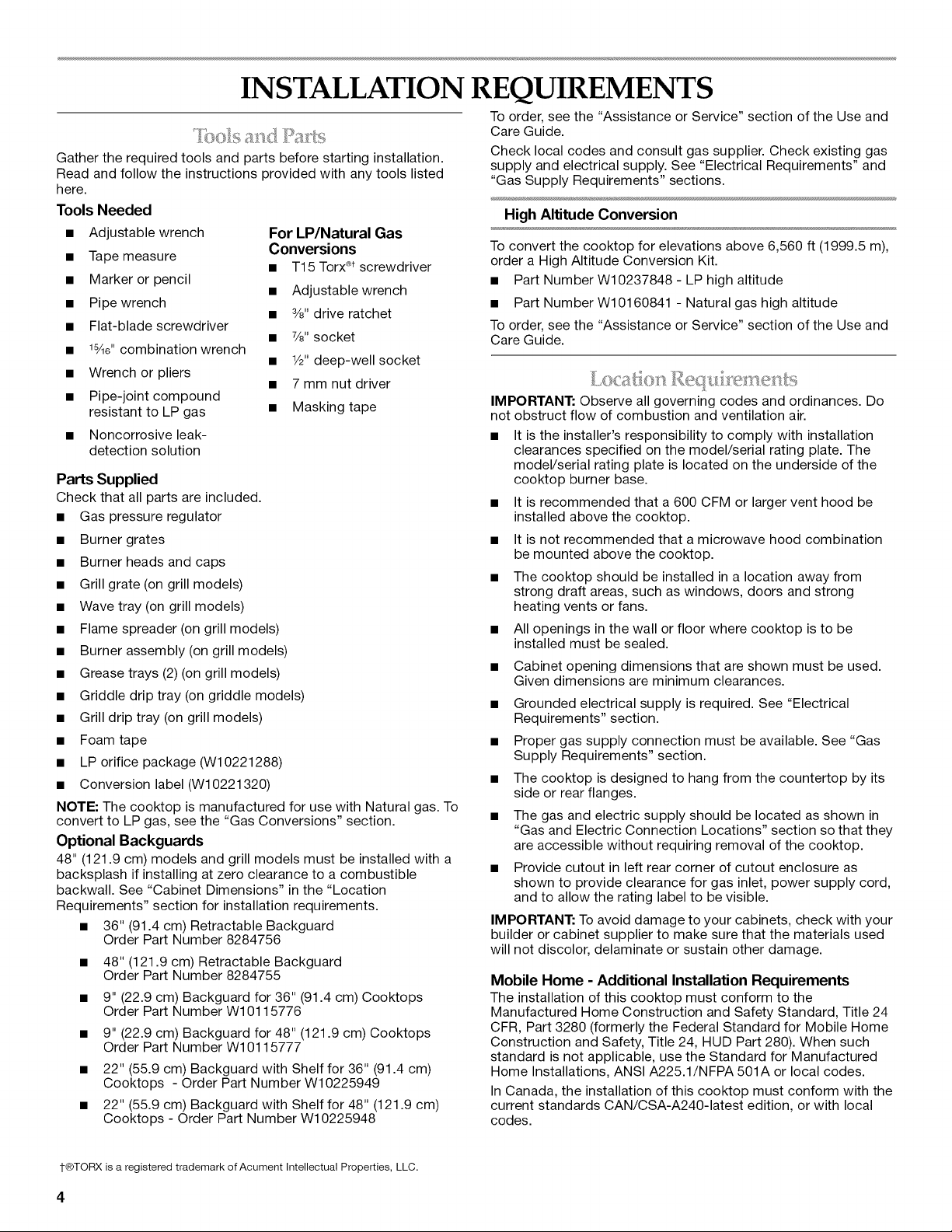
Tools Needed
• Adjustable wrench
• Tape measure
• Marker or pencil
• Pipe wrench
• Flat-blade screwdriver
• 18Ae"combination wrench
• Wrench or pliers
• Pipe-joint compound
resistant to LP gas
For LP/Natural Gas
Conversions
• T15 Torx_)tscrewdriver
• Adjustable wrench
• 3/8"drive ratchet
• 7/8"socket
• 1/2"deep-well socket
• 7 mm nut driver
• Masking tape
High Altitude Conversion
To convert the cooktop for elevations above 6,560 ft (1999.5 m),
order a High Altitude Conversion Kit.
• Part Number W10237848 - LP high altitude
• Part Number W10160841 - Natural gas high altitude
To order, see the "Assistance or Service" section of the Use and
Care Guide.
IMPORTANT: Observe all governing codes and ordinances. Do
not obstruct flow of combustion and ventilation air.
• Noncorrosive leak-
detection solution
Parts Supplied
Check that all parts are included.
• Gas pressure regulator
It is the installer's responsibility to comply with installation
clearances specified on the model/serial rating plate. The
model/serial rating plate is located on the underside of the
cooktop burner base.
It is recommended that a 600 CFM or larger vent hood be
installed above the cooktop.
• Burner grates
• Burner heads and caps
• Grill grate (on grill models)
• Wave tray (on grill models)
It is not recommended that a microwave hood combination
be mounted above the cooktop.
The cooktop should be installed in a location away from
strong draft areas, such as windows, doors and strong
heating vents or fans.
• Flame spreader (on grill models)
• Burner assembly (on grill models)
• Grease trays (2) (on grill models)
• Griddle drip tray (on griddle models)
• Grill drip tray (on grill models)
All openings in the wall or floor where cooktop is to be
installed must be sealed.
Cabinet opening dimensions that are shown must be used.
Given dimensions are minimum clearances.
Grounded electrical supply is required. See "Electrical
Requirements" section.
• Foam tape
• LP orifice package (W10221288)
• Conversion label (W10221320)
NOTE: The cooktop is manufactured for use with Natural gas. To
convert to LP gas, see the "Gas Conversions" section.
Optional Backguards
48" (121.9 cm) models and grill models must be installed with a
backsplash if installing at zero clearance to a combustible
backwall. See "Cabinet Dimensions" in the "Location
Requirements" section for installation requirements.
• 36" (91.4 cm) Retractable Backguard
Order Part Number 8284756
• 48" (121.9 cm) Retractable Backguard
Order Part Number 8284755
• 9" (22.9 cm) Backguard for 36" (91.4 cm) Cooktops
Order Part Number W10115776
• 9" (22.9 cm) Backguard for 48" (121.9 cm) Cooktops
Order Part Number W10115777
22" (55.9 cm) Backguard with Shelf for 36" (91.4 cm)
Cooktops - Order Part Number W10225949
22" (55.9 cm) Backguard with Shelf for 48" (121.9 cm)
Cooktops - Order Part Number W10225948
• Proper gas supply connection must be available. See "Gas
Supply Requirements" section.
• The cooktop is designed to hang from the countertop by its
side or rear flanges.
• The gas and electric supply should be located as shown in
"Gas and Electric Connection Locations" section so that they
are accessible without requiring removal of the cooktop.
• Provide cutout in left rear corner of cutout enclosure as
shown to provide clearance for gas inlet, power supply cord,
and to allow the rating label to be visible.
IMPORTANT: To avoid damage to your cabinets, check with your
builder or cabinet supplier to make sure that the materials used
will not discolor, delaminate or sustain other damage.
Mobile Home - Additional Installation Requirements
The installation of this cooktop must conform to the
Manufactured Home Construction and Safety Standard, Title 24
CFR, Part 3280 (formerly the Federal Standard for Mobile Home
Construction and Safety, Title 24, HUD Part 280). When such
standard is not applicable, use the Standard for Manufactured
Home Installations, ANSI A225.1/NFPA 501A or local codes.
In Canada, the installation of this cooktop must conform with the
current standards CAN/CSA-A240-1atest edition, or with local
codes.
t®TORX is a registered trademark of Acument Intellectual Properties, LLC.
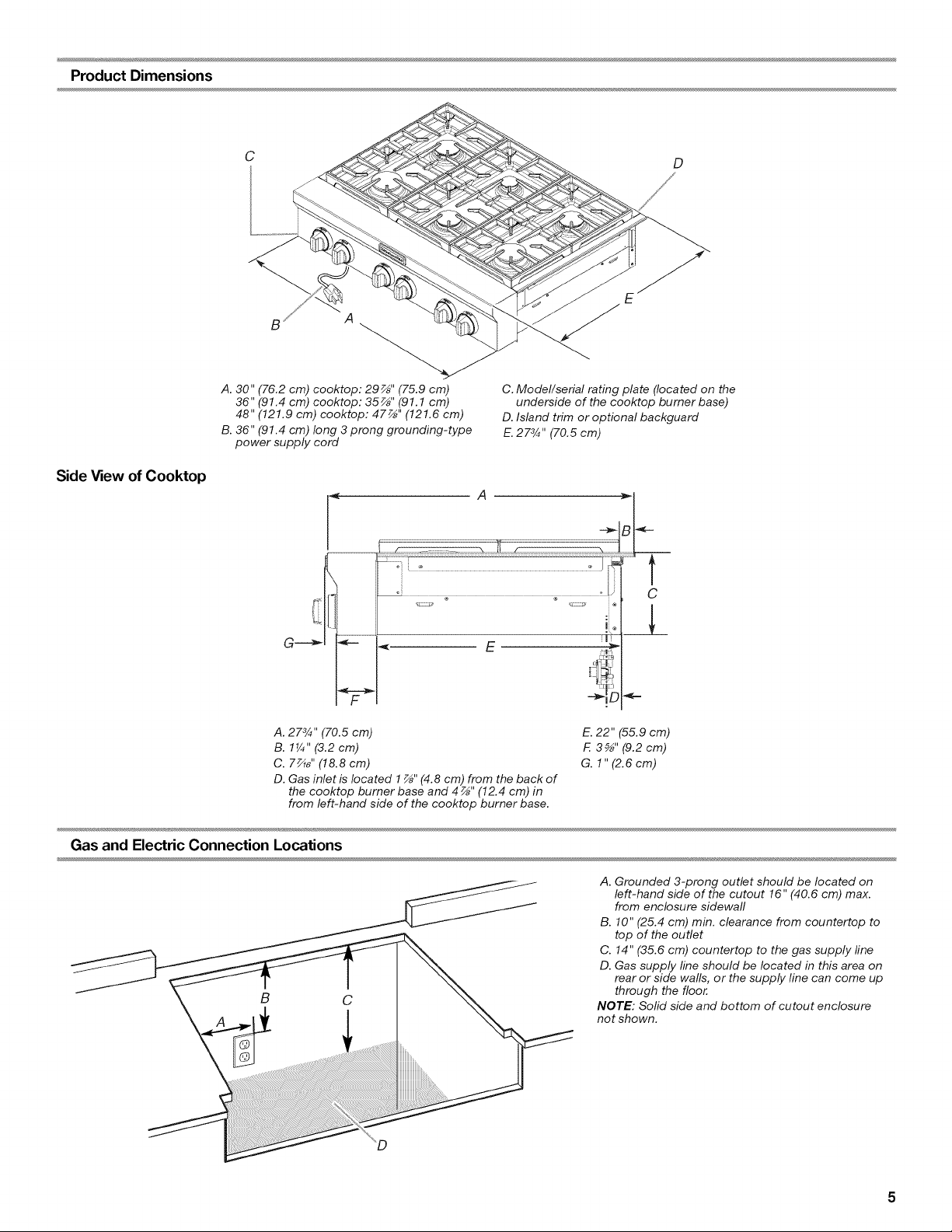
Product Dimensions
Side View of Cooktop
C
B
A
A. 30" (76.2 cm) cooktop: 29_" (75.9 cm)
36" (91.4 cm) cooktop: 35_" (91.1 cm)
48" (121.9 cm) cooktop: 47_" (121.6 cm)
B. 36" (91.4 cm) long 3 prong grounding-type
power supply cord
D
C. Model/serial rating plate (located on the
underside of the cooktop burner base)
D. Island trim or optional backguard
E.2 7%" (70.5 cm)
A
A. 27%" (70.5 cm)
B. 1_" (3.2cm)
C. 7_" (18.8 cm)
D. Gas inlet is located 1 _" (4.8 cm) from the back of
the cooktop burner base and 4 _" (12.4 cm) in
from left-hand side of the cooktop burner base.
E. 22" (55.9 cm)
F. 35_ '' (9.2cm)
G. 1"(2.6cm)
Gas and Electric Connection Locations
B
C
I
A. Grounded 3-prong outlet should be located on
left-hand side of the cutout 16" (40.6 cm) max.
from enclosure sidewall
B. 10" (25.4 cm) min. clearance from countertop to
top of the outlet
C. 14" (35.6 cm) countertop to the gas supply fine
D. Gas supply line should be located in this area on
rear or side walls, or the supply line can come up
through the floor.
NOTE: Solid side and bottom of cutout enclosure
not shown.
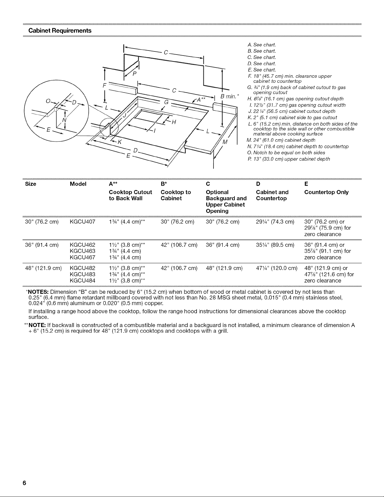
Cabinet Requirements
A. See chart.
B. See chart.
C. See chart.
D. See chart.
E. See chart.
F. 18" (45.7 cm) min. clearance upper
cabinet to countertop
G. ¾" (1.9 cm) back of cabinet cutout to gas
opening cutout
H. 6z_''(16.1 cm) gas opening cutout depth
I. 127/2'' (31.7 cm) gas opening cutout width
J. 22 ¼" (56.5 cm) cabinet cutout depth
K. 2" (5.1 cm) cabinet side to gas cutout
L. 6" (15.2 cm) min. distance on both sides of the
cooktop to the side wall or other combustible
material above cooking surface
M. 24" (61.0 cm) cabinet depth
N. 7_" (18.4 cm) cabinet depth to countertop
O. Notch to be equal on both sides
P. 13" (33.0 cm) upper cabinet depth
Size Model A** B* C D E
Cooktop Cutout Cooktop to Optional Cabinet and Countertop Only
to Back Wall Cabinet Backguard and Countertop
Upper Cabinet
Opening
30" (76.2 cm) KGCU407 1%" (4.4 cm)** 30" (76.2 cm) 30" (76.2 cm) 29W' (74.3 cm) 30" (76.2 cm) or
297/8'' (75.9 cm) for
zero clearance
36" (91.4 cm) KGCU462 11/2'' (3.8 cm)** 42" (106.7 cm) 36" (91.4 cm)
KGCU463 1%" (4.4 cm)
KGCU467 1%" (4.4 cm)
48" (121.9 cm)
351¼'' (89.5 cm) 36" (91.4 cm) or
357/8'' (91.1 cm) for
zero clearance
KGCU482 11/2'' (3.8 cm)** 42" (106.7 cm) 48" (121.9 cm) 471¼'' (120.0 cm) 48" (121.9 cm) or
KGCU483 1%" (4.4 cm)** 477/8'' (121.6 cm) for
KGCU484 11/2"(3.8 cm)** zero clearance
*NOTES: Dimension "B" can be reduced by 6" (15.2 cm) when bottom of wood or metal cabinet is covered by not less than
0.25" (6.4 mm) flame retardant millboard covered with not less than No. 28 MSG sheet metal, 0.015" (0.4 mm) stainless steel,
0.024" (0.6 mm) aluminum or 0.020" (0.5 mm) copper.
If installing a range hood above the cooktop, follow the range hood instructions for dimensional clearances above the cooktop
surface.
**NOTE: If backwall is constructed of a combustible material and a backguard is not installed, a minimum clearance of dimension A
+ 6" (15.2 cm) is required for 48" (121.9 cm) cooktops and cooktops with a grill.
6
£:i',l@CI (;.a/_,.@;]!
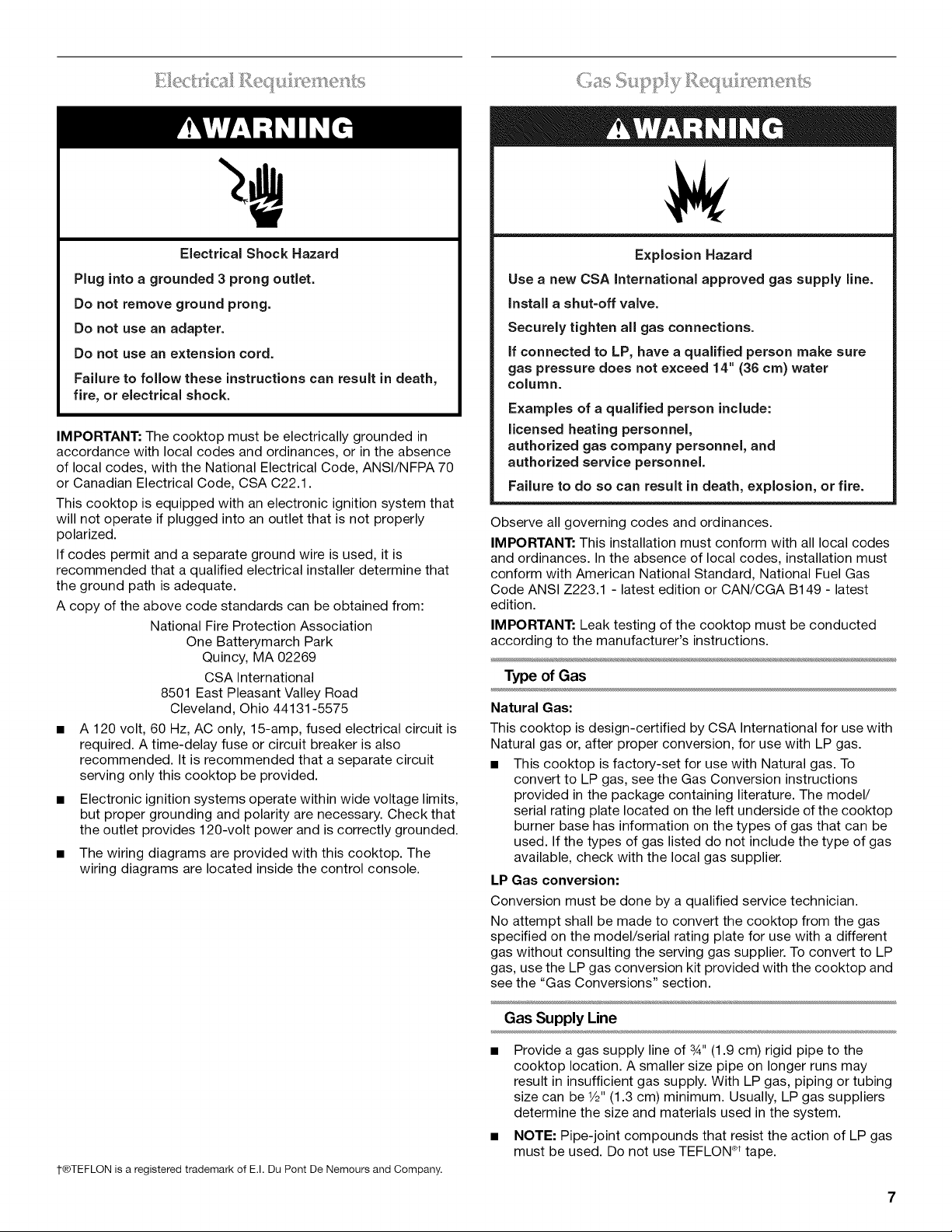
Electrical Shock Hazard
Plug into a grounded 3 prong outlet.
Do not remove ground prong.
Do not use an adapter.
Do not use an extension cord.
Failure to follow these instructions can result in death,
fire, or electrical shock.
IMPORTANT: The cooktop must be electrically grounded in
accordance with local codes and ordinances, or in the absence
of local codes, with the National Electrical Code, ANSI/NFPA 70
or Canadian Electrical Code, CSA C22.1.
This cooktop is equipped with an electronic ignition system that
will not operate if plugged into an outlet that is not properly
polarized.
If codes permit and a separate ground wire is used, it is
recommended that a qualified electrical installer determine that
the ground path is adequate.
A copy of the above code standards can be obtained from:
National Fire Protection Association
One Batterymarch Park
Quincy, MA 02269
CSA International
8501 East Pleasant Valley Road
Cleveland, Ohio 44131-5575
• A 120 volt, 60 Hz, AC only, 15-amp, fused electrical circuit is
required. A time-delay fuse or circuit breaker is also
recommended. It is recommended that a separate circuit
serving only this cooktop be provided.
• Electronic ignition systems operate within wide voltage limits,
but proper grounding and polarity are necessary. Check that
the outlet provides 120-volt power and is correctly grounded.
• The wiring diagrams are provided with this cooktop. The
wiring diagrams are located inside the control console.
"" _f ; _'_'_ /s /s ,/ _ ..................
Explosion Hazard
Use a new CSA International approved gas supply line.
install a shut=off valve.
Securely tighten all gas connections.
if connected to LP, have a qualified person make sure
gas pressure does not exceed 14" (36 cm) water
column.
Examples of a qualified person include:
licensed heating personnel,
authorized gas company personnel, and
authorized service personnel.
Failure to do so can result in death, explosion, or fire.
Observe all governing codes and ordinances.
IMPORTANT: This installation must conform with all local codes
and ordinances. In the absence of local codes, installation must
conform with American National Standard, National Fuel Gas
Code ANSI Z223.1 - latest edition or CAN/CGA B149 - latest
edition.
IMPORTANT: Leak testing of the cooktop must be conducted
according to the manufacturer's instructions.
Type of Gas
Natural Gas:
This cooktop is design-certified by CSA International for use with
Natural gas or, after proper conversion, for use with LP gas.
• This cooktop is factory-set for use with Natural gas. To
convert to LP gas, see the Gas Conversion instructions
provided in the package containing literature. The model/
serial rating plate located on the left underside of the cooktop
burner base has information on the types of gas that can be
used. If the types of gas listed do not include the type of gas
available, check with the local gas supplier.
LP Gas conversion:
Conversion must be done by a qualified service technician.
No attempt shall be made to convert the cooktop from the gas
specified on the model/serial rating plate for use with a different
gas without consulting the serving gas supplier. To convert to LP
gas, use the LP gas conversion kit provided with the cooktop and
see the "Gas Conversions" section.
t®TEFLON is a registered trademark of E.I. Du Pont De Nemours and Company.
Gas Supply Line
Provide a gas supply line of 3A,,(1.9 cm) rigid pipe to the
cooktop location. A smaller size pipe on longer runs may
result in insufficient gas supply. With LP gas, piping or tubing
size can be 1/2"(1.3 cm) minimum. Usually, LP gas suppliers
determine the size and materials used in the system.
NOTE: Pipe-joint compounds that resist the action of LP gas
must be used. Do not use TEFLON ®ttape.
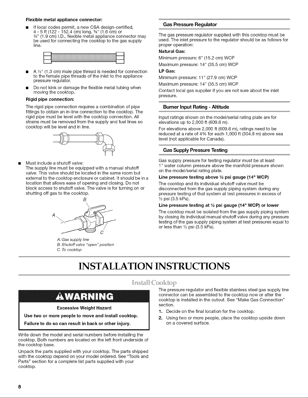
Flexible metal appliance connector:
If local codes permit, a new CSA design-certified,
4 - 5 ft (122 - 152.4 cm) long, %" (1.6 cm) or
3_,,(1.9 cm) I.D., flexible metal appliance connector may
be used for connecting the cooktop to the gas supply
line.
• A 1/2"(1.3 cm) male pipe thread is needed for connection
to the female pipe threads of the inlet to the appliance
pressure regulator.
• Do not kink or damage the flexible metal tubing when
moving the cooktop.
Rigid pipe connection:
The rigid pipe connection requires a combination of pipe
fittings to obtain an in-line connection to the cooktop. The
rigid pipe must be level with the cooktop connection. All
strains must be removed from the supply and fuel lines so
cooktop will be level and in line.
Must include a shutoff valve:
The supply line must be equipped with a manual shutoff
valve. This valve should be located in the same room but
external to the cooktop enclosure or cabinet. It should be in a
location that allows ease of opening and closing. Do not
block access to shutoff valve. The valve is for turning on or
shutting off gas to the cooktop.
B
A _
A. Gas supply fine
B. Shutoff valve "open" position
C. To cooktop
Gas Pressure Regulator
The gas pressure regulator supplied with this cooktop must be
used. The inlet pressure to the regulator should be as follows for
proper operation:
Natural Gas:
Minimum pressure: 6" (15.2 cm) WCP
Maximum pressure: 14" (35.5 cm) WCP
LP Gas:
Minimum pressure: 11" (27.9 cm) WCP
Maximum pressure: 14" (35.5 cm) WCP
Contact local gas supplier if you are not sure about the inlet
pressure.
Burner Input Rating - Altitude
Input ratings shown on the model/serial rating plate are for
elevations up to 2,000 ft (609.6 m).
For elevations above 2,000 ft (609.6 m), ratings need to be
reduced at a rate of 4% for each 1,000 ft (304.8 m) above sea
level (not applicable for Canada).
Gas Supply Pressure Testing
Gas supply pressure for testing regulator must be at least
1" water column pressure above the manifold pressure shown
on the model/serial rating plate.
Line pressure testing above 1/2psi gauge (14" WCP)
The cooktop and its individual shutoff valve must be
disconnected from the gas supply piping system during any
pressure testing of that system at test pressures in excess of
1/2psi (3.5 kPa).
Line pressure testing at 1/2psi gauge (14" WOP) or lower
The cooktop must be isolated from the gas supply piping system
by closing its individual manual shutoff valve during any pressure
testing of the gas supply piping system at test pressures equal to
or less than 1/2psi (3.5 kPa).
INSTALLATION INSTRUCTIONS
Excessive Weight Hazard
Use two or more people to move and install cooktop.
Failure to do so can result in back or other injury.
Write down the model and serial numbers before installing the
cooktop. Both numbers are located on the left front underside of
the cooktop base.
Unpack the parts supplied with your cooktop. The parts shipped
with the cooktop depend on your model ordered. See "Tools and
Parts" section for a complete list parts supplied with your
cooktop.
The pressure regulator and flexible stainless steel gas supply line
connector can be assembled to the cooktop now or after the
cooktop is installed in the cutout. See "Make Gas Connection"
section.
1. Decide on the final location for the cooktop.
2. Using two or more people, place the cooktop upside down
on a covered surface.
8
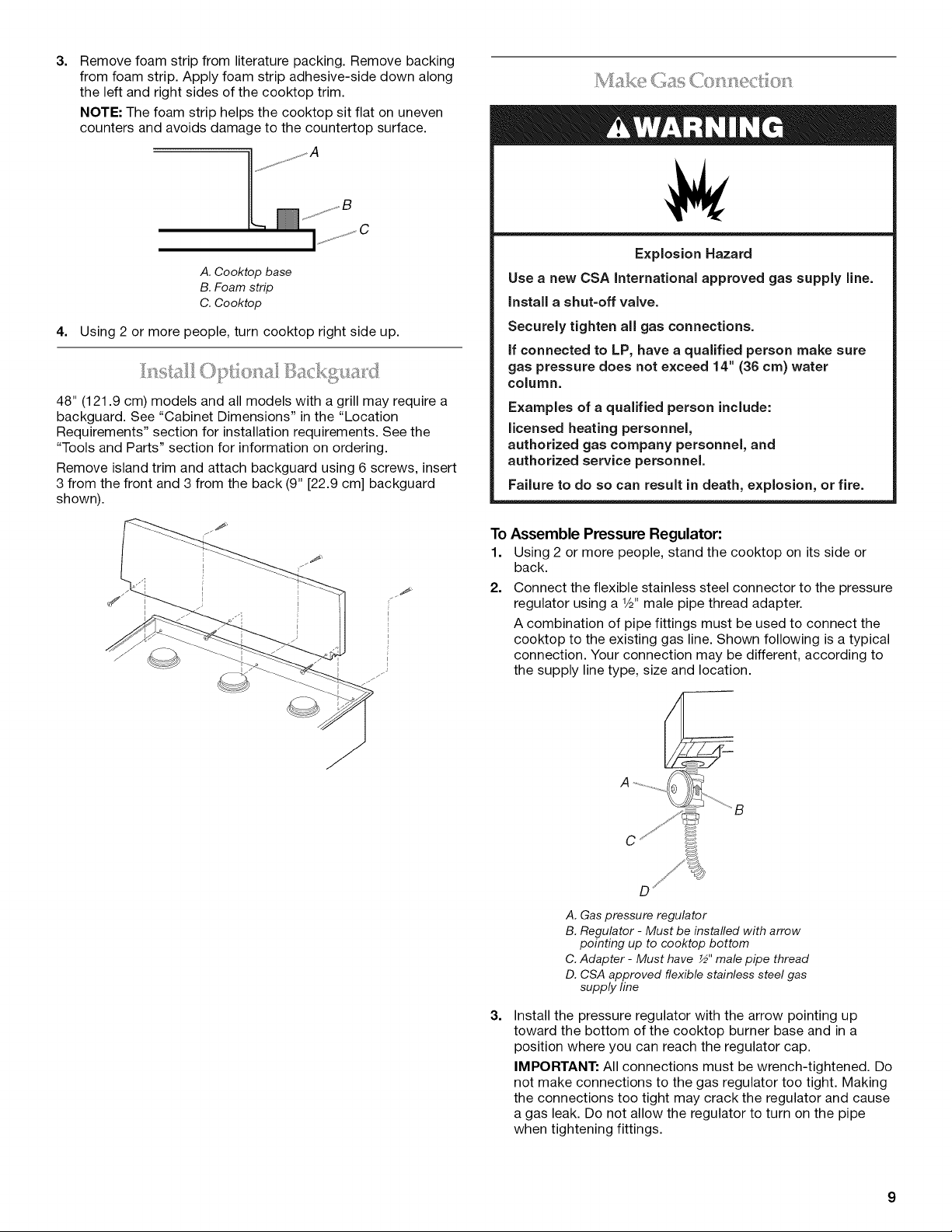
3=
Remove foam strip from literature packing. Remove backing
from foam strip. Apply foam strip adhesive-side down along
the left and right sides of the cooktop trim.
NOTE: The foam strip helps the cooktop sit flat on uneven
counters and avoids damage to the countertop surface.
A. Cooktop base
B. Foam strip
C. Cooktop
4. Using 2 or more people, turn cooktop right side up.
__,_.............,_,...........
48" (121.9 cm) models and all models with a grill may require a
backguard. See "Cabinet Dimensions" in the "Location
Requirements" section for installation requirements. See the
"Tools and Parts" section for information on ordering.
Remove island trim and attach backguard using 6 screws, insert
3 from the front and 3 from the back (9" [22.9 cm] backguard
shown).
Explosion Hazard
Use a new CSA International approved gas supply line.
Install a shut-off valve.
Securely tighten all gas connections.
if connected to LP, have a qualified person make sure
gas pressure does not exceed 14" (36 cm) water
column.
Examples of a qualified person include:
licensed heating personnel,
authorized gas company personnel, and
authorized service personnel.
Failure to do so can result in death, explosion, or fire.
To Assemble Pressure Regulator:
1. Using 2 or more people, stand the cooktop on its side or
back.
2. Connect the flexible stainless steel connector to the pressure
regulator using a V2" male pipe thread adapter.
A combination of pipe fittings must be used to connect the
cooktop to the existing gas line. Shown following is a typical
connection. Your connection may be different, according to
the supply line type, size and location.
3=
C
A. Gas pressure regulator
B. Regulator - Must be installed with arrow
pointing up to cooktop bottom
C. Adapter - Must have ½" male pipe thread
D. CSA approved flexible stainless steel gas
supply line
Install the pressure regulator with the arrow pointing up
toward the bottom of the cooktop burner base and in a
position where you can reach the regulator cap.
IMPORTANT: All connections must be wrench-tightened. Do
not make connections to the gas regulator too tight. Making
the connections too tight may crack the regulator and cause
a gas leak. Do not allow the regulator to turn on the pipe
when tightening fittings.
4=
Use only pipe-joint compound made for use with Natural and
LP gas. Do not use TEFLON ®tape.
You will need to determine the fittings required depending on
your installation.
Place cooktop into the countertop cutout.
NOTE: Check that the front edge of the cooktop is parallel to
the front edge of the countertop. If repositioning is needed,
lift entire cooktop up from cutout to avoid scratching the
countertop.
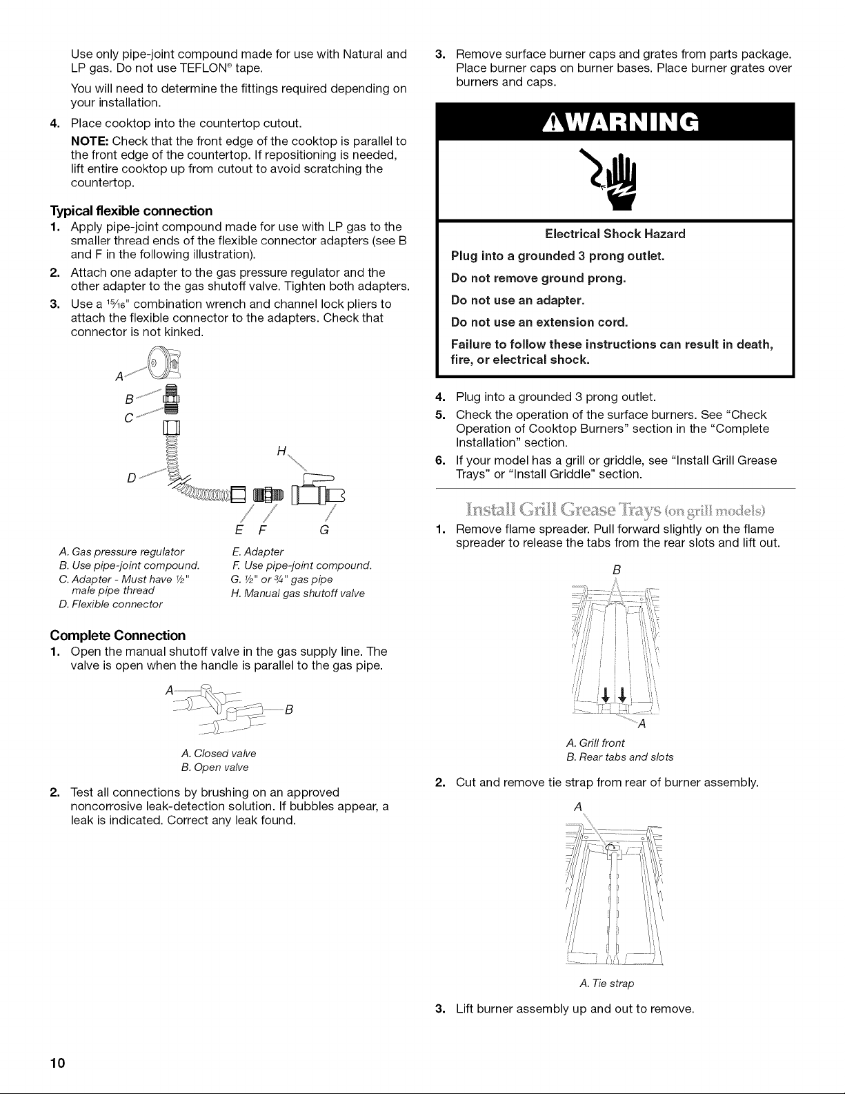
Typical flexible connection
1. Apply pipe-joint compound made for use with LP gas to the
smaller thread ends of the flexible connector adapters (see B
and F in the following illustration).
2. Attach one adapter to the gas pressure regulator and the
other adapter to the gas shutoff valve. Tighten both adapters.
3. Use a lS/le"combination wrench and channel lock pliers to
attach the flexible connector to the adapters. Check that
connector is not kinked.
A
/,/ •
E F G
A. Gas pressure regulator
B. Use pipe-joint compound.
C. Adapter - Must have Y2"
male pipe thread
D. Flexible connector
E.Adapter
F Use pipe-joint compound.
G. Y2"or 3/4"gas pipe
H. Manual gas shutoff valve
Complete Connection
1. Open the manual shutoff valve in the gas supply line. The
valve is open when the handle is parallel to the gas pipe.
3=
Remove surface burner caps and grates from parts package.
Place burner caps on burner bases. Place burner grates over
burners and caps.
Electrical Shock Hazard
Plug into a grounded 3 prong outlet.
Do not remove ground prong.
Do not use an adapter.
Do not use an extension cord.
Failure to follow these instructions can result in death,
fire, or electrical shock.
4. Plug into a grounded 3 prong outlet.
5. Check the operation of the surface burners. See "Check
Operation of Cooktop Burners" section in the "Complete
Installation" section.
6. If your model has a grill or griddle, see "Install Grill Grease
Trays" or "Install Griddle" section.
1=
Remove flame spreader. Pull forward slightly on the flame
spreader to release the tabs from the rear slots and lift out.
B
2=
A. Closed valve
B. Open valve
Test all connections by brushing on an approved
noncorrosive leak-detection solution. If bubbles appear, a
leak is indicated. Correct any leak found.
2=
..........................A
A.Grill front
B.Reartabs and slots
Cut and remove tie strap from rear of burner assembly.
A
A. Tiestrap
3. Lift burner assembly up and out to remove.
10
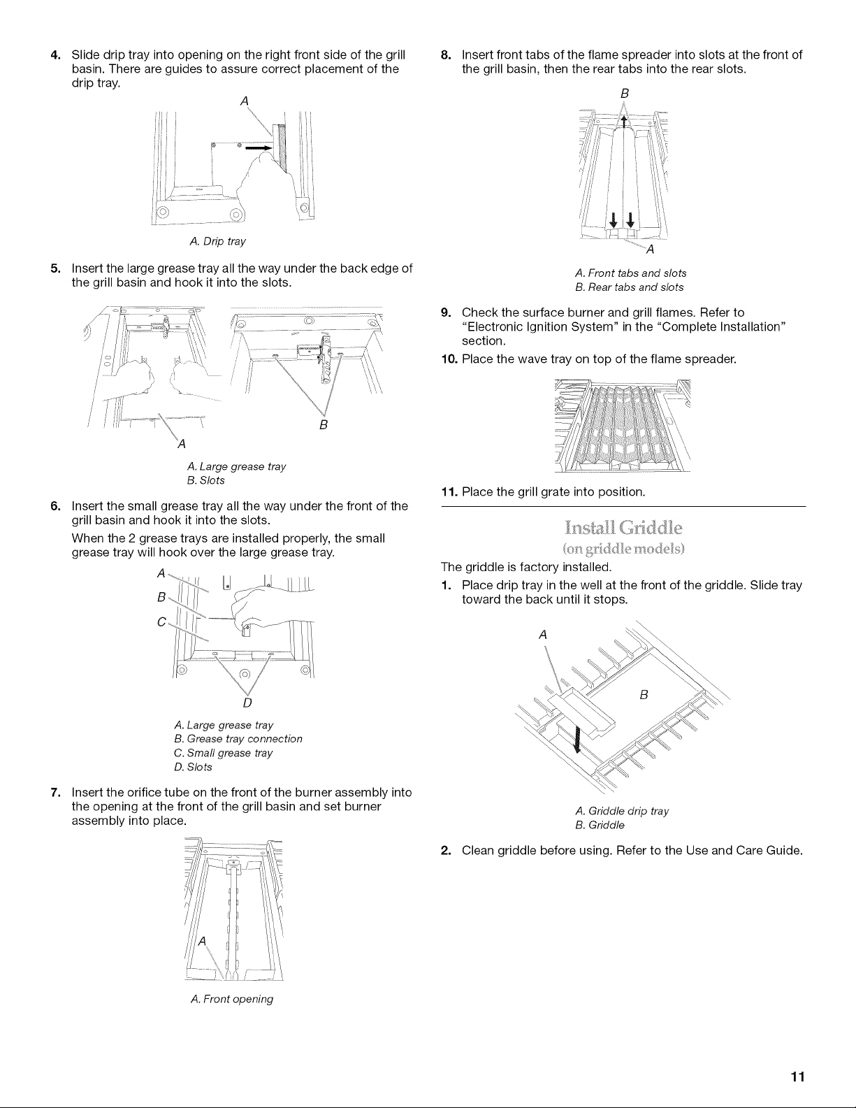
4. 8. Insert front tabs of the flame spreader into slots at the front of
the grill basin, then the rear tabs into the rear slots.
5=
Slide drip tray into opening on the right front side of the grill
basin. There are guides to assure correct placement of the
drip tray.
A
\
ii
iii i
I i i i[i
ii L1
i
, ii_i
J I
A. Drip tray
Insert the large grease tray all the way under the back edge of
the grill basin and hook it into the slots.
B
..........................A
A.Front tabsand slots
B.Reartabs and slots
9. Check the surface burner and grill flames. Refer to
"Electronic Ignition System" in the "Complete Installation"
section.
10. Place the wave tray on top of the flame spreader.
6=
7=
A. Large grease tray
B. Slots
Insert the small grease tray all the way under the front of the
grill basin and hook it into the slots.
When the 2 grease trays are installed properly, the small
grease tray will hook over the large grease tray.
D
A. Large grease tray
B. Grease tray connection
C. Smafl grease tray
D. Slots
Insert the orifice tube on the front of the burner assembly into
the opening at the front of the grill basin and set burner
assembly into place.
11. Place the grill grate into position.
The griddle is factory installed.
1. Place drip tray in the well at the front of the griddle. Slide tray
toward the back until it stops.
A
\
A. Griddle drip tray
B. Griddle
2. Clean griddle before using. Refer to the Use and Care Guide.
A. Front opening
11
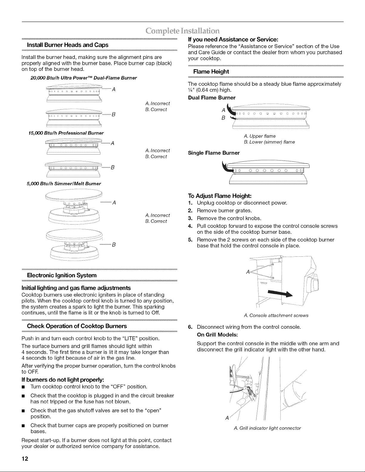
Install Burner Heads and Caps
Install the burner head, making sure the alignment pins are
properly aligned with the burner base. Place burner cap (black)
on top of the burner head.
20,000 Btu/h Ultra Power TM Dual-Flame Burner
z - C -.........
l
15,000 Btu/h Professional Burner
C...... _ /::-?...........A
9 _' 0 0 0 0 0 0 0 =_
A. Incorrect
B. Correct
A. Incorrect
B. Correct
If you need Assistance or Service:
Please reference the "Assistance or Service" section of the Use
and Care Guide or contact the dealer from whom you purchased
your cooktop.
Flame Height
The cooktop flame should be a steady blue flame approximately
1¼.(0.64 cm) high.
Dual Flame Burner
f ........ ,
A
A. Upper flame
B. Lower (simmer) flame
Single Flame Burner
h
5,000 Btu/h Simmer/Melt Burner
B
A. Incorrect
B. Correct
To Adjust Flame Height:
1. Unplug cooktop or disconnect power.
2. Remove burner grates.
3. Remove the control knobs.
4. Pull cooktop forward to expose the control console screws
on the side of the cooktop burner base.
5. Remove the 2 screws on each side of the cooktop burner
base that hold the control console in place.
Electronic Ignition System
Initial lighting and gas flame adjustments
Cooktop burners use electronic igniters in place of standing
pilots. When the cooktop control knob is turned to any position,
the system creates a spark to light the burner. This sparking
continues, until the flame is lit or the knob is turned to Off.
Check Operation of Cooktop Burners
Push in and turn each control knob to the "LITE" position.
The surface burners and grill flames should light within
4 seconds. The first time a burner is lit it may take longer than
4 seconds to light because of air in the gas line.
After verifying the proper burner operation, turn the control knobs
to OFF.
If burners do not light properly:
• Turn cooktop control knob to the "OFF" position.
• Check that the cooktop is plugged in and the circuit breaker
has not tripped or the fuse has not blown.
• Check that the gas shutoff valves are set to the "open"
position.
• Check that burner caps are properly positioned on burner
bases.
Repeat start-up. If a burner does not light at this point, contact
your dealer or authorized service company for assistance.
6=
A. Console attachment screws
Disconnect wiring from the control console.
On Grill Models:
Support the control console in the middle with one arm and
disconnect the grill indicator light with the other hand.
J
A. Grill indicator light connector
12
 Loading...