


KX
Amplifiers
KX 5-CHANNEL AMPLIFIER
KX800.5
Owner’s Manual | English
Manual del Propietario | Español
AMPLIFICADOR DEL LA SERIE KX.5
Benutzerhandbuch | Deutsch
VERSTÄRKER DER KX.5-SERIE
Manuel d’utilisation | Française
AMPLIFICATEUR DE SÉRIE KX.5
2013 KX 5-Channel Amp Rev D.indd 12013 KX 5-Channel Amp Rev D.indd 1 11/8/2012 11:03:31 AM11/8/2012 11:03:31 AM

KX.5-SERIES AMPLIFIERS
OWNER’S MANUAL
MODEL: KX800.5
Authorized KICKER Dealer:
Purchase Date:
Serial Number:
PERFORMANCE
Model: KX800.5
RMS Power, AMP1 and AMP2
@ 14.4V, 4 stereo, 1% THD+N
@ 14.4V, 2 stereo, 1% THD+N
@ 14.4V, 4 mono, 1% THD+N
RMS Power, SUB channel
@ 14.4V, 2 mono, 1.5 % THD+N
@ 14.4V, 4 mono, 1.5 % THD+N
Length | in [cm] 12 3/4 [32.4]
Height | in [cm] 2 1/8 [5.5]
Width | in [cm] 8 5/16 [21]
Frequency Response ± 1dB AMPS 1-2: 10Hz–20kHz
Signal-to-noise Ratio >95dB, A-weighted, re: rated power
Input Sensitivity Low Level: 125mV–5V
Selectable Electronic Crossover AMP 1: OFF/HP/LP, variable 10–5,000Hz with 10X switch;
Bass Boost Variable 0–18dB @ 40Hz
Subsonic Filter Variable 10–80Hz; 24dB/Octave
Remote Bass: Yes [included]
50W x 4
100W x 4
200W x 2
400W x 1
200W x 1
SUB: 10Hz–160Hz
High Level: 250mV–10V
24dB/octave
AMP 2: OFF/HP/LP/BP, variable HP 10–5,00Hz,
variable LP 40–5,000Hz with 10X switch; 24dB/octave
SUB: Variable LP 40–160Hz; 24dB/octave
Pro Tip: To get the best performance from your new KICKER Amplifi er and extend the warranty by 1 year, use
genuine KICKER accessories and wiring.
2
2013 KX 5-Channel Amp Rev D.indd 22013 KX 5-Channel Amp Rev D.indd 2 11/8/2012 11:03:49 AM11/8/2012 11:03:49 AM
INSTALLATION
Mounting: Choose a structurally sound location to mount your KICKER amplifi er. Make sure there are no items
behind the area where the screws will be driven. Choose a location that allows at least 4” (10cm) of open
ventilation for the amplifi er. If possible, mount the amplifi er in the climate-controlled passenger compartment. Drill
four holes using a 7/64” (3mm) bit and use the supplied #8 screws to mount the amplifi er.
Wiring: Disconnect the vehicle’s battery to avoid an electrical short. Then, connect the ground wire to the
amplifi er. Make the ground wire short, 24” (60cm) or less, and connect it to a paint-and-corrosion-free, solid,
metal area of the vehicle’s chassis. Adding an additional ground wire of this same gauge (or larger) between the
battery’s negative post and the vehicle chassis is recommended.
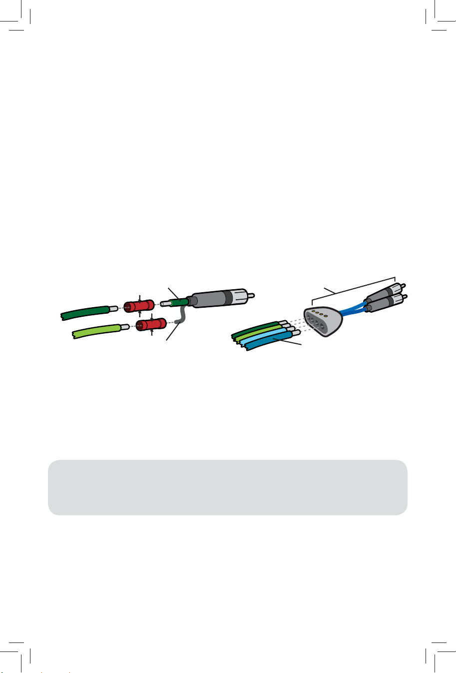
The KX amplifi er has dual input sensitivity differential RCA inputs which will receive either high or low level signals
from your car stereo’s source unit. A high-level signal can be run from the source unit’s speaker outputs to the
stereo RCA input on the end panel of the amplifi er using the KICKER ZISL as shown (make sure you set the KX
amplifi er’s input level switch to “HI”). Alternatively, the signal can be delivered to the amplifi er using the low-level
RCA outputs on the source unit. Set the input level switch on the end panel of the amplifi er to “LO”. Keep the
audio signal cable away from factory wiring harnesses and other power wiring. If you need to cross this wiring,
cross it at a 90 degree angle.
source unit
high-level speaker
outputs
core conductor
+
–
Install a fuse within 18” (45cm) of the battery and in-line with the power cable connected to your amplifi er. If you
ever need to remove the amplifi er from the vehicle after it has been installed, the ground wire should be the last
wire disconnected from the amplifi er--just the opposite as when you installed it.
Model External Fuse
(sold separately)
KX800.5 1 x 100 Ampere 4 Gauge PK4, CK44, ZCK44
shield
to amplifi er
OR
+
–
+
–
Power/Ground Wire KICKER Wiring Kit
KICKER ZISL (optional)
to amplifi er
source unit high-level
speaker outputs
3
2013 KX 5-Channel Amp Rev D.indd 32013 KX 5-Channel Amp Rev D.indd 3 11/8/2012 11:03:49 AM11/8/2012 11:03:49 AM
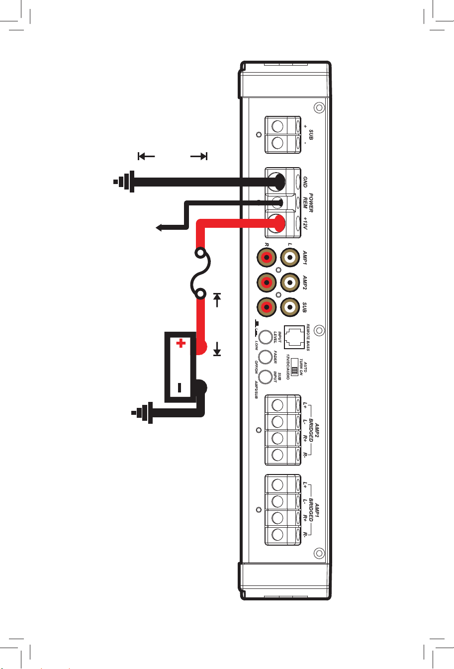
bare-metal
chassis ground
(60cm)
remote turn-on
(see page 6)
battery
24”
external fuse
12V
(45cm)
18”
POWER WIRING
bare-metal
chassis ground
4
2013 KX 5-Channel Amp Rev D.indd 42013 KX 5-Channel Amp Rev D.indd 4 11/8/2012 11:03:49 AM11/8/2012 11:03:49 AM
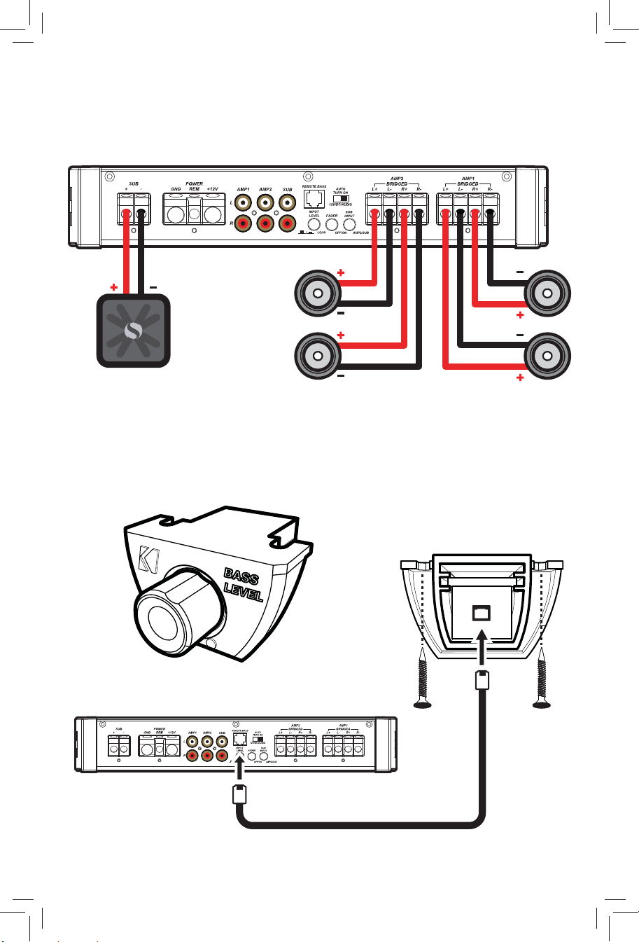
FOUR CHANNEL OPERATION with SUBWOOFER
minimum impedance of 2 ohms per channel (AMP1, AMP2, and SUB channels)
KXRC REMOTE BASS INSTALLATION
See page 6
Surface-mount the KXRC remote
using the supplied screws.
back view
5
2013 KX 5-Channel Amp Rev D.indd 52013 KX 5-Channel Amp Rev D.indd 5 11/8/2012 11:03:49 AM11/8/2012 11:03:49 AM
OPERATION
Automatic Turn-On Selection: The KX series offers three different automatic turn-on modes that can be
selected on the end panel; +12V, DC Offset, and Audio. Using either the DC Offset or Audio mode causes the
REM terminal to have +12V out for turning on additional amplifi ers.
• Remote Turn-On: Set the switch to +12V to use the remote turn-on lead from your source unit. Run 18
gauge wire from the Remote Turn-On Lead on your source unit to the terminal labeled REM between the
amplifi er’s positive and negative power terminals. This is the preferred automatic turn-on method.
• DC Offset Turn-On: If Remote Turn-On is not an option, the next best setting is DC Offset. The DC Offset
mode detects a 6V DC offset from the HI-Level speaker outputs when the source unit has been turned on.
• Signal Sense Turn-On: The Audio setting is the fi nal alternative for Automatic turn-on. This is a Signal Sense
turn-on method that detects the incoming audio signal from your source unit and automatically turns on the
amp. This turn-on method will not work properly if the input gain control is not set appropriately.
Input Level: The RCA inputs on KICKER KX amplifi ers are capable of receiving either Hi or Low-level signals
from your source unit. If the only output available from your source unit is a Hi-Level signal, simply press in the
Input Level switch on the amplifi er. Refer to the wiring section of this manual for additional instructions.
Fader Switch: Depress the fader switch if you are running two sets of inputs (front and rear for example) to the
amplifi er. Leave the fader switch OFF if you want to drive all channels from a single stereo input.
Sub Input: If there is no dedicated output on your source unit for a subwoofer, use the SUB INPUT switch to set
your subwoofer input to either SUB INPUT or AMP INPUT 2.
Input Gain Control: The input gain control is not a volume control. It matches the output of the source unit to
the input level of the amplifi er. Turn the source unit up to about 3/4 volume (if the source unit goes to 30, turn it
to 25). Next, slowly turn (clockwise) the gain on the amplifi er up until you can hear audible distortion, then turn it
down a little.
KICK EQ Bass Boost Control: The variable bass boost control on the side of the amplifi er is designed to
give you increased output, 0–18dB, at 40 Hz. The setting for this control is subjective. If you turn it up, you must
readjust the input gain control to avoid clipping the amplifi er.
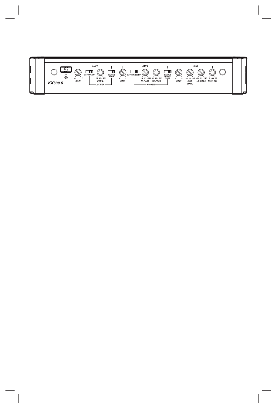
Crossover Switches with Frequency Multiplier: Use the XOVER switches on the end panel of the amplifi er
to set the internal crossovers of AMPS 1 & 2 to OFF, HI-PASS, LO-PASS, or BAND-PASS (AMP 2 only). When
the switch is set to OFF, a full bandwidth signal will be amplifi ed. Set the switch to HP if you want the amplifi er’s
internal crossover to serve as a high-pass fi lter. Set the switch to LP if you want the amplifi er’s internal crossover
to serve as a low-pass fi lter. Set the switch to BP when a specifi c frequency range is required. Never change the
crossover switches with the audio system on!
Set the 1X/10X frequency multiplier switch to the setting that is appropriate for your application. A setting of
10X will set the range of the AMP 1 crossover to 100–5,000Hz, and the LO-PASS crossover of AMP 2 to
400–5,000Hz.
6
2013 KX 5-Channel Amp Rev D.indd 62013 KX 5-Channel Amp Rev D.indd 6 11/8/2012 11:03:50 AM11/8/2012 11:03:50 AM

Adjustable Subsonic Filter (SUB): The variable subsonic fi lter will provide a cut-off point for lower frequencies
(10–80Hz) that could potentially damage your speakers from over-excursion, along with wasting your amplifi er’s
power. The setting for this control should be set relative to your speaker’s low-frequency capability.
Remote Bass-KXRC: With the KXRC remote bass level control, you have the ability to control the output level
of the amplifi er remotely. To surface-mount the KXRC remote bass level control, simply screw the remote to the
chosen location, then run the cable from the controller to the “Remote Bass” jack on the amplifi er panel. Do NOT
connect/disconnect while the amplifi er is on. See page 5.
TROUBLESHOOTING
If your amplifi er does not appear to be working, check the obvious things fi rst such as blown fuses, poor or
incorrect wiring connections, incorrect setting of crossover switch and gain controls, etc. There is a Protection
(PRT) LED on the side panel of your KICKER KX series amplifi er. Depending on the state of the amplifi er and the
vehicle’s charging system, the LED will either glow red or be off.
Red (PRT) LED fl ickering with loud music? The red (PRT) LED indicates low battery voltage or an illegal
load. Check all the connections in your vehicle’s charging system. It may be necessary to replace or charge your
vehicle’s battery or replace your vehicle’s alternator.
Red (PRT) LED on, no output? Amplifi er is very hot = thermal protection is engaged. Test for proper
impedance at the speaker terminals with a VOM meter (see the diagrams in this manual for minimum
recommended impedance and multiple speaker wiring suggestions). Also check for adequate airfl ow around
the amplifi er. Amplifi er shuts down only while vehicle is running = voltage protection circuitry is engaged.
Voltage to the amplifi er is not within the 10–16 volt operating range. Have the vehicle’s charging and electrical
system inspected. Amplifi er will only play at low volume levels = short circuit protection is engaged. Check
for speaker wires shorted to each other or to the vehicle chassis. Check for damaged speakers or speaker(s)
operating below the minimum recommended impedance.
No or low output? Check the balance control on source unit Check the RCA (or speaker input) and
speaker output connections.
Alternator noise-whining sound with engine’s RPM? Check for damaged RCA (or speaker input) cable
Check the routing of RCA (or speaker input) cable Check the source unit for proper grounding Check
the gain settings and turn them down if they are set too high.
Reduced bass response? Reverse a speaker connection from positive to negative on the stereo/subwoofer
channel(s); if the bass improves, the speaker was out of phase.
Ground Noise? KICKER amplifi ers are engineered to be fully compatible with all manufacturers’ head units.
Some head units may require additional grounding to prevent noise from entering the audio signal. If you are
experiencing this problem with your head unit, in most cases running a ground wire from the RCA outputs on the
head unit to the chassis will remedy this issue.
CAUTION: When jump starting the vehicle, be sure that connections made with jumper cables are correct.
Improper connections can result in blown amplifi er fuses as well as the failure of other critical systems in the
vehicle.
If you have more questions about the installation or operation of your new KICKER product, see the Authorized
KICKER Dealer where you made your purchase. For more advice on installation, click on the SUPPORT tab on
the KICKER homepage, www.kicker.com. Choose the TECHNICAL SUPPORT tab, choose the subject you are
interested in, and then download or view the corresponding information. Please E-mail support@kicker.com or
call Technical Services (405) 624-8583 for unanswered or specifi c questions.
7
2013 KX 5-Channel Amp Rev D.indd 72013 KX 5-Channel Amp Rev D.indd 7 11/8/2012 11:03:50 AM11/8/2012 11:03:50 AM

KICKER will now provide a threeyear warranty with all KX-Series
Amplifi er purchases paired with a
qualifying KICKER Installation Kit* .
This extends the standard warranty by an additional
year. Amplifi er and Kit must be purchased from an
Authorized KICKER Dealer.
KICKER KX amplifi er success is currently at an unheard-of rate, making the extended
warranty program even more benefi cial to you.
Using poor-quality, under-spec wiring kits will impede KX amplifi er performance.
A superior-quality KICKER installation Kit is guaranteed to extend the life of KX
amplifi ers.
The new extended warranty applies only to KICKER amplifi ers and accessories sold to consumers by Authorized
KICKER Dealers in the United States of America or its possessions. It also only applies to the original purchaser of
KICKER amplifi ers and accessories. One warranty extension per amplifi er is allowed regardless of the number of amplifi er
installation kits purchased. This program does not apply to “B”-stock product or factory-refurbished product.
This offer is for a limited time, so see your local Authorized KICKER Dealer soon for details.
*U.S.A. Only | EE.UU. solamente | Nur USA | Les USA Seulement
KX800.5
50W x 4 @ 4 ohms (10Hz–20,000Hz)
Signal to Noise Ratio -75dB CEA-2006B (ref: 1W, A-weighted)
200W x 1 @ 4 ohms (40Hz–160Hz)
Signal to Noise Ratio -75dB CEA-2006B (ref: 1W, A-weighted)
14.4VDC, 1% THD, CEA-2006B (Watts)
8
2013 KX 5-Channel Amp Rev D.indd 82013 KX 5-Channel Amp Rev D.indd 8 11/8/2012 11:03:51 AM11/8/2012 11:03:51 AM

AMPLIFICADOR DE LA SERIE KX.5
MANUAL DEL PROPIETARIO
MODELO: KX800.5
Distribuidor autorizado de KICKER:
Fecha de compra:
Número de serie del amplifi cador:
RENDIMIENTO
Modelo: KX800.5
Alimentación RMS, AMP1 y AMP2
@ 14.4V, 4 estéreo, 1% THD+N
@ 14.4V, 2 estéreo, 1% THD+N
@ 14.4V, 4 mono, 1% THD+N
Alimentación, SUB canal
@ 14.4V, 2Ω monofónico, 1.5% THD+N
@ 14.4V, 4Ω monofónico, 1.5% THD+N
Longitud | pulg. [cm] 12 3/4 [32.4]
Altura | pulg. [cm] 2 1/8 [5.5]
Ancho | in [cm] 8 5/16 [21]
Respuesta de frecuencia ± 1dB AMPS 1-2: 10Hz–20kHz
Relación señala a ruido >95dB, ponderado-A, re: potencia nominal
Sensibilidad de entrada Bajo Nivel: 125mV–5V
Separador de frecuencia electrónico AMP 1: OFF/HP/LP, variable 10–5,000Hz con un
Amplifi cación de bajos Variable 0–18dB @ 40Hz
Filtro subsónico
Bajo remoto:
50W x 4
100W x 4
200W x 2
400 x 1
200 x 1
SUB: 10Hz–160Hz
Alto Nivel: 250mV–10V
interruptor 10X ; 24dB/octava
AMP 2: OFF/HP/LP/BP, variable HP 10–5,00Hz,
variable LP 40–5,000Hz con un interruptor 10X; 24dB/
octava
SUB: Variable LP 40–160Hz; 24dB/octava
Variable 10–80Hz; 24dB/Octava
Si[incluido]
Nota: Para obtener el mejor rendimiento de sus nuevos amplifi cadores KICKER, le recomendamos que use
accesorios y cableado KICKER auténticos.
9
2013 KX 5-Channel Amp Rev D.indd 92013 KX 5-Channel Amp Rev D.indd 9 11/8/2012 11:03:51 AM11/8/2012 11:03:51 AM

INSTALACIÓN
Montaje: Escoja un lugar estructuralmente sólido para montar el amplifi cador KICKER. Asegúrese de que no
haya nada por detrás de dónde van a entrar los tornillos. Escoja un lugar en que queden por lo menos 4 plg.
(10 cm) de espacio abierto de ventilación alrededor del amplifi cador. Si es posible, monte el amplifi cador en el
compartimiento de pasajeros, con ambiente acondicionado. Haga cuatro agujeros con una broca de 7/64 de
plg. (3 mm) y monte el amplifi cador con los tornillos N° 8 que se suministran.
Cableado: Desconecte la batería del vehículo para evitar cortocircuitos. Luego, conecte un cable de conexión
a tierra al amplifi cador. El cable de conexión a tierra debe ser corto, de 24 plg. (60 cm) o menos, y debe
ir conectado a un punto sólido del chasis del vehículo en que no haya ni pintura ni corrosión. También se
recomienda instalar un cable de conexión a tierra adicional, de este mismo calibre (o de mayor calibre), entre la
terminal negativa de la batería y el chasis del auto.
El amplifi cador KX tiene entradas RCA diferenciales de doble sensibilidad de entrada que reciben señales de
alto nivel o bajo nivel de la unidad fuente del sistema estereofónico del automóvil.La señal se puede llevar al
amplifi cador desde las salidas de altavoz de alto nivel de la unidad fuente. Fije el selector de nivel de entrada del
panel de extremo del amplifi cador en la posición de alto (HI). Engarce y suelde conectores RCA al extremo del
cable de altavoz procedente de las salidas de altavoz de alto nivel de la unidad fuente y conéctelo a las entradas
RCA del panel de extremo del amplifi cador o simplifi car la instalación mediante un ZISL KICKER como se
muestra a continuación. Como alternativa, puede conectar producción de su unidad fuente a las entradas RCA
del amplifi cador KX RCA. Fije el selector de nivel de entrada del panel de extremo del amplifi cador en la posición
de bajo (LO). Mantenga el cable de señal de audio alejado de los arneses de cableado de fábrica y otros cables
de alimentación. Si es necesario cruzar este cableado, crúcelo en un ángulo de 90°.
Cable de salida
de altavoz de
alto nivel
cable central
+
–
Conexión a tierra o blindaje
Instale un fusible a menos de 18 plg. (45 cm) de la batería y en línea con el cable de alimentación conectado al
amplifi cador. Si alguna vez necesita desmontar el amplifi cador, el cable de conexión a tierra debe ser el último
que se desconecte del amplifi cador. Exactamente lo contrario de lo que se hace cuando se instala.
Modelo Fusible
Externo
(no incluido)
KX800.5 1 x 100A Calibre 4 PK4, CK44, ZCK44
Cable de Alimentación y
Conexión a Tierra
Hacia el amplifi cador
O
+
–
+
–
KICKER ZISL
Hacia el
amplifi cador
Cable de salida de
altavoz de alto nivel
Kit de cableado
KICKER
10
2013 KX 5-Channel Amp Rev D.indd 102013 KX 5-Channel Amp Rev D.indd 10 11/8/2012 11:03:51 AM11/8/2012 11:03:51 AM

18”
(45cm)
12V
batería
fusible externo
encendido a distancia
conexión a tierra
(página 13)
24”
(60cm)
conexión a tierra
11
2013 KX 5-Channel Amp Rev D.indd 112013 KX 5-Channel Amp Rev D.indd 11 11/8/2012 11:03:52 AM11/8/2012 11:03:52 AM

FUNCIONAMIENTO POR CUATRO CANALES CON SUBWOOFER
impedancia mínima de 2 ohmios por canales (AMP1, AMP2, y SUB canales)
KXRC CONTROL REMOTO DE BAJOS INSTALACIÓN
(no incluido KXRC. Vea la página 13)
Para instalar en superfi cie el control remoto
KXRC use los tornillos suministrados.
vista desde atrás
12
2013 KX 5-Channel Amp Rev D.indd 122013 KX 5-Channel Amp Rev D.indd 12 11/8/2012 11:03:52 AM11/8/2012 11:03:52 AM

FUNCIONAMIENTO
Selección de encendido automático: Las series KX ofrecen tres diferentes modos de encendido que se
pueden seleccionar en el panel fi nal; +12V, compensación de la CC, y Audio. Utilizando ya sea la compensación
de la CC o el modo de audio, provoca que la terminal REM +12V de salida para encender los amplifi cadores
adicionales.
• Encendido remoto: Establezca el interruptor a +12V para utilizar el encendido remoto para usar la terminal
de encendido remoto de su unidad fuente. Corra el alambre calibre 18 desde la terminal de encendido del
remoto en su unidad fuente a la terminal etiquetada REM entre las terminales de energía positiva y negativa
del amplifi cador. Este es el método preferido de encendido.
• Encendido desde la compensación de CC: Si el encendido remoto no es una opción, el siguiente mejor
ajuste en la compensación de CC. La el modo de compensación CC detecta una compensación de CC
cuando la unidad fuente se ha encendido.
• Sensor de señal de encendido: El ajuste de audio es la alternativa fi nal para un encendido automático.
Este es el método de encendido del sensor de señal que detecta la señal de audio entrante desde su
unidad fuente, y que enciende automáticamente el amplifi cador. Este método de encendido no funcionará
apropiadamente si el control de ganancia de entrada no se confi gura adecuadamente.
Nivel de entrada: Las entradas RCA sobre los amplifi cadoras KICKER KX son capaces de recibir señales ya
sean de nivel alto o bajo desde su unidad fuente. Si la única salida disponible de su unidad fuente es una señal
de alto nivel, simplemente presione el interruptor de entrada sobre el amplifi cador. Refi érase a la sección de
cableado de este manual para instrucciones adicionales.
Interruptor del atenuador: Deprima el interruptor del atenuador si está operando dos juegos de entrada
(delantero y trasero por ejemplo) al amplifi cador. Deje el interruptor del atenuador apagado si desea manejar
todos los canales desde una única entrada estéreo.
Sub entrada: Si no existe una salida dedicada en su unidad fuente para un subwoofer, utilice el interruptor de
SUB ENTRADA para ajustar la entrada de su subwoofer ya sea a la SUB ENTRADA o a la ENTRADA AMP 2.
Control de ganancia de entrada: El control de ganancia de entrada no es un control de volumen.
Concuerda con la salida de la unidad fuente al nivel de entrada del amplifi cador. Gire la unidad fuente hasta
aproximadamente 3/4 de volumen (si la unidad fuente va hasta 30, gírela hasta 25). Luego, gire lentamente
(hacia la derecha) arriba la ganancia sobre el amplifi cador hasta que pueda escuchar una distorsión audible,
luego gírela un poco hacia abajo.
Control de impulso del bajo: El control variable de intensifi cación de bajos en el lado del amplifi cador está
diseñado para brindarle una salida incrementada, 0–18dB,
desea girarlo hacia arriba, debe reajustar el control de ganancia de entrada para evitar recortar el amplifi cador.
Interruptores de transición con multiplicador de frecuencia: Use los interruptores XOVER en el panel
fi nal del amplifi cador para ajustar las transiciones internas de AMPS 1 y 2 a APAGADO, PASO ALTO, PASO
BAJO, o PASO DE BANDA (únicamente AMP 2). Cuando el interruptor se ajusta a APAGADO, se amplifi cará
una señal completa de banda ancha. Ajuste el interruptor a HP si desea que la transición interna del amplifi cador
sirva como un fi ltro de paso alto. Ajuste el interruptor a LP si desea que la transición interna del amplifi cador sirva
como un fi ltro de paso bajo. Ajuste este interruptor a BP cuando requiera un rango de frecuencia específi co.
¡Nunca cambie los interruptores de transición cuando esté encendido el sistema de audio!
Ajuste el interruptor del multiplicador de frecuencia 1X/10X a la selección que sea apropiada para su aplicación.
Un ajuste de 10X seleccionará el rango de transición de AMP 1 a 100–5,000Hz, y la transición de LO-PASS del
AMP 2 a 400–5,000Hz.
a 40 Hz. El ajuste para este control es subjetivo. Si
13
2013 KX 5-Channel Amp Rev D.indd 132013 KX 5-Channel Amp Rev D.indd 13 11/8/2012 11:03:53 AM11/8/2012 11:03:53 AM

Filtro subsónico ajustable (SUB): El fi ltro subsónico variable proporcionará un punto de corte para
frecuencias bajas (10–80Hz) que podría dañar potencialmente sus bocinas por sobre excursión, además de
desperdiciar la potencia de su amplifi cador. El ajuste para este control se debe de ajustar en relación con la
capacidad de frecuencia baja de su bocina.
Bajo remoto-KXRC: Con el control de nivel bajo de KXRC, tiene la capacidad de controlar remotamente el
nivel de salida de su amplifi cador. Par montar en la superfi cie el control de nivel de bajos KXRC, simplemente
atornille el remonto a la ubicación elegida, luego corra el cable desde el controlador hasta la clavija del “Bajo
remoto” en el panel del amplifi cador. NO conecte/desconecte mientras que esté encendido el amplifi cador. Vea
la página 12.
RESOLUCIÓN DE PROBLEMAS
Si su amplifi cador parece no estar funcionando, revise lo obvio primero: fusibles quemados, conexiones malas o
incorrectas, posición incorrecta de los selectores de crossover y amplifi cación, etc. Su amplifi cador modelo KX
de KICKER cuenta con un LED de protección (PRT) en el panel de alimentación lateral. Dependiendo del estado
del amplifi cador y del sistema de carga del vehículo, los LED se iluminarán en rojo o ser apagar.
¿El indicador luminoso LED de “protection” destella con la música fuerte? El indicador luminoso LED
rojo indica que hay bajo voltaje de batería o una carga ilegal. Revise todas las conexiones del sistema de carga
eléctrica del vehículo. Puede ser necesario cambiar o cargar la batería del vehículo o cambiar el alternador del
vehículo.
¿El indicador luminoso LED de “protection” está encendido y no hay salida? El amplifi cador está
muy caliente = Se ha activado el circuito de protección térmica. Con un medidor VOM, compruebe que las
terminales de altavoz tengan la impedancia correcta (vea en este manual los diagramas que contienen datos de
impedancia mínima recomendada y sugerencias de cableado de varios altavoces). Asegúrese también de que
haya un fl ujo de aire adecuado alrededor del amplifi cador. El amplifi cador se apaga sólo cuando el vehículo
está en marcha = Se ha activado el circuito de protección contra sobrevoltaje. El voltaje al amplifi cador no está
dentro del intervalo de funcionamiento de 10V a 16V. Haga inspeccionar el sistema eléctrico y de carga eléctrica
del automóvil. El amplifi cador sólo funciona a bajo volumen = Se ha activado el circuito de protección contra
cortocircuitos. Asegúrese de que los cables de los altavoces no estén en cortocircuito entre sí o con el chasis
del vehículo. Vea si hay altavoces dañados o funcionando a menos de la impedancia mínima recomendada.
¿No hay salida de uno de los canales? Revise el control de balance de la unidad fuente. Revise las
conexiones RCA (o de entrada de altavoz) y de salida de altavoz del canal.
¿Hay ruido sibilante de alternador asociado a las RPM del motor? Vea si hay algún cable RCA (o de
entrada de altavoz) dañado. Revise el encaminamiento del cable RCA (o de entrada de altavoz). Vea si la
unidad fuente tiene conexión a tierra apropiada. Revise las confi guraciones de amplifi cación y bájelas si están
muy altas.
¿Hay baja respuesta de bajos? Invierta la conexión de uno de los altavoces de positiva a negativa en los
canales estereofónicos y/o de subwoofer; si los bajos mejoran, el altavoz estaba fuera de fase.
¿Hay ruido de conexión a tierra? Los amplifi cadores KICKER son totalmente compatibles con las unidades
fuente de todos los fabricantes. Algunas unidades principales pueden necesitar más conexión a tierra para
evitar que entre ruido a la señal de audio. En la mayoría de los casos, este problema con la unidad principal se
resuelve instalando un cable de conexión a tierra desde las salidas RCA de la unidad principal al chasis.
14
2013 KX 5-Channel Amp Rev D.indd 142013 KX 5-Channel Amp Rev D.indd 14 11/8/2012 11:03:53 AM11/8/2012 11:03:53 AM

PRECAUCIÓN: Cuando haga arrancar el vehículo con cables de arranque conectados a una batería externa,
asegúrese de que las conexiones de los cables de arranque sean correctas. Conectar los cables de arranque
de manera incorrecta puede quemar los fusibles del amplifi cador y causar fallas en otros sistemas del vehículo.
Si tiene más preguntas sobre la instalación de su nuevo producto KICKER, vaya al distribuidor autorizado de
KICKER donde lo compró. Si necesita más consejos sobre la instalación, haga clic en la lengüeta SUPPORT
(apoyo) de la página Web de KICKER, www.kicker.com. Escoja la lengüeta TECHNICAL SUPPORT (apoyo
técnico), escoja el tema que le interese y luego descargue o vea la información correspondiente. Envíe un
mensaje por correo electrónico a support@kicker.com o comuníquese con Servicios Técnicos llamando al (405)
624-8583 si tiene preguntas específi cas o a las cuales no haya encontrado respuesta.
KX800.5
50W x 4 @ 4 ohmios (20Hz–20,000Hz)
Relación de Señal a Ruido -75dB CEA-2006B (ref: 1W, ponderado en A)
200 x 1 @ 4 ohmios (25Hz–200Hz)
Relación de Señal a Ruido -75dB CEA-2006B (ref: 1W, ponderado en A)
14.4VCC, 1% THD, CEA-2006B (W)
15
2013 KX 5-Channel Amp Rev D.indd 152013 KX 5-Channel Amp Rev D.indd 15 11/8/2012 11:03:53 AM11/8/2012 11:03:53 AM

VERSTÄRKER DER KX.5 SERIE
BENUTZERHANDBUCH
MODELL: KX800.5
Autorisierter KICKER-Händler:
Kaufdatum:
Verstärker-Seriennummer:
LEISTUNG
Modell: KX800.5
RMS-Leistung, AMP1 und AMP2
@ 14.4V, 4Ω stereo, 1% Gesamtklirrfaktor
@ 14.4V, 2Ω stereo, 1% Gesamtklirrfaktor
@ 14.4V, 4Ω mono, 1% Gesamtklirrfaktor
RMS-Leistung, SUB kanal
@ 14.4V, 2Ω mono, 1,5% Gesamtklirrfaktor
@ 14.4V, 4Ω mono, 1,5% Gesamtklirrfaktor
Länge | Zoll [cm] 12 3/4 [32.4]
Höhe | Zoll [cm] 2 1/8 [5.5]
Breite | Zoll [cm] 8 5/16 [21]
Frequenzgang ± 1dB AMPS 1 - 2: 10Hz–20kHz
Rauschabstand >95 dB, A-bewertet: Nennleistung
Eingangsempfi ndlichkeit N-Pegel: 125mV–5V
Einstellbare elektronische Frequenzweiche AMP 1: OFF/HP/TP, variabel 10 – 5.000 Hz mit
KICKEQ Bass-Boost Variabel 0 – 18 dB @ 40 Hz
Trittschallfi lter Variabel 10 – 80 Hz; 24 dB/Oktave
Bassfernregelung: Ja [enthalten]
50W x 4
100W x 4
200W x 2
400 x 1
200 x 1
SUB: 10Hz–160Hz
H-Pegel: 250mV–10V
10-fach-Schalter; 24 dB/Oktave
AMP 2: OFF/HP/TP/BP, variabel HP 10 – 500 Hz,
variabler TP 40 – 5.000 Hz mit 10-fach-Schalter; 24
dB/Oktave
SUB: Variabler TP 40 – 160 Hz; 24 dB/Oktave
Hinweis: Um das Maximum aus Ihrem neuen KICKER-Verstärker herauszuholen, sollten Sie echtes KICKER-
Zubehör und KICKER-Kabel verwenden.
INSTALLATION
Befestigung: Wählen Sie für die Installation des KICKER-Verstärkers eine strukturell stabile Stelle. Vergewissern
Sie sich, dass sich hinter der Einschraubposition der Schrauben nichts befi ndet. Wählen Sie eine Stelle, die
mindestens 10 cm Lüftungsfreiraum für den Verstärker bietet. Installieren Sie, wenn möglich, den Verstärker im
klimatisierten Fahrgastraum. Bohren Sie mit einem 3-mm-Bohrer vier Löcher und verwenden Sie die beiliegenden
Nr. 8-Schrauben zur Befestigung des Verstärkers.
16
2013 KX 5-Channel Amp Rev D.indd 162013 KX 5-Channel Amp Rev D.indd 16 11/8/2012 11:03:53 AM11/8/2012 11:03:53 AM

Anschluss: Trennen Sie den Anschluss der Fahrzeugbatterie, um einen Kurzschluss zu vermeiden. Schließen
Sie dann das Massekabel an den Verstärker an. Verwenden Sie ein kurzes Erdungskabel (maximal 60 cm) und
schließen Sie es an eine lack- oder korrosionsfreie Metallstelle an der Fahrzeugkarosserie an. Es wird auch
empfohlen, ein weiteres Massekabel mit gleicher (oder größerer) Drahtstärke zwischen dem negativen Pol der
Autobatterie und der Fahrzeugkarosserie zu verwenden.
Der KX-Verstärker hat zwei RCA-Eingänge mit Eingangsempfi ndlichkeits-Differential, die entweder Hoch- oder
Niedrigpegelsignale vom Autoradio empfangen. Kann das Signal mit den Hochpegel-Lautsprecherausgängen
am Autoradio an den Verstärker übertragen werden. Stellen Sie den Eingangspegelschalter an der Endplatte
des Verstärkers auf „HI“. Crimpen und löten Sie die RCA-Stecker an das Ende des Lautsprecherkabels von den
Hochpegel-Lautsprecherausgängen am Autoradio und verbinden Sie das Kabel mit den RCA-Eingängen an der
Endplatte des Verstärkers, oder Vereinfachung der Installation, indem Sie ein KICKER ZISL wie unten gezeigt.
Alternativ können Sie Ihre Quelle Einheit Cinch-Ausgänge zum KX Verstärker Cinch-Eingänge anschließen. Stellen
Sie den Eingangspegelschalter an der Endplatte des Verstärkers auf „LO“. Achten Sie beim Verlegen dieser
Audiokabel darauf, dass sie Werks-Kabelbäume und andere Stromkabel nicht berühren. Wenn Sie die Kabel
überkreuzen müssen, tun Sie dies in einem 90-Grad-Winkel.
HochpegelLautsprecherausgangskabel
+
–
Installieren Sie in maximal 45 cm Entfernung von der Batterie eine Sicherung in Reihe mit dem Stromkabel zum
Verstärker. Wenn Sie je den Verstärker nach der Installation aus dem Fahrzeug ausbauen müssen, sollte die
Masseleitung als letzte vom Verstärker getrennt werden, genau in der umgekehrten Reihenfolge wie bei der
Installation.
Modell Externe Sicherung
(nicht inbegriffen)
KX800.5 1 x 100 Ampere 4 GA PK4, CK44, ZCK44
Kabelseele
Erdung oder Abschirmung
Zum Verstärker
ODER
+
–
+
–
Massekabel KICKER Verkabelungssatz
KICKER ZISL
Zum Verstärker
HochpegelLautsprecherausgangskabel
17
2013 KX 5-Channel Amp Rev D.indd 172013 KX 5-Channel Amp Rev D.indd 17 11/8/2012 11:03:54 AM11/8/2012 11:03:54 AM

Masse
(Seite 20)
Masse
(60cm)
24”
Ferneinschaltung
externe Sicherung
Batterie
12V
(45cm)
18”
18
2013 KX 5-Channel Amp Rev D.indd 182013 KX 5-Channel Amp Rev D.indd 18 11/8/2012 11:03:54 AM11/8/2012 11:03:54 AM

VIERKANALBETRIEB MIT SUBWOOFER
Minimal impedanz von 2 Ohm pro Kanal (AMP1, AMP2, und SUB Kanäle)
KXRC BASSPEGEL-FERNBEDIENUNG INSTALLATION
(KXRC nicht inbegriffen. Siehe Seite 20.)
Montieren Sie den KXRC-Remote-Regler mit den
mitgelieferten Schrauben.
Rückansicht
19
2013 KX 5-Channel Amp Rev D.indd 192013 KX 5-Channel Amp Rev D.indd 19 11/8/2012 11:03:55 AM11/8/2012 11:03:55 AM

BETRIEB
Wahlschalter Automatische Einschaltung: Die KX-Serie bietet drei verschiedene Varianten für automatische
Einschaltung, die sich am Anschlusspanel einstellen lassen: +12 V, DC-Offset und Audio. Bei der Verwendung
von DC-Offset- oder Audio-Modus hat das REM-Terminal einen Ausgang von +12 V, um weitere Verstärker
anzuschalten.
• Ferneinschaltung: Stellen Sie den Regler auf +12V, um die Ferneinschaltungsleitung Ihres Quellgerätes
zu verwenden. Legen Sie ein 18-AWG-Kabel von der Ferneinschaltungs-Zuleitung Ihres Quellgeräts zur
Klemme mit der Beschriftung „REM“, die sich zwischen den positiven und negativen Stromklemmen des
Verstärkers befi ndet. Dies ist die bevorzugte Methode zur automatischen Einschaltung.
• DC-Offset-Einschaltung: Falls eine Ferneinschaltung nicht in Frage kommt, ist die zweitbeste Einstellung
DC-Offset. Der DC-Offset-Modus erkennt einen Offset von 6 V DC an den Hochtönerausgängen, nachdem
das Quellgerät eingeschaltet wurde.
• Signalerkennungs-Einschaltung: Die letzte Alternative für automatische Einschaltung ist die AudioEinstellung. Das ist eine Signalerkennungsmethode, die das eingehende Audiosignal vom Quellgerät
erkennt und den Verstärker automatisch einschaltet. Diese Einschaltmethode funktioniert nur dann
ordnungsgemäß, wenn die Eingangslautstärkeregelung entsprechend eingestellt ist.
Eingangspegel: Die RCA-Eingänge von KICKER KX-Verstärkern können Eingangssignale mit hohem oder
niedrigem Pegel von Ihrem Quellgerät empfangen. Falls von Ihrem Quellgerät nur ein Signal mit hohem Pegel zur
Verfügung steht, drücken Sie einfach den „Input Level“-Schalter am Verstärker. Weitere Anweisungen fi nden Sie
im Abschnitt “Verkabelung” in dieser Anleitung.
Fader-Schalter: Drücken Sie den Fader-Schalter, falls Sie zwei Eingangssätze am Verstärker betreiben wollen
(zum Beispiel vorne und hinten). Lassen Sie den Fader-Schalter auf OFF, wenn Sie alle Kanäle von einem
einzigen Stereosignal aus betreiben wollen.
Sub Input: Falls Ihr Quellgerät keinen ausgewiesenen Subwoofer-Ausgang hat, verwenden Sie den „SUB
INPUT“-Schalter, um Ihren Subwoofer-Eingang entweder auf SUB INPUT oder AMP INPUT 2 zu setzen.
Eingangspegelregler: Der Eingangspegelregler ist keine Lautstärkeregelung. Er passt das Ausgangssignal
des Quellgerätes dem Eingangspegel des Verstärkers an. Drehen Sie das Quellgerät auf etwa 3/4 der
Lautstärke (geht das Quellgerät bis 30, drehen Sie es auf 25). Dann drehen Sie langsam (im Uhrzeigersinn) den
Eingangspegel des Verstärkers hoch, bis Sie eine wahrnehmbare Verzerrung hören. Anschließend drehen Sie ihn
wieder ein bisschen herunter.
KICK EQ Bass-Boost-Regler: Der Bass-Boost-Regler seitlich am Verstärker ermöglicht ein Ausgangssignal,
das in der gewählten Frequenz (0 bis 18 dB) bei 40 Hz. Die Einstellung für diesen Regler ist Geschmackssache.
Wenn Sie diesen Wert erhöhen, sollten Sie den Eingangspegel anpassen, um ein Clipping des Verstärkers zu
vermeiden.
20
2013 KX 5-Channel Amp Rev D.indd 202013 KX 5-Channel Amp Rev D.indd 20 11/8/2012 11:03:56 AM11/8/2012 11:03:56 AM

Frequenzweichenschalter mit Frequenzvervielfacher: Mit dem XOVER-Schalter am Anschlusspanel
des Verstärkers kann die interne Frequenzweiche der AMPS 1 und 2 auf OFF, HI-PASS (Hochpass), LO-PASS
(Tiefpass) oder BAND-PASS (Bandpass)(nur AMP 2) gestellt werden. Steht der Schalter auf OFF, wird ein
Signal in voller Bandbreite verstärkt. Stellen Sie den Schalter auf HP, wenn Sie die interne Frequenzweiche
des Verstärkers als Hochpassfi lter verwenden wollen. Stellen Sie den Schalter auf LP, wenn Sie die interne
Frequenzweiche des Verstärkers als Tiefpassfi lter verwenden wollen. Stellen Sie den Regler auf BP, wenn ein
bestimmter Frequenzbereich benötigt wird. Betätigen Sie den Frequenzweichenschalter ausschließlich bei
ausgeschaltetem Audiosystem!
Stellen Sie den 1X/10X(1- bis 10-fach)-Frequenzvervielfacher-Schalter auf die Einstellung, die Ihrer Anwendung
am besten entspricht. Eine Einstellung von 10X setzt den Frequenzweichen-Bereich bei AMP 1 auf 100 – 5.000
Hz und die Tiefpass-Frequenzweiche von AMP 2 auf 400 – 5.000 Hz.
Einstellbares Trittschallfi lter (SUB): Das einstellbare Trittschallfi lter regelt den Schwellenwert für tiefere
Frequenzen (10 – 80 Hz), die möglicherweise die Lautsprecher durch Übersteuerung beschädigen und den
Stromverbrauch des Verstärkers erhöhen könnten. Dieser Regler sollte entsprechend der Wiedergabefähigkeit
tiefer Frequenzen Ihrer Lautsprecher eingestellt werden.
KXRC-Bassfernregelung: Mit der KXRC-Bassfernregelung können Sie das Ausgangssignal des Verstärkers
fernsteuern. Zur Oberfl ächenmontage des KXRC-Fernreglers verschrauben Sie den Fernregler einfach an der
gewünschten Stelle und führen das Kabel vom Regler zur „Remote Bass“-Buchse am Verstärkerpanel. Bitte das
Kabel nur anschließen/entfernen, während der Verstärker ausgeschaltet ist. Siehe Seite 5.
PROBLEMBEHEBUNG
Wenn der Verstärker nicht zu funktionieren scheint, sollten Sie zuerst offensichtliche Faktoren prüfen, wie
durchgebrannte Sicherungen, schlechte oder fehlerhafte Verkabelung, inkorrekte Einstellung des CrossoverSchalters und der Verstärkungsregler etc. Am seitlichen Einschaltfeld des Kicker KX-Verstärkers befi nden sich
eine Schutz-LED (PRT). Abhängig vom Einschaltzustand des Verstärkers und des Ladesystems des Fahrzeugs
leuchten die LED-Anzeigen rot oder ab.
Schutz-LED (PRT) blinkt bei lauter Musik? Die rote (PRT) LED zeigt eine niedrige Batteriespannung an
oder eine illegale Last.. Prüfen Sie alle Verbindungen im Ladesystem Ihres Fahrzeugs. Sie müssen eventuell die
Fahrzeugbatterie aufl aden oder ersetzen oder die Lichtmaschine auswechseln.
Schutz-LED (PRT) an, keine Ausgabe? Der Verstärker ist sehr heiß = Der Überhitzungsschutz ist aktiviert.
Testen Sie den Widerstand an den Lautsprecheranschlüssen mit einem VOM-Messgerät (die Diagramme in
dieser Anleitung zeigen die empfohlenen Mindestwiderstände und Vorschläge für den Anschluss mehrerer
Lautsprecher). Prüfen Sie auch, ob der Verstärker ausreichende Lüftung hat. Der Verstärker schaltet sich
nur während der Fahrt aus = Der Spannungsschutz ist aktiviert. Die Spannung am Verstärker liegt außerhalb
des Betriebsbereichs von 10–16 Volt. Lassen Sie das Lade- und Elektriksystem des Fahrzeugs inspizieren.
Der Verstärker erzeugt nur geringe Lautstärke = Die Kurzschluss-Sicherung ist aktiviert. Prüfen Sie, ob
Lautsprecherkabel miteinander oder mit der Karosserie Kurzschlüsse erzeugen. Prüfen Sie, ob beschädigte oder
unterhalb des Mindestwiderstands funktionierende Lautsprecher vorliegen.
Keine Ausgabe aus einem Kanal? Prüfen Sie den Balanceregler am Autoradio. Prüfen Sie die RCA-
oder Lautsprechereingangskabel und -ausgänge für den Kanal.
Lichtmaschine erzeugt bei steigender Motordrehzahl heulendes Geräusch? Prüfen Sie, ob das
RCA- oder Lautsprechereingangskabel defekt ist. Prüfen Sie den Verlauf des RCA- oder
Lautsprechereingangskabels. Prüfen Sie, ob das Autoradio richtig geerdet ist. Prüfen Sie die
Verstärkungseinstellungen und reduzieren Sie diese ggf.
Verringerte Basswiedergabe? Wechseln Sie einen Lautsprecheranschluss an den Stereo-/Subwooferkanälen
von Positiv zu Negativ; wenn der Bass nun besser klingt, war der Lautsprecher phasenverschoben.
Störung durch Erdung? KICKER-Verstärker sind mit den Autoradios aller Hersteller kompatibel. Manche
Autoradios erfordern eventuell weitere Erdung, um Störungen am Audiosignal zu verhindern.
Wenn Sie Probleme mit dem Autoradio haben, reicht es meist, ein Massekabel von den RCA-Ausgängen am
Autoradio zur Karosserie zu verlegen.
21
2013 KX 5-Channel Amp Rev D.indd 212013 KX 5-Channel Amp Rev D.indd 21 11/8/2012 11:03:56 AM11/8/2012 11:03:56 AM

ACHTUNG: Wenn Sie das Auto mit Starthilfekabel starten, müssen Sie sicherstellen, dass die Kabel korrekt
angeschlossen sind. Falsche Anschlüsse können zu einem Durchbrennen der Verstärkersicherung und einem
Ausfall anderer wichtiger Systeme im Fahrzeug führen.
Wenn Sie weitere Fragen zur Installation oder zum Betrieb Ihres neuen KICKER-Produkts haben, setzen Sie
sich bitte mit Ihrem autorisierten KICKER-Fachhändler in Verbindung. Weitere Installationshinweise fi nden Sie,
indem Sie auf der KICKER-Startseite (www.kicker.com) auf die Registerkarte SUPPORT klicken. Wählen Sie
das Register TECHNICAL SUPPORT und dann das gewünschte Thema, um die entsprechenden Informationen
anzuzeigen oder herunterzuladen. Wenn Sie spezifi sche oder nicht beantwortete Fragen haben, erreichen Sie
den Kundendienst unter support@kicker.com oder telefonisch unter +1 (405) 624-8583.
KX800.5
50W x 4 @ 4 ohms (20Hz–20,000Hz)
Rauschabstand -75dB CEA-2006B (ref: 1W, A-gewichtet)
200 x 1 @ 4 ohms (25Hz–200Hz)
Rauschabstand -75dB CEA-2006B (ref: 1W, A-gewichtet)
14.4V GS, 1% Klirrfaktor, CEA-2006B (Watts)
22
2013 KX 5-Channel Amp Rev D.indd 222013 KX 5-Channel Amp Rev D.indd 22 11/8/2012 11:03:56 AM11/8/2012 11:03:56 AM

AMPLIFICATEUR SÉRIE KX.5
MANUEL D’UTILISATION
MODÈLE: KX800.5
Revendeur agréé KICKER :
Date d’achat :
Numéro de série de l’amplifi cateur :
PERFORMANCES
Modèle: KX800.5
Puissance Effi cace
@ 14.4V, 4Ω stéréo, 1% THD+N
@ 14.4V, 2Ω stéréo, 1% THD+N
@ 14.4V, 4Ω mono, 1% THD+N
Puissance Effi cace
@ 14.4V, 2Ω mono, 1,5% THD+N
@ 14.4V, 4Ω mono, 1,5% THD+N
Longueur | pouces [cm] 12 3/4 [32.4]
Hauteur | pouces [cm] 2 1/8 [5.5]
Largeur | pouces [cm] 8 5/16 [21]
Réponse en Fréquence ± 1dB AMPLI 1-2 : 10 Hz–20 kHz
Rapport Signal sur Bruit AMPLI 1-2 : >95dB, Niveau acoustique pondéré A, cf. :
Sensibilité d’Entrée Bas niveau: 125mV–5V
Répartiteur électronique à sélection AMPLI 1 : OFF/HP/LP, variable de 10 à 5 000 Hz avec
Amplifi cateur de basses Variable de 0 à 18 dB à 40Hz
Filtre subsonique Variable de 10 à 80 Hz ; 24 dB/octave
Télécommande des basses : Oui [incluse]
50W x 4
100W x 4
200W x 2
400 x 1
200 x 1
SUB : 10Hz–160Hz
puissance nominale
Haut niveau: 250mV–10V
commutateur multiplicateur par 10 ; 24 dB/octave
AMPLI 2 : OFF/HP/LP/BP, passe-haut variable de 10 à 500
Hz, passe-bas variable de 40 à 5 000 Hz avec commutateur
multiplicateur par 10 ; 24d B/octave
SUB : Filtre passe-bas variable de 40 à 160 Hz ; 24 dB/octave
Remarque : Pour optimiser les performances de votre nouvel amplifi cateur KICKER, il est conseillé d’utiliser des
accessoires et des câbles KICKER d’origine.
INSTALLATION
Montage: Choisissez un emplacement de structure saine pour monter votre amplifi cateur KICKER. Assurezvous que l’arrière de l’emplacement où vous allez enfoncer les vis ne comporte aucun élément. Choisissez un
endroit assurant au moins 10 cm (4 po) de dégagement de ventilation ouverte pour l’amplifi cateur. Si possible,
montez l’amplifi cateur dans l’habitacle passager climatisé. Percez quatre trous à l’aide d’un foret de 3 mm (7/64
po) et utilisez les vis nº 8 fournies pour monter l’amplifi cateur.
23
2013 KX 5-Channel Amp Rev D.indd 232013 KX 5-Channel Amp Rev D.indd 23 11/8/2012 11:03:57 AM11/8/2012 11:03:57 AM

Câblage: Débranchez la batterie du véhicule pour éviter un court-circuit. Ensuite, raccordez le fi l de masse à
l’amplifi cateur. Le fi l de masse doit être le plus court possible, de 60 cm (24 po) maximum. Raccordez-le à une
partie métallique solide du châssis du véhicule, ne comportant ni peinture ni rouille. Il est recommandé d’ajouter
un fi l de masse supplémentaire de même calibre (ou de calibre supérieur) entre la borne négative de la batterie et
le châssis du véhicule.
L’amplifi cateur KX est doté de deux entrées RCA différentielles de sensibilité d’entrée qui reçoivent des signaux
de haut ou bas niveau à partir de l’appareil source de la stéréo de votre voiture. Le signal peut être transmis à
l’amplifi cateur en utilisant les sorties de haut-parleur de haut niveau sur l’appareil source. Réglez le commutateur
de niveau d’entrée sur le panneau d’extrémité de l’amplifi cateur à la position « HI ». Sertissez et soudez les
connecteurs RCA à l’extrémité du fi l du haut-parleur venant des sorties de haut-parleur de haut niveau sur
l’appareil source et raccordez le fi l aux entrées RCA sur le panneau d’extrémité de l’amplifi cateur, ou de simplifi er
l’installation avec une ZISL KICKER, comme indiqué ci-dessous. Alternativement, vous pouvez connecter les
sorties de votre unité source RCA aux entrées de l’amplifi cateur KX RCA. Réglez le commutateur de niveau
d’entrée sur le panneau d’extrémité de l’amplifi cateur à la position « LO ». Acheminez le câble du signal audio à
l’écart des harnais de câblage d’usine et des autres câblages électriques. Si vous devez éventuellement croiser
ces fi ls, procédez à angle droit.
Fil de sortie de
haut-parleur de
haut niveau
Âme
+
–
Installez un fusible dans un rayon de 45 cm (18 po) de la batterie directement sur le câble d’alimentation
raccordé à votre amplifi cateur. Si vous devez retirer l’amplifi cateur après l’avoir installé dans le véhicule,
débranchez toujours le fi l de masse en dernier, en procédant à l’opposé de l’installation.
Modèle Fusible Externe
KX800.5 1 x 100 Ampères Calibre 4 PK4, CK44, ZCK44
Masse ou blindage
(non inclus)
Vers l’amplifi cateur
OU
+
–
+
–
Fil de Masse /
Alimentation
KICKER ZISL
Vers l’amplifi cateur
Fil de sortie de haut-parleur
de haut niveau
KICKER Kit de câblage
24
2013 KX 5-Channel Amp Rev D.indd 242013 KX 5-Channel Amp Rev D.indd 24 11/8/2012 11:03:57 AM11/8/2012 11:03:57 AM

18”
(45cm)
12V
Batterie
Fusible Externe
Mise sous tension à distance
24”
(60cm)
Masse
(page 27)
Masse
25
2013 KX 5-Channel Amp Rev D.indd 252013 KX 5-Channel Amp Rev D.indd 25 11/8/2012 11:03:57 AM11/8/2012 11:03:57 AM

FONCTIONNEMENT À QUATRE CANAUX AVEC CAISSON DE GRAVES
impédance minimum de 2 ohms par canal (AMP1, AMP2, et le SUB canaux
KXRC TÉLÉCOMMANDE DU NIVEAU DES GRAVES INSTALLATION
(KXRC non inclus. Voir page 27.)
Installez la télécommande KXRC en
surface en utilisant les vis fournies.
Vue arrière
26
2013 KX 5-Channel Amp Rev D.indd 262013 KX 5-Channel Amp Rev D.indd 26 11/8/2012 11:03:58 AM11/8/2012 11:03:58 AM

UTILISATION
Sélection de démarrage automatique : La série KX offre trois modes de démarrage automatique différents
qui peuvent être sélectionnés sur le panneau d’extrémité ; + 12 V, décalage en c.c. et audio. L’utilisation en
mode de décalage c.c. ou audio permet à la terminaison REM de disposer de + 12 V en sortie pour des
amplifi cateurs additionnels.
• Démarrage à distance : Mettez l’interrupteur en position +12 V pour utiliser la sortie de démarrage à
distance de votre unité source. Placez un fi l de section 0,82 mm2 (AWG 18) entre la terminaison de
commande à distance de votre unité source et la terminaison marquée REM entre les terminaisons
positive et négative d’alimentation de l’amplifi cateur. Ceci constitue la méthode de démarrage automatique
privilégiée.
• Démarrage à décalage c.c. : Si le démarrage à distance n’est pas une option, le deuxième mode à
privilégier est le décalage en courant continu. Le mode à décalage c.c. détecte un décalage de 6 V du
courant continu au niveau des sorties du haut-parleur haute fréquence quand l’unité source est allumée.
• Démarrage par détection de signal : La position audio est la dernière alternative de démarrage automatique.
Il s’agit d’une méthode de démarrage par détection de signal qui perçoit le signal audio entrant depuis
l’unité source et démarre automatiquement l’amplifi cateur. Cette méthode de démarrage ne fonctionnera
pas correctement si le contrôle du gain d’entrée n’est pas confi guré de manière appropriée.
Niveau d’entrée : Les entrées RCA des amplifi cateurs KX KICKER sont capables de recevoir des signaux
haute ou basse fréquence émis par votre unité source. Si la seule sortie disponible sur votre unité source est un
signal haute fréquence, appuyez juste sur le bouton de niveau d’entrée sur l’amplifi cateur. Pour de plus amples
instructions, veuillez vous référer à la partie de ce manuel concernant les branchements.
Commutateur atténuateur : Abaissez le bouton de l’atténuateur si vous reliez deux sources d’entrée (avant et
arrière par exemple) vers l’amplifi cateur. Laissez le bouton de l’atténuateur sur OFF si vous souhaitez diriger tous
les canaux à partir d’une seule entrée stéréo.
Entrée sub : S’il n’existe aucune sortie sur votre unité source dédiée pour un caisson de graves, utilisez
l’interrupteur SUB INPUT pour mettre votre entrée de caisson de graves sur SUB INPUT ou AMP INPUT 2.
Contrôle de gain d’entrée : Le contrôle de gain en entrée n’est pas un contrôle du volume. Il fait
correspondre la sortie de l’unité source au niveau d’entrée de l’amplifi cateur. Montez l’unité source au 3/4 du
volume (si l’unité source monte à 30, mettez-la sur 25). Ensuite, faites lentement (dans le sens des aiguilles
d’une montre) monter le gain de l’amplifi cateur jusqu’à avoir une distorsion audible, puis redescendez-le un peu.
Contrôle d’amplifi cation des basses : Le contrôle d’impulsion des basses variable sur le côté de l’amplifi cateur
est conçu pour vous donner plus de sortie, 0 à 18dB
montez, vous devez réajuster le contrôle de gain d’entrée pour éviter l’écrêtage de l’amplifi cateur.
Commutateurs de répartiteur avec multiplicateur de fréquence : Utilisez les commutateurs XOVER sur
le panneau d’extrémité de l’amplifi cateur pour paramétrer les répartiteurs internes des AMPLI 1 et 2 sur OFF,
PASSE-HAUT (HP), PASSE-BAS (LP) ou PASSE-BANDE (BP) pour l’AMPLI 2 seulement. Quand le commutateur
est sur OFF, tout signal à large bande passante sera amplifi é. Placez le commutateur sur HP si vous souhaitez
que le répartiteur interne de l’amplifi cateur fonctionne comme un fi ltre passe-haut. Placez le commutateur
sur LP si vous souhaitez que le répartiteur interne de l’amplifi cateur fonctionne comme un fi ltre passe-bas.
Placez le commutateur sur BP quand une plage de fréquence spécifi que est requise. Ne modifi ez jamais les
commutateurs du répartiteur si le système audio est allumé !
Placez le commutateur de multiplication en fréquence sur 1X/10X selon le réglage qui est approprié à votre
application. Un réglage à 10X mettra la plage du répartiteur de l’AMPLI 1 entre 100 et 5 000 Hz et le répartiteur
passe-bas de l’AMPLI 2 entre 400 à 5 000 Hz.
à 40 Hz. Le réglage de ce paramètre est subjectif. Si vous le
27
2013 KX 5-Channel Amp Rev D.indd 272013 KX 5-Channel Amp Rev D.indd 27 11/8/2012 11:03:59 AM11/8/2012 11:03:59 AM

Filtre subsonique réglable (SUB) : Le fi ltre subsonique variable fournira un point de rupture pour les basses
fréquences (de 10 à 80 Hz) pouvant potentiellement endommager vos haut-parleurs à cause d’une excursion
hors limite, en plus de gaspiller la puissance de votre amplifi cateur. Le réglage de ce paramètre doit s’effectuer
selon la capacité en basse fréquence de votre haut-parleur.
Télécommande de basses - KXRC : Grâce à la télécommande des basses KXRC, vous avez la possibilité
de contrôler le niveau en sortie de votre amplifi cateur à distance. Pour monter en surface la télécommande des
basses KXRC, vissez simplement la télécommande à l’emplacement choisi, puis branchez le câble depuis le
contrôleur à la prise « Remote Bass » sur le panneau de l’amplifi cateur. NE PAS branchez/débranchez quand
l’amplifi cateur est allumé. Voir page 26.
EN CAS DE DIFFICULTÉ
Si votre amplifi cateur ne marche pas, vérifi ez d’abord les possibilités évidentes comme les fusibles sautés, les
branchements incorrects ou desserrés, le mauvais réglage des commandes de gain et du commutateur du
fi ltre etc. Se présentent également des de protection DEL (PRT) sur le panneau d’alimentation latéral de votre
amplifi cateur KICKER de série KX. Selon l’état de l’amplifi cateur et le système de charge du véhicule, les DEL
clignotent en rouge ou éteindre.
DEL du « protection » clignotante lorsque le volume de la musique est élevé ? La DEL rouge (PRT)
indique une tension faible de la batterie ou une charge illégale. Vérifi ez tous les branchements du système
de charge de votre véhicule. Le remplacement ou la recharge de la batterie (ou encore le remplacement de
l’alternateur) de votre véhicule peut s’avérer nécessaire.
DEL du « protection » allumée, aucune sortie ? L’amplifi cateur est très chaud = La protection thermique
est engagée. Testez l’impédance aux bornes des haut-parleurs en utilisant un volt/ohmmètre (voir les schémas
de ce manuel pour des recommandations sur l’impédance minimum et diverses suggestions de câblage
pour les haut-parleurs). Vérifi ez également qu’il existe une circulation d’air adéquate autour de l’amplifi cateur.
L’amplifi cateur ne s’arrête que lorsque le véhicule est en marche = La protection de tension est engagée. La
tension à l’amplifi cateur ne se situe pas dans la plage de fonctionnement comprise entre 10 et 16 volts. Faites
vérifi er le système de recharge et le système électrique du véhicule. L’amplifi cateur ne marche qu’à un niveau
sonore faible = La protection anti-court-circuit est engagée. Vérifi ez que les fi ls des haut-parleurs ne sont pas en
court-circuit entre eux ou avec le châssis du véhicule. Vérifi ez l’état des haut-parleurs ou l’impédance qui ne doit
pas tomber en dessous du seuil minimum recommandé.
Aucune sortie d’un canal ? Vérifi ez le contrôle de la balance sur l’appareil source Vérifi ez les
branchements RCA (ou d’entrée de haut-parleur) et les branchements de sortie de haut-parleur pour le canal.
Piaulement prolongé de l’alternateur avec le régime du moteur ? Vérifi ez l’état du câble RCA (ou
d’entrée de haut-parleur) Vérifi ez l’acheminement du câble RCA (ou d’entrée de haut-parleur) Vérifi ez que
l’appareil source est correctement mis à la masse Vérifi ez les paramètres de gain et baissez-en la valeur s’ils
sont trop élevés.
Réponse réduite des graves ? Inversez le branchement d’un haut-parleur de positif à négatif sur le ou les
canaux de la stéréo/du caisson des graves. L’amélioration des graves indique que le haut-parleur était déphasé.
Bruit de fond ? Les amplifi cateurs KICKER ont été étudiés pour être entièrement compatibles avec les unités
de tête de tous les fabricants. Certaines unités de tête peuvent exiger une mise à la masse supplémentaire pour
éviter toute interférence avec le signal audio. Pour remédier à ce problème éventuel, il suffi t dans la plupart des
cas d’acheminer un fi l de masse à partir des sorties RCA sur l’unité de tête jusqu’au châssis.
28
2013 KX 5-Channel Amp Rev D.indd 282013 KX 5-Channel Amp Rev D.indd 28 11/8/2012 11:03:59 AM11/8/2012 11:03:59 AM

ATTENTION : Lorsque vous effectuez une recharge rapide de la batterie du véhicule, assurez-vous que les
branchements effectués avec les câbles de recharge rapide sont corrects. Des branchements incorrects
peuvent faire sauter les fusibles de l’amplifi cateur et provoquer des pannes dans d’autres systèmes cruciaux du
véhicule.
Si vous avez d’autres questions relatives à l’installation ou au fonctionnement de votre nouveau produit KICKER,
contactez le revendeur agréé KICKER qui vous l’a vendu. Pour obtenir d’autres conseils sur l’installation, cliquez
sur l’onglet SUPPORT de la page d’accueil KICKER, www.kicker.com. Sélectionnez l’onglet TECHNICAL
SUPPORT, choisissez le sujet qui vous intéresse et téléchargez ou affi chez les informations correspondantes.
Si vous avez d’autres questions, envoyez un message électronique à support@kicker.com ou téléphonez aux
services techniques en composant le (+1) 405-624-8583.
KX800.5
50W x 4 @ 4 ohms (20Hz–20,000Hz)
Rapport Signal sur Bruit -75dB CEA-2006B (ref: 1W, pondéré A)
200 x 1 @ 4 ohms (20Hz–200Hz)
Rapport Signal sur Bruit -75dB CEA-2006B (ref: 1W, pondéré A)
14.4V C.C., 1% de Distorsion Harmonique Totale, CEA-2006B (W)
29
2013 KX 5-Channel Amp Rev D.indd 292013 KX 5-Channel Amp Rev D.indd 29 11/8/2012 11:03:59 AM11/8/2012 11:03:59 AM

ELECTRONICS LIMITED WARRANTY
When purchased from an Authorized KICKER Dealer, KICKER warrants this product to be free from defects in material
and workmanship under normal use for a period of TWO (2) YEARS from date of original purchase with receipt. If this
product is identifi ed as “Refurbished” or “B Goods”, the warranty is limited to a period of THREE (3) MONTHS from
the date of original purchase. In all cases you must have the original receipt. Should service be necessary under this
warranty for any reason due to manufacturing defect or malfunction during the warranty period, KICKER will repair or
replace (at its discretion) the defective merchandise with equivalent merchandise. Warranty replacements may have
cosmetic scratches and blemishes. Discontinued products may be replaced with more current equivalent products. This
warranty is valid only for the original purchaser and is not extended to owners of the product subsequent to the original
purchaser. Any applicable implied warranties are limited in duration to a period of the express warranty as provided herein
beginning with the date of the original purchase at retail, and no warranties, whether express or implied, shall apply to this
product thereafter. Some states do not allow limitations on implied warranties; therefore, these exclusions may not apply
to you. This warranty gives you specifi c legal rights; however you may have other rights that vary from state to state.
WHAT TO DO IF YOU NEED WARRANTY OR SERVICE:
Defective merchandise should be returned to your local Authorized Stillwater Designs (KICKER) Dealer for warranty
service. Assistance in locating an Authorized Dealer can be found at www.kicker.com or by contacting Stillwater Designs
directly. You can confi rm that a dealer is authorized by asking to see a current authorized dealer window decal.
If it becomes necessary for you to return defective merchandise directly to Stillwater Designs (KICKER), call the KICKER
Customer Service Department at (405) 624-8510 for a Return Merchandise Authorization (RMA) number. Package only
the defective items in a package that will prevent shipping damage, and return to:
Stillwater Designs, 3100 North Husband St, Stillwater, OK 74075
The RMA number must be clearly marked on the outside of the package. Please return only defective components. The
return of functioning items increases your return freight charges. Non-defective items will be returned freightcollect to you.
For example, if a subwoofer is defective, only return the defective subwoofer, not the entire enclosure. Include a copy
of the original receipt with the purchase date clearly visible, and a “proof-of-purchase” statement listing the Customer’s
name, Dealer’s name and invoice number, and product purchased. Warranty expiration on items without proof-ofpurchase will be determined from the type of sale and manufacturing date code. Freight must be prepaid; items sent
freight-collect, or COD, will be refused.
WHAT IS NOT COVERED?
This warranty is valid only if the product is used for the purpose for which it was designed. It does not cover:
o Damage due to improper installation
o Subsequent damage to other components
o Damage caused by exposure to moisture, excessive heat, chemical cleaners, and/or UV radiation
o Damage through negligence, misuse, accident or abuse. Repeated returns for the same damage may be
considered abuse
o Any cost or expense related to the removal or reinstallation of product
o Speakers damaged due to amplifi er clipping or distortion
o Items previously repaired or modifi ed by any unauthorized repair facility
o Return shipping on non-defective items
o Products with tampered or missing barcode labels
o Products with tampered or missing serial numbers
o Products returned without a Return Merchandise Authorization (RMA) number
o Products purchased from an UNAUTHORIZED dealer
o Freight Damage
o The cost of shipping product to KICKER
o Service performed by anyone other than KICKER
HOW LONG WILL IT TAKE?
KICKER strives to maintain a goal of one week turnaround for all electronics (amplifi ers, crossovers, equalizers, etc.)
returns. Delays may be incurred if lack of replacement inventory or parts is encountered. Failure to follow these steps
may void your warranty. Any questions can be directed to the KICKER Customer Service Department at (405) 624-8510.
Contact your International KICKER dealer or distributor concerning specifi c procedures for your country’s warranty
policies.
Note: All specifi cations and performance fi gures are subject to change. Please visit www.kicker.com for the most
current information.
30
stillwaterdesigns
11KX.5-D-20121108
2013 KX 5-Channel Amp Rev D.indd 302013 KX 5-Channel Amp Rev D.indd 30 11/8/2012 11:04:00 AM11/8/2012 11:04:00 AM

INTERNATIONAL WARRANTY
Contact your International KICKER dealer or distributor concerning
specifi c procedures for your country’s warranty policies.
WARNING: KICKER products are capable of producing sound levels
that can permanently damage your hearing! Turning up a system to a
level that has audible distortion is more damaging to your ears than
listening to an undistorted system at the same volume level. The
threshold of pain is always an indicator that the sound level is too loud
and may permanently damage your hearing. Please use common
sense when controlling volume.
GARANTÍA INTERNACIONAL Versión Español
Comuníquese con su concesionario o distribuidor KICKER internacional para obtener infor ación sobre procedimientos específi cos
relacionados con las normas de garantía de su país.
ADVERTENCIA: Los excitadores KICKER son capaces de producir niveles de sonido que pueden dañar permanentemente
el oído. Subir el volumen del sistema hasta un nivel que produzca distorsión es más dañino para el oído que escuchar un
sistema sin distorsión al mismo volumen. El dolor es siempre una indicación de que el sonido es muy fuerte y que puede dañar
permanentemente el oído. Sea precavido cuando controle el volumen.
La frase “combustible para vivir la vida Livin’ Loud™ a todo volumen” se refi ere al entusiasmo por la vida que la marca KICKER
de estéreos de automóvil representa y a la recomendación a nuestros clientes de que vivan lo mejor posible (“a todo volumen”)
en todo sentido. La línea de altavoces y amplifi cadores KICKER es la mejor del mercado de audio de automóviles y por lo tanto
representa el “combustible” para vivir a todo volumen en el área de “estéreos de automóvil” de la vida de nuestros clientes.
Recomendamos a todos nuestros clientes que obedezcan todas las reglas y reglamentos locales sobre ruido en cuanto a los
niveles legales y apropiados de audición fuera del vehículo.
INTERNATIONALE GARANTIE Deutsche Version
Our goods come with guarantees that cannot be
excluded under the Australian Consumer Law.
You are entitled to a replacement or refund for a
major failure and for compensation for any other
reasonably foreseeable loss or damage. You are
also entitled to have the goods repaired or replaced
if the goods fail to be of acceptable quality and the
failure does not amount to a major failure.
Nehmen Sie mit Ihren internationalen KICKER-Fachhändler oder Vertrieb Kontakt auf, um Details über die Garantieleistungen in
Ihrem Land zu erfahren.
WARNUNG: KICKER-Treiber können einen Schallpegel erzeugen, der zu permanenten Gehörschäden führen kann! Wenn Sie ein
System auf einen Pegel stellen, der hörbare Verzerrungen erzeugt, schadet das Ihren Ohren mehr, als ein nicht verzerrtes System
auf dem gleichen Lautstärkepegel. Die Schmerzschwelle ist immer eine Anzeige dafür, dass der Schallpegel zu laut ist und zu
permanenten Gehörschäden führen kann. Seien Sie bei der Lautstärkeeinstellung bitte vernünftig!
Der Slogan “Treibstoff für Livin’ Loud” bezieht sich auf die mit den KICKER-Autostereosystemen assoziierte Lebensfreude und die
Tatsache, dass wir unsere Kunden ermutigen, in allen Aspekten ihres Lebens nach dem Besten (“Livin’ Loud”) zu streben. Die
Lautsprecher und Verstärker von KICKER sind auf dem Markt für Auto-Soundsysteme führend und stellen somit den “Treibstoff”
für das Autostereoerlebnis unserer Kunden dar. Wir empfehlen allen unseren Kunden, sich bezüglich der zugelassenen und
passenden Lautstärkepegel außerhalb des Autos an die örtlichen Lärmvorschriften zu halten.
GARANTIE INTERNATIONALE Version Française
Pour connaître les procédures propres à la politique de garantie de votre pays, contactez votre revendeur ou distributeur
International KICKER.
AVERTISSEMENT: Les haut-parleurs KICKER ont la capacité de produire des niveaux sonores pouvant endommager l’ouïe de
façon irréversible ! L’augmentation du volume d’un système jusqu’à un niveau présentant une distorsion audible endommage
davantage l’ouïe que l’écoute d’un système sans distorsion au même volume. Le seuil de la douleur est toujours le signe que le
niveau sonore est trop élevé et risque d’endommager l’ouïe de façon irréversible. Réglez le volume en faisant prevue de bon sens!
L’expression “ carburant pour vivre plein pot “ fait référence au dynamisme de la marque KICKER d’équipements audio pour
véhicules et a pour but d’encourager nos clients à faire le maximum (“ vivre plein pot “) dans tous les aspects de leur vie. Les
haut-parleurs et amplifi cateurs KICKER sont les meilleurs dans le domaine des équipements audio et représentent donc pour nos
client le “ carburant pour vivre plein pot “ dans l’aspect “ installation audio de véhicule “ de leur vie. Nous encourageons tous nos
clients à respecter toutes les lois et réglementations locales relatives aux niveaux sonores acceptables à l’extérieur des véhicules.
P.O. Box 459 • Stillwater, Oklahoma 74076 • USA • (405) 624–8510
31
2013 KX 5-Channel Amp Rev D.indd 312013 KX 5-Channel Amp Rev D.indd 31 11/8/2012 11:04:00 AM11/8/2012 11:04:00 AM

©2012 Stillwater Designs
2013 KX 5-Channel Amp Rev D.indd 322013 KX 5-Channel Amp Rev D.indd 32 11/8/2012 11:04:00 AM11/8/2012 11:04:00 AM
 Loading...