

Page 1

Wireless
Hand-held Barcode Reader
BL-N90 Series
User's Manual
Read this manual before using the system in order to
achieve maximum performance.
Keep this manual in a safe place after reading it so that it
can be used at any time.
Page 2
Introduction
This manual contains information about procedures for handling, operations, warnings, and
precautions about the "Wireless Hand-held Barcode Reader BL-N90 Series".
Be sure to read this section thoroughly before use. Keep this manual in a safe place for
future reference.
b Symbols
The following symbols and conventions alert you to important messages.
Be sure to read these messages carefully.
Indicates reference pages in this or another manual.
b General Cautions
• At startup and during operation, be sure to monitor the functions and performance of
the BL-N90 series.
• We recommend that you take substantial safety measures to avoid any damage in the
event of a problem occurring.
• Do not modify the BL-N90 series, or use it in any way other than described in the
specifications.
• When the BL-N90 series is used in combination with other devices, functions and
performance may be degraded, depending on the operating conditions and
surrounding environment.
• Do not use the BL-N90 series for the purpose of protecting the human body.
b Applications that Need Special Attention
When using the BL-N90 series under the following conditions, be sure to use the BL-N90
series under the specified rating or within the provided functions, or take sufficient safety
precautions such as providing a failsafe, and consult with KEYENCE sales staff.
• Under the conditions or environment not described in this manual
• For atomic controls, railway facilities, aviation facilities, vehicles, combustion devices,
medical equipment, amusement machines, or safety equipment
• For the applications that may affect human life or properties and particularly require
safety
WAR NING
Failure to follow instructions may lead to physical injury, such as electric shock
or burns.
CAUTION
Failure to follow instructions may lead to product damage.
Note
Provides additional information on proper operations.
Reference
Provides advanced and useful information for operation.
Page 3
Safety Precautions
b Safety Precautions on Laser Products
The "Wireless Hand-held Barcode Reader BL-N90 Series" employs a visible light
semiconductor laser for its light source.The BL-N90 Series is classified as a Class 1 laser
under IEC standards (IEC 60825-1: "Safety of Laser Products").
WAR NING
Item BL-N90/N90K
Wavelength 650 nm
Maximum
output
Pulse width 1.5 ms
Class Class 1 (IEC 60825-1)
Use of controls or adjustments or performance of procedures other than those
specified herein may result in hazardous radiation exposure.
350 µW
•
Do not look directly at laser light or reflected laser light from a mirrored
surface. Otherwise, eye injury may result. Laser light will not cause damage if
it strikes exposed skin, but laser light should not deliberately be aimed
towards a human body.
• Do not disassemble the BL-N90 Series. The BL-N90 Series does not
automatically stop emitting the laser when the reader is disassembled.
Therefore, if someone disassembles the reader, he/she may be exposed to
WAR NING
the laser beam and may suffer eye injury.
• Be sure to stop the laser emission before cleaning the portion of the laser
scanner where laser light is generated and received (emitter/receiver).
Otherwise, exposure to the laser may cause eye injury.
• Be careful of the path of the laser beam.
Be especially careful of reflected laser light from a mirrored surface.
Do not use the BL-N90 Series where the path of the laser beam is at the
same height as that of the human eye.
1
Page 4
Handling the BL-N90 Series
•
When recharging the BL-N90/N90K with BL-N9R, BL-N9UB, or BL-N9V, make sure
to check whether foreign materials have entered the charging terminal.The presence
of foreign materials may generate high heat or ignition, which may cause fires.
• Check whether dust covers the power plug of the AC adapter that connects to
WARNING
CAUTION
BL-N9R, BL-N9UB, or BL-N9V, and clean it regularly.There is a danger that a
fire will start due to tracking.Also, remove the plug from the electrical outlet
when not using the BL-N90 Series for a long period of time.
•
Always use the included AC adapter with BL-N9R, BL-N9UB, or BL-N9V.Using
another AC adapter may cause fire, electrical shock, or damage to the equipment.
•
Do not modify or disassemble the BL-N90 Series. Doing so may cause damage.
•
The BL-N90 Series is a precision instrument. Dropping it or applying strong shock may cause
damage to the instrument. Take appropriate precautions when transporting the BL-N90 Series.
• Do not place the BL-N90 Series in locations with large amounts of moisture or
dust.Also, do not leave small metallic objects, such as paperclips, near the
instrument. Doing so may cause fire or damage.
• Do not use the BL-N90 Series in the following locations. Usage in these
locations may cause damage or malfunctions.
– Locations where the ambient temperature exceeds the rated range.
– Locations where the ambient humidity exceeds the rated range.
– Locations exposed to direct sunlight.
– Locations where temperatures may increase greatly, such as within a
vehicle with the windows closed.
– Locations where sharp temperature changes may cause condensation.
– Locations with corrosive or flammable gases.
– Locations with a large amount of dust, salt, iron, or greasy fumes.
– Locations that are directly affected by vibrations or shock.
– Locations where the unit may be splashed by water, oil, or chemicals.
– Locations with strong magnetic or electrical fields.
b Notes about the default number of digits for reading
The number of digits of barcode for reading is set to three digits or more by default to prevent misreading.
How to count the digits varies depending on the barcode type, but the minimum number
of digits for reading by default is as follows.
Barcode type Example of barcode with three digits or more
CODE39 *123*
NW-7 A1A
ITF 1234
CODE128 123
If you read a barcode with less than three digits, change the setting with the Limit read
digits function.
2
Page 5
Wireless Communication
The BL-N90 Series contains an internal wireless function based on Bluetooth wireless technology.
Disassembly or modification of the BL-N90 Series is prohibited under the
Japanese Electrical Appliance and Material Safety Law (DENAN). Do NOT
CAUTION
b Precautions for wireless communication
•
Using the BL-N90 Series near wireless LAN equipment that operates in the same frequency band may
cause radio interference, reduce the communication speed, and make communication impossible.
•
Using the BL-N90 Series near equipment that operates in the same frequency band, such as microwave
ovens, industrial heaters, or high frequency medical equipment, may make communication impossible.
• The BL-N90 Series may not be able to communicate in the following types of locations.
– Locations close to metallic substances or with large amounts of metallic powder
– Locations surrounded by metallic walls
– Locations that are subject to strong vibrations
disassemble or modify the product.The BLN90 Series is specified as specified
low power radio equipment according to DENAN, and the appropriate
certification has been obtained
• The guideline for communication distance is a visible range of about 10 m, but there are
some environments where communication is not possible even within this range.Make
sure to check communication before installation.
• The BL-N90 Series employs the working frequency band used by premise radio stations
for identification of moving objects (radio station license is required) and specified lowpower radio stations (radio station license is not required) that are used by production
lines for factories that make industrial, chemical, or medical equipment.
• Before using the BL-N90 Series, confirm that premise radio stations for identification of
moving objects and specified low-power radio stations are not operated nearby.
In the unlikely event that waves from the BL-N90 Series cause radio interference with
•
premise radio stations for identification of moving objects, stop the equipment and contact
KEYENCE at the number below. Our representatives can help provide more information
about methods for avoiding interference, such as the installation of a partition.
•
If other problems occur, such as waves from the BL-N90 Series causing radio interference with specified
low power radio stations for identification of moving object, contact KEYENCE at the number below.
Contact: KEYENCE, TEL +81-6-6379-1151
Indicates that the wireless device is used in a 2.4 GHz band.
2.4 FH 1
2.4 :
FH :
Indicates that the modulation system is FH-SS.
1:
Indicates the estimated interference distance (≤10 m).
:
Indicates that the equipment uses the full
bandwidth and identification of moving
object equipment area cannot be avoided.
3
Page 6
Precautions on Safety Standards
Europe
b Precautions on CE Marking
The BL-N90 series complies with the R&TTE Directive.
• Applicable standard ESTI EN300 328 V1.6.1
ESTI EN301 489-17 V1.2.1
EN60950-1
EN60825-1, Laser Class1
• Overvoltage category I (BL-N90/N90K)
II (BL-N9R/N9UB/N9V)
• Pollution degree 2
b Countries where the BL-N90 Series can be used
Among the EU member states, the BL-N90 Series can be used in the following countries.
v Austria v Belgium v Denmark v Estonia
v Finland v France v Germany v Greece
v Iceland v Ireland v Italia v Liechtenstein
v Luxemburg v Netherlands v Norway v Portugal
v Spain v Sweden v Switzerland v England
v Poland
4
Page 7

North America
b Precautions on FCC
The BL-N90 Series complies with the following FCC requirements.
• Approved standard FCC Part 15 Subpart B, Class B Digital Device
FCC Part 15 Subpart C
• FCC ID RF40823A (BL-N90/N90K)
RF40823B (BL-N9R/N9UB/N9V)
FCC WARNING
Changes or modifications not expressly apprvoed by the party responsible for
compliance could void the user's authority to operate the equipment.
This device complies with Part 15 of the FCC Rules and RSS-Gen of the IC Rules.
Operation is subject to the following two conditions:
(1) this device may not cause harmful interference, and (2) this device must accept any
interference received, including interference that may cause undesired operation.
b Precautions on UL and CSA certificate
The BL-N90 Series complies with the following UL and CSA standards. The equipment
has received UL and C-UL certificate.
• Approved standard UL60950-1
CAN/CSA C22.2 No.60950-1-03
• UL File No. E167973
• UL category NWGQ/NWGQ7
• Pollution degree 2
• Overvoltage category I (BL-N90/N90K)
II (BN-N9R/N9UB/N9V)
Be sure to use the power supply that has the Class 2 output specified by NEPA70 (NEC:
National Electric Code).
b Precautions on IC (Industry Canada)
The BL-N90 Series complies with the following IC regulation.
• Approved standards:
• IC No. 5798A-0823A (BL-N90/N90K)
Changes or modifications not expressly apprvoed by the party responsible for
compliance could void the user's authority to operate the equipment.
This device complies with Part 15 of the FCC Rules and RSS-Gen of the IC Rules.
Operation is subject to the following two conditions:
(1) this device may not cause harmful interference, and (2) this device must accept any
interference received, including interference that may cause undesired operation.
RSS-210-Low Power License-Exmpt Radio Communication Devices
ICES-003, Issue 4, Class B Digital Apparatus
5798A-0823B (BL-N9R/N9UB/N9V)
5
Page 8
Maintenance
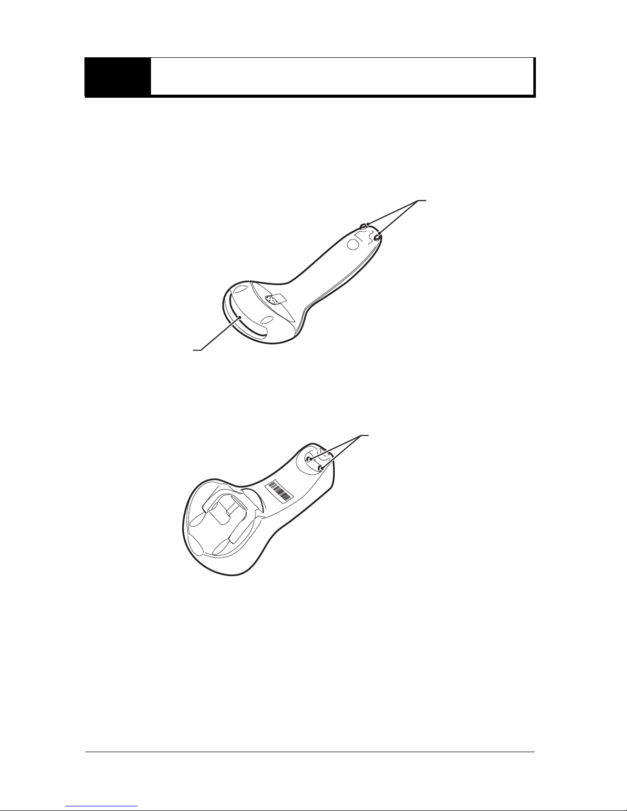
Clean the following parts on the BL-N90/N90K and the communication unit periodically.
• BL-N90/N90K
Clean the laser emitter/receiver and the charging terminals.
Charging
terminals
Laser emitter/
receiver
• Communication unit
Clean the charging terminals.
Charging
terminals
b Cleaning method
Laser emitter/receiver : Clean the surface using an eyeglass cleaning cloth or a soft cloth
that has been dampened with a specialty cleaner for plastics.
Charging terminals : Wipe the surface gently using a soft cloth moistened with
alcohol.
6
Page 9

1
Overview
This chapter describes names and functions of each part of the
items in the package.
1-1 Checking the Package Contents . . . . . . . . . . . 1-2
1-2 Part Names. . . . . . . . . . . . . . . . . . . . . . . . . . . . . 1-5
1
Overview
1-1
Page 10
1-1 Checking the Package Contents
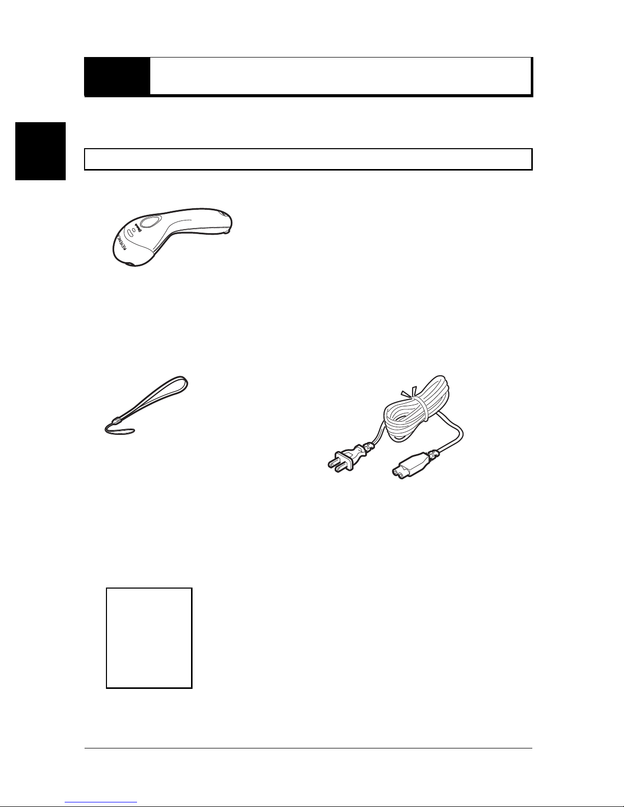
The BL-N90/N90K series comes with the following items. Check that all of the items are
included.
1
Wireless Hand-held Barcode Reader BL-N90/N90K
Overview
b BL-N90/N90K barcode reader: 1
b Strap: 1 b AC cable: 1
Supplies power by using the AC adapter
of the communication unit.
b User's Manual: 1
1-2
This cable is not included in the BL-N90K.
*
Please prepare one separately.
* This cable can be used in Japan only.
Page 11

1-1 Checking the Package Contents
A
Communication Unit BL-N9R/N9V/N9UB
The following models are available for each communication interface:
Model Communication interface
BL-N9R RS-232C communication unit
1
BL-N9V Keyboard interface communication unit
BL-N9UB USB communication unit
b Communication unit: 1
BL-N9R BL-N9V
BL-N9UB
Overview
b AC adapter: 1 b Wall mount screw: 2
Used to mount the communication unit on a wall.
b Cup holder b Instruction Manual: 1
ttach this holder to the
communication unit to
secure the BL-N90/
N90K when the
communication unit is
used on a wall.
1-3
Page 12
1
1-1 Checking the Package Contents
Option
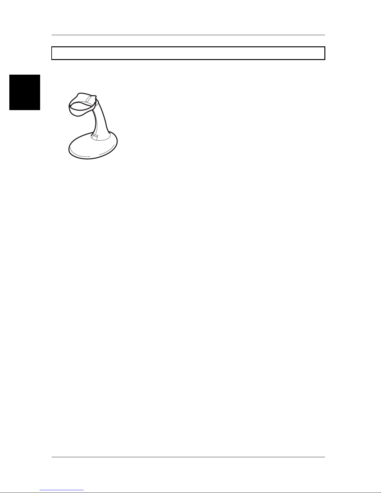
b Stand OP-82191
Used to fix the BL-N90/N90K on a desktop to read barcodes by bringing them close to it.
Overview
1-4
Page 13
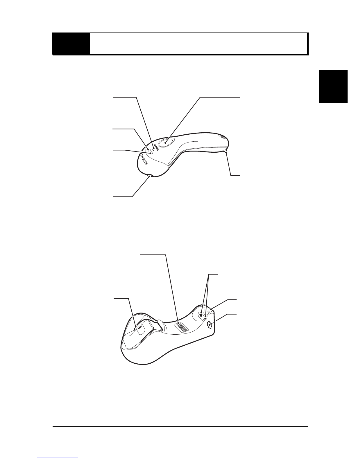
1-2 Part Names
This chapter describes names and jobs of each part of the BL-N90/N90K Series.
b BL-N90/N90K
Ye llow operation
check LED
White operation
check LED
Blue operation
check LED
Emitter/receiver:
Emits and
receives laser light.
Tr i gger switch:
Use the switch to read
a barcode.
Charging terminals
1
Overview
b Communication unit
BD address barcode
Read this barcode for
establishing connection (pairing)
with the BL-N90/N90K.
Wall mount hook:
In applications
where wall mount
becomes
necessary, the
hook will secure
the scanner into
place.
:
Charging terminals
Blue operation check LED
Page button:
When the scanner
associated with the
cradle cannot be found,
press the page button;
the scanner will begin
beeping and the blue
and yellow LEDs will
flash alternately.Press
the page button again to
stop the beep and LED
flashing.
1-5
Page 14
1-2 Part Names
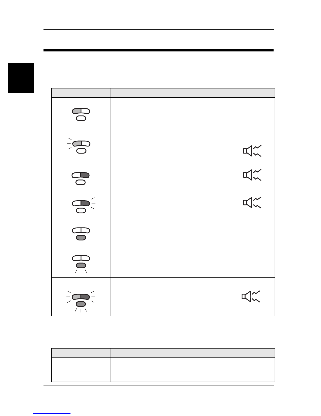
t
Operation check LEDs
The LEDs illuminate or flash for each operation as shown in the following table.
A beep may sound at the same time for some operations.
1
b BL-N90/N90K
Overview
LED lighting/flashing BL-N90/N90K status Beep*
Flashes in white.
Lights in blue
Flashes in blue
Lights in white.
Lights in yellow.
Emitting laser. –
•Not wirelessly connected with the communication unit.
•Out of the wireless communication range.
Wireless communication is cut.
Sending data to the communication unit.
Establishing wireless communication (flashes three
times).
Charging complete. –
–
2
1
3
Flashes in yellow.
Mounted on the communication unit: Being charged. –
Flashes in blue, white,
and yellow.
When checking the association using the page
button on the communication unit.
Press the page button again to stop.
* The number beside the beep mark indicates the number of beeps.
b Communication unit
LED lighting/flashing Communication unit status
Lights in blue The wireless connection is established and the unit can be used.
Flashes in blue
1-6
•Wireless connection is not established with the BL-N90/N90K.
•Out of the wireless communication range.
Repea
Page 15

2
First Steps
This chapter describes the procedures for connecting the
BL-N90/N90K to use for the first time.
2-1 The Setup Procedure . . . . . . . . . . . . . . . . . . . . 2-2
2-2 Connecting the Power Cable to the
Communication Unit . . . . . . . . . . . . . . . . . . . . . 2-3
2-3 Connecting the Communication Unit . . . . . . . 2-5
2
First Steps
2-4 Charging the BL-N90/N90K. . . . . . . . . . . . . . . 2-11
2-5
2-6 Initial Setup for the BL-N90/N90K . . . . . . . . . 2-15
2-7 Reading a Barcode . . . . . . . . . . . . . . . . . . . . . 2-16
2-8 Wireless Connection Environment . . . . . . . . 2-18
Establishing a Connection
. . . . . . . . . . . . . . . . 2-13
2-1
Page 16
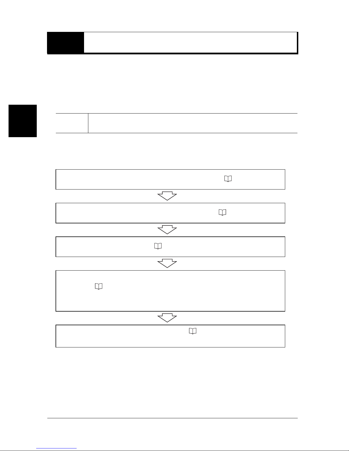
2-1 The Setup Procedure
Before using the BL-N90/N90K, the following connections must be set up.
Performing these connections establishes the following communications, enabling the BLN90/N90K for use.
• Communication unit to PC connection: Wired transmission
• BL-N90/N90K to communication unit connection: Wireless transmission (Bluetooth)
2
First Steps
b First steps
Note
1
2
3
4
After connecting the communication unit to the computer, be sure to charge
the BL-N90/N90K before use.
Connect the power cable to the communication unit. ( page 2-3).
Connect the communication unit to your computer ( page 2-5).
Charge the BL-N90/N90K ( page 2-11).
Establish a connection between the BL-N90/N90K and the communication
unit ( page 2-13).
Use the BL-N90/N90K to read the BD address barcode attached to the
communication unit.
Initialize settings for the BL-N90/N90K. ( page 2-15).
5
2-2
Read the initialization barcode using the BL-N90/N90K.
Page 17
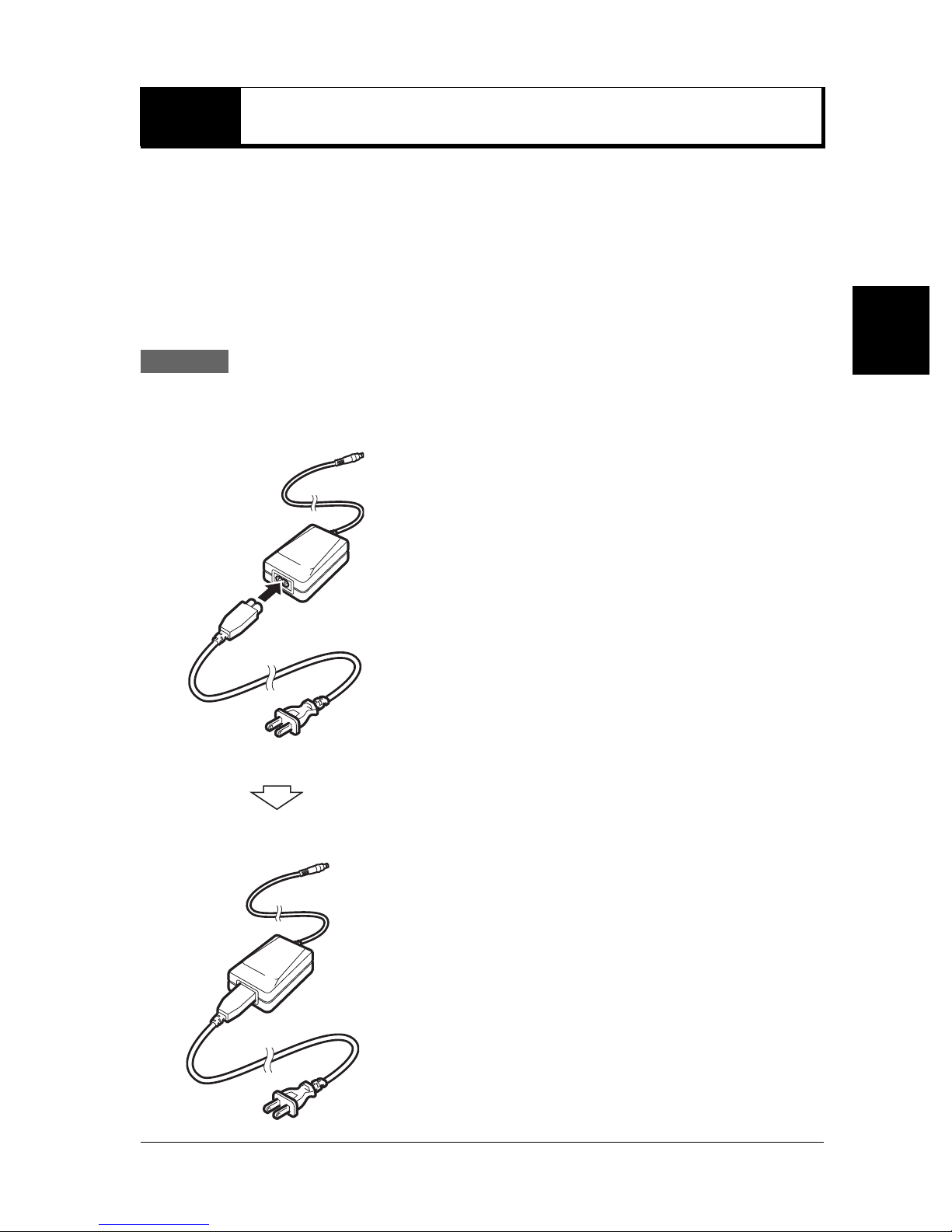
2-2
Connect the power cable to the communication unit before use.
Connecting the Power Cable to the Communication Unit
b Included parts
• AC cable for the BL-N90
(The AC cable for the BL-N90K is not included. Please prepare one separately.)
• Communication unit
• AC adaptor for the communication unit
Procedure
1 Connect the AC cable to the AC adaptor.
2
First Steps
2-3
Page 18
2
2-2 Connecting the Power Cable to the Communication Unit
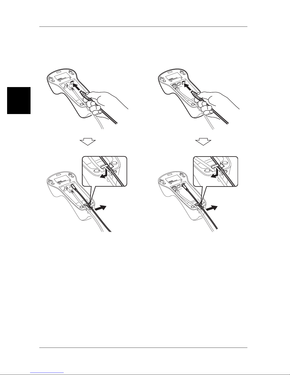
2 Connect the AC adapter to the AC connector on the back of the communication unit.
After connecting the AC adaptor, snap the cable behind the hook.
BL-N9UB BL-N9V/N9R
First Steps
1
2
1
2
2-4
Page 19
2-3 Connecting the Communication Unit
After connecting the power cable to the communication unit, connect the communication unit
to your computer using the interface provided.
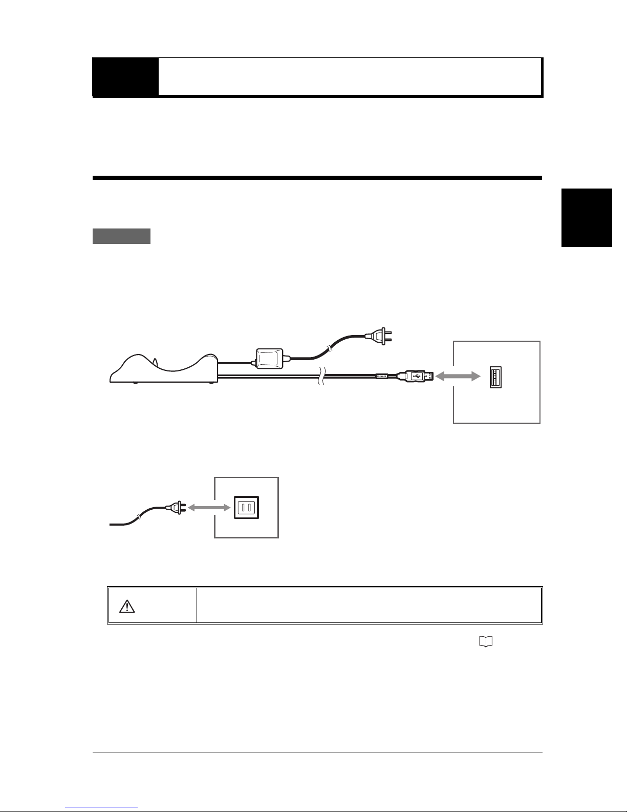
Connecting the BL-N9UB to your Computer
Use the USB cable to connect the communication unit to your computer.
The barcode reader is compatible with Windows XP/2000/98.
Procedure
1 Tu r n on your computer.
2 Connect the communication unit's interface cable to the USB port on your computer.
BL-N9UB
Computer
2
First Steps
USB port
(tyep A)
3 Connect the power cable to an AC outlet, and turn on the communication unit.
The blue LED on the communication unit will flash.
•
CAUTION
After connecting the device to your computer for the first time, install the USB driver ( page 2-6).
Be sure to use the AC adaptor provided with the device. Connecting to other
power sources may cause electric shock, fire or product damage.
2-5
Page 20
2-3 Connecting the Communication Unit
Installing the USB Driver
When BL-N9UB is first connected to a computer running Windows 98, the USB driver
installation screen appears. Install the driver by following the directions given on the screen.
(This procedure is not necessary when using a computer running Windows XP/2000).
2
Note
Procedure
First Steps
Connect the barcode reader after turning on the computer. If the barcode reader is
connected with the power off, turn the computer on.
1 The "Add New Hardware Wizard" dialog appears and the message "This window searches
for new drivers for:USB human interface device" is displayed. Click on the [Next] button.
2 The message "What do you want Windows to do?" is displayed. Select [Search for the best
driver for your device (Recommended).] and click on the [Next] button.
3 Click on the [Next] button. "USB human interface device" is displayed and the message
"Windows driver search for the device:" appears. Click on the [Next] button.
Note
The CD-ROM (Windows) may be required depending on the computer environment.
4 Windows begins installing the driver. When installation is complete, the message
"Windows has finished installing the software that your new hardware device requires."
appears. Click on the [Finish] button.
2-6
Page 21
2-3 Connecting the Communication Unit
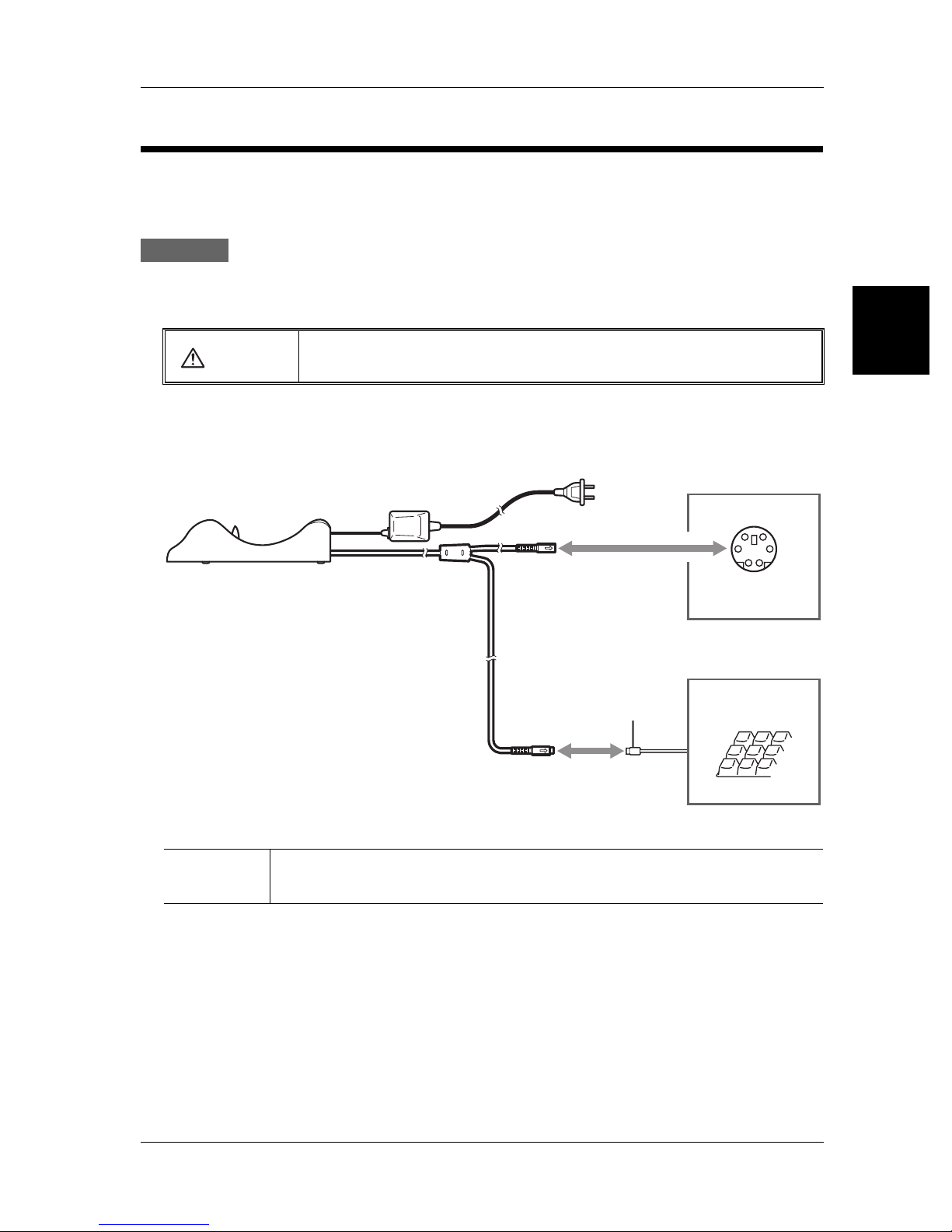
Connecting the BL-N9V to your Computer
Use the keyboard interface to connect the communication unit to your computer. Compatible
computers include PC/AT (DOS/V) machines.
Procedure
1 Tu r n o ff the computer.
CAUTION
Do not remove the cables while the computer is turned on.
This could cause damage to the computer and the barcode reader.
2 Connect the communication unit's interface cable to your computer's keyboard connector,
as indicated in the diagram.
BL-N9V
PS/2 connector
Computer
PS/2 connector
(mini-DIN 6-pin)
Keyboard
2
First Steps
Reference
When connecting a keyboard connector plug to an AT connector, use a commercial
keyboard conversion adapter for the connection.
2-7
Page 22
2-3 Connecting the Communication Unit
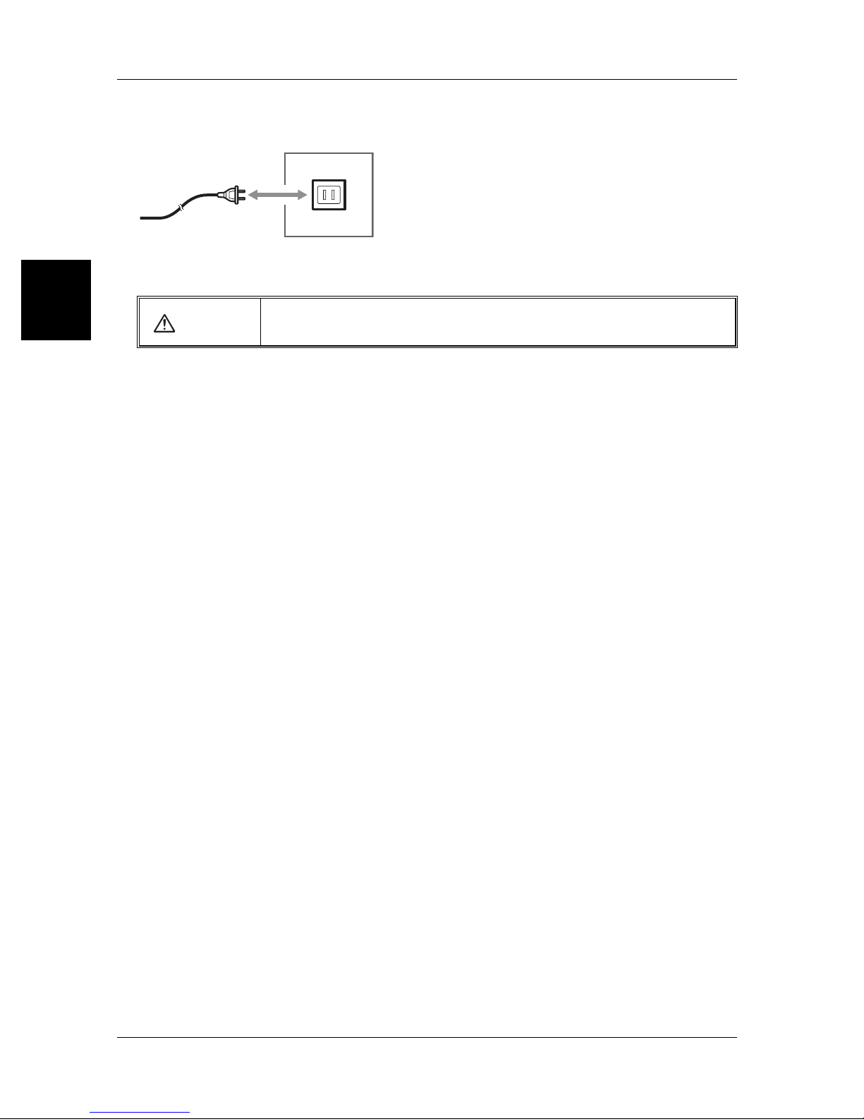
3 Connect the power cable to an AC outlet, and turn on the communication unit.
The blue LED on the communication unit will flash.
2
CAUTION
First Steps
4 Tu rn on your computer.
•
Be sure to use the AC adaptor provided with the device. Connecting to other
power sources may cause electric shock, fire or product damage.
2-8
Page 23
2-3 Connecting the Communication Unit
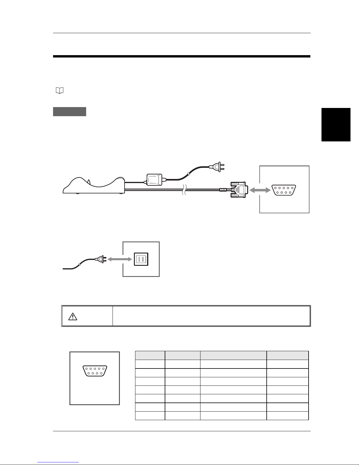
Connecting the BL-N9R to your Computer
A communication unit with an RS-232C interface may be used in conjunction with an RS232C enabled device. This section explains procedures for connecting the barcode reader
to a computer, as well as connecting the barcode reader to an AutoID data controller DV-90
(
page 2-10).
Procedure
1 Tu r n on your computer.
2 Connect the communication unit's interface cable to the RS-232C port on your computer.
BL-N9R
Computer
RS-232C
(D-sub 9-pin)
3 Connect the power cable to an AC outlet, and turn on the communication unit.
The blue LED on the communication unit will flash.
2
First Steps
CAUTION
•
b RS-232C pin configuration of the BL-N9R
54321
9876
D-sub 9-pin (female)
#4-40 screws
Be sure to use the AC adaptor provided with the device. Connecting to other
power sources may cause electric shock, fire or product damage.
Pin No. Symbol Description
2SD (TXD)Sends data Output
3RD (RXD)Receives data Input
4-
5SGSignal ground -
6-
7CS (CTS)Send OK Input
8RS (RTS)Send request Output
Do not make any connection
Do not make any connection
Signal direction
-
-
2-9
Page 24
2
2-3 Connecting the Communication Unit
b Communication settings
Factory settings for the BL-N90 are given below. The settings can be changed. Make sure
that the settings for BL-N90/N90K and the connected computer are the same.
• Baud rate : 9600 bit/s
• Data length : 7 bits
• Parity : Even
• Stop bit : 1 bit
• Communication protocol: No protocol
First Steps
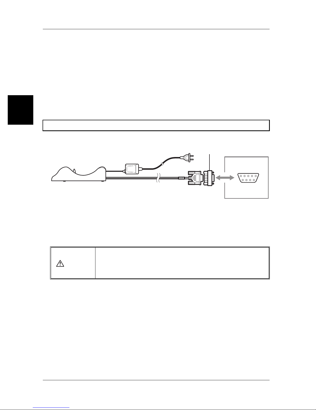
Connecting the DV-90
To connect the device to a DV-90, an adaptor like the diagram below is required.
Conversion connector
BL-N9R
The following adaptor is recommended.
• Manufacturer : Elecom
• Product Name : Serial Reverse Adaptor
• Model : AD-R9
•
Be sure to use the AC adaptor provided with the device. Connecting to other
CAUTION
power sources may cause electric shock, fire or product damage.
• Power is supplied by the AC adaptor. The D-sub connector does not supply
power.
DV-90
RS-232C
(D-sub 9-pin)
2-10
Page 25
2-4 Charging the BL-N90/N90K
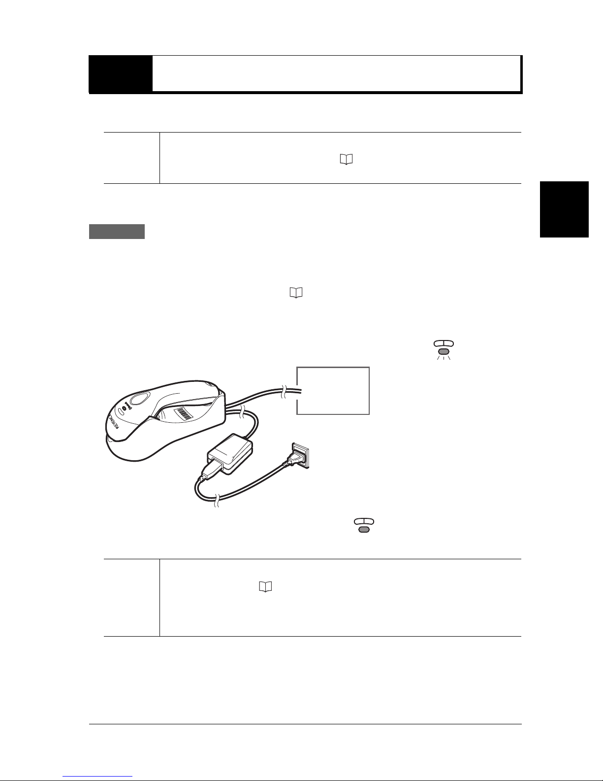
The communication unit is used to charge the BL-N90/N90K.
The barcode reader is shipped with zero charge. Please charge the device before use.
Note
The barcode reader may be used to scan ( page 2-13) after a charge of just 10
minutes.
b How to charge
Procedure
1 Connect the communication unit to your computer using the appropriate connection
method, and make sure both sides are powered on.
For details on connection methods, refer to "Connecting the Communication Unit" on page 2-5.
2 Set the BL-N90/N90K into the communication unit securely, to ensure that the charging
terminals stay in place.
As the unit begins to charge, the yellow LED on the scanner begins to flash .
To computer
2
First Steps
Charging is complete once the yellow LED stops blinking .
A full charge takes approximately 4 hours.
Please periodically clean the charging terminals on the BL-N90/N90K and the
•
communication unit ( "Maintenance" (Page 6)).
Note
Dirt in the terminals may interfere with charging.
• The BL-N90/N90K can be configured to sound an alarm when it is unable to charge
properly, such as when the charging terminals are misaligned.
2-11
Page 26
2
2-4 Charging the BL-N90/N90K
Rechargeable Batteries for the BL-N90/N90K
The BL-N90/N90K sounds an alarm when the battery is low.
When using the scanner, be mindful of the alarm and always maintain a charge.
b Battery low alarm
When the BL-N90/N90K battery level gets low, the following alarms are sounded.
• Each time a barcode is read, a beep sounds two times
•
First Steps
Reference
• If the laser does not light even when pressing the "Trigger" switch, then the
b Continuous use capacity
The following table offers estimates of how long the BL-N90/N90K can be used
continuously on a full charge.
If the "Trigger" switch is pressed but the laser light is short, or if the laser does
not light when reading a barcode, the battery may be low.
battery is completely depleted.
2
Usage Condition Estimated Continuous Use Length
One scan every 10 seconds Approx. 10 hours
One scan every 5 seconds Approx. 8.5 hours
Idle with full charge
Sleep mode with full charge
*
Since the BL-N90/N90K scanner and the communication unit are continuously communicating
wirelessly, battery power is depleted even when the BL-N90/N90K is not in use.
•
When not in use, it is recommended that you set the BL-N90/N90K in the communication unit.
• When not using the device for long periods, enabling sleep mode interrupts the wireless
communication, thereby saving battery power.
Note
*
*
The continuous use times listed above are estimates. Actual times may vary.
•
• If the continuous use times decrease remarkably, then it is time to replace the
batteries. Contact your nearest KEYENCE office.
Approx. 12 hours
Approx. 54 hours
b Charging time
A fully depleted (no charge) battery takes approximately 4 hours to fully charge.
2-12
Page 27
2-5
The BL-N90/N90K and the communication unit communicate as a pair. This section describes
how to establish a connection between the BL-N90/N90K and the communication unit.
Establishing a Connection
Note
Procedure
Note
Perform the following operation with the communication unit connected to your
computer ( page 2-5).
The following symptoms indicate that a connection is not established.
• The blue LED on the scanner is flashing
• The blue LED on the communication unit is flashing
At this stage, perform the following steps.
Note that even when using multiple BL-N90/N90K scanners, each scanner can only
communicate with its pair communication unit ( page 2-14).
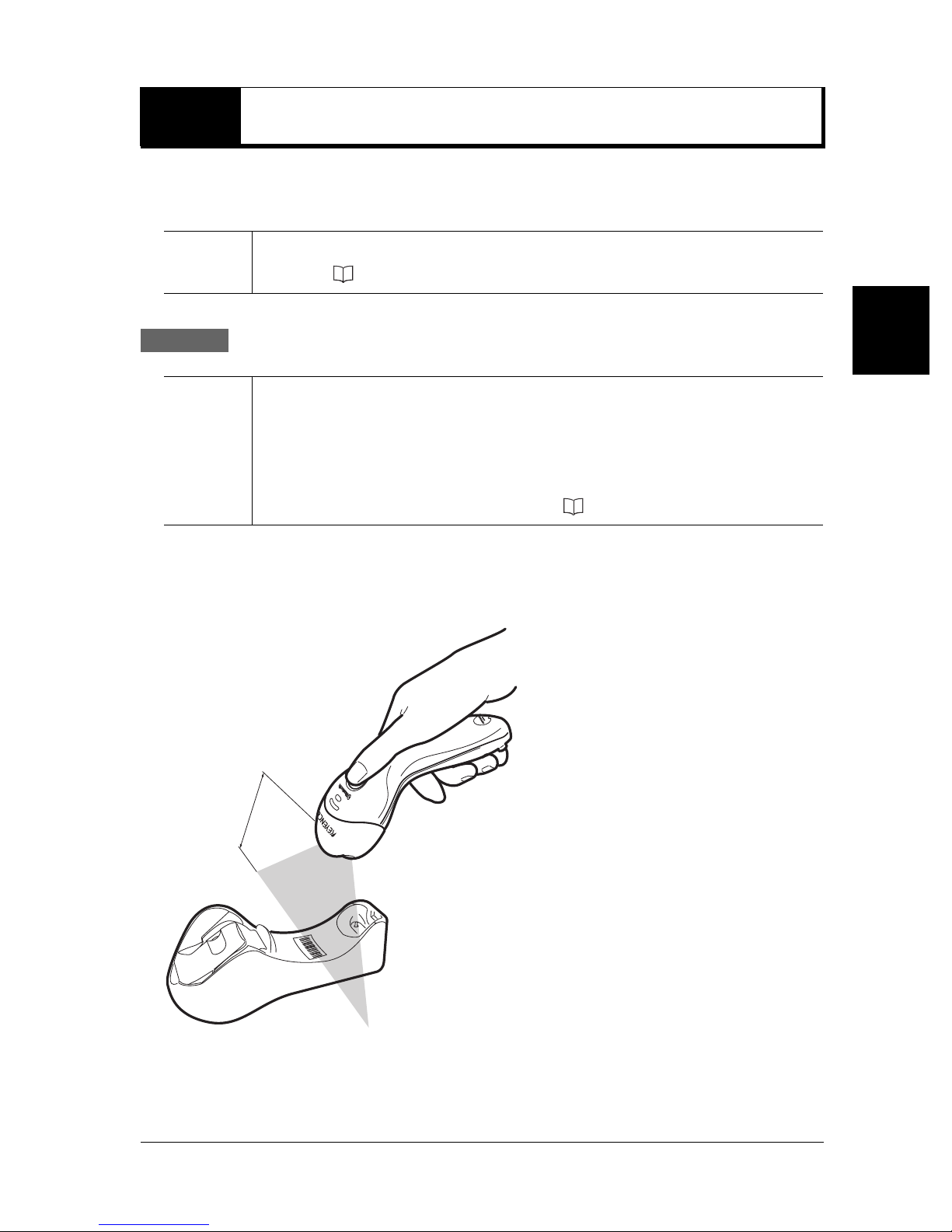
1 Press the "Trigger" switch to activate the laser.
2 Scan the barcode attached to the communication unit.
2
First Steps
100mm
After 10 to 30 seconds, a connection will be established. Once a connection is established, the
devices will be in the following state:
• The blue LED on the scanner is lit.
• The blue LED on the communication unit is lit.
2-13
Page 28
2
2-5 Establishing a Connection
Notes About Establishing a Connection Between the
Scanner and the Communication Unit
b Reading a barcode
The BL-N90/N90K cannot read a barcode unless a connection has been established with
the communication unit.
(A beep will sound twice.)
b Using multiple BL-N90/N90K barcode readers
First Steps
• Only the connected barcode reader and communication unit pair can communicate with
one another.
• If multiple BL-N90/N90K barcode readers scan the same communication unit barcode,
only the first barcode reader to scan the communication unit can communicate with it.
To c h ange the pairing, follow the procedure below entitled "Swapping out the BL-N90/
N90K".
b Swapping out the BL-N90/N90K
When swapping one BL-N90/N90K barcode reader for another, follow the procedure
below.
Procedure
1
Hold down the trigger switch on the paired BL-N90/N90K for about 10 seconds to enable
sleep mode.
A beep will sound as sleep mode is enabled. ( page 1-6)
During sleep mode, the wireless connection is disabled, causing the blue LED on the
communication unit to blink. This connection must be disabled in order for the communication
unit to pair with another BL-N90/N90K.
2 Use the second BL-N90/N90K to scan the barcode of the communication unit.
3 Scan the initialization barcode. ( page 2-15)
2-14
Page 29
2-6
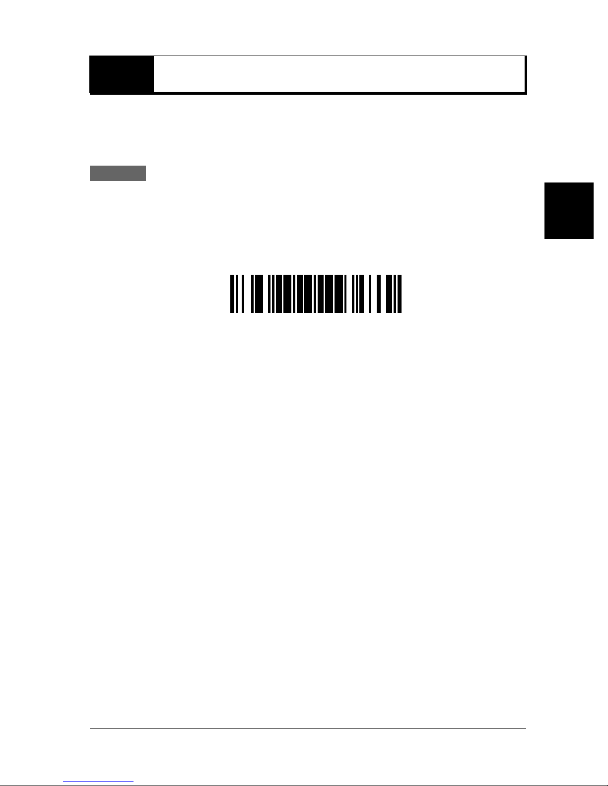
After establishing a connection between the BL-N90/N90K and the communication unit, be
sure to initialize its configuration. This ensures that the scanner's configuration is initialized to
match the interface type of the communication unit.
Procedure
Initial Setup for the BL-N90/N90K
1 Press the "Trigger" switch to activate the laser.
2 With the laser light about 100 mm from the page, scan the "Initialization" barcode below.
Once scanning of the "Initialization" barcode is complete, a beep will sound 3 times.
<Initialize>
2
First Steps
2-15
Page 30
2
2-7 Reading a Barcode
This section describes the basic barcode scanning operations.
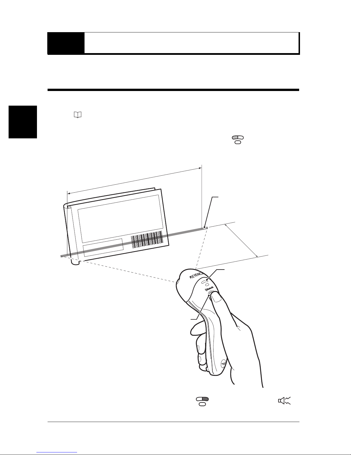
Scanning a Barcode
The BL-N90/N90K is able to read barcodes when it is connected wirelessly to the communication unit.
The wireless connection can be verified by checking that the blue LED on the communication
unit is lit ( page 1-6).
1 Press the "Trigger" switch to activate the laser.
First Steps
As the laser is activated, the blue LED on the BL-N90/N90K lights up .
2 Aim the laser to cover the entire barcode.
Readable area
Laser light
Reading distance
100mm
Operation check LED
Trigger switch
3 Once scanning is complete, the white LED lights up, a beep will sound once ,
and data is transmitted to your computer.
1
2-16
Page 31
2-7 Reading a Barcode
b Precautions for reading
• If the BL-N90/N90K communicate with the communication unit wirelessly, then the
barcode will not be read.
(A low-pitched beep will sound twice.)
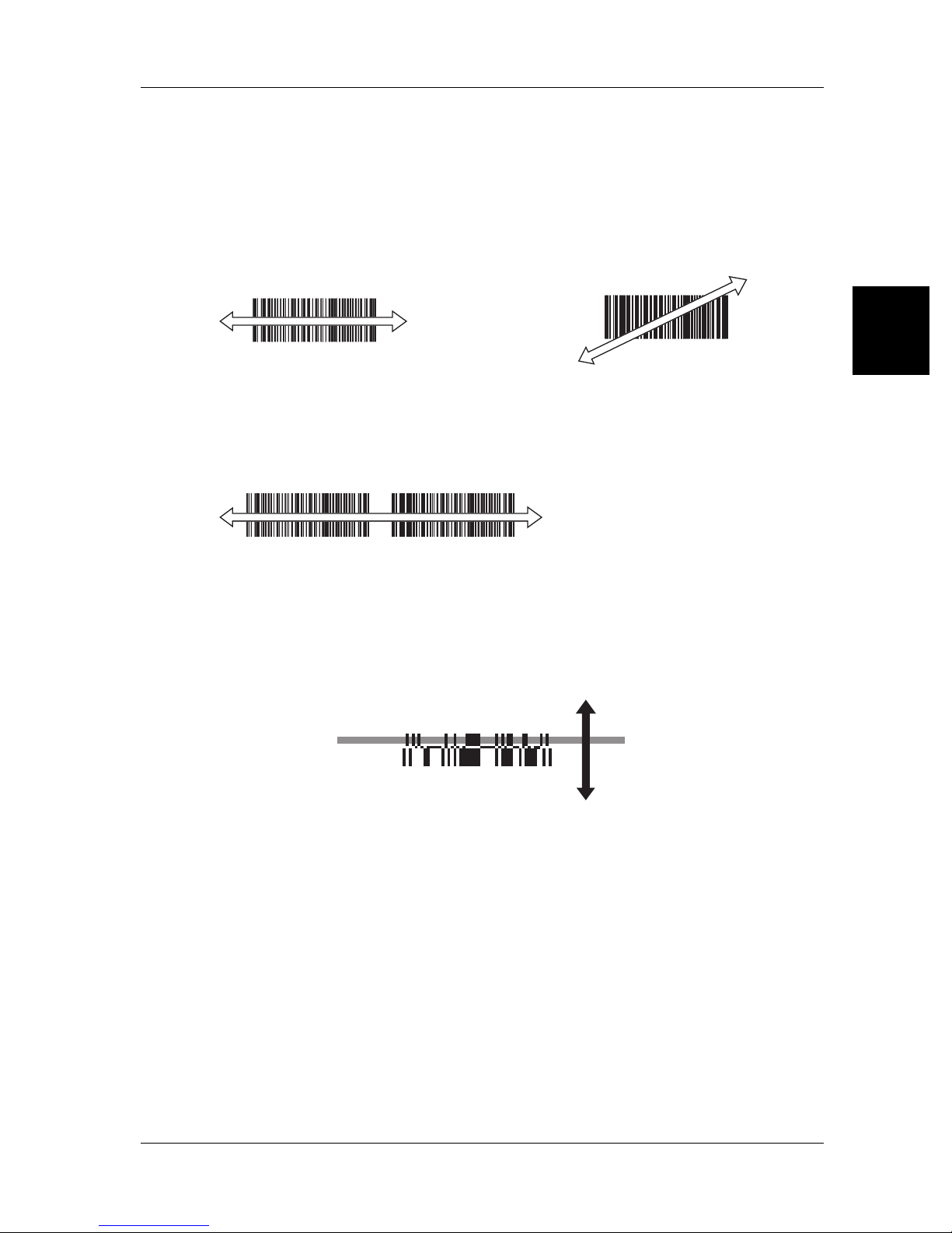
• Be sure to aim the laser to scan the entire length of the barcode.
{ Correct scan × Incorrect scan
• Only shine the laser light on one barcode at a time. Scanning multiple barcodes at once
can lead to scan errors, or barcodes being scanned out of order.
× Incorrect scan
2
First Steps
• Depending on the laser reflection, interior lighting, or barcode label angle, light reflected
from the label may be partially reflected, resulting in scan errors.
In such situations, adjust the label and laser angle or distance.
• When scanning an RSS Stacked barcode, aim the laser and scan from the top of the
barcode to the bottom, or from the bottom to the top.
To p
Bottom
b Caution when using the BL-N9UB/N9V
When using the BL-N9UB/N9V, barcode data read by the BL-N90/N90K is treated as data
entered through the keyboard. In this way, data may be input directly into the running
application, without the need for special drivers.
When using the BL-N9UB/N9V, please note the following:
• Do not try to read a barcode while pressing down a key on the computer's keyboard. Do
not press a key while receiving the data. Data input will not be read correctly.
• If the computer has multiple language settings, make sure that the input mode is set for
single-byte alphanumeric characters.
2-17
Page 32
2
2-8 Wireless Connection Environment
The BL-N90/N90K and the communication unit use Bluetooth Version 1.2 for their wireless
communication. Please use in the following environment.
b Transmission range and surrounding conditions
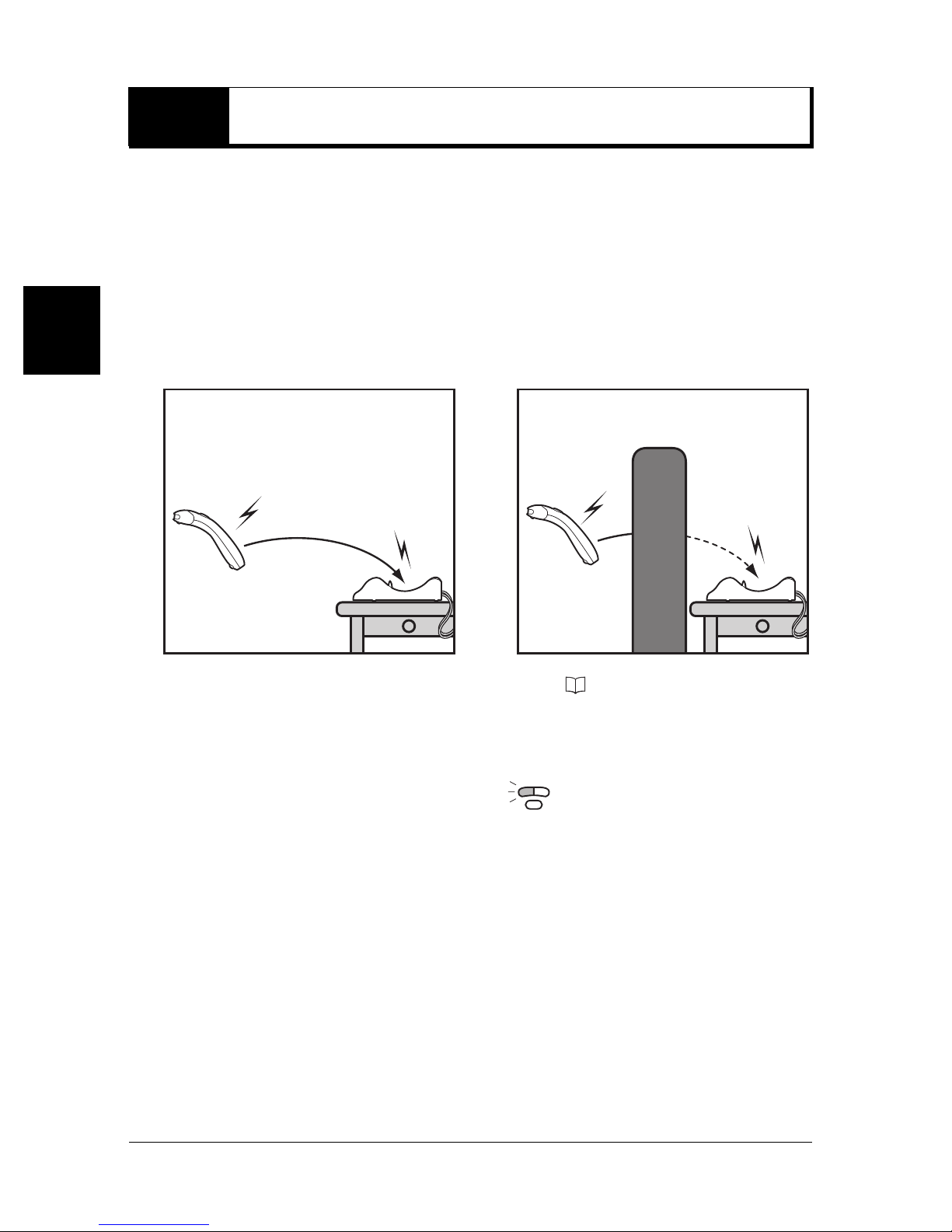
The BL-N90/N90K and the communication unit have a line-of-sight range of approximately
10 meters.
However, obstacles placed between the BL-N90/N90K and the communication unit, such
as concrete or metal, may interrupt the wireless connection. Please use the device in an
environment free of these obstacles.
First Steps
Good
Bad
Obstacle
Also read the notes regarding wireless communication ( Page 3).
b When the wireless connection is interrupted
The following occur when the wireless connection is interrupted:
• The blue LED on the BL-N90/N90K flashes
• The blue LED on the communication unit flashes.
Once a connection can be established again, the BL-N90/N90K and communication unit
automatically reconnect.
• Reconnection may take between 10 to 30 seconds.
• During this time, barcodes cannot be read.
(A low-pitched beep will sound twice.)
.
2-18
Page 33

Appendices
This chapter describes the specifications and outer dimensions.
A-1 Specifications . . . . . . . . . . . . . . . . . . . . . . . . . .A-2
A-2 Dimensions . . . . . . . . . . . . . . . . . . . . . . . . . . . .A-4
Appendices
A-1
Page 34
A-1 Specifications
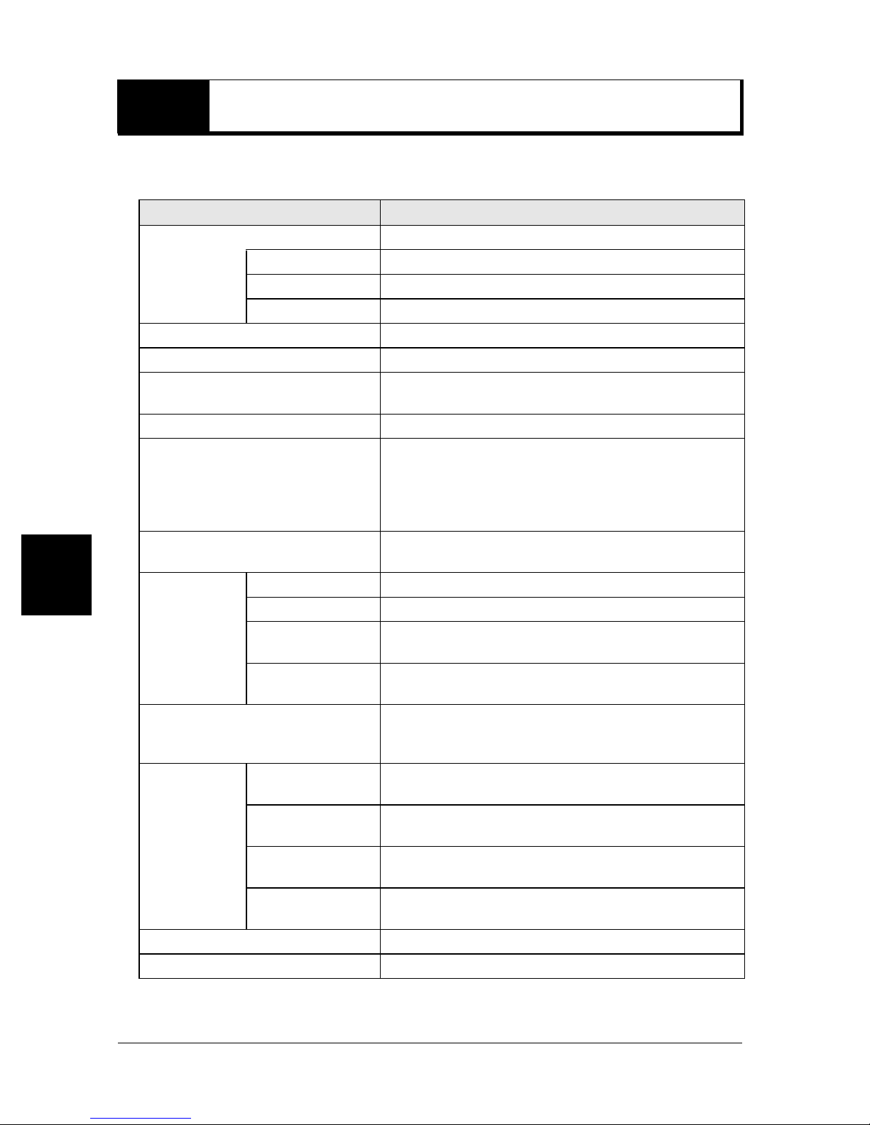
b BL-N90/N90K
Model BL-N90/N90K
Light source Visible semiconductor laser (Wavelength: 650 nm)
Maximum output 350 µW
Pulse width 1.5 ms
Class Class 1 (IEC 68025-1)
Scan rate 72 scans per second
Minimum resolution 0.127 mm
Appendices
Reading distance
PCS 0.35 or more
Supported code
Number of digits for reading
Wireless standard Bluetooth Ver1.2
Wireless
communication
unit
Internal battery
Frequency 2.4 GHz
Transmission
output
Communication
distance
Operating ambient
light
25 to 250 mm (Narrow bar width: 0.5 mm)
0 to 165mm (Narrow bar width: 0.25mm)
JAN/EAN/UPC (A, E), CODE39, CODE128/EAN128,
NW-7, CODE93, ITF, 2of5, RSS-14,
RSS-14 Truncated, RSS-14 Stacked,
RSS-14 Stacked Omnidirectional, RSS Limited,
RSS Expanded, RSS Expanded Stacked
Maximum 40 digits
(Maximum 80 digits with CODE128 or CODE-C)
Class 2 (2.5 mW max.)
10 m visible
Internal lithium ion battery
Continuous use time: 10 hours
Cycle life: 500 times
4800 lx
*1
Operating ambient
Environmental
condition
Outside Dimensions 199 x 77 (44) x 53 mm * Value inside ( ) is the grip
Weight Approx. 200g
*1 The continuous use time with wireless communication reading data once every 10 seconds.
temperature
Operating ambient
humidity
Operating
atmosphere
A-2
0 to 40°C (32 to 104×F), No freezing
35 to 85% RH (No condensation)
No dust or corrosive gas
Page 35
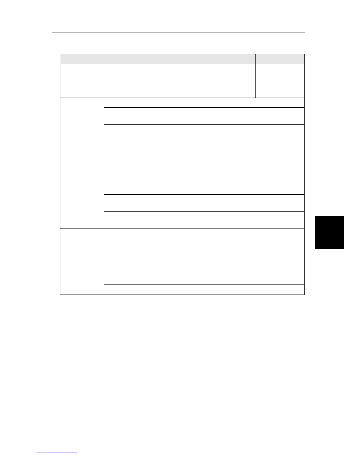
b Communication unit
Model BL-N9R BL-N9V BL-N9UB
A-1 Specifications
Wired
communication
unit
Wireless
communication
unit
Charger
Environmental
condition
Outside Dimensions 204 x 103 x 51 mm
Communication
standard
Connector shape
Wireless standard Bluetooth Ver1.2
Wireless
frequency
Tran sm is sion
output
Communication
distance
Charging method Constant current, constant voltage (CCCV) method
Charging time Approx. 4 hours
Operating ambient
temperature
Operating ambient
humidity
Operating
atmosphere
RS-232C
D-Sub 9-pin
(female)
2.4 GHz
Class 2 (2.5 mW max.)
10 m visible
0 to 40°C (32 to 104×F), No freezing
35 to 85% RH (No condensation)
No dust or corrosive gas
Keyboard
Interface
Mini DIN 6-pin USB (A type)
USB-HID
Ver1.1
*1
Weight Approx. 230 g (Excluding cable)
Input 100-240 V AC, 50/60 Hz
AC adapter
specifications
*1 Compatible OS: Windows98, 2000, XP
Output 5 V DC, Max 2 A
Outside
Dimensions
Weight Approx. 140g
72 x 47 x 27 mm (Excluding cable)
Appendices
A-3
Page 36
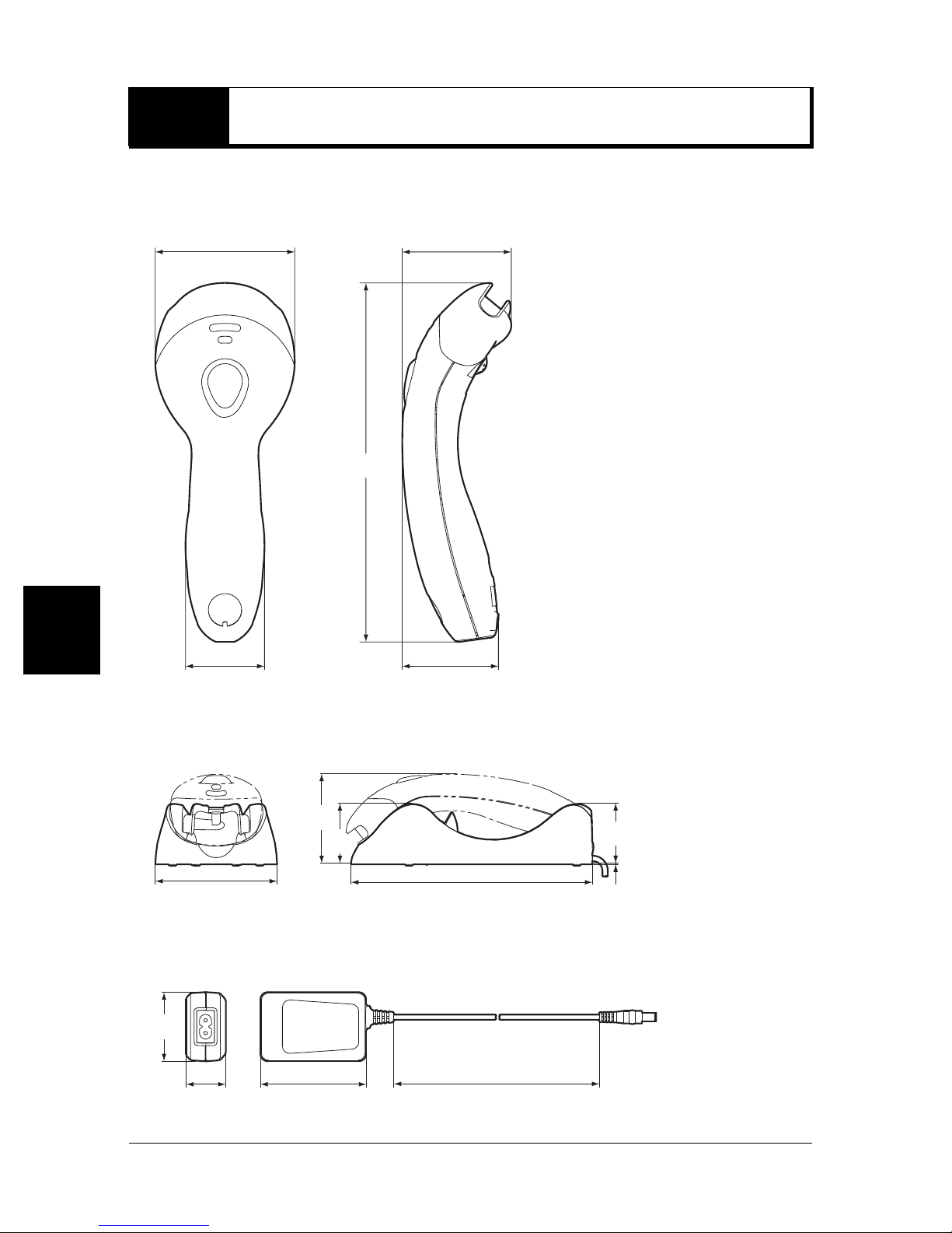
A-2 Dimensions
b BL-N90/N90K (units: mm)
77 60.5
199
Appendices
44
53
b Communication unit (units: mm)
83
51
103
204
b AC adapter (units: mm)
47
7227
1800
51
1
A-4
Page 37
Warranties and Disclaimers
(1) KEYENCE warrants the Products to be free of defects in materials and workmanship for a
period of one (1) year from the date of shipment. If any models or samples were shown to
Buyer, such models or samples were used merely to illustrate the general type and
quality of the Products and not to represent that the Products would necessarily conform
to said models or samples. Any Products found to be defective must be shipped to
KEYENCE with all shipping costs paid by Buyer or offered to KEYENCE for inspection
and examination. Upon examination by KEYENCE, KEYENCE, at its sole option, will
refund the purchase price of, or repair or replace at no charge any Products found to be
defective. This warranty does not apply to any defects resulting from any action of Buyer,
including but not limited to improper installation, improper interfacing, improper repair,
unauthorized modification, misapplication and mishandling, such as exposure to
excessive current, heat, coldness, moisture, vibration or outdoors air. Components which
wear are not warranted.
(2) KEYENCE is pleased to offer suggestions on the use of its various Products. They are
only suggestions, and it is Buyer's responsibility to ascertain the fitness of the Products
for Buyer's intended use. KEYENCE will not be responsible for any damages that may
result from the use of the Products.
(3) The Products and any samples (Products/Samples) supplied to Buyer are not to be used
internally in humans, for human transportation, as safety devices or fail-safe systems,
unless their written specifications state otherwise. Should any Products/Samples be used
in such a manner or misused in any way, KEYENCE assumes no responsibility, and
additionally Buyer will indemnify KEYENCE and hold KEYENCE harmless from any liability
or damage whatsoever arising out of any misuse of the Products/Samples.
(4) OTHER THAN AS STATED HEREIN, THE PRODUCTS/SAMPLES ARE PROVIDED WITH
NO OTHER WARRANTIES WHATSOEVER. ALL EXPRESS, IMPLIED, AND STATUTORY
WARRANTIES, INCLUDING, WITHOUT LIMITATION, THE WARRANTIES OF
MERCHANTABILITY, FITNESS FOR A PARTICULAR PURPOSE, AND NONINFRINGEMENT OF PROPRIETARY RIGHTS, ARE EXPRESSLY DISCLAIMED. IN NO
EVENT SHALL KEYENCE AND ITS AFFILIATED ENTITIES BE LIABLE TO ANY PERSON
OR ENTITY FOR ANY DIRECT, INDIRECT, INCIDENTAL, PUNITIVE, SPECIAL OR
CONSEQUENTIAL DAMAGES (INCLUDING, WITHOUT LIMITATION, ANY DAMAGES
RESULTING FROM LOSS OF USE, BUSINESS INTERRUPTION, LOSS OF
INFORMATION, LOSS OR INACCURACY OF DATA, LOSS OF PROFITS, LOSS OF
SAVINGS, THE COST OF PROCUREMENT OF SUBSTITUTED GOODS, SERVICES OR
TECHNOLOGIES, OR FOR ANY MATTER ARISING OUT OF OR IN CONNECTION WITH
THE USE OR INABILITY TO USE THE PRODUCTS, EVEN IF KEYENCE OR ONE OF ITS
AFFILIATED ENTITIES WAS ADVISED OF A POSSIBLE THIRD PARTY’S CLAIM FOR
DAMAGES OR ANY OTHER CLAIM AGAINST BUYER. In some jurisdictions, some of the
foregoing warranty disclaimers or damage limitations may not apply.
BUYER'S TRANSFER OBLIGATIONS: If the Products/Samples purchased by Buyer are to
be resold or delivered to a third party, Buyer must provide such third party with a copy of this
document, all specifications, manuals, catalogs, leaflets and written information provided to
Buyer pertaining to the Products/Samples.
Page 38
© KEYENCE CORPORATION, 2006 E BL-N90 0106-1 Printed in Japan
 Loading...