

Keyence BL-700 Series, BL-701, BL-740, BL-741, BL-780 User Manual
...
96M1126

Safety Precautions
This instruction manual describes the operation and function of the BL-700. Read
this manual carefully to ensure safe use and maximum performance from your BL-
700. The BL-700 series uses a semiconductor laser as light source. Before using
the product, see "Laser Safety Precautions" on page 1 to learn the safe and correct
method of using the BL-700 series.
Symbols
The following symbols alert you to important messages. Be sure to read these
messages carefully.
Failure to follow instruction may lead to injury. (electric
shock, burn, etc.)
Failure to follow instructions may lead to product damage.
Provides additional information on proper operation.
General Precautions
• At startup and during operation, be sure to monitor the functions and performance of the BL-700.
• We recommend that you take substantial safety measures to avoid any damage
in the event a problem occurs.
• Do not open or modify the BL-700 or use it in any way other than described in
the specifications.
• When the BL-700 is used in combination with other instruments, functions and
performance may be degraded, depending on operating conditions and the
surrounding environment.
• Do not use the BL-700 for the purpose of protecting the human body.
WARNING
CAUTION
Note:
i

ii
Warnings and Cautions Specific to the BL-700
• The BL-700 uses a 5 VDC power supply. Using a different voltage level
may damage the unit.
When using the KEYENCE power supply unit BL-U1, BL-U2, N-42 or N-48,
select the voltage level which can be supplied by the power supply unit. If
a nonconforming power supply is connected, the BL-700 may be damaged.
• The BL-700 is a precision instrument. If the unit is dropped or shocked, it
may be damaged. Take due consideration when transporting or installing
the unit.
• Do not hold the cables when carrying the units. The units may hit each
other and become damaged.
• Before installing the BL-700, read “2.4 Installation” of this manual carefully to
select a suitable installation site.
• You cannot perform any operation for 5 seconds after turning ON the BL-700.
During this time, the motor rotation stabilizes. Wait for a while after turning ON
the BL-700, then start reading or another operation.
• At shipment, the protective seals are affixed to the transmitter and receiver to
avoid fingerprints when mounting the unit. Be sure to remove the seals before
use.
• Do not allow water, oil or dust to adhere to the transmitter and receiver. Adhesion of these materials may cause a reading error. If the surface is contaminated, gently wipe it with a soft cloth moistened with alcohol.
CAUTION
Incorrect
Incorrect
96M1126

iii
Package Contents List
The package contains the following components. Be sure to check the package
contents against the checklist before use.
■ BL-700 package
• BL-700 unit ................................................................................................ 1
• Mounting bracket ......................................................................................1
• Mounting screw ......................................................................................... 2
• Insulating spacer ....................................................................................... 4
• Washer ...................................................................................................... 4
• Laser warning label (Japanese/English/German) ............................... 1 set
■ BL-U1 package
• BL-U1 unit .................................................................................................1
■ BL-U2 package
• BL-U2 unit .................................................................................................1
• D-sub 9-pin connector, connector case .................................................... 1
• Instruction manual ..................................................................................... 1
■ N-42 package
• N-42 unit ...................................................................................................1
• Instruction manual ..................................................................................... 1
■ Setup software, user’s manual (BL-H1WE)
• Setup software (3.5-inch, 1.44 MB) ..........................................................1
• User’s manual (this manual) ..................................................................... 1

iv
BL Series Lineup
■ Laser bar code reader
■ Power supply
■ Other options
• N-400: Multi-drop controller
Used as the master unit when multi-drop linking with the BL series.
• BL-P1E: Handheld programmer specially designed for the BL series.
Used when changing the BL-series or N-400 settings.
• OP-22149 : D-sub 25-pin (male) — D-sub 25-pin (male) RS-232C cross cable
Connects the BL-U1 to the PC (use with OP-25057).
• OP-25057 : D-sub 25-pin — D-sub 9-pin conversion connector
Used in conjunction with OP-22149 when connecting the BL-U1 to
the DOS PC.
• OP-27937: D-sub 9-pin — D-sub 9-pin RS-232C cross cable
Connects the BL-U2 to the DOS PC.
Model Scanning method Readable bar width Reading distance
BL-700 Single 0.15 to 1.0 mm 160 to 370 mm
BL-701 Raster (When narrow width is 0.5 mm)
BL-740 Single 0.25 to 2.0 mm 150 to 750 mm
BL-741 Raster (When narrow width is 1.0 mm)
BL-780 Single 0.32 to 2.0 mm 200 to 1200 mm
BL-781 Raster (When narrow width is 2.0 mm)
Model Supply voltage Interface
BL-U1 100 to 240 VAC RS-232C, RS-422A, RS-485 multi-drop
* Select one of these.
BL-U2 24 VDC RS-232C
N-42 24 VDC RS-422A
N-48 24 VDC RS-485 multi-drop
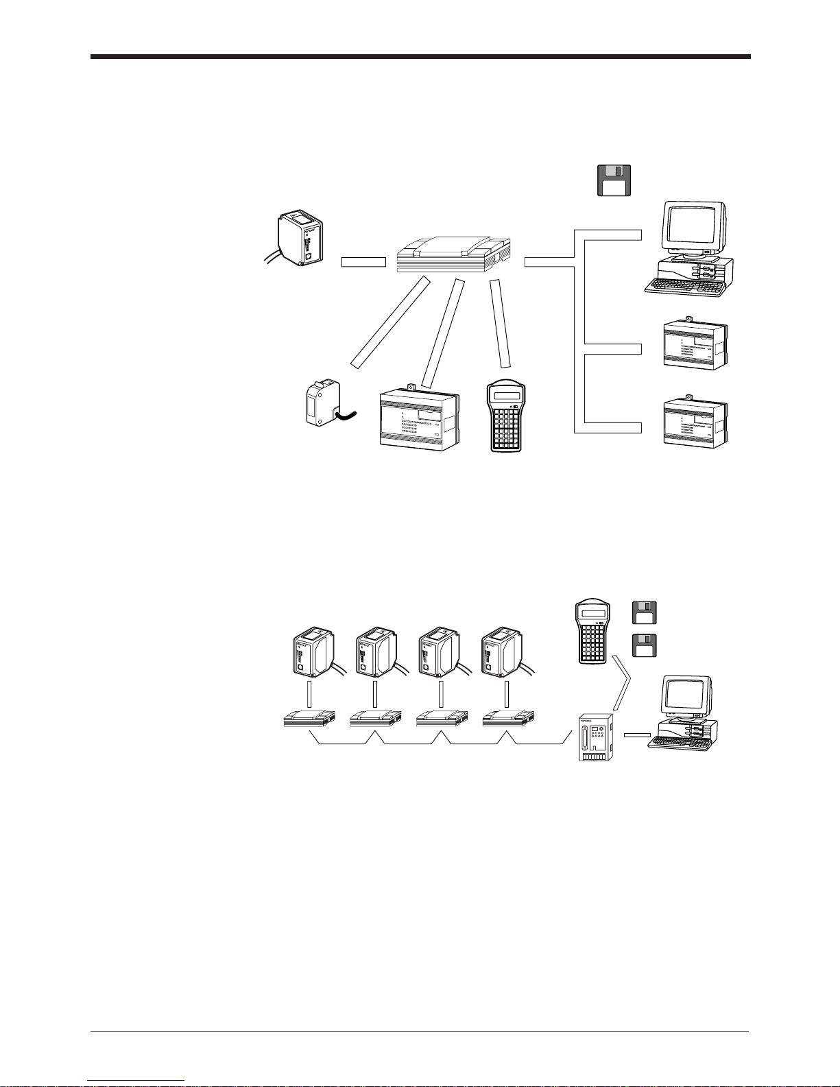
System Configuration
■ When using RS-232C or RS-422A
BL-700
RS-232C
Serial
communication
Serial
communication
BL-U1, BL-U2, N-42
Power supply unit
RS-422A
OK/NG
output
IBM PC/AT
or compatible
Setup software
for BL series
(BL-H1WE)
Windows version
Trigger input
PLC etc. Handheld
programmer BL-P1E
PLC (Link unit)
PLC (RS-232C/422A unit)
PLC link
Timing sensor
LASER ON
STB
OK/NG
TIMING
TEST
BL-700
* Use the BL setup software or the handheld programmer BL-P1E to set the BL
series.
BL-700
Power supply unit
BL-U1, N-48
RS-485
Multi-drop
controller N-400
Handheld programmer
BL-P1E
BL setup software
Windows version
N-400 setup software
Windows version
RS-232C
PC
LASER ON
STB
OK/NG
TIMING
TEST
B
L-70
0
LASER ON
STB
OK/NG
TIMING
TEST
B
L-70
0
LASER ON
STB
OK/NG
TIMING
TEST
B
L-70
0
LASER ON
STB
OK/NG
TIMING
TEST
B
L-70
0
■ When using the RS-485 multi-drop link
* Use the N-400 setup software or handheld programmer BL-P1E to set the multi-
drop controller N-400.
* For system configuration for the multi-drop link, see the “N-400 User’s Manual”.
Also, for connection and operation of the multi-drop link controller, see the “N400 User’s Manual”. The BL-700 User’s Manual does not cover these subjects.
v

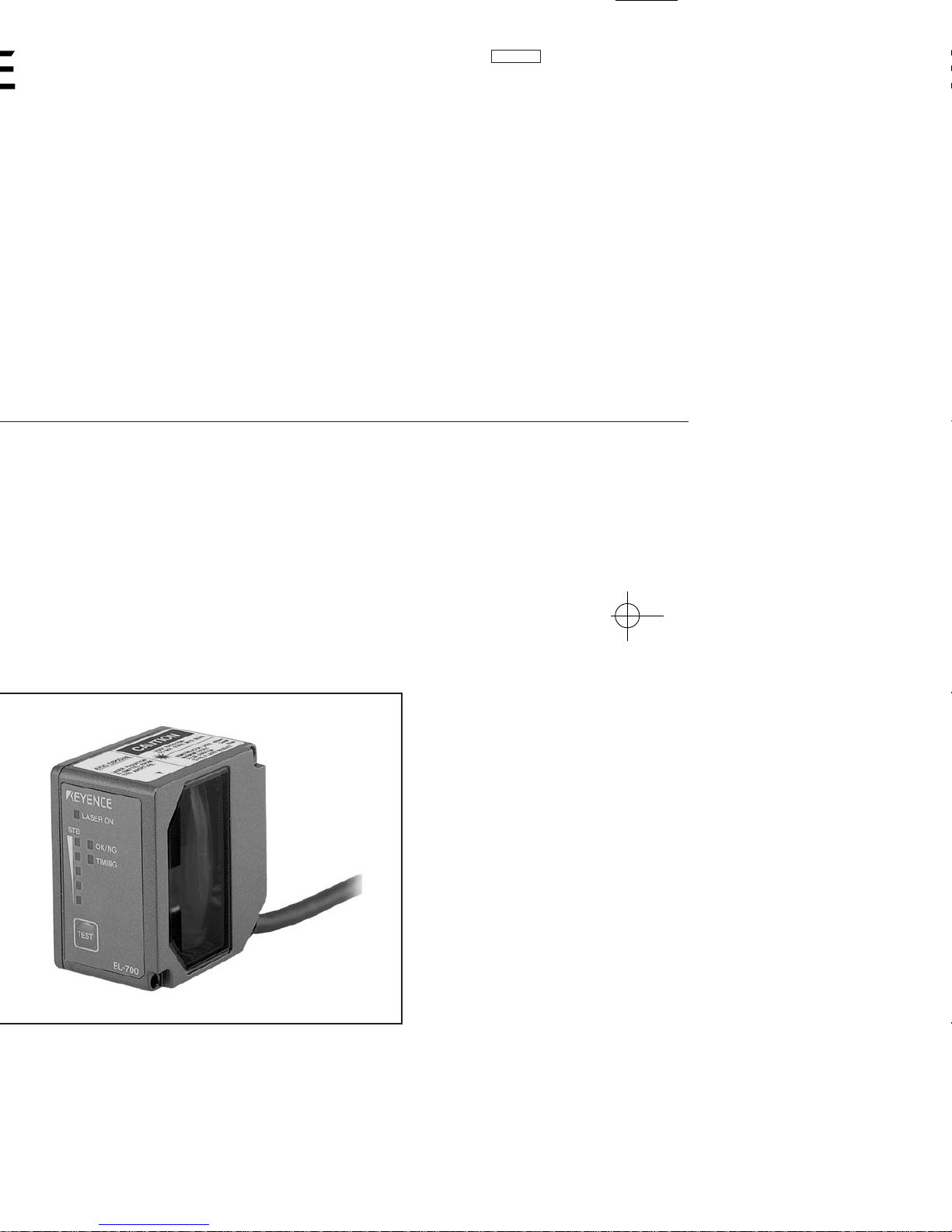
Parts and Functions
BL-700
LASER ON
STB
OK/NG
TIMING
TEST
BL-700
1LASER ON LED
2STABILITY LED
3OK/NG LED
4TIMING LED
5TEST switch
6Transmitter/receiver
7 Cable
No. Name Function
1 LASER ON LED Lit when laser beams are emitted.
2 STABILITY LED Displays the reading stability and the BL-700 operating status.
➮
See P. 64 to P. 65
3 OK/NG LED • When OK output is ON: The green LED lights.
• When NG output is ON: The red LED lights.
4 TIMING LED Lit when trigger input is ON.
5 TEST SWITCH This switch allows the following operations:
• Start the test mode.
• Pressing the switch once reads the bar code once.
• Sets the communication protocol to the initial values when
sending the settings.
➮
See P.75
• Reset the error status.
➮
See P.45
6 Transmitter/receiver Window to emit laser beams and receive reflected lights.
7 Cable Cable length is 1.8 m.
vi
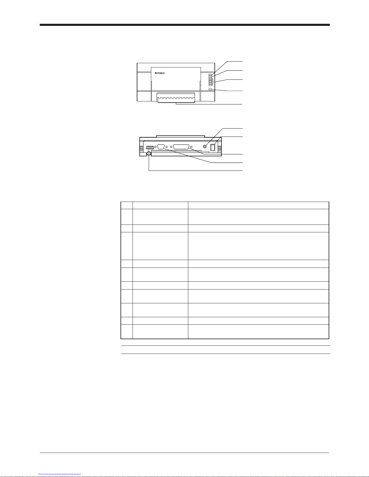
No. Name Function
1 OK/NG LED • When OK output is ON: The green LED lights.
• When NG output is ON: The red LED lights.
2 TIMING LED Lit when trigger input is ON.
3 • Allows you to monitor the communication status of the
RS-232C port.
• The SD, RD, RS and CS indicators are provided in this
order from the top.
4 POWER LED Lit when power is ON.
5 I/O terminal block Includes the trigger input terminal, OK/NG output terminals,
RS-422A terminal and RS-485 terminal.
6 Power switch Turns the power ON/OFF.
7 Use a 100 to 240 VAC (50/60 Hz) power supply.
8 RS-232C port Connect a personal computer to this port. This port is
unused in multi-drop link mode.
9 READER port Connect the BL series to this port.
0 DIP switches Switches the communication port, and turns the terminator
ON/OFF.
Communication status
indicator LEDs
Power supply cable
(2 m)
BL-U1
1 OK/NG LED
2 TIMING LED
3 Communication status indicator
LEDs
4 POWER LED
5 I/O terminal block
6 Power switch
7 Power supply cable (2 m)
8 RS-232C port
9 READER port
0 DIP switches
vii
Note: This product does not comply with EC directives.
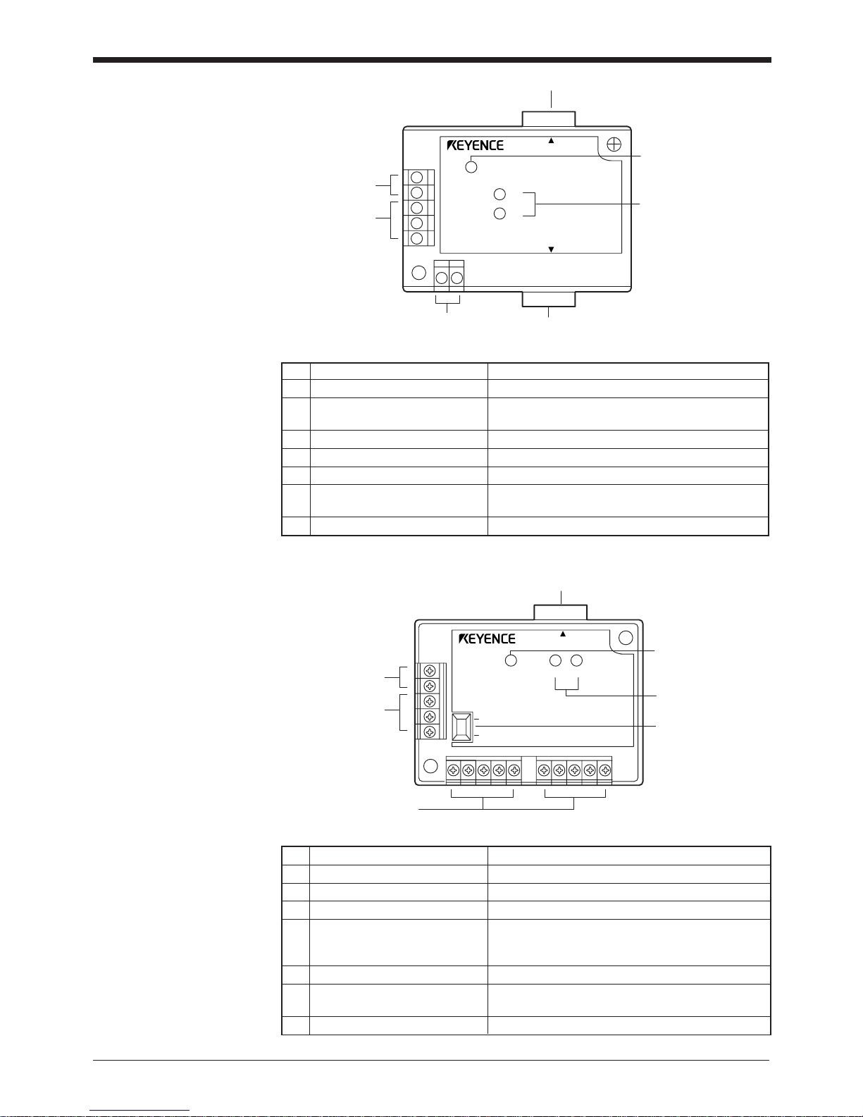
BL-U2
POWER
SD
RD
BL-U2
RS-232C
READER
7 RS-232C port
1 READER port
2 TRIGGER input
terminals
3 OK/NG output
terminals
4 Power supply
terminals
5 POWER LED
6 Communication
status indicator LEDs
5 Terminator switch
1 READER port
4 Power supply terminals
7 POWER LED
6 Communication
status indicator
LEDs
ON
OFF
2 TRIGGER input
terminals
3 OK/NG output
terminals
POWER SD RD
READER
N-42
No. Name Function
1 READER port Connects to a BL series or RS-232C equipment.
2 TRIGGER input terminals Connect to a sensor for trigger input.
3 OK/NG output terminals Output OK/NG signals.
4 Power supply/ interface The 24 VDC power supply terminal and communi-
terminal block cation interface (RS-422A or RS-485) terminal are
provided.
5 Terminator switch Turns ON/OFF the terminator resistor: 100 ).
6 Communication status Indicates the RS-422A or RS-485 communication
status.
7 POWER LED Lights when the power is turned ON
No. Name Function
1 READER port Connects to a BL series bar code reader.
2 TRIGGER Connect to a sensor for input terminals
trigger input.
3 OK/NG output terminals Output OK/NG signals.
4 Power supply terminals Connect to a 24 VDC power supply.
5 POWER LED Turns on when the power is on.
6 Communication status Indicate the communication status of the RS-232C.
indicator LEDs
7 RS-232C port Connects to a personal computer, etc.
viii
Using the Manual
* This manual uses the expression “BL-700” for the BL-700/701/740/741/780/781
unless otherwise specified.
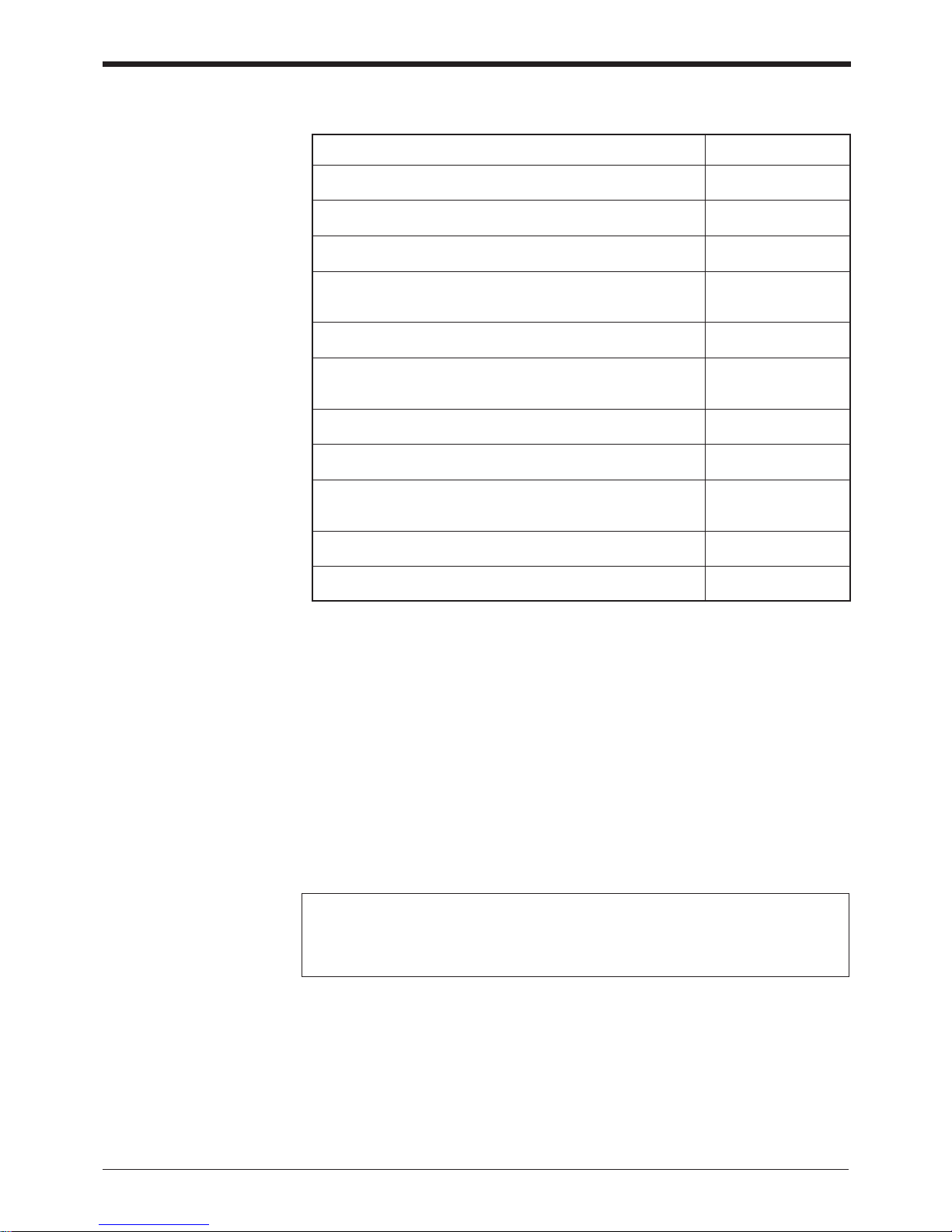
Purpose Reference page
Turn on the trigger timing or wire the RS-232C cable. P.6 to 24
Mount the bar code reader. P.25 to 29
Perform the simple read test. P.40
Check the test mode reading rate or readout count on the P.81
PC screen.
Change the BL-700 settings using the setup software. P.51 –
Change the BL-700 settings through the handheld programmer See the BL-P1E
BL-P1E. User’s Manual.
Communicate with a PC. P.105 –
Control the BL-700 with the PLC link. P.121 –
Use the BL-700 with the multi-drop link. See the N-400
User’s Manual.
Troubleshooting P.136
PLC link communication setup. P.118
Notice
• No part of this instruction manual may be reprinted or reproduced without the
prior written permission of KEYENCE CORPORATION.
• KEYENCE assumes no responsibility for the contents of this manual. No liability
is assumed for damages resulting from a program created by customers.
• The contents of this manual are subject to change without notice.
• “MS”, “Windows” and “Windows95” are registered trademarks of Microsoft,
U.S.A.
• Other company names and product names are registered or nonregistered
trademarks of respective companies.
ix

Contents
Chapter 1 Laser Safety Precautions
1.1 Classification ..........................................................................................2
1.2 Warning Labels ......................................................................................2
1.3 Label Location ........................................................................................3
1.4 Safety Consideration ............................................................................. 4
1.5 Safety Features Provided with the BL-700 Series .............................. 4
Chapter 2 Connection and Installation
2.1 BL-700 connections ............................................................................... 6
2.1.1 Connector pin assignment ........................................................................6
2.1.2 Power supply connections ........................................................................6
2.1.3 Wiring I/O .................................................................................................. 7
2.1.4 RS-232C connection................................................................................. 7
2.2 Connecting BL-U1 and wiring ...............................................................8
2.2.1 Connecting the power supply.................................................................... 8
2.2.2 Connecting the BL-700 .............................................................................8
2.2.3 Setting BL-U1 DIP switches...................................................................... 9
2.2.4 Terminals of I/O terminal block and wiring.............................................. 10
2.2.5 Connecting RS-232C .............................................................................. 11
2.2.6 Wiring the RS-422A ................................................................................14
2.3 Wiring the KEYENCE power supply unit BL-U2/N-42 ....................... 16
2.3.1 Connecting the power supply.................................................................. 16
2.3.2 Connecting the BL-700 to BL-U2/N-42 ...................................................16
2.3.3 Terminals of I/O terminal block and connections .................................... 17
2.3.4 Terminal .................................................................................................. 18
2.3.5 Connecting RS-232C (BL-U2) ................................................................ 18
2.3.6 Connecting the N-42 to RS-422A ........................................................... 21
2.4 Installation ............................................................................................ 23
2.4.1 Operating environment precautions........................................................ 23
2.4.2 Installing the BL-700 Series .................................................................... 25
2.4.3 Installing the BL-U1................................................................................. 27
2.4.4 Installing the BL-U2, N-42....................................................................... 27
x

Chapter 3 Functions for Reading Operation
3.1 Read Operation .................................................................................... 30
3.1.1 Scanning method .................................................................................... 30
3.1.2 Data-send mode ..................................................................................... 32
3.2 Read Modes ..........................................................................................33
3.2.1 Single label read mode ...........................................................................33
3.2.2 Multi-label read mode 1 (Multi 1) ............................................................ 33
3.2.3 Multi-label read mode 2 (Multi 2) ............................................................ 34
3.2.4 Multi-label read mode 3 (Multi 3) ............................................................ 35
3.3 Label Orientation Mode........................................................................... 37
3.4 Test Mode ............................................................................................. 38
3.4.1 Reading rate check mode ....................................................................... 38
3.4.2 Tact check mode..................................................................................... 39
3.4.3 Online test mode..................................................................................... 41
3.5 STABILITY LEDs .................................................................................. 42
3.6 Preset Function (Compare with:) .......................................................44
3.6.1 What is the preset function? ................................................................... 44
3.6.2 Wildcard Symbols (“!” and “?”) ...............................................................45
3.7 Additional Information ......................................................................... 46
3.8 Max. Code Length (Designated Digit ) Output Function .................. 48
Chapter 4 Setup Software
4.1 Installing the Setup Software .............................................................. 50
4.1.1 Installing setup software ......................................................................... 50
4.1.2 Installation procedure.............................................................................. 50
4. 2 Setup Software Operating Procedure ................................................ 52
4.2.1 Operating procedure ............................................................................... 52
4.2.2 Description on each setup screen........................................................... 53
4.2.3 Outline of operation................................................................................. 54
4.3 Details of Setup ....................................................................................56
4.3.1 Setup procedure ..................................................................................... 56
4.3.2 Reading/Saving/Printing File................................................................... 69
4.4 Sending/Receiving Settings ................................................................ 73
4.5 Using Monitor .......................................................................................77
4.6 List of Error Messages ........................................................................ 80
4.7 Example of Printing from the Setup Software ................................... 81
xi

Chapter 5 Serial Communication
5.1 Serial Communication ......................................................................... 84
5.2 Details on Data Communication ......................................................... 85
5.3 Command Communication .................................................................88
5.3.1 Setup of Direct Control Commands ........................................................88
5.3.2 Details on Parameter Setting Commands............................................... 92
Chapter 6 PLC Link
6.1 PLC Link ............................................................................................. 104
6.1.1 List of PLCs used for PLC link ..............................................................104
6.1.2 Devices used for PLC link..................................................................... 105
6.2 Setting the BL-700 and PLC .............................................................. 106
6.2.1 Setting the BL-700 series...................................................................... 106
6.2.2 Setting the PLC..................................................................................... 106
6.3 Device Assignment ............................................................................ 109
6.4 PLC Link Error ....................................................................................116
6.5 Communication Time ........................................................................ 117
Appendices
Appendix A Specifications .......................................................................120
Appendix A.1 Specifications ..........................................................................120
Appendix A.2 Reading range characteristics (Typical) .................................. 122
Appendix A.3 Angular characteristics (Typical) .............................................125
Appendix B. BL-U1 Specifications ............................................................126
Appendix C. BL-U2, N-42 Specifications .................................................. 127
Appendix D. Dimensions ...........................................................................128
Appendix E. Example Program for Serial Communication .................... 131
Appendix F. Sample Program for the PLC Link ......................................132
Appendix G. Troubleshooting ................................................................... 135
Appendix H. CODE93 Specifications ........................................................ 137
Appendix I. CODE128 Specifications ...................................................... 138
Appendix J. Checksum Calculation Method ........................................... 139
Appendix K. ASCII Code Table ..................................................................141
Appendix L. Setup Parameter List ............................................................142
Appendix M. Default Setting List ............................................................... 145
Chapter 7 Warranty
Warranty ..................................................................................................147
xii

xiii

Chapter 1
Laser Safety Precautions
1.1 Classification ........................................................................ 2
1.2 Warning Labels ..................................................................... 2
1.3 Label Location ...................................................................... 3
1.4 Safety Consideration ............................................................4
1.5 Safety Features Provided with the BL-700 Series .............4
Chapter 1 Laser Safety Precautions
1
2
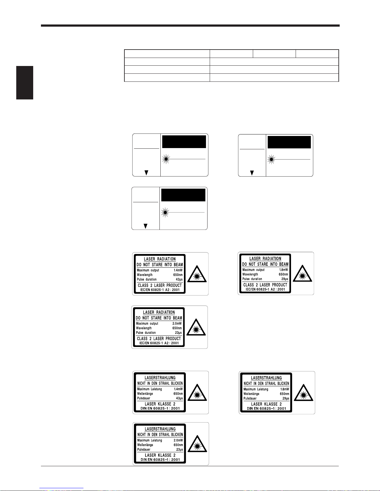
1.1 Classification
Model BL-700/701 BL-740/741 BL-780/781
FDA (CDRH) Class II
IEC/EN 60825-1: 1993 + A2: 2001 Class 2
DIN EN 60825-1 2001 Klasse 2
1.2 Warning Labels
1) Warning labels
■ FDA
BL-700/701 BL-740/741
BL-780/781
■ IEC
BL-700/701 BL-740/741
BL-780/781
■ DIN
BL-700/701 BL-740/741
BL-780/781
LASER RADIATIONDO NOT STARE INTO BEAM
SEMICONDUCTOR LASER 650nm
MAXIMUM OUTPUT 1.4mW
PULSED RADIATION 91 µm
CLASS II LASER PRODUCT
CAUTION
AVOID EXPOSURE
LASER RADIATION
IS EMITTED FROM
THIS APERTURE.
LASER RADIATIONDO NOT STARE INTO BEAM
SEMICONDUCTOR LASER 650nm
MAXIMUM OUTPUT 2.0mW
PULSED RADIATION 91 µm
CLASS II LASER PRODUCT
CAUTION
AVOID EXPOSURE
LASER RADIATION
IS EMITTED FROM
THIS APERTURE.
LASER RADIATIONDO NOT STARE INTO BEAM
SEMICONDUCTOR LASER 650nm
MAXIMUM OUTPUT 1.8mW
PULSED RADIATION 50 µm
CLASS II LASER PRODUCT
CAUTION
AVOID EXPOSURE
LASER RADIATION
IS EMITTED FROM
THIS APERTURE.
Chapter 1 Laser Safety Precautions
1
3
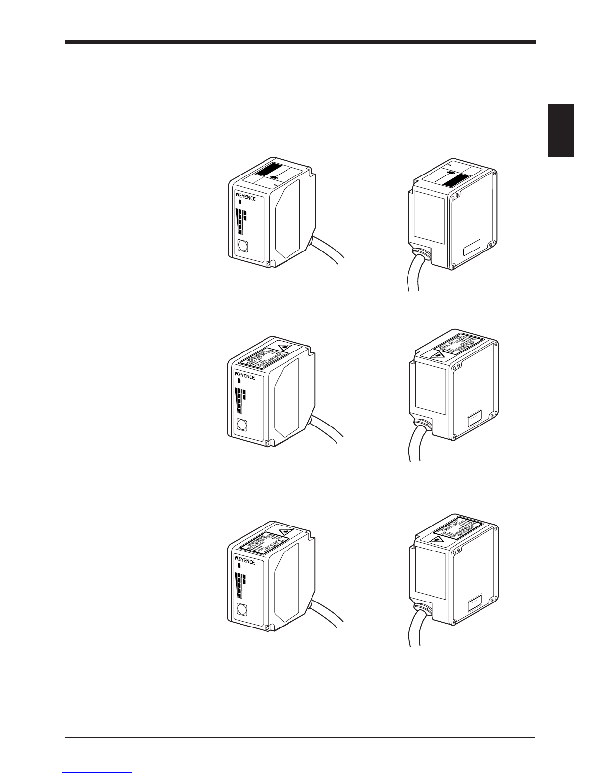
1.3 Labels Location
FDA Warning labels are attached to the sensor head as shown below.
The IEC/DIN Warning labels are packaged with the BL-700 Series. Affix the Warning labels on the sensor head as shown below.
■ FDA
■ IEC
■ DIN
LASER RADIATION-
DO NOT STARE INTO BEAM
SEMICONDUCTOR LASER 650nm
MAXIMUM OUTPUT 1.4mW
PULSED RADIATION 91 µm
CLASS II LASER PRODUCT
CAUTION
AVOID EXPOSURE
LASER RADIATION
IS EM
ITTED FROM
THIS APERTURE.
LASER ON
STB
OK/NG
TIMING
TEST
BL-700
CAUTION LASER RADIATION
WHEN OPEN.
DO NOT
STARE INTO BEAM.
LASER RADIATION-
DO NOT STARE INTO BEAM
SE
M
IC
O
N
D
U
C
T
O
R
LA
S
ER
6
50
nm
M
A
XIM
U
M
O
U
TP
U
T
1.4m
W
P
U
LS
E
D
R
AD
IA
T
IO
N
91
µm
C
LA
SS
II LA
S
E
R
P
R
O
D
U
C
T
CAUTIONCAUTION
AVOID EXPOSURE
LASER RADIATION
IS EMITTED FROM
THIS APERTURE.
LASER ON
STB
OK/NG
TIMING
TEST
BL-700
CAUTION
Laser radiation when
open. Do not stare
into beam.
LASER ON
STB
OK/NG
TIMING
TEST
BL-700
VORSICHT
Laserstrahlung wenn
Abdeckung geöffnet.
Nicht in den strahl blicken.

Chapter 1 Laser Safety Precautions
1
4
1.4 Safety Consideration
Use of controls or adjustment or the performance of procedures other than those
specified herein may result in hazardous radiation exposure.
The laser beam is not harmful to the skin. There is, therefore, no danger in exposing arms or hands to the beam. The only possible health hazard is in exposing the
eyes to the laser beam. Damage to the eyes can occur if the operator stares
directly into the beam.
Follow the safety precautions below to ensure operator safety:
• Operate the BL-700 Series only according to the procedures described in
this instruction manual.
Otherwise, injury may occur due to exposure to the laser beam.
• Do not disassemble the sensor head.
Laser emission from the BL-700 Series is not automatically stopped if the
sensor head is disassembled. If you disassemble the sensor head for inspection
or repair, you may be exposed to the laser beam. If the BL-700 Series malfunctions, contact KEYENCE immediately.
• Do not look directly at the laser beam.
Looking directly at the laser beam may result in serious eye injury.
• Protective enclosure
We recommend that you install a protective enclosure around the sensor head
to prevent any person from getting near the sensor head during operation.
• Protective goggles
We recommend that you wear protective goggles when using the BL-700
Series.
• Stop laser emissions before cleaning the laser emission port.
Failure to stop the laser emission may expose eyes or skin to the laser beam.
• Check the laser beam path.
To prevent exposure to the laser beam due to specular or diffuse reflection,
install a screen which offers the appropriate reflectance and temperature
characteristics to interrupt the reflected laser beam. Do not install the BL-700
Series in such a way that the laser beam passes at eye height.
1.5 Safety Features Provided with the BL-700 Series
The BL-700 Series is provided with the following safety features. Make sure these
features function correctly before operating.
• Laser emission caution LED (LASER ON LED)
During laser emission, the LASER ON LED illuminates. The LED ON status can be
checked through the laser protective glasses.
• Laser forced OFF command
Sending the laser forced OFF command (LOCK, see P.92) to the BL-700 can
inhibit emission of laser beams. When working near the laser transmitter, be sure
to use the laser forced OFF command to avoid looking into the laser beams.
When this command is selected, the bottom STABILITY LED flashes.
CAUTION

Chapter 2
Connection and Installation
2.1 BL-700 connections .............................................................. 6
2.1.1 Connector pin assignment .......................................................6
2.1.2 Power supply connections .......................................................6
2.1.3 Wiring I/O ................................................................................. 7
2.1.4 RS-232C connection................................................................ 7
2.2 Connecting BL-U1 and wiring ............................................. 8
2.2.1 Connecting the power supply .................................................. 8
2.2.2 Connecting the BL-700 ............................................................8
2.2.3 Setting BL-U1 DIP switches..................................................... 9
2.2.4 Terminals of I/O terminal block and wiring............................. 10
2.2.5 Connecting RS-232C ............................................................. 11
2.2.6 Wiring the RS-422A ...............................................................14
2.3 Wiring the KEYENCE power supply unit BL-U2/N-42 ...... 16
2.3.1 Connecting the power supply ................................................ 16
2.3.2 Connecting the BL-700 to BL-U2/N-42 ..................................16
2.3.3 Terminals of I/O terminal block and connections ................... 17
2.3.4 Terminal ................................................................................. 18
2.3.5 Connecting RS-232C (BL-U2) ............................................... 18
2.3.6 Connecting the N-42 to RS-422A .......................................... 21
2.4 Installation ...........................................................................23
2.4.1 Operating environment precautions....................................... 23
2.4.2 Installing the BL-700 Series ................................................... 25
2.4.3 Installing the BL-U1 ............................................................... 27
2.4.4 Installing the BL-U2, N-42...................................................... 27
Chapter 2 Connection and Installation
2
6
2.1 BL-700 Connections
This section describes connections when a KEYENCE power supply unit is not
used.
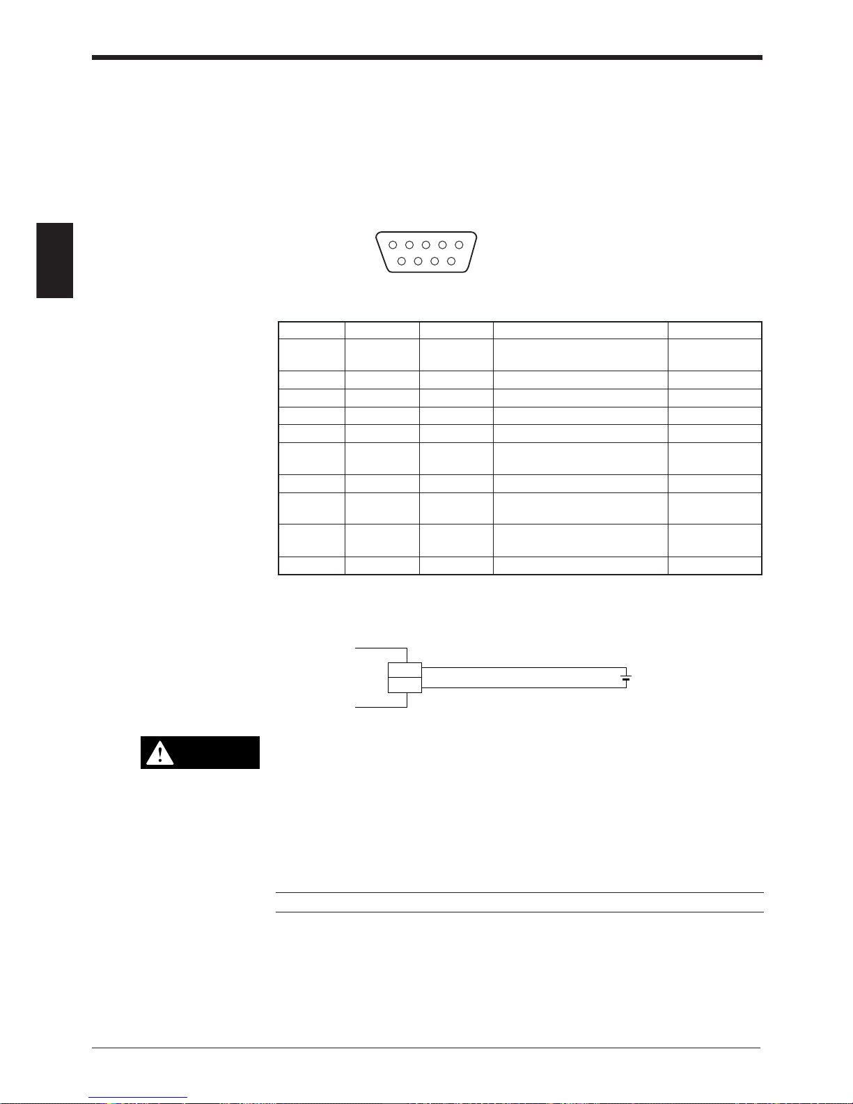
2.1.1 Connector pin assignment
The BL-700 connector has the following pin assignment.
D-sub 9-pin (female)
DTE specification (defined as terminal)
#4-40 screw (male)
12 3 45
6789
2.1.2 Power supply connections
• Be sure to match the polarities of the power supply when soldering the
connections. Reversing the polarities will damage the unit.
• Make sure that the power supply provides a stable 5 VDC ± 5%. If the
power supply does not function in the above range, it can damage the unit.
• Do not extend the power cable. A long power cable can cause a voltage
drop, preventing the BL-700 from starting properly.
Note: If the power supply is UL rated, it must provide Class 2 output.
Pin No. Cable color Symbol Description Signal direction
Connector Shield FG Frame ground —
case
1 Yellow TIM Trigger input Input
2 Brown RD (RXD) Receives RS-232C data Input
3 Purple SD (TXD) Sends RS-232C data Output
4 White OK OK output Output
5 Black GND (SG) Ground (common ground for —
respective signals)
6 Gray NG NG output Output
7 Pink RS (RTS) Request to send RS-232C data Output
(always ON)
8 Blue CS (CTS) Enable to send data through Input
RS-232C
9 Red +5 V +5 V DC power supply Input
5 VDC
BL-700
+5V
9
GND
5
+
CAUTION

Chapter 2 Connection and Installation
2
7
2.1.3 Wiring I/O
■ Trigger input
The trigger input is used to signal the BL-700 to start reading (start laser emission).
The trigger input is a non-voltage input (TTL input is also available with negative
logic).
■ OK/NG output
This output signals whether the readout data is the same as the preset data. When
no preset data has been entered, the signal indicates bar code read status. It is an
NPN open-collector output.
➮
See P. 44
2.1.4 RS-232C connection
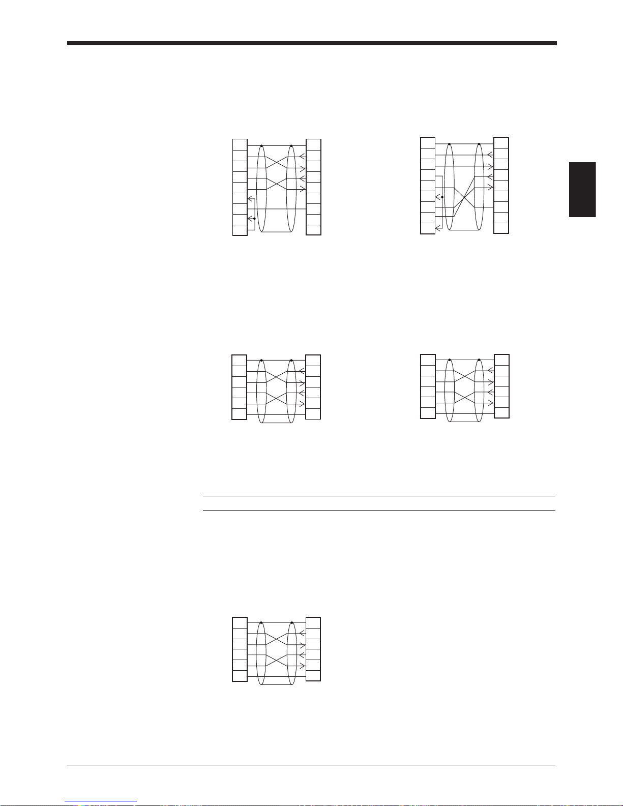
Wire the RS-232C as indicated below when connecting the BL-700 to a PC.
■ Connecting the computer with 25-pin
GND
TIM
1
5
5 VDC
10 kΩ
4.7
kΩ
Internal circuit
BL-700
Contact or
solid-state
3
2
8
7
5
9
BL-700
SD
CS
RS
GND
+5V
PC
2
3
4
7
6
5
20
SDRD
RD
RS
CS
SG
DR
ER
D-sub 25-pin (male)
M2.6 screw
D-sub 9-pin (male)
# 4-40 screw
GND
OK/NG
4/6
5
Load
BL-700
10 kΩ
* Rated load: 24 VDC
(30 mA) max.
+
Internal circuit

Chapter 2 Connection and Installation
2
8
2.2 Connecting BL-U1 and Wiring
Note: This product does not comply with EC directives.
To use the BL-U1 AC power supply, connect it as described below.
2.2.1 Connecting the power supply
Plug the BL-U1 power cable into an outlet.
Use a power supply with 100 to 240 VAC ± 10% (50/60 Hz).
2.2.2 Connecting the BL-700
Connect the BL-700 to the READER port of the BL-U1.
The BL-U1 READER port pin assignment is as described below.
■ BL-U1 READER port pin assignment
FG line
CAUTION
Pin No. Symbol Function Signal direction
1 TIM Trigger input Output
2 RD (RXD) Receives RS-232C data. Output
3 SD (TXD) Sends RS-232C data. Input
4OKOK Input
5 GND (SG) Ground (Common ground for respective —
signal)
6NGNG Input
7 RS (RTS) Ready to send RS-232C data. Input
8 CS (CTS) Request to send RS-232C data. Output
(Control method can be selected with the DIP
switches.)
➮
See p. 9.
9 +5 V +5 V power supply Output
D-sub 9-pin (male)
DCE specification (defined as terminal)
#4-40 screw (female)
12 3 45
6789
Note: Do not extend a power cable. A long power cable can cause a voltage drop,
preventing the BL-700 from starting properly.
Note: This product does not comply with EC directives.
Chapter 2 Connection and Installation
2
9
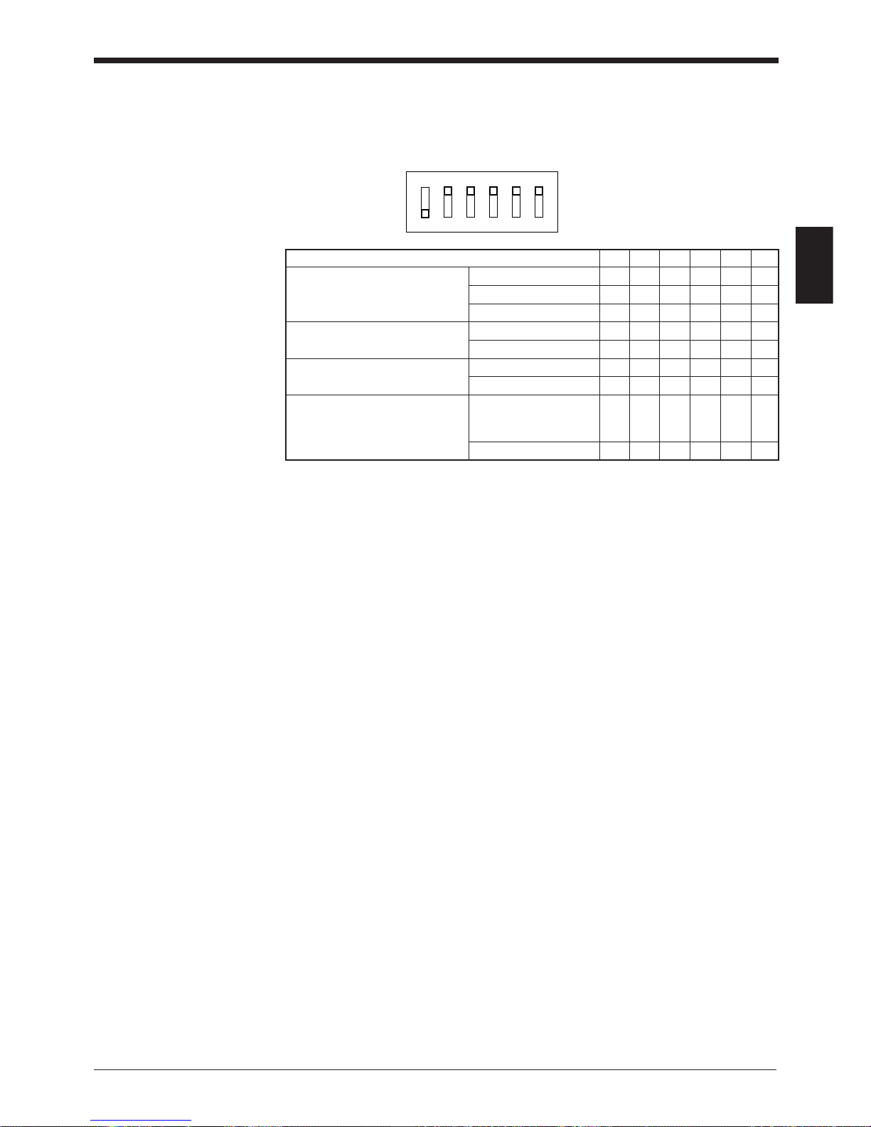
2.2.3 Setting BL-U1 DIP switches
Change the DIP switch settings depending on the selected interface and trigger
input method.
DIP Switch No. 1 2 3 4 5 6
Interface selection RS-232C ON OFF OFF
RS-422A OFF ON OFF
RS-485 multidrop OFF OFF ON
RS-422A terminator OFF OFF
(Termination resistance: 100 ) ON ON
RS-485 terminator OFF OFF
(Termination resistance: 100 ) ON ON
Selection of READER port ON or OFF according
CS control method to the RS-232C port OFF
CS signal status.
Normally ON ON
OFF
ON
123456
* The figure on the left shows the
default settings.
Chapter 2 Connection and Installation
2
10
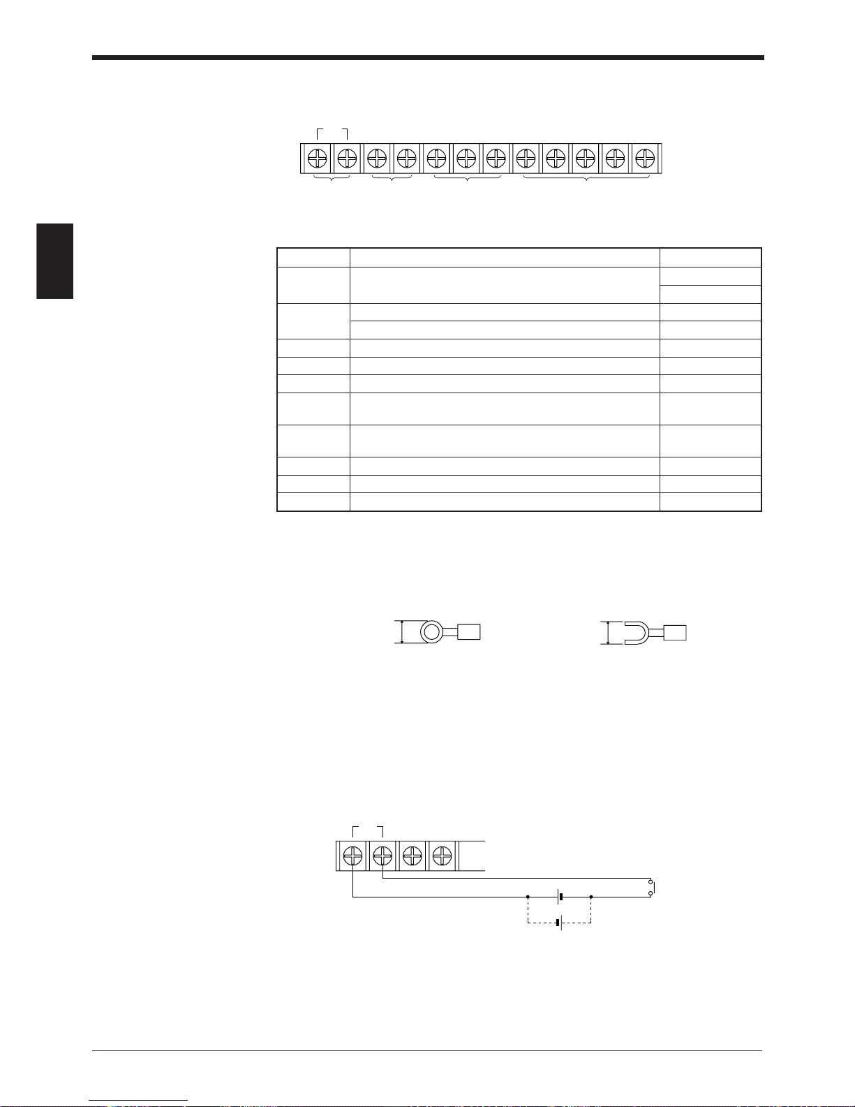
2.2.4 Terminals of I/O terminal block and wiring
* Viewed from the left of the terminal block
• M3.0 screws are used for the terminal block.
• Use the following crimp terminals for connections.
■ Connecting trigger input
The trigger input allows the BL-700 series to start reading bar codes (turn on the
laser beam).
The trigger input is turned ON when 8.5 to 30 VDC input is activated between the
trigger input terminals.
The BL-U1 power supply for the sensor can be used as the input power supply.
Symbol Description Signal direction
TIM Trigger input Input
Input
+12 V OUT- + terminal of power supply for sensor (12 VDC, 300 mA) Output
– terminal of power supply for sensor (0 V) Output
COM Common terminal for OK/NG output —
OK OK output Output
NG NG output Output
SDA + terminal for RS-422A data transmission/ Output,
RS-485 + terminal Input/Output
SDB – terminal for RS-422A data transmission/ Output,
RS-485 - terminal Input/Output
SG Signal ground —
RDA + terminal for RS-422A data reception Input
RDB – terminal for RS-422A data reception Input
TIM +12V OUT– COM OK NG SDA SDB SG RDA RDB
Trigger
input
Power supply
for sensors
(12 VDC, 300 mA)
OK/NG output RS-422A/RS-485
6.0 mm or
less
Round-shape
6.0 mm or
less
Fork-shape
TIM +12V OUT–
8.5 to 30 VDC
+
+
Contact or
solid-state
Chapter 2 Connection and Installation
2
11
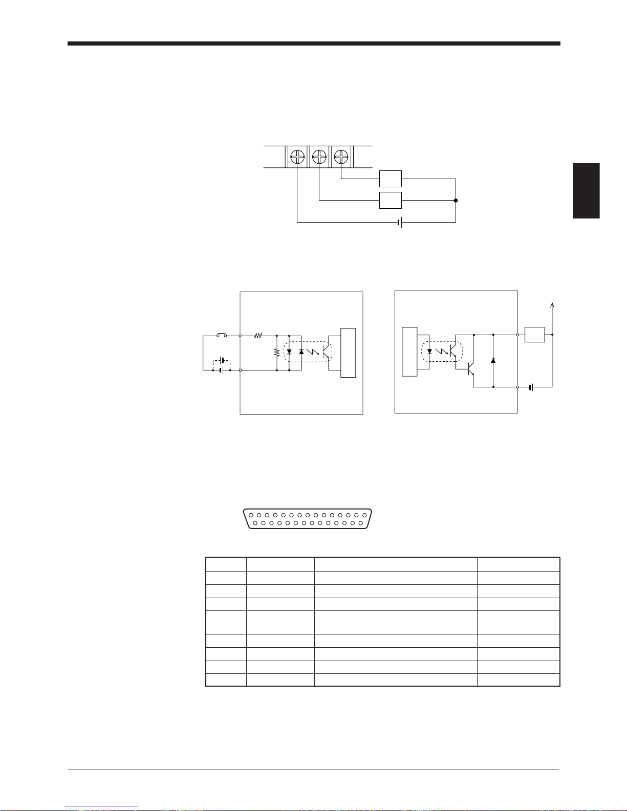
■ Connecting OK/NG output
The OK/NG output is used to differentiate between acceptable and unacceptable
results based on the comparison with the preset data, and to indicate whether or
not the BL-700 series successfully read bar codes.
➮
See P.44.
The OK/NG output is an open-collector output.
■ I/O circuit diagram
• Input circuit diagram • Output circuit diagram
2.2.5 Connecting RS-232C
Pin assignment
COM OK NG
Load
Load
+
*Rated load: 30 V max. (100 mA)
TIM
2.4
kΩ
3.3 kΩ
Internal circuit
Load
OK/NG
COM
+
Internal circuit
13 1
25 14
D-sub 25-pin (female)
DCE specification (defined as terminal)
M2.6 screw (female)
Pin No. Symbol Function Signal direction
1FG Frame ground —
2 SD (TXD) Sends RS-232C data Output
3 RD (RXD) Receives RS-232C data Input
4 RS (RTS) Ready to send RS-232C data Output
(always ON)
5 CS (CTS) Request to send RS-232C data Input
6 DR (DSR) Connected to pin No. 20 inside. Input
7 GND (SG) Signal ground —
20 ER (DTR) Connected to pin No. 6 inside. Output
Chapter 2 Connection and Installation
2
12
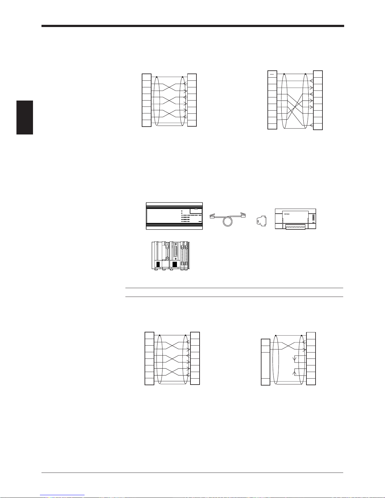
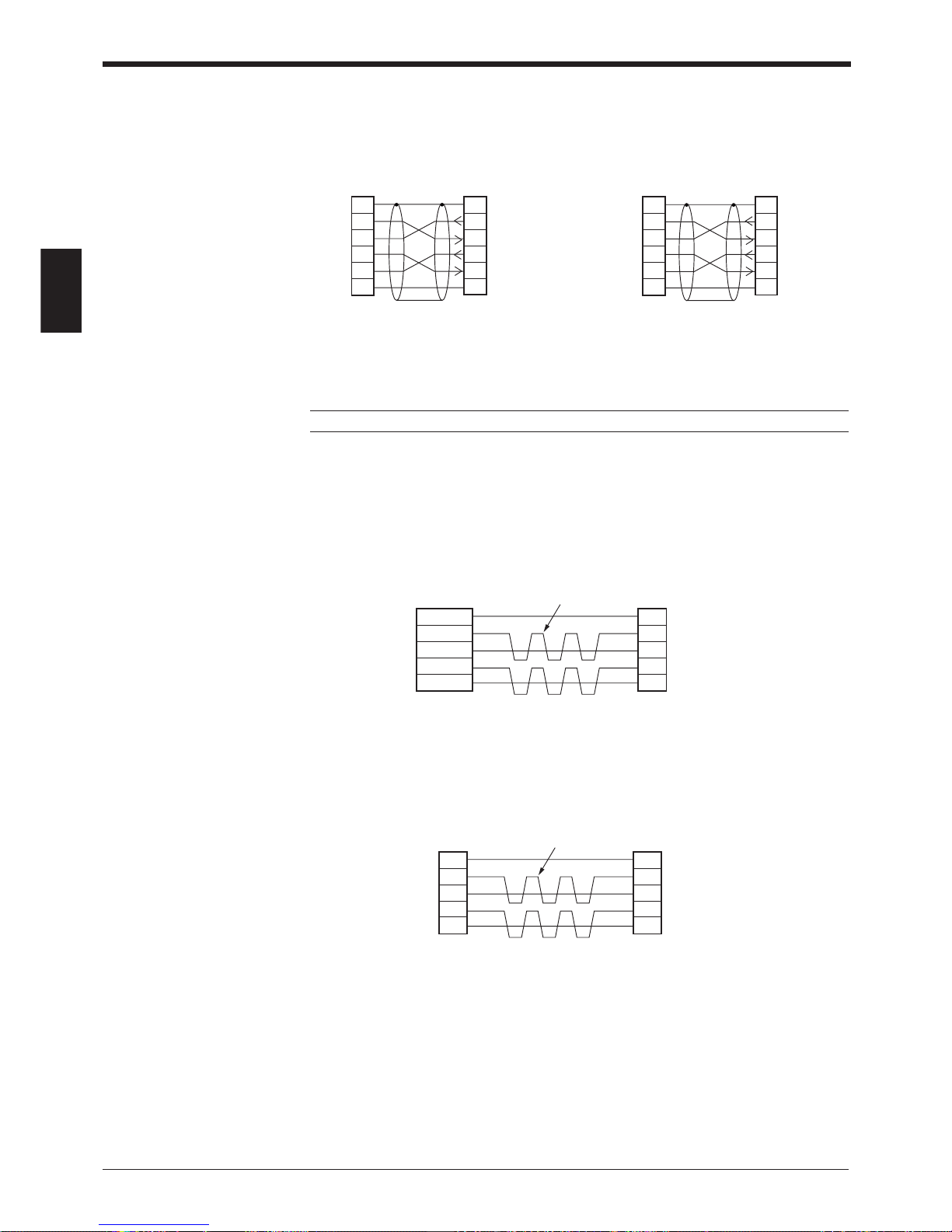
Wiring the RS-232C cable
■ Connecting a PC
25-pin serial port 9-pin serial port
■ Connecting KV series/Handheld programmer port
Use the optional cable manufactured by KEYENCE.
■ Connecting KV-L2*
Port 1 Port 2
2
PC
SD
RD
RS
CS
DR
ER
SG
3
4
5
6
2
11
BL-U1
SD
FGFG
RD
RS
CS
DR
ER
SG
3
4
5
6
20
7
20
7
D-sub 25-pin (male)
M2.6 screw
D-sub 25-pin (male)
M2.6 screw
* KEYENCE option OP-22149 (1.5 m)
or commercially available cross cable
can be used.
* KEYENCE option OP-22149 (1.5 m)
and OP-25057 (conversion connector) can be used.
2
PC
SD
CD
RD
RS
CS
DR
SG
ER
3
4
5
6
2
1
BL-U1
SD
FG
RD
SG
RS
CS
DR
ER
3
4
5
6
7
8
7
8
201
D-sub 25-pin (male)
M2.6 screw
Connector case
D-sub 9-pin (female)
#4-40 screw
OP-96369
BL-U1*
OP-96368 (2.5 m)
KV-10, 16, 24
KV-40, 80
KV-300*
2
KV-L2
SD
RD
RS
CS
DR
ER
SG
3
4
5
6
2
11
BL-U1*
SD
FGFG
RD
RS
CS
DR
ER
SG
3
4
5
6
20
7
20
7
D-sub 25-pin (male)
M2.6 screw
D-sub 25-pin (male)
M2.6 screw
3
KZ-L2
SD
RD
SG
5
2
1
BL-U1*
SD
FG
RD
RS
CS
DR
ER
SG
3
4
5
6
20
71
D-sub 25-pin (male)
M2.6 screw
Terminal block
* KEYENCE option OP-22149 (1.5 m) or
commercially available cross cable can be
used.
Note: KV-300 and BL-U1 are not available in Europe.
Chapter 2 Connection and Installation
2
13
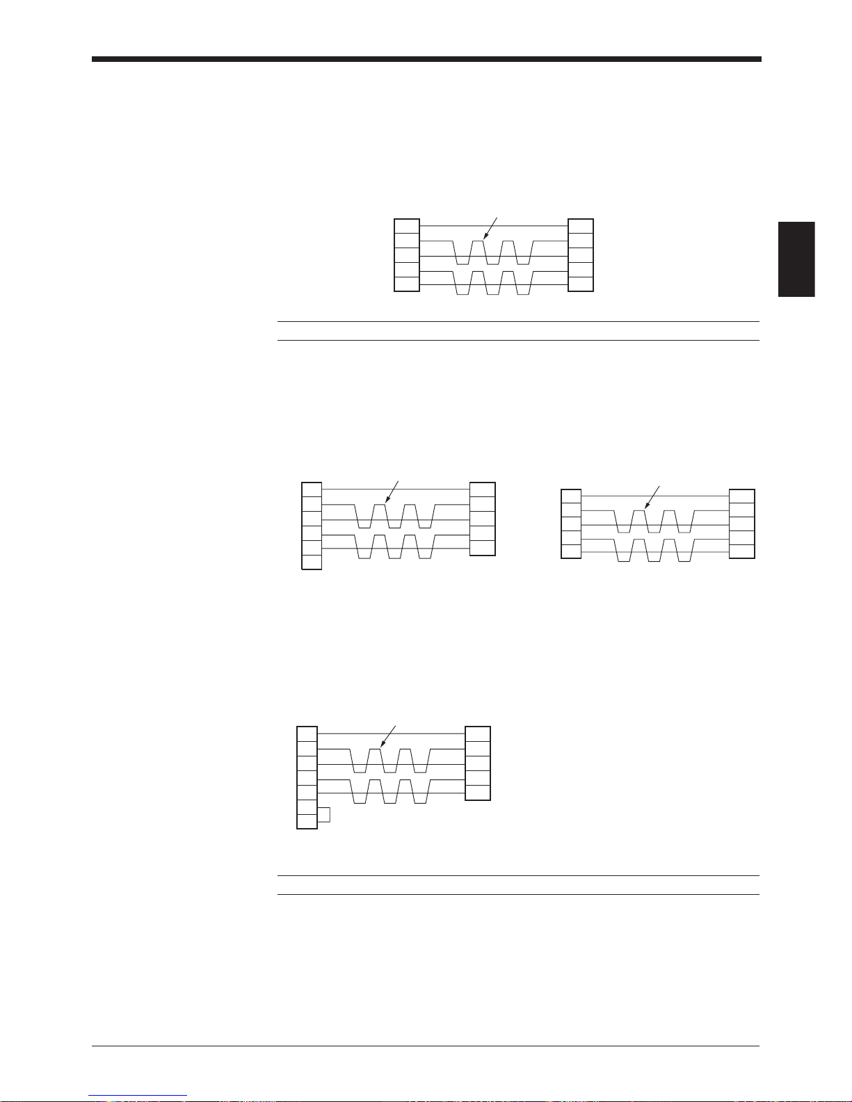
■ Connecting MELSEC-A series
Connection with AJ71C24,
AL71C24-S■■,
A0J2-C214-S1,
AJ71UC24
■ SYSMAC-C series
Connection with C-200H-LK201(-V1),
C-500-LK203,
C-500-LK201-V1,
C120-LK201-V1
Note: KV-L2 and BL-U1 are not available in Europe.
Connection with C-200HS(CPU21/23/31/33),
CQM1(CPU21/41/42/43/44),
C-200HE(CPU42),
C200HG(CPU43/63),
C200HX(CPU44/64),
C200HW-COM02/COM04/COM05/COM06
2
Link unit
SD
RD
RS
CS
DR
SG
ER
3
4
5
6
2
11
BL-U1*
SD
FGFG
RD
RS
CS
DR
SG
ER
3
4
5
6
7
20
7
20
CD
88
D-sub 25-pin (male)
M2.6 screw
D-sub 25-pin (male)
M2.6 screw
2
Link unit
RD
SD
ER
SG
DR
RS
CD
3
4
5
6
2
1–
BL-U1*
SD
FGConnector case
RD
RS
CS
DR
SG
ER
3
4
5
6
7
20
7
1
CS
88
D-sub 25-pin (male)
M2.6 screw
D-sub 9-pin (male)
M2.6 screw
Connection with A1SJ71(U)C24-R2/PRF,
A2CCPUC24,
A2CCPUC24-PRF
Connection with C-20H,
C-28H,
C-40H,
C-60H
* KEYENCE option OP-22149 (1.5 m) or
commercially available cross cable can be
used.
2
Link unit
SD
RD
RS
CS
SG
3
4
5
7
2
11
BL-U1*
SD
FGFG
RD
RS
CS
SG
3
4
5
7
D-sub 25-pin (male)
M2.6 screw
D-sub 25-pin (male)
M2.6 screw
2
PLC
SD
RD
RS
CS
SG
3
4
5
7
2
11
BL-U1*
SD
FGFG
RD
RS
CS
SG
3
4
5
7
D-sub 25-pin (male)
M2.6 screw
D-sub 9-pin (male)
M2.6 screw
2
PLC
SD
RD
RS
CS
SG
3
4
5
9
2
11
BL-U1*
SD
FGFG
RD
RS
CS
SG
3
4
5
7
D-sub 25-pin (male)
M2.6 screw
D-sub 9-pin (male)
M2.6 screw
Chapter 2 Connection and Installation
2
14
■ SYSMAC-CV series
Connection with CV500-LK201
(Port 1)
Note: BL-U1 is not available in Europe.
2.2.6 Wiring the RS-422A
Wire the RS-422A as indicated below.
■ Connecting a general RS-422A unit
Use the same wiring when connecting the BL-U1 to the BL-U1*.
• Turn ON the terminators (BL-U1/external unit terminal resistance: 100 ).
➮
See P.35
.
• The cable can be extended to within 1.2 km.
■ Connecting KV-L2*
Connecting the unit to RS-422A port 2
SDA
SG
BL-U1*
SDB
RDA
RDB
RD + (RDA)
SG
External unit
BL-U1*
RD – (RDB)
SD + (SDA)
SD – (SDB)
Twisted pair cable
SDA
SG
BL-U1*
SDB
RDA
RDB
RDB
SG
Link Unit
RDA
SDB
SDA
Twisted pair cable
Connection with CV500-LK201 (Port 2),
CV500,
CV1000,
CVM1
* KEYENCE option OP-22149 (1.5 m) or
commercially available cross cable can be
used.
2
Link unit
SD
RD
RS
CS
SG
3
4
5
7
2
11
BL-U1*
SD
FGFG
RD
RS
CS
SG
3
4
5
7
D-sub 25-pin (male)
M2.6 screw
D-sub 25-pin (male)
M2.6 screw
2
PLC
SD
RD
RS
CS
SG
3
4
5
9
2
11
BL-U1*
SD
FGFG
RD
RS
CS
SG
3
4
5
7
D-sub 25-pin (male)
M2.6 screw
D-sub 9-pin (male)
M2.6 screw
Chapter 2 Connection and Installation
2
15
■ Connecting the MELSEC-A series
Connecting with AJ71C24,
AJ71C24-S■■,
AJ71UC24,
A0J2-C214-S1,
A1SJ71(U)C24-R4
Note: BL-U1 and KV-L2 are not available in Europe.
■ Connecting SYSMAC-C series
Connecting with C200H-LK202 (-V1), Connecting with C200HW-COM03/
C500-LK201-V1, COM06
C500-LK203,
C120-LK202-V1
■ Connecting SYSMAC-CV series
Connecting with CV-500-LK201,
CV500,
CV1000,
CVM1
Note: BL-U1 is not available in Europe.
SDA
SG
BL-U1*
SDB
RDA
RDB
RDA
SG
Link unit
RDB
SDA
SDB
Twisted pair cable
SDA
SG
BL-U1*
SDB
RDA
RDB
Link unit
1RDB
RDA
SDB
SDA
FG
6
5
9
7
3
SG
D-sub 9-pin (male)
M2.6 screw
Twisted pair cable
SDA
SG
BL-U1*
SDB
RDA
RDB
8RDB
RDA
SDB
SDA
6
2
1
9
SG
D-sub 9-pin (male)
M2.6 screw
Twisted pair cable
Communication
board
SDA
SG
BL-U1*
SDB
RDA
RDB
PLC
8RDB
RDA
SDB
SDA
RS
CS
6
2
1
4
9
SG
5
D-sub 9-pin (male)
M2.6 screw
Twisted pair cable
Chapter 2 Connection and Installation
2
16
24 VDC
+
+–
24V DC IN
24 VDC
+
+–
24V DC IN
N.C. N.C. N.C.
CAUTION
D-sub 9-pin (male)
DCE specification (defined as terminal)
#4-40 screw (female)
12 3 45
6789
POWER SD RD
READER
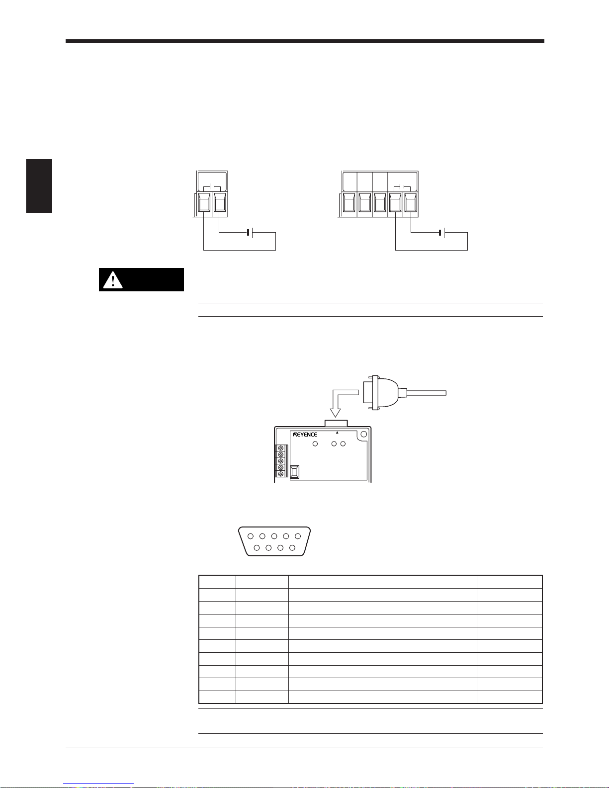
2.3 Wiring the KEYENCE Power Supply Unit BL-U2/N-42
To use the BL-U2/N-42, connect as indicated below.
2.3.1 Connecting the power supply
Connect BL-U2/N-42 to a 24 VDC power supply.
BL-U2 N-42
Make sure that the power supply provides 24 VDC. If the power supply output
is not 24 VDC, it can damage the unit.
Note: If the power supply is UL rated, it must provide Class 2 output.
2.3.2 Connecting the BL-700 to BL-U2/N-42
Connect the BL-700 to the READER port of the BL-U2/N-42.
■ READER port pin assignment
Note: Do not extend a power cable. A long power cable can cause a voltage drop,
preventing the BL-700 from starting properly.
Pin No. Symbol Function Signal direction
1 TIM Trigger input Output
2 RD (RXD) Receives RS-232C data Output
3 SD (TXD) Sends RS-232C data Input
4OK OK signal Input
5 GND (SG) Ground (Common ground for respective signal) —
6NG NG signal Input
7 RS (RTS) Ready to send RS-232C data Input
8 CS (CTS) Request to send RS-232C data Output
9 +5 V 5 V power supply output Output
 Loading...