

Kenwood TK-860GN, TK-862GN, TK-862G Service Manual
UHF FM TRANSCEIVER
TK-860G/
(
N)/862G/
SERVICE MANUAL
5 TONE
REVISED
TK-860G/(N)
Panel assy
(A62-0642-03)
(
)
N
Cabinet (Upper)
(A01-2165-13)
© 2003-2 PRINTED IN JAPAN
B51-8563-10 (N) ***
TK-862G/(N)
Panel assy
(A62-0731-03)
Key top
(K29-5343-02)
Key top
(K29-5344-02)

TK -860/G(N)/862G/(N
CONTENTS / GENERAL
)
CONTENTS
GENERAL ................................................................. 2
SYSTEM SET-UP ..................................................... 4
OPERATING FEATURES ......................................... 5
REALIGNMENT...................................................... 11
INSTALLATION...................................................... 18
CIRCUIT DESCRIPTION ......................................... 24
SEMICONDUCTOR DATA..................................... 29
DESCRIPTION OF COMPONENTS ....................... 31
PARTS LIST ............................................................ 33
EXPLODED VIEW .................................................. 42
PACKING ................................................................ 44
ADJUSTMENT ....................................................... 45
PC BOARD VIEWS
DISPLAY UNIT (X54-3270-10) : TK-860G ........ 54
DISPLAY UNIT (X54-3280-10) : TK-862G ........ 55
PLL/VCO (X58-4670-15) ................................... 56
TX-RX UNIT (X57-596X-XX) (A/2) ................... 57
TX-RX UNIT (X57-596X-XX) (B/2) ................... 63
SCHEMATIC DIAGRAM ........................................ 67
BLOCK DIAGRAM.................................................. 75
LEVEL DIAGRAM ................................................... 78
TERMINAL FUNCTION ......................................... 80
SPECIFICATIONS................................................... 81
GENERAL
INTRODUCTION
SCOPE OF THIS MANUAL
This manual is intended for use by experienced technicians familiar with similar types of commercial grade communications equipment. It contains all required service information for the equipment and is current as of the publication date. Changes which may occur after publication are
covered by either Service Bulletins or Manual Revisions.
These are issued as required.
ORDERING REPLACEMENT PARTS
When ordering replacement parts or equipment information, the full part identification number should be included.
This applies to all parts : components, kits, or chassis. If the
part number is not known, include the chassis or kit number
of which it is a part, and a sufficient description of the required component for proper identification.
PERSONNEL SAFETY
The following precautions are recommended for personnel safety :
• DO NOT transmit if someone is within two feet (0.6
meter) of the antenna.
• DO NOT transmit until all RF connectors are verified se-
cure and any open connectors are properly terminated.
• SHUT OFF and DO NOT operate this equipment near
electrical blasting caps or in an explosive atmosphere.
• All equipment should be properly grounded before
power-up for safe operation.
• This equipment should be serviced by a qualified techni-
cian only.
Note
The terms, “Wide” and “Semi wide” this service
manual, are same as “W5k” and “W4k” in the KPG-67D
(Field Programming Unit) menu and help text, respectively.
PRE-INSTALLATION CONSIDERNATIONS
1. UNPACKING
Unpack the radio from its shipping container and check
for accessory items. If any item is missing, please contact
KENWOOD immediately.
2
GENERAL
TK-860G /(N)/862G/(N
)
2. PRE-INSTALLATION CHECKOUT
2-1. Introduction
Each radio is adjusted and tested before shipment. However, it is recommended that receiver and transmitter operation be checked for proper operation before installation.
2-2. Testing
The radio should be tested complete with all cabling and
accessories as they will be connected in the final installation. Transmitter frequency, deviation, and power output
should be checked, as should receiver sensitivity, squelch
operation, and audio output. Signalling equipment operation
should be verified.
3. PLANNING THE INSTALLATION
3-1. General
Inspect the vehicle and determine how and where the
radio antenna and accessories will be mounted.
Plan cable runs for protection against pinching or crushing wiring, and radio installation to prevent overheating.
3-2. Antenna
The favored location for an antenna is in the center of a
large, flat conductive area, usually at the roof center. The
trunk lid is preferred, bond the trunk lid and vehicle chassis
using ground straps to ensure the lid is at chassis ground.
3-3. Radio
The universal mount bracket allows the radio to be
mounted in a variety of ways. Be sure the mounting surface
is adequate to support the radio’s weight. Allow sufficient
space around the radio for air cooling. Position the radio
close enough to the vehicle operator to permit easy access
to the controls when driving.
3-4. DC Power and wiring
1. This radio may be installed in negative ground electrical
systems only. Reverse polarity will cause the cable fuse
to blow. Check the vehicle ground polarity before installa-
tion to prevent wasted time and effort.
2. Connect the positive power lead directly to the vehicle
battery positive terminal. Connecting the Positive lead to
any other positive voltage source in the vehicle is not rec-
ommended.
3. Connect the ground lead directly to the battery negative
terminal.
4. The cable provided with the radio is sufficient to handle
the maximum radio current demand. If the cable must be
extended, be sure the additional wire is sufficient for the
current to be carried and length of the added lead.
4. INSTALLATION PLANNING – CONTROL STATIONS
4-1. Antenna system
Control station. The antenna system selection depends
on many factors and is beyond the scope of this manual.
Your KENWOOD dealer can help you select an antenna system that will best serve your particular needs.
4-2. Radio location
Select a convenient location for your control station radio
which is as close as practical to the antenna cable entry
point. Secondly, use your system’s power supply (which
supplies the voltage and current required for your system).
Make sure sufficient air can flow around the radio and power
supply to allow adequate cooling.
SERVICE
This radio is designed for easy servicing. Refer to the
schematic diagrams, printed circuit board views, and alignment procedures contained in this manual.
Note
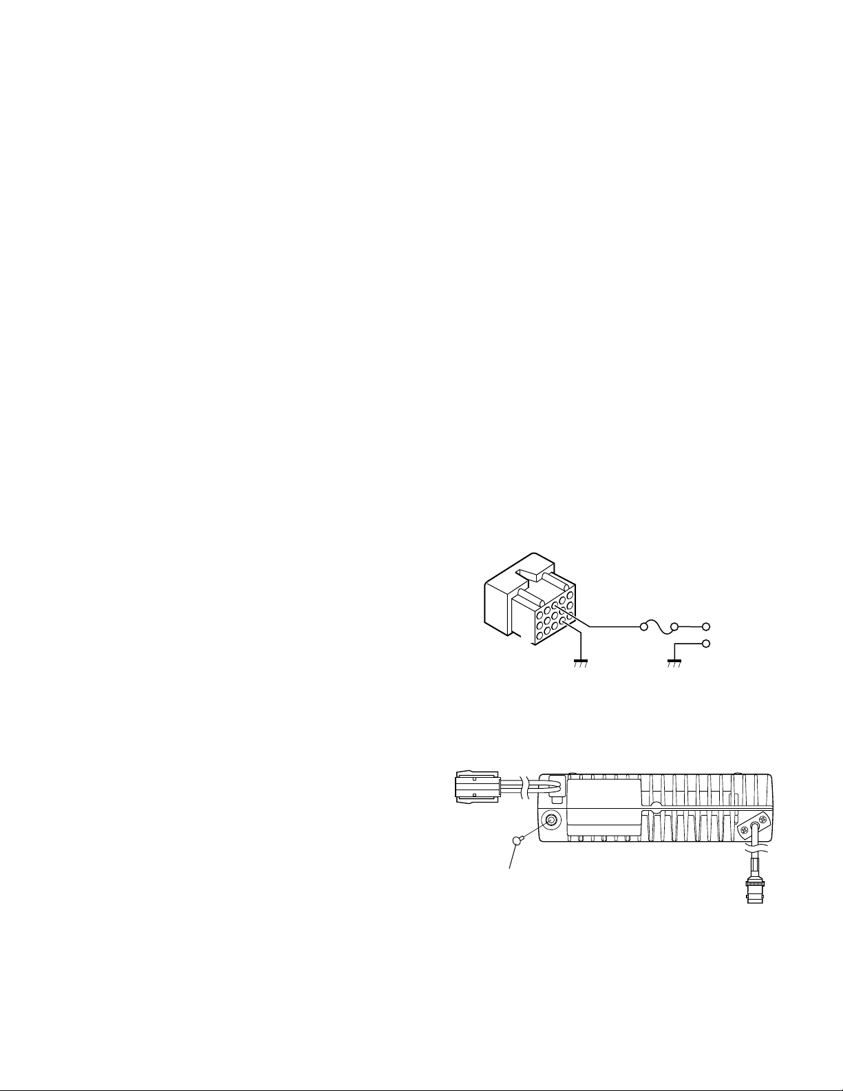
When you modify your radio as described in system setup, take the following precaution.
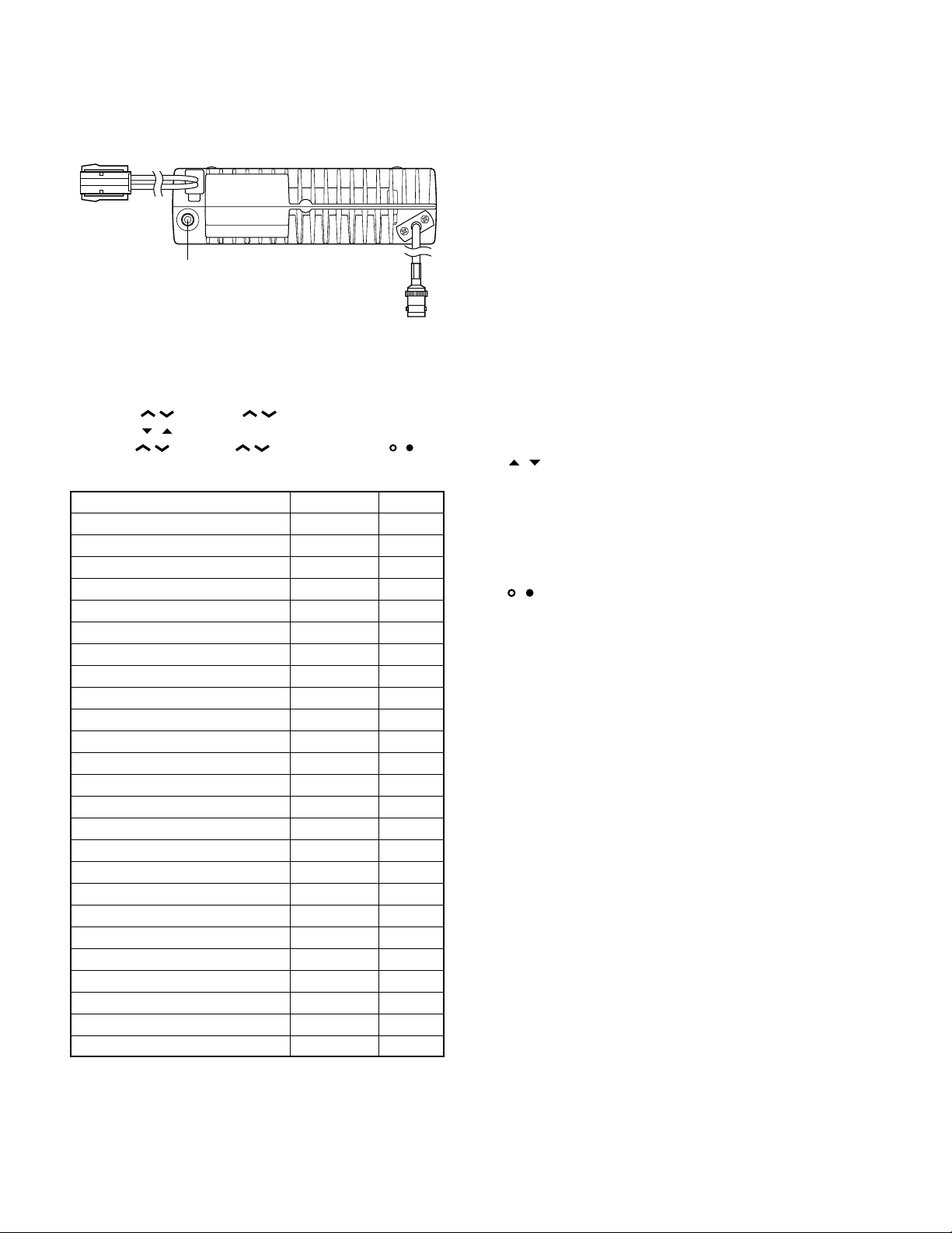
The rating of pin 7 (SB) of the accessory connector cable
(KCT-19) on the rear of the radio is 13.2V (1A). Insert a 1A
fuse if you use the SB pin for external equipment.
Accessory connector
cable (KCT-19)
1
7
13
15
If you do not intend to use the 3.5-mm jack for the external speaker, fit the supplied speaker-jack cap (B09-0235-05)
to stop dust and sand getting in.
Speaker-jack cap
(B09-0235-05)
3
6
+
–
3
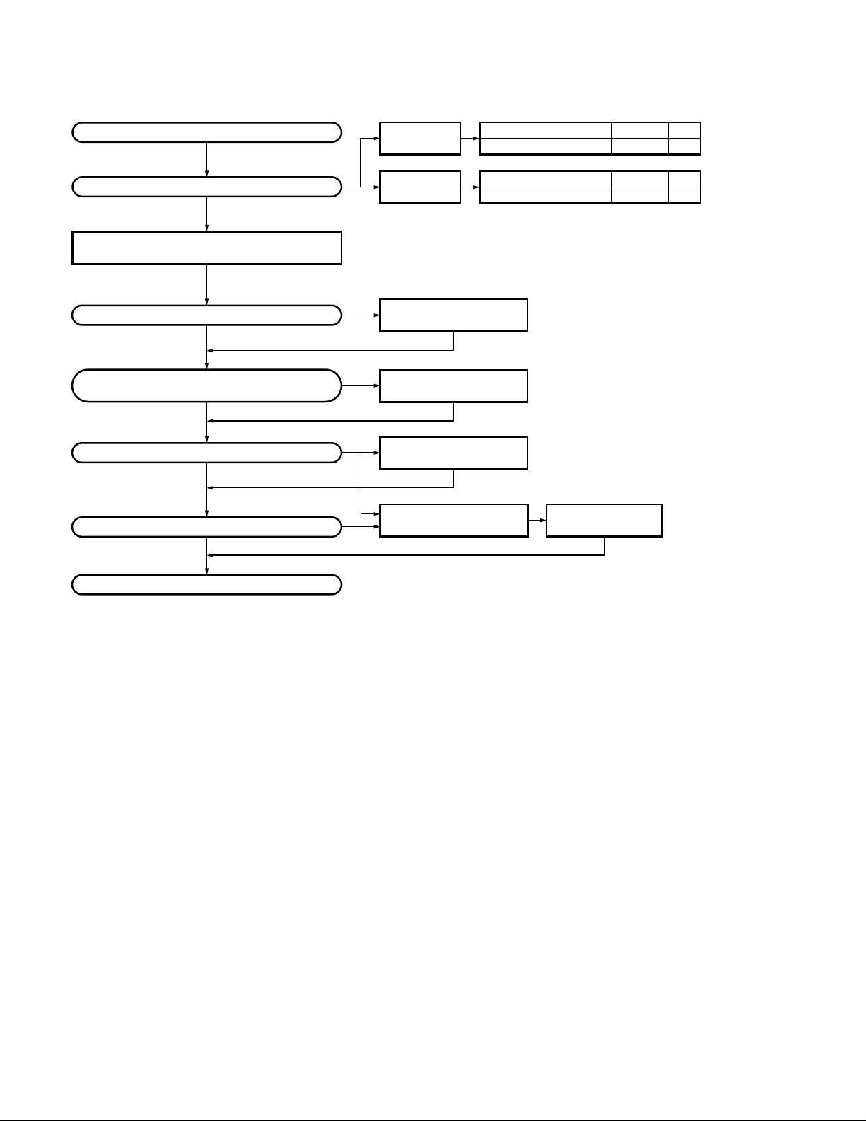
TK -860/G(N)/862G/(N
SYSTEM SET-UP
)
Merchandise received
Choose the type of transceiver
Transceiver programming (Option)
Are you using the public address?
NO
Are you using the KGP-1A Modem GPS receiver
or the KGP-1B Modem GPS controller?
NO
Are you using the external speaker?
NO
Are you using ignition sense cable?
NO
128ch models
TK-860G
8ch models
TK-862G
See page 12.
A personal computer (IBM PC or compatible), programming interface (KPG-22),
and programming software (KPG-67D) are required for programming.
(The frequency and signalling (option) data are programmed for the transceiver.)
YES
YES
YES
*
KAP-1
PA/HA unit
KCT-20
Connection cable
KES-3
External speaker
*
Accessory connector cable
YES
KCT-19
Frequency range (MHz)
440~470
Frequency range (MHz)
440~470
See page 23.
Installation the TX-RX unit when used KAP-1.
(Option)
See the KCT-20 instruction manual
(B62-0733-11).
(Option)
See page 26.
(Option)
See page 21.
Ignition sense cable
(Option) (Option)
RF power
25W
RF power
25W
See page 22.
KCT-18
Type
E,NE
Type
E,NE
Delivery
: You can install either KCT-19 or KCT-20 to the
*
TK-860G/862G transceiver
4
TK-860G /(N)/862G/(N
OPERATING FEATURES
)
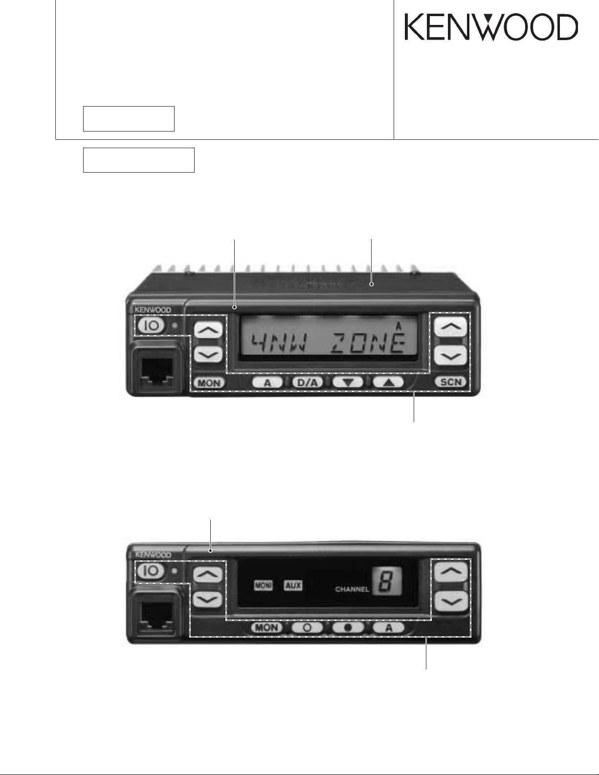
1. Controls and Functions
1-1. TK-860G Front Panel
1 2 3 4 5
76
1-2. TK-862G Front Panel
1 2 3 4 5
76
1-3. Speaker/Microphone
■ Optional KMC-30
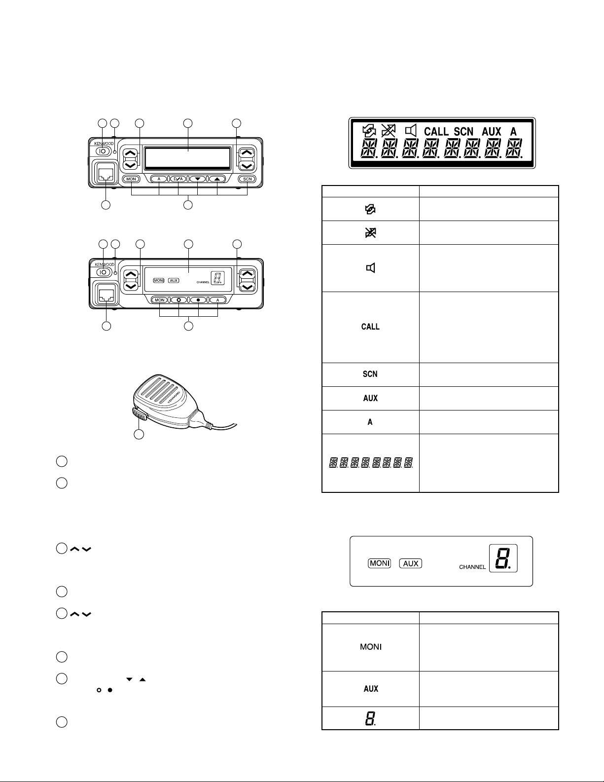
1-4. Display
■ TK-860G
Indicator Description
Not used in this transceiver.
Appears when the selected channel
in busy.
Appears when QT, DQT, DTMF,
2-Tone, or 5-tone decoding is
deactivated (by pressing the
Monitor or Squelch key).
If programmed by your dealer,
appears when you receive a Code
Squelch, Selective Call, 2-Tone code,
5-Tone code.
transmit
Selective Call.
Appears while scanning.
Also appears when you
using Code Squelch or
8
1
IO (Power) switch
Press to switch the transceiver ON (or OFF).
2
LED indicator
Lights red while transmitting. Lights green while receiving. If programmed by the dealer, flashes orange while
receiving a Code Squelch or Selective Call code, or a 2Tone code that matches the one set up in your transceiver.
/ keys
3
These are PF (Programmable Function) keys. Press each
key to activate its auxiliary function. The default settings
are Volume Up and Volume Down.
4
Display
See right.
5
/ keys
These are PF (Programmable Function) keys. Press each
key to activate its auxiliary function. The default settings
are Channel Up and Channel Down.
Microphone jack
6
Insert the microphone plug into this connector.
MON, A, D/A,
7
MON,
These are PF (Programmable Function) keys. Press each
key to activate its auxiliary function.
PTT (Push-to-Talk) switch
8
Press this switch, then speak into the microphone to call
a station.
, , and A keys (TK-862G)
, , and SCN keys (TK-860G)
Appears when the AUX port is
activated.
Appears when the selected channel
is included in the scanning sequence.
Displays the selected channel
number (or name), DTMF digits
(when entering digits, confirming
digits, or making a call), and mes-
sages received via Selective Call.
■ TK-862G
Indicator Description
Appears when QT, DQT, DTMF,
2-Tone, or 5-Tone decoding is
deactivated (by pressing the
Monitor or Squelch key).
Appears when the AUX port is
activated. Flashes orange when the
Talk-Around feature is active.
Displays the selected channel
number.
5
TK -860/G(N)/862G/(N
OPERATING FEATURES
)
1-5. Rear panel
Power input
connector
External
speaker jack
Antenna
connector
1-6. Programmable Auxiliary Functions
The following keys can be programmed with the functions listed below.
TK-860G :
TK-862G :
AUX Yes Yes
Call 1 No Yes
Call 2 No Yes
Channel Down Yes Yes
Channel Up Yes Yes
Display Character (TK-860G only) Yes Yes
Group Down Yes Yes
Group Up Yes Yes
Home Channel Yes Yes
Horn Alert YeS Yes
Key Lock Yes Yes
Monitor Yes Yes
Monitor Momentary Yes Yes
None (No function) Yes Yes
Public Address Yes Yes
Redial Yes No
Scan (TK-860G only) Yes Yes
Scan Del/Add (TK-860G only) Yes Yes
Selcall Entry No Yes
Squelch Momentary Yes Yes
Squelch Off Yes Yes
Talk-Around Yes Yes
Volume Up Yes Yes
Volume Down Yes Yes
2-Tone Encode* Yes No
* : The code for the TK-862G transceiver is not selectable. You
can transmit only one 2-Tone code, which is pre-programmed in
the transceiver.
The Emergency function can also be programmed. However, it
can only be used with a foot switch.
/ (left side), / (right side), MON, A, D/A,
, , and SCN.
/ (left side), / (right side), MON, , , and
A.
Function DTMF/2-Tone 5-Tone
2. Operation Features
The TK-860G/862G is a UHF FM radio designed to operate in conventional format. The programmable features are
summarized.
3. Transceiver Controls and Indicators
3-1. Front Panel Controls
All the keys on the front panel are momentary-type push
buttons. The functions of these keys are explained below.
• POWER key
Transceiver POWER key. When the power is switched
off, all the parameters are stored in memory. When the
power is switched on again, the transceiver returns to the
previous conditions.
• CHANNEL UP/DOWN key (Programmable)
• / key (Programmable) : TK-860G only
• SCAN key (Programmable) : TK-860G only
• MONITOR key (Programmable)
• A, D/A key (Programmable) : TK-860G only
• , , A key (Programmable) : TK-862G only
• VOLUME UP/DOWN key (Programmable)
• BUSY/TX LED
The BUSY indicator (Green LED) shows that the channel
is in use. The TX indicator (Red LED) shows that you are
transmitting.
3-2. Programmable Keys
The FPU (KPG-67D) enables programmable keys to select the following functions.
AUX, Channel down, Channel up, Display character *
Emergency (Only foot key), Group down *
Home channel, Horn alert, Key lock, Squelch Momentary,
Squelch Off, Monitor Momentary, Monitor, Public address,
Redial, Scan *
Volume up, 2-tone encode and None.
These functions the FPU programs to the function keys
and described in the following sections.
*1 : TK-860G only.
1
, Scan del/add *1, Talk around, Volume down,
• AUX
If this key is pressed, “AUX” icon lights on the display
and AUX port which is inside of the transceiver turns to the
high level. If pressed again, the “AUX” icon goes off and
the AUX ports turns to the lower level.
• Channel up/down
When the key is pressed each time, the channel number
to be selected is incremented/decremented and repeats if
held for one second or longer.
1
, Group up *1,
1
,
6
OPERATING FEATURES
• Display character (TK-860G only)
This key switches the LCD display between the group
and channel number and the group and channel name.
• Emergency
Pressing this key for longer than 1 second causes the
transceiver to enter the emergency mode. The transceiver
jumps to the programmed “Emergency the group and channel” and transmits for 25 seconds.
The transceiver disables mic mute while transmitting.
After finishing transmission, the transceiver receivers for 5
seconds. The transceiver mutes the speaker while receiving. Following the above sequence, the transceiver continues to transmit and receive.
• Emergency mode system chart (TK-860G)
Foot switch 1 push (Hold it down for about one second.)
Emergency mode
Emergency channel LCD dots light
TK-860G /(N)/862G/(N
*1
)
TX 25 sec. ←→ RX 5 sec.
or
*2
Foot switch 1 push
After 1 min.
Horn/Light operation
[D/A] key 1 push
Horn/Light operation stop
Emergency ACK code receive
Emergency reset code receive [MON] key + Foot SW 1 push
Emergency mode reset
Normal operation
• Emergency mode system chart (TK-862G)
Foot switch 1 push (Hold it down for about one second.)
Emergency mode
Emergency channel LCD dot status change
TX 25 sec. ←→ RX 5 sec.
or
*2
Foot switch 1 push
After 1 min.
Horn/Light operation
Emergency ACK code receive
Emergency reset code receive [MON] key + Foot SW 1 push
*3
LCD dots light
or
*1 : 3 left most dots light.
*2 : Hold the foot switch again for about one second.
*3 : 2 right most dots light.
LCD dot status change
or
Dots
*2
*1
Dot
*1
*2
Dots
Dot
[D/A] key 1 push
Horn/Light operation stop
Emergency mode reset
Normal operation
*1 : When the dot indicator is on, it turns off.
When the dot indicator is off, it turns on.
*2 : Hold the foot switch again for about one second.
7

TK -860/G(N)/862G/(N
OPERATING FEA TURES
)
• Group up/down (TK-860G only)
When the key is pressed each time, the group number to
be selected is incremented/decremented and repeats if held
for one second or longer.
•Home channel
Press this key once, the channel switches to the pre-pro-
grammed home channel.
• Horn alert
If you are called from the base station using 2-tone/DTMF
while you are away from your transceiver, you will be
alerted by the vehicle horn or some other type of external
alert. To turn the horn alert function on , press this key. A
confirmation tone sounds, (and the display shows “HA” on
the LCD *
turned off.
1
).
If this key is pressed again, the horn alert function is
*1 : TK-860G only.
• Key lock
Pressing this key causes the transceiver to accept entry
of only the [Vol Up/Down], [Key lock], [PTT], [Monitor A],
[Monitor B], [Monitor C], [Monitor D], and [Emergency] keys.
• Monitor
Used to release signalling or squelch when operating as a
conventional. It is also used to reset option signalling.
• Public address
Public address amplifies the microphone audio, and out-
puts it through a PA speaker. PA is activated by pressing
this key. A confirmation tone sounds, (and the display
shows “PA” *
or non-scanning).
If this key is pressed again, a confirmation tone will
sound, (the display will return to the normal channel or
SCAN display *
*1 : TK-860G only.
1
). PA can be activated at anytime (scanning
1
), and the PA function will turn off.
• Redial
If you press this key when the group/channel is dis-
played, the last transmitted DTMF code will appear on the
display. Pressing the PTT switch at this time will transmit
the displayed DTMF code.
• Scan (TK-860G only)
Press this key starts scanning. Pressing this key stops
scanning.
• Scan del/add (TK-860G only)
This key switches the currently displayed channel be-
tween “Delete” and “Add”.
The “Add” channel contained in the scan sequence, and
“Delete” channel is not contained. In the scan mode, this
key switches the channnel delete or add temporarily.
• Talk around
Press this key, the transceiver uses the receive fre-
quency and the tone for transmission.
The operator can call the other party directory (without
repeater). Press this key again, the talk around function
goes off.
• Volume up/down
When the key is pressed, the volume level is increased/
decreased and repeats if held for 200ms or longer.
• None
Sounds error operation beep, and no action will occur.
Use this function when the transceiver is required to be
more simple operated.
• Call 1 or 2 (5-Tone)
Press the [CALL #] key to transmit the 5-tone code that is
programmed to “Call #” in the channel data.
• Selcall entry
Press [Selcall entry] key to enter the desired Selcall code
you want to call.
When you enter Selcall entry mode, the “TX address”
number appears on the LCD.
To enter Selcall number, use the keypad. You can also
use the channel selector to select the number.
4. Scan Operating (TK-860G only)
■ Scan types
• Single group scan
You can scan all valid (ADD) channels in the displayed
group that can be selected with the group up/down key.
• Multiple group scan
You can scan all valid (ADD) channels in the all valid
(ADD) group.
■ SCAN start condition
One or more non-priority channels must be added to all
channels that can be scanned. The transceiver must be in
normal receive mode (PTT off).
When you activate the key programmed to the scan function, the scan starts. The scan icon “SCN” lights and
“SCAN” is indicated on alphanumeric display.
■ Scan stop condition
The scan stops temporarily if the following conditions are
satisfied.
1) A carrier is detected, then signalling matches on chan-
nels for which receive the signalling is set by the pro-
gramming software.
2) A carrier is detected on the channels for which receiving
signalling is not set by the programming software or
when the monitor (signalling cancel) function is activated.
8

TK-860G /(N)/862G/(N
OPERATING FEATURES
)
■ Scan channel types
1) Priority channel is the most important channel for the
scan, and always detects a signal during scan and when
the scan stops temporarily.
2) Non-priority channels detects a signal during scan. For
the channels that can be selected with the group or channel up/down key when the scan does not occur, adds an
indicator “A” lights.
■ Priority channel setting
A priority channel can be set as follows with the program-
ming software (KPG-67D).
1) Specify a priority channel as a fixed priority channel.
2) Make a selected channel, a priority channel.
■ Scan type according to the priority channel
1) When no priority channel is set : Only the non-priority
channels are scanned.
If a non-priority channel stops temporarily, it stops until
there is no signal on the channel.
2) When priority channel is set : Either priority channel is
scanned.
If a non-priority channel stops temporarily, a priority channel signal is detected at certain intervals.
If a priority channel stops temporarily, it stops until there
is no signal on the priority channel.
■ Revert channel
The revert channel is used to transmit during scanning
and set by the programming software (KPG-67D).
1) Priority
The transceiver reverts to the priority channel.
2) Priority with talkback
The transceiver reverts to the priority channel.
If you press PTT during a resume timer (dropout delay
time, TX dwell time) or calling, you can transmit on current channel to answer to the call however revert channel
is set to priority channel.
After resume time, scan re-starts and transmission channel is return to priority channel.
3) Selected channel
The transceiver reverts to the channel before scanning or
the channel that you changed during scan.
4) Last called channel
The transceiver reverts to the last called channel during
the scan.
5) Last used channel
The transceiver reverts to the last used (transmitted)
channel during scan. “Last used” revert channel includes talkback function.
6) Selected with talkback
The transceiver reverts to the channel before scanning or
the channel that you changed during scan.
■ Scan end
When you reactivate the key programmed to the scan
function during scan mode, the scan ends.
The scan icon “SCN” and “SCAN” display goes off.
■ Temporarily delete/add
It is possible to delete or add channel temporarily during
scan. When scan stops on unnecessary channel for example by interference of the other party, activate the delete/
add function (for example press the key), then that channel
is deleted temporarily and scan re-start immediately.
When you would like to add the deleted channel temporarily to scan sequence, select the desired (deleted) channel
during scan, activate the delete/add function (for example
press the key) before scan re-start.
That channel is added temporarily to scan sequence. The
temporary deleted or added channels are returns to pre-set
delete/add, when the transceiver exits from scan mode.
5. Details of Features
■ Time-out timer
The time-out timer can be programmed in 15 seconds
increments from 15 seconds to ten minutes. If the transmitter is keyed continuously for longer than the programmed
time, the transmitter is disabled and a warning tone sounds
while the PTT button is held down. The alert tone stops
when the PTT button is released.
■ PTT ID
PTT ID provides a DTMF ANI to be sent with every time
PTT (beginning of transmission, end of transmission, or
both).
You can program PTT ID “on” or “off” for each group.
The contents of ID are programmed for each channel.
The timing that the transceiver sends ID is programmable.
BOT : DTMF ID (BOT) is sent on beginning of transmis-
sion.
EOT : DTMF ID (EOT) is sent on end of transmission.
Both : DTMF ID (BOT) is sent on beginning of transmis-
sion and DTMF ID (EOT) is sent on end of transmission.
■ Radio password (TK-860G only)
When the password is set in the transceiver, user can not
use the transceiver unless enter the correct password.
This code can be up to 6 digits from 0 to 9 and input with
the key, and “SCN” key.
■ Off hook decode
If the Off hook decode function has been enabled, removing and replacing the microphone on the hook has no
effect for decoding QT/DQT and option signalling.
■ “TOT” pre-alert
The transceiver has “TOT” pre-alert timer. This parameter selects the time at which the transceiver generates
“TOT” pre-alert tone before “TOT” is expired.
“TOT” will be expired when the selected time passes
from a “TOT” pre-alert tone.
9

TK -860/G(N)/862G/(N
OPERATING FEATURES
)
■ “TOT” re-key time
The transceiver has “TOT” re-key timer. This timer is the
time you can not transmit after “TOT” exceeded. After
“TOT” re-key time expired you can transmit again.
■ “TOT” reset time
The transceiver has “TOT” reset timer. This timer is the
minimum wait time allowed during a transmission that will
reset the “TOT” count.
“TOT” reset time causes the “TOT” to continue even
after PTT is released unless the “TOT” reset timer has expired.
■ Clear to transpond
The transceiver waits the transpond of 5-tone/2-tone /
DTMF if channel is busy until channel open. This feature
prevents the interference to other party.
6. Option Signalling (DTMF/2-Tone)
Built-in DTMF decoder is available for option signalling.
Built-in 2-tone decoder is available for option signalling.
It is possible to use individual call, group call, D.B.D.
(Dead Beat Disable). D.B.D. is used with DTMF only.
If the option signalling matches, a predetermined action
will occur.
If option signalling matches on a group/channel which is
set up with option signalling, the option signalling indicator
(CALL) will flash and option signalling will be released. The
transpond or alert tone will sound.
The orange LED will flash.
While option signalling matches (or if option signalling is
deactivated when you are transmitting), you can mute or
unmute QT/DQT/Carrier.
■ Dead Beat Disable
If the D.B.D. code matches, a predetermined action will
occur. Whether option signalling is activated or not, when
D.B.D. matches on any channel, the transceiver will become
TX inhibited or TX/RX inhibited. While D.B.D. is active, if the
D.B.D. code + “#” code is received, D.B.D. will disactivate.
When D.B.D. matches, transpond will function. Alert will
not be output, and option signalling match icon will not appear.
7. Audible User Feedback Tones
The transceiver outputs various combinations of tones to
notify the user of the transceiver operating state. The main
tones are listed below.
The high tone is 1477Hz, the mid tone is 941Hz, and the
low tone is 770Hz.
■ Power on tone
This tone is output when the transceiver is turned on.
(The high tone is output for 500ms.)
■ Alert tone
This tone is output when the transceiver is TX inhibition
for TOT, and PLL unlocked. It is output until the PTT button
is released.
■ DBD on tone
When a D.B.D. code is received, transpond tone sounds.
■ DBD off tone
When a D.B.D. release code is received, transpond tone
sounds.
■ AND/OR
You can select AND or OR for option signalling match
conditions.
Alert/Transpond
AND QT/DQT+DTMF (2-tone); Option matches = Action
OR QT/DQT+DTMF (2-tone); Option matches = Action
AF mute open
AND QT/DQT+DTMF (2-tone); Option matches = Action
OR QT/DQT/ID; Signalling only matches = Action
With OR set up, alert/transpond will not function with
only DTMF.
With OR set up, AF mute will not release when only
DTMF matches.
With a conventional channel not set up with QT or DQT,
only the carrier is considered when signalling matches.
■ Auto Reset
If option signalling matches a group set up with option
signalling, option signalling is released. After matching option signalling, option signalling will temporarily reset automatically.
■ Busy tone
Sounds in conventional mode, when busy channel lockout is functioning. You can select yes or no for the optional
feature’s warning tone.
■ Group call tone
Sounds when a group call with the correct DTMF/2-tone
option signalling is received, repeats 7 times. You can select yes or no for the optional feature’s warning tone.
■ Individual call tone
Sounds when an individual call with the correct DTMF/2tone option signalling is received. You can select yes or no
for the optional feature’s warning tone.
■ Key press tone [A]
Sounds when a key is pressed. For toggle keys, sounds
when toggle function is turned on (key press tone [B]
sounds when it is turned off). You can select yes or no for
the optional feature’s control tone.
10
TK-860G /(N)/862G/(N
User mode
Panel test mode
(TK-860G only)
PC mode
Firmware programming mode
Panel tuning mode
Data programming mode
PC test mode
PC tuning mode
Self programming
mode (TK-860G only)
Check sum
Clone mode (TK-860G only)
OPERATING FEATURES / REALIGNMENT
)
■ Key press tone [B]
Sounds when a key is pressed. For toggle keys, sounds
when the toggle function is turned off (key press tone [A]
sounds when it is turned on). You can select yes or no for
the optional feature’s control tone.
■ Key input error tone
Sounds when a key is pressed but that key cannot be
used. You can select yes or no for the optional feature’s
warning tone.
■ Roll over tone
Sounds in Conventional format at the smallest group/
channel. You can select yes or no for the optional feature’s
control tone.
■ Transpond tone
Sounds when an individual call with the correct DTMF/2tone option signalling is received. For group calls, only the
group tone will sound, not the transpond tone.
■ Pre alert tone
Sounds prior to the TOT TX inhibit activation. If TOT pre
alert is set, the tone sounds at the amount of time programmed, before the TOT expires (TOT time – TOT pre alert
time = Pre alert tone sounding time). You can select yes or
no for the optional feature’s warning tone.
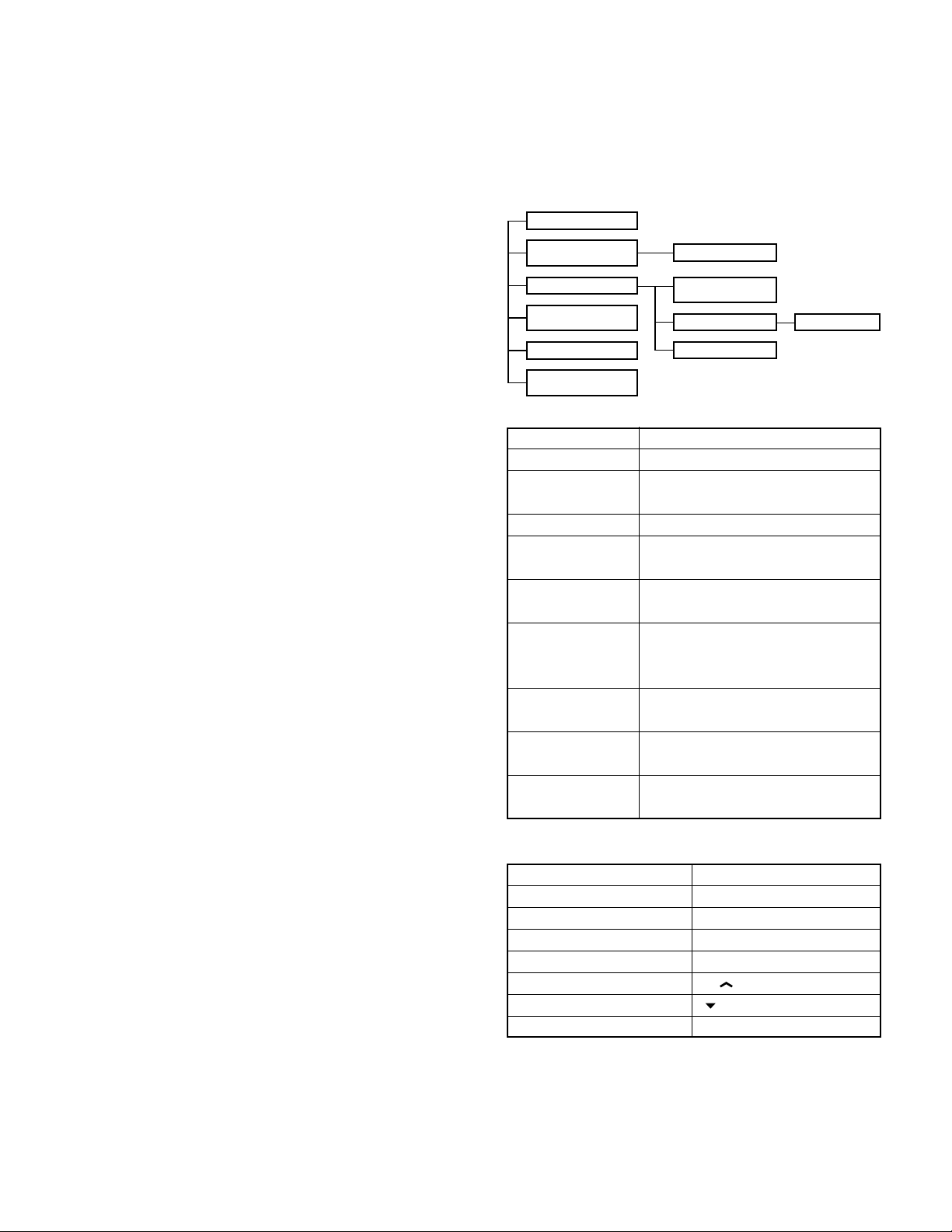
REALIGNMENT
1. Modes
Mode Function
User mode For normal use.
Panel test mode Used by the dealer to check the funda-
ment characteristics.
Panel tuning mode Used by the dealer to tune the radio.
PC mode Used for communication between the
radio and PC (IBM compatible).
Data programming Used to read and write frequency data
mode and other features to and from the radio.
PC test mode Used to check the radio using the PC.
This feature is included in the FPU.
See panel tuning.
Firmware program- Used when changing the main program
ming mode of the flash memory.
Clone mode Used to transfer programming data from
one radio to another.
Self programming Frequency, signalling and features write
mode to the radio.
2. How to Enter Each Mode
Mode Operation
User mode Power ON
Panel test mode
PC mode Received commands from PC
Panel tuning mode [Panel test mode]+[SCN]
Firmware programming mode
Clone mode [ ]+Power ON (Two seconds)
Self programming mode [A]+Power ON (Two seconds)
[SCN]+Power ON (Two seconds)
[CH ]+Power ON (Two seconds)
3. For the Panel Test Mode (TK-860G only)
Setting method refer to ADJUSTMENT.
3-1. For the Panel Tunning Mode
Setting method refer to ADJUSTMENT.
11
TK -860G/(N)/862G/(N
REALIGNMENT
)
4. Check Sum
Executing this function, “TUNING” apears on the display
of the TK-860G while calculation the check sum.
When the calculation is completed, the display returns to
normal and PC displays the check sum of the radio.
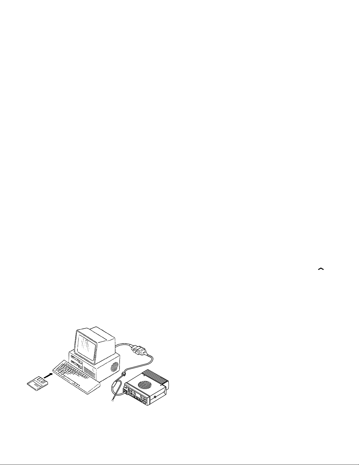
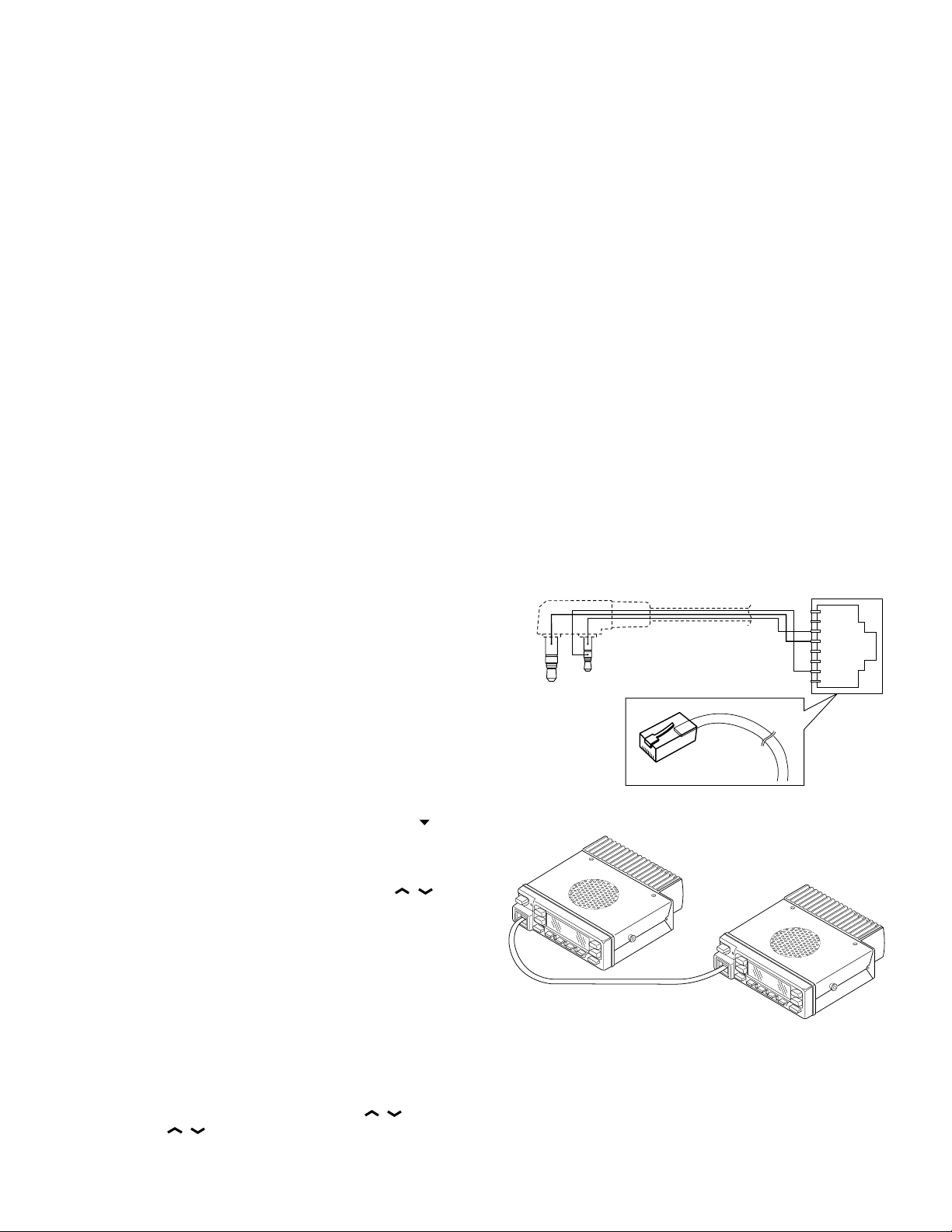
5. PC Mode
5-1. Preface
The TK-860G/862G transceiver is programmed using a
personal computer, a programming interface (KPG-46) and
programming software (KPG-67D).
The programming software can be used with an IBM PC
or compatible. Figure 1 shows the setup of an IBM PC for
programming.
5-2. Connection Procedure
1. Connect the TK-860G/862G to the personal computer
with the interface cable.
2. When the Power is switched on, user mode can be entered immediately. When the PC sends a command, the
radio enters PC mode.
When data is transmitted from transceiver, the red LED
blink.
When data is received by the transceiver, the green LED
blink.
Notes :
• The data stored in the personal computer must match
model type when it is written into the flash memory.
• Change the TK-860G/862G to PC mode, then attach the
interface cable.
5-3. KPG-46 Description
(PC programming interface cable : Option)
The KPG-46 is required to interface the TK-860G/862G
with the computer. It has a circuit in its D-subconnector (25pin) case that converts the RS-232C logic level to the TTL
level.
The KPG-46 connects the modular microphone jack of
the TK-860G/862G to the computers RS-232C serial port.
KPG-46
IBM-PC
5-4. Programming Software KPG-67D Description
The KPG-67D is programming software for the transceiver supplied on two 3.5" floppy disks. This software runs
under MS-DOS 3.1 or later on an IBM-PC or compatible machine.
The data can be input to or read from the transceiver and
edited on the screen. The programmed or edited data can
be printed out. It is also possible to tune the transceiver.
We recommend that install the KPG-67D for example to
harddisk first then use it.
6. Firmware Programming Mode
6-1. Preface
Flash memory is mounted on the TK-860G/862G. This
allows the TK-860G/862G to be upgraded when new features are released in the future. (For details on how to obtain the firmware, contact Customer Service.)
6-2. Connection Procedure
Connect the TK-860G/862G to the personal computer
(IBM PC or compatible) with the interface cable (KPG-46).
(Connection is the same as in the PC Mode.)
6-3. Programming
1. Start up the programming software (KPG-67D), select
“firmware program” in the “Program” item, and press
the Return key on your personal computer. This starts up
the firmware programmer.
2. The top screen is displayed. Press any key to advance to
the next screen.
3. Set the communications speed (normally, 57600 bps)
and communications port in the Setup item.
4. Set the firmware to be updated by File select (=F1).
5. Turn the TK-860G/862G Power ON with the [CH
switch held down. Hold the switch down for two sec-
onds until the display changes to “PROG 576”, the
BUSY/TX LED lights orange. When “PROG 576” ap-
pears, release your finger from the switch.
6. Check the connection between the TK-860G/862G and
the personal computer, and make sure that the TK-860G/
862G is in Program mode.
7. Press F10 on the personal computer. A window opens
on the display to indicate the writing progress. When the
TK-860G/862G starts to receive data, the BUSY/TX LED
lights green.
8. If writing ends successfully, the LED on the TK-860G/
862G goes off and the checksum is displayed.
(Since the TK-862G does not have a display, check the
checksum with the FPU (KPG-67D).)
9. If you want to continue programming other TK-860G/
862G, repeat steps 5 to 8.
]
12
KPG-67D
TK-860G/862G
Fig. 1
TK-860G /(N)/862G/(N
MBL
PSB
GND
PTT/TXD
ME
MIC
HOOK/RXD
CM
GND
REMOTE/TXD
PTT/RXD
8
1
1
8
REALIGNMENT
)
Notes :
• To start the Firmware Programmer from KPG-67D, the
FPRO path must be set up by the KPG-67D setup.
• This mode cannot be entered if the Firmware programming mode is set to Disable in the Programming software (KPG-67D).
• When programming the firmware, it is recommend to
copy the data from the floppy disk to your hard disk before you update the radio firmware.
Directly copying from the floppy disk to the radio may not
work because the access speed is too slow.
6-4. Function
1. If you press the [MON] switch while “PROG 576” is displayed, the checksum is displayed. If you press the
[MON] switch again (while the checksum is displayed),
“PROG 576” is redisplayed.
2. If you press the [A] switch while “PROG 576” is displayed, the display changes to “PROG 192” to indicate
that the write speed is low speed (19200 bps). If you
press the [A] switch again while “PROG 192” is displayed, the display changes to “PROG 384”, and the
write speed becomes the middle speed (38400 bps). If
you press the [A] switch again while “PROG 384” is displayed, the display returns to "PROG 576".
Note :
TK-862G indicate
19200 bps : The LED flashes green and red alternately.
38400 bps : The LED flashes orange.
57600 bps : The LED lights orange.
Normally, write in the high-speed mode.
you press the [SCN] key, the currectly selected number is
determined, and the display shifts to the left. If you
press the [SCN] key after entering the password in this
procedure, “CLONE” is displayed if the entered password is correct. If the password is incorrect, “CLN
LOCK” is redisplayed.
4. Power on the slave TK-860G.
5. Connect the cloning cable (No. E30-3382-05) to the
modular microphone jacks on the master and slave.
6. Press the [SCN] key on the master while the master displays “CLONE”. The data of the master is sent to the
slave. While the slave is receiving the data, “–PC–” is
displayed. When cloning of data is completed, the master displays “END”, and the slave automatically operates
in the User mode. The slave can then be operated by the
same program as the master.
7. The other slave can be continuously cloned. When the
[SCN] key on the master is pressed while the master displays “END”, the master displays “CLONE”. Carry out
the operation in step 4 to 6.
Note :
You can clone the programmed data between the trans-
ceiver frequency version must be same.
Clone cable
E30-3411-05 (TK-860G → TK-360G/370G)
7. Clone Mode (TK-860G only)
Programming data can be transferred from one radio to
another by connecting them via their modular microphone
jacks. The operation is as follows (the transmit radio is the
master and the receive radio is the slave).
1. Turn the master TK-860G power ON with the [
held down. If the password is set to the TK-860G, the
TK-860G displays “CLN LOCK”. If the password is not
set, the TK-860G displays “CLONE”.
2. When “CLN LOCK” is displayed, only the [CH
and [SCN], and [0] to [9] keys can be accepted. When
you enter the correct password, and “CLONE” is dis-
played, the TK-860G can be used as the cloning master.
The following describes how to enter the password.
3. How to enter the password with the microphone keypad;
If you press a key while “CLN LOCK” is displayed, the
number that was pressed is displayed on the TK-860G.
Each press of the key shifts the display in order to the
left. When you enter the password and press the [SCN]
key, “CLONE” is displayed if the entered password is
correct. If the password is incorrect, “CLN LOCK” is
redisplayed.
How to enter the password with the [CH
If the [CH
/ ] key is pressed while "CLN LOCK" is dis-
/ ] key;
played, numbers (0 to 9) are displayed flashing. When
] key
/ ] key
Cloning cable
(E30-3382-05)
Fig. 2
8. Self Programming Mode (TK-860G only)
Write mode for frequency data and signalling etc. Mainly
used by the person maintaining the user equipment.
13
TK -860G/(N)/862G/(N
REALIGNMENT
)
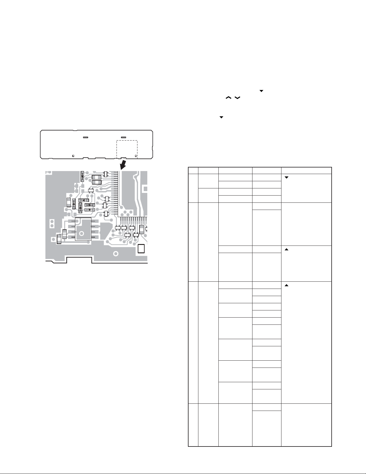
8-1. Enter to the Self Programming Mode
Remove D507 (Figure 3) from the TX-RX unit. Hold down
the [A] key and turn the power switch on. When enter the
self programming mode, “SELF” is displayed. The mode
changes autoically to Model Select Mode in about one second, and set up radio type, radio band & channel type and
frequency version.
Note :
This mode (self programming mode) cannot be set when
it has been disabled with the FPU.
TX-RX unit B/2
Foil side
IC502
D507
D505
5
IC505
8
4
1
50
51
Fig. 3
9. Channel Setting Mode
Each channel can be setup in its action mode by using
the panel keys.
•Pressing [MON] when “SELF” is diaplyed, sets channel
setting mode.
• Select an item set using [
with the [CH
/ ].
• The data displayed using [D/A] is stored in the memory
and then proceeds to the next item.
• Pressing [
] proceeds to the next item without storing it
in the memory.
• Press [MON] to set the display to “SELF” and return to
reset (default) status.
The setup items for channel setting mode are listed be-
low.
No. Function
Select 1~128 __1-__1._ [ ] : Group selection/
channel __1-128._ Channel selection
Select 1~128 __1.-__1_ change
group 128.-__1_
1RX Step STP__250 Display when an item
frequency
2RX Off - - - - - - - - [ ] : Off/QT/DQT
signalling
3TX Step STP__250 Display when an item
frequency
Choices Display Remarks
2.5kHz~1MHz STP___1M is selected or when a
Blank R. - - - - - - - [ ] : Frequency on/
100.0000~ R.450.0000 blank switching
550.0000MHz The right most dot
QT 67.0~250.3Hz
(EIA mode) QT_250.3_ [A] : Mode switching
QT 67.0~254.1Hz
(0.1Hz step mode)
DQT 000~777 DQT000N*
(Normal) DQT777N*
(1 step mode)
DQT 023~754 DQT023N_
(Normal) DQT754N_
(Standard table mode)
DQT 000~777 DQT000I*
(Inverse) DQT777I*
(1 step mode)
DQT 023~754 DQT023I_
(Inverse) DQT754I_
(Standard table mode)
2.5kHz~1MHz STP___1M is selected or when a
] then change the selection
step is changed
(about 0.5 seconds)
[A] : Step change
5.0, 6.25kHz, 1MHz step
indicates 50Hz digit
(On=5, Off=0)
QT__67.0_ switching
QT__67.0* [SCN] : Normal/
QT_254.1* Inverse switching
step is changed
(about 0.5 seconds)
[A] : Step change
5.0, 6.25kHz, 1MHz step
14
TK -860G/(N)/862G/(N
REALIGNMENT
)
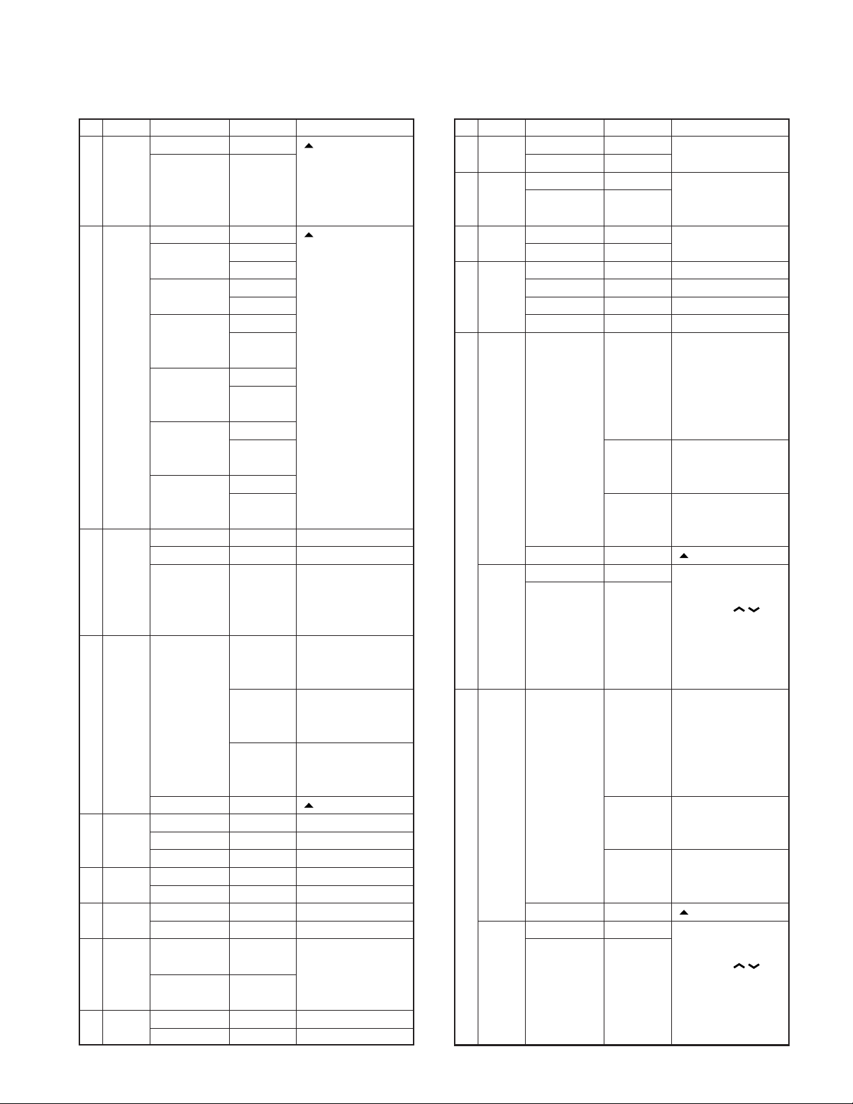
No. Function
4TX Off - - - - - - - - [ ] : Off/QT/DQT
signalling
5
Option signal-
ling (Only
when DTMF/
2-tone is se-
lected for sig-
nalling type)
6ID 000~ ___ID___ Display when an item
(Only 9999999999 is selected (about
when 0.5 seconds)
DTMF is
selected
for sig- more digits, scroll it)
nalling - - - - - 987 Display when a code
type) is input (Input it with
7 Busy No BCL_NO__ ←Default
channel Type 1 BCL_1___
lockout Type 2 BCL_2___
8 Beat No SHFT_NO_ ←Default
shift Yes SHFT_YES
9RF High power PWR_H___ ←Default
power Low power PWR_L___
10 Wide/ Wide WIDE____ ( ) : E type
Narrow (Wide 5k) (WIDE_5K_) NE : Not used
(Wide 5k/
Wide 4k)
11 Scan DELETE SCAN_DEL Not used for 8ch
Delete/Add
Choices Display Remarks
Blank T. - - - - - - - [ ] : Frequency on/
100.0000~ T.450.0000 blank switching
550.0000MHz The right most dot
indicates 50Hz digit
(On=5, Off=0)
QT 67.0~250.3Hz
(EIA mode) QT_250.3_ [A] : Mode switching
QT 67.0~254.1Hz
(0.1Hz step mode)
DQT 000~777 DQT000N*
(Normal) DQT777N*
(1 step mode)
DQT 023~754 DQT023N_
(Normal) DQT754N_
(Standard table mode)
DQT 000~777 DQT000I*
(Inverse) DQT777I*
(1 step mode)
DQT 023~754 DQT023I_
(Inverse) DQT754I_
(Standard table mode)
Off NONE____ ←Default
DTMF DTMF____
2-TONE 2TONE___
Clear - - - - - 000 [ ] : Data clear
Narrow NARROW__
(Wide 4k) (WIDE_4K_)
ADD SCAN_ADD ←Default
QT__67.0_ switching
QT__67.0* [SCN] : Normal/
QT_254.1* Inverse switching
12345678 Display of the current
setting (If it is 8 or
DTMF key)
No. Function
12 Priority No P.CH_NO__ Not used when (Scan)
channel Yes P.CH_YES_ priority is not fixed
13 Home No H.CH_NO__ Not used when home
channel Yes H.CH_YES_ channel is not set in
14
Compander
15 PTT ID OFF P.ID_OFF_
16 Begin 000~ _BOT_ID_ Not valid if Dial ID=
of TX ID
(Only off, or EOT is set
when Display when an item
DTMF/ is selected (about
2-tone is
selected
for sig- setting (If it is 8 or
nalling more digits, scroll it)
type) - - - - - 987 Display when a code
Begin of
TX ID Encode A-E _BOT___ A off, or EOT is set.
(Only when
5-tone is
selected for
signalling
type)
17 End of 000~ _EOT_ID_ Not valid if Dial ID=
TX ID
(Only off, or BOT is set
when Display when an item
DTMF/ is selected (about
2-tone is
selected
for sig- setting (If it is 8 or
nalling more digits, scroll it)
type) - - - - - 987 Display when a code
End of
TX ID Encode A-H _EOT___A off, or BOT is set.
(Only when
5-tone is
selected for
signalling
type)
Choices Display Remarks
key assignment
No COMP_NO_ E : Not used
Yes COMP_YES
Begin of TX P.ID_1___
End of TX P.ID_2___
Both P.ID_3___
9999999999999999
12345678 Display of the current
Blank - - - - - - - - [ ] : Data clear
OFF _BOT_OFF Not valid if PTT ID=
9999999999999999
12345678 Display of the current
Blank - - - - - - - - [ ] : Data clear
OFF _BOT_OFF Not valid if PTT ID=
disable and PTT ID=
0.5 seconds)
is input (Input it with
DTMF key)
Turn the [CH / ] key.
disable and PTT ID=
0.5 seconds)
is input (Input it with
DTMF key)
Turn the [CH / ] key.
15
TK -860G/(N)/862G/(N
REALIGNMENT
)
No. Function
18
Decode 1 ID
(Only when
Choices Display Remarks
OFF DEC1_OFF
Decode A-F DEC1___A
5-tone is
selected for
signalling
type)
19
Decode 2 ID
(Only when
OFF DEC2_OFF
Decode A-F DEC2___A
5-tone is
selected for
signalling
type)
20
CALL 1 ID
(Only when
OFF _CL1_OFF
Encode A-H _CL1___A
5-tone is
selected for
signalling
type)
21
CALL 2 ID
(Only when
OFF _CL2_OFF
Encode A-H _CL2___A
5-tone is
selected for
signalling
type)
22
Transpond ID
(Only when
OFF _TSP_OFF
Encode A-H _TSP___A
5-tone is
selected for
signalling
type)
23 PTT ID OPEN PTTM_YES
monitor DISABLE PTTM_NO_
(Only when
5-tone is
selected for
signalling
type)
24 CALL 1 OPEN CL1M_YES
monitor DISABLE CL1M_NO_
(Only when
5-tone is
selected for
signalling
type)
25 CALL 2 OPEN CL2M_YES
monitor DISABLE CL2M_NO_
(Only when
5-tone is
selected for
signalling
type)
16
Turn the [CH / ] key.
Turn the [CH / ] key.
Turn the [CH / ] key.
Turn the [CH / ] key.
Turn the [CH / ] key.
Turn the [CH / ] key.
Turn the [CH / ] key.
Turn the [CH / ] key.
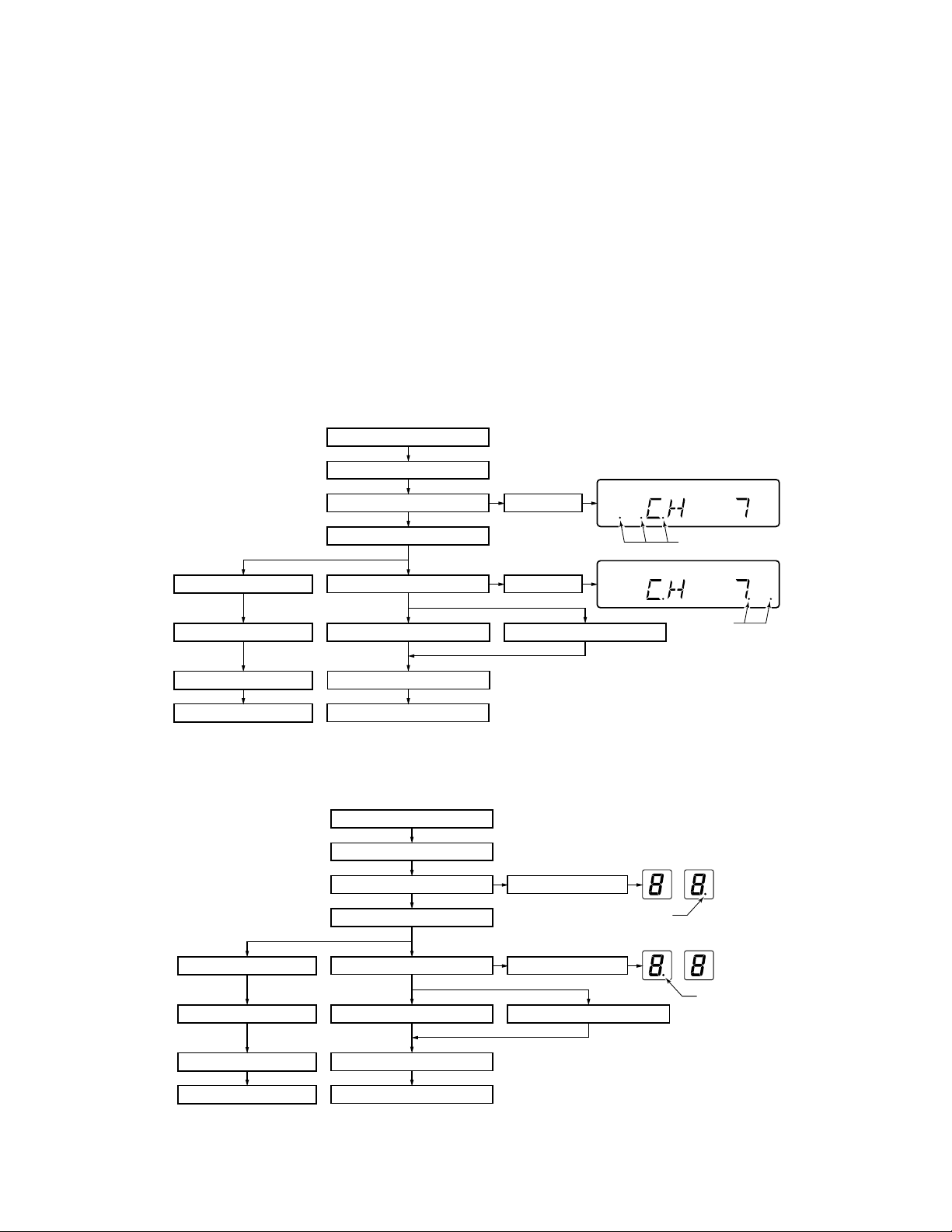
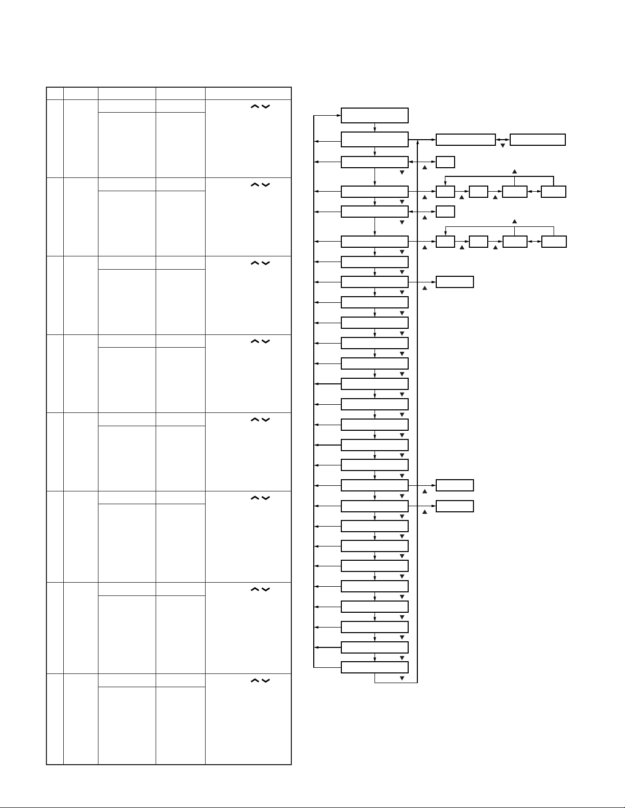
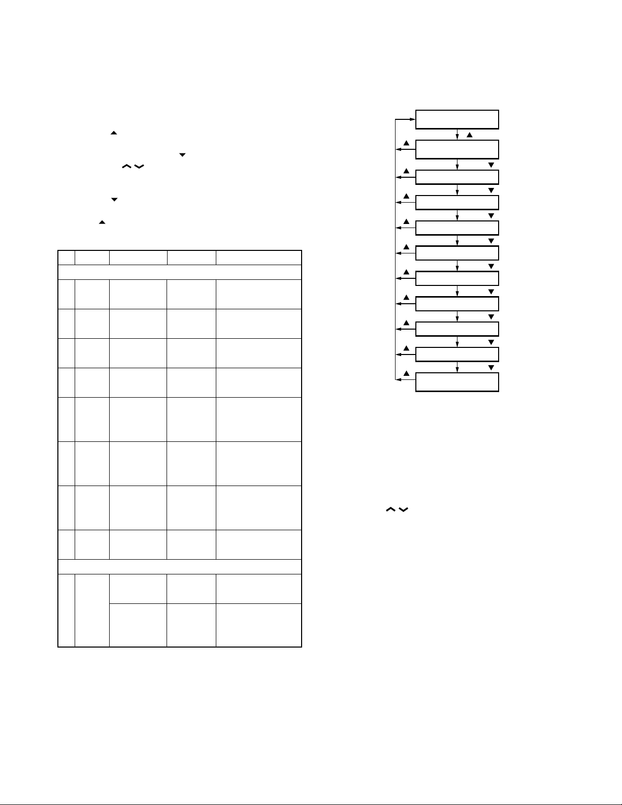
9-1. Flow Chart
Self programming
mode
[MON]
[MON]
[MON]
[MON]
[MON]
[MON]
[MON]
[MON]
[MON]
[MON]
[MON]
[MON]
[MON]
[MON]
[MON]
[MON]
[MON]
[MON]
[MON]
[MON]
[MON]
[MON]
[MON]
[MON]
[MON]
[MON]
Option signalling
Busy channel lockout
Beat shift yes/no
RF power high/low
for
Compander yes/no
[MON]
Channel setting
mode
[D/A]
RX frequency
[D/A]/[ ]
RX signalling
[D/A]/[ ]
TX freuency
[D/A]/[ ]
TX signalling
[D/A]/[ ]
[D/A]/[ ]
ID
[D/A]/[ ]
[D/A]/[ ]
[D/A]/[ ]
[D/A]/[ ]
Wide/Narrow
[D/A]/[ ]
Scan delete/add
[D/A]/[ ]
Priority channel Not used when (Scan) priority is not fixed.
[D/A]/[ ]
Home channel
[D/A]/[ ]
[D/A]/[ ]
PTT ID
[D/A]/[ ]
Begin of TX ID
[D/A]/[ ]
End of TX ID
[D/A]/[ ]
Decode 1 ID
[D/A]/[ ]
Decode 2 ID
[D/A]/[ ]
CALL 1 ID
[D/A]/[ ]
CALL 2 ID
[D/A]/[ ]
Transpond ID
[D/A]/[ ]
PTT ID monitor
[D/A]/[ ]
CALL 1 monitor
[D/A]/[ ]
CALL 2 monitor
[D/A]/[ ]
Channel selection Group selection
OFF
[ ]
OFF QT
[ ]
[ ]
[ ]
[ ]
E : Wide 5k/4k, NE : Not used
Not used when home channel is not set
in key assignment.
E : Not used
[ ]
[ ]
[ ] [ ]
OFF
OFF QT
[ ] [ ]
Data clear
Data clear
Data clear
[ ]
[ ]
DQT N DQT I
[SCN]
[ ]
DQT N DQT I
[SCN]
TK-860G /(N)/862G/(N
REALIGNMENT
)
10. Function Setting Mode
All channels can be set up together in the action mode by
using the panel keys.
• Pressing [
setting mode.
• Select an item set using [
with the [CH
• The data displayed using [D/A] is stored in the memory
and then proceeds to the next item.
• Pressing [
in the memory.
• Press [
status.
No. Function
1 Power YES/NO PONT_YES Default : Yes
on tone
2 Control YES/NO CNTT_YES Default : Yes
tone
3 Warning YES/NO WART_YES Default : Yes
tone
4
Time out
timer 15s step
5 TOT OFF, 1~10/ TOTP_OFF Cannot be set when
pre-alert
time Default : Off
6 TOT OFF, 1~60/ TOTK_OFF Cannot be set when
rekey 1s step TOT is off
time Default : Off
7 TOT OFF, 1~15/ TOTS_OFF Cannot be set when
reset 1s step TOT is off
time
8 Squelch 0~9/1 step SQL__5__ Default : 5
level
9 Panel Enable PTM__ENA ←Default
test/ Not used for TK-762G
panel Disable PTM__DIS
tuning
mode
] when “SELF” is displayed, sets the function
] then change the selection
/ ].
] proceeds to the next item without storing it
] to display “SELF” and return to reset (default)
Choices Display Remarks
Optional feature
OFF, 15~600/ TOT__180 Default : 180s
1s step TOT is off
Others
10-1. Flow Chart
Self programming
mode
[ ]
Function setting
[ ]
Power on tone yes/no
[ ]
Control tone yes/no
[ ]
Warning tone yes/no
[ ]
Time out timer
[ ]
TOT pre-alert time
[ ]
TOT rekey time
[ ]
TOT reset time
[ ]
[ ]
Squelch level
Panel tuning mode
[ ]
mode
[D/A]/[ ]
[D/A]/[ ]
[D/A]/[ ]
[D/A]/[ ]
[D/A]/[ ]
[D/A]/[ ]
[D/A]/[ ]
[D/A]/[ ]
[D/A]/[ ]
Panel test/
11. Memory Reset Mode (TK-860G only)
You can clear all settings you made in self programming
mode, or you can return to the original display.
• Press [SCN] while “SELF” is displayed will change the
display to “CANCEL”.
• Press [CH
CEL” and “READY”.
• When “READY” is displayed, pressing [SCN] will set all
data to default, and “CLEAR” will appear on the display.
Press [SCN] again to display “SELF”.
• When “CANCEL” is displayed, pressing [SCN] will cancel
the reset, and “SELF” will be displayed.
/ ] to change the display between “CAN-
17
TK -860G/(N)/862G/(N
INSTALLATION
)
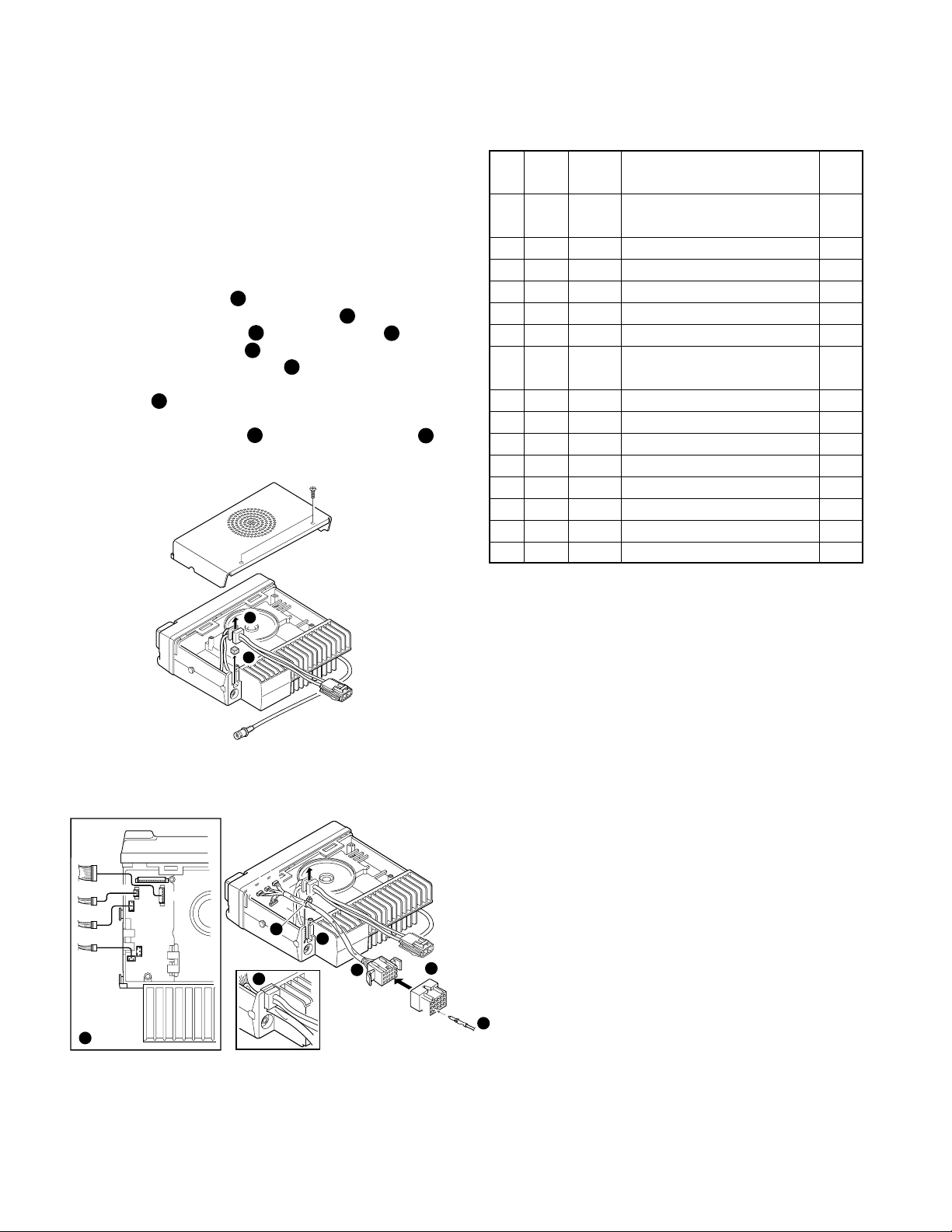
1. Accessory Connection Cable (KCT-19 : Option)
The KCT-19 is an accessory connection cable for con-
necting external equipment. The connector has 15 pins and
the necessary signal lines are selected for use.
1-1. Installing the KCT-19 in the transceiver
1. Remove the upper half of the transceiver case, and lift
the DC cord bushing ( ) from the chassis.
2. Remove the pad as shown in Figure 1 ( ).
3. Insert the KCT-19 cable ( ) into the chassis ( ).
The wire harness band ( ) must be inside the chassis.
4. Replace the DC cord bushing ( ).
5. Connect the KCT-19 to the TX-RX unit (A/2) as shown in
Figure 2 ( ).
7
6. Connect the KCT-19 to the external accessory by inserting the crimp terminal ( ) into the square plug ( ),
both of which are supplied with the KCT-19.
1
2
3
5
6
8 9
1
4
1-2. KCT-19 Accessory Port Function
No. No. Name Function
(A)
(B,C,D,E)
1 D-2 DTC Data channel control/ *1
External hook input
2 D-5 ME External microphone ground
3 D-3 IGN Ignition sense input
4 D-1 DEO Receiver detector output
5 D-6 MI External microphone input
6 B-2 E Ground
7 B-3 SB Switched B+, DC 13.2V output.
Maximum 1A
8 D-7 PTT External PTT input *1
9 D-4 DI Data modulation input
10 B-1 HOR Horn alert/call output
11 D-8 SQ Squelch detect output Busy : H *1
12 C-1 SP Speaker audio output.
13 E-1 AM
14 E-2 MM MIC mute input, active high
15 E-3 EMG Foot switch input, active low *2
*1 : MDT mode
*2 : Emergency mode
Speaker mute input, active high
Note
2
Fig. 1
D
CN5
E
B
C
7
CN3
CN8
CN4
E
C
B
B
D
5
4
9
6
3
Crimp terminal
(E23-0613-05)
A
13
15
Square plug
(E09-1571-05)
1
3
Contact
8
Fig. 2
18
TK-860G /(N)/862G/(N
TX-RX UNIT
(A/2)
ANT
KCT-19
CN2
R134
R133
R135
INSTALLATION
)
2. Accessory Terminal (TX-RX Unit)
2-1. External Connector Accessory Terminal Method
No. Name I/O Description Note
CN1 1 8C O DC 8V output
2 5S O DC 5V output
3 AUX5 O
4 AUX6 O
5 NC – Non-connection
6 AUX3 O SQ : Squelch detect output *1
7 AUX1 I PTT : External PTT input *1
8 AUX4 O
9 AUX2 I DTC : Data channel control/
External hook input
I CHDATA : Channel control
serial data input
10 ALT I Alert tone input
11 AFO O Receiver audio signal output
12 AFI I Receiver audio signal input
13 MII I Transmit audio signal input
14 MIO O Transmit audio signal output
15 GND – Ground
CN3 1 HOR O Horn alert/call output
2 E – Ground
3 SB O Switched B+, DC 13.2V
output, Maximum 1A
CN4 1 DEO O Receiver detector output
Level : 0.5Vrms
(Standard modulation)
2 DTC I Data channel control/
External hook input
3 IGN I Ignition sense input
4 DI I Data modulation input
5 ME – External microphone ground
6 MI I External microphone input
7 PTT I
8 SQ O Squelch detect output
CN5 1 AM I
2 MM I MIC mute input, active high
3 EMG I EMG : Foot switch input, *2
CN7 1 PA/LI O Relay for PA function KAP-1
2 SPO O Audio signal output to KAP-1
3 SPI I
CN8 1 SP O Audio signal output to
2 E – Ground
*1 : MDT mode
*2 : Emergency mode
External PTT input, active low
Speaker mute input, active high
active low
control
O
PA/LI ON : High, PA/LI OFF : Low
Audio signal input from KAP-1
internal/external speaker
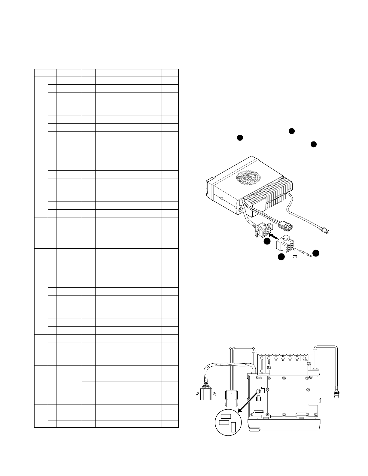
3. Ignition Sense Cable (KCT-18 : Option)
The KCT-18 is an optional cable for enabling the ignition
function. The ignition function lets you turn the power to the
transceiver on and off with the car ignition key.
If you use the Horn Alert function or the Manual Relay
function, you can turn the function off while driving with the
ignition key.
3-1. Connecting the KCT-18 to the Transceiver
1. Install the KCT-19 in the transceiver. (See the KCT-19
section.)
2. Insert the KCT-18 lead terminal ( ) into pin 3 of the
square plug ( ) supplied with the KCT-19, then insert
1
the square plug into the KCT-19 connector ( ).
KCT-19
3
Fig. 3
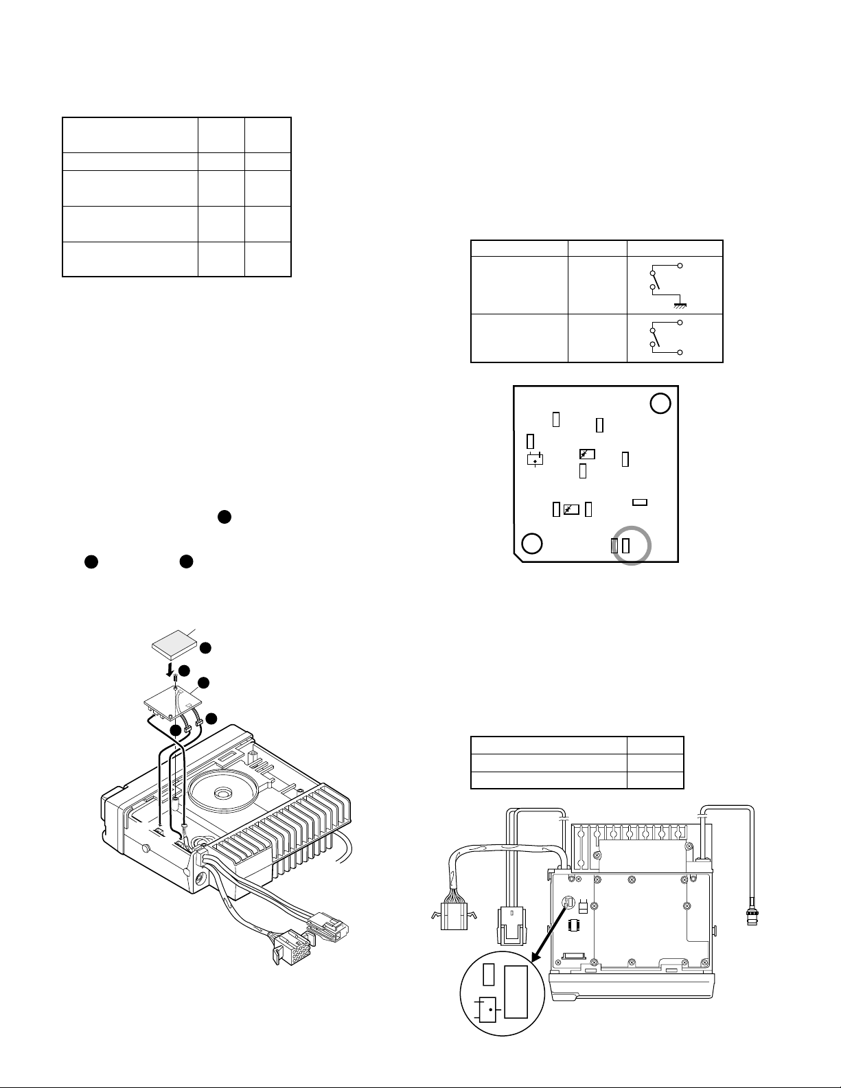
3-2. Modifying the Transceiver
Modify the transceiver as follows to turn the power or
the Horn Alert or Manual Relay function on and off with the
ignition key.
1. Remove the lower half of the transceiver case.
2. Set jumper resistors (0Ω) R134 and R135 of the TX-RX
unit (A/2) as shown in Table 1.
Fig. 4
2
3
1
3
13
Contact
6
15
1
2
KCT-18
19
TK -860G/(N)/862G/(N
R1
TX-RX UNIT
(A/2)
ANT
KCT-19
CN2
Q19
R122
R153
INSTALLATION
)
Operation when KCT-18 R134 R135
is connected
Enable Enable ← KCT-18 cannot
Power on/off and Horn Disable Enable be connected
Alert or AUX-A on/off
Horn Alert or AUX-A Enable Disable
on/off
Disable Disable ← Power cannot
be turned on
Table 1 R134 and R135 setup chart
4. PA/HA Unit (KAP-1 : Option)
4-1. Installing the KAP-1 in the Transceiver
The Horn Alert (max. 2A drive) and Public Address functions are enabled by inserting the KAP-1 W1 (3P; white/
black/red) into CN3 on the TX-RX unit, inserting W2 (3P;
green) into CN7 on the TX-RX unit, and connecting the KCT19 (option) to CN2 and CN3 of the KAP-1.
• Installation procedure
1. Open the upper case of the transceiver.
2. Insert the two cables ( ) with connectors from the
KAP-1 switch unit into the connectors on the transceiver.
3. Secure the switch unit board to the chassis with a screw
( ). The notch ( ) in the board must be placed at the
3
front left side.
4. Attach the cushion on the top of the KAP-1 switch unit.
1
2
4-2. Modifying the Transceiver
• Horn alert
The signal from pin 4 of IC9 on the TX-RX unit turns Q5
and Q1 on and off and drives KAP-1 HA relay K2 to drive the
horn with a maximum of 2A.
The default output is HR1. The relay open output can be
obtained between HR1 and HR2 by removing R1 in the KAP-
1.
R1 Output form
HR1 (Default) Enable
HR2 Disable
HR1
HR1
HR2
Fig. 6 KAP-1 foil side view
CN1
CN2
CN3
CN3
CN7
3
1
Cushion
(G13-1710-04)
4
3
2
W1
W2
1
Fig. 5
• Public address
The signal from pin 13 of IC9 on the TX-RX unit drives PA
relay K1 in the KAP-1 and switches the audio power amplifier output between the external PA system (through KCT-
19) and internal and external speakers.
To use the PA function, R153 on the TX-RX unit must be
removed.
R153
Use the PA function Disable
Do not use the PA function Enable
KCT-19
20
Fig. 7
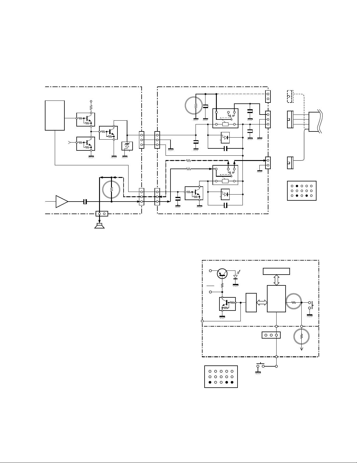
INSTALLATION
IC502
CPU
6
Q506
87
88
25 20
$R705
Attach
0
Power
switch
MBL
MBL
SB
Q505
Key
backlight
LCD
IC510
1
3
CN5
R142
47K
Remove
IC14
KCT-19
15 pin
KCT-18
Foot
switch
Control section
TX-RX section
Outside
13 1
3615
KCT-19 Terminal
3 : Ignition sense
6 : Earth
15 : Foot switch
4-3. Others
If the PA and HR2 are not necessary and the speaker output is output to an external unit through the KCT-19, connect
the KCT-19 C connector to CN8 on the TX-RX unit.
TK-860G /(N)/862G/(N
)
TX-RX UNIT
IC9
Shift
register
Q1
Q6
13
IGN
Audio
power amp
IC13
KAP-1 (SWITCH UNIT : X41-3380-20)
Q1 : DTD114EK
HOR
SB
PA/LI
SPO
SPI
W1
E
W2
D1,2 : 1SS193
1
2
3
1
2
C2
3
R3 0
R4 0
Q1
1000P
R1 0
C1
1000P
C5 1000P
±
C3 0.01
K1
±
C4 0.01
K2
C6
+
C7
D1
+
D2
8C
Q5
4
Q6
R21
Q1
R153
+
1
2
CN8
E
SP
Internal/External
speaker
CN3
D2
CN7
1000P
1000P
CN1
1
2
CN2
1
2
3
CN3
1
2
HR2
NC
HR1
E
SB
PAO/LIO
E
C
GRN
KCT-19
BRN
ORG
YEL
B
C
GRN
KCT-19 Terminal
13 10 1
12
15
6 : Earth
10 : HR1
12 : PA (HR2)
36
Fig. 8
5. Emergency Mode
5-1. Transceiver Modification Procedure
• Install the foot switch
When the switch is treaded on, the radio enters the emergency mode.
• Change the power switch circuit
and off with the power switch. The power switch turns the
LCD backlight and display on and off. (The power is
switched on and off by IGNITION SENSE.)
Install the foot switch through the KCT-19 and KCT-18.
TX-RX unit (B/2) : Control section
$R705 : Attach (R92-1252-05, 0Ω)
TX-RX unit (A/2) : RF section
R142 : Remove (RK73GB1J473J, 47kΩ)
Once the transceiver is modified, it cannot be turned on
Fig. 9
21
 Loading...