

Page 1

TK-7302/ TK-8302
TK-7302H/ TK-8302H
TK-7302HV/ TK-8302HU
VHF FM TRANSCEIVER/ UHF FM TRANSCEIVER
INSTRUCTION MANUAL
ÉMETTEUR-RÉCEPTEUR FM VHF/ ÉMETTEUR-RÉCEPTEUR FM UHF
MODE D’EMPLOI
TRANSCEPTOR FM VHF/ TRANSCEPTOR FM UHF
MANUAL DE INSTRUCCIONES
© B62-2167-20 (K,K2)
09 08 07 06 05 04 03 02
Page 2

Page 3

VHF FM TRANSCEIVER/ UHF FM TRANSCEIVER
TK-7302/ TK-8302
TK-7302H/ TK-8302H
TK-7302HV/ TK-8302HU
INSTRUCTION MANUAL
ENGLISH
Firmware Copyrights
The title to and ownership of copyrights for firmware
embedded in Kenwood product memories are reserved for
JVC KENWOOD Corporation.
Page 4

Terminal Description
ACC (D-SUB 15 Pin Connector)
Pin NO. Pin Name Description Specification I/O Notes
1 SB DC Power Output
2 IGN Ignition signal Input
3 PA Loudspeaker Output 4 Ω O
4 DO Audio Output 500 mV p-p O
5 DI Audio Input 5 k Ω I
6 FNC1 Programmable High Impedance I/O
7 FNC2 Programmable High Impedance I/O
8 FNC3 Programmable High Impedance I/O
9 FNC4 Programmable High Impedance I/O
10 FNC5 Programmable High Impedance I/O
11 FNC6 Programmable High Impedance I/O
12 5C DC Power Output 5 V, Max 100 mA O
13 HR1 Horn Alert Signal Output Max 3A O
14 HR2 Horn Alert Signal Output Max 3A O
15 GND Ground Ground
Speaker Jack (3.5 mm phone jack) 4W/ 4 Ω
13.6 V ±15 %
Power ON: more than 8V
Power OFF: less than 6V
Pin NO. Pin Name Description Specification I/O Notes
1 SPO External Speaker Output 4 Ω O
3 GND Ground Ground
O
I
−
−
DC Input Connector
Pin NO. Pin Name Description Specification I/O Notes
Red B DC Power Input
Black GND Ground Ground I
Microphone Jack
13.6 V ±15 %
I
Pin NO. Pin Name Description Specification I/O Notes
1 MBL Backlight of Microphone
2 SB DC Power Output
3 GND Ground Ground
4 PTT PTT/ PC Serial Data from radio High Impedance I
5 ME MIC Ground Ground
6 MIC MIC Signal Input 600 Ω I
7 HOOK Hook / PC Serial Data to radio High Impedance I
8 DM MIC Data Detection High Impedance I/O
Antenna Connector
Impedance is 50 Ω.
−
13.6 V ±15 %
O
O
−
−
Page 5

THANK YOU
We are grateful you have chosen Kenwood for your personal mobile applications.
This instruction manual covers only the basic operations of your mobile radio. Ask your dealer for
information on any customized features they may have added to your radio.
NOTICES TO THE USER
◆ Government law prohibits the operation of unlicensed transmitters within the territories under
government control.
◆ Illegal operation is punishable by fine and/or imprisonment.
◆ Refer service to qualified technicians only.
SAFETY: It is important that the operator is aware of, and understands, hazards
common to the operation of any transceiver.
◆ EXPLOSIVE ATMOSPHERES (GASES, DUST, FUMES, etc.)
Turn OFF your transceiver while taking on fuel or while parked in gasoline service stations. Do
not carry spare fuel containers in the trunk of your vehicle if your transceiver is mounted in the
trunk area.
◆ INJURY FROM RADIO FREQUENCY TRANSMISSIONS
Do not operate your transceiver when somebody is either touching the antenna or standing
within 2 to 3 feet (60 to 90 cm) of it, to avoid the possibility of radio frequency burns or related
physical injury.
◆ DYNAMITE BLASTING CAPS
Operating the transceiver within 500 feet (150 m) of dynamite blasting caps may cause them
to explode. Turn OFF your transceiver when in an area where blasting is in progress, or where
“TURN OFF TWO-WAY RADIO” signs have been posted. If you are transporting blasting caps
in your vehicle, make sure they are carried in a closed metal box with a padded interior. Do not
transmit while the caps are being placed into or removed from the container.
One or more of the following statements may be applicable:
FCC WARNING
This equipment generates or uses radio frequency energy. Changes or modifications to this
equipment may cause harmful interference unless the modifications are expressly approved in the
instruction manual. The user could lose the authority to operate this equipment if an unauthorized
change or modification is made.
INFORMATION TO THE DIGITAL DEVICE USER REQUIRED BY THE FCC
This equipment has been tested and found to comply with the limits for a Class B digital device,
pursuant to Part 15 of the FCC Rules. These limits are designed to provide reasonable protection
against harmful interference in a residential installation.
This equipment generates, uses and can generate radio frequency energy and, if not installed and
used in accordance with the instructions, may cause harmful interference to radio communications.
However, there is no guarantee that the interference will not occur in a particular installation. If this
equipment does cause harmful interference to radio or television reception, which can be determined
by turning the equipment off and on, the user is encouraged to try to correct the interference by one
or more of the following measures:
• Reorient or relocate the receiving antenna.
• Increase the separation between the equipment and receiver.
• Connect the equipment to an outlet on a circuit different from that to which the receiver is
connected.
• Consult the dealer for technical assistance.
i
Page 6
PRECAUTIONS
Observe the following precautions to prevent fire, personal injury, and transceiver
damage.
• Do not attempt to configure the transceiver while driving; it is too dangerous.
• Do not disassemble or modify the transceiver for any reason.
• Do not expose the transceiver to long periods of direct sunlight, nor place it near heating
appliances.
• If an abnormal odor or smoke is detected coming from the transceiver, switch the
transceiver power off immediately, and contact your Kenwood dealer.
• Use of the transceiver while you are driving may be against traffic laws. Please check
and observe the vehicle regulations in your area.
• Do not use options not specified by Kenwood.
◆ The transceiver operates in 12 V negative ground systems only! Check the battery polarity and
voltage of the vehicle before installing the transceiver.
◆ Use only the supplied DC power cable or a Kenwood optional DC power cable.
◆ Do not cut and/or remove the fuse holder on the DC power cable.
For passenger safety, install the transceiver securely using the supplied mounting bracket and
screw set so the transceiver will not break loose in the event of a collision.
CONTENTS
GETTING STARTED ................................................................................................1
GETTING ACQUAINTED .........................................................................................3
PROGRAMMABLE FUNCTIONS .............................................................................4
BASIC OPERATIONS ..............................................................................................5
SCAN ........................................................................................................................6
DTMF CALLS ...........................................................................................................7
SIGNALING ..............................................................................................................8
FleetSync: ALPHANUMERIC 2-WAY PAGING FUNCTION ....................................9
ADVANCED OPERATIONS ...................................................................................10
BACKGROUND OPERATIONS..............................................................................12
ii
Page 7
GETTING STARTED
Note: The following instructions are for use by your Kenwood dealer, an authorized Kenwood
service facility, or the factory.
SUPPLIED ACCESSORIES
Carefully unpack the transceiver. We recommend that you identify the items
listed below before discarding the packing material. If any items are missing or
have been damaged during shipment, file a claim with the carrier immediately.
DC power cable (with fuses). . . . . . . . . . . . . . . . . . . . . . . . . . . . . . . . . . . . . . . . . . . . . . . . . . . . . . 1
• 10 A fuse (TK-7302/ TK-8302) . . . . . . . . . . . . . . . . . . . . . . . . . . . . . . . . . . . . . . . . . . . . . . . . . 2
• 15 A fuse (TK-7302H/ TK-7302HV/ TK-8302H/ TK-8302HU) . . . . . . . . . . . . . . . . . . . . . . . . . 2
Mounting Bracket . . . . . . . . . . . . . . . . . . . . . . . . . . . . . . . . . . . . . . . . . . . . . . . . . . . . . . . . . . . . . . 1
Screw set
• 5 x 16 mm self-tapping screw. . . . . . . . . . . . . . . . . . . . . . . . . . . . . . . . . . . . . . . . . . . . . . . . . .4
• Hex-headed screw with washer . . . . . . . . . . . . . . . . . . . . . . . . . . . . . . . . . . . . . . . . . . . . . . . . 4
• Spring washer . . . . . . . . . . . . . . . . . . . . . . . . . . . . . . . . . . . . . . . . . . . . . . . . . . . . . . . . . . . . . 4
• Flat washer. . . . . . . . . . . . . . . . . . . . . . . . . . . . . . . . . . . . . . . . . . . . . . . . . . . . . . . . . . . . . . . . 4
Microphone (with cable)
• KMC-30 (TK-7302H/ TK-8302H) . . . . . . . . . . . . . . . . . . . . . . . . . . . . . . . . . . . . . . . . . . . . . . . 1
• KMC-35 (TK-7302/ TK-7302HV/ TK-8302/ TK-8302HU) . . . . . . . . . . . . . . . . . . . . . . . . . . . . . 1
Microphone hanger (with 4 x 16 mm self-tapping screws) . . . . . . . . . . . . . . . . . . . . . . . . . . . . . . . 1
Instruction manual . . . . . . . . . . . . . . . . . . . . . . . . . . . . . . . . . . . . . . . . . . . . . . . . . . . . . . . . . . . . . 1
PREPARATION
Various electronic equipment in your vehicle may malfunction if they are not properly protected
from the radio frequency energy which is present while transmitting. Typical examples include
electronic fuel injection, anti-skid braking, and cruise control. If your vehicle contains such
equipment, consult the dealer for the make of vehicle and enlist his/her aid in determining if they
will perform normally while transmitting.
■ Power Cable Connection
The transceiver operates in 12 V negative ground systems only! Check the battery polarity and
voltage of the vehicle before installing the transceiver.
1 Check for an existing hole, conveniently located in the firewall, where the
power cable can be passed through.
• If no hole exists, use a circle cutter to drill a hole, then install a rubber grommet.
2 Run the power cable through the firewall and into the engine compartment.
3 Connect the red lead to the positive (+) battery terminal and the black lead
to the negative (–) battery terminal.
• Place the fuse as close to the battery as possible.
1
Page 8
4 Coil the surplus cable and secure it with a retaining band.
• Be sure to leave enough slack in the cables so the transceiver can be removed
for servicing while keeping the power applied.
■ Installing the Transceiver
For passenger safety, install the transceiver securely using the supplied mounting bracket and
screw set, so the transceiver will not break loose in the event of a collision.
Note: Before installing the transceiver, check how far the mounting screws will extend below
the surface. When drilling mounting holes, be careful not to damage vehicle wiring or parts.
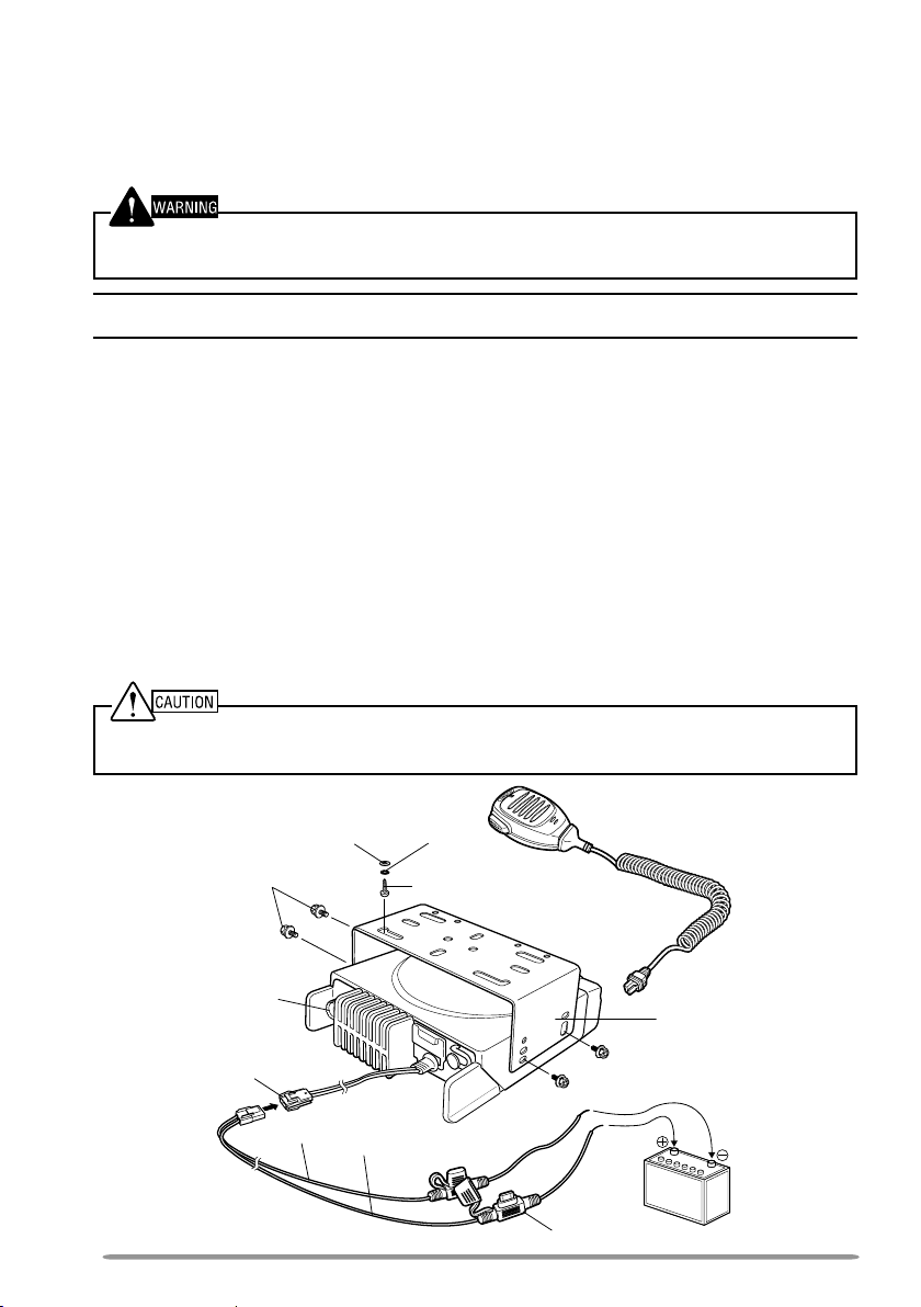
1 Mark the position of the holes in the dash, using the mounting bracket as a
template. Using a 4.2 mm (5/32 inch) drill bit, drill the holes, then attach the
mounting bracket using the supplied screws.
• Mount the transceiver within easy reach of the user and where there is sufficient
space at the rear of the transceiver for cable connections.
2 Connect the antenna and the supplied power cable to the transceiver.
3 Slide the transceiver into the mounting bracket and secure it using the
supplied hex-headed screws.
4 Mount the microphone hanger in a location where it will be within easy
reach of the user.
• The microphone and microphone cable should be mounted in a place where they
will not interfere with the safe operation of the vehicle.
When replacing the fuse in the DC power cable, be sure to replace it with a fuse of the same
value. Never replace a fuse with one that is rated with a higher value.
Flat
washer
M4 x 6 mm
Hex-headed screw
Antenna
connector
Power input
connector
Black (–) cable
DC power cable
Spring
washer
5 x 16 mm
Self-tapping screw
Red (+) cable
Microphone
Mounting bracket
Fuse
2
12 V vehicle
battery
Page 9
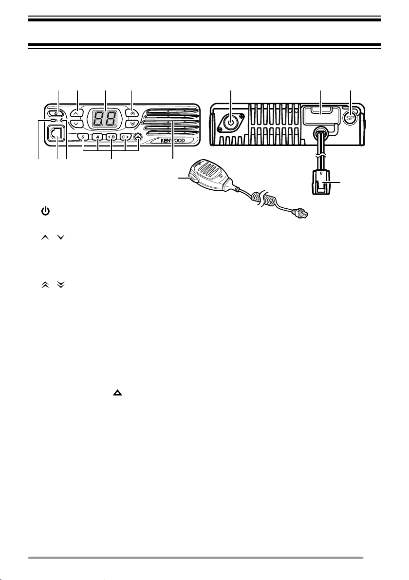
FRONT/REAR PANEL
GETTING ACQUAINTED
:
B> 2
=
@
.
;
8
ACC.
① (Power) switch
Press to switch the transceiver ON or OFF.
② / keys
Press to activate their programmable functions {page 4}.
③ Display
Refer to page 4.
④ / keys
Press to activate their programmable functions {page 4}.
⑤ TX/RX Indicator
Lights red while transmitting. Lights green while receiving a signal. Flashes
orange when receiving an optional signaling call.
⑥ Microphone jack
Insert the microphone plug into this jack.
⑦ Status Indicator
Lights during a specified mode, based on dealer programming.
⑧ S / A / <B / C> / keys
Press to activate their programmable functions {page 4}.
⑨ Speaker
Internal speaker.
⑩ PTT switch
Press this switch, then speak into the microphone to call a station.
⑪ Antenna connector
Connect the antenna to this connector.
⑫ACC connector
Connect the ACC to this connector, via the KCT-60.
⑬ External speaker jack
Connect an external speaker to this jack.
⑭ Power input connector
Connect the DC Power Cable to this connector.
3
Page 10

DISPLAY
The display shows the channel number and the 2 dots show various modes of
operation.
The left and right dots on the display can be programmed to indicate specific
modes of operation, as listed below.
• AUX
• Horn Alert
• Lone Worker
• Priority Channel
• Scan Delete/Add
• Scrambler
• Talk Around
• Zone Delete/Add
The right dot will blink during special operations (such as Autodial and OST).
PROGRAMMABLE FUNCTIONS
The , , , , S, A, <B, C>, and keys can be programmed with the functions
listed below. Ask your dealer for details on these functions.
• None
• 2-tone Encode
• AUX
• Autodial
• Channel Down
• Channel Entry
• Channel Up
• Direct Zone Channel
1
• Display Brightness
• Emergency
2
• Horn Alert
• Lone Worker
• Monitor
• Monitor Momentary
• Operator Selectable Tone
• Paging Call
• Public Address
• Scan Del/Add
• Scan On/Off
• Scrambler
• Send the GPS Data
• Status 1
• Status 2
• Squelch Level
• Squelch Off
• Squelch Off Momentary
• Talk Around
• Volume Down
• Volume Up
• Zone Down
• Zone Up
1
Direct Zone Channel can be programmed only on the S, A, <B, C>, and keys.
2
Emergency can be programmed only on the key.
4
Page 11

BASIC OPERATIONS
SWITCHING POWER ON/ OFF
Press to switch the transceiver ON.
• A beep sounds and the display illuminates.
• If the Transceiver Password function is programmed, “PS” will appear on the display
when the power is turned ON. Refer to “Transceiver Password”, below.
Press again to switch the transceiver OFF.
■ Transceiver Password
To enter the password:
1 Press / to select a digit.
• When using a keypad, simply enter the password digits and proceed to step 3.
2 Press C> to accept the entered digit and move to the next digit.
• Press A or # to delete an incorrect digit. Press and hold A or # to delete all
digits.
• Repeat steps 1 and 2 to enter the entire password.
3 Press S or to confirm the password.
• If you enter an incorrect password, the transceiver remains locked.
ADJUSTING THE VOLUME
Press the Volume Up key to increase the volume. Press the Volume Down key
to decrease the volume.
If Squelch Off has been programmed onto a key, you can use that function to
listen to background noise while adjusting the volume level.
SELECTING A ZONE AND CHANNEL
Select the desired zone and channel using the keys programmed as Zone Up/
Zone Down and Channel Up/ Channel Down.
• “G1” (Zone 1) appears on the display.
TRANSMITTING/ RECEIVING
1 Select your desired zone and channel.
2 Press microphone PTT switch and speak into the microphone to transmit.
Release the PTT switch to receive.
• For best sound quality at the receiving station, hold the microphone approximately
1.5 inches (3 ~ 4 cm) from your mouth.
5
Page 12

SCAN
Scan monitors for signals on the transceiver channels. While scanning, the
transceiver checks for a signal on each channel and only stops if a matching
signal is present.
To start/stop scanning, press the key programmed as Scan On/Off.
• “Sc” appears on the display during Scan.
• When a signal is detected, Scan pauses at that channel. The transceiver will remain on
the busy channel until the signal is no longer present, at which time Scan resumes.
Note: To use Scan, there must be at least 2 channels added to the scanning sequence.
PRIORITY SCAN
If a Priority channel has been programmed, the transceiver will automatically
change to the Priority channel when a call is received on that channel, even if call
is being received on a normal channel.
• “P” appears on the display to indicate the Priority channel (depending on dealer setting).
TEMPORARY CHANNEL LOCKOUT
During scan, you can temporarily remove specific channels from the scanning
sequence by pressing the key programmed as Scan Delete/Add while Scan is
paused at the undesired channel. To temporarily remove a zone, press and hold
Scan Delete/Add while Scan is paused at a channel in the undesired zone.
• The channel/zone is no longer scanned. However, when scanning is ended and
restarted, the Scan settings return to normal.
SCAN DELETE/ADD
You can add and remove zones and/or channels to and from your scan list.
1 Select your desired zone and/or channel.
2 Press the key programmed as Scan Delete/Add to remove a channel or press
and hold the key for approximately 1 second to remove a zone.
• When a channel is added to scan, “cA” appears on the display. When it is removed,
“cd” appears on the display.
• When a zone is added to scan, “GA” appears on the display. When it is removed,
“Gd” appears on the display.
6
Page 13

SCAN REVERT
The Scan Revert channel is the channel selected when you press the PTT switch
to transmit during scan. Your dealer can program one of the following types of
Scan Revert channels:
• Selected: The last channel selected before scan.
• Selected + Talkback: Same as “Selected”, plus you can respond to calls on the
channel at which scan is paused.
• Priority: The Priority channel.
• Priority + Talkback: Same as “Priority”, plus you can respond to calls on the channel
at which scan is paused.
• Last Called + Selected: The last channel on which you receive a call or the last
channel selected before scan, whichever operation occured latest.
DTMF CALLS
Note: To make DTMF calls, you must use an optional microphone with a DTMF keypad.
MANUAL DIALING
1 Press and hold the PTT switch.
2 Enter the desired digits using the keypad.
• If Keypad Auto-PTT is enabled by your dealer, you do not need to press the PTT
switch to transmit; you can make the call simply by pressing the keys.
AUTODIAL
Autodial allows you to quickly call DTMF numbers that have been programmed
onto your transceiver.
1 Press the key programmed as Autodial or the microphone key.
• “Ad” appears on the display.
2 Enter the desired memory location number (1 ~ 9).
3 Press the PTT switch to make the call.
REDIALING
1 Press the key programmed as Autodial or the microphone key.
• “Ad” appears on the display.
2 Press the microphone 0 key.
• “rd” appears on the display.
• If there is no data in the redial memory, an error tone will sound.
3 Press the PTT switch to make the call.
Note: Switching the transceiver power OFF clears the redial memory.
7
Page 14

STUN
This function is used when a transceiver is stolen or lost. When the transceiver
receives a call containing a stun code, the transceiver becomes disabled. The
stun code is cancelled when the transceiver receives a call with a revive code.
• “St” appears on the display while the transceiver is stunned.
SIGNALING
QUIET TALK (QT)/ DIGITAL QUIET TALK (DQT)
Your dealer may have programmed QT or DQT signaling on your transceiver
channels. A QT tone/ DQT code is a sub-audible tone/code which allows you to
ignore (not hear) calls from other parties who are using the same channel.
OPTIONAL SIGNALING
Your dealer may also program several types of optional signaling for your
transceiver channels.
2-tone Signaling: 2-tone Signaling opens the squelch only when your
transceiver receives a call containing matching 2 tones.
DTMF Signaling: DTMF Signaling opens the squelch only when the transceiver
receives a call containing a matching DTMF code.
FleetSync Signaling: Refer to “SELCALL (SELECTIVE CALLING)” on page 9.
MDC-1200: MDC-1200 is a data system using Audio
(AFSK). Transceivers communicate
1800 Hz tones.
at a 1200 baud rate, using 1200 Hz and
Frequency Shift Keying
OPERATOR SELECTABLE TONE (OST)
You can change the preset encode and decode tones for the selected channel.
Up to 16 OST pairs can be pre-programmed by your dealer.
1 Select your desired channel.
2 Press the key programmed as Operator Selectable Tone or press and hold
the microphone key.
• “ot” appears on the display, followed by the current OST number.
3 Press <B and C> to select the desired OST number.
4 Use the transceiver the same as in a regular call; press the PTT switch to
transmit and release it to receive.
5 To exit OST mode and return to the preset encode and decode tones, press S.
8
Page 15

FleetSync: ALPHANUMERIC 2-WAY PAGING FUNCTION
FleetSync is an Alphanumeric 2-way Paging Function and is a protocol owned by
JVC KENWOOD Corporation.
Note: If set up by your dealer, your transceiver may use the MDC-1200 feature in place of
FleetSync. MDC-1200 and FleetSync cannot be operated simultaneously.
SELCALL (SELECTIVE CALLING)
A Selcall is a voice call to a particular station or to a group of stations.
■ Transmitting
1 Select your desired zone and channel.
2 Press the microphone PTT switch and begin your conversation.
■ Receiving
If enabled by your dealer, an alert tone will sound and the LED will blink when
a Selcall has been received.
To respond to the call, press the PTT switch and speak into the microphone.
■ Identification Codes
An ID code is a combination of a 3-digit Fleet number and a 4-digit ID number.
Each transceiver must have its own Fleet and ID number.
Note: The ID range may be limited by programming.
PAGING CALL
1 Select your desired zone and channel.
2 Press and hold the key programmed as Paging Call for 1 second to transmit
your PTT List ID, to request a call.
STATUS MESSAGE
You can transmit pre-programmed status messages by pressing the keys
programmed as Status 1 and Status 2.
Status messages are 2-digit codes ranging from 10 to 99 (80 ~ 99 are reserved
for special messages).
• “dt” appears on the display when sending a status message. “Ed” appears on the
display when receiving an acknowledgement. “Er” appears on the display during status
message no reply.
GPS REPORT
If a GPS unit (NMEA-0183 format) is installed on your transceiver, you can press
the key programmed as Send the GPS data to send your location data.
9
Page 16

ADVANCED OPERATIONS
EMERGENCY CALLS
If your transceiver has been programmed with the Emergency function, you can
make emergency calls.
1 Press and hold the key programmed as Emergency.
• Depending on the delay time programmed into your transceiver, the length of time
you must hold the Emergency key will vary.
• When the transceiver enters Emergency mode, the transceiver will change to the
Emergency channel and begin transmitting based on how the transceiver is set up.
2 To exit Emergency mode, press and hold the Emergency key again.
• If the Emergency mode completes the preset number of cycles, Emergency mode
will automatically end and the transceiver will return to normal.
■ Lone Worker Mode
Lone Worker Mode is a safety feature built into the transceiver. If the
transceiver is not operated for a pre-programmed period of time, the
transceiver will emit a tone and automatically enter Emergency operation.
Press and hold the key programmed as Lone Worker for 2 seconds to toggle
the Lone Worker function ON or OFF.
• “Ln” appears on the display while Lone Worker is activated.
TALK AROUND
During interruptions in service (such as a power failure), you can continue to
communicate by using the Talk Around feature. Talk Around allows you to
communicate directly with other transceivers without the use of a repeater, as
long they are not too far away or there are no geographical obstacles in the way.
Press the key programmed as Talk Around to toggle the Talk Around function ON
or OFF.
• “tA” appears on the display while Talk Around is activated.
VOICE SCRAMBLER
Note: Your dealer can activate the built-in scrambler function, or they can add a more secure
optional scrambler board to your transceiver. Ask your dealer for details.
The built-in scrambler prevent others from easily listening in on your calls. When
activated, the transceiver distorts your voice so that anybody listening to your
conversation will not be able to clearly hear what you are saying.
In order for members of your own group to hear your call while you are using the
scrambler, all members must activate their scrambler functions.
Press the key programmed as Scrambler to toggle the Scrambler function ON or
OFF.
• “Sr” appears on the display while the Scrambler is activated.
10
Page 17

When using an optional scrambler board, you can change the internal and
external scrambler codes:
1 Press and hold the key programmed as Scrambler for 2 seconds.
• “co” (code) appears on the display, followed by the current scrambler code.
2 Press <B and C> to select your desired scrambler code.
3 Press S or
• After changing your scrambler code, be sure to inform all of your group members of
the new code so they can also reset their transceivers. The scrambler function will
not work with transceivers set up with different scrambler codes.
to store the new setting.
MONITOR/ SQUELCH OFF
You can use the key programmed as Monitor or Squelch Off to listen to weak
signals that you cannot hear during normal operation and to adjust the volume
when no signals are present on your selected channel.
Your dealer can program a key with one of 4 functions:
• Monitor: Press to deactivate QT, DQT, DTMF, or FleetSync Signaling. Press again to
return to normal operation.
• Monitor Momentary: Press and hold to deactivate QT, DQT, DTMF, or FleetSync
Signaling. Release to return to normal operation.
• Squelch Off: Press to hear background noise. Press again to return to normal
operation.
• Squelch Off Momentary: Press and hold to hear background noise. Release to return
to normal operation.
■ Squelch Level
If a key has been programmed as Squelch Level, you can readjust your
transceiver’s squelch level:
1 Press the key programmed as Squelch Level.
• “SL” appears on the display, followed by the current squelch level.
2 Press <B and C> to select the desired squelch level from 0 to 9.
3 Press S or to store the new setting.
PUBLIC ADDRESS (PA)
The PA system can only be used with an optional relay unit and external speaker.
1 Press the key programmed as Public Address to activate the Public Address
function.
• “PA” appears on the display.
2 Press and hold the PTT switch, then speak into the microphone to make your
address through the external speaker.
3 Press the Public Address key again to exit Public Address.
11
Page 18

HORN ALERT
The Horn Alert function can only be used with an optional relay unit.
Press the key programmed as Horn Alert to toggle the Horn Alert function ON or
OFF.
• “HA” appears on the display while Horn Alert is activated.
BACKGROUND OPERATIONS
TIME-OUT TIMER (TOT)
The Time-out Timer is used to prevent you from using a channel for an extended
duration. If you continuously transmit for a preset time, the transceiver will stop
transmitting and an alert tone will sound. Release the PTT switch.
AUXILIARY PORT
Press the key programmed as AUX to activate the auxiliary port. The auxiliary
port is used with optional boards.
• “AU” appears on the display when the auxiliary port is active.
DISPLAY BRIGHTNESS
You can cycle the display brightness between high, low, and off by pressing the
key programmed as Display Brightness.
DIRECT ZONE CHANNEL
Press the key programmed as Direct Zone Channel to immediately select the
lowest channel of the lowest zone.
BUSY CHANNEL LOCKOUT (BCL)
If BCL is set up by your dealer, you will be unable to transmit if the channel is
already in use. Use a different channel or wait until the channel becomes free.
PTT ID
PTT ID is the transceiver unique ID code which is sent each time the PTT switch
is pressed and/or released.
COMPANDER
If programmed by your dealer for a channel, the compander will remove
excessive noise from transmitted signals, to provide higher clarity of signals.
VOICE ANNOUNCEMENT
When changing the channel, an audio voice will announce the new channel.
12
Page 19

ÉMETTEUR-RÉCEPTEUR FM VHF/ ÉMETTEUR-RÉCEPTEUR FM UHF
TK-7302/ TK-8302
TK-7302H/ TK-8302H
TK-7302HV/ TK-8302HU
MODE D’EMPLOI
FRANÇAIS
Droits d’auteur du micrologiciel
Le titre et la propriété des droits d’auteur pour le micrologiciel
intégré dans la mémoire du produit Kenwood sont réservés pour
JVC KENWOOD Corporation.
Page 20

Description de la borne
ACC (Connecteur D-SUB 15 broches)
N° de
broche
Nom de
broche
1 SB Sortie d’alimentation CC 13,6 V ± 15 % S
2 IGN Entrée du signal d’allumage
3 PA Sortie de haut-parleur 4 Ω S
4 DO Sortie audio 500 mV c-c S
5 DI Entrée audio 5 k Ω E
6 FNC1 Programmable Impédance élevée E/S
7 FNC2 Programmable Impédance élevée E/S
8 FNC3 Programmable Impédance élevée E/S
9 FNC4 Programmable Impédance élevée E/S
10 FNC5 Programmable Impédance élevée E/S
11 FNC6 Programmable Impédance élevée E/S
12 5C Sortie d’alimentation CC 5 V, Max 100 mA S
13 HR1
14 HR2
15 GND Terre Terre −
Sortie du signal d’avertissement par
klaxon
Sortie du signal d’avertissement par
klaxon
Description Caractéristiques E/S Remarques
Sous tension: plus de 8V
Hors tension: moins de 6V
Max 3A S
Max 3A S
E
Prise de haut-parleur (prise téléphonique 3,5 mm) 4W/ 4
N° de
broche
Connecteur d’entrée CC
N° de
broche
Rouge B Entrée d’alimentation CC 13,6 V ± 15 % E
Noir GND Terre Terre E
Prise du microphone
N° de
broche
Connecteur d’antenne
Impédance est 50 Ω.
Nom de
broche
1 SPO Sor tie de haut-parleur externe 4 Ω S
3 GND Terre Terre −
Nom de
broche
Nom de
broche
1 MBL Rétroéclairage du microphone − S
2 SB Sortie d’alimentation CC 13,6 V ± 15 % S
3 GND Terre Terre −
4 PTT Données série PTT/ PC de la radio Impédance élevée E
5 ME MIC Terre Terre −
6 MIC Entrée du signal MIC 600 Ω E
7 HOOK Données série Support/ PC vers la radio Impédance élevée E
8 DM Détection des données MIC Impédance élevée E/S
Description Caractéristiques E/S Remarques
Description Caractéristiques E/S Remarques
Description Caractéristiques E/S Remarques
Ω
Page 21

MERCI
Nous sommes heureux que vous ayez choisi Kenwood pour vos applications mobiles
personnelles.
Ce mode d’emploi ne reprend que le fonctionnement de base de votre radio mobile. Renseignez-vous auprès de
votre revendeur pour de plus amples informations relatives aux fonctions personnalisées qui ont pu être ajoutées
à votre radio.
AVIS AUX UTILISATEURS
◆ Une loi gouvernementale interdit l’usage sans licence des émetteurs radio sur les territoires régis par cette
autorité gouvernementale.
◆ Une utilisation illégale est passible d’amende ou d’emprisonnement.
◆ Pour l’entretien et la réparation, confiez l’appareil uniquement à des techniciens qualifiés.
SÉCURITÉ: Il est important que l’opérateur soit au courant des risques usuels associés à
l’exploitation d’un émetteur-récepteur.
AVERTISSEMENT
◆ ATMOSPHÈRES EXPLOSIVES (GAZ, POUSSIÈRE, FUMÉE, etc.)
Mettez l’émetteur-récepteur hors tension lorsque vous faites le plein d’essence ou lorsque vous garez votre
véhicule dans une station-service. Ne transportez pas de bidons d’essence dans le coffre arrière de votre
véhicule si votre émetteur-récepteur est installé dans cette zone.
◆ BLESSURES RÉSULTANT DE LA TRANSMISSION DE FRÉQUENCES RADIO
Afin d’éviter les risques de brûlures ou de blessures corporelles causées par les fréquences radio,
n’exploitez pas votre émetteur-récepteur lorsqu’une personne touche à l’antenne ou si elle se trouve dans
60 cm à 90 cm de celle-ci.
◆ DÉTONATEURS DE DYNAMITE
L’exploitation de l’émetteur-récepteur dans un rayon de 150 mètres d’un détonateur de dynamite pourrait
provoquer son explosion. Mettez votre émetteur-récepteur hors tension lorsque vous êtes dans une zone
de dynamitage en cours ou dans un endroit où des panneaux d’avertissement demandent de mettre les
émetteurs-récepteurs hors tension. Si vous transportez des détonateurs dans votre véhicule, assurez-vous
qu’ils se trouvent dans des contenants métalliques fermés dont l’intérieur est matelassé. N’émettez jamais
pendant qu’on place ou qu’on sort les détonnateurs de leur contenant.
F-i
Page 22

PRÉCAUTIONS
Veuillez respecter les points suivants afin d’éviter les risques d’incendie, de blessure
corporelle ou d’endommagement de l’émetteur-récepteur.
• Ne tentez pas de configurer l’émetteur-récepteur tout en conduisant, car cela est trop dangeureux.
• Ne démontez et ne modifiez sous aucun cas l’émetteur-récepteur.
• N’exposez pas l’émetteur-récepteur aux rayons directs du soleil pendant de longues périodes et ne
le placez pas près d’appareils chauffants.
• Si une odeur anormale ou de la fumée est générée par l’émetteur-récepteur, mettez
immédiatement l’émetteur-récepteur hors tension et contactez votre revendeur Kenwood.
• Il est possible que l’utilisation de l’émetteur-récepteur lors de la conduite soit contraire aux règles
de circulation. Veuillez vérifier et respecter les régulations routières de votre pays.
• N’utilisez pas les options non indiquées par Kenwood.
ATTENTION
◆ Cet émetteur-récepteur fonctionne uniquement avec un système de 12 V à masse négative! Vérifiez la
polarité et la tension de la batterie du véhicule avant d’installer l’émetteur-récepteur.
◆ Utilisez uniquement le câble d’falimentation CC fourni ou un câble d’alimentation CC Kenwood en option.
◆ Ne pas couper et/ou retirer le support de fusible sur le câble d’alimentation CC.
AVERTISSEMENT
Pour la sécurité du passager, et pour éviter que l’émetteur-récepteur ne se détache en cas de collision, fixez
solidement l’émetteur-récepteur en utilisant le support de montage et l’ensemble des vis.
TABLE DES MATIÈRES
POUR DÉMARRER ..................................................................................................1
FAMILIARISATION AVEC L’APPAREIL .....................................................................3
FONCTIONS PROGRAMMABLES ...........................................................................4
FONCTIONNEMENT DE BASE ...............................................................................5
BALAYAGE ................................................................................................................6
APPELS DTMF .........................................................................................................7
SIGNALISATION .......................................................................................................8
FleetSync: TÉLÉAVERTISSEUR BIDIRECTIONNEL ALPHANUMÉRIQUE ............9
OPÉRATIONS AVANCÉES .....................................................................................10
OPÉRATIONS EN ARRIÈRE PLAN .......................................................................12
F-ii
Page 23

POUR DÉMARRER
Remarque: Les instructions suivantes sont destinées à votre revendeur Kenwood, un centre de service autorisé
Kenwood ou l’usine de fabrication.
ACCESSOIRES FOURNIS
Déballez soigneusement l’émetteur-récepteur. Nous recommandons que vous identifiez
les articles de la liste ci-dessous avant de vous débarrasser des matériaux d’emballage. Si
un article manque ou a été endommagé pendant l’expédition, remplissez immédiatement
un formulaire de plainte auprès du transporteur.
Câble d’alimentation CC (avec fusibles) . . . . . . . . . . . . . . . . . . . . . . . . . . . . . . . . . . . . . . . . . . . . .1
• Fusible 10 A (TK-7302/ TK-8302). . . . . . . . . . . . . . . . . . . . . . . . . . . . . . . . . . . . . . . . . . . . . . . 2
• Fusible 15 A (TK-7302H/ TK-7302HV/ TK-8302H/ TK-8302HU) . . . . . . . . . . . . . . . . . . . . . . . 2
Support de montage . . . . . . . . . . . . . . . . . . . . . . . . . . . . . . . . . . . . . . . . . . . . . . . . . . . . . . . . . . . . 1
Ensemble de vis
• Vis taraudeuse 5 x 16 mm . . . . . . . . . . . . . . . . . . . . . . . . . . . . . . . . . . . . . . . . . . . . . . . . . . . . 4
• Vis à tête hexagonale et rondelle. . . . . . . . . . . . . . . . . . . . . . . . . . . . . . . . . . . . . . . . . . . . . . .4
• Rondelle à ressort . . . . . . . . . . . . . . . . . . . . . . . . . . . . . . . . . . . . . . . . . . . . . . . . . . . . . . . . . . 4
• Rondelle ordinaire . . . . . . . . . . . . . . . . . . . . . . . . . . . . . . . . . . . . . . . . . . . . . . . . . . . . . . . . . . 4
Microphone (avec câble)
• KMC-30 (TK-7302H/ TK-8302H) . . . . . . . . . . . . . . . . . . . . . . . . . . . . . . . . . . . . . . . . . . . . . . . 1
• KMC-35 (TK-7302/ TK-7302HV/ TK-8302/ TK-8302HU) . . . . . . . . . . . . . . . . . . . . . . . . . . . . . 1
Crochet à microphone (avec vis taraudeuse 4 x 16 mm) . . . . . . . . . . . . . . . . . . . . . . . . . . . . . . . . 1
Mode d’emploi . . . . . . . . . . . . . . . . . . . . . . . . . . . . . . . . . . . . . . . . . . . . . . . . . . . . . . . . . . . . . . . . 1
PRÉPARATION
AVERTISSEMENT
Divers équipements électroniques de votre véhicule peuvent mal fonctionner s’ils ne sont pas correctement
protégés contre l’énergie radiofréquence produite pendant l’émission. Par exemple, l’injection électronique,
le dispositif anti-blocage de frein et le régulateur de vitesse automatique. Si votre véhicule contient de
tels équipements, consultez le revendeur de votre véhicule et demandez-lui son aide pour déterminer s’ils
fonctionneront normalement pendant une émission.
■ Connexion du câble d’alimentation
ATTENTION
Cet émetteur-récepteur fonctionne uniquement avec un système de 12 V à masse négative! Vérifiez la
polarité et la tension de la batterie du véhicule avant d’installer l’émetteur-récepteur.
1 Vérifiez s’il est existe déjà un trou placé de façon pratique dans le pare-feu, à
travers lequel le câble d’alimentation peut être passé.
•
S’il n’y a pas de trou, utilisez un trépan pour percer un trou, puis installer un joint en caoutchouc.
2 Faites passer le câble d’alimentation à travers le pare-feu jusqu’à dans le
compartiment du moteur.
3 Connectez le fil rouge à la borne positive (+) de la batterie et le fil noir à la borne
négative (–) de la batterie.
• Placez le fusible aussi près que possible de la batterie.
F-1
Page 24

4 Enroulez le câble en trop et fixez-le avec une bande de retenue.
• Assurez-vous de laisser suffisamment de jeu aux câble de façon que l’émetteur-récepteur
puisse être retiré pour réparation tout en restant connecté à l’alimentation.
■ Installation de l’émetteur-récepteur
AVERTISSEMENT
Pour la sécurité du passager, et pour éviter que l’émetteur-récepteur ne se détache en cas de collision, fixez
solidement l’émetteur-récepteur en utilisant le support de montage et l’ensemble des vis.
Remarque: Avant d’installer l’émetteur-récepteur, vérifiez jusqu’où iront les vis de montage sous la surface.
Quand vous percez des trous de montage, faites attention de ne pas endommager le câblage ou des pièces
du véhicule.
1 Marquez la position des trous sur le tableau de bord, en utilisant le support de
montage comme repère. En utilisant une mèche de 4,2 mm, percez les trous, puis
fixez le support de montage en utilisant les vis fournis.
• Montez l’émetteur-récepteur dans un endroit facile à atteindre par l’utilisateur et où il y a
suffisamment d’espace à l’arrière de l’émetteur-récepteur pour les connexions.
2 Connectez l’antenne et le câble d’alimentation fourni à l’émetteur-récepteur.
3 Faites glisser l’émetteur-récepteur dans le support de montage et fixez-le en
utilisant les vis à tête hexagonale fournis.
4 Montez le crochet à microphone dans un endroit facile d’accès par l’utilisateur.
• Le microphone et le câble du microphone doivent être montés dans un endroit où ils ne
gêneront pas la conduite en toute sécurité du véhicule.
ATTENTION
Lors du remplacement du fusible dans le câble d’alimentation CC, assurez-vous de le remplacer par un
fusible de la même valeur. Ne le remplacez jamais pas un fusible d’une valeur supérieure.
Vis à tête hexagonale
Connecteur d’entrée
de l’alimentation
Câble d’alimentation CC
F-2
M4 x 6 mm
Connecteur
d’antenne
Rondelle
ordinaire
Câble noir (–)
Câble rouge (+)
Rondelle à
ressort
Vis taraudeuse 5 x 16 mm
Fusible
Microphone
Support de montage
Batterie de
véhicule de
12 V
Page 25

FAMILIARISATION AVEC L’APPAREIL
PANNEAU AVANT/ARRIÈRE
:
B> 2
=
@
.
;
8
a Commutateur (d’alimentation)
Appuyez sur ce commutateur pour mettre l’émetteur-récepteur sous ou hors tension.
b Touches
Appuyez sur ces touches pour activer leurs fonctions programmables {page 4}.
c Afficheur
Reportez-vous à la page 4.
d Touches
Appuyez sur ces touches pour activer leurs fonctions programmables {page 4}.
e Indicateur TX/RX
S’allume en rouge pendant la transmission. S’allume en vert lors de la réception d’un
signal. Clignote en orange lors de la réception un appel de signalisation optionnel.
f Prise de microphone
Insérez la fiche du microphone dans cette prise.
g Indicateur d’état
S’allume dans un mode donné, en fonction de la programmation du vendeur.
h Touches S / A / <B / C> /
Appuyez sur ces touches pour activer leurs fonctions programmables {page 4}.
i Haut-parleur
Haut-parleur interne.
j Commutateur PTT
Appuyez sur ce commutateur, puis parlez dans le microphone pour appeler une station.
k Connecteur d’antenne
Connectez l’antenne à ce connecteur.
l Connecteur ACC
Connectez ACC à ce connecteur, via le KCT-60.
m Prise pour haut-parleur externe
Connectez un haut-parleur externe à cette prise.
n Connecteur d’entrée de l’alimentation
Connectez le câble d’alimentation CC à ce connecteur.
/
/
ACC.
F-3
Page 26

AFFICHEUR
L’afficheur montre le numéro de canal et les 2 points indiquent divers modes de
fonctionnement.
Les points gauche et droit de l’afficheur peuvent être programmés pour indiquer les modes
de fonctionnement spécifiques de la liste ci-dessous.
• AUX
• Avertissement par klaxon
• Travailleur seul
• Canal prioritaire
• Suppr./ajout au balayage
• Embrouilleur
• Talk around
• Effacement/ajout de zone
Le point droit clignote pendant des opérations spéciales (telles que la composition automatique
et OST).
FONCTIONS PROGRAMMABLES
Les touches , , , , S, A, <B, C> et peuvent être programmées avec les fonctions
de la liste ci-dessous. Consultez votre revendeur pour les détails sur ces fonctions.
• Aucune
• Codage sur 2 tonalité
• AUX
• Composition automatique
• Canal bas
• Saisie du canal
• Canal haut
• Canal de zone directe
1
• Luminosité de l’afficheur
• Urgence
2
• Avertissement par klaxon
• Travailleur seul
• Surveillance
• Surveillance momentanée
• Tonalité sélectionnable par l’opérateur
• Sonorisation
• Suppr./ajout au balayage
• Mise en/hors service du balayage
• Embrouilleur
• Émettre les données de GPS
• État 1
• État 2
• Niveau du silencieux
• Silencieux désactivé
• Silencieux désactivé momentané
• Talk around
• Volume bas
• Volume haut
• Zone bas
• Zone haut
• Appel de messagerie
1
Le canal de zone directe peut être programmé uniquement sur les touches S, A, <B, C> et .
2
L’urgence peut être programmée uniquement sur la touche .
F-4
Page 27

FONCTIONNEMENT DE BASE
MISE SOUS/ HORS TENSION
Appuyez sur pour mettre l’émetteur-récepteur sous tension.
• Un bip est émis et l’afficheur s’allume.
• La fonction Mot de passe émetteur-récepteur est programmée, “PS” apparaît sur l’afficheur quand
l’appareil est mis sous tension. Reportez-vous à “Mot de passe émetteur-récepteur”, ci-dessous.
Appuyez de nouveau sur pour mettre l’émetteur-récepteur hors tension.
■ Mot de passe émetteur-récepteur
Pour entrer le mot de passe:
1 Appuyez sur
• Lors de l’utilisation d’un clavier, entrez simplement les chiffres du mot de passe et passez à
l’étape 3.
2 Appuyez sur C> pour valider le chiffre entré et passer au chiffre suivant.
• Appuyez sur A ou # pour supprimer un chiffre incorrect. Appuyez sur la touche A ou # et
maintenez-la enfoncée pour supprimer tous les chiffres.
• Répétez les étapes 1 et 2 pour entrer le mot de passe entièrement.
3 Appuyez sur S ou pour valider le mot de passe.
• Si vous entrez un mot de passe incorrect, l’émetteur-récepteur reste verrouillé.
RÉGLAGE DU VOLUME
Appuyez sur la touche Volume haut pour augmenter le volume. Appuyez sur la touche
Volume bas pour diminuer le volume.
Si Silencieux désactivé a été programmé sur une touche, vous pouvez utiliser cette
fonction pour écouter le bruit de fond lors du réglage du niveau de volume.
/ pour choisir un chiffre.
SÉLECTION D
Sélectionnez la zone et le canal souhaités en utilisant les touches programmées pour
Zone haut/ Zone bas et Canal haut/ Canal bas.
• “G1” (Zone 1) apparaît sur l’afficheur.
UNE ZONE ET D’UN CANAL
’
TRANSMISSION/ RÉCEPTION
1 Sélectionnez votre zone et votre canal préférés.
2 Appuyez sur le commutateur PTT du microphone et parlez dans le microphone pour
émettre. Relâchez le commutateur PTT pour recevoir.
• Pour obtenir la meilleure qualité de son possible à la station réceptrice, maintenez le micro à
environ 3 ou 4 cm de votre bouche.
F-5
Page 28

BALAYAGE
Balayage de surveillance pour les signaux sur les canaux de l’émetteur-récepteur.
Pendant le balayage, l’émetteur-récepteur vérifie la présence d’un signal sur chaque canal
et s’arrête uniquement si un signal correspondant est trouvé.
Pour démarrer/arrêter le balayage, appuyez sur la touche programmée pour Mise en/hors
service du balayage.
• “Sc” apparaît sur l’afficheur pendant le balayage.
• Quand un signal est détecté, le balayage s’arrête sur ce canal. L’émetteur-récepteur reste sur ce
canal jusqu’à ce que le signal ne soit plus présent, et dans ce cas, le balayage reprend.
Remarque: Pour utiliser le balayage, 2 canaux au moins doivent avoir été ajoutés à la séquence de balayage.
BALAYAGE PRIORITAIRE
Si un canal prioritaire a été programmé, l’émetteur-récepteur change automatiquement sur
le canal prioritaire quand un appel est reçu sur ce canal, même si un appel est en cours de
réception sur un canal ordinaire.
• “P” apparaît sur l’afficheur pour indiquer le canal prioritaire (en fonction des réglages du revendeur).
VERROUILLAGE TEMPORAIRE D
Pendant un balayage, vous pouvez retirez temporairement certains canaux de la
séquence de balayage en appuyant sur la touche programmée pour Suppr./ajout au
balayage pendant que le balayage est en pause sur le canal indésirable. Pour retirez
temporairement une zone, appuyez sur la touche Suppr./ajout au balayage et maintenez-
la enfoncée pendant que le balayage est en pause sur un canal de la zone indésirable.
• Le canal/zone n’est plus balayé. Cependant, si le balayage prend fin et est redémarré, le balayage
normal est rétabli.
UN CANAL
’
SUPPR./AJOUT AU B AL AYAG E
Vous pouvez ajouter et retirez des zones et/ou des canaux à ou à partir de votre liste de
balayage.
1 Sélectionnez la zone et/ou le canal souhaité.
2 Appuyez sur la touche programmée pour Suppr./ajout au balayage pour retirez le
canal et appuyez sur la touche et maintenez-la enfoncée pendant environ 1 seconde
pour retirer une zone.
• Quand un canal est ajouté à un balayage, “cA” apparaît sur l’afficheur. Quand il est retiré, “cd”
apparaît sur l’afficheur.
• Quand une zone est ajoutée à un balayage, “GA” apparaît sur l’afficheur. Quand elle est
retirée, “Gd” apparaît sur l’afficheur.
F-6
Page 29

BALAYAGE INVERSE
Le canal du balayage inverse est le canal sélectionné quand vous appuyez sur le
commutateur PTT pour émettre pendant un balayage. Votre revendeur peut programmer
un des types suivants pour les canaux de du balayage inverse:
• Sélectionné: Le dernier canal sélectionné avant le balayage.
• Sélectionné + Talkback: Même que pour “Sélectionné”, mais vous pouvez aussi répondre aux
appels sur un canal où le balayage fait une pause.
• Priorité: Le canal prioritaire.
• Priorité + Talkback: Même que pour “Priorité”, mais vous pouvez aussi répondre aux appels sur
un canal où le balayage fait une pause.
• Dernier reçu + Sélectionné: Le dernier canal sur lequel vous avez reçu un appel ou le dernier
canal sélectionné avant le balayage, l’opération qui a été effectuée en dernier.
APPELS DTMF
Remarque: Pour faire des appels DTMF, vous devez utiliser un microphone en option avec un clavier DTMF.
COMPOSITION MANUELLE
1 Appuyez sur le commutateur PTT et maintenez-le enfoncé.
2 Entrez les chiffres souhaités en utilisant le clavier.
• Si le clavier automatique PTT a été activé par votre revendeur, vous n’avez pas besoin
d’appuyer sur le commutateur PTT pour émettre; vous pouvez faire un appel en appuyant
simple sur les touches.
COMPOSITION AUTOMATIQUE
La composition automatique vous permet d’appeler rapidement des numéros DTMF qui ont
été programmés sur votre émetteur-récepteur.
1 Appuyez sur la touche programmée pour Composition automatique ou sur la touche
du microphone.
• “Ad” apparaît sur l’afficheur.
2 Entrez le numéro de mémoire souhaité (1 ~ 9).
3 Appuyez sur le commutateur PTT pour faire l’appel.
RECOMPOSITION
1 Appuyez sur la touche programmée pour Composition automatique ou sur la touche
du microphone.
• “Ad” apparaît sur l’afficheur.
2 Appuyez sur la touche 0 du microphone.
• “rd” apparaît sur l’afficheur.
• S’il n’y a pas de données dans la mémoire de recomposition, une tonalité d’erreur est émise.
3 Appuyez sur le commutateur PTT pour faire l’appel.
Remarque: Mettre l’émetteur-récepteur hors tension efface la mémoire de recomposition.
F-7
Page 30

BLOCAGE ÉMETTEUR-RÉCEPTEUR
Cette fonction est utilisée quand un émetteur-récepteur est volé ou perdu. Quand
l’émetteur-récepteur reçoit un appel contenant un code de blocage, l’émetteur-récepteur
se met hors service. Le code de blocage est annulé quand l’émetteur-récepteur reçoit un
appel avec un code de réanimation.
• “St” apparaît sur l’afficheur pendant que l’émetteur-récepteur est bloqué.
SIGNALISATION
QT (QUIET TALK)/ DQT (DIGITAL QUIET TAL K)
Vous revendeur a peut-être programmé une signalisation QT ou DQT sur les canaux de
votre émetteur-récepteur. Une tonalité QT/ code DQT est une tonalité/code non audible
qui vous permet d’ignorer (de ne pas entendre ) les appels d’autres groupes qui utilisent le
même canal.
SIGNALISATION OPTIONNELLE
Votre revendeur peut aussi avoir programmé divers types de signalisation en option pour
les canaux de votre émetteur-récepteur.
Signalisation à 2 tonalité: La signalisation à 2 tonalités ouvre le silencieux
uniquement quand votre émetteur-récepteur reçoit un appel contenant les deux tonalités
correspondantes.
Signalisation DTMF: La signalisation DTMF ouvre le silencieux uniquement quand
l’émetteur-récepteur reçoit un appel contenant un code DTMF correspondant.
Signalisation FleetSync: Reportez-vous à “S
MDC-1200: MDC-1200 est un système de données utilisant la modulation par
déplacement de
1200 bauds, en utilisant des tonalités de 1200 Hz et 1800 Hz.
fréquence audio (AFSK). L’émetteur-récepteur communique
ELCALL (APPEL SÉLECTIF)” à la page 9.
à un débit de
TONALITÉ SÉLECTIONNABLE PA R L
Vous pouvez changer les tonalités de codage et de décodage préréglées pour le canal
sélectionné. Un maximum de 16 paires OST peuvent être programmées par votre
revendeur.
1 Sélectionnez le canal souhaité.
2 Appuyez sur la touche programmée pour Tonalité sélectionnable par l’opérateur ou
appuyez sur la touche
• “ot” apparaît sur l’afficheur, suivi par le numéro OST actuel.
3 Appuyez sur <B et C> pour sélectionner le numéro OST souhaité.
4 Utilisez l’émetteur-récepteur de la même façon que pour un appel ordinaire, appuyez
sur le commutateur PTT pour émettre et relâchez-le pour recevoir.
5 Pour quitter le mode OST est retourner aux tonalités préréglées de codage et
décodage, appuyez sur S.
du microphone et maintenez-la enfoncée.
OPÉRATEUR (OST)
’
F-8
Page 31

FleetSync: TÉLÉAVERTISSEUR BIDIRECTIONNEL
ALPHANUMÉRIQUE
FleetSync est un Téléavertisseur bidirectionnel alphanumérique et est un protocole
appartenant à JVC KENWOOD Corporation.
Remarque: S’il est activé par votre revendeur, votre émetteur-récepteur peut utiliser la fonction MDC-1200 à la
place de FleetSync. MDC-1200 et FleetSync ne peuvent pas fonctionner simultanément.
SELCALL (APPEL SÉLECTIF)
Un appel sélectif est un appel vocal vers une station particulière ou un groupe de stations.
■ Transmission
1 Sélectionnez votre zone et votre canal préférés.
2 Appuyez sur le commutateur PTT du microphone et commencez à parler.
■ Réception
Si cette fonction a été activée par votre revendeur, une tonalité d’alerte est émise et le
voyant DEL clignote quand un appel sélectif est reçu.
Pour répondre à l’appel, appuyez sur le commutateur PTT et parlez dans le microphone.
■ Codes d’identification
Un code ID est une combinaison d’un numéro de flotte à 3 chiffres et d’un numéro ID à
4 chiffres. Chaque émetteur-récepteur doit avoir son propre numéro de flotte et d’ID.
Remarque: La fourchette d’ID peut être limitée par la programmation.
APPEL DE MESSAGERIE
1 Sélectionnez votre zone et votre canal préférés.
2 Appuyez sur la touche programmée pour Appel de messagerie et maintenez la touche
enfoncée pendant 1 seconde pour transmettre votre ID de liste PTT, pour demander un
appel.
MESSAGE D
Vous pouvez transmettre des messages d’état préprogrammés en appuyant sur les
touches programmées pour État 1 et État 2.
Les messages d’état sont des codes à deux chiffres qui vont de 10 à 99 (80 - 99 sont
réservés à des messages spéciaux).
• “dt” apparaît sur l’afficheur pendant l’envoie du message d’état. “Ed” apparaît sur l’afficheur
pendant la réception d’un accusé de réception. “Er” apparaît sur l’afficheur s’il n’y a pas de
réponse à l’envoie du message d’état.
ÉTAT
’
RAPPORT GPS
Si une unité GPS (format NMEA-0183) est installé sur votre émetteur-récepteur, vous
pouvez appuyez sur la touche programmée pour Émettre le donnée de GPS pour envoyer
de vos données de localisation.
F-9
Page 32

OPÉRATIONS AVANCÉES
APPELS D
Si votre émetteur-récepteur a été programmé avec la fonction Urgence, vous pouvez
émettre des appels d’urgence.
1 Appuyez et maintenez enfoncée la touche programmée pour Urgence.
• Selon le délai programmé sur votre émetteur-récepteur, le temps pendant lequel vous devez
• Lorsque l’émetteur-récepteur entre en mode urgence, il passe sur le canal d’urgence et
2 Pour sortir du mode d’urgence, appuyez et maintenez enfoncée à nouveau la touche
Urgence.
• Si le mode Urgence exécute un nombre de cycles préprogrammés, il s’arrêtera
URGENCE
’
maintenir enfoncée la touche Urgence varie.
commence à émettre en fonction de la manière dont il aura été configuré.
automatiquement et l’émetteur-récepteur retournera en mode normal.
■ Mode Travailleur seul
Le mode Travailleur seul est une fonction de sécurité intégrée à l’émetteur-récepteur. Si
l’émetteur-récepteur ne fonctionne pas pendant une période de temps préprogrammée,
l’émetteur-récepteur émet une tonalité et entre automatique en mode d’urgence.
Appuyez sur la touche programmée pour Travailleur seul et maintenez-la enfoncée
pendant 2 secondes pour mettre la fonction Travailleur seul en ou hors service.
• “Ln” apparaît sur l’afficheur pendant la fonction Travailleur seul est en service.
TALK AROUND
Pendant une interruption de service (telle qu’une coupure de courant), vous pouvez
continuer à communiquer en utilisant la fonction Talk around. Talk around vous permet de
communiquer directement avec d’autre émetteurs-récepteur sans utiliser de relais, aussi
longtemps qu’ils ne se trouvent pas trop loin ou qu’il n’y a pas d’obstacles géographiques.
Appuyez sur la touche programmée pour Talk Around pour mettre la fonction Talk around
en ou hors service.
• “tA” apparaît sur l’afficheur pendant la fonction Talk around est en service.
EMBROUILLEUR VOCAL
Remarque: Votre revendeur peut activé la fonction d’embrouilleur vocal, ou il peut ajouter une carte
d’embrouilleur vocal optionnel plus sécurisée à votre émetteur-récepteur. Pour de plus amples détails,
renseignez vous auprès de votre revendeur.
L’embrouilleur intégré empêche d’autres personnes d’écouter facilement vos appels. Quand
elle est en service, l’émetteur-récepteur déforme votre voix de façon que quiconque écoute
votre conversation ne puisse pas entendre clairement ce que vous dîtes.
Afin que les membres de votre groupe puissent entendre votre appel alors que vous
utilisez l’embrouilleur, tous les membres doivent activer leurs fonctions d’embrouilleur.
Appuyez sur la touche programmée pour Embrouilleur pour mettre la fonction
d’embrouilleur en ou hors service.
• “Sr” apparaît sur l’afficheur pendant que la fonction d’embrouilleur est en service.
F-10
Page 33

Lors de l’utilisation d’une carte d’embrouilleur en option, vous pouvez changer les codes
d’embrouilleur interne et externe:
1 Appuyez sur la touche programmée pour la fonction Embrouilleur et maintenez-la
enfoncée pendant 2 secondes.
• “co” (code) apparaît sur l’afficheur, suivi par le code d’embrouilleur actuel.
2 Appuyez sur <B et C> pour sélectionner le code d’embrouilleur souhaité.
3 Appuyez sur S ou
• Après avoir changé votre code d’embrouilleur, assurez-vous d’informer tous les membres de
votre groupe du nouveau code de façon qu’ils puissent régler leurs émetteurs-récepteurs. La
fonction d’embrouilleur ne fonctionne pas avec les émetteurs-récepteurs réglez sur des codes
d’embrouilleur différents.
pour mémoriser le nouveau réglage.
SURVEILLANCE/ SILENCIEUX DÉSACTIVÉ
Vous pouvez utiliser la touche programmée pour Surveillance ou Silencieux désactivé
pour écouter les signaux faibles que vous ne pouvez pas entendre pendant une
fonctionnement normal et pour régler le volume quand aucun signal n’est présent sur le
canal sélectionné.
Votre revendeur peut programme une touche avec une des 4 fonctions suivantes:
• Surveillance: Appuyez sur cette touche pour activer la signalisation QT, DQT, DTMF ou
FleetSync. Appuyez de nouveau sur la touche pour revenir au fonctionnement normal.
• Surveillance momentanée: Appuyez sur cette touche et maintenez-la enfoncée pour désactiver
la signalisation QT, DQT, DTMF ou FleetSync. Relâche la touche pour revenir au fonctionnement
normal.
• Silencieux désactivé: Appuyez sur cette touche pour entendre les bruits de fond. Appuyez de
nouveau sur la touche pour revenir au fonctionnement normal.
• Silencieux désactivé momentané: Appuyez sur cette touche et maintenez-la enfoncée pour
entendre les bruits de fond. Relâche la touche pour revenir au fonctionnement normal.
■ Niveau du silencieux
Si une touche a été programmée pour Niveau du silencieux, vous pouvez régler le
niveau de silencieux de l’émetteur-récepteur si nécessaire:
1 Appuyez sur la touche programmée pour Niveau du silencieux.
• “SL” apparaît sur l’afficheur, suivi par le niveau de silencieux actuel.
2 Appuyez sur <B et C> pour sélectionner le niveau de silencieux souhaité de 0 à 9.
3 Appuyez sur S ou
SONORISATION
(
ADRESSE PUBLIQUE
Le système PA peut uniquement être utilisé avec une unité relais optionnelle et un hautparleur externe.
1 Appuyez sur la touche programmée pour Sonorisation pour mettre en service la
fonction Sonorisation.
• “PA” apparaît sur l’afficheur.
2 Appuyez sur le commutateur PTT et maintenez-le enfoncé, puis parlez dans le
microphone pour faire votre déclaration dans le haut-parleur externe.
3 Appuyez de nouveau sur la touche Sonorisation pour quitter la Sonorisation.
pour mémoriser le nouveau réglage.
)
(PA)
F-11
Page 34

AVERTISSEMENT PAR KLAXON
La fonction d’avertissement par klaxon peut être utilisée avec une unité relais optionnelle.
Appuyez sur la touche programmée pour Avertissement par klaxon pour mettre la
fonction d’avertissement par klaxon en ou hors service.
• “HA” apparaît sur l’afficheur pendant la fonction d’avertissement par klaxon est en service.
OPÉRATIONS EN ARRIÈRE PLAN
TEMPORISATEUR D
L’objectif de la fonction temporisateur d’arrêt est d’éviter que vous utilisiez un canal
pendant une période prolongée. Si vous transmettez en continu pendant une période
prédéfinie, l’émetteur-récepteur arrêtera de transmettre et une tonalité d’avertissement
retentira. Relâchez le commutateur PTT.
ARRÊT (TOT)
’
PORT AUXILIAIRE
Appuyez sur la touche programmée pour AUX pour mettre en service le port auxiliaire. Le
port auxiliaire est utilisé avec des cartes optionnelles.
• “AU” apparaît sur l’afficheur quand le port auxiliaire est activé.
LUMINOSITÉ DE L
Vous pouvez changez la luminosité de l’afficheur entre haut, bas et désactivé, en appuyant
sur la touche programmée pour Luminosité de l’afficheur.
AFFICHEUR
’
CANAL DE ZONE DIRECTE
Appuyez sur la touche programmée pour Canal de zone directe pour sélectionnez
immédiatement le canal le plus bas dans la zone la plus basse.
BLOCAGE DE CANAL OCCUPÉ (BCL)
Si le BCL est configuré par votre revendeur, vous ne serez pas en mesure de transmettre
si le canal est déjà utilisé. Utilisez un canal différent ou attendez jusqu’à ce que le canal se
libère.
ID PTT
L’ID PTT est un code ID unique de l’émetteur-récepteur qui est envoyé chaque fois que le
commutateur PTT est enfoncé et/ou relâché.
COMPRESSEUR-EXTENSEUR
S’il a été programmé par votre revendeur pour un canal, le compresseur-extenseur
supprimera les parasites excessifs des signaux transmis, pour améliorer la clarté des
signaux.
ANNONCE VOCALE
Lors d’un changement de canal, une voix annonce le nouveau canal.
F-12
Page 35

TRANSCEPTOR FM VHF/ TRANSCEPTOR FM UHF
TK-7302/ TK-8302
TK-7302H/ TK-8302H
TK-7302HV/ TK-8302HU
MANUAL DE INSTRUCCIONES
ESPAÑOL
Derechos de propiedad intelectual del firmware
La titularidad y propiedad de los derechos de propiedad
intelectual del firmware integrado en las memorias de los
productos Kenwood están reservados para JVC KENWOOD
Corporation.
Page 36

Page 37

MUCHAS GRACIAS
Le agradecemos que haya seleccionado Kenwood para sus aplicaciones móviles
personales.
Este manual de instrucciones abarca únicamente las operaciones básicas de su radio móvil. Solicite a su
proveedor información acerca de las funciones personalizadas que haya podido añadir a su radio.
AVISOS AL USUARIO
◆ La ley gubernamental prohibe el uso de radiotransmisores no autorizados dentro de los territorios que se
encuentran bajo el control del gobierno.
◆ La operación ilegal es castigable mediante multa o encarcelamiento, o ambos.
◆ Solicite el servicio solamente a un técnico cualificado.
SEGURIDAD: Es importante que el operador conozca y entienda los peligros comunes
derivados del uso de cualquier transceptor.
ADVERTENCIA
◆ AMBIENTES EXPLOSIVOS (GASES, POLVO, HUMOS, etc.)
Desconecte el transceptor mientras abastece combustible, o cuando haya estacionado en una gasolinera. No
transporte recipientes conteniendo combustible de recambio en el portaequipajes de su vehículo si ha
instalado su transceptor en el área del portaequipajes.
◆ LESIONES OCASIONADAS POR TRANSMISIONES DE RADIOFRECUENCIA
Para evitar la posibilidad de quemaduras u otras lesiones producidas por la radiofrecuencia, absténgase de
operar su transceptor cuando alguien esté tocando la antena o esté situado a una distancia inferior a 60 cm
o 90 cm de la misma.
◆ DETONADORES DE DINAMITA
La operación del transceptor dentro de un radio de 150 metros de los detonadores de dinamita podría
producir una explosión. Desconecte la alimentación de su transceptor en un sitio donde se estén haciendo
voladuras o donde haya carteles con la indicación “APAGAR LOS APARATOS DE RADIOCOMUNICACION
BILATERAL”. Si está transportando detonadores en su vehículo, asegúrese de hacerlo en cajas metálicas
blindadas con almohadillado interior. No transmita mientras se están poniendo o sacando los detonadores
de sus cajas.
E-i
Page 38

PRECAUCIONES
Observe las siguientes precauciones para evitar incendios, lesiones personales y daños al
transceptor.
• No intente configurar el transceptor mientras conduce, ya que resulta demasiado peligroso.
• No desmonte ni modifique el transceptor bajo ningún concepto.
• No exponga el transceptor a la luz directa del sol durante periodos de tiempo prolongados, ni lo
coloque cerca de calefactores.
• Si detecta un olor anormal o humo procedente del transceptor, desconecte inmediatamente la
alimentación y póngase en contacto con su proveedor Kenwood.
• El uso del transceptor mientras conduce puede infringir las leyes de tráfico. Consulte y respete el
reglamento de tráfico de su país.
• No utilice opciones no indicadas por Kenwood.
PRECAUCIÓN
◆ ¡El transceptor sólo funciona en sistemas de 12 V con negativo a tierra! Compruebe la polaridad y el voltaje
de la batería del vehículo antes de instalar el transceptor.
◆ Utilice únicamente el cable de alimentación CC suministrado o un cable de alimentación CC opcional de
Kenwood.
◆ No corte ni extraiga el porta fusible del cable de alimentación CC.
ADVERTENCIA
Para la seguridad de los pasajeros, instale el transceptor de forma segura utilizando el soporte de montaje y el
juego de tornillos de forma que el transceptor no se suelte en caso de colisión.
CONTENIDO
INTRODUCCIÓN ......................................................................................................1
DISPOSICIÓN FÍSICA ..............................................................................................3
FUNCIONES PROGRAMABLES ..............................................................................4
OPERACIONES BÁSICAS .......................................................................................5
EXPLORACIÓN ........................................................................................................6
LLAMADAS DTMF ....................................................................................................7
SEÑALIZACIÓN ........................................................................................................8
FleetSync: FUNCIÓN DE LOCALIZACIÓN ALFANUMÉRICA DE 2 VÍAS ...............9
OPERACIONES AVANZADAS ...............................................................................10
OPERACIONES DE FONDO ..................................................................................12
E-ii
Page 39

INTRODUCCIÓN
Nota: Las siguientes instrucciones son para su proveedor Kenwood, un centro de reparaciones autorizado
Kenwood o la fábrica.
ACCESORIOS SUMINISTRADOS
Desembale el transceptor con cuidado. Recomendamos que antes de desechar el
material de embalaje, identifique los elementos indicados en la lista siguiente. Si falta
algo o se ha producido algún daño durante el transporte, presente inmediatamente una
reclamación a la empresa de transporte.
Cable de alimentación CC (con fusibles) . . . . . . . . . . . . . . . . . . . . . . . . . . . . . . . . . . . . . . . . . . . .1
• Fusible de 10 A (TK-7302/ TK-8302) . . . . . . . . . . . . . . . . . . . . . . . . . . . . . . . . . . . . . . . . . . . . 2
• Fusible de 15 A (TK-7302H/ TK-7302HV/ TK-8302H/ TK-8302HU). . . . . . . . . . . . . . . . . . . . . 2
Soporte de montaje . . . . . . . . . . . . . . . . . . . . . . . . . . . . . . . . . . . . . . . . . . . . . . . . . . . . . . . . . . . . 1
Juego de tornillos
• Tornillo autorroscante de 5 x 16 mm . . . . . . . . . . . . . . . . . . . . . . . . . . . . . . . . . . . . . . . . . . . .4
• Tornillos de cabeza hexagonal con arandela . . . . . . . . . . . . . . . . . . . . . . . . . . . . . . . . . . . . . .4
• Arandela de resorte . . . . . . . . . . . . . . . . . . . . . . . . . . . . . . . . . . . . . . . . . . . . . . . . . . . . . . . . . 4
• Arandela plana . . . . . . . . . . . . . . . . . . . . . . . . . . . . . . . . . . . . . . . . . . . . . . . . . . . . . . . . . . . . . 4
Micrófono (con cable)
• KMC-30 (TK-7302H/ TK-8302H) . . . . . . . . . . . . . . . . . . . . . . . . . . . . . . . . . . . . . . . . . . . . . . . 1
• KMC-35 (TK-7302/ TK-7302HV/ TK-8302/ TK-8302HU) . . . . . . . . . . . . . . . . . . . . . . . . . . . . . 1
Horquilla del micrófono (con tornillos autorroscantes de 4 x 16 mm). . . . . . . . . . . . . . . . . . . . . . . 1
Manual de instrucciones. . . . . . . . . . . . . . . . . . . . . . . . . . . . . . . . . . . . . . . . . . . . . . . . . . . . . . . . . 1
PREPARACIÓN
ADVERTENCIA
Hay varios equipos electrónicos de su vehículo que podrían funcionar incorrectamente si no se protegen
adecuadamente de la energía de radiofrecuencia presente durante la transmisión. Algunos ejemplos típicos son
el sistema de inyección electrónica, de antibloqueo de frenos y el control de velocidad. Si su vehículo contiene
alguno de estos equipos, consulte al proveedor el modelo de vehículo y pida que le ayuden a determinar si
funcionarán correctamente mientras realiza una transmisión.
■ Conexión del cable de alimentación
PRECAUCIÓN
¡
El transceptor sólo funciona en sistemas de 12 V con negativo a tierra! Compruebe la polaridad y el voltaje
de la batería del vehículo antes de instalar el transceptor.
1 Compruebe si hay algún agujero convenientemente situado en el cortafuegos por
donde se pueda pasar el cable de alimentación.
• Si no hay ningún agujero, use una cortadora circular para taladrar un agujero y, a
continuación, instale una arandela aislante de goma.
2
Pase el cable de alimentación por el cortafuegos hacia dentro del compartimento del motor.
3 Conecte el cable rojo al terminal positivo (+) de la batería y el cable negro al
terminal negativo (-) de la batería.
• Coloque el fusible lo más cerca posible de la batería.
E-1
Page 40

4 Enrosque y fije el cable sobrante con una banda de sujeción.
• Asegúrese de dejar suficiente cable suelto de forma que se pueda extraer el transceptor
para su mantenimiento con la alimentación conectada.
■ Instalación el Transceptor
ADVERTENCIA
Para la seguridad de los pasajeros, instale el transceptor de forma segura utilizando el soporte de montaje y
el juego de tornillos de forma que el transceptor no se suelte en caso de colisión.
Nota: Antes de instalar el transceptor, compruebe cuanto se extienden los tornillos por debajo de la
superficie. Cuando taladre los agujeros de montaje, preste atención para no dañar los cables o las piezas
del vehículo.
1 Marque la posición de los agujeros en el salpicadero usando el soporte de
montaje como plantilla. Sirviéndose de una broca de taladrar de 4,2 mm, perfore
los agujeros, y a continuación fije el soporte de montaje usando los tornillos
suministrados.
• Monte el transceptor en un lugar fácilmente al alcance del usuario y con espacio suficiente
por detrás del mismo para las conexiones de los cables.
2 Conecte la antena y el cable de alimentación suministrado al transceptor.
3 Inserte el transceptor en el soporte de montaje y afiáncelo utilizando los tornillos de
cabeza hexagonal suministrados.
4 Monte la horquilla del micrófono en algún lugar que esté fácilmente al alcance del
usuario.
• El micrófono y el cable del micrófono deben montarse en algún lugar en el que permitan
manejar el vehículo de forma segura.
PRECAUCIÓN
Cuando cambie el fusible del cable de alimentación CC, compruebe que el fusible nuevo sea del mismo
valor. No reemplace nunca un fusible por otro que tenga un valor superior.
Tornillos de cabeza
hexagonal M4 x 6 mm
Conector de
Conector de entrada
de alimentación
Cable de alimentación CC
E-2
antena
Arandela
plana
Cable negro (–)
Cable rojo (+)
Arandela de
resorte
Tornillo autorroscante de
5 x 16 mm
Micrófono
Soporte de montaje
Batería de 12 V
del vehículo
Fusible
Page 41

DISPOSICIÓN FÍSICA
PANEL FRONTAL/TRASERO
:
B> 2
=
@
.
;
8
a Interruptor (encendido)
Púlselo para encender o apagar el transceptor.
b Teclas
Púlselas para activar sus funciones programables {página 4}.
c Pantalla
Consulte la página 4.
d Teclas
Púlselas para activar sus funciones programables {página 4}.
e Indicador de transmisión/recepción
Se ilumina en rojo durante la transmisión. Se ilumina en verde durante la recepción de
una señal. Parpadea en naranja durante la recepción de una llamada de señalización
opcional.
f Jack del micrófono
Inserte la clavija del micrófono en este conector.
g Indicador de estado
Se ilumina durante un modo especificado, según la programación realizada por el
proveedor.
h Teclas S / A / <B / C> /
Púlselas para activar sus funciones programables {página 4}.
i Altavoz
Altavoz interno.
j Conmutador PTT
Presiónelo y hable al micrófono para llamar a una emisora.
k Conector de antena
Conecte la antena a este conector.
l Conector ACC
Conecte el accesorio (ACC) a este conector a través del KCT-60.
m Jack de altavoz externo
Conecte un altavoz externo a este jack.
n Conector de entrada de alimentación
Conecte el cable de alimentación CC a este conector.
/
/
ACC.
E-3
Page 42

PANTALLA
En la pantalla se muestra el número de canal y los 2 puntos indican varios modos de
funcionamiento.
Los puntos izquierdo y derecho que aparecen en pantalla pueden programarse para
indicar modos de funcionamiento específicos, como se detalla a continuación.
• AUX
• Bocina de alerta
• Trabajador solitario
• Canal prioritario
• Borrar/Añadir a exploración
• Codificador
• Circunvalación
• Borrar/añadir zona
El punto de la derecha parpadeará durante operaciones especiales (como marcación
automática y OST).
FUNCIONES PROGRAMABLES
Las teclas , , , , S, A, <B, C> y pueden programarse con las funciones que se
detallan a continuación. Consulte a su proveedor para más información acerca de estas
funciones.
• Ninguno
• Codificación de 2 tonos
• AUX
• Marcación automática
• Canal abajo
• Introducción de canal
• Canal arriba
• Canal zona directa
1
• Iluminación de la pantalla
• Emergencia
2
• Bocina de alerta
• Trabajador solitario
• Monitor
• Monitor momentáneo
• Tono seleccionable por el operador
• Llamada de localización
• Megafonía
• Borrar/añadir exploración
• Activar/desactivar exploración
• Codificador
• Enviar los datos GPS
• Estado 1
• Estado 2
• Nivel de silenciamiento
• Desactivar silenciamiento
• Desactivar silenciamiento
momentáneo
• Circunvalación
• Bajar volumen
• Subir volumen
• Zona abajo
• Zona arriba
1
La función canal zona directa sólo puede programarse en las teclas S, A, <B, C> y .
2
La función emergencia sólo puede programarse en la tecla .
E-4
Page 43

OPERACIONES BÁSICAS
ENCENDIDO Y APAGADO
Pulse para encender el transceptor.
• Suena un pitido breve y se ilumina la pantalla.
• Si la función contraseña del transceptor está programada, al encender el aparato, aparecerá “PS”
en la pantalla. Consulte la sección “Contraseña del transceptor” a continuación.
Pulse de nuevo para apagarlo.
■ Contraseña del transceptor
Para introducir la contraseña:
1 Pulse
• Si utiliza un teclado, simplemente introduzca los dígitos de la contraseña y vaya al paso 3.
2 Pulse la tecla C> para aceptar el digito especificado y pasar al siguiente dígito.
• Pulse A o # para borrar un carácter incorrecto. Pulse prolongadamente A o # para eliminar
• Repita los pasos 1 y 2 para introducir la contraseña completa.
3 Pulse S o para confirmar la contraseña.
• Si introduce una contraseña incorrecta, el transceptor permanecerá bloqueado.
AJUSTE DEL VOLUMEN
Pulse la tecla subir volumen para aumentar el volumen. Pulse la tecla bajar volumen
para disminuir el volumen.
Si se ha programado desactivar silenciamiento en alguna tecla, puede utilizar dicha
función para escuchar el ruido de fondo mientras ajusta el nivel de volumen.
/ para seleccionar un dígito.
todos los dígitos.
SELECCIÓN DE UNA ZONA Y UN CANAL
Seleccione la zona deseada utilizando las teclas programadas con la función zona arriba/
zona abajo y canal arriba/ canal abajo.
• “G1” (zona 1) aparece en la pantalla.
TRANSMISIÓN/ RECEPCIÓN
1 Seleccione la zona y el canal deseados.
2 Presione el conmutador PTT del micrófono y hable al micrófono para transmitir. Suelte
el conmutador PTT para recibir.
• Para que la emisora receptora obtenga una calidad de sonido optima, sujete el micrófono a 3 ó
4 cm de la boca.
E-5
Page 44

EXPLORACIÓN
Exploración permite escuchar señales en los canales del transceptor. Durante la
exploración, el transceptor busca una señal en cada canal y sólo se detiene si hay una
señal coincidente presente.
Para iniciar/detener la exploración, pulse la tecla programada con la función activar/
desactivar exploración.
• “Sc” aparece en la pantalla durante la exploración.
• Cuando se detecta una señal, la exploración se detiene temporalmente (pausa) en el canal en
cuestión. El transceptor permanecerá en el canal ocupado hasta que desaparezca la señal, en
cuyo momento se reanudará la exploración.
Nota: Para utiliza la exploración, debe haberse añadido al menos 2 canales a la secuencia de exploración.
EXPLORACIÓN PRIORITARIA
Si se ha programado un canal prioritario, el transceptor pasa automáticamente al canal
prioritario cuando se recibe una llamada en dicho canal, aunque ya se esté recibiendo una
llamada en un canal normal.
• “P” aparece en la pantalla para indicar el canal prioritario (según la configuración del proveedor).
BLOQUEO DE CANAL TEMPORAL
Durante la exploración, puede borrar temporalmente canales específicos de la secuencia
de exploración pulsando la tecla programada con la función borrar/añadir a exploración
mientras la exploración está detenida temporalmente (pausa) en el canal no deseado.
Para borrar una zona temporalmente, pulse prolongadamente la tecla borrar/añadir a
exploración mientras la exploración está detenida temporalmente (pausa) en un canal de
la zona no deseada.
• El canal/zona dejará de explorarse. No obstante, cuando la exploración finalice y comience de
nuevo, la configuración de exploración vuelve a normal.
BORRAR/AÑADIR A EXPLORACIÓN
Existe la posibilidad de añadir y borrar zonas y/o canales a la lista de exploración.
1 Seleccione la zona y/o el canal deseados.
2 Pulse la tecla programada con la función borrar/añadir a exploración para borrar un
canal o púlsela prolongadamente durante 1 segundo aproximadamente para borrar una
zona.
• Cuando se añade un canal a la exploración, “cA” aparece en la pantalla. Cuando se borra,
aparece “cd”.
• Cuando se añade una zona a la exploración, “GA” aparece en la pantalla. Cuando se borra,
aparece “Gd”.
E-6
Page 45

REVERSIÓN DE EXPLORACIÓN
El canal de reversión de exploración es el canal que se selecciona cuando pulsa el
conmutador PTT para transmitir durante una exploración. El proveedor puede programar
uno de los siguientes tipos de canal inicial:
• Seleccionado: El último canal seleccionado antes de la exploración.
• Seleccionado + Talkback: Idéntico a “Seleccionado”, y además le permite responder las
llamadas en el canal en el que se ha detenido temporalmente (pausa) la exploración.
• Prioritario: El canal prioritario.
• Prioritario + Talkback: Idéntico a “Prioritario”, y además le permite responder las llamadas en el
canal en el que se ha detenido temporalmente (pausa) la exploración.
• Última llamada + Seleccionado: El último canal en el que se ha recibido una llamada o el último
canal seleccionado antes de la exploración, la operación que se haya producido en último lugar.
LLAMADAS DTMF
Nota: Para realizar llamadas DTMF, debe utilizar un micrófono opcional dotado de teclado DTMF.
MARCACIÓN MANUAL
1 Presione prolongadamente el conmutador PTT.
2 Introduzca los dígitos deseados a través del teclado.
• Si su proveedor ha activado la función PTT automático mediante teclado, puede realizar la
llamada simplemente pulsando las teclas del teclado.
MARCACIÓN AUTOMÁTICA
La marcación automática le permite llamar rápidamente a números DTMF que han sido
previamente programados en el transceptor.
1 Pulse la tecla programada con la función marcación automática o la tecla
micrófono.
• “Ad” aparece en la pantalla.
2 Introduzca el número de memoria deseado (1 - 9).
3 Presione el conmutador PTT para realizar la llamada.
del
RELLAMADA
1 Pulse la tecla programada con la función marcación automática o la tecla del
micrófono.
• “Ad” aparece en la pantalla.
2 Pulse la tecla 0 del micrófono.
• “rd” aparece en la pantalla.
• Si no hay datos en la memoria de rellamada, sonará un tono de error.
3 Presione el conmutador PTT para realizar la llamada.
Nota: Al apagar el transceptor se borra la memoria de rellamada.
E-7
Page 46

BLOQUEO DEL TRANSCEPTOR
Esta función se utiliza cuando se sufre la pérdida o el robo de un transceptor. Cuando
el transceptor recibe una llamada que contiene un código de bloqueo, el transceptor se
desactiva. El código de bloqueo del transceptor se anula cuando el transceptor recibe una
llamada con un código de reactivación.
• “St” aparece en la pantalla mientras el transceptor está bloqueado.
SEÑALIZACIÓN
CHARLA SILENCIAR (QT)/ CHARLA SILENCIAR DIGITAL (DQT)
Es posible que su proveedor haya programado señalización QT o DQT en los canales de
su transceptor. Un tono QT/ código DQT es un tono/código sub-audible que le permite no
atender (no oír) las llamadas de otros interlocutores que utilizan el mismo canal.
SEÑALIZACIÓN OPCIONAL
Su proveedor también puede programar varios tipos de señalización opcional para los
canales del transceptor.
Señalización de 2 tonos: Con señalización de 2 tonos el silenciamiento se abre
únicamente cuando el transceptor recibe una llamada que contiene 2 tonos coincidentes.
Señalización DTMF: La señalizacón DTMF abre el silenciamiento únicamente cuando el
transceptor recibe una llamada que contiene un código DTMF coincidente.
Señalización FleetSync: Consulte “S
MDC-1200:
de audio-frecuencia (Audio Frequency Shift Keying) (AFSK). Los transceptores comunican a
1200 baudios de velocidad, utilizando tonos de 1200 Hz y 1800 Hz.
MDC-1200 es un sistema de datos que emplea manipulación por desplazamiento
ELCALL (LLAMADA SELECTIVA)” en la página 9.
TONO SELECCIONABLE POR OPERADOR (OST)
Los tonos de codificación y decodificación prefijados para el canal seleccionado son
modificables. El proveedor puede preprogramar hasta 16 pares de OST.
1 Seleccione el canal que desee.
2 Pulse la tecla programada con la función tono seleccionable por el operador o pulse
prolongadamente la tecla
• “ot” aparece en la pantalla, seguido del número OST actual.
3 Pulse <B y C> para seleccionar el número OST que desee.
4 Utilice el transceptor como si de una llamada normal se tratara, presionando el
conmutador PTT para transmitir y soltándolo para recibir.
5 Para salir del modo OST y regresar a los tonos de codificación y decodificación
prefijados, pulse S.
E-8
del micrófono.
Page 47

FleetSync: FUNCIÓN DE LOCALIZACIÓN
ALFANUMÉRICA DE 2 VÍAS
FleetSync es una función de localización alfanumérica de 2 vías y a su vez es un protocolo
patentado por JVC KENWOOD Corporation.
Nota: Si lo ha programado el proveedor, el transceptor podrá utilizar la característica MDC-1200 en lugar de
FleetSync. MDC-1200 y FleetSync no se pueden utilizar de forma simultánea.
SELCALL (LLAMADA SELECTIVA)
Selcall es una llamada de voz a una emisora en particular a un grupo de emisoras.
■ Transmisión
1 Seleccione la zona y el canal deseados.
2 Presione el conmutador de micrófono PTT e inicie la conversación.
■ Recepción
Si lo ha activado el proveedor, sonará un tono de aviso y el LED parpadeará cuando se
reciba una llamada selectiva.
Para contestar la llamada, presione el conmutador PTT y hable al micrófono.
■ Códigos de identificación
Un código ID es una combinación de un número de flota de 3 dígitos y un número de
ID de 4 dígitos. Cada transceptor debe tener su número de flota y de ID propios.
Nota: El rango de ID se puede limitar mediante programación.
LLAMADA DE LOCALIZACIÓN
1 Seleccione la zona y el canal deseados.
2 Pulse prolongadamente la tecla programada con la función llamada de localización
durante 1 segundo para transmitir el ID de la lista de PTT para solicitar una llamada.
MENSAJES DE ESTADO
Es posible transmitir mensajes de estado previamente programados pulsando las teclas
programadas con la función estado 1 y estado 2.
Los mensajes de estado son códigos de 2 dígitos que van de 10 a 99 (80 – 99 están
reservados para mensajes especiales).
• “dt” aparece en la pantalla cuando se enviar un mensaje de estado. “Ed” aparece en la pantalla
cuando se recibe una confirmación. “Er” aparece en la pantalla durante el mensaje de estado de
no hay repuesta.
REPORTE DE GPS
Si el transceptor tiene instalada una unidad GPS (formato NMEA-0183), puede pulsar
la tecla programada con la función enviar los datos GPS para enviar sus datos de
localización.
E-9
Page 48

OPERACIONES AVANZADAS
LLAMADAS DE EMERGENCIA
Si su transceptor ha sido programado con la función emergencia, podrá hacer llamadas de
emergencia.
1 Pulse prolongadamente la tecla programada con la función emergencia.
• El tiempo de retardo programado en el transceptor determina el tiempo que debe mantener
pulsada la tecla emergencia.
• Cuando el transceptor pasa al modo de emergencia, el transceptor cambia al canal de
emergencia y empieza a transmitir según como haya sido configurado el aparato.
2 Para salir del modo de emergencia, pulse prolongadamente la tecla emergencia de
nuevo.
• Si el modo de emergencia completa el número de ciclos prefijado, dicho modo finalizará
automáticamente y el transceptor volverá a su estado normal.
■ Modo trabajador solitario
El modo trabajador solitario es una característica de seguridad que incorpora
el transceptor. Si el transceptor no se utiliza durante un periodo de tiempo
preprogramado, el aparato emitirá un tono y pasará automáticamente al modo de
emergencia.
Pulse prolongadamente la tecla programada con la función trabajador solitario
durante 2 segundos para activar y desactivar el modo trabajador solitario.
• “Ln” aparece en la pantalla mientras la función trabajador solitario está activada.
CIRCUNVALACIÓN
Cuando se producen interrupciones en el servicio (debido, por ejemplo, a un fallo en el
suministro eléctrico), puede continuar la comunicación utilizando la función circunvalación.
La función circunvalación le permite comunicarse directamente con otros transceptores
sin necesidad de emplear un repetidor, siempre y cuando los otros aparatos no estén
demasiado alejados o no existan obstáculos geográficos entre medio.
Pulse la tecla programada con la función circunvalación para activar o desactivar dicha
función.
• “tA” aparece en la pantalla mientras la función circunvalación está activada.
CODIFICADOR DE VOZ
Nota: Su proveedor puede activar la función codificador integrada o bien incorporar al transceptor una tarjeta
codificadora opcional más segura. Consulte a su proveedor para más información.
El codificador integrado impide que otros puedan escuchar fácilmente las llamadas.
Cuando se activa, el transceptor distorsiona la voz de forma que quien escuche la
conversación no podrá entender lo que se está hablando.
Para que los miembros de su grupo puedan escuchar el contenido de su llamada
cuando utiliza la función codificador, dichos miembros deberán tener activada la función
codificador en sus transceptores.
Pulse la tecla programada con la función codificador para activar o desactivar dicha
función.
• “Sr” aparece en la pantalla mientras la función codificador está activada.
E-10
Page 49

Si utiliza una tarjeta codificadora opcional, puede modificar los códigos de codificador
internos y externos:
1 Pulse prolongadamente la tecla programada con la función codificador durante 2
segundos.
• “co” (código) aparece en la pantalla, seguido del código de codificador actual.
2 Pulse <B y C> para seleccionar el código de codificador que desee.
3 Pulse S o
• Una vez modificado el código de codificador, comunique a todos los integrantes del grupo el
código nuevo para que reconfiguren sus transceptores igualmente. La función codificador no
funcionará en aquellos transceptores que tengan configurados códigos de codificador distintos.
para guardar la nueva configuración.
MONITOR/ DESACTIVAR SILENCIAMIENTO
La tecla programada con la función monitor o desactivar silenciamiento se
puede utilizar para escuchar las señales débiles que no se pueden oír en modo de
funcionamiento normal, y para ajustar el nivel de volumen cuando no hay señales
presentes en el canal seleccionado.
Su proveedor puede programar una tecla con una de las 4 funciones siguientes:
• Monitor: Pulse esta tecla para desactivar la señalización QT, DQT, DTMF o FleetSync. Púlsela de
nuevo para volver al modo de funcionamiento normal.
• Monitor momentáneo: Pulse prolongadamente esta tecla para desactivar la señalización QT,
DQT, DTMF o FleetSync. Suéltela para volver al modo de funcionamiento normal.
• Desactivar silenciamiento: Pulse esta tecla para oír el ruido de fondo. Púlsela de nuevo para
volver al modo de funcionamiento normal.
• Desactivar silenciamiento momentáneo: Pulse prolongadamente esta tecla para oír el ruido de
fondo. Suéltela para volver al modo de funcionamiento normal.
■ Nivel de silenciamiento
Si se ha programado una tecla con la función nivel de silenciamiento, podrá reajustar
el nivel de silenciamiento del transceptor:
1 Pulse la tecla programada con la función nivel de silenciamiento.
• “SL” aparece en la pantalla, seguido del nivel de silenciamiento actual.
2 Pulse <B y C> para seleccionar el nivel de silenciamiento que desee entre 0 y 9.
3 Pulse S o
para guardar la nueva configuración.
MEGAFONÍA (PA)
El sistema de megafonía sólo se puede utilizar con una unidad de relé y un altavoz externo.
1 Pulse la tecla programada con la función megafonía para activar dicha función.
• “PA” aparece en la pantalla.
2 Presione prolongadamente el conmutador PTT y, a continuación, hable al micrófono
para que se le oiga por el altavoz externo.
3 Pulse la tecla megafonía de nuevo para salir de esta función.
E-11
Page 50

BOCINA DE ALERTA
La función bocina de alerta sólo se puede utilizar con una unidad de relé opcional.
Pulse la tecla programada con la función bocina de alerta para activar o desactivar dicha
función.
• “HA” aparece en la pantalla mientras la función bocina de alerta está activada.
OPERACIONES DE FONDO
TEMPORIZADOR DE TIEMPO LÍMITE (TOT)
El temporizador de tempo límite sirve para evitar que utilice un canal durante un periodo
de tiempo prolongado. Si transmite ininterrumpidamente durante un periodo de tiempo
predefinido, el transceptor dejará de transmitir y sonará un tono de alerta. Suelte el
conmutador PTT.
PUERTO AUXILIAR
Pulse la tecla programada con la función AUX para activar el puerto auxiliar. El puerto
auxiliar se utiliza con las tarjetas opcionales.
• “AU” aparece en la pantalla cuando el puerto auxiliar está activo.
ILUMINACIÓN DE LA PANTALLA
El brillo de la pantalla se puede alternar entre alto, bajo y desactivado pulsando la tecla
programada con la función iluminación de la pantalla.
CANAL ZONA DIRECTA
Pulse la tecla programada con la función canal zona directa para seleccionar al instante
el canal más bajo de la zona más baja.
BLOQUEO DE CANAL OCUPADO (BCL)
Si el proveedor ha programado la función BCL, no podrá transmitir si el canal ya está en
uso. Utilice un canal distinto o espere a que el canal quede libre.
ID DE PTT
El ID de PTT es el código ID exclusivo del transceptor que se envía cada vez que se
presiona y/o suelta el conmutador PTT.
COMPRESOR-EXPANSOR
Si lo ha programado el proveedor para un canal, compresor-expansor eliminará el exceso
de ruido de las señales transmitidas para que éstas tengan mayor claridad.
ANUNCIO POR VOZ
Al cambiar de canal, un sonido de voz anunciará el canal nuevo.
E-12
Page 51

Page 52

 Loading...