


INSTRUCTION MANUAL
VHF FM TRANSCEIVER
TK-780
UHF FM TRANSCEIVER
TK-880
800 MHz FM TRANSCEIVER
TK-980
© B62-1322-30 (M)
09 08 07 06 05 04 03

THANK YOU!
We are grateful you chose KENWOOD for your personal mobile applications. We
believe this easy-to-use transceiver will provide dependable communications to keep
personnel operating at peak efficiency.
KENWOOD transceivers incorporate the latest in advanced technology. As a result,
we feel strongly that you will be pleased with the quality and features of this product.
PRECAUTIONS
Please observe the following precautions to prevent fire, personal injury, and
transceiver damage.
• Do not attempt to configure the transceiver while driving; it is too dangerous.
• Do not modify the transceiver for any reason.
• Do not expose the transceiver to long periods of direct sunlight, nor place it near heating
appliances.
• Do not place the transceiver in excessively dusty, humid, or wet areas, not on unstable
surfaces.
• If an abnormal odor or smoke is detected coming from the transceiver, turn OFF the
power immediately. Contact your KENWOOD dealer.
NOTICES TO THE USER
◆
GOVERNMENT LAW PROHIBITS THE OPERATION OF UNLICENSED RADIO
TRANSMITTERS WITHIN THE TERRITORIES UNDER GOVERNMENT CONTROL.
◆
ILLEGAL OPERATION IS PUNISHABLE BY FINE OR IMPRISONMENT OR BOTH.
◆
REFER SERVICE TO QUALIFIED TECHNICIANS ONLY.
SAFETY: It is important that the operator is aware of, and understands, hazards
common to the operation of any transceiver.
WARNING!
◆
EXPLOSIVE ATMOSPHERES (GASES, DUST, FUMES, etc.)
Turn OFF your transceiver while taking on fuel or while parked in gasoline service stations. Do
not carry spare fuel containers in the trunk of your vehicle if your transceiver is mounted in the
trunk area.
◆
INJURY FROM RADIO FREQUENCY TRANSMISSIONS
Do not operate your transceiver when somebody is either touching the antenna or standing within
two to three feet of it, to avoid the possibility of radio frequency burns or related physical injury.
◆
DYNAMITE BLASTING CAPS
Operating the transceiver within 500 feet of dynamite blasting caps may cause them to explode.
Turn OFF your transceiver when in an area where blasting is in progress, or where “TURN OFF
TWO-WAY RADIO” signs have been posted. If you are transporting blasting caps in your vehicle,
make sure they are carried in a closed metal box with a padded interior. Do not transmit while
the caps are being placed into or removed from the container.

CONTENTS
UNPACKING AND CHECKING EQUIPMENT ................................... 1
SUPPLIED ACCESSORIES .......................................................... 1
PREPARATION .................................................................................. 2
TOOLS REQUIRED ...................................................................... 2
POWER CABLE CONNECTION .................................................. 2
INSTALLING THE TRANSCEIVER .............................................. 3
ORIENTATION.................................................................................... 4
FRONT PANEL AND MICROPHONE ........................................... 4
DISPLAY ........................................................................................ 5
REAR PANEL ................................................................................ 5
PROGRAMMABLE AUXILIARY FUNCTIONS .................................. 6
BASIC OPERATIONS ........................................................................ 8
OPERATION OVERVIEW ............................................................. 8
Trunking Format ..................................................................... 8
Conventional Format (TK-780 and TK-880 only) ................. 8
SWITCHING POWER ON/OFF ..................................................... 8
ADJUSTING THE VOLUME ......................................................... 8
SELECTING A SYSTEM/ GROUP/ CHANNEL ............................ 8
TIME-OUT TIMER (TOT)............................................................... 8
HORN ALERT ............................................................................... 8
TRUNKING FORMAT ......................................................................... 9
TRUNKED OPERATION ............................................................... 9
Placing a Dispatch Call .......................................................... 9
Receiving a Dispatch Call ...................................................... 9
Placing a Telephone Call ....................................................... 9
Receiving a Telephone Call ................................................. 10
CONVENTIONAL OPERATION .................................................. 10
Transmitting .......................................................................... 10
Receiving ............................................................................... 10
SYSTEM SCAN ........................................................................... 10
Scanning Trunked Systems.................................................. 11
Scanning Conventional Systems .........................................11
Scan Lockout .........................................................................11
Scan Revert ............................................................................11
GROUP SCAN..............................................................................11
i

CONVENTIONAL FORMAT (TK-780 and TK-880 only) ................ 12
CONVENTIONAL OPERATION .................................................. 12
Transmitting .......................................................................... 12
Receiving ............................................................................... 12
SCAN ........................................................................................... 13
Priority Scan.......................................................................... 13
2-TONE SIGNALLING ................................................................ 13
FleetSync: ALPHANUMERIC TWO-WAY PAGING FUNCTION ... 14
KEY FUNCTIONS ....................................................................... 14
SHORT MESSAGES FEATURE ................................................. 14
GPS REPORT ............................................................................. 14
SELCALL (SELECTIVE CALLING) ............................................ 15
Transmitting .......................................................................... 15
Receiving ............................................................................... 15
Identification Codes ............................................................. 15
STATUS MESSAGE .................................................................... 15
Transmitting .......................................................................... 16
Receiving ............................................................................... 16
Reviewing Messages in the Stack Memory ....................... 16
Automatic Status Response ................................................ 16
DTMF (DUAL TONE MULTI FREQUENCY) CALLS ....................... 17
MAKING A DTMF CALL ............................................................. 17
DTMF SIGNALLING .................................................................... 18
DBD (DEAD BEAT DISABLE) .................................................... 18
AUDIBLE USER FEEDBACK TONES ............................................ 19
ii
UNPACKING AND CHECKING EQUIPMENT
Note:
The following unpacking instructions are for use by your
KENWOOD
service facility, or the factory.
Carefully unpack the transceiver. We recommend that you identify the items
listed in the following table before discarding the packing material. If any items
are missing or have been damaged during shipment, file a claim with the carrier
immediately.
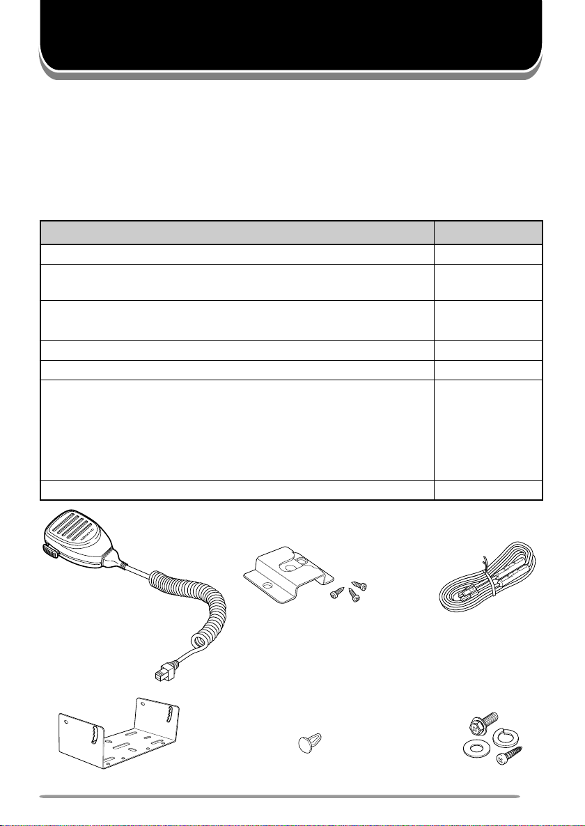
SUPPLIED ACCESSORIES
metI ytitnauQ
)ylno089-KT(
tikelbacrewopCD
)A01(esuF•
tekcarbgnitnuoM1
packcajrekaepS1
:teswercS
)seceip4(wercsgnippat-fleS•
)seceip4(rehsawgnirpS•
)seceip4(rehsawtalF•
launamnoitcurtsnI1
KENWOOD
dealer, an authorized
)ylno089-KT(elbacenohporcimdnaenohporciM1
swercsgnippat-fleshtiwregnahenohporciM
tes
1
tes1
eceip4(rehsawhtiwwercsdedaeh-xeH•
)s
tes1
Microphone and
microphone cable
(TK-980 only)
Mounting bracket
DC power cable kitMicrophone hanger
with self-tapping screws
(TK-980 only)
Screw setSpeaker jack cap
1
PREPARATION
VARIOUS ELECTRONIC EQUIPMENT IN YOUR VEHICLE MAY MALFUNCTION IF THEY ARE
NOT PROPERLY PROTECTED FROM THE RADIO FREQUENCY ENERGY WHICH IS PRESENT
WHILE TRANSMITTING. ELECTRONIC FUEL INJECTION, ANTI-SKID BRAKING, AND CRUISE
CONTROL SYSTEMS ARE TYPICAL EXAMPLES OF EQUIPMENT THAT MAY MALFUNCTION. IF
YOUR VEHICLE CONTAINS SUCH EQUIPMENT, CONSULT THE DEALER FOR THE MAKE OF
VEHICLE AND ENLIST HIS AID IN DETERMINING IF THEY WILL PERFORM NORMALLY WHILE
TRANSMITTING.
Note
: The following preparation instructions are for use by your
KENWOOD
service facility, or the factory.
TOOLS REQUIRED
Note
: Before installing the transceiver, always check how far the mounting screws will extend below the
mounting surface. When drilling mounting holes, be careful not to damage vehicle wiring or parts.
The following tools are required for installing the transceiver:
• 6 mm (1/4 inch) or larger electric drill
• Drill bits (sizes listed below) and circle cutters
eziStiBllirD esopruP
)hcni23/5(mm2.4swercsgnippat-flesmm61x5
)hcni8/1(mm2.3swercsgnippat-flesmm61x4
KENWOOD
dealer, an authorized
POWER CABLE CONNECTION
THE TRANSCEIVER OPERATES IN 12 V NEGATIVE GROUND SYSTEMS ONLY! CHECK THE
BATTERY POLARITY AND VOLTAGE OF THE VEHICLE BEFORE INSTALLING THE
TRANSCEIVER.
1
Check for an existing hole, conveniently located in the firewall, where the
power cable can be passed through.
• If no hole exists, use a circle cutter to drill the firewall, then install a rubber
grommet.
2
Run the two power cable leads through the firewall and into the engine
compartment, from the passenger compartment.
3
Connect the red lead to the positive (+) battery terminal and the black lead to
the negative (–) battery terminal.
• Locate the fuse as close to the battery as possible.
4
Recoil and secure the surplus cable with the provided retaining band.
• Be sure to leave enough slack in the cables so the transceiver can be removed for
servicing while keeping the power applied.
2
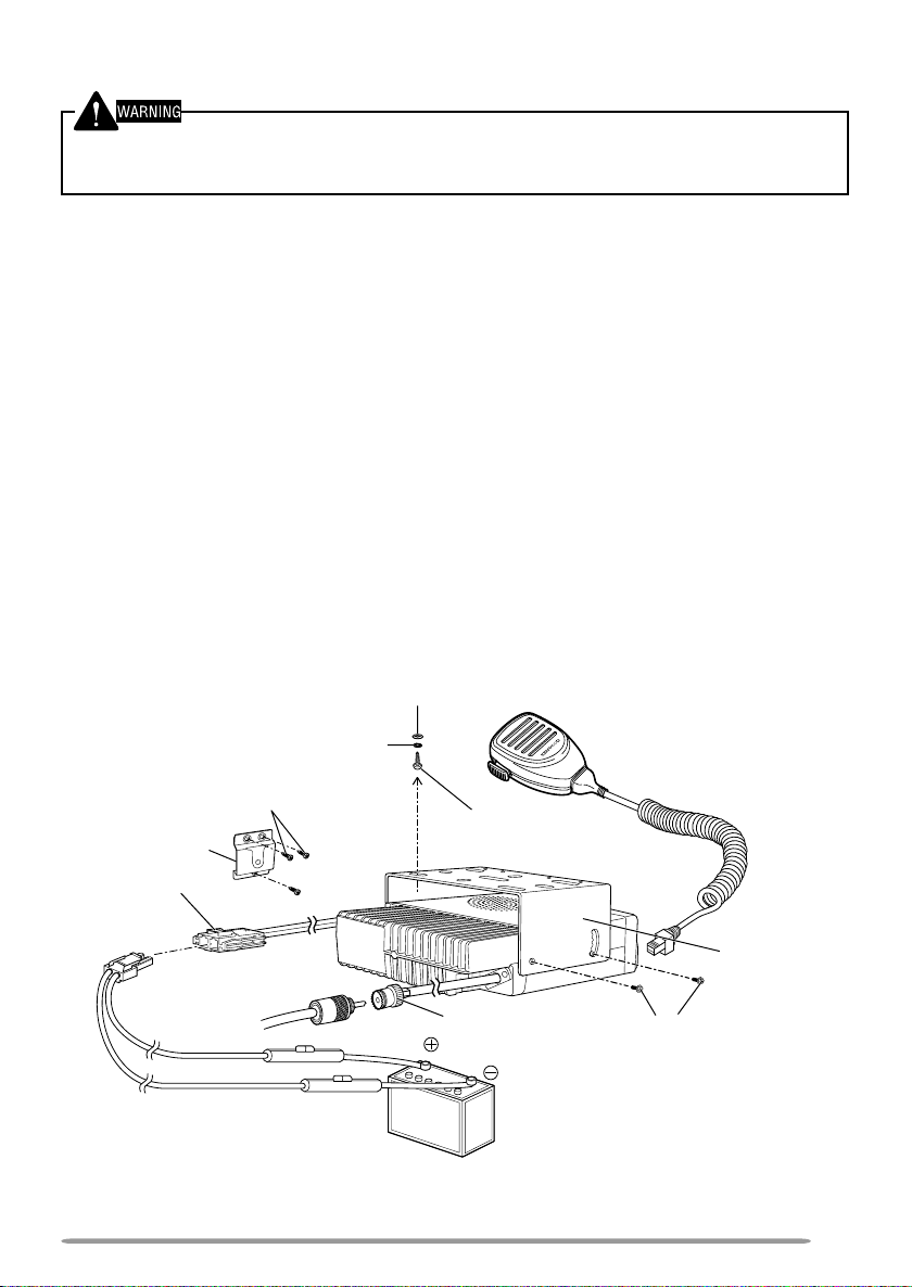
INSTALLING THE TRANSCEIVER
FOR PASSENGER SAFETY, INSTALL THE TRANSCEIVER SECURELY, USING THE SUPPLIED
MOUNTING BRACKET, SO THE TRANSCEIVER WILL NOT BREAK LOOSE IN THE EVENT OF A
COLLISION.
1 Mark the position of the holes in the dash by using the mounting bracket as a
template. Drill the holes, then attach the mounting bracket using the supplied
5 x 16 mm screws.
• Be sure to mount the transceiver in a location where the controls are within easy
reach of the user, and where there is sufficient space at the rear of the transceiver
for cable connections.
2 Connect the antenna and the supplied power cable to the transceiver.
3 Slide the transceiver into the mounting bracket and secure it using the
supplied hex-headed screws.
4 Mount the microphone hanger, using the supplied 4 x 16 mm screws, in a
location where it will be within easy reach of the user.
• The microphone and microphone cable should be mounted in a place where they
will not interfere with the safe operation of the vehicle.
TK-980 only: Connect one plug of the microphone cable to the jack on the base
of the microphone, and the other plug to the microphone jack on the front
panel of the transceiver. Place the microphone on the hanger.
Flat washer
Spring washer
4 x 16 mm self-tapping
screw (TK-980 only)
Microphone hanger
(TK-980 only)
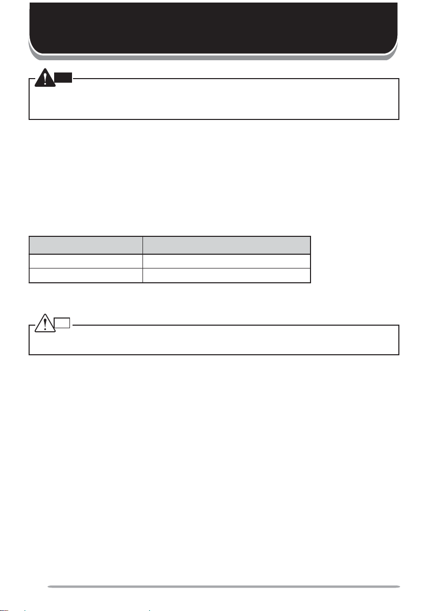
Power input
connector
DC power cable
* The above diagram shows the TK-780/ TK-880 transceiver. The antenna connector of
the TK-980 transceiver is different.
5 x 16 mm
self-tapping screw
Antenna
connector
12 V vehicle
battery
Microphone and microphone
cable (TK-980 only)
Mounting
bracket
Hex-headed screw
3
ORIENTATION
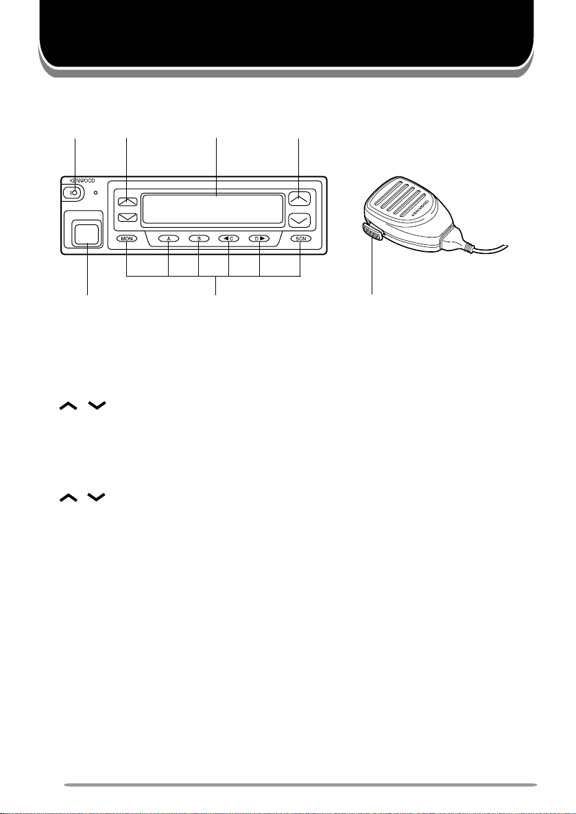
FRONT PANEL AND MICROPHONE
ww
w
tt
t
tt
ww
pp
pC, D
pp
qq
q
qq
qq
q IO (Power) switch
qq
Press to switch the transceiver ON (or OFF).
ww
w / keys
ww
Press these keys to activate their programmable auxiliary functions
{page 6}.
ee
e Display
ee
See page 5 for more information.
rr
r / keys
rr
Press these keys to activate their programmable auxiliary functions
{page 6}.
tt
t Microphone jack
tt
Insert the microphone plug into this connector.
yy
y MON, A, B,
yy
Press these keys to activate their programmable auxiliary functions
{page 6}.
uu
u PTT switch
uu
To transmit, press and hold this switch, then speak into the microphone.
Release to receive.
ee
e
ee
yy
y
yy
oo
o, and SCN keys
oo
rr
r
rr
uu
u
uu
* The microphone comes only
with the TK-980 transceiver.
4
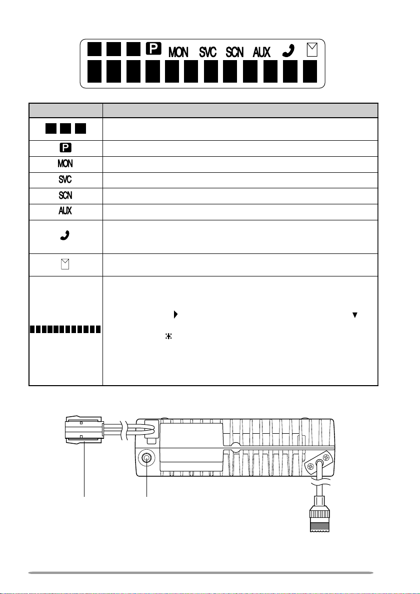
DISPLAY
rotacidnI noitpircseD
oirav
ehwsraeppA
mmargorp
ehsalF
.yromemkcatsehtniderots
)(llaCevitceleS _ dda/eteledehT.noitcnuf)
sademmargorpyekehtnehwsraeppA rotinoM .desserp
hcdna,puorg,metsysehtmargorpnac
(relbmarcSro
syalpsidoslA.srebmunlennahcdna,puorg,metsysehtsyalpsiD
.relaedruoyybdemmargorpneebevahhcihwsnoitcnufsu
.ytiroirpsademmargorpsilennahcdetcelesehtnehwsraeppA
si
.reviecsnartsihtnodesutonsinocisihT
.edomnacSgnisuerauoynehwsraeppA
.detavitcasinoitcnufyrailixuaehtn
sipuorgdetcelesehtnehwsraeppa,tamroFgniknurTnI
sraeppa,tamroFlanoitnevnoCnI.sDIenohpeletsade
.noitcnufenoTelbatceleSrotarepOehtgnisuerauoynehw
siegassemanehwsthgiL.egassemaevieceruoynehws
relaedruoY.srebmunlennahcdna,puorg,metsysehtsyalpsiD
01otpuhtiwsemanlenna
asadesusiyalpsidtsomtfelehT.srebmunfoecalpni,sretcarahc
anadnatamroFgniknurTni)(rotacidnieteled
bmarcSdnallaCevitceleS.ecneuqesgninnacsehtfotuo
.
SMDgnisunehwsegassemdeviecersyalpsid
ni)(rotacidnidd
ehtrofdesusiyalpsidtsomthgirehT.tamroFlanoitnevnoC
dekcolton/dekcoleratahtslennahc/smetsysehtwohssrotacidni
erarel
oslA.relaedruoyybdemmargorpebnactahtsnoitcnuflanoitpo
REAR PANEL
Power input
connector
* The above diagram shows the TK-780/ TK-880 transceiver. The antenna connector of
the TK-980 transceiver is different.
External
speaker jack
Antenna connector
5

PROGRAMMABLE AUXILIARY FUNCTIONS
Keys w, r, and y {page 4} can be programmed with the auxiliary functions
listed in the following table. The keys can only be programmed with functions,
depending on whether you are using Conventional Format or Trunking Format.
Please contact your dealer for further details on these functions.
Note
:
◆
If “Function” is programmed onto one of the above mentioned keys, the microphone keypad can also
be used for additional programmable keys.
◆
Only the TK-780 and TK-880 transceivers support Conventional Format.
noitcnuF
lanoitnevnoC
tamroF
leTotuAoNseY
AXUAseYseY
1
BXUA
seYseY
nwoDlennahCseYoN
pUlennahCseYoN
retcarahCyalpsiDseYseY
)TOB(DIFMTDseYseY
)TOE(DIFMTDseYseY
noitcnuFseYseY
GseYseY
nwoDpuor
pUpuorGseYseY
lennahCemoHseYoN
puorGemoHoNseY
trelAnroHseYseY
kcoLyeKseYseY
)OTS/LCR(yromeMseYseY
)LCR(yromeMseYseY
OTS(yromeMseYseY
)
edoMegasseMseYseY
))yratnemoM(etumnUrotinoM(ArotinoMseYseY
))elggoT(etumnUrotinoM(BrotinoMseYseY
))yratnemoM(hcleuqSreirraC(CrotinoMseYseY
))elggoT(hcleuqSreirraC(DrotinoMseYseY
enoTleSrotarepOseYoN
cilbuPseYseY
sserddA
gniknurT
tamroF
6

noitcnuF
lanoitnevnoC
tamroF
gniknurT
tamroF
laideRseYseY
nacSseYseY
ddA/leDnacSseYseY
eteleDyraropmeTnacSoNseY
2
relbmarcS
3
SPGdneS
seYseY
seYseY
nwoDmetsySoNseY
pUmetsySoNseY
dnuorAklaTseYoN
tcennocsiDleToNseY
nwoDemuloVseYseY
pUemuloVseYseY
1
This function can be selected only when the Scrambler/ ANI board has not been
installed.
2
This function can be selected only when the Scrambler board has been installed.
3
This function can be selected only when a GPS receiver has been installed.
The Emergency function can also be programmed. However, it can only be used
with a foot switch.
7

BASIC OPERATIONS
OPERATION OVERVIEW
■ Trunking Format
This format can handle up to 600 channels in conventional mode, and 32
systems with up to 250 groups in each system in trunking mode. Systems,
groups, channels, and their functions are programmed by your dealer.
■ Conventional Format (TK-780 and TK-880 only)
This format can handle up to 250 groups with 250 channels in each group.
The transceiver can be used only in conventional mode. Groups, channels,
and their functions are programmed by your dealer.
SWITCHING POWER ON/OFF
Press the IO switch to switch the transceiver ON (or OFF).
ADJUSTING THE VOLUME
Press the keys programmed as Volume Up and Volume Down to adjust the
volume. Volume Up increases the volume and Volume Down decreases it.
SELECTING A SYSTEM/ GROUP/ CHANNEL
Select the desired system and group (Trunking Format) using the keys
programmed with the System and Group functions.
Select the desired group and channel (Conventional Format) using the keys
programmed with the Group and Channel functions.
TIME-OUT TIMER (TOT)
The purpose of the Time-out Timer is to prevent any caller from using a channel
for an extended period of time.
If you continuously transmit for a period of time that exceeds the programmed
time, the transceiver will stop transmitting and an alert tone will sound. To stop
the tone, release the PTT switch.
Your dealer can program the TOT time in the range of 15 seconds to 10 minutes.
HORN ALERT
If Horn Alert has been installed by your dealer, your vehicle horn, or some other
type of external alert, will sound when certain calls are received. This is a useful
function when you are away from your vehicle.
8

TRUNKING FORMAT
TRUNKED OPERATION
■ Placing a Dispatch Call
1 Select the desired system and group using the System and Group keys.
2 Press the PTT switch.
3 If a tone does not sound, communication is possible; start speaking into
the microphone. Release the PTT switch to receive.
• For best sound quality at the receiving station, hold the microphone
approximately 1.5 inches (3 ~ 4 cm) from your mouth.
4 When your conversation is finished, return the microphone to its hanger.
■ Receiving a Dispatch Call
1 Select the desired system and group using the System and Group keys.
(If the Scan function has been programmed, you can switch it ON or OFF
as desired.)
2 When you hear the dispatcher’s voice, readjust the volume as necessary.
■ Placing a Telephone Call
Note:
You can make a telephone call only if the telephone service is available and you have an
optional keypad microphone. Refer to “MAKING A DTMF CALL” on page 17. Consult your dealer
for further details.
1 Select the desired system and group using the System and Group keys.
2 Press and hold the PTT switch for approximately 1 second to ensure a
connection.
• Confirm that there is a dial tone after releasing the PTT switch.
3 Dial using the microphone keypad.
• After dialing, wait for a response from the called party.
4 When the called party responds, press the PTT switch and speak into the
microphone. Release the PTT switch to receive.
• Only one person can speak at a time.
5 To end the call, press the # key or the key programmed as Tel
Disconnect.
9

■ Receiving a Telephone Call
1 Select the desired system and group using the System and Group keys.
(If the Scan function has been programmed, you can switch it ON or OFF
as desired.)
• A ringing tone will sound when a call is received.
2 Press and hold the PTT switch to speak, and release it to listen.
• Only one person can speak at a time.
3 To end the call, press the # key or the key programmed as Tel
Disconnect.
CONVENTIONAL OPERATION
■ Transmitting
Note:
Before transmitting, monitor the channel to make sure it is not already in use. If the selected
group is programmed with QT (Quiet Talk) or DQT (Digital Quiet Talk), remove the microphone from
the hook to disable QT or DQT, then listen to the channel to make sure nobody is talking on it. If the
selected group is not programmed with QT or DQT, simply listen to the channel to make sure nobody
is talking on it. In this case, you need not remove the microphone from the hook.
1 Select the desired system and group using the System and Group keys.
• If the channel is busy, wait until it becomes free.
2 Press the PTT switch and speak into the microphone. Release the PTT
switch to receive.
• For best sound quality at the receiving station, hold the microphone
approximately 1.5 inches (3 ~ 4 cm) from your mouth.
3 When your conversation is finished, return the microphone to its hanger.
■ Receiving
1 Select the desired system and group using the System and Group keys.
(If the Scan function has been programmed, you can switch it ON or OFF
as desired.)
2 When you hear the dispatcher’s voice, readjust the volume as necessary.
SYSTEM SCAN
If the Scan function is programmed, systems can be scanned by pressing the
key programmed as Scan. When the Scan key is pressed, the SCN indicator
and “-SCAN-” or the revert system/ group number, appear on the display and
scanning starts. The systems not locked out of the scanning sequence are
scanned.
When a call is received, scanning stops and the system and group digits appear.
Press the PTT switch and speak into the microphone to respond to the call. The
transceiver will continue scanning after an adjustable time delay if the PTT
switch is released and no further signal is received.
10

■ Scanning Trunked Systems
When scanning trunked systems, the revert groups and the groups not locked
out of the scanning sequence are scanned. See “GROUP SCAN”, below.
■ Scanning Conventional Systems
When scanning conventional systems, the revert groups and the groups not
locked out of the scanning sequence are scanned. See “GROUP SCAN”,
below.
Scan Lockout
■
If a programmable auxiliary key is programmed with Scan Del/Add, each
system can be locked out of the scan sequence manually. The delete
indicator (
out.
■ Scan Revert
You can select revert systems and groups using the System and Group
keys.
Three types of Scan Reverts which can be programmed by your dealer are
available:
• Last Called Revert: The last system/ group received is assigned as the
new revert system and group.
• Last Used Revert: The last system/ group responded to is assigned as
the new revert system and group.
• Selected: The last system/ group selected is assigned as the new revert
system and group.
oo
o) will appear in the display when the selected system is locked
oo
GROUP SCAN
Group Scan is available for both trunked and conventional systems. This feature
is useful when more than one group is programmed in a system. Group Scan is
set by your dealer on request. It scans the revert groups as well as groups that
are allowed to be scanned.
When a call is received, the group indicator shows the group number, and that
group becomes the revert group. Simply press the PTT switch to respond to the
call.
You can also perform Group Scan while using a priority channel. Please contact
your dealer for information concerning Priority Scan.
11

CONVENTIONAL FORMAT (TK-780 and TK-880 only)
CONVENTIONAL OPERATION
■ Transmitting
Note:
Before transmitting, monitor the channel to make sure it is not already in use. If the selected
channel is programmed with QT (Quiet Talk) or DQT (Digital Quiet Talk), remove the microphone
from the hook to disable QT or DQT, then listen to the channel to make sure nobody is talking on it.
If the selected channel is not programmed with QT or DQT, simply listen to the channel to make sure
nobody is talking on it; in this case, you need not remove the microphone from the hook.
1
Select the desired group and channel using the
• If the channel is busy, wait until it becomes free.
2
Press the
PTT
switch and speak into the microphone. Release the
switch to receive.
• For best sound quality at the receiving station, hold the microphone
approximately 1.5 inches (3 ~ 4 cm) from your mouth.
3
When your conversation is finished, return the microphone to its hanger.
■ Receiving
1
Select the desired group and channel using the
(If the Scan function has been programmed, you can switch it ON or OFF
as desired.)
2
When you hear the dispatcher’s voice, readjust the volume as necessary.
Group
Group
and
and
Channel
Channel
keys.
PTT
keys.
12

SCAN
If the Scan function is programmed, groups or channels can be scanned by
pressing the key programmed as Scan. Scan can be used as either Single Scan
or Multi Scan. Single Scan monitors only the channels of a single group. Multi
Scan monitors all channels of every group. When the Scan key is pressed, the
SCN indicator and “-SCAN-” or the revert group/ channel number, appear on the
display and scanning starts.
When a call is received, scanning stops and the group and channel digits
appear. Press the PTT switch and speak into the microphone to respond to the
call. The transceiver will continue scanning after an adjustable time delay, if the
PTT switch is released, and no further signal is received.
When the displayed group is not locked out of the scanning sequence, the add
indicator ( ) will appear on the display.
■ Priority Scan
The priority channel must be programmed in order for Priority Scan to
function.
The transceiver will automatically change to the priority channel when a signal
is received on it, even if a signal is being received on a normal channel.
The indicator appears when the displayed channel is the priority channel.
2-TONE SIGNALLING
2-Tone Signalling is either activated or deactivated by your dealer.
2-Tone Signalling only opens the squelch when the transceiver receives two
tones corresponding to those set up in the transceiver. When the squelch opens,
you will be able to hear the caller without any further action.
After a correct 2-Tone signal is received and the squelch opens, pressing the key
programmed as Monitor will cancel the connection.
If your dealer programmed Transpond for 2-Tone Signalling, your transceiver will
automatically send an acknowledgment signal to the station that called you with
a correct 2-Tone signal. Transpond does not function when you are called as a
Group call.
If your dealer programmed Tone Alert for 2-Tone Signalling, your transceiver will
emit a beep when the correct 2-Tone signal is received.
Note:
This transceiver is only capable of decoding 2-Tone Signals. It cannot encode a 2-Tone Signal.
13

FleetSync: ALPHANUMERIC TWO-WAY PAGING FUNCTION
FleetSync is an Alphanumeric Two-way Paging Function, and is a protocol owned by
JVC KENWOOD Corporation. FleetSync enables a variety of paging functions on
your transceiver, some of which depend on dealer programming.
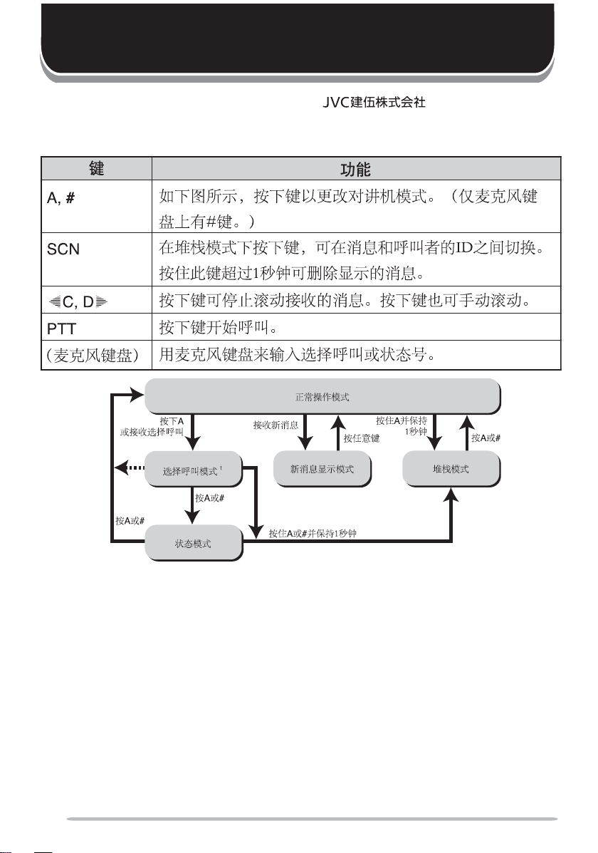
KEY FUNCTIONS
yeK noitcnuF
A, #
NCS
pppppC, Dooooo
TTP .llacaetaitiniotsserP
)dapyeK
ehT(.woleb # ).ylnosdapyekenohporcimnoelba
liavasiyek
gassem
.egassemdeyalpsidehteteledotdnoces1
tsserP
.yllaunamllorcs
enohporciM(
ohporcimehtesU
Normal Operating Mode
margaidehtninwohssaedomreviecsnartehtegnahcotsserP
deviecerehtneewtebelggototedoMkcatSnielihwsserP
nahteromrofdlohdnasserP.DIs’rellacehtdnae
otsserposlA.segassemdeviecergnillorcs-otuapotso
.srebmunsutatSrollacleSretneotdapyeken
Press A
or receive
a Selcall
Selcall Mode
Press
A
or
Press
A
or
#
Status Mode
1
Depending on how your dealer programmed the transceiver, Selcall Mode may be skipped
Receive
a new
message
1
#
New Message
Display Mode
Hold A or # for 1 second
Press
any key
A
for
Hold
1 second
Stack Mode
Press
A
or
#
or the transceiver may exit Selcall Mode automatically (as shown by the dash arrow).
SHORT MESSAGES FEATURE
Received short messages (maximum of 48 characters) are displayed the same
as Status messages {page 15}, however only 4 short messages can be stored in
the stack memory. “M” (Message) and the message number appear with the
message.
GPS REPORT
If a GPS unit (NMEA-0183 format) is installed on the transceiver and the Send
GPS function is programmed onto a key by your dealer, you can press the
programmed key to send your location data.
14

SELCALL (SELECTIVE CALLING)
A Selcall is a voice call to a particular station or to a group of stations.
■ Transmitting
1 Select your desired system and group (or group and channel).
2 Press the A key to enter Selcall Mode.
3 Use the / keys (right side keys only) to select the ID of the station
you want to call.
• You can also enter digits by using the microphone keypad if Manual Dial is
enabled. (Press
4 Press the PTT switch and begin your conversation.
■ Receiving
An alert tone will sound, the transceiver will automatically enter Selcall Mode,
and the calling station’s ID will appear when a Selcall is received.
To respond to the call, press the PTT switch and speak into the microphone.
■ Identification Codes
An ID code is a combination of a 3-digit Fleet number and a 4-digit ID
number. Each transceiver must have its own Fleet and ID number.
• Enter a Fleet number (100 ~ 349) to make a group call.
• Enter an ID number (1000 ~ 4999) to make an individual call in your fleet.
• Enter a Fleet number followed by an ID number to make an individual call
in your desired fleet (Inter-fleet call).
• Select “ALL” Fleet and “ALL” ID to make a call to all units (Broadcast call).
• Select “ALL” Fleet and enter an ID number to make a call to the selected
ID in all fleets (Supervisor call).
Note:
◆
Broadcast and Supervisor calls are programmed functions that cannot be made with a keypad.
◆
The ID range may be limited by programming.
to erase an incorrect digit.)
STATUS MESSAGE
You can send and receive 2-digit Status messages (10 ~ 79) which may be decided
in your talk group. Messages can contain up to 16 alphanumeric characters.
A maximum of 9 received messages can be stored in the stack memory of your
transceiver. These saved messages can be reviewed after reception. If the
stack memory is full, the oldest message will be erased when a new message is
received. The mail icon ( ) lights when a message is stored in the stack
memory.
Note:
All stored messages will be cleared when the transceiver power is turned OFF.
15

■ Transmitting
1 Select your desired system and group (or group and channel).
2 Press the A key to enter Selcall Mode.
3 Use the / keys (right side keys only) to select the ID of the station
you want to call.
• You can also enter digits by using the microphone keypad if Manual Dial is
enabled. (Press
to erase an incorrect digit.)
4 Press the A or # key to enter Status Mode.
5 Use the / keys (right side keys only) to select the status you want to
transmit.
• You can also enter digits by using the microphone keypad if Manual Dial is
enabled. (Press
to erase an incorrect digit.)
6 Press the PTT switch to initiate the Status call.
• “COMPLETE” is displayed when the call has been successfully transmitted.
■ Receiving
The mail icon ( ) will flash and a calling ID or text message will appear
when a Status call is received.
• The display alternates between the caller ID and the message.
Press any key to return to Normal Operation Mode.
■ Reviewing Messages in the Stack Memory
1 Press and hold the A key for more than 1 second to enter Stack Mode.
• The last received message is displayed with the message number. “S” (Status)
appears with the number.
2 Use the / keys (right side keys only) to select the message you
want to view (if more than one message is stored in the stack memory).
3 Press the
pp
pC or D
pp
oo
o key to stop the message from auto-scrolling if
oo
desired. Also use these keys to scroll through the message manually.
4 Press the SCN key to toggle between the message and the caller’s ID.
5 To erase the message, press and hold the SCN key for more than
1 second.
■ Automatic Status Response
If you pre-select a status number and then leave the transceiver in Status
Mode, the transceiver will automatically respond with that status number
when a request from the base station is received. (The base station request
function is optional.)
16

DTMF (DUAL TONE MULTI FREQUENCY) CALLS
MAKING A DTMF CALL
Note:
To make a DTMF call, you must have an optional microphone with a DTMF keypad. Ask your
dealer for more information.
There are two methods of making a DTMF call:
• Manual dialing
• Store and sending
To make a call by dialing manually:
1
Press and hold the
2
Enter the desired digits using the microphone keypad.
• The corresponding DTMF tones sound each time you press a key.
• If you release the
has not been sent.
• If your dealer has activated the Keypad Auto PTT function, you need not hold down
the
PTT
switch while pressing the keys on the keypad. The DTMF code will be
sent automatically when you press a key.
To make a call by storing and sending:
1
Enter the desired digits using the microphone keypad.
• The digits appear on the display as you enter them.
2
After entering the complete number, press the
• If you are using the transceiver in a Conventional mode and Format, the DTMF
code is transmitted after pressing the
• If you are using the transceiver in a Trunking system, the DTMF code is transmitted
after a connection is established. Releasing the
established will stop the transmission from occuring.
• If you are using the transceiver in a RIC (Repeater Inter-Connect) Trunking system,
the DTMF code is transmitted after a connection with the telephone system is
established. If you press the key programmed as
switch, the call will automatically connect to the repeater, and the DTMF code will
be transmitted.
Note:
◆
Store and send must first be activated by your dealer in order for it to function.
◆
You can only store up to 16 digits before sending. Entering more than 16 digits will cause an error
tone to sound.
◆
In store and sending mode, if you switch the power OFF before sending the number, the number will
be cleared from memory.
PTT
switch.
PTT
switch, transmit mode will end even if the complete number
PTT
switch.
PTT
switch.
PTT
switch before a connection is
Auto Tel
instead of the
PTT
17

DTMF SIGNALLING
Your dealer can program a group or channel with DTMF signalling. When you
receive a call with a code that matches yours, the signalling indicator ( ) will
flash and a tone will sound. Squelch opens and you will hear the call.
Squelch will close when you receive a call with a code that matches your
signalling reset code.
When making a call on a group or channel programmed with a DTMF signalling
code, the signalling indicator will light and the squelch will open.
If your dealer programmed Transpond for DTMF signalling, your transceiver will
automatically send an acknowledgment signal to the station that called you with
the correct DTMF code.
DBD (DEAD BEAT DISABLE)
Depending on how your dealer programs your transceiver, when you receive a
call containing a DBD code, either transmit mode or receive and transmit modes
will be disabled. When a DBD code is received, a tone will sound.
DBD is cancelled when you receive a call with a DBD cancel code.
18

AUDIBLE USER FEEDBACK TONES
The transceiver emits various tones to indicate the transceiver’s operating status.
Please contact your dealer for further information on these tones.
Note
: Only the TK-780 and TK-880 transceivers support the tone for Conventional Format.
enoT
trelAseYseY
ysuBseYseY
nODBDseYseY
ffODBDseYseY
yaleDoNseY
yneDoNseY
erFoNseY
llaCpuorGseYseY
llaClaudividnIseYseY
tpecretnIoNseY
rorrEtupnIyeKseYseY
]A[sserPyeKseYseY
]B[sserPyeKseYseY
erPyeKseYseY
]C[ss
tnemeergAdrowssaPseYseY
NOrewoPseYseY
trelAerPseYoN
deecorPoNseY
esaeleRTTPseYseY
eueuQoNseY
gnigniRoNseY
oRseYseY
revOll
hcraeSmetsySoNseY
dnEhcraeSmetsySoNseY
dnopsnarTseYseY
edoMhcraeSmetsyS/edoMkcaBgniRmetsySe
lanoitnevnoC
tamroF
gniknurT
tamroF
19

!"
VHF !"#$
TK-780
UHF !"#$
TK-880
800MHz !"#$
TK-980

!"KENWOOD !"#$%&'()* +,-.)/012!3
!"#$%&'()*+,(-%./0123456
KENWOOD !"#$%&'()*+,-./01234567&89:
!"#$
!
!"#$%&'(!)*+,-./012345+6789:;
• !"#$%&'()*+,-./
• !"#$%&'()*
• !"#$%&'()*+,-./0 123456789:
• !"#$%&'()*+,-./0123456/789:
• !"#$%&'()*+,-./0123,45KENWOOD !"#
!"#
◆ !"#$%&'()*+,-./012'3456789
◆ !"#$%&'()*+(,-./0
◆ !"#$%&'()*+,-
! !"#$%&'()*+,-./01
◆ !"#$#%&'(&)*+,
!"#$%&'()*+,-.)*+/0!1234567&8!9$:123;
!"#$%&
◆ !"#
!"#$%&'(#$OP !"#$%&'()*+,-.'/0123 456
!"#$%&
◆ !
!"#RMM !"#$%&'()*+,-./0123
!"#$%&'()*+,-./012345$6789,-:;<=>?@$A
!"#$%&'(#$) *+,-./0123456*+78#$)9:;%<=:
!"#$%&'()*

!"#$%&' KKKKKKKKKKKKKKKKKKKKKKKKKKKKKKKKKKKKKKKKKKKKKKKKKKKKKKKKKKKKKKKKKKKKKKKKKKKKKKKKKKKKKKKKKKKKKKKKKKKKKKKKKKKKKKK 1
!" KKKKKKKKKKKKKKKKKKKKKKKKKKKKKKKKKKKKKKKKKKKKKKKKKKKKKKKKKKKKKKKKKKKKKKKKKKKKKKKKKKKKKKKKKKKKKKKKKKKKKKKKKKKKKKKKKKKKKKKKKKKKKKK 1
KKKKKKKKKKKKKKKKKKKKKKKKKKKKKKKKKKKKKKKKKKKKKKKKKKKKKKKKKKKKKKKKKKKKKKKKKKKKKKKKKKKKKKKKKKKKKKKKKKKKKKKKKKKKKKKKKKKKKKKKKKKKKKKKKKKKKKKKKKKKKKKKKKKKK 2
!" KKKKKKKKKKKKKKKKKKKKKKKKKKKKKKKKKKKKKKKKKKKKKKKKKKKKKKKKKKKKKKKKKKKKKKKKKKKKKKKKKKKKKKKKKKKKKKKKKKKKKKKKKKKKKKKKKKKKKKKKKKKKKKK 2
!"# KKKKKKKKKKKKKKKKKKKKKKKKKKKKKKKKKKKKKKKKKKKKKKKKKKKKKKKKKKKKKKKKKKKKKKKKKKKKKKKKKKKKKKKKKKKKKKKKKKKKKKKKKKKKKKKKKKKKKKKKKK 2
!" KKKKKKKKKKKKKKKKKKKKKKKKKKKKKKKKKKKKKKKKKKKKKKKKKKKKKKKKKKKKKKKKKKKKKKKKKKKKKKKKKKKKKKKKKKKKKKKKKKKKKKKKKKKKKKKKKKKKKKKKKKKKKKK 3
KKKKKKKKKKKKKKKKKKKKKKKKKKKKKKKKKKKKKKKKKKKKKKKKKKKKKKKKKKKKKKKKKKKKKKKKKKKKKKKKKKKKKKKKKKKKKKKKKKKKKKKKKKKKKKKKKKKKKKKKKKKKKKKKKKKKKKKKKKKKKKKKKKKKK 4
!"#$ KKKKKKKKKKKKKKKKKKKKKKKKKKKKKKKKKKKKKKKKKKKKKKKKKKKKKKKKKKKKKKKKKKKKKKKKKKKKKKKKKKKKKKKKKKKKKKKKKKKKKKKKKKKKKKKKKKKKK 4
KKKKKKKKKKKKKKKKKKKKKKKKKKKKKKKKKKKKKKKKKKKKKKKKKKKKKKKKKKKKKKKKKKKKKKKKKKKKKKKKKKKKKKKKKKKKKKKKKKKKKKKKKKKKKKKKKKKKKKKKKKKKKKKKKKKKKKKK 5
KKKKKKKKKKKKKKKKKKKKKKKKKKKKKKKKKKKKKKKKKKKKKKKKKKKKKKKKKKKKKKKKKKKKKKKKKKKKKKKKKKKKKKKKKKKKKKKKKKKKKKKKKKKKKKKKKKKKKKKKKKKKKKKKKKKKKKKK 5
!" KKKKKKKKKKKKKKKKKKKKKKKKKKKKKKKKKKKKKKKKKKKKKKKKKKKKKKKKKKKKKKKKKKKKKKKKKKKKKKKKKKKKKKKKKKKKKKKKKKKKKKKKKKKKKKKKKKKKKKKKKKKKKKKKKKKKKK 6
! KKKKKKKKKKKKKKKKKKKKKKKKKKKKKKKKKKKKKKKKKKKKKKKKKKKKKKKKKKKKKKKKKKKKKKKKKKKKKKKKKKKKKKKKKKKKKKKKKKKKKKKKKKKKKKKKKKKKKKKKKKKKKKKKKKKKKKKKKKK 8
! KKKKKKKKKKKKKKKKKKKKKKKKKKKKKKKKKKKKKKKKKKKKKKKKKKKKKKKKKKKKKKKKKKKKKKKKKKKKKKKKKKKKKKKKKKKKKKKKKKKKKKKKKKKKKKKKKKKKKKKKKKKKKKKKKKKK 8
! KKKKKKKKKKKKKKKKKKKKKKKKKKKKKKKKKKKKKKKKKKKKKKKKKKKKKKKKKKKKKKKKKKKKKKKKKKKKKKKKKKKKKKKKKKKKKKKKKKKKKKKKKKKKKKKKKKKKKKKKKKKK 8
!"#$qK-780TK-880 KKKKKKKKKKKKKKKKKKKKKKKKKKKKKKKKKKKKKKKKKKKKKKKKKKKKKKKKKKKKKKKKKKKKK 8
L ! KKKKKKKKKKKKKKKKKKKKKKKKKKKKKKKKKKKKKKKKKKKKKKKKKKKKKKKKKKKKKKKKKKKKKKKKKKKKKKKKKKKKKKKKKKKKKKKKKKKKKKKKKKKKKKKKKKKKKKKK 8
! KKKKKKKKKKKKKKKKKKKKKKKKKKKKKKKKKKKKKKKKKKKKKKKKKKKKKKKKKKKKKKKKKKKKKKKKKKKKKKKKKKKKKKKKKKKKKKKKKKKKKKKKKKKKKKKKKKKKKKKKKKKKKKKKKKKK 8
!LL KKKKKKKKKKKKKKKKKKKKKKKKKKKKKKKKKKKKKKKKKKKKKKKKKKKKKKKKKKKKKKKKKKKKKKKKKKKKKKKKKKKKKKKKKKKKKKKKKKKKKKKKKKKKKKKK 8
!TOT KKKKKKKKKKKKKKKKKKKKKKKKKKKKKKKKKKKKKKKKKKKKKKKKKKKKKKKKKKKKKKKKKKKKKKKKKKKKKKKKKKKKKKKKKKKKKKKKKKKKKKKKKKKK 8
! KKKKKKKKKKKKKKKKKKKKKKKKKKKKKKKKKKKKKKKKKKKKKKKKKKKKKKKKKKKKKKKKKKKKKKKKKKKKKKKKKKKKKKKKKKKKKKKKKKKKKKKKKKKKKKKKKKKKKKKKKKKKKKKKKKKK 8
! KKKKKKKKKKKKKKKKKKKKKKKKKKKKKKKKKKKKKKKKKKKKKKKKKKKKKKKKKKKKKKKKKKKKKKKKKKKKKKKKKKKKKKKKKKKKKKKKKKKKKKKKKKKKKKKKKKKKKKKKKKKKKKKKKKKKKKKKKKK 9
! KKKKKKKKKKKKKKKKKKKKKKKKKKKKKKKKKKKKKKKKKKKKKKKKKKKKKKKKKKKKKKKKKKKKKKKKKKKKKKKKKKKKKKKKKKKKKKKKKKKKKKKKKKKKKKKKKKKKKKKKKKKKKKKKKKKK 9
!"# KKKKKKKKKKKKKKKKKKKKKKKKKKKKKKKKKKKKKKKKKKKKKKKKKKKKKKKKKKKKKKKKKKKKKKKKKKKKKKKKKKKKKKKKKKKKKKKKKKKKKKKKKKKKKKKKKKK 9
!"# KKKKKKKKKKKKKKKKKKKKKKKKKKKKKKKKKKKKKKKKKKKKKKKKKKKKKKKKKKKKKKKKKKKKKKKKKKKKKKKKKKKKKKKKKKKKKKKKKKKKKKKKKKKKKKKKKKK 9
!"# KKKKKKKKKKKKKKKKKKKKKKKKKKKKKKKKKKKKKKKKKKKKKKKKKKKKKKKKKKKKKKKKKKKKKKKKKKKKKKKKKKKKKKKKKKKKKKKKKKKKKKKKKKKKKKKKKKK 9
!"#
! KKKKKKKKKKKKKKKKKKKKKKKKKKKKKKKKKKKKKKKKKKKKKKKKKKKKKKKKKKKKKKKKKKKKKKKKKKKKKKKKKKKKKKKKKKKKKKKKKKKKKKKKKKKKKKKKKKKKKKKKKKKKKKKKK 10
KKKKKKKKKKKKKKKKKKKKKKKKKKKKKKKKKKKKKKKKKKKKKKKKKKKKKKKKKKKKKKKKKKKKKKKKKKKKKKKKKKKKKKKKKKKKKKKKKKKKKKKKKKKKKKKKKKKKKKKKKKKKKKKKKKK 10
KKKKKKKKKKKKKKKKKKKKKKKKKKKKKKKKKKKKKKKKKKKKKKKKKKKKKKKKKKKKKKKKKKKKKKKKKKKKKKKKKKKKKKKKKKKKKKKKKKKKKKKKKKKKKKKKKKKKKKKKKKKKKKKKKKK 10
! KKKKKKKKKKKKKKKKKKKKKKKKKKKKKKKKKKKKKKKKKKKKKKKKKKKKKKKKKKKKKKKKKKKKKKKKKKKKKKKKKKKKKKKKKKKKKKKKKKKKKKKKKKKKKKKKKKKKKKKKKKKKKKKKK 10
!"# KKKKKKKKKKKKKKKKKKKKKKKKKKKKKKKKKKKKKKKKKKKKKKKKKKKKKKKKKKKKKKKKKKKKKKKKKKKKKKKKKKKKKKKKKKKKKKKKKKKKKKKKKKKKKKKKK 11
!"# KKKKKKKKKKKKKKKKKKKKKKKKKKKKKKKKKKKKKKKKKKKKKKKKKKKKKKKKKKKKKKKKKKKKKKKKKKKKKKKKKKKKKKKKKKKKKKKKKKKKKKKKKKKKKKKKK 11
! KKKKKKKKKKKKKKKKKKKKKKKKKKKKKKKKKKKKKKKKKKKKKKKKKKKKKKKKKKKKKKKKKKKKKKKKKKKKKKKKKKKKKKKKKKKKKKKKKKKKKKKKKKKKKKKKKKKKKKKKKK 11
! KKKKKKKKKKKKKKKKKKKKKKKKKKKKKKKKKKKKKKKKKKKKKKKKKKKKKKKKKKKKKKKKKKKKKKKKKKKKKKKKKKKKKKKKKKKKKKKKKKKKKKKKKKKKKKKKKKKKKKKKKK 11
KKKKKKKKKKKKKKKKKKKKKKKKKKKKKKKKKKKKKKKKKKKKKKKKKKKKKKKKKKKKKKKKKKKKKKKKKKKKKKKKKKKKKKKKKKKKKKKKKKKKKKKKKKKKKKKKKKKKKKKKKKKKKKKKKKKKKK 11
KKKKKKKKKKKKKKKKKKKKKKKKKKKKKKKKKKKKKKKKKKKKKKKKKKKKKKKKKKKKKKKKKKKKKKKKKKKKKKKKKKKKKKKKKKKKKKKKKKKKKKKKKKKKKKKK 10
i

!"#$TK-780TK-880 KKKKKKKKKKKKKKKKKKKKKKKKKKKKKKKKKKKKKKKKKKKKKKKKKKKKKKKKKKKKKKKKKKKKKKKKKKKKKKKKK 12
! KKKKKKKKKKKKKKKKKKKKKKKKKKKKKKKKKKKKKKKKKKKKKKKKKKKKKKKKKKKKKKKKKKKKKKKKKKKKKKKKKKKKKKKKKKKKKKKKKKKKKKKKKKKKKKKKKKKKKKKKKKKKKKKKK 12
KKKKKKKKKKKKKKKKKKKKKKKKKKKKKKKKKKKKKKKKKKKKKKKKKKKKKKKKKKKKKKKKKKKKKKKKKKKKKKKKKKKKKKKKKKKKKKKKKKKKKKKKKKKKKKKKKKKKKKKKKKKKKKKKKKK 12
KKKKKKKKKKKKKKKKKKKKKKKKKKKKKKKKKKKKKKKKKKKKKKKKKKKKKKKKKKKKKKKKKKKKKKKKKKKKKKKKKKKKKKKKKKKKKKKKKKKKKKKKKKKKKKKKKKKKKKKKKKKKKKKKKKK 12
KKKKKKKKKKKKKKKKKKKKKKKKKKKKKKKKKKKKKKKKKKKKKKKKKKKKKKKKKKKKKKKKKKKKKKKKKKKKKKKKKKKKKKKKKKKKKKKKKKKKKKKKKKKKKKKKKKKKKKKKKKKKKKKKKKKKKKKKKK 13
! KKKKKKKKKKKKKKKKKKKKKKKKKKKKKKKKKKKKKKKKKKKKKKKKKKKKKKKKKKKKKKKKKKKKKKKKKKKKKKKKKKKKKKKKKKKKKKKKKKKKKKKKKKKKKKKKKKKKKKKKK 13
2J KKKKKKKKKKKKKKKKKKKKKKKKKKKKKKKKKKKKKKKKKKKKKKKKKKKKKKKKKKKKKKKKKKKKKKKKKKKKKKKKKKKKKKKKKKKKKKKKKKKKKKKKKKKKKKKKKKKKKKKKKKKKKKKK 13
FleetSync !"#$%&' KKKKKKKKKKKKKKKKKKKKKKKKKKKKKKKKKKKKKKKKKKKKKKKKKKKKKKKKKKKKKKKKKKKKKKKKKKKKKKKKKK 14
! KKKKKKKKKKKKKKKKKKKKKKKKKKKKKKKKKKKKKKKKKKKKKKKKKKKKKKKKKKKKKKKKKKKKKKKKKKKKKKKKKKKKKKKKKKKKKKKKKKKKKKKKKKKKKKKKKKKKKKKKKKKKKKKKK 14
!" KKKKKKKKKKKKKKKKKKKKKKKKKKKKKKKKKKKKKKKKKKKKKKKKKKKKKKKKKKKKKKKKKKKKKKKKKKKKKKKKKKKKKKKKKKKKKKKKKKKKKKKKKKKKKKKKKKKKKKKKKKKK 14
GPS KKKKKKKKKKKKKKKKKKKKKKKKKKKKKKKKKKKKKKKKKKKKKKKKKKKKKKKKKKKKKKKKKKKKKKKKKKKKKKKKKKKKKKKKKKKKKKKKKKKKKKKKKKKKKKKKKKKKKKKKKKKKKKKK 14
! KKKKKKKKKKKKKKKKKKKKKKKKKKKKKKKKKKKKKKKKKKKKKKKKKKKKKKKKKKKKKKKKKKKKKKKKKKKKKKKKKKKKKKKKKKKKKKKKKKKKKKKKKKKKKKKKKKKKKKKKKKKKKKKKK 15
KKKKKKKKKKKKKKKKKKKKKKKKKKKKKKKKKKKKKKKKKKKKKKKKKKKKKKKKKKKKKKKKKKKKKKKKKKKKKKKKKKKKKKKKKKKKKKKKKKKKKKKKKKKKKKKKKKKKKKKKKKKKKKKKKKK 15
KKKKKKKKKKKKKKKKKKKKKKKKKKKKKKKKKKKKKKKKKKKKKKKKKKKKKKKKKKKKKKKKKKKKKKKKKKKKKKKKKKKKKKKKKKKKKKKKKKKKKKKKKKKKKKKKKKKKKKKKKKKKKKKKKKK 15
KKKKKKKKKKKKKKKKKKKKKKKKKKKKKKKKKKKKKKKKKKKKKKKKKKKKKKKKKKKKKKKKKKKKKKKKKKKKKKKKKKKKKKKKKKKKKKKKKKKKKKKKKKKKKKKKKKKKKKKKKKKKKK 15
! KKKKKKKKKKKKKKKKKKKKKKKKKKKKKKKKKKKKKKKKKKKKKKKKKKKKKKKKKKKKKKKKKKKKKKKKKKKKKKKKKKKKKKKKKKKKKKKKKKKKKKKKKKKKKKKKKKKKKKKKKKKKKKKKK 15
KKKKKKKKKKKKKKKKKKKKKKKKKKKKKKKKKKKKKKKKKKKKKKKKKKKKKKKKKKKKKKKKKKKKKKKKKKKKKKKKKKKKKKKKKKKKKKKKKKKKKKKKKKKKKKKKKKKKKKKKKKKKKKKKKKK 16
KKKKKKKKKKKKKKKKKKKKKKKKKKKKKKKKKKKKKKKKKKKKKKKKKKKKKKKKKKKKKKKKKKKKKKKKKKKKKKKKKKKKKKKKKKKKKKKKKKKKKKKKKKKKKKKKKKKKKKKKKKKKKKKKKKK 16
!"#$%&'( KKKKKKKKKKKKKKKKKKKKKKKKKKKKKKKKKKKKKKKKKKKKKKKKKKKKKKKKKKKKKKKKKKKKKKKKKKKKKKKKKKKKKKKK 16
!"# KKKKKKKKKKKKKKKKKKKKKKKKKKKKKKKKKKKKKKKKKKKKKKKKKKKKKKKKKKKKKKKKKKKKKKKKKKKKKKKKKKKKKKKKKKKKKKKKKKKKKKKKKKKKKKKK 16
DTMF !"#$% KKKKKKKKKKKKKKKKKKKKKKKKKKKKKKKKKKKKKKKKKKKKKKKKKKKKKKKKKKKKKKKKKKKKKKKKKKKKKKKKKKKKKKKKKKKKKKKKKKKKKKKK 17
DTMF KKKKKKKKKKKKKKKKKKKKKKKKKKKKKKKKKKKKKKKKKKKKKKKKKKKKKKKKKKKKKKKKKKKKKKKKKKKKKKKKKKKKKKKKKKKKKKKKKKKKKKKKKKKKKKKKKKK 17
DTMF KKKKKKKKKKKKKKKKKKKKKKKKKKKKKKKKKKKKKKKKKKKKKKKKKKKKKKKKKKKKKKKKKKKKKKKKKKKKKKKKKKKKKKKKKKKKKKKKKKKKKKKKKKKKKKKKKKKKKKKKKKKKK 18
DBD ! KKKKKKKKKKKKKKKKKKKKKKKKKKKKKKKKKKKKKKKKKKKKKKKKKKKKKKKKKKKKKKKKKKKKKKKKKKKKKKKKKKKKKKKKKKKKKKKKKKKKKKKKKKKKKKKKKKKKKKK 18
!"#$%& KKKKKKKKKKKKKKKKKKKKKKKKKKKKKKKKKKKKKKKKKKKKKKKKKKKKKKKKKKKKKKKKKKKKKKKKKKKKKKKKKKKKKKKKKKKKKKKKKKKKKKKKKKKKKKKK 19
ii

!"#$%&'
!"#$%&KENWOOD !"#$KENWOOD !"#$%
!"#$%&'()*+&',-./0123456789%:;(<=
!"#$%&'()*+,-./01%234567
!"
! "#
qhJVUM
!
!"#$%&'
qhJVUM
a`
!"#
1
准备
警告
汽车中的各种电子设备,如果不能正常防护射频能量,那么在发射射频时它们可能会出现故障。电子燃
油喷射、防抱死制动装置和巡航控制系统是可能出现故障的典型设备。如果您的汽车配备以上的设备,
请与汽车制造商联系,向其咨询以确定发射射频时这些设备能否正常工作。
注:下列准备说明仅用于KENWOOD经销商、授权的KENWOOD维修机构或工厂。
所需的工具
注:在安装对讲机之前,一定要检查安装螺丝能进入安装表面的深度。钻安装孔时要小心,不要损坏汽车
的电线或零件。
安装对讲机时需要以下工具:
•6 mm(1/4英寸)或更大的电钻
• 钻头(尺寸如下)和圆形切割器
钻头尺寸
4.2 mm(5/32英寸)
3.2 mm(1/8英寸)
5 × 16 mm自攻螺丝
4 × 16 mm自攻螺丝
用途
电源线的连接
注意
本对讲机只能工作于12 V负极接地的电气系统!安装对讲机前先检查汽车蓄电池的极性和电压。
1 请检查防火隔板上是否有可以穿过电源线的现成的孔。
• 如果没有现成的孔,请使用圆形切割器在防火隔板上钻一个孔,然后安装橡胶垫圈。
2 将两根电源线从乘客室穿过防火隔板进入发动机舱。
3 将红色的导线接在蓄电池的正极(+)端子,黑色导线接在蓄电池的负极(-)
端子。
• 使保险丝尽可能地靠近蓄电池。
4 将多余的电缆重新绕成圈用提供的外罩可靠地固定。
• 电缆务必留够,以使对讲机在通电状态下可以取下来维修。
2

安装对讲机
警告
为了乘客的安全,请用提供的安装支架可靠地安装对讲机,这样万一汽车发生碰撞,对讲机也不会松
脱。
1 用安装支架作为样板在仪表板上定出孔位。钻孔,然后用提供的5 × 16 mm螺丝
固定安装支架。
• 请务必将对讲机固定在用户易于操作的位置,对讲机后部应有足够的空间,以便于电
缆的连接。
2 将天线和提供的电缆连接到对讲机上。
3 将对讲机滑入安装支架,然后用提供的六角螺丝固定对讲机。
4 在用户易于够到的位置用提供的4 × 16 mm螺丝安装麦克风挂钩。
• 麦克风和麦克风电缆应安装在不妨碍汽车安全操作的位置。
仅限TK-980:将麦克风电缆的一个插头与麦克风底部的插孔相连接,另一个插头
与对讲机前面板上的麦克风插孔相连接。将麦克风放在挂钩上。
平垫圈
弹簧垫圈
4 × 16 mm自攻螺丝
(仅限TK-980)
麦克风挂钩
(仅限TK-980)
电源输入连接器
DC电源线
*上图适用于TK-780/ TK-880对讲机。TK-980对讲机的天线连接器与此不同。
5 × 16 mm自攻螺丝
天线连接器
12 V汽车蓄电池
麦克风和麦克风电缆
(仅限TK-980)
六角螺丝
安装支架
3

前面板和麦克风
介绍
ww
w
tt
t
tt
/ 键
ww
qq
q
qq
qq
q IO(电源)开关
qq
按开关打开(或关闭)对讲机。
ww
w / 键
ww
按下这些键激活它们的可编程功能{第6页}。
ee
e 显示屏
ee
更多详情请参阅第5页。
rr
r
rr
按下这些键激活它们的可编程功能{第6页}。
tt
t 麦克风插孔
tt
将麦克风插头插入该连接器。
ee
e
ee
yy
y
yy
rr
r
rr
uu
u
uu
* 麦克风仅随TK-980对讲机一起
提供。
yy
y MON、A、B、
yy
按下这些键激活它们的可编程功能{第6页}。
uu
u PTT开关
uu
要进行发射,请按住此开关,然后对着麦克风讲话。释放该开关可进行接收。
4
pp
pC、D
pp
oo
o和SCN键
oo

显示屏
指示灯
描述
显示系统号、组号和信道号。也可显示由经销商编程设定的
各种功能。
选择的信道为优先信道时出现。
按编程为监听的键时出现。
本对讲机上不使用该图标。
使用扫描模式时出现。
辅助功能激活时出现。
在集群格式下,所选的组被编程为电话ID时出现。在常规格
式下,使用操作者可选亚音功能时出现。
收到消息时闪烁。在堆栈存储器中保存消息时点亮。
显示系统号、组号和信道号。经销商可以用多达10个字符对
系统名称、组名称和信道名称进行编程来代替系统、组和信
道的号码显示出来。最左边的显示在集群格式下用作删除指
示灯( ),在常规格式下用作添加指示灯( )。最右边
的显示用于选择呼叫( )或扰频器( _ )功能。删除/添加
指示灯表示锁定/未锁定在扫描序列之外的系统/信道。选择呼
叫和扰频器为可由经销商编程设定的可选功能。也可以显示
使用DMS时接收到的消息。
后面板
电源输入连接器
*上图适用于TK-780/ TK-880对讲机。TK-980对讲机的天线连接器与此不同。
外置扬声器插孔
天线连接器
5

可编程功能
可以用下表所列功能对w、r和y键{第4页}进行编程。仅可用这些功能,根据您所
使用的是常规格式还是集群格式,对这些键进行编程。有关这些功能的更多详情,请
与经销商联系。
注:注:
注:
注:注:
◆ 如果已将“功能”编程至上述一个键上,则麦克风键盘也可用作附加可编程键。
◆ 仅TK-780和TK-880对讲机支持常规格式。
功能
自动电话
AUX A
AUX B
1
信道下调
信道上调
显示字符
DTMF ID (BOT)
DTMF ID (EOT)
功能
组下调
组上调
归属信道
归属组
喇叭提示
键盘锁定
存储器(RCL/STO)
存储器(RCL)
存储器(STO)
消息模式
监听A(监听取消静音(瞬时))
监听B(监听取消静音(切换))
监听C(载波静噪(瞬时))
监听D(载波静噪(切换))
操作者可选亚音
扩音
常规格式
无
有
有
有
有
有
有
有
有
有
有
有
无
有
有
有
有
有
有
有
有
有
有
有
有
集群格式
有
有
有
无
无
有
有
有
有
有
有
无
有
有
有
有
有
有
有
有
有
有
有
无
有
6

功能
常规格式
集群格式
重拨
扫描
扫描删除/添加
扫描临时删除
扰频器
发送GPS
2
3
系统下调
系统上调
脱网通信
电话断开
音量减小
音量增大
1
仅在尚未安装扰频器/ ANI板的情况下,才可选择此功能。
2
仅在已安装扰频器板的情况下,才可选择此功能。
3
仅在已安装GPS接收机的情况下,才可选择此功能。
有
有
有
无
有
有
无
无
有
无
有
有
也可对紧急报警功能进行编程。但是,它只能与脚踏开关一起使用。
有
有
有
有
有
有
有
有
无
有
有
有
7

基本操作
操作综述
■ 集群格式
在常规模式下,此格式可处理多达600个信道;在集群模式下,此格式可处理多
达32个系统,每个系统中多达250个组。系统、组、信道和它们的功能由经销商
编程。
■ 常规格式(仅限TK-780和TK-880)
此格式可处理多达250个组,每个组中多达250个信道。仅可在常规模式下使用
对讲机。组、信道和它们的功能由经销商编程。
打开/关闭电源
按IO开关打开(或关闭)对讲机。
音量调节
按编程为音量增大和音量减小的键来调节音量。
音量增大增大音量,音量减小减小音量。
选择系统/组/信道
使用以系统和组功能编程的键选择所需系统和组(集群格式)。
使用以组和信道功能编程的键选择所需组和信道(常规格式)。
超时定时器(TOT)
超时定时器的目的就是防止任何呼叫者长时间使用某一信道。
如果您连续发射的一段时间超过了预编程的时间,则对讲机会停止发射并响起警告
声,要停止警告声,请松开PTT开关。
经销商可以在15秒到10分钟的时间范围内编程TOT时间。
喇叭提示
如果经销商已安装了喇叭提示功能,则在接收到某些呼叫时,您的汽车喇叭或其他类
型的外部提示设备将响起。当您远离汽车时,该功能非常有用。
8

集群格式
集群操作
■ 进行调度呼叫
1 用系统和组键选择所需系统和组。
2 按PTT开关。
3 如声音未响起,则进行通信是可能的;开始对着麦克风讲话。松开PTT开关
接收。
• 为使接收方获得最佳的音质,嘴和麦克风之间应保持约1.5英寸(3 ~ 4 cm)的距离。
4 通话完毕后,请将麦克风放回到其挂钩上。
■ 接收调度呼叫
1 用系统和组键选择所需系统和组。(如果已对扫描功能进行编程,则可根据
需要将其打开或关闭。)
2 当您听到调度员的声音时,请按需要调节音量。
■ 进行电话呼叫
注:仅在电话服务有效和拥有选购的麦克风键盘情况下,才可进行电话呼叫。请参阅第17页上的“进行
DTMF呼叫”。更多详情,请向您的经销商咨询。
1 用系统和组键选择所需系统和组。
2 按住PTT开关约1秒钟,确保连接。
• 确认松开PTT开关后有拨号音。
3 用麦克风键盘拨号。
• 拨号后,请等候被叫方应答。
4 被叫方应答时,请按下PTT开关并对着麦克风讲话。松开PTT开关接收。
• 同一时刻只能由一个人讲话。
5 要结束呼叫,请按#键或编程为电话断开的键。
9

■ 接收电话呼叫
1 用系统和组键选择所需系统和组。(如果已对扫描功能进行编程,则可根据
需要将其打开或关闭。)
• 接收到呼叫时,将响起振铃铃声。
2 按住PTT开关可讲话,松开可接听。
• 同一时刻只能由一个人讲话。
3 要结束呼叫,请按#键或编程为电话断开的键。
常规操作
■发射
注:发射前,先监听信道以确认其未处于使用状态。如果用QT(亚音频)或DQT(数字亚音频)
对所选组进行编程,则请从挂钩上取下麦克风以禁用QT或DQT,然后监听信道,确保无人在上面
通话。如果未用QT或DQT对所选组进行编程,则仅需监听信道,确保无人在上面通话。在这种情
况下,您不需要从挂钩上取下麦克风。
1 用系统和组键选择所需系统和组。
• 如果信道忙,请等到它空闲。
2 按PTT开关,并对着麦克风讲话。松开PTT开关接收。
• 为使接收方获得最佳的音质,嘴和麦克风之间应保持约1.5英寸(3 ~ 4 cm)的距离。
3 通话完毕后,请将麦克风放回到其挂钩上。
■接收
1 用系统和组键选择所需系统和组。(如果已对扫描功能进行编程,则可根据
需要将其打开或关闭。)
2 当您听到调度员的声音时,请按需要调节音量。
系统扫描
如果编程了扫描功能,按作为扫描编程的键就可以扫描系统。按扫描键时,屏幕上出
现SCN指示灯和“-SCAN-(扫描)”或返回系统/组号,扫描开始。对未锁定在扫描
序列之外的系统进行扫描。
收到呼叫时,停止扫描,并显示系统数字和组数字。按下PTT开关并对着麦克风讲话
以应答呼叫。如果PTT开关松开,且没有收到后续的信号,在可调整的时间经过后,
对讲机将继续开始扫描。
10

■ 扫描集群系统
扫描集群系统时,返回组和未锁定在扫描序列之外的组被扫描。请参阅下面的
“组扫描”。
■ 扫描常规系统
扫描集群系统时,返回组和未锁定在扫描序列之外的组被扫描。请参阅下面的
“组扫描”。
■ 扫描锁定
如果用扫描删除/添加功能对可编程键进行编程,则可手动将各系统锁定在扫描
序列之外。当选择的系统被锁定时,显示屏上会出现删除指示灯(
oo
o)。
oo
■ 扫描返回
可用系统和组键选择返回系统和组。
提供三种经销商编程的扫描返回:
• 最后呼叫返回:最后接收到的系统/组分配为新返回系统和组。
• 最后使用返回:最后被应答的系统/组分配为新返回系统和组。
• 选择的:最后选择的系统/组分配为新返回系统和组。
组扫描
集群系统和常规系统均具备组扫描功能。在一个系统中对多于一个组进行编程时,该
功能非常有用。由经销商根据需要设置组扫描功能。它可对返回组以及允许扫描的组
进行扫描。
收到呼叫时,组显示器显示组号,该组成为返回组。仅需按PTT开关应答呼叫。
使用优先信道时,也可进行组扫描。有关优先扫描的信息,请与经销商联系。
11

常规格式(仅限TK-780和TK-880)
常规操作
■发射
注:发射前,先监听信道以确认其未处于使用状态。如果用QT(亚音频)或DQT(数字亚音频)对所
选信道进行编程,则请从挂钩上取下麦克风以禁用QT或DQT,然后监信道,确保无人在上面通话。如
果未用QT或DQT对所选信道进行编程,则仅需监信道,确保无人在上面通话;在这种情况下,您不需
要从挂钩上取下麦克风。
1 用组和信道键选择所需组和信道。
• 如果信道忙,请等到它空闲。
2 按PTT开关,并对着麦克风讲话。松开PTT开关接收。
• 为使接收方获得最佳的音质,嘴和麦克风之间应保持约1.5英寸(3 ~ 4 cm)的距离。
3 通话完毕后,请将麦克风放回到其挂钩上。
■接收
1 用组和信道键选择所需组和信道。(如果已对扫描功能进行编程,则可根据
需要将其打开或关闭。)
2 当您听到调度员的声音时,请按需要调节音量。
12

扫描
如果编程了扫描功能,按作为扫描编程的键就可以扫描组或信道。扫描既可以用作单
区域扫描,也可以用作多区域扫描。单扫描只监听单个组的信道。多扫描监听每个组
的所有信道。按扫描键时,屏幕上出现SCN指示灯和“-SCAN-(扫描)”或返回组/
信道号,扫描开始。
收到呼叫时,停止扫描,并显示组数字和信道数字。按下PTT开关并对着麦克风讲话
以应答呼叫。如果PTT开关松开,且没有收到后续的信号,在可调整的时间经过后,
对讲机将继续开始扫描。
显示的组未被锁定在扫描序列之外时,显示屏上会出现添加指示灯( )。
■ 优先扫描
必须编程优先信道,以便使优先扫描起作用。
当在优先信道上接收到信号时对讲机会自动地转到优先信道上,即使此时对讲
机已经在一个普通信道上接收到了信号。
显示的信道是优先信道时, 指示灯出现。
2-音信令
经销商可以激活或不激活2-音信令。
当对讲机收到与其中设置的音相对应的2个音时,2-音信令才打开静噪。打开静噪
时,无需任何进一步的操作,您就将能听到呼叫者的声音。
接收到正确的2-音信号并打开静噪后,按编程为监听的键将取消连接。
如果经销商已为2-音信令编程了自动应答功能,您的对讲机将自动向用正确的2-音信
号呼叫您的电台发送一个确认应答信号。以组呼叫方式呼叫您时,自动应答功能不起
作用。
如果经销商已为2-音信令编程了提示音功能,则在接收到正确的2-音信号时,您的对
讲机将发出哔音。
注:此对讲机仅能对2-音信号进行解码。无法对2-音信号进行编码。
13
FleetSync !"#$%&'
FleetSync !""#$%&'()* !"#$%&
FleetSync !"#$%&'()*+,-'(./01234567
!
1
!"#$%%&'()*+!,-./012345678.9%&'/:;<
!"#$%&'()*+,-./
!"
!"#$%&48 !"#$%&'()*+,-ô15õ !"#$
!"#Q !"#M !"# !$% !&'()*
GPS
!"#$%&'(GPS NMEA-0183 !"#$%&'()*GPS
!"#$%&'() *$+,-*./012
14

选择呼叫
选择呼叫是对某一指定电台或一组电台的声音呼叫。
■发射
1 选择所需的系统和组(或组合信道)
2 按A键进入选择呼叫模式。
3 用
• 如果启用了手动拨号功能,也可用麦克风键盘输入数字。(按 来删除错误数
4 按下PTT开关开始您的通话。
■接收
响起提示音,对讲机自动进入选择呼叫模式,接收选择呼叫时,显示呼叫电台
的ID。
要应答呼叫,请按下PTT开关并对着麦克风讲话。
■ 识别码
ID码是3位数的Fleet队号和4位数的队内ID号的组合。每一对讲机必须有自己的
Fleet队号和ID号。
• 输入Fleet号(100 ~ 349)进行群组呼叫。
• 输入ID号(1000 ~ 4999)在自己的fleet中进行单独呼叫。
• 输入Fleet号,再输入ID号在自己所需的fleet中进行单独呼叫(跨队呼叫)。
• 选择“ALL(所有)”Fleet和“ALL(所有)”ID对所有电台进行呼叫(广
播呼叫)。
• 选择“ALL(所有)”Fleet并输入ID号对所有fleet中所选的ID进行呼叫(管
理员呼叫)。
注:
◆ 广播呼叫和管理员呼叫为被编程的功能,无法通过键盘完成。
◆ ID的可用范围可以通过编程加以限制。
/ 键(仅限右边的键)选择要呼叫的电台的ID。
字。)
状态消息
您可以发送和接收在自己的通话群中定义的2位数状态消息(10 ~ 79)。消息最多可以
包含16个字母数字字符。
最多可以在对讲机的堆栈存储器中保存9个接收到的消息。这些保存的消息可以在接
收后查看。如果堆栈存储器已满,在接收到新消息时删除最旧的消息。在堆栈存储器
中保存有消息时,邮件图标(
注:关闭对讲机电源后,所有保存的消息将被删除。
)点亮。
15

■发射
1 选择所需的系统和组(或组和信道)
2 按A键进入选择呼叫模式。
3 用
• 如果启用了手动拨号功能,也可用麦克风键盘输入数字。(按 来删除错误数
/ 键(仅限右边的键)选择要呼叫的电台的ID。
字。)
4 按A或#键进入状态模式。
5 用 / 键(仅限右边的键)选择要发射的状态。
• 如果启用了手动拨号功能,也可用麦克风键盘输入数字。(按 来删除错误数
字。)
6 按PTT开关开始状态呼叫。
• 当呼叫已经成功发射时,显示“COMPLETE(完成)”。
■接收
当接收到状态呼叫时,邮件图标( )会闪烁,并会显示呼叫ID或文本消息。
• 显示在呼叫者ID和消息之间切换。
按任意键返回到正常操作模式。
■ 查看堆栈存储器中的消息
1 按住A键超过1秒钟,进入堆栈模式。
• 显示最后接收的消息以及消息号显示“S”(状态)以及编号。
2 用 / 键(仅限右边的键)选择要查看的消息(如果堆栈存储器中保
存的消息超过1个)。
3 如果需要,可按
pp
pC或D
pp
oo
o键使消息停止自动滚动。也可用这些键手动滚动
oo
消息。
4 按SCN键在消息和呼叫者的ID之间切换。
5 要删除消息,请按住SCN键超过1秒钟。
■ 自动状态应答
如果预先选择一个状态号,然后使对讲机处于状态模式,则当收到基站的请求
后,对讲机将用该状态号自动应答。(基站请求功能为选购项目。)
16

DTMF(双音多频)呼叫
进行DTMF呼叫
注:要进行DTMF呼叫,您必须有一个带DTMF键盘的选购麦克风。更多详情请向经销商咨询。
可用2种方法进行DTMF呼叫:
• 手动拨号
• 存储和发送
要通过手动拨号进行呼叫:
1 按住PTT开关。
2 用麦克风键盘输入想要的数字。
• 每按一个键相应的DTMF音都会响起。
• 如果松开PTT开关,则即使没有发送完整的号码,发射模式也将结束。
• 如果经销商已经激活了键盘自动PTT功能,您在按键盘上的键时就不需要再按PTT开
关了。按某个键时会自动发送DTMF代码。
要通过存储和发送进行呼叫:
1 用麦克风键盘输入想要的数字。
• 输入数字时,数字显示在显示屏上。
2 输入全部数字后,按PTT开关。
• 如果您正在常规模式和格式下使用对讲机,按下PTT开关后即可发射DTMF代码。
• 如果您正在集群系统中使用对讲机,完成连接后即可发射DTMF代码。如果在完成连
接前松开PTT开关,将停止发射。
• 如果您正在RIC(中继器互连)集群系统中使用对讲机,完成与电话系统的连接后即
可发射DTMF代码。如果按下编程为自动电话的键,而非PTT开关,则呼叫将自动连
接至中继器,并发射DTMF代码。
注:
◆ 必须由经销商首先激活存储和发送功能,以使其运行。
◆ 发送前,您最多仅可保存16个数字。如果输入的数字超过16个,将导致错误音响起。
◆ 在存储和发送模式下,如果在发送号码前关闭电源,则该号码会从存储器中删除。
17

DTMF信令
您的经销商可用DTMF信令功能对组或信道进行编程。收到带有与您的代码相匹配的
代码的呼叫时,信令指示灯(
一呼叫。
收到带有与您的信令复位码相匹配的代码的呼叫时,静噪将关闭。
在用DTMF信令代码编程的组或信道上进行呼叫时,信令指示灯将点亮,静噪将打
开。
如果经销商已为DTMF信令编程了自动应答功能,您的对讲机将自动向用正确的
DTMF代码呼叫您的电台发送一个确认应答信号。
)将闪烁,并会有声音响起。静噪打开,您将听到这
DBD(遥毙)
根据经销商为对讲机编程的情况,收到包含DBD代码的呼叫时,将禁用发射模式或
接收与发射模式。收到DBD代码时,会有声音响起。
收到带有DBD取消代码的呼叫时,取消DBD。
18

能听见的用户反馈音
对讲机发出各种声音来表明其运行状态。有关这些声音的更多信息,请与经销商联
系。
注:仅TK-780和TK-880对讲机支持常规格式的声音。
声音
提示
繁忙
DBD打开
DBD关闭
延迟
拒绝
空闲系统回叫模式/系统搜索模式
组呼叫
单独呼叫
中途阻止
键输入错误
按键[A]
按键[B]
按键[C]
密码一致
电源打开
预提示
进行音
PTT松开音
排队
振铃
滚移
系统搜索
系统搜索结束
自动应答
常规格式
有
有
有
有
无
无
无
有
有
无
有
有
有
有
有
有
有
无
有
无
无
有
无
无
有
集群格式
有
有
有
有
有
有
有
有
有
有
有
有
有
有
有
有
无
有
有
有
有
有
有
有
有
19
 Loading...