


© B62-1257-20 (M,E)
09 08 07 06 05 04 03 02
KENWOOD CORPORATION
TK-760G series,
TK-762G series/
TK-860G series,
TK-862G series
GEBRUIKSAANWIJZING
BEDIENUNGSANLEITUNG
MANUAL DE INSTRUCCIONES
MODE D’EMPLOI
INSTRUCTION MANUAL
VHF FM TRANSCEIVER/ UHF FM TRANSCEIVER
ÉMETTEUR-RÉCEPTEUR FM VHF/ ÉMETTEUR-RÉCEPTEUR FM UHF
TRANSCEPTOR FM VHF/ TRANSCEPT OR FM UHF
VHF-FM-TRANSCEIVER/ UHF-FM-TRANSCEIVER
VHF FM ZENDONTVANGER/ UHF FM ZENDONTVANGER

VHF FM TRANSCEIVER/
UHF FM TRANSCEIVER
INSTRUCTION MANUAL
KENWOOD CORPORATION
TK-760G series,
TK-762G series/
TK-860G series,
TK-862G series

THANK YOU!
We are grateful you chose KENWOOD for your personal mobile applications. We
believe this easy-to-use transceiver will provide dependable communications to keep
personnel operating at peak efficiency.
KENWOOD transceivers incorporate the latest in advanced technology . As a result,
we feel strongly that you will be pleased with the quality and features of this product.
MODELS COVERED BY THIS MANUAL
The models listed below are covered by this manual:
• TK-760G/ TK-762G: Low power VHF FM T ransceiver
• TK-760HG/ TK-762HG: High power VHF FM Transceiver
• TK-860G/ TK-862G: Low power UHF FM Transceiver
• TK-860HG/ TK-862HG: High power UHF FM Transceiver

i
◆
GOVERNMENT LAW PROHIBITS THE OPERATION OF UNLICENSED RADIO
TRANSMITTERS WITHIN THE TERRITORIES UNDER GOVERNMENT CONTROL.
◆
ILLEGAL OPERATION IS PUNISHABLE BY FINE OR IMPRISONMENT OR BOTH.
◆
REFER SERVICE TO QUALIFIED TECHNICIANS ONLY.
SAFETY: It is important that the operator is aware of, and understands, hazards
common to the operation of any transceiver.
WARNING!
◆
EXPLOSIVE ATMOSPHERES (GASES, DUST , FUMES, etc.)
Turn OFF your transceiver while taking on fuel or while parked in gasoline service stations.
Do not carry spare fuel containers in the trunk of your vehicle if your transceiver is mounted
in the trunk area.
◆
INJURY FROM RADIO FREQUENCY TRANSMISSIONS
Do not operate your transceiver when somebody is either touching the antenna or standing
within two to three feet of it, to avoid the possibility of radio frequency burns or related
physical injury .
◆
DYNAMITE BLASTING CAPS
Operating the transceiver within 500 feet of dynamite blasting caps may cause them to
explode. Turn OFF your transceiver when in an area where blasting is in progress, or where
“TURN OFF TWO-WAY RADIO” signs have been posted. If you are transporting blasting
caps in your vehicle, make sure they are carried in a closed metal box with a padded interior.
Do not transmit while the caps are being placed into or removed from the container.
NOTICES TO THE USER
PRECAUTIONS
Please observe the following precautions to prevent fire, personal injury, and
transceiver damage.
• Do not attempt to configure the transceiver while driving; it is too dangerous.
• Do not modify the transceiver for any reason.
• Do not expose the transceiver to long periods of direct sunlight, nor place it
near heating appliances.
• Do not place the transceiver in excessively dusty, humid, and/or wet areas,
nor on unstable surfaces.
• If an abnormal odor or smoke is detected coming from the transceiver, turn
OFF the power immediately. Contact your KENWOOD dealer.

ii
CONTENTS
UNPACKING AND CHECKING EQUIPMENT ...................................................... 1
SUPPLIED ACCESSORIES ............................................................................ 1
PREPARA TION ...................................................................................................... 2
TOOLS REQUIRED ......................................................................................... 2
POWER CABLE CONNECTION ..................................................................... 2
INSTALLING THE TRANSCEIVER ................................................................. 3
GETTING ACQUAINTED (TK-760G series/ TK-860G series)............................ 4
FRONT PANEL AND MICROPHONE.............................................................. 4
DISPLAY........................................................................................................... 5
REAR PANEL................................................................................................... 5
GETTING ACQUAINTED (TK-762G series/ TK-862G series)............................ 6
FRONT PANEL AND MICROPHNOE.............................................................. 6
DISPLAY........................................................................................................... 7
REAR PANEL................................................................................................... 7
PROGRAMMABLE AUXILIARY FUNCTIONS ..................................................... 8
OPERATING BASICS ............................................................................................ 9
SWITCHING POWER ON/OFF........................................................................ 9
ADJUSTING THE VOLUME ............................................................................ 9
SELECTING A GROUP OR CHANNEL .......................................................... 9
PLACING A CALL.......................................................................................... 10
RECEIVING A CALL ...................................................................................... 10
CHANNEL SCAN (TK-760G/ TK-860G only) ..................................................... 11
PRIORITY SCAN............................................................................................ 11
CHANNEL LOCKOUT ................................................................................... 11
REVERT CHANNEL ...................................................................................... 11
DTMF CALLS ....................................................................................................... 12
MANUAL DIALLING ...................................................................................... 12
STORING DTMF NUMBERS......................................................................... 12
CONFIRMING STORED DTMF NUMBERS.................................................. 13
DIALLING STORED DTMF NUMBERS ........................................................ 13
CLEARING STORED DTMF NUMBERS ...................................................... 13
REDIALLING.................................................................................................. 13
CODE SQUELCH ................................................................................................. 14
RECEIVING .................................................................................................... 14
TRANSMITTING............................................................................................. 14
SELECTIVE CALL (TK-760G/ TK-860G only) ................................................... 15
RECEIVING .................................................................................................... 15
TRANSMITTING............................................................................................. 16
2-TONE SIGNALLING ......................................................................................... 17
RECEIVING .................................................................................................... 17
TRANSMITTING............................................................................................. 17
ADVANCED OPERATIONS ................................................................................. 18
TIME-OUT TIMER (TOT) ............................................................................... 18
BUSY CHANNEL LOCKOUT (BCL) ............................................................. 18
TALK-AROUND ............................................................................................. 18
HORN ALERT ................................................................................................ 18
MONITOR ....................................................................................................... 19
BEGINNING/ END OF TRANSMISSION SIGNAL........................................ 1 9
PUBLIC ADDRESS (P A) ............................................................................... 19
AUX ................................................................................................................ 19
SmarTrunk II
®
OPERATION......................................................................... 20
PROGRAMMED KEY SETTINGS ....................................................................... 21
1
Note: The following unpacking instructions are for use by your KENWOOD dealer, an authorized
KENWOOD service facility, or the factory.
Carefully unpack the transceiver. We recommend that you identify the items
listed in the following table before discarding the packing material. If any items
are missing or have been damaged during shipment, file a claim with the carrier
immediately.
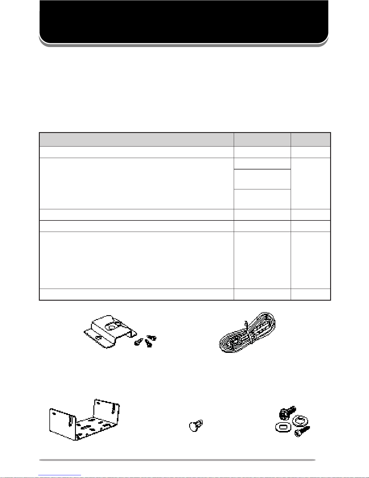
SUPPLIED ACCESSORIES
DC power cable kitMicrophone hanger
with self-tapping screws
Mounting bracket Screw setSpeaker jack cap
metI rebmuNtraP ytitnauQ
swercsgnippat-fleshtiwregnahenohporciMXX-4851-91Jtes1
tikelbacrewopCDXX-9333-03E
tes1
esufA01•
)G268-KT/G068-KT/G267-KT/G067-KT(
XX-6100-15F
esufA51•
)GH268-KT/GH068-KT/GH267-KT/GH067-KT(
XX-7100-15F
tekcarbgnitnuoMXX-7260-92J1
packcajrekaepSXX-5320-90B1
:teswercS
XX-5930-99N1
)seceip4(wercsgnippat-fleS•
)seceip4(rehsawhtiwwercsdedaeh-xeH•
)seceip4(rehsawgnirpS•
)seceip4(rehsawtalF•
launamnoitcurtsnIXX-7521-26B1
UNPACKING AND CHECKING EQUIPMENT
2
VARIOUS ELECTRONIC EQUIPMENT IN YOUR VEHICLE MAY MALFUNCTION IF THEY
ARE NOT PROPERLY PROTECTED FROM THE RADIO FREQUENCY ENERGY WHICH IS
PRESENT WHILE TRANSMITTING. ELECTRONIC FUEL INJECTION, ANTI-SKID BRAKING,
AND CRUISE CONTROL SYSTEMS ARE TYPICAL EXAMPLES OF EQUIPMENT THAT MA Y
MALFUNCTION. IF YOUR VEHICLE CONT AINS SUCH EQUIPMENT, CONSULT THE
DEALER FOR THE MAKE OF VEHICLE AND ENLIST HIS AID IN DETERMINING IF THEY
WILL PERFORM NORMALLY WHILE TRANSMITTING.
Note: The following preparation instructions are for use by your KENWOOD dealer, an authorized
KENWOOD service facility, or the factory.
TOOLS REQUIRED
Note: Before installing the transceiver, always check how far the mounting screws will extend below the
mounting surface. When drilling mounting holes, be careful not to damage vehicle wiring or parts.
The following tools are required for installing the transceiver:
• 6 mm (1/4 inch) or larger electric drill
• Drill bits (sizes listed below) and circle cutters
POWER CABLE CONNECTION
THE TRANSCEIVER OPERATES IN 12 V NEGATIVE GROUND SYSTEMS ONLY! CHECK
THE BATTERY POLARITY AND VOLTAGE OF THE VEHICLE BEFORE INSTALLING THE
TRANSCEIVER.
1 Check for an existing hole, conveniently located in the firewall, where the
power cable can be passed through.
• If no hole exists, use a circle cutter to drill the firewall, then install a rubber grommet.
2 Run the two power cable leads through the firewall and into the engine
compartment, from the passenger compartment.
3 Connect the red lead to the positive (+) battery terminal and the black lead to
the negative (–) battery terminal.
• Locate the fuse as close to the battery as possible.
4 Coil and secure the surplus cable.
• Be sure to leave enough slack in the cables so the transceiver can be removed for
servicing while keeping the power applied.
PREPARATION
eziStiBllirD esopruP
)hcni23/5(mm2.4swercsgnippat-flesmm61x5
)hcni8/1(mm2.3swercsgnippat-flesmm61x4
3
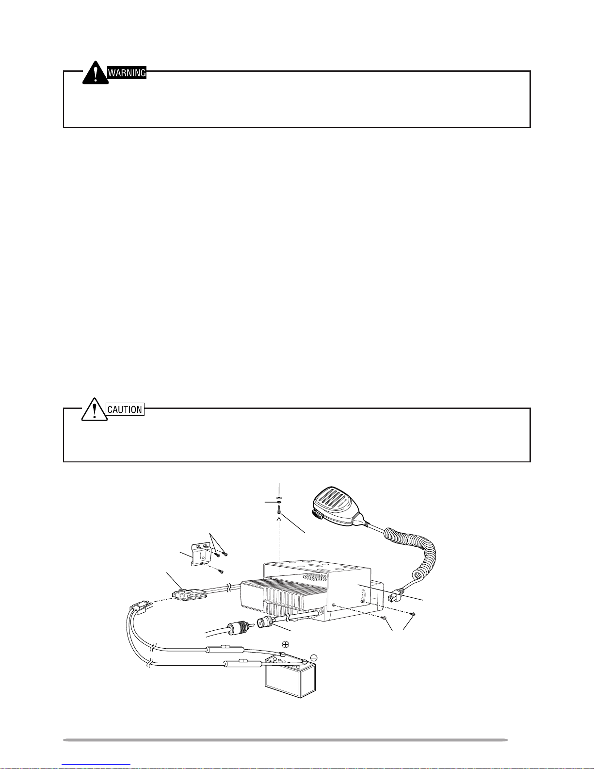
INSTALLING THE TRANSCEIVER
FOR P ASSENGER SAFETY, INSTALL THE TRANSCEIVER SECURELY, USING THE
SUPPLIED MOUNTING BRACKET, SO THE TRANSCEIVER WILL NOT BREAK LOOSE IN
THE EVENT OF A COLLISION.
1 Mark the position of the holes in the dash, using the mounting bracket as a
template. Drill the holes, then attach the mounting bracket using the 4
supplied 5 x 16 mm screws, the spring washers, and the flat washers.
• Be sure to mount the transceiver in a location where the controls are within easy reach
of the user, and where there is sufficient space at the rear of the transceiver for cable
connections.
2 Connect the antenna and the supplied power cable to the transceiver.
3 Slide the transceiver into the mounting bracket and secure it using the 4
supplied hex-headed screws.
4 Mount the microphone hanger, using the 3 supplied 4 x 16 mm screws, in a
location where it will be within easy reach of the user.
• The microphone and microphone cable should be mounted in a place where they will
not interfere with the safe operation of the vehicle.
5 Connect the optional microphone to the microphone jack on the front panel of
the transceiver. Place the microphone on the hanger.
WHEN REPLACING THE FUSE IN THE DC POWER CABLE, BE SURE TO REPLACE IT
WITH A FUSE OF THE SAME VALUE.
NEVER
REPLACE A FUSE WITH A FUSE THAT HAS
A HIGHER VALUE.
Hex-headed screw
Microphone hanger
DC power cable
Mounting bracket
5 x 16 mm
self-tapping screw
4 x 16 mm self-tapping screw
Spring washer
Flat washer
Antenna
connector
Power input connector
12 V vehicle
battery
* The above diagram shows the M market transceiver. The antenna connector of the E market
transceiver is different. A market code (M or E) can be found on the label attached to the package box.
Optional KMC-30
speaker/ microphone
4
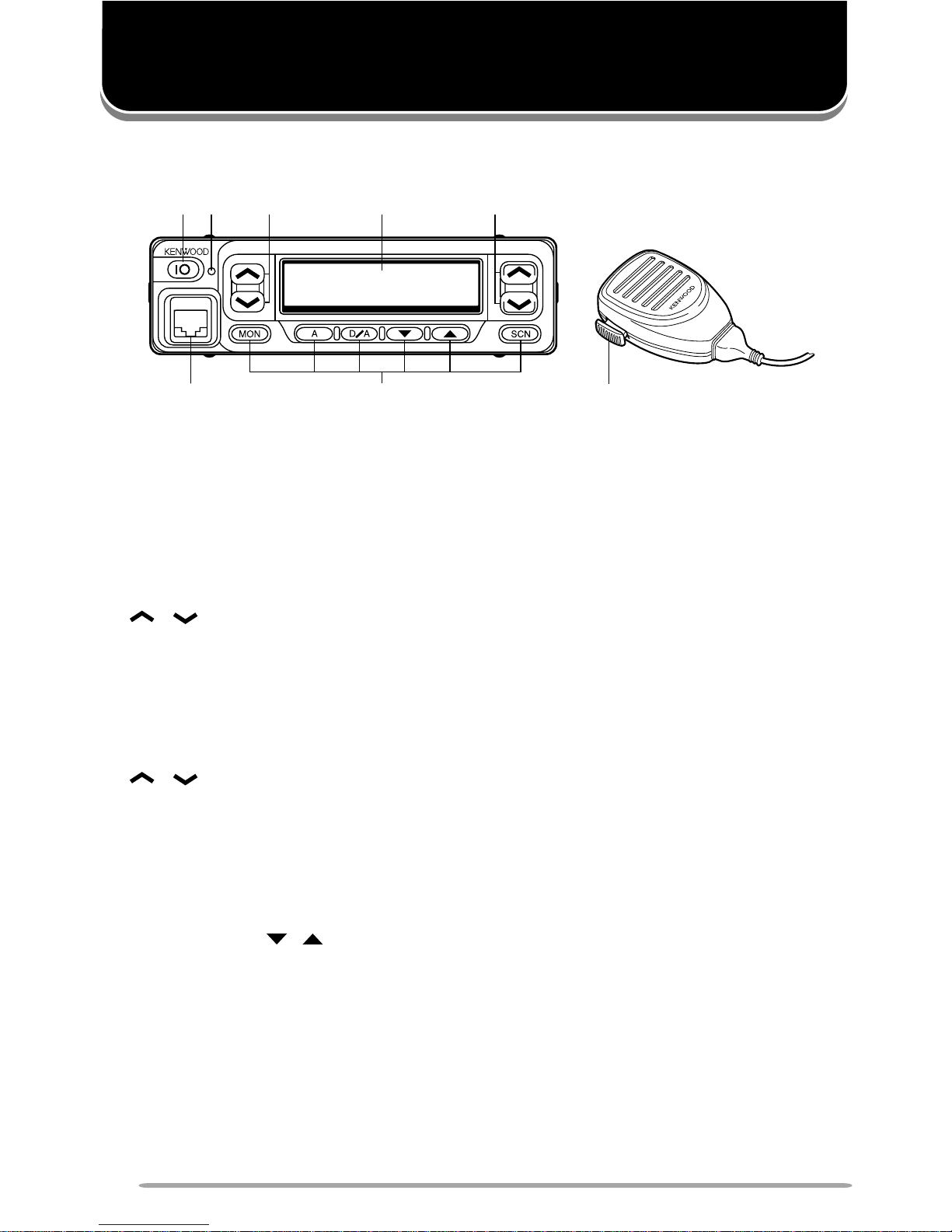
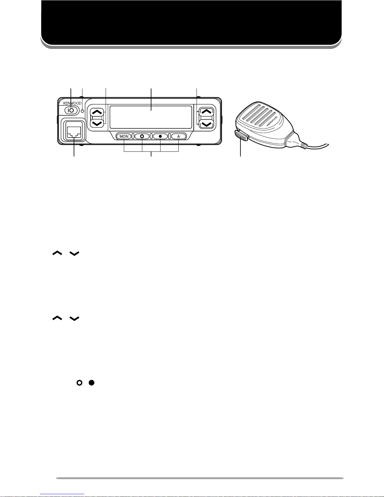
GETTING ACQUAINTED (TK-760G series/ TK-860G series)
FRONT PANEL AND MICROPHONE
q
yu
w rt
e
i
qq
qq
q
IO (Power) switch
Press to switch the transceiver ON (or OFF).
ww
ww
w LED indicator
Lights red while transmitting. Lights green while receiving. If programmed by
the dealer, flashes orange while receiving a Code Squelch or Selective Call
code, or a 2-Tone code that matches the one set up in your transceiver.
ee
ee
e
/ keys
These are PF (Programmable Function) keys. Press each key to activate its
auxiliary function {page 8}. The default settings are Volume Up and Volume
Down.
rr
rr
r Display
See page 5.
tt
tt
t / keys
These are PF (Programmable Function) keys. Press each key to activate its
auxiliary function {page 8}. The default settings are Channel Up and
Channel Down.
yy
yy
y Microphone jack
Insert the microphone plug into this connector.
uu
uu
u MON, A, D/A, , , and SCN keys
These are PF (Programmable Function) keys. Press each key to activate its
auxiliary function {page 8}.
ii
ii
i PTT (Push-to-Talk) switch
Press this switch, then speak into the microphone to call a station.
* Optional KMC-30
speaker/ microphone
5
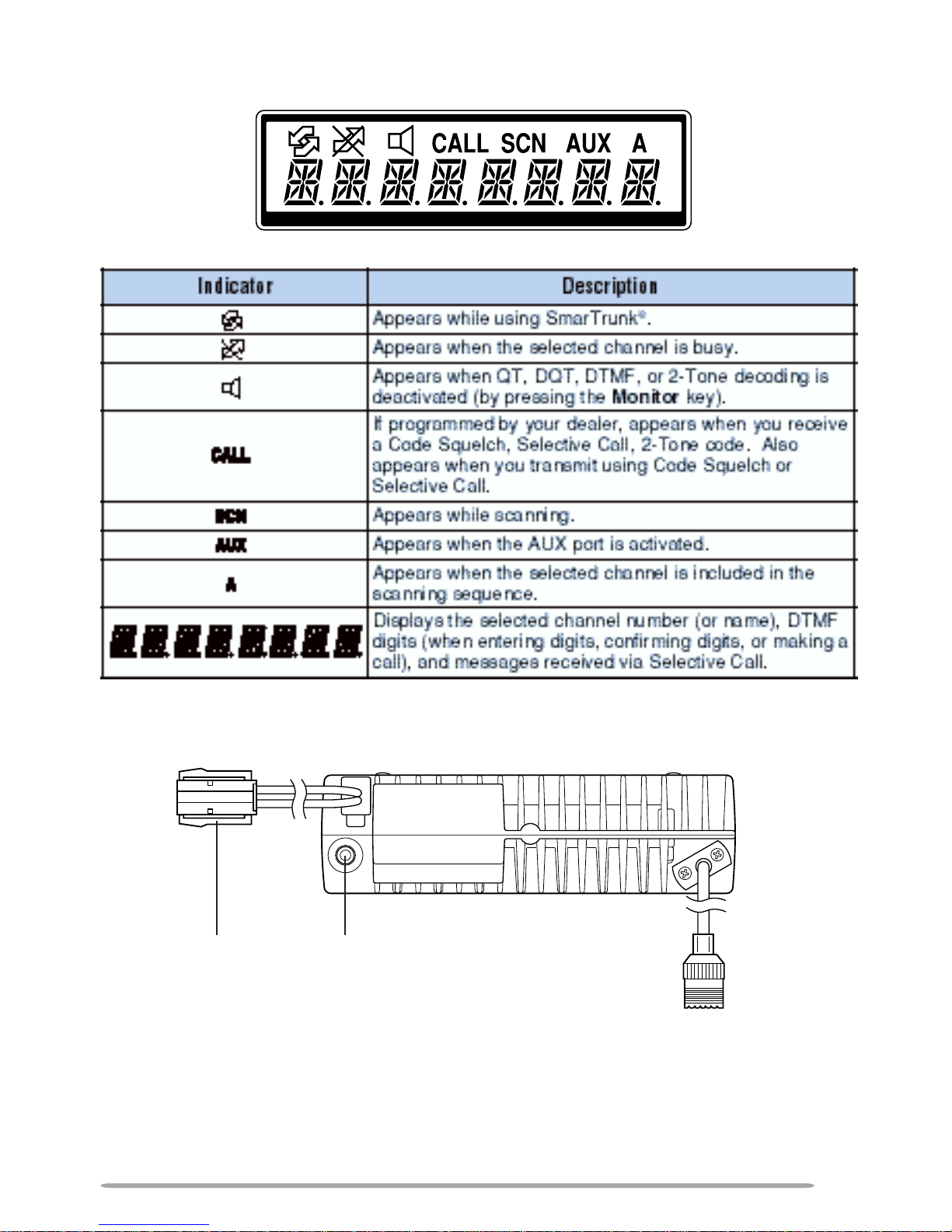
DISPLAY
REAR PANEL
External
speaker jack
Power input
connector
Antenna connector
* The above diagram shows the M market transceiver. The antenna connector of the E market
transceiver is different. A market code (M or E) can be found on the label attached to the package box.
6
FRONT PANEL AND MICROPHONE
qq
qq
q IO (Power) switch
Press to switch the transceiver ON (or OFF).
ww
ww
w LED indicator
Lights red while transmitting. Lights green while receiving. If programmed by
your dealer, flashes orange while receiving a Code Squelch or Selective Call
code, or a 2-Tone code that matches the one set up in your transceiver.
ee
ee
e / keys
These are PF (Programmable Function) keys. Press each key to activate its
auxiliary function {page 8}. The default settings are Volume Up and Volume
Down.
rr
rr
r Display
See page 7.
tt
tt
t / keys
These are PF (Programmable Function) keys. Press each key to activate its
auxiliary function {page 8}. The default settings are Channel Up and
Channel Down.
yy
yy
y Microphone jack
Insert the microphone plug into this connector.
uu
uu
u MON, , , and A keys
These are PF (Programmable Function) keys. Press each key to activate its
auxiliary function {page 8}.
ii
ii
i PTT (Push-to-Talk) switch
Press this switch, then speak into the microphone to call a station.
GETTING ACQUAINTED (TK-762G series/ TK-862G series)
q
yu
w rt
e
i
* Optional KMC-30
speaker/ microphone
7
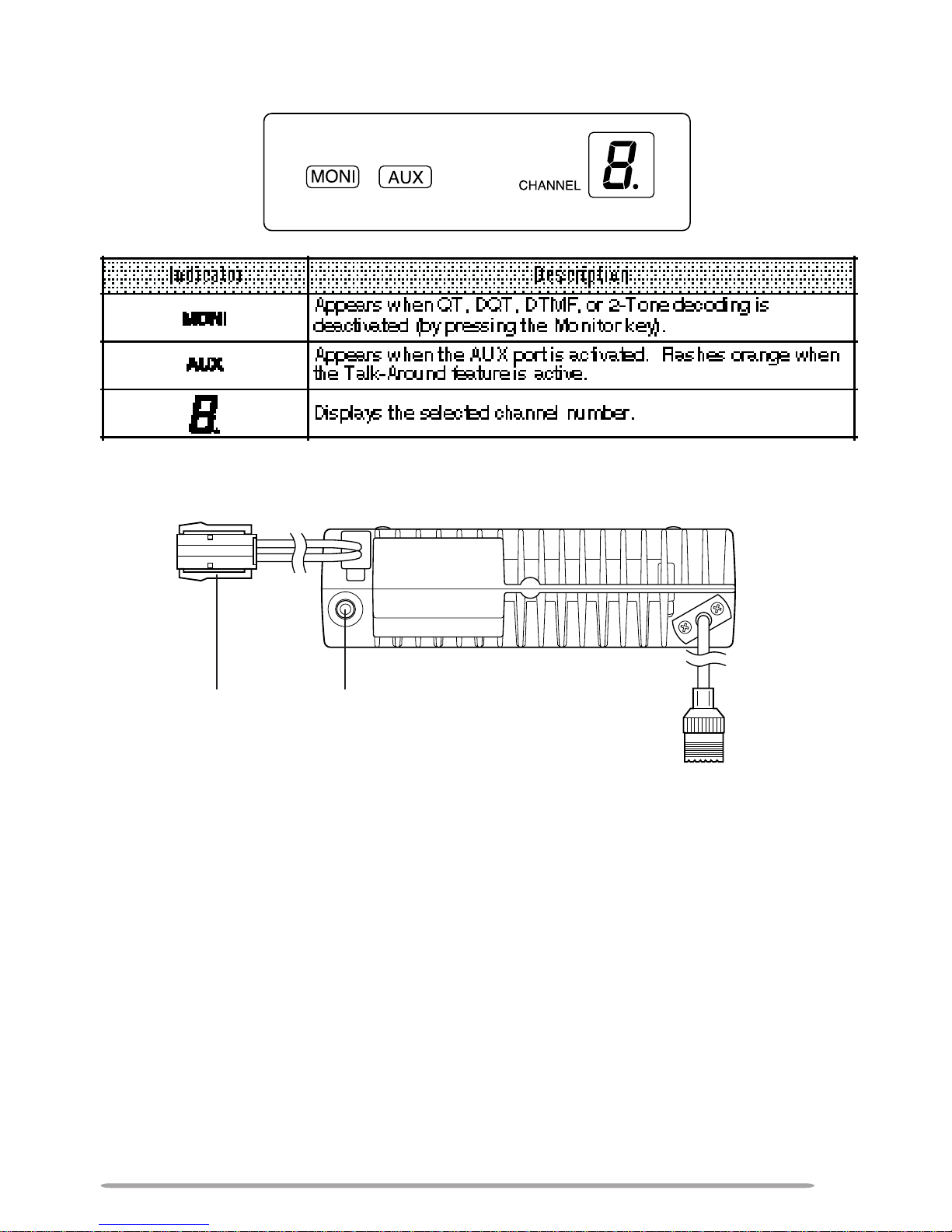
DISPLAY
REAR PANEL
External
speaker jack
Power input
connector
Antenna connector
* The above diagram shows the M market transceiver. The antenna connector of the E market
transceiver is different. A market code (M or E) can be found on the label attached to the package box.

8
The following keys can be programmed with the functions listed below.
TK-760G series/ TK-860G series: / (left side) , / (right side), MON,
A, D/A, , , and SCN.
TK-762G series/ TK-862G series: / (left side) , / (right side), MON,
, , and A.
• AUX
• Channel Down
• Channel Up
• Display Character (TK-760G/ TK-860G only)
• Group Down (TK-760G/ TK-860G only)
• Group Up (TK-760G/ TK-860G only)
• Home Channel
• Horn Alert
• Key Lock
• Monitor A (Monitor Unmute–Momentary)
• Monitor B (Monitor Unmute–Toggle)
• Monitor C (Carrier Squelch–Momentary)
• Monitor D (Carrier Squelch–Toggle)
• None (No function)
• Public Address
• Redial
• Scan (TK-760G/ TK-860G only)
• Scan Del/Add (TK-760G/ TK-860G only)
• Selectable QT (TK-760G/ TK-860G only; M market only)
• Talk-Around
• Volume Up
• Volume Down
• 2-Tone Encode *
*
The code for the TK-762G/ TK-862G transceiver is not selectable. You can transmit only one 2-Tone
code, which is pre-programmed in the transceiver.
The Emergency function can also be programmed (M market only). However, it
can only be used with a foot switch.
PROGRAMMABLE AUXILIAR Y FUNCTIONS

9
OPERATING BASICS
SWITCHING POWER ON/OFF
Press the IO switch to switch the transceiver ON (or OFF).
TK-760G/ TK-860G only: If the Radio Password function is programmed,
“PASSWORD” will appear on the display when the power is turned ON. To
unlock the transceiver, enter the password, then press the SCN key. If you enter
the wrong password, an error tone sounds and the transceiver remains locked.
The password can contain a maximum of 6 digits.
ADJUSTING THE VOLUME
Press the keys programmed as Volume Up and Volume Down to adjust the
volume. Volume Up increases the volume and Volume Down decreases it.
• You may need to adjust the volume more precisely while communicating with another
party.
Note: If your dealer programmed Monitor A or Monitor B onto a PF key, you can press that key to hear
background noise while adjusting the volume level (refer to “MONITOR” on page 19).
SELECTING A GROUP OR CHANNEL
Select the desired group or channel using the keys programmed as Group Up/
Down or Channel Up/Down.
• If a group or channel has not been programmed, it cannot be used.
Note:
◆
Group Up/Down cannot be used on the TK-762G/ TK-862G transceivers.
◆
TK-760G/ TK-860G features 128-channel capacity. In order to manage 128 channels easily, one or
more programmed channels can be bundled together as a group.
◆
Your dealer may have programmed both Group Up/Down and Channel Up/Down keys. In this
case, select the desired group and channel number. Please consult your dealer for details.

10
PLACING A CALL
1 Make sure no parties are currently transmitting on your selected channel.
2 Press the PTT switch, then speak into the microphone in your normal
speaking voice.
• For best sound quality at the receiving station, hold the microphone approximately
1.5 inches (3 ~ 4 cm) from your mouth.
3 Release the PTT switch to receive.
RECEIVING A CALL
Your dealer may have programmed QT or DQT signalling on your transceiver. If
your selected channel is programmed with one of these features, you will hear
calls only when another party in your system makes a call. All other calls will not
be heard.
If your selected channel is not set up with QT or DQT, you will hear calls made
by any party (not just those in your system).

11
Scan is useful for monitoring signals on the transceiver channels. When
scanning, the transceiver checks for a signal on each channel, and only stops on
a channel if a signal is present.
The transceiver will remain on a busy channel until the signal is no longer
present. Your dealer programs the delay time between signal drop-out and scan
resumption. If a signal is received during the delay time, the transceiver will
remain on the same channel.
Note:
◆
You can only use Scan if your dealer has programmed at least 2 channels on the transceiver . Also,
there must be at least 2 channels not locked out of Scan.
◆
Ask your dealer for an explanation on how Channel Scan functions when using Code Squelch,
Selective Call, or 2-T one signalling.
To start scanning, press the key programmed as Scan.
• Scanning starts from the current channel and ascends through the channel numbers.
• The SCN icon and “SCAN” appear on the display.
To end Scan, press the Scan key again.
PRIORITY SCAN
If your dealer set up a priority channel on your transceiver, the transceiver will
continuously monitor that channel while receiving a signal on another channel.
When a signal is received on the Priority channel, the transceiver immediately
switches to that channel. (“P” appears on the display.)
The transceiver remains on the Priority channel until the signal drops out. Your
dealer programs the delay time between signal drop-out and scan resumption.
CHANNEL LOCKOUT
If programmed by your dealer, you can select channels to lock out of the
scanning sequence. Perform the following steps while not in Scan mode.
1 Use the keys programmed as Channel Up and Channel Down to select the
channel you want to lock out of Scan.
2 Press the key programmed as Scan Del/Add.
• Each press of Scan Del/Add toggles the lockout status of the selected channel.
• Channels that are included in Scan are represented by an “A” on the display.
Channels locked out of Scan do not have an “A” on the display.
REVERT CHANNEL
During Scan, pressing the PTT switch to transmit will cause the transceiver to
select the revert channel. Your dealer programs the Revert channel for your
transceiver. Consult your dealer for details.
CHANNEL SCAN (TK-760G/ TK-860G only)

12
DTMF CALLS
Note: To make DTMF calls, you must have an optional microphone with a DTMF keypad. Ask your
dealer for more information.
MANUAL DIALLING
Method 1:
Press and hold the PTT switch, then enter the digits on the microphone keypad.
• You can enter the digits 0 ~ 9, A ~ D, , and #. (A ~ D may be disabled by your dealer.)
• If programmed by your dealer, you do not need to continuously hold the PTT switch. The
transceiver will remain in the transmit state for 2 seconds after releasing each key.
• While transmitting DTMF tones, the microphone is muted. You can monitor tones as they
are transmitted by listening to the speaker audio.
Method 2:
1 Enter the digits on the microphone keypad (16 digits maximum).
• TK-760G/ TK-860G only: Each digit appears on the display as it is entered and its
corresponding DTMF tone sounds.
• You can enter the digits 0 ~ 9, A ~ D,
, and #. (A ~ D may be disabled by your
dealer, however you can still enter them if desired.)
• If you enter a wrong digit or decide not to dial the number, press any key on the
transceiver front panel other than the IO switch, to exit.
2 Press the PTT switch to make the call.
• TK-760G/ TK-860G only: The digits scroll across the display and their corresponding
DTMF tone sounds.
• If programmed by your dealer, no DTMF tone will sound when “D” is transmitted. “D” is
used for a pause time. The pause duration is programmed by your dealer.
STORING DTMF NUMBERS
Note: Auto Dialling must first be activated by your dealer .
You can store DTMF numbers (16 digits maximum) in each of the 9 Auto Dial
memory locations (1 ~ 9).
1 Press the microphone # key.
• “D” appears on the display.
2 Enter the desired digits on the microphone keypad.
• You can enter the digits 0 ~ 9, A ~ D, , and #. (A ~ D may be disabled by your
dealer, however you can still enter them if desired.) When entering “#”, you must first
press the PTT switch.
• To cancel, press any key on the transceiver front panel, other than IO switch.
3 Press the microphone # key, then enter a single digit number (1 ~ 9) for the
memory location.
• The original display is restored.

13
CONFIRMING STORED DTMF NUMBERS
To confirm the numbers stored in memory locations:
1 Press the microphone key.
• “A” appears on the display.
2 Enter the desired memory location number (1 ~ 9).
• TK-760G/ TK-860G only: The stored digits are displayed.
• If programmed by your dealer, no DTMF tone will sound when “D” is transmitted. “D” is
used for a pause time. The pause duration is programmed by your dealer.
3 Press any key other than the PTT switch to exit.
DIALLING STORED DTMF NUMBERS
To call a number stored in a memory location:
1 Press the microphone key.
• “A” appears on the display.
2 Enter the desired memory location number (1 ~ 9).
• TK-760G/ TK-860G only: The stored digits are displayed.
3 Press the PTT switch.
• If programmed by your dealer, no DTMF tone will sound when “D” is transmitted. “D” is
used for a pause time. The pause duration is programmed by your dealer.
CLEARING STORED DTMF NUMBERS
To clear the numbers from a memory location:
1 Press the microphone # key twice.
• “D- CLR” appears on the display.
• To cancel the process, press any key other than 1 ~ 9.
2 Enter the desired memory location number (1 ~ 9).
REDIALLING
You can redial the last number you transmitted (16 digits maximum).
1 Press the microphone key, then press the 0 key. Or, if Redial has been
programmed onto a key, simply press the Redial key.
• “A” appears.
• TK-760G/ TK-860G only: The digits are displayed as well.
2 Press the PTT switch.
Note: Switching OFF the transceiver power clears the redial memory.

14
Code Squelch is enabled or disabled by your dealer. This function turns the
transceiver squelch OFF only when it receives the DTMF code that has been set
up in your transceiver. Transceivers that do not transmit the correct code will not
be heard. Consequently, you can communicate with a specific party without
listening to other parties using the same channel.
Your dealer may also activate Group Call for your transceiver. This is useful
when you want to send information to a number of units in a fleet. Ask your
dealer for details.
Note: Code Squelch cannot be used on channels programmed with Selective Call or 2-Tone Signalling.
RECEIVING
When you receive a signal containing the correct code, squelch turns OFF and
you will hear the call.
• “CALL” appears on the display and the LED indicator flashes orange.
• To mute the speaker after squelch turns OFF, press the key programmed as Monitor.
• Your dealer can program squelch to automatically turn back ON after a specific time period
elapses.
• If T ranspond for Code Squelch is programmed, an acknowledgment signal is returned to
the calling station. Transpond does not function when you are called with a Group code.
Transpond for Code Squelch can send an alert tone, a transceiver ID code, or a code
stored in memory location 1.
• If Call Alert for Code Squelch is programmed, an alert tone will sound when the correct
code is received.
TRANSMITTING
1 Press and hold the PTT switch.
2 Enter the code of the transceiver you want to call or enter a Group code on
the keypad.
• If desired, you can send codes the same way you make DTMF calls {page 12}. Both
manual methods can be used or you can store codes in memory, then dial them from a
memory location.
• “CALL” appears on the display and the LED indicator lights red.
3 Use the transceiver the same as in a regular call; press the PTT switch to
transmit and release it to receive.
• The called transceiver’ s squelch will turn OFF while you are transmitting. After you
stop transmitting, the squelch will turn back ON after a pre-set time period elapses.
This time period is programmed by your dealer.
• When you release the PTT switch, squelch turns OFF and the LED indicator flashes
orange (depending on dealer programming). When you receive a signal, the LED
indicator alternates between green and orange. When the signal drops out, the LED
indicator flashes orange again. If no signal is received for a pre-determined time,
squelch turns back ON.
• Pressing the key programmed as Monitor at any time will turn the squelch back ON.
CODE SQUELCH

15
Selective Call is enabled or disabled by your dealer. This function is similar to
Code Squelch {page 14}. The differences from Code Squelch are:
• You can send or receive message codes containing a maximum of 5 digits.
• Selective Call turns the squelch OFF only when the transceiver receives a predetermined
DTMF code in the correct sequence:
1) A 3-digit ID code
2) A 1-digit Intermediate code
3) A message code (up to 5 digits)
Your dealer may also activate Group Call for your transceiver. This is useful
when you want to pass information to a number of units in a fleet. Ask your
dealer for details.
Note: Selective Call cannot be used on channels programmed with Code Squelch or 2-Tone Signalling.
RECEIVING
When you receive the correct ID and Intermediate codes, squelch turns OFF and
you will hear the call. If a message code is also received, the message appears
on the display
• “CALL” appears on the display and the LED indicator flashes orange.
• When you receive a call with your ID code, “C” appears on the display (i.e.- C 12345).
• When you receive a call with your Group code, “A” appears on the display (i.e.- A 12345).
• When no message is received, “NO DATA” appears on the display.
• You can clear a message by pressing any key other than the IO switch.
• To mute the speaker after squelch turns OFF, press the key programmed as Monitor.
• Your dealer can program squelch to automatically turn back ON after a specific time period
elapses.
• If T ranspond for Selective Call is programmed, an acknowledgment signal is returned to
the calling station. Transpond does not function when you are called with a Group code.
Transpond for Selective Call can send an alert tone, a transceiver ID code, or a code
stored in memory location 1.
• If Call Alert for Selective Call is programmed, an alert tone will sound when the correct
code is received.
SELECTIVE CALL (TK-760G/ TK-860G only)

16
TRANSMITTING
Note: You can also transmit using a TK-762G/ TK-862G transceiver.
1 Press and hold the PTT switch.
2 Enter the code of the transceiver you want to call or enter a Group code on
the keypad.
• Be sure to enter the ID or Group code, followed by the Intermediate code of the
transceiver you want to call. If desired, you can also enter a message code of up to 5
digits.
• If desired, you can send codes the same way you make DTMF calls {page 12}. Both
manual methods can be used or you can store codes in memory, then dial them from a
memory location.
• TK-760G/ TK-860G only: “CALL” appears on the display and the LED indicator lights
red.
3 Use the transceiver the same as in a regular call; press the PTT switch to
transmit and release it to receive.
• When you release the PTT switch, squelch turns OFF and the LED indicator flashes
orange (depending on dealer programming). When you receive a signal, the LED
indicator alternates between green and orange. When the signal drops out, the LED
indicator flashes orange again. If no signal is received for a pre-determined time,
squelch turns back ON.
• Pressing the key programmed as Monitor at any time will turn the squelch back ON.

17
2-Tone Signalling is enabled or disabled by your dealer. This function turns the
transceiver squelch OFF only when it receives the 2-tone signal that has been
set up in your transceiver. Transceivers that do not transmit the correct tones will
not be heard.
Your dealer may also activate Group Call for your transceiver. Ask your dealer
for details.
RECEIVING
When you receive a signal containing the correct tones, squelch turns OFF and
you will hear the call.
• “CALL” appears on the display and the LED indicator flashes orange.
• To mute the speaker after squelch turns OFF, press the key programmed as Monitor.
• Your dealer can program squelch to automatically turn back ON after a specific time period
elapses.
• If T ranspond for 2-Tone Signalling is programmed, an acknowledgment signal is returned
to the calling station. T ranspond for 2-Tone Signalling can transmit an alert tone only.
• If Call Alert for 2-Tone code is programmed, an alert tone will sound when the correct tones
are received.
TRANSMITTING
1 Press the key programmed as 2-Tone Encode.
• A pre-programmed 2-tone code name appears on the display.
2 Press the keys programmed as Channel Up and Channel Down to select
your desired 2-Tone code name. (TK-760G series/ TK-860G series only)
3 Press the PTT switch and 2-Tone Encode key to transmit and release them
to receive.
• When you release the PTT switch and the 2-Tone Encode key, squelch turns OFF and
the LED indicator flashes orange (depending on dealer programming). When you
receive a signal, the LED indicator alternates between green and orange. When the
signal drops out, the LED indicator flashes orange again. If no signal is received for a
pre-determined time, squelch turns back ON.
• Pressing the key programmed as Monitor at any time will turn the squelch back ON.
Note: The code for the TK-762G series/ TK-862G series transceiver is not selectable. You cannot
change the tone in step 2 by using the Channel Up and Channel Down keys.
2-TONE SIGNALLING

18
TIME-OUT TIMER (TOT)
The purpose of the Time-out Timer is to prevent any caller from using a channel
for an extended period of time.
If you continuously transmit for a period of time that exceeds the programmed
time, the transceiver will stop transmitting and an alert tone will sound. To stop
the tone, release the PTT switch.
Your dealer can program a warning function to alert you before the TOT expires.
Continuously transmitting for the time specified by your dealer will cause the
warning tone to sound.
BUSY CHANNEL LOCKOUT (BCL)
The Busy Channel Lockout feature is activated or deactivated by your dealer.
When activated, BCL prevents you from interfering with other parties who may
be using the same channel that you selected. Pressing the PTT switch while the
channel is in use will cause your transceiver to emit an alert tone and
transmission will be inhibited (you cannot transmit). Release the PTT switch to
stop the tone and return to receive mode.
TALK-AROUND
You may occasionally experience an interruption in service (due to a power
failure, etc.). During such an occurence, you can continue communication by
using the Talk-Around feature, if it has been programmed by your dealer. TalkAround allows you to communicate directly with other transceivers, without the
use of a repeater. However, if the station you want to contact is too far away, or
there are geographical obstacles in the way, you may not be able to contact the
station.
Toggle Talk-Around ON and OFF by pressing the key programmed as Talk-
Around.
• TK-760G/ TK-860G only: “T” or “TA” appears on the display while Talk-Around is active.
• TK-760G/ TK-860G only: AUX flashes orange.
• When using Talk-Around, the “receive” frequency is used for both transmission and
reception, and the QT/DQT “decode” signalling is used for both encoding and decoding.
HORN ALERT
When a call is received that has correct DTMF codes or 2-tone signalling, Horn
Alert causes the vehicle horn or some other external alert to sound. This
function notifies you of a received call when you are out of your vehicle.
Toggle Horn Alert ON and OFF by pressing the key programmed as Horn Alert.
ADVANCED OPERATIONS

19
MONITOR
Your dealer can program a key with the Monitor function one of four ways:
A Press and hold the Monitor key to hear background noise. Release the key to return to
normal operation.
B Momentarily press the Monitor key to hear background noise. Press the key again to
return to normal operation.
C Press and hold the Monitor key to deactivate QT, DQT, DTMF, or 2-Tone signalling.
Release the key to return to normal operation.
D Momentarily press the Monitor key to deactivate QT, DQT , DTMF, or 2-Tone signalling.
Press the key again to return to normal operation.
You can use the Monitor key to listen to weak signals that you cannot hear
during normal operation and to adjust the volume when no signals are present
on your selected channel.
BEGINNING/ END OF TRANSMISSION ID SIGNAL
Your dealer can enable or disable the Beginning/ End of Transmission
identification signals. These signals are used to access and release some
repeaters and telephone systems. Ask your dealer which method has been set
up on your transceiver.
To send a Beginning of Transmission ID SIGNAL, either press the PTT switch, or
press the key two times.
To send an End of Transmission ID SIGNAL, either release the PTT switch or
press the key followed by the # key.
PUBLIC ADDRESS (PA)
To use the Public Address system, your dealer must install the optional PA unit
(KAP-1) and an external speaker. This function causes all audio input via the
microphone to be amplified and output from the external speaker.
To use the PA system:
1 Press the key programmed as Public Address.
2 Press the PTT switch, then speak into the microphone.
• Use the Volume Up and Volume Down keys to adjust the audio output from the
external speaker .
3 To return to normal operation, press the Public Address key again.
AUX
A control port has been provided on this transceiver for an external board. Press
the key programmed as AUX to activate or deactivate the AUX port.
 Loading...