


VHF FM TRANSCEIVER
TK-7150
SERVICE MANUAL
Microphone
(T91-0621-15)
© 2002-10 PRINTED IN JAPAN
B51-8633-00 (N) 843
Cabinet
(A01-2185-12)
Knob
(K29-9221-03) x 2
Key top
(K29-9222-02)
CONTENTS
GENERAL .................................................. 2
SYSTEM SET-UP ...................................... 3
OPERATING FEATURES .......................... 4
REALIGNMENT ......................................... 5
INSTALLATION ......................................... 7
CIRCUIT DESCRIPTION .......................... 12
SEMICONDUCTOR DATA ...................... 16
COMPONENTS DESCRIPTION .............. 20
PARTS LIST ............................................. 22
EXPLODED VIEW.................................... 32
PACKING ................................................. 33
Panel assy
(A62-1037-03)
ADJUSTMENT ........................................ 34
PC BOARD
DISPLAY UNIT (X54-3400-10) ............ 45
TX-RX UNIT (X57-6570-10) ................ 49
SCHEMATIC DIAGRAM.......................... 55
BLOCK DIAGRAM ................................... 63
WIRING.................................................... 65
TERMINAL FUNCTION ........................... 66
OPTIONS ................................................. 68
SPECIFICATIONS .................................... 69

TK-7150
GENERAL
INTRODUCTION
SCOPE OF THIS MANUAL
This manual is intended for use by experienced technicians familiar with similar types of commercial grade communications equipment. It contains all required service information for the equipment and is current as of this publication
data. Changes which may occur after publication are covered
by either Service Bulletins or Manual Revisions. These are
issued as required.
ORDERING REPLACEMENT PARTS
When ordering replacement parts or equipment information, the full part identification number should be included.
This applies to all parts : components, kits, and chassis. If the
part number is not known, include the chassis or kit number
of which it is a part, and a sufficient description of the required component for proper identification.
PERSONNEL SAFETY
The following precautions are recommended for personnel safety :
•DONOT transmit if someone is within two feet (0.6
meter) of the antenna.
•DONOT transmit until all RF connectors are verified se-
cure and any open connectors are properly terminated.
• SHUT OFF and DO NOT operate this equipment near
electrical blasting caps or in an explosive atmosphere.
• All equipment should be properly grounded before power-
up for safe operation.
• This equipment should be serviced by a qualified techni-
cians only.
PRE-INSTALLATION CONSIDERNATIONS
1. UNPACKING
Unpack the radio from its shipping container and check for
accessory items. If any item is missing, please contact
KENWOOD immediately.
2. LICENSING REQUIREMENTS
Federal regulations require a station license for each radio
installation (mobile or base) be obtained by the equipment
owner. The licensee is responsible for ensuring transmitter
power, frequency, and deviation are within the limits permitted by the station license.
Transmitter adjustments may be performed only by a licensed technician holding an FCC first, second or general
class commercial radiotelephone operator’s license. There is
no license required to install or operate the radio.
3. PRE-INSTALLATION CHECKOUT
3-1. Introduction
Each radio is adjusted and tested before shipment. However, it is recommended that receiver and transmitter operation be checked for proper operation before installation.
3-2. Testing
The radio should be tested complete with all cabling and
accessories as they will be connected in the final installation.
Transmitter frequency, deviation, and power output should
be checked, as should receiver sensitivity, squelch operation,
and audio output. QT equipment operation should be verified.
4. PLANNING THE INSTALLATION
4-1. General
Inspect the vehicle and determine how and where the radio antenna and accessories will be mounted.
Plan cable runs for protection against pinching or crushing
wiring, and radio installation to prevent overheating.
4-2. Antenna
The favored location for an antenna is in the center of a
large, flat conductive area, usually at the roof center. The
trunk lid is preferred, bond the trunk lid and vehicle chassis
using ground straps to ensure the lid is at chassis ground.
4-3. Radio
The universal mount bracket allows the radio to be
mounted in a variety of ways. Be sure the mounting surface
is adequate to support the radio’s weight. Allow sufficient
space around the radio for air cooling. Position the radio
close enough to the vehicle operator to permit easy access to
the controls when driving.
4-4. DC Power and wiring
1. This radio may be installed in negative ground electrical
systems only. Reverse polarity will cause the cable fuse
to blow. Check the vehicle ground polarity before installa-
tion to prevent wasted time and effort.
2. Connect the positive power lead directly to the vehicle
battery positive terminal. Connecting the Positive lead to
any other positive voltage source in the vehicle is not rec-
ommended.
CAUTION
If DC power is to be controlled by the vehicle ignition switch,
a switching relay should be used to switch the positive power
lead. The vehicle ignition switch then controls DC to the relay
coil.
3. Connect the ground lead directly to the battery negative
terminal.
4. The cable provided with the radio is sufficient to handle
the maximum radio current demand. If the cable must be
extended, be sure the additional wire is sufficient for the
current to be carried and length of the added lead.
5. INSTALLATION PLANNING – CONTROL STATIONS
5-1. Antenna system
Control station. The antenna system selection depends
on many factors and is beyond the scope of this manual.
Your KENWOOD dealer can help you select an antenna system that will best serve your particular needs.
2

GENERAL / SYSTEM SET-UP
TK-7150
5-2. Radio location
Select a convenient location for your control station radio
which is as close as practical to the antenna cable entry point.
Secondly, use your system’s power supply (which supplies
the voltage and current required for your system). Make sure
sufficient air can flow around the radio and power supply to
allow adequate cooling.
SYSTEM SET-UP
Merchandise received
License and frequency
allocated by FCC
YES
YES
Frequency range
136~174MHz
Control cable KCT-22
M : 8 feet
M2 : 17 feet
M3 : 25 feet
Supplied key label
Choose the type of transceiver
Are you using
the remote kit?
NO
Are you using
the key label?
NO
SERVICE
This radio is designed for easy servicing. Refer to the
schematic diagrams, printed circuit board views, and alignment procedures contained in this manual.
RF power
50W
See page 8.
KRK-9
See page 7.
Type
TK-7150 K
Are you using
the voice scrambler/
ANI?
NO
Are you using
the ignition sense
cable?
NO
Transceiver programming
Are you using
the external speaker?
NO
DC power cable
Supplied cable or
KCT-23 M : 10 feet
KCT-23 M3 : 23 feet
Are you using
the keypad microphone?
NO
Are you using
the noise-canceling micro-
phone?
NO
Supplied microphone
YES
YES
YES
YES
YES
Modified of control unit
See page 5.
A personal computer (IBM PC or compatible), programming interface (KPG-46),
and programming software (KPG-79D) are required for programming.
External speaker KES-5
DC power supply KPS-10A
See page 9.
See page 7.
KCT-18
See page 7.
KMC-28A
KMC-27A
Desk top microphone KMC-9C
Delivery
3
TK-7150
OPERATING FEATURES
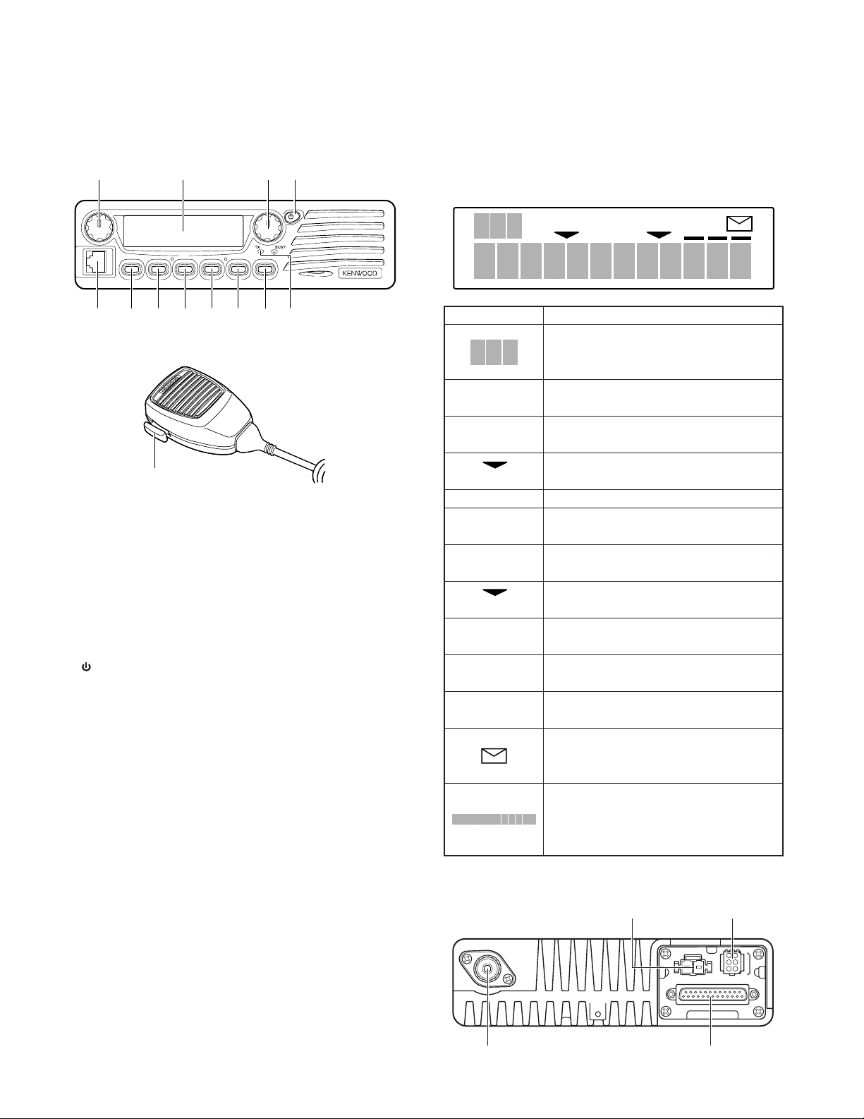
1. Controls and Functions
1-1. Front Panel
qwer
u
y
1-2. Microphone
!3
q Volume Control
Rotate to adjust the volume level. Clockwise increases
the volume and counterclockwise decreases the volume.
w Display
(See right.)
e Selector
Rotate to select a Zone or CH/GID (channel/group ID).
Clockwise increases the Zone / CH/GID and counterclockwise decreases the Zone / CH/GID. The default setting is
CH/GID Up/Down.
r (Power) switch
Press to switch the transceiver ON. Press and hold for
approximately 1 second to switch the transceiver OFF.
t Microphone Jack
Insert the microphone plug into this jack.
y PF1 Key
Press this key to activate its programmable auxiliary function. The default setting is Zone Up.
u PF2 Key
Press this key to activate its programmable auxiliary function. The default setting is Zone Down.
i PF3 Key
Press this key to activate its programmable auxiliary function. The default setting is None.
o PF4 Key
Press this key to activate its programmable auxiliary function. The default setting is None.
!0 PF5 Key
Press this key to activate its programmable auxiliary function. The default setting is None.
!1 PF6 Key
Press this key to activate its programmable auxiliary function. The default setting is None.
!2 TX / BUSY LEDs
The TX LED lights red while transmitting. In Conventional
Groups, the BUSY LED lights green while receiving.
4
!0t
oi!1 !2
!3 PTT switch
To transmit, press and hold this switch, then speak into
the microphone. Release to receive.
1-3. Display
CALL
Indicator Description
Displays the zone, group ID, and channel
numbers. Also displays various functions
which have been programmed by your dealer.
CALL
MON
(left side) the scan list.
SCN
SP
OP
(right side) ID is added to the scan list.
A
B
OS
Appears when the squelch opens during a
2-Tone or DTMF call.
Appears when the key programmed as
Monitor is pressed.
Appears when the selected Zone is added to
Appears when you are using Scan mode.
Appears when you are using an external
speaker.
Appears when the optional scrambler board
is installed and activated.
Appears when the selected Channel/Group
Appears when the auxiliary A function is
activated.
Appears when the auxiliary B function is
activated.
Appears when Operator Selectable Tone is
activated.
Appears when a FleetSync message is
stored in the transceiver memory. Appears
and blinks when a new message is received.
Displays the zone, group ID, and channel
numbers. Your dealer can program the zone,
group ID, and channel names with up to 12
characters, in place of numbers.
SCN SP OP OSABMON
1-4. Rear Panel
Power input
connector
Antenna
connector
6-pin connector
(for accessories)
25-pin connector
(for accessories)

REALIGNMENT
1. Modes 3. Panel Test Mode
User mode
[PF3]
Panel test mode
[PF1]+Power on
PC mode
Firmware programming mode
Clone mode
[PF6]+Power on
Firmware version
information
[PF3]+Power on
Mode Function
User mode For normal use.
Panel test mode Used by the dealer to check the funda-
Panel tuning mode Used by the dealer to tune the radio.
PC mode Used for communication between the
FPU data program- Used to read and write frequency data and
ming mode other features to and from the radio.
PC test mode Used to check the radio using the PC.
Firmware program- Used when changing the main program of
ming mode the flash memory.
Clone mode Used to transfer programming data from
Firmware version Used to confirm the internal firmware
information version.
Panel tuning mode
FPU data programming mode
PC test mode
[PF5]
Checksum
display mode
[PF4]
ment characteristics.
radio and PC (IBM compatible).
This feature is included in the FPU.
See panel tuning.
one radio to another.
PC tuning mode
2. How to Enter Each Mode
Mode Operation
User mode Power ON
Panel test mode [PF1]+Power ON
Panel tuning mode [Panel test mode]+[PF3]
PC mode Received commands from PC
Firmware programming mode
Checksum display mode
Clone mode [PF6]+Power ON
Firmware version information
[PF2]+Power ON
[Firmware programming mode]+[PF5]
[PF3]+Power ON (one second)
Setting method refer to “ADJUSTMENT”.
4. Panel Tuning Mode
Setting method refer to “ADJUSTMENT”.
5. PC Mode
5-1. Preface
The transceiver is programmed by using a personal computer, programming interface (KPG-46) and programming
software (KPG-79D).
The programming software can be used with an IBM PC
or compatible. Figure 1 shows the setup of an IBM PC for
programming.
5-2. Connection Procedure
1. Connect the transceiver to the personal computer with
the interface cable.
2. When the Power switch on, user mode can be entered
immediately. When PC sends command the radio enter
PC mode, and “PROGRAM” is displayed on the LCD.
When data transmitting from transceiver, the red LED is
blinking.
When data receiving to transceiver, the green LED is blink-
ing.
5-3. KPG-46 Description
(PC programming interface cable : Option)
The KPG-46 is required to interface the transceiver to the
computer. It has a circuit in its D-subconnector (25-pin) case
that converts the RS-232C logic level to the TTL level.
The KPG-46 connects the modular microphone jack of the
transceiver to the computers RS-232C serial port.
5-4. Programming Software Description
The KPG-79D programming disk is supplied in 3-1/2” disk
format. The software on this disk allows a user to program
the transceiver radio via programming interface cable (KPG-
46).
KPG-79D
TK-7150
IBM PC
KPG-46 or
KPG-46 +
Tuning cable
(E30-3383-05)
Fig. 1
TK-7150
5

TK-7150
REALIGNMENT
5-5. Programming With IBM PC
If data is transferred to the transceiver from an IBM PC
with the KPG-79D, the destination data (basic radio information) for each set can be modified. Normally, it is not necessary to modify the destination data because their values are
determined automatically when the frequency range (frequency type) is set.
The values should be modified only if necessary.
Data can be programmed into the flash memory in RS232C format via the modular microphone jack.
KPG-79D instruction manual parts No. : B62-1588-XX.
6. Firmware Programming Mode
6-1. Preface
The TK-7150 uses flash memory to allow it to be easily
upgraded when new features are released in the future.
6-2. Connection Procedure
Connect the TK-7150 to the personal computer (IBM PC or
compatible) with the interface cable (KPG-46). (Connection is
the same as in the PC mode.)
Note :
You can only program firmware from the 8-pin microphone connector on the front panel. Using the 25-pin logic
interface on the rear panel will not work.
6-3. Programming
1. Start up the programming software (Fpro. exe).
2. Set the communications speed (normally, 57600 bps) and
communications port in the configuration item.
3. Set the firmware to be updated by file name item.
4. Turn ON the transceiver while pressing and holding the
[PF2] key. The transceiver enters Firmware programming
mode and “PROG 57600”. If Firmware programming
mode is inhibited by the FPU, the transceiver enters User
mode instead.
If the transceiver receives the firmware data from a PC,
“PG” appears on the display.
5. Check the connection between the TK-7150 and the per-
sonal computer, and make sure that the TK-7150 is in the
program mode.
6. Press write button in the window. A window opens on
the display to indicate progress of writing.
7. If writing ends successfully, the TX LED on the TK-7150
lights.
8. If you want to continue programming other TK-7150, re-
peat steps 3 to 6.
Note :
This mode cannot entered if the firmware programming
mode is set to disable in the programming software (KPG79D).
6-4. Function
Each time you press the [PF4] key, the data transfer rate
alters (19200 / 38400 / 57600 bps).
Note :
Normally, write in the high-speed mode (57600 bps).
6
Firmware checksum display
PROG 57600
[PF4]
PROG 19200
[PF4]
PROG 38400
[PF4]
PROG 57600
[PF5]
SUM=[
****
[PF4]
]
Fig. 2
7. Clone Mode
Programming data can be transferred from one radio to
another by connecting them via their modular microphone
jacks. The operation is as follows (the transmit radio is the
master and the receive radio is a slave).
1. Turn the master TK-7150 power ON with the [PF6] key
held down. The TK-7150 displays “CLONE”.
If Firmware programming mode is inhibited by the FPU,
the transceiver enters User mode instead.
2. Power on the slave TK-7150.
3. Connect the cloning cable (No. E30-3382-05) to the modu-
lar microphone jacks on the master and slave.
4. Press the [PF6] key on the master while the master dis-
plays “CLONE”. The data of the master is sent to the
slave. While the slave is receiving the data, “PROGRAM”
is displayed. When cloning of data is completed, the mas-
ter displays “END”, and the slave automatically operates
in the User mode. The slave can then be operated by the
same program as the master.
5. The other slave can be continuously cloned. When the
[PF6] key on the master is pressed while the master dis-
plays “END”, the master displays “CLONE”. Carry out
the operation in steps 2 to 4.
6. To end cloning, first you must remove the cloning cable,
then switch both master and slave TK-7150s off.
Note :
Only the same models can be cloned together.
Cloning cable
(E30-3382-05)
Fig. 3
8. Firmware Version Information
This is a mode to confirm the internal firmware version.
1. Turn the transceiver ON while pressing the [PF3] key.
The firmware version will appear on the LCD.
When you release the [PF3] key, the transceiver automati-
cally enters User mode.
INSTALLATION
Cut
Tie wrap
Protective cover
4
5
Short plug
Black lead
Black/White lead
Speaker cable (to KES-5)
TK-7150
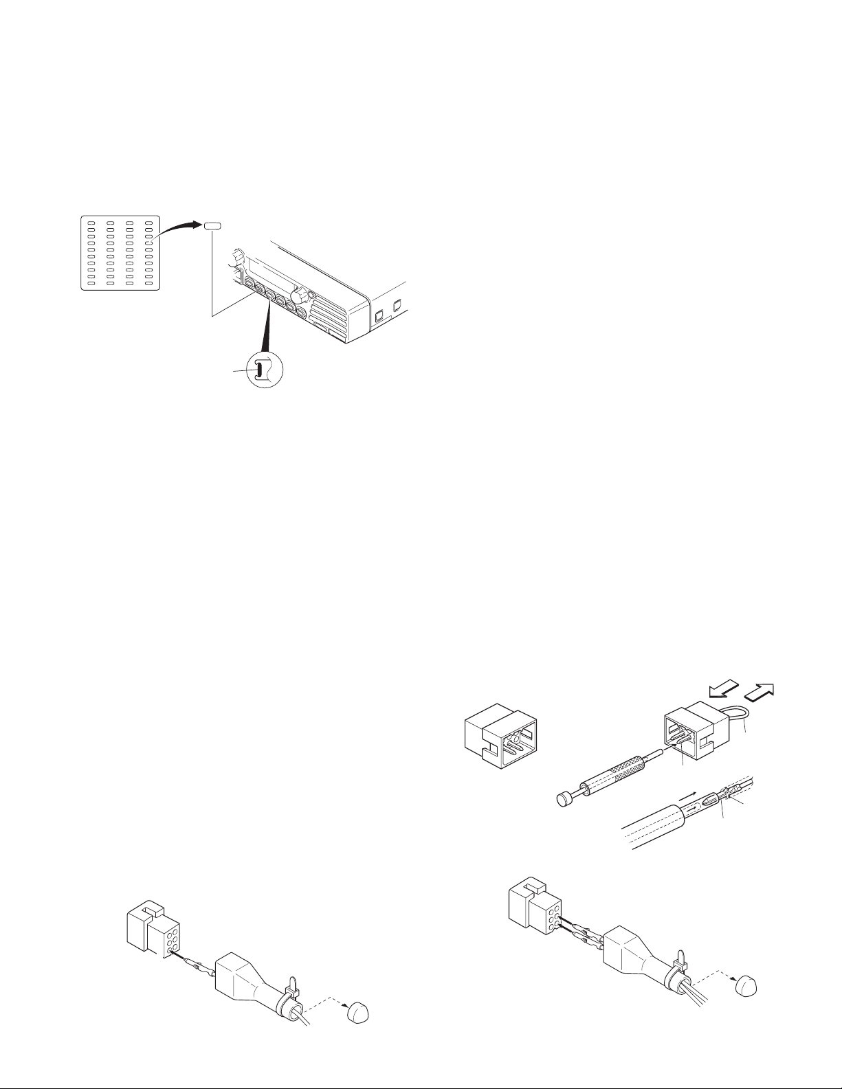
1. Installing Name Plate
Punch out the name plate card. Then insert the plates
onto the relative function keys.
You can reconfigure the name plates at any time.
Punch out the
name plate cards
Name plates for
the function keys
Squeeze and
insert the plates
Name plates
Side view of the key
Fig. 1
2. Ignition Sense Cable (KCT-18)
The KCT-18 is an optional cable to use the following func-
tions;
2-1. Ignition Function
The ignition function allows you to turn the transceiver’s
power on and off with the ignition key of your car. When you
are driving with the ignition key on, the horn alert function is
disabled.
2-2. Timed Power Off Function
The timed power off function turns the transceiver’s
power off the time specified with the programming software
(KPG-79D) after the ignition key is turned off. When you are
driving with the ignition key on, the horn alert function is disabled.
The ignition sense function and the timed power off function can be used at the same time.
2-3. Modification
1. Remove the short plug from the accessory connector (6
pins) on the rear of the transceiver.
2. Cut off the end of the protective cover (accessory), insert
the KCT-18 into the protective cover, and insert it into pin
1 (IGN) of the short plug.
3. Install the short plug and protective cover on the connec-
tor on the rear of the transceiver, then clamp the bottom
of the protective cover with the supplied tie wrap.
Short plug
3. External Speaker (KES-5)
The external speaker output from the accessory connector
(6 pin) on the rear of the transceiver is 13W/4Ω. Use the KES-5.
3-1. Connection for the KES-5 with the TK-7150
■ When taking the AF output from the accessory
connector (6-pin) on the rear of the radio
The following tools are required for changing the connector.
• Extracting tool
The following extracting tool is recommended;
Molex inc. Order No. : J5800-002 (W05-0878-00)
1. Remove the connector with jumper from the external
speaker connector on the rear panel of the radio (Fig. 3-1).
Note : Save the jumper, which is required when the radio
is used without the external speaker.
2. Remove the terminals with the jumper from the connec-
tor housing holes number 5 and 6 using the extracting
tool.
Removing the jumper lead (Fig. 3-2)
1) Insert the extracting tool (J5800-002) into the connec-
tor while pushing the jumper lead in the direction of (a).
2) Push the extracting tool into collapse the barbs of the
crimp terminal.
3) Pull out the lead while continuing to push the extracting
tool in the direction (b).
3. Cut off the end of the protection cover, insert the KES-5
speaker cable into the protective cover.
4. Reinsert the terminal with the black and white stripe lead
into hole number 5, and the terminal with the black lead
into hole number 4 (Fig. 3-3).
5. Install the plug and protective cover on the accessory con-
nector on the rear of the transceiver, then clamp the bottom of the protective cover with the supplied tie wrap.
Square-type plug
(E37-1031-05)
Extracting tool
(J5800-002)
Crimp terminal
Fig. 3-1
Fig. 3-2
(a)
(b)
Jumper
lead
Barbs
Crimp terminal
(E23-0613-05)
6
3
4
1
KCT-18
Protective cover
Fig. 2
Tie wrap
Cut
Fig. 3-3
7
TK-7150
Main panel
CN703
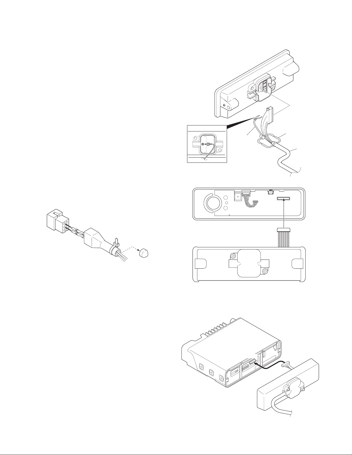
4. Use as Public Address Speaker
1. Remove the short plug from the 6-pin accessory connector on the rear of the radio. (Remove the jumpers as described in Section 3-1.)
2. Cut off the end of the protective cover, insert the speaker
cable into the protective cover, and insert it into pins 2 and
3.
3. Install the plug and protective cover on the accessory connector on the rear of the transceiver, then clamp the bottom of the protective cover with the supplied tie wrap.
4. If you remove jumper shorting pins 5 and 6, the 20W PA
(public address) voice signal is output from pins 2 and 3.
(Only when the PA or SP switch is on.)
5. If you use the radio with pins 5 and 6 shorted, the internal
speaker is available.
Notes :
•Relation ship between accessory connector (6-pins) connection and speaker output.
• When pins 5 and 6 are shorted; The internal speaker is
used.
• When pins 5 and 6 are open and output is from pins 2 and
3; The 20W external speaker is used.
Short plug
INSTALLATION
Rubber seal
Ground wire
KCT-22
Fig. 5-1
CN902
Display unit
3
Black lead
2
Black/White lead
Protective cover
Tie wrap
Cut
Speaker cable
Fig. 4
5. Single Control Head Remote Kit (KRK-9)
and Control Cable (KCT-22)
1. Lift the tab on the bottom of the transceiver, then pull the
panel away from the transceiver.
2. Remove the connector that binds the display unit to the
TX-RX unit.
3. As shown in Figure 5-1, make sure that the rubber seal is
placed above the cable, then plug the 11-pin connector
into the front panel PCB assembly.
4. Also, affix the ground wire to the front panel chassis, as
shown in Figure 5-1, with the supplied screw.
5. Choose the remote wire position (right side or left side),
then place the seal within the guide rail. Attach and secure the cover using the 2 binding screws.
6. Plug the 12-pin connector (from the rear panel) to the
CN902 socket on the display PCB, as shown in Figure 5-2.
7. Push and secure the panel into the chassis so that the 6
tabs on the top and bottom are securely fixed.
8. Plug the connector from the main panel into the CN703
socket (Figure 5-3).
9. Push and secure the main panel so that the 6 tabs on the
top and bottom of the panel are securely fixed.
8
Rear panel
Fig. 5-2
Fig. 5-3

INSTALLATION
TK-7150
6. Optional Board
6-1. Voice Scrambler Board Connection
■ Modification
1. Remove the cabinet and shielding cover from the trans-
ceiver.
2. Remove the panel.
3. Delete R798 and R866 on the TX-RX unit.
■ Connection
The functions of pins of CN701 on the foil side of the TX-
RX unit are shown in the figure.
Join the CN701 connector to the voice scrambler board via
the E37-0808-05 connector cable.
Note : You must setup the FPU.
The Voice Scrambler Board is connected subsequent
to the de-emphasis circuit.
CN701
TXI (MIC signal input)
TXO (MIC signal output)
RXI (Audio signal input)
AC (Scrambler control signal output)
BC1 (Scrambler code signal output 1)
BC2 (Scrambler code signal output 2)
BC3 (Scrambler code signal output 3)
BC4 (Scrambler code signal output 4)
NC (Non connection)
NC (Non connection)
RXO (Audio signal output)
PTOS (TX signal output)
8C (8V output)
E (Ground)
1
14
Voice
scrambler
6-2. ANI Board Connection
■ Modification
1. Remove the cabinet and shielding cover from the transceiver.
2. Remove the panel.
■ Connection
Join the CN700 connector to the ANI board via the E37-
0808-05 connector cable.
When the ANI board QE-2 is used, you must also use the
E37-1075-05 connector.
Note : You must setup the FPU.
1
14
ANI board
CN700
BUSY (Busy signal output)
EMG (Emergency signal output)
KEY (TX control signal input)
AUX (Emergency signal input)
INH (MIC mute signal input)
STON (Side tone input)
TCNT (Speaker mute signal input)
DATA (Data signal input)
E (Ground)
8C (8V output)
PTOA (PTT signal output)
DETO (Detected signal output)
NC (Non connection)
NC (Non connection)
Fig. 6-3 Component side of the TX-RX unit
Fig. 6-1 Foil side of the TX-RX unit
TX-RX UNIT
Component side
R866
R798
6-3. Example for Wire Connection
■ Picture (Scrambler board and ANI board)
Top view
Fig. 6-2
Front view
9

TK-7150
INSTALLATION
7.
Wiring of the Cable for Installing the
Built-in Type GPS Unit or Other PC Board
1. Loosen the 2 screws ( 1 ) to remove the D-sub 25-pin
connector.
2. Looses the 4 screws ( 2 ) to remove the Hardware fixture.
3. Remove the CN704 connector with the 6-pin lead wire.
4. Take out the Hardware fixture.
5. Cut the packing as shown in the illustratation.
7. Tighten the 4 screws to attach the Hardware fixture.
8. Tighten the 2 screws to fix attach D-sub 25-pin connector.
2
1
1
Packing
Cut out
Hareware
fixture
2
2
2
Packing
8. Horn Alert Function
The HR1 and HR2 pin of the accessory connector (25-pin)
on the rear of the transceiver is a relay and maximum current
is 1A.
8-1. Modification
1. Remove the cabinet and shielding cover from the trans-
ceiver.
2. Remove the panel.
3. Remove the short plug from the 6-pin accessory connec-
tor on the rear of the transceiver.
4. Delete R754 on the TX-RX unit.
Default Modification
R754 Enable Disable
State
HR1
HR2
HR1
HR2
R754
Cable of GPS unit
or other board
Cable styling
Fig. 7-1
TX-RX UNIT
Component side
Fig. 8
Fig. 7-2
10
Fig. 7-3

INSTALLATION
TK-7150
9. Special Instructions for Replacing the
Final Amplifier Q5
To replace the Final Amp Q5, ensure to follow the instruc-
tions given below:
9-1. C89 and C90 Positions
1. Ensure to solder C89 and C90 to securely contact Q5.
Note : The TX power may vary depending on the position
of C89 and C90.
9-2. Soldering
1. Ensure to solder C89 and C90 with the earth spring legs as
illustrated in Fig. 9-3.
Note : Use excessive solder to make it thicker than the
the electrodes of the chip.
2. Solder the terminals until the electrodes of the chip are
fully covered. (Refer to Fig. 9-1.)
Note : Use excessive solder to make it thicker than the
the electrodes of the chip. (Refer to Fig. 9-2.)
3. To solder the source side of C90 (FET Q5 source side),
solder the earth springs until they are fully covered. (Refer
to Fig. 9-4.)
C89,C90
C89,C90
The C89 and C90 must
contact securely the
Top view
Q5
C90
Side view
Solder Solder
Metal plate Metal plate
Solder
C90
PCB
Q5 package
C89
C89
ElectrodeConnect with solder
Fig. 9-3
NG
C89,C90
NG
Fig. 9-1
Fig. 9-2
OK
C89,C90
OK
The C89 and C90 must
contact securely
the Q5 package
C89
Q5
C90
OK
Top view
Fig. 9-4
11

TK-7150
CIRCUIT DESCRIPTION
1. Outline
The TK-7150 is a VHF/FM transceiver designed to operate
in the frequency range of 136 to 174MHz. Transmission output power is 50 watts. The maximum channel capacity is
128.
The unit consists of receiver, transmitter, phase-locked
loop (PLL) frequency synthesizer, and control circuits.
2. Receiver Circuit
The receiver is double conversion superheterodyne, designed to operate in the frequency range of 136MHz to
174MHz.
The receiver circuit consists of the following : 2-1 frontend circuit, 2-2 first mixer, 2-3 IF amplifier circuit, 2-4 audio
amplifier circuit, and 2-5 squelch circuit.
2-1. Front-end Circuit
The front-end circuit consists of former BPF (D209), RF
amplifier Q213, and latter BPF (D208 and D207). The BPF
covers frequency ranges 136 to 174MHz.
The latter BPF (D208 and D207) attenuates the unwanted
signals, and sends only the necessary signal to the first
mixer.
TX-RX UNIT (X57-657)
44.85MHz
IF AMP
Q207
IF AMP
Q206
SW
MCF (Wide)
XF201
MCF (Narrow)
XF202
D206D205
SW
2-2. First Mixer
The signal from the BPF is heterodyned with the first local
oscillator signal from the PLL frequency synthesizer circuit at
the first mixer DBM (Q209, Q210, Q211 and Q212) to become a 44.85MHz first intermediate frequency (IF) signal.
The first IF signal is fed through two monolithic crystal filters
(XF201; Wide, XF202; Narrow) to further remove spurious
signals.
2-3. IF Amplifier
The first IF signal is amplified by Q207 and Q206, and then
enters IC201 (FM system IC). The signal is heterodyned
again with a second local oscillator signal (44.395MHz) with
in IC201 to become a 455kHz second IF signal. The second
IF signal is fed through a 455kHz ceramic filters (CF201 and
CF203; Wide, CF202 and CF204; Narrow) to further eliminate
unwanted signal, and the quadrature detection circuit FM-detects the signal to produce a base-band signal and output it
from pin 9.
RX ANT
1st MIX DBM
Q209~212
BPF
D207,208
RF AMP
Q213
BPF
D209
RSSI
DET
SQL
W/N
Q205
SW
W/N
NOISE DET
D202
DET
IC714
AINR AOUTR
AMP
IC712 (A/2)
ASQ
RSSI
44.850MHz
FM SYSTEM IC : IC201
QUD
NOISE
AMP
Q204
SW
D203
W/N
DEO
IC713
CODEC
IC701
CPU
W/N
CF201,203
(Wide)
CF202,204
(Narrow)
455kHz
LPF
IC716 (A/2)
RXO RXI AFO
X201
44.395MHz
SW
D204
W/N
IC724 IC722
SW
Fig. 1 Receiver circuit
LPF
IC718
DAC
RF AMP
Q208
AMP
Buff AMP
Q513,515
RX
+44.85MHz
f
Q711 IC717
SW
MUTE
INT. SP
Q509
RX VCO
IC720
AF
AMP
12

CIRCUIT DESCRIPTION
TK-7150
2-4. Audio Amplifier
The recovered audio signal obtained from IC201 is amplified and anti-aliasing filtered by IC712 (A/2), inputted to the
AINR terminal of CODEC IC (IC713), and audio processed by
DSP (IC710). The processed audio signal from AOUTR terminal of IC713 is amplified and filtered by IC716 (A/2) to a sufficient level. The audio signal goes to an electronic volume
(IC718) and then it passes through the amplifier (IC722), to
the input of multiplexer IC (IC717), and is amplified to drive a
loudspeaker by an audio power amplifier (IC720). The audio
output can be provided to external 4Ω speaker through the 6pin ACC connector “ES1, ES2” on the rear panel. Q711 is a
mute switch.
2-5. Squelch Circuit
The output signal from IC201 enters FM IC again, then
passed through a band-pass filter.
The noise component output from IC201 is amplified by
Q204 and rectified by D202 to produce a DC Voltage corresponding to the noise level. The DC voltage is sent to the
analog port of the CPU (IC701).
IC201 outputs a DC voltage (RSSI) corresponding to the
input of the IF amplifier.
3. Transmitter Circuit
The transmitter circuit consists of the following circuits : 31 microphone circuit, 3-2 modulation level adjustment circuit,
3-3 driver and final power amplifier circuit, and 3-4 automatic
power control circuit.
3-1. Microphone Circuit
The signal from the microphone passes through the mute
switch (Q901) and is then routed to the Display unit (X54-340)
and TX-RX unit (X57-657). The signal then passes through
the AGC circuit to avoid signal distortion.
This circuit consists of IC714, D711, D712, Q707, and
Q708. The AGC is operated by controlling the + and – side
levels of amplitude using the current obtained by positive and
negative detection of the amplified audio signal.
The audio signal is amplified by IC712 (B/2), input to the
AINL terminal of CODEC IC (IC713), and audio processed by
DSP (IC710). The processed audio signal from the AOUTL
terminal of IC713 is amplified and filtered by IC716 (B/2), and
amplified by the summing amplifier IC719 (B/2).
3-2. Modulation Level Adjustment Circuit
The output of the summing amplifier IC719 (B/2) is passed
to an electronic volume (IC718) for maximum deviation adjustment before being applied to a varactor diode in the voltage controlled oscillator VCO.
3-3. Driver and Final Power Amplifier Circuit
The transmit signal is generated by the TX VCO (Q507),
amplified by Q513 and Q 515. This amplified signal is amplified by Q1, Q2, Q4, and Q5. And this signal is passed to the
FINAL stage. The RF power amplifier consists of MOS FET
transistor.
DISPLAY UNIT
(X54-340) TX-RX UNIT (X57-657)
IC714
(A/2)
MO
MB
VR700
SW
D-SUB
MI2
16.8MHz
IC717
Q507
TX VCO
VCXO
X501
AMP
DET
D711,712
Q513
Buff
AMP
Q901
SW
J901
MIC jack
MIC
TXI
IC712
(B/2)
AMP
AINL
Q707,708
ATT
TXO
Fig. 2 Microphone circuit
Q515
Buff
AMP
Q1
Drive
AMP
Q2
Drive
AMP
PC
IC2
(A/2)
CODEC
Q4
Drive
AMP
REF
AMP
DC
AMP
IC
D-SUB
Vcont
IC2
(B/2)
AOUTL
DI
Q5
Final
AMP
VR1
Power adj.
IC716
(B/2)
LPF
SW
IC717
D3
SW
D5 D6
IC719
(B/2)
AMP
DET DET
IC718IC713
DAC
ANT
IC715
(B/2)
DC
AMP
MO
MB
Fig. 3 Drive and final amplifier circuit
13

TK-7150
CIRCUIT DESCRIPTION
3-4. Automatic Power Control, Circuit and Transmitter
The automatic power control (APC) circuit stabilizes the
transmitter output power at a predetermined level, and consists of forward/reflected power detector circuits. The forward/reflected power detector circuits detects forward RF
power and reflected RF power to DC voltage, and consists of
a C coupling type detection circuit, RF detector D5/D6, and
DC amplifier IC2 (A/2).
The voltage comparator (IC2 B/2) compares the voltage
obtained by the above detected voltage with a reference voltage, set using the microprocessor and IC718 and IC715.
An APC voltage proportional to the difference between
the sensed voltage and the reference voltage appears at the
output of IC2. This output voltage controls the gate voltage
for the drive amplifier Q4 and final amplifier Q5, which keeps
the transmitter output power constant.
4. PLL Frequency Synthesizer
The transmit signal and the receive first L.O. signal are
generated by the PLL digital frequency synthesizer. The frequency synthesizer consists of a transmitter voltage controlled oscillator (TX VCO; Q507), a receiver voltage controlled oscillator (RX VCO; Q509), a buffer amplifier (Q513
and Q515), an RF amplifier (Q516), a low-pass filter (Q501,
Q503 and Q504), a PLL IC (IC501), and TX VCO/RX VCO
switches (Q510 and Q512).
In the transmit signal mode, an operating frequency programming data is sent to IC501, from the CPU (IC701), to set
the programmable counter within IC501. Q512 is turned on
to activate the TX VCO and the output signal of the TX VCO is
amplified by Q513 and Q516.
The signal is then divided down in frequency, at the programmable counter in IC501, to 5.0kHz or 6.25kHz, 7.5kHz
which is compared in phase with a 5.0kHz or 6.25kHz, 7.5kHz
reference signal, derived from 16.8MHz VCXO (X501) and a
MO
STR
12CL
LPF
Q501
Q503
Q504
Q507
Q509
IC501
8CL 8CL 8C 8T
Q513 Q515
TX VCO
SW
SWSW
RX VCO
PLL IC
CP
DT
IC701
CPU
Q512
Q510Q514
8CL
5C
EP
BUFF
AMP
Q516
AMP
LPF
Q518 Q519
SW SW
UL
BUFF
AMP
5C
D513
D514
SW
8R
X501
16.8MHz
VCXO 5C
MB
TX
RX
1/3360 or a 1/2688, 1/2240 fixed counter in IC501, at the
phase comparator in IC501. The VCXO operates at 16.8MHz
and its frequency stability is maintained within 2.5ppm (temperature range of –30 to +60 degrees).
The phase comparator output signal is fed into a low-pass
filter (Q501, Q503 and Q504) before being applied tot the TX
vco as a frequency control voltage. This low-pass filter’s
power is supplied by the DC/DC converter (Q502, Q505,
Q506, Q508, and Q511). If an unlock condition occurs in the
phase locked loop, this condition is detected by Q518 and
Q519. This cause the transmitter 8V supply cut off, resulting
in the prevention of an unauthorized transmission.
The transmitter modulation signals (processed Mic. audio
and sub-audible signalling) are applied to the TX VCO for frequency modulation.
In the receive mode, the VCO is substituted with Q509
(RX VCO) and it generates the receiver first local oscillator
signal according to the data sent from the CPU (IC701). The
basic operation of the synthesizer remains the same.
5. Control Circuit
The control circuit mainly consists of CPU, memory circuit, DSP circuit, and power supply circuit.
5-1. CPU
The CPU (IC701) controls the flash ROM (IC705), the DSP
(IC710), the receiver circuit, the transmitter circuit, the control circuit, and the display circuit and transfers data to or
from an external device.
5-2. Memory Circuit
IC705 has a flash ROM with a capacity of 4M bits that
contains the control program for the CPU, the signal processing program for DSP and data such as channels and operating
features.
This program can be easily written from an external devices. Data such as the operating status are programmed
into the EEPROM (IC704).
IC705IC704
EEPROM
IC103
Reset IC
X700
12.288MHz
Q700
BEAT
SHIFT
IC711
IC701
CPU
SW
Interface IC
INV
DSP
CODEC IC IC713
Flash ROM
IC703
232C driver
IC718
D/A IC
IC700/702
Shift register IC
IC706~709
IC710
14
Fig. 4 PLL circuit
Fig. 5 Control circuit

CIRCUIT DESCRIPTION
TK-7150
5-3. DSP Circuit
The DSP circuit filters transmit/receive audio signal and
encode/decode signalling (QT, DQT, MSK, DTMF, 2-Tone,
LTR ID). This circuit consists of IC710, IC706, IC707, IC708,
IC709 and IC713.
The receive audio signal is converted from analog to digital
by IC713 with a sampling frequency of 19.2kHz. The digitized
audio signal is sent to DSP (IC710) to process the signalling
signal and audio signal. The processed digital audio signal is
fed to CODEC (IC713), converted from digital to analog, and
the analog signal is output from pin 16 (AOUTR).
The transmit audio signal coming from IC714 (A/2) is amplified by IC712 (B/2), fed to pin 3 (AINL) of CODEC (IC713),
and converted from analog to digital at a sampling frequency
of 19.2kHz. The digitized transmit audio signal is AGC-processed, pre-emphasized and filtered at 300Hz to 3kHz by
DSP (IC710), and the resulting signal is feed back to CODEC
(IC713), and converted from digital to analog, and the analog
signal is output from pin 15 (AOUTL).
IC706, IC707, IC708 and IC709 are interface IC between
the CPU operated at 5.0V and the DSP operated at 3.3V.
5-4. Power Supply Circuit
The voltage is always applied from +B. D103 protects
IC102 (DFF) against overvoltage.
Pulses from power switch are input to the IC102 clock line
and the CPU (IC701). These clock pulses reverse the output
High (radio : turn off) → Low (radio : turn on), do not reverse
the output Low → High. The CPU (IC701) output the pulse to
IC102 set line to reverse the output Low → High.
IGN is input to the IC102 reset line and the CPU (IC701).
When the IC102 reset voltage rise, the output goes Low (ra-
dio : turn on). When IGN falls, the CPU (IC701) output the
pulse to IC102 set line to reverse the output Low → High
after the programmed time expire (Timed power off function).
If 24V is supplied to the radio by mistake, Q102 turns on,
Q101 turns off, the power is forced to be turned off.
This circuit consists of IC104 (8V), IC105 (5V), IC106
(3.3V), IC108 (3.3V) and IC107 (1.8V).
6. Display Circuit
The display unit consists of CPU (IC904), LCD assembly,
LED, and other components.
Channels are changed by the rotary switch (S1). The up/
down signals from the rotary switch enter the CPU (IC904),
and converted to a serial data signal, and are sent to the CPU
(IC701) in the TX-RX unit. The on/off signals of keys other
than the power switch, and the PTT and HOOK signals, are
converted to serial data and sent to the CPU (IC701) in the
TX-RX unit.
Data is displayed on the 12 digits and 3 digits dot matrix
alphanumeric display.
7. RS-232C Circuit
The RS-232C circuit connects the RS-232C serial port of a
personal computer directly to this model to perform FPU operation (Read and Write). The FPU operation can also be performed by connecting a programming cable (KPG-46) to the
local microphone on the front panel. The 232C driver IC
(IC703) changes the TTL-232C level. The firmware can only
be rewritten with the local microphone on the front panel.
+B
R112
D103
AVR
D104
SW
Q109,110
SW
D105
SW
D109
AVR
IGN PSW
IC102
DFF
Q112,113
SW
IC701
CPU
Q710
SW
D106SWD102
Q111
SW
Q108
SW
Q713
SW
Fig. 6 Power supply circuit
SW
Q102
SW
Q103
SW
Q101
SW
SB
LCD
PTT
D915
RX LED
D912
TX LED
Q903
SW
SB
D910
D909D908
SW
Key back lamp
HK
SW
Q907
SW
Q906
D907
REF
D911D913D914
SWQ904
IC904
CPU
Q908
Q902
SW
X901
12MHz
5V
RST
PF1
DM
MIC
1
Rotary SW
AVR
IC901
PF2 PF3 PF4 PF5 PF6
AF VR
SB
HK
PTT
J901
BEAT SHIFT
POWER
SW
E
ME
8LC
8
PSW
SB
RST
IRS
ES2
MIC
INT SP
Fig. 7 Display circuit
15

TK-7150
SEMICONDUCTOR DATA
1. CPU : 30620M8A-5H1GP (TX-RX Unit IC701)
1-1. Pin Function
Pin No. Name I/O Function
1 I/O Go to port check mode
L : Port check mode, H : User mode
2WNOWide/Narrow H : Narrow, L : Wide
3 8RC O 8R Control H : 8R on, L : 8R off
4 INTx O INT Request to DSP L : INT request
5 STR O VCO TX/RX H : TX VCO, L : RX VCO
6 BYTE +5V
7 CNVss GND
8 8TC O 8T Control H : 8T on, L : 8T off
9 SFT O Beat Shift H : SFT on, L : SFT off
10 RESET CPU Reset
11 Xout 12.288MHz
12 Vss GND
13 Xin 12.288MHz
14 Vcc +5V
15 NMI I Not Used
16 IGN I Ignition Sense
H : IGN. Sense off, L : IGN. Sense on
17 PSI I Power Down Det L : Power down det
18 LD O D/A Converter LD
19 CP O PLL IC Clock
20 EP O PLL IC Enable
21
22 DT O Common Data
23 CK O Common Clock
24 SOE O Shift Register 1 OE
25 STB1 O Shift Register 1 Strobe
26 AI4 I AUX Input No.4 H : Inactive, L : Active
27 RXD2 I Head Comm (RXD)
28 TXD2 O Head Comm (TXD)
29 TXD1 O Acc com2 (TXD)
30 RXD1 I Acc com2 (RXD)
31 AI3 I AUX Input No.3 H : Inactive, L : Active
32 AI2 I AUX Input No.2 H : Inactive, L : Active
33 TXD0 O Acc com1 (TXD)
34 RXD0 I Acc com1 (RXD)
35 AI1 I AUX Input No.1 H : Inactive, L : Active
36 O Not Used
37 RDY I Hardware BUS Wait Control
38 ALE O Cannot Use (Address Latch)
CONTROL
O Connect Codec TX Out to speaker line
H : Connect, L : Disconnect
Pin No. Name I/O Function
39 HOLD I Cannot Use (BUS Hold)
40 HLDA O Cannot Use (BUS Hold Status)
41 BCLK O Cannot Use (Sys Clock Output)
42 RD O Flash ROM : RD, DSP : HDS1
43 BHE O Cannot Use (BUS High Enable)
44 WR O Flash ROM : WR, DSP : HDS2
45 SBC O SB Control H : SBC off, L : SBC on
46 AM O
47 HCS O DSP HCS
48 CS0 O Flash CS
49~59 A19~A9 O Cannot Use (Flash ROM Address BUS)
60 Vcc +5V
61 A8 O Cannot Use (Flash ROM Address BUS)
62 Vss GND
63~70 A7~A0 O Cannot Use (Flash ROM Address BUS)
71 PTO O Scrambler TX/RX Control H : RX, L : TX
72 PSW I
73 Inty I INT Request from DSP L : INT request
74 RS O DSP Reset H : DSP reset
75 SCL O EEPROM Clock
76 SDA I/O EEPROM Data
77 KEY I
78 STB2 O Shift Register 2 Strobe
79~86 D7~D0 Cannot Use (Flash ROM Data BUS)
87 PDET I Power Det Level
88 CDET I Power Current Det Level
89 TEMP1 I Power Temp1 Level
90 TEMP2 I Power Temp2 Level
91 ASQ I Analog Squelch Level
92 RSSI I RSSI Level
93 UL I Unlock Level
94 Avss GND
95 I Not Used
96 Vref +5V
97 Avcc +5V
98 AUX I Emergency Channel Request from ANI
99 INH I Audio Inhibit from ANI board
100 TCNT I Tone Control from ANI board
Audio Mute H : SP mute, L : SP unmute
Pow. Switch Det H : Inactive, L : Active
TX Request from ANI board L : TX request
board L : Channel request
H : SP unmute, L : SP mute
L : Board tone output request
16

SEMICONDUCTOR DATA
TK-7150
2. Shift Register 1 : BU4094BCFV (TX-RX Unit IC702)
2-1. Pin Function
Pin No. Port Name
1
STROBE
2
SERIAL IN
3 CLOCK CLK I
4Q1 MI2 O External Mic Mute
5Q2DIOExternal Data Line Mute
6Q3SPOFront SP/EXT SP Change
7Q4 HRO
8 VSS VSS GND
9QsQsONo Connect
10 Qs’ Qs’ O No Connect
11 Q8 AO4 O AUX Output No.4
12 Q7 AO3 O AUX Output No.3
13 Q6 AO2 O AUX Output No.2
14 Q5 AO1 O AUX Output No.1
15 OUTPUT SOE I From CPU SOE (Pin No.24)
ENABLE L → Inactive, H → Active
16 VDD VDD +5V
Name I/O Function
STB1 I From CPU STB1 (Pin No.25)
DATA I
From CPU Common Data (Pin No.22)
From CPU Common Clock (Pin No.23)
L : Mute, H : Unmute
L : Mute, H : Unmute
L : Front SP, H : External SP
Horn Alert L : Relay off, H : Relay on
H : AUX Out No.4 on, L : AUX Out No.4 off
H : AUX Out No.3 on, L : AUX Out No.3 off
H : AUX Out No.2 on, L : AUX Out No.2 off
H : AUX Out No.1 on, L : AUX Out No.1 off
3. Shift Register 2 : BU4094BCFV (TX-RX Unit IC700)
3-1. Pin Function
Pin No. Port Name
1 STROBE STB2 I From CPU STB1 (Pin No.21)
2
SERIAL IN
3 CLOCK CLK I
4Q1 BC1 O Scrambler Code 1 (For SCR)
5Q2 BC2 O Scrambler Code 2 (For SCR)
6Q3 BC3 O Scrambler Code 3 (For SCR)
7Q4 BC4 O Scrambler Code 4 (For SCR)
8 VSS VSS GND
Name I/O Function
DATA I
From CPU Common Data (Pin No.22)
From CPU Common Clock (Pin No.23)
L : SCR Code1 off, H : SCR Code1 on
L : SCR Code2 off, H : SCR Code2 on
L : SCR Code3 off, H : SCR Code3 on
L : SCR Code4 off, H : SCR Code4 on
Pin No. Port Name
9QsQsONo Connect
10 Qs’ Qs’ O No Connect
11 Q8 AC O Scrambler ON/OFF (For SCR)
12 Q7 BUSY O Channel Busy (For ANI)
13 Q6 EMG O Emergency ON/OFF (For ANI)
14 Q5 PTO O PTT Output (For ANI)
15 OUTPUT SOE GND
16 VDD VDD +5V
4. D/A Converter : M62364FP (TX-RX Unit IC718)
4-1. Pin Function
Pin No.
1 Vin1 I AF Volume First IN
2 Vout1 O AF Volume First OUT
3 Vout2 O AF Volume Second OUT
4 Vin2 I AF Volume Second IN (From DAC Pin No.2)
5 VDD +5V
6LDOFrom CPU LD(Pin No.18)
7CKOFrom CPU Common Clock (Pin No.23)
8DTOFrom CPU Common Data (Pin No.22)
9 Vin3 I GND
10 Vout3 O Tune Varicap
11 Vout4 O Side Tone Out
12 Vin4 I Side Tone (From Option Board)
13 Vin5 I
14 Vout5 O Max Deviation
15 Vout6 O
16 Vin6 I DQT Balance
17 Do O Open
18 VDAref I
19 Reset I +5V
20 GND GND
21 Vin7 I +5V
22 Vout7 O Frequency Adjust
23 Vout8 O Auto Power Control
24 Vin8 I +5V
Name I/O Function
L : Scrambler on, H : Scrambler off
L : Busy, H : Not Busy
L : Emergency on, H : Emergency off
L : PTT on, H : PTT off
ENABLE
Name I/O Function
17

TK-7150
SEMICONDUCTOR DATA
5. Display CPU : 30622M4A-443GP (Display Unit IC904)
5-1. Pin Function
Pin No. Name I/O Function
1 DISP O LCD Display ON/OFF L : On, H : Off
2~5 O Not used
6 BYTE GND
7 CNVss GND
8ONot used
9 SFT O Beat Shift L : Shift off, H : Shift on
10 RESET CPU Reset
11 Xout 12.0MHz
12 Vss GND
13 Xin 12.0MHz
14 Vcc +5V
15 NMI I Not used
16~19 O Not used
20 MIC O Mic Mute L : Mute, H : Unmute
21,22 O Not used
23 DM I/O Mic Keypad Data
24 O Not used
25 BLC O
26 O Not used
27 RXD2 I Body Comm (RXD)
28 TXD2 O Body Comm (TXD)
29 TXD1 O PC Comm (TXD)/connect to PTT
30 RXD1 I Open (RXD)
31 I Not used
32 O Not used
33 TXD0 O Open (TXD)
34 RXD0 I PC Comm (RXD)/connect to HOOK
35 HOOK I HOOK/connect to RXD0
36 PTT I PTT/connect to TXD1
37 O Not used
38 BCK1 O PF Key Backlight Control L : Off, H : On
39 PF1 I PF1 Key Input
40 PF2 I PF2 Key Input
Mic Keypad Backlight Control L : Off, H : On
Pin No. Name I/O Function
41 PF3 I PF3 Key Input
42 PF4 I PF4 Key Input
43 PF5 I PF5 Key Input
44 PF6 I PF6 Key Input
45~49 O Not used
50 BCK2 PF Key Backlight Control L : Off, H : On
51 TP3 I Head Check Mode L : Head check mode,
H : Not go to head check mode
52~56 O Not used
57 BUSY O BUSY LED L : Off, H : On
58 TX O TX LED L : Off, H : On
59 O Not used
60 Vcc +5V
61 O Not used
62 Vss GND
63~66 O Not used
67 RSW4 I Rotary SW4
68 RSW3 I Rotary SW3
69 RSW2 I Rotary SW2
70 RSW1 I Rotary SW1
71~81 O Not used
82 LEDK O LCD Back Light Control L : Off, H : On
83 DO O LCD Data Output
84 DI I LCD Data Input
85 CL O LCD Clock
86 CE O LCD CS
87~92 O Not used
93 VOL I Audio Volume Input
94 AVss GND
95 O Not used
96 AVref +5V
97 AVcc +5V
98~100 O Not used
18

SEMICONDUCTOR DATA
6. DSP : 320VC5402PGE (TX-RX Unit IC710)
6-1. Pin Function
Pin No. Name I/O Function
1,2,12,15,
35~38,
71~74,80,
90,110,126,
143,144
6,58,69,81, HD0~HD7 I/O HPI data bus
95,120,124,
135
5,7~11,105,
107~109,
131~134,
136~141,
13 HAS I HPI address strobe (Pull up)
17 HCS I HPI chip select
18 HR/W I HPI read/write
19 READY I Data ready (Pull up)
20 PS O Not used (No connect)
21 DS O Not used (No connect)
22 IS O Not used (No connect)
23 R/W O Not used (No connect)
24 MSTRB O Not used (No connect)
25 IOSTRB O Not used (No connect)
26 MSC O Not used (No connect)
27 XF O CODEC control
28 HOLDA - Not used (No connect)
29 IAQ - Not used (No connect)
30 HOLD I Hold (Pull up)
31 BIO I Serial data synchronize input
32 MP/MC I Not used (Pull down)
39 HCNTL0 I HPI control 0
41 BCLKR0 I
42 BCLKR1 -
43 BFSR0 I Frame sync. for receiver output
44 BFSR1 I Not used (No connect)
45 BDR0 I Serial data receive input
46 HCNTL1 I HPI control 1
47 BDR1 - Not used (No connect)
48 BCLKX0 I
49 BCLKX1 O Not used (No connect)
51
NC1~NC18
A0~A19 O Not used (No connect)
HINT/TOUT1
- Not used (No connect)
(H : power down, L : active)
Receive clock output (SCLK : 614.4kHz)
Master clock output (MCLK : 4.9152MHz)
(LRCK : 19.2kHz)
Transmit clock input (SCLK : 614.4kHz)
O Interrupt for Host CPU/Boot mode
select (Pull up)
TK-7150
Pin No. Name I/O Function
53 BFSX0 I Frame sync.for transmitter input
(LRCK : 19.2kHz)
54 BFSX1 I Not used (No connect)
55 HRDY - Not used (No connect)
59 BDX0 O Serial data transmit output
60 BDX1 - Not used (No connect)
61 IACK - Not used (No connect)
62 HBIL I Byte identification (HPI)
63 NMI I Not used (Pull up)
64 INT0 I Command interrupt from Host CPU
65 INT1 I Not used (Pull up)
66 INT2 I Boot mode select (Pull up)
67 INT3 I Not used (Pull up)
77 CLKMD1 I Clock mode select (Pull down)
78 CLKMD2 I Clock mode select (Pull up)
79 CLKMD3 I Clock mode select (Pull down)
82 TOUT0 - Not used (No connect)
83 EMU0 I/O Emulator 0 (to JTAG connector)
84
85 TDO O
86 TDI I Test data input (to JTAG connector)
87 TRST I Test reset (to JTAG connector)
88 TCK I Test clock (to JTAG connector)
89 TMS I
92 HPIENA I Not used (Pull up)
94 CLKOUT O Not used (No connect)
96 X1 - 12.288MHz (System clock)
97 X2/CLKIN - 12.288MHz (System clock)
98 RS I DSP reset input
99~104, D0~D15 - Not used (No connect)
113~119,
121~123
127 HDS1 I HPI data strobe1 (Pull up)
129 HDS2 I HPI data strobe2 (Pull down)
3,14,34,40, Vss - GND
50,57,70,
76,93,106,
111,128
4,33,56, DVDD - VDD for I/O pins (+3.3V)
75,112,130
16,52,68, CVDD - VDD for core CPU (+1.8V)
91,125,142
EMU1/OFF
I/O Emulator 1 (to JTAG connector)
Test data output (to JTAG connector)
Test mode select (to JTAG connector)
19

TK-7150
COMPONENTS DESCRIPTION
1. Display Unit (X54-3400-10)
Ref. No. Part Name Description
IC901 IC Voltage regulator
IC902 IC Voltage detector
IC904 IC CPU
Q901 FET MIC switch
Q902 FET DC switch
Q903 Transistor Current driver
Q904~908 Transistor DC switch
Q909,910 Transistor Inverter
Q911 Transistor DC switch
D902~906 Diode Surge protector
D907 Zener diode Voltage reference
D908~911 LED Key backlight
D912 LED TX light
D913,914 LED Key backlight
D915 LED RX light
D916 Zener diode Surge protector
D917 Varistor Current protector
D918 Zener diode Surge protector
2. TX-RX Unit (X57-6570-10)
Ref. No. Part Name Description
IC1 IC Not used
IC2 IC DC amplifier
IC101 IC Voltage detector
IC102 IC D flip-flop
IC103 IC Voltage detector
IC104~108 IC Voltage regulator
IC201 IC FM IF system
IC202 IC Multiplexer
IC501 IC PLL
IC700 IC Shift register
IC701 IC CPU
IC702 IC Shift register
IC703 IC RS232C transceiver
IC704 IC EEPROM
IC705 IC Flash ROM
IC706 IC Bus transceiver
IC707~709 IC OR gate
IC710 IC DSP
Ref. No. Part Name Description
IC711 IC Inverter
IC712 IC AF amplifier
IC713 IC CODEC
IC714 IC MIC amplifier/AGC
IC715 IC Buffer amplifier
IC716 IC Anti-aliasing filter
IC717 IC Multiplexer
IC718 IC D/A converter
IC719 IC AF amplifier
IC720 IC Audio power amplifier
IC721 IC DC amplifier
IC722 IC AF amplifier
IC723 IC Voltage regulator
IC724 IC Multiplexer
IC725 IC Voltage detector
Q1,2 Transistor RF amplifier
Q4 FET Drive amplifier
Q5 FET Final amplifier
Q101 Transistor DC switch
Q102 Transistor Switch
Q103 FET DC switch
Q104~113 Transistor DC switch
Q201~203 Transistor W/N switch
Q204 Transistor Noise amplifier
Q205 Transistor W/N switch
Q206 Transistor IF amplifier
Q207 Transistor Pre IF amplifier
Q208 Transistor RF amplifier
Q209~212 FET Mixer
Q213 Transistor RF amplifier
Q501 Transistor Active filter
Q502 FET Oscillator
Q503,504 Transistor Active filter
Q505,506 Transistor DC switch
Q507 FET TX oscillator
Q508 Transistor AVR
Q509 FET RX oscillator
Q510 Transistor TX/RX switch
Q511 Transistor Ripple filter
Q512 Transistor TX/RX switch
20

COMPONENTS DESCRIPTION
TK-7150
Ref. No. Part Name Description
Q513 Transistor Buffer amplifier
Q514 Transistor Inverter
Q515 Transistor Buffer amplifier
Q516 Transistor Amplifier
Q517 Transistor Ripple filter
Q518~520 Transistor DC switch
Q521 Transistor Inverter
Q700 FET DC switch
Q701~706 Transistor DC switch
Q707,708 Transistor MIC gain switch
Q709 Transistor Inverter
Q710,711 Transistor DC switch
Q712,713 FET DC switch
Q714 Transistor DC switch
Q716 Transistor DC switch
Q719,720 Transistor DC switch
D1 Zener diode Surge protector
D2 Zener diode Voltage protection
D3,4 Diode ANT switch
D5,6 Diode RF detector
D7 Diode Temperature compensation
D11 Diode Surge protector
D101 Diode Protection of reverse connection
D102,103 Zener diode Voltage reference
Ref. No. Part Name Description
D104~106 Diode DC switch
D108 Diode Surge protector
D109 Zener diode Voltage reference
D201 Diode DC switch
D202 Diode Noise detection
D203~206 Diode Wide/Narrow switch
D207~209 Varicap BPF tuning
D501~508 Varicap Frequency control
D509,510 Diode Voltage doubler
D511 Varicap Modulator
D512 Zener diode Voltage reference
D513,514 Diode RF switch
D515 Diode DC switch
D700~703 Diode Surge protector
D704 Diode Voltage reduction
D705~709 Diode Surge protector
D710 Zener diode Surge protector
D711,712 Diode AF detector
D714 Diode DC switch
D715 Zener diode Surge protector
D785~790 Zener diode Surge protector
D791 Varistor Current protector
D793 Varistor Current protector
D794 Diode Delay
21

TK-7150
TERMINAL FUNCTION
1. Display Unit (X54-3400-10) (A/2)
Pin No.
Name Description
CN901 (To remote speaker)
1 IRS BTL output for remote speaker output.
2 ES2 BTL output for remote speaker output.
CN902 (To TX-RX unit)
1ME MIC ground.
2 MIC MIC signal output.
3E Ground.
4 RESET Reset signal input.
5 TXD Serial data input.
6 RXD Serial data output.
7E Ground.
8 PSW Power switch control signal output.
9SB Power input after power switch (13.6V±15%).
10 IRS BTL input for remote speaker output.
11 ES2 BTL input for remote speaker output.
CN905 (To LCD assy)
1E Ground.
2 VCC 5V.
3CE Enable output for LCD driver.
4CL Clock output for LCD driver.
5DI Data output for LCD driver.
6DO Not used.
7 DISP Display control signal output. “L” : Display off
8 LEDA Power output for LCD backlight.
9 LEDK Ground for LCD backlight. “L” : Backlight on
10 NC Non connection.
CN906 (To Display unit B/2 : CH SW)
1E Ground.
2P4 SW position signal input 4.
3P3 SW position signal input 3.
4P2 SW position signal input 2.
5P1 SW position signal input 1.
J901 (MIC jack)
1DM Serial data input for keypad MIC.
2 MIC MIC signal input.
3 PTT PTT signal input. “L” : TX, “OPEN” : RX
Serial data output.
4SB Power output after power switch (13.6V±15%).
Pin No.
Name Description
5HK
6ME MIC ground.
7E Ground.
8 BLC
Hook signal input. “L” : On hook, “H” : Off hook
Serial data input.
MIC backlight control signal output. “H” : On, “L” : Off
2. Display Unit (X54-3400-10) (B/2)
Pin No.
Name Description
W1 (To Display unit A/2)
1P1 SW position signal output 1.
2P2 SW position signal output 2.
3P3 SW position signal output 3.
4P4 SW position signal output 4.
5E Ground.
3. TX-RX Unit (X57-6570-10)
Pin No.
Name Description
CN700 (To ANI board)
1 BUSY
2 EMG Emergency signal output.
3 KEY TX control signal input.
4 AUX Emergency signal input.
5 INH MIC mute signal input. “L” : Mute
6 STON Side tone input.
7 TCNT Speaker mute signal input. “L” : Unmute
8 DATA Data signal input.
9E Ground.
10 8C
TX sens signal output
Conventional “H” : Not TX, “L” : TX
LTR “H” : Not Link complete, “L” : Link complete
“L” : Emergency function is operated,
“H” : Emergency function is not operated
L ≤ 0.05V, H ≥ 4.6V/30kΩ load
Active low with 47kΩ pull-up to 5V
L ≤ 0.8V, H ≥ 2.5V
Active low with 47kΩ pull-up to 5V
L ≤ 0.8V, H ≥ 2.5V
Active low with 47kΩ pull-up to 5V
L ≤ 0.8V, H ≥ 2.5V
L ≤ 0.8V, H ≥ 2.5V
8V. (CN700 No.10 + CN701 No.13 = 100mA Max.)
66

TERMINAL FUNCTION
TK-7150
Pin No.
Name Description
11 PTOA PTT signal output. “L” : PTT on, “H” : PTT off
L ≤ 0.05V, H ≥ 4.6V/30kΩ load
12 DETO Detected signal output. DC coupled. Zo ≤ 100Ω
Wide : 0.8Vp-p typ., Narrow : 0.7Vp-p typ.
(Standard modulation)
13 NC Non connection.
14 NC Non connection.
CN701 (To voice scrambler)
1 TXI
2 TXO MIC signal output (Capacitor-coupled). Zo = 1kΩ
3 RXI
4AC
5 BC1 Scrambler code signal output 1.
6 BC2 Scrambler code signal output 2.
7 BC3 Scrambler code signal output 3.
8 BC4 Scrambler code signal output 4.
9NC Non connection.
10 NC Non connection.
11 RXO Audio signal output. DC coupled. Zo ≤ 100Ω
12 PTOS TX signal output. “L” : TX, “H” : Not TX
13 8C
14 E Ground.
MIC signal input (Capacitor-coupled). Zin = 100kΩ
Wide : 85mVp-p typ., Narrow : 85mVp-p typ.
(Standard modulation)
Audio signal input (Capacitor-coupled). Zin = 27kΩ
Wide : 1.3Vp-p typ., Narrow : 1.1Vp-p typ.
(Standard modulation)
Scrambler control signal output. “L” : On, “H” : Off
L ≤ 0.05V, H ≥ 4.6V/30kΩ load
L ≤ 0.05V, H ≥ 4.6V/30kΩ load
L ≤ 0.05V, H ≥ 4.6V/30kΩ load
L ≤ 0.05V, H ≥ 4.6V/30kΩ load
L ≤ 0.05V, H ≥ 4.6V/30kΩ load
Wide : 1.3Vp-p typ., Narrow : 1.1Vp-p typ.
(Standard modulation)
L ≤ 0.05V, H ≥ 4.6V/30kΩ load
8V. (CN700 No.10 + CN701 No.13 = 100mA Max.)
CN703 (To Display unit A/2)
1ME MIC ground.
2 MIC MIC signal input.
3E Ground.
4 RESET Reset signal output.
5 TXD Serial data output.
Pin No.
Name Description
6 RXD Serial data input.
7E Ground.
8 PSW Power switch control signal input.
9SB Power output after power switch (13.6V±15%).
10 IRS BTL output for remote speaker output.
11 ES2 BTL output for remote speaker output.
CN704 (To ACC 6-pin connector)
1 IRS Remote speaker switch.
2 ES1 BTL output for external speaker A.
3 ES2 BTL output for external speaker A.
4 OS1 BTL output for external speaker B (PA).
5 OS2 BTL output for external speaker B (PA).
6 IGN Ignition sense input.
J700 (ACC 25-pin)
1NC Non connection.
2 RXD2 * Serial data input 2. RS-232C level. Input voltage
range = ± 30V max. L ≤ 0.4V, H ≥ 2.4V. Zi ≥ 5kΩ
3 TXD2 * Serial data output 2. RS-232C level.
L ≤ –5V, H ≥ 5V/3kΩ load. Zo ≤ 2kΩ
4 AO3 Auxiliary output 3 (Programmable). Active low
open collector (100mA max.) (Default none).
L ≤ 0.3V
5DI Data signal input (Capacitor-coupled). Z ≥ 10kΩ
6 MI2
7E Ground.
8 AO2 Auxiliary output 2 (Programmable). Active low
9 TXD3 ** Serial data output 3.
10 RXD3 ** Serial data input 3.
11 E Ground.
12 AI4 Auxiliary input 4 (Programmable). Active low
13 AI2 Auxiliary input 2 (Programmable). Active low
External MIC input (Capacitor-coupled). Z = 600Ω
with 10kΩ pull-up to 5V (100mA max.) (Default
none). L ≤ 0.3V, H ≥ 4.8V
L ≤ 0.7V, H ≥ 4.2V/25kΩ load. Zo ≤ 1kΩ
Input voltage range = +5/0 max. L ≤ 0.8V, H ≥ 4.2V.
with 47kΩ pull-up to 5V (Default none).
L ≤ 0.8V, H ≥ 2.5V
with 47kΩ pull-up to 5V (Default none).
L ≤ 0.8V, H ≥ 2.5V
67

TK-7150
TERMINAL FUNCTION / OPTIONS
Pin No.
Name Description
14 SB Power output after power switch. 13.6V± 15%,
1.1A max. at 25°C, 0.8A max. at 60°C
15 TXS TX sense signal output. Active high with 10kΩ
pull-up to 5V. L ≤ 0.3V, H ≥ 4.8V
16 HR1 Horn alert signal output 1. 1A max.
17 AFO Filtered audio output (DC coupled). Zo ≤1kΩ
PA : MIC signal output. 0.65Vp-p typ. (1kHz/5mV input)
RX : RX low level output. Wide : 1.3Vp-p typ.,
Narrow : 1.1Vp-p typ. (Standard modulation)
18 E Ground.
19 DEO Detected signal output (Capacitor-coupled).
20 AO1 Auxiliary output 1 (Programmable). Active low
with 10kΩ pull-up to 5V (100mA max.) (Default
none). L ≤ 0.3V, H ≥ 4.8V
21 AI1 Auxiliary input 1 (Programmable). Active low
with 47kΩ pull-up to 5V (Default none).
L ≤ 0.8V, H ≥ 2.5V
22 AO4 Auxiliary output 4 (Programmable). Active low
open collector (100mA max.) (Default none).
L ≤ 0.3V
23 HR2
24 AI3 Auxiliary input 3 (Programmable). Active low
25 ME MIC ground.
Horn alert signal output 2. 1A max. (Default ground)
with 47kΩ pull-up to 5V (Default none).
L ≤ 0.8V, H ≥ 2.5V
1. KES-5 (External Speaker)
1-1. External View
1-2. Parts List
New
Ref. No.
parts
✽ A62-1050-08 Panel assy
✽ A82-0050-08 Rear panel
✽ B43-1142-08 Badge Panel
✽ E30-3479-08 Speaker cable
✽ G13-1923-08 Cushion SP front
✽ G53-1553-08 Packing Rear panel
✽ J29-0699-08 Bracket
✽ N08-0551-08 Dressed screw Bracket
✽ N99-2031-08 Screw set Acc
✽ T07-0741-08 Speaker
Parts No.
Description
✽ : New parts
2. KRK-9 (Single Control Head Remote Kit)
1-1. External View
16
1514
17
* and ** : Pair
4. ACC 6-pin Connector
Pin No.
68
Name Description
1 IGN Ignition sense input.
2 OS2 BTL output for external speaker B (PA).
3 OS1 BTL output for external speaker B (PA).
4 ES2 BTL output for external speaker A.
5 ES1 BTL output for external speaker A.
6 RS1 Remote speaker switch.
1918
20
24232221
25
13121110987654321
1-2. Parts List
New
Ref. No.
parts
6
3
2
5
1
4
Parts No. Description
✽ A62-1039-02 Panel Body
✽ A82-0049-02 Rear panel Head
✽ E37-1008-05 Lead wire with connector 11P
✽ F07-1865-03 Mold cover For cable
✽ G02-0895-04 Earth spring Cable GND
✽ G53-1552-03 Packing Rear panel
✽ J21-8447-04 Hardware fixture Panel
✽ J29-0698-03 Bracket Acc
✽ N08-0550-04 Dressed screw Acc
N87-3008-45 Brazier head taptite screw Panel
✽ N99-2032-05 Screw set Acc
✽ : New parts

TK-7150
KENWOOD CORPORATION
2967-3, Ishikawa-machi, Hachioji-shi, Tokyo 192-8525, Japan
KENWOOD U.S.A. CORPORATION
P. O. BOX 22745, 2201 East Dominguez Street, Long Beach, CA 90801-5745, U.S.A.
KENWOOD ELECTRONICS CANADA INC.
6070 Kestrel Road, Mississauga, Ontario, Canada L5T 1S8
KENWOOD ELECTRONICS DEUTSCHLAND GMBH
Rembrücker Str. 15, 63150 Heusenstamm, Germany
KENWOOD ELECTRONICS BELGIUM N.V.
Leuvensesteenweg 248 J, 1800 Vilvoorde, Belgium
KENWOOD ELECTRONICS FRANCE S.A.
13, Boulevard Ney, 75018 Paris, France
KENWOOD ELECTRONICS U.K. LIMITED
KENWOOD House, Dwight Road, Watford, Herts., WD18 9EB United Kingdom
KENWOOD ELECTRONICS EUROPE B.V.
Amsterdamseweg 37, 1422 AC Uithoorn, The Netherlands
KENWOOD ELECTRONICS ITALIA S.p.A.
Via G. Sirtori, 7/9 20129 Milano, Italy
KENWOOD IBERICA S.A.
Bolivia, 239-08020 Barcelona, Spain
KENWOOD ELECTRONICS AUSTRALIA PTY. LTD.
(A.C.N. 001 499 074)
16 Giffnock Avenue, Centrecourt Estate, North Ryde, N.S.W. 2113 Australia
KENWOOD ELECTRONICS (HONG KONG) LTD.
Unit 3712-3724, Level 37, Tower one Metroplaza, 223 Hing Fong Road, Kwai Fong, N.T., Hong Kong
KENWOOD ELECTRONICS TECHNOLOGIES(S) PTE LTD.
Sales Marketing Division
1 Ang Mo Kio Street 63, Singapore 569110
 Loading...