

Page 1

INSTRUCTION MANUAL
FM DUAL BANDER TH-F7
144/ 430 MHz FM DUAL BANDER
TH-F7A
© B62-1899-00 (M)
09 08 07 06 05 04 03 02 01 00
Page 2
THANK YOU
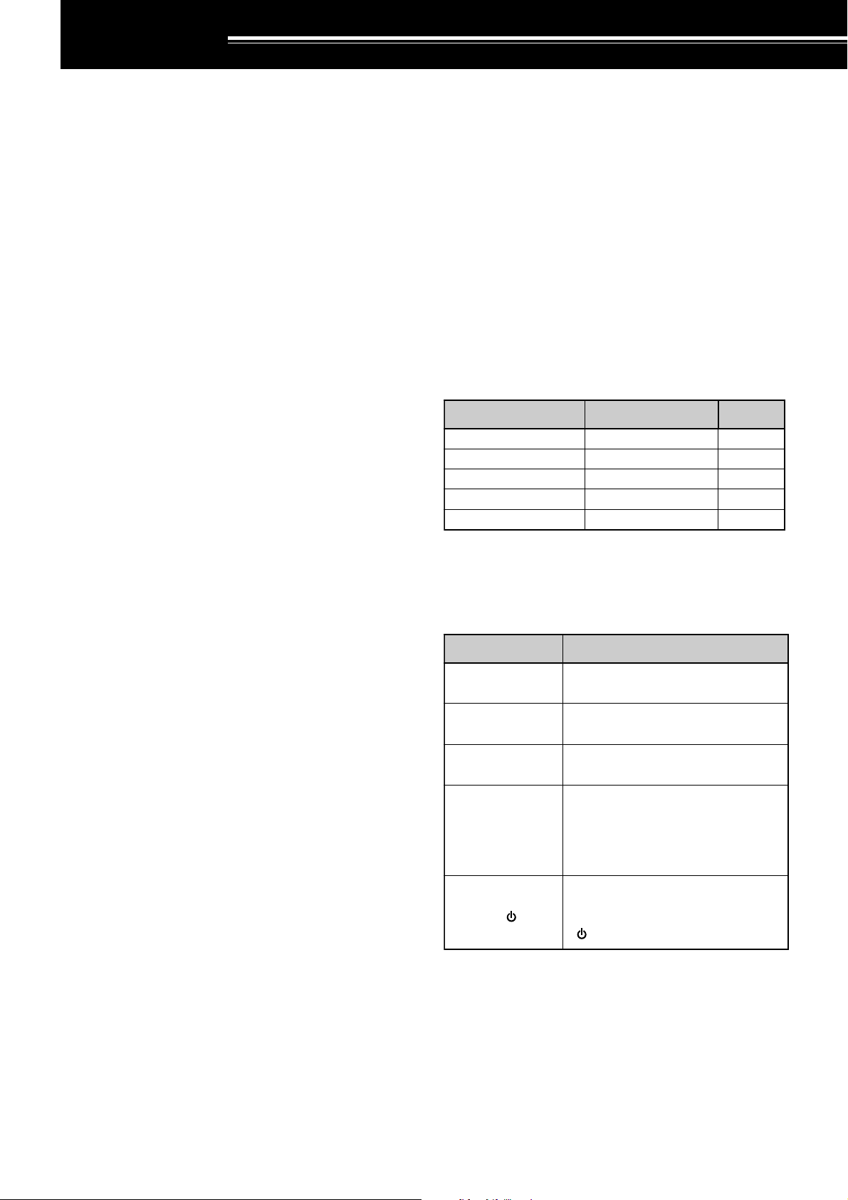
yrosseccA rebmuNtraP ytitnauQ
koohtleBXX-3260-92J1
annetnAXX-9870-09T1
partSXX-2430-96J1
)31-TB(esacyrettaBXX-7393-20A1
launaMnoitcurtsnIXX-9981-26B1
noitcurtsnI oDottahW
sserP ]YEK[ .esaelerdnasserP YEK .
sserP
]1YEK[ , ]2YEK[ .
sserP 1YEK esaeler,yliratnemom
1YEK sserpneht, 2YEK .
sserP
]YEK[)s1( .
dlohdnasserP YEK arofnwod
.dnoces
sserP
]2YEK[+]1YEK[ .
dlohdnasserP 1YEK neht,nwod
sserp 2YEK eromeraerehtfI.
dlohdnasserp,syekowtnaht
ehtlitnunrutniyekhcaenwod
.desserpneebsahyeklanif
sserP
][+]YEK[ .
sserp,FFOreviecsnartehthtiW
dlohdna YEK NOhctiwsneht,
gnisserpybrewopreviecsnarteht
][ .)REWOP(
THANK YOU
Thank you for choosing this KENWOOD TH-F7A
transceiver. It has been developed by a team of
engineers determined to continue the tradition of
excellence and innovation in KENWOOD
transceivers.
First, don’t let the size fool you. This small FM
portable transceiver features 2 m and 70 cm amateur
radio band operation plus another all-mode 100 kHz
to 1.3 GHz receiver (SSB and CW are up to 470
MHz). In the meantime, as you learn how to use this
transceiver, you will also find that KENWOOD is
pursuing “user friendliness”. For example, each time
you change the Menu No. in Menu mode, you will see
a text message on the display that lets you know
what you are configuring.
Though user friendly, this transceiver is technically
sophisticated and some features may be new to you.
Consider this manual to be a personal tutorial from
the designers. Allow the manual to guide you through
the learning process now, then act as a reference in
the coming years.
FEATURES
• Ultra compact design
•2 m and 70 cm amateur radio band FM
transceiver operation
•A separate wide band, all-mode receiver, built-in
• Dual-frequency receive within the same amateur
radio bands
• 400 memory channels plus 34 special function
memory channels
• Long operation period with a Li-ion battery pack
• High output power (up to 5 W operation)
• Easy to control and select various functions with
Multi-scroll key
• 9600 bps Packet-ready data (Speaker/ Mic.) jack
• Built-in VOX function
• Meets MIL-STD 810C/ D/ E, Rain, Humidity,
Vibration, and Shock
• Do not expose the transceiver to long periods of
direct sunlight nor place the transceiver close to
heating appliances.
• Do not place the transceiver in excessively dusty
areas, humid areas, wet areas, nor on unstable
surfaces.
• If an abnormal odor or smoke is detected coming
from the transceiver, turn OFF the power
immediately and remove the battery case or the
battery pack from the transceiver. Contact your
authorized KENWOOD dealer, customer service,
or service station.
SUPPLIED ACCESSORIES
After carefully unpacking the transceiver, identify the
items listed in the table below. We recommend you
keep the box and packing material in case you need
to repack the transceiver in the future.
WRITING CONVENTIONS FOLLOWED
The writing conventions described below have
been followed to simplify instructions and avoid
unnecessary repetition.
PRECAUTIONS
Please observe the following precautions to prevent
fire, personal injury, or transceiver damage:
• Do not transmit with high output power for
extended periods. The transceiver may overheat.
• Do not modify this transceiver unless instructed by
this manual or by KENWOOD documentation.
•When using a regulated power supply, connect the
specified DC cable (option) to the DC IN jack on
the transceiver. The supply voltage must be
between 12 V and 16 V to prevent damaging the
transceiver.
•When connecting the transceiver to a cigarette
lighter socket in a vehicle, use the specified
cigarette lighter cable (option).
i
Page 3

CONTENTS
THANK YOU............................................................. i
FEATURES ............................................................... i
PRECAUTIONS ........................................................ i
SUPPLIED ACCESSORIES ..................................... i
WRITING CONVENTIONS FOLLOWED .................. i
CONTENTS ............................................................. ii
CHAPTER 1 PREPARATION
INSTALLING ALKALINE BATTERIES ...................... 1
INSTALLING THE OPTIONAL Li-ion BATTERY PACK
(PB-42L) .................................................................. 1
INSTALLING THE ANTENNA .................................. 1
AT TACHING THE HAND STRAP .............................1
INSTALLING THE BELT CLIP ..................................1
CONNECTING TO A REGULATED
POWER SUPPLY .................................................... 2
CHARGING THE OPTIONAL Li-ion BATTERY
PA CK (PB-42L) ........................................................ 2
CONNECTING TO A CIGARETTE LIGHTER
SOCKET.................................................................. 2
CHAPTER 2 YOUR FIRST QSO
FIRST QSO ............................................................. 3
CHAPTER 3 GETTING ACQUAINTED
KEYS AND CONTROLS .......................................... 4
DISPLAY ................................................................. 5
BASIC OPERATION
SWITCHING POWER ON/ OFF .......................... 6
ADJUSTING VOLUME ........................................ 6
ADJUSTING SQUELCH ...................................... 6
SELECTING A BAND .......................................... 6
MULTI-SCROLL KEY ........................................... 6
TRANSMITTING.................................................. 7
Selecting Output Power .................................. 7
SELECTING A FREQUENCY .............................. 7
VFO mode ...................................................... 7
MHz mode ......................................................7
Direct Frequency Entry ................................... 7
CHAPTER 4 MENU SETUP
WHAT IS A MENU? ..................................................9
MENU ACCESS ...................................................... 9
SELECTING A MENU LANGUAGE ......................... 9
MENU FUNCTION LIST .......................................... 9
ALPHABETICAL FUNCTION LIST......................... 11
CHAPTER 5 OPERATING THROUGH REPEATERS
OFFSET PROGRAMMING FLOW ......................... 12
PROGRAMMING OFFSET ................................ 12
Selecting Offset Direction .............................. 12
Selecting Offset Frequency ........................... 12
Activating Tone Function ............................... 13
Selecting a Tone Frequency.......................... 13
AUTOMATIC REPEATER OFFSET ....................... 13
REVERSE FUNCTION .......................................... 14
AUTOMATIC SIMPLEX CHECK (ASC) .................. 14
TONE FREQ. ID SCAN ......................................... 14
CHAPTER 6 MEMORY CHANNELS
SIMPLEX & REPEATER OR ODD-SPLIT MEMORY
CHANNEL? ........................................................... 15
STORING SIMPLEX FREQUENCIES OR
STANDARD REPEATER FREQUENCIES ......... 15
STORING ODD-SPLIT REPEATER
FREQUENCIES................................................. 15
RECALLING A MEMORY CHANNEL................. 16
Using the Tuning Control or / keys ........... 16
Using a Numeric Keypad .............................. 16
CLEARING A MEMORY CHANNEL................... 16
MEMORY RECALL MODE ................................ 16
NAMING A MEMORY CHANNEL........................... 17
MEMORY CHANNEL GROUPS ............................ 18
RECALLING A MEMORY CHANNEL USING
MEMORY GROUP FUNCTION ......................... 18
ERASING MEMORY CHANNELS USING
MEMORY GROUP DELETE FUNCTION........... 18
MEMORY CHANNEL TRANSFER ......................... 18
MEMORY \ VFO TRANSFER.......................... 18
CHANNEL \ CHANNEL TRANSFER ............... 18
CALL CHANNEL .................................................... 19
RECALLING THE CALL CHANNEL................... 19
REPROGRAMMING THE CALL CHANNEL ...... 19
INFORMATION CHANNELS .................................. 20
REPROGRAMMING THE INFORMATION
CHANNEL ......................................................... 20
RECALLING AN INFORMATION CHANNEL ..... 20
CHANNEL DISPLAY .............................................. 20
CHAPTER 7 SCAN
NORMAL SCAN .................................................... 21
BAND SCAN ..................................................... 21
PROGRAM SCAN ............................................. 22
Storing Program Scan Frequency Range ...... 22
Performing the Program Scan ....................... 22
MHz SCAN ........................................................ 22
MEMORY SCAN .................................................... 23
ALL-CHANNEL SCAN ....................................... 23
GROUP SCAN .................................................. 23
Memory Group Link ...................................... 23
CALL SCAN ........................................................... 24
PRIORITY SCAN .................................................... 24
PROGRAMMING PRIORITY CHANNELS ......... 24
USING PRIORITY SCAN ................................... 24
INFORMATION CHANNEL SCAN ........................... 25
VISUAL SCAN ........................................................ 25
USING VISUAL SCAN (VFO) ............................ 25
USING VISUAL SCAN
(MEMORY CHANNEL) ...................................... 26
MEMORY CHANNEL LOCKOUT ........................... 26
SCAN RESUME METHOD .................................... 26
CHAPTER 8 SELECTIVE CALL
CTCSS and DCS ................................................... 27
CTCSS .................................................................. 27
USING CTCSS .................................................. 27
SELECTING A CTCSS FREQUENCY ............... 27
CTCSS FREQ. ID SCAN ................................... 28
ii
Page 4

DCS....................................................................... 28
USING DCS ...................................................... 28
SELECTING A DCS CODE................................ 28
DCS CODE ID SCAN ........................................ 29
VOX ON BUSY .................................................. 40
CHAPTER 12 OPTIONAL ACCESSORIES
OPTIONAL ACCESSORIES .................................. 41
CHAPTER 9 DTMF FUNCTIONS
MANUAL DIALING................................................. 30
DTMF TX HOLD ................................................ 30
AUTOMATIC DIALER ............................................ 30
STORING A DTMF NUMBER IN MEMORY ....... 30
TRANSMITTING A STORED DTMF
NUMBER ........................................................... 31
ADJUSTING THE DTMF TONE
TRANSMISSION SPEED .................................. 31
ADJUSTING THE PAUSE DURATION .............. 31
DTMF LOCK .......................................................... 31
CHAPTER 10 UTILIZING THE B-BAND
ABOUT THE B-BAND ............................................ 32
B-BAND FREQUENCY...................................... 32
B-band Frequency Coverage ........................ 32
SELECTING A MODE FOR THE B-BAND ............. 33
LSB/ USB/ CW/ AM/ FM/ WFM .......................... 33
BAR ANTENNA ..................................................... 33
FINE TUNING ........................................................ 33
ACTIVATING FINE TUNING .............................. 33
Selecting a Fine Tuning Frequency Step ....... 33
CHAPTER 11 OPERATOR CONVENIENCES
APO (Auto Power OFF) ......................................... 34
ATTENUATOR ....................................................... 34
BATTERY LIFE ...................................................... 34
BATTERY REMAINING ......................................... 34
BATTERY TYPE ................................................ 34
BATTERY SAVER.................................................. 35
BEAT SHIFT .......................................................... 35
BEEP FUNCTION.................................................. 35
DISPLAY CONTRAST ........................................... 35
FREQUENCY STEP SIZE ..................................... 35
LAMP .................................................................... 36
LOCK FUNCTION ................................................. 36
TUNE ENABLE.................................................. 36
MICROPHONE PF KEYS (OPTIONAL) ................. 36
MONITOR ............................................................. 37
NARROW BAND FM OPERATION ........................ 37
POWER-ON MESSAGE ........................................ 37
PROGRAMMABLE VFO ........................................ 37
SINGLE BAND OPERATION ................................. 38
TIME-OUT TIMER ................................................. 38
TONE ALERT ........................................................ 38
TX INHIBIT ............................................................ 38
TX POWER ........................................................... 39
VOLUME BALANCE .............................................. 39
VOX (VOICE OPERATED TRANSMIT).................. 39
VOX GAIN ......................................................... 39
VOX DELAY TIME ............................................. 40
CHAPTER 13 INTERFACING TO PERIPHERALS
SP/MIC JACK ........................................................ 42
SELECTING SP/MIC JACK FUNCTION ............ 42
SP/MIC ......................................................... 42
TNC .............................................................. 42
PC ................................................................ 43
CHAPTER 14 TROUBLESHOOTING
GENERAL INFORMATION .................................... 44
SERVICE........................................................... 44
SERVICE NOTE ................................................ 44
CLEANING ........................................................ 44
BACKUP BATTERY ............................................... 44
TROUBLESHOOTING ........................................... 45
MICROPROCESSOR RESET ............................... 47
INITIAL SETTINGS ............................................ 47
VFO RESET ...................................................... 47
MENU RESET ................................................... 47
FULL RESET ..................................................... 47
PERFORMING RESET ..................................... 47
OPERATION NOTICES ......................................... 48
OPERATING VOLTAGE .................................... 48
TUNING IN SSB/ CW MODE ............................. 48
RECEIVING IN AM BAND ................................. 48
RECEIVING SIGNALS IN CITIES ...................... 48
BEAT AND NOISE ............................................. 48
TRANSMISSION ............................................... 48
SUPPLIED ANTENNA ....................................... 48
INTERNAL BEATS ............................................ 48
Internal Beats Frequency Formula ................ 49
CHAPTER 15 SPECIFICATIONS
SPECIFICATIONS ................................................. 50
CHAPTER 16 APPENDIX
TV CHANNELS (VHF) ........................................... 52
TV CHANNELS (UHF) ........................................... 53
MARINE CHANNELS (VHF) .................................. 54
CITIZEN BAND CHANNELS.................................. 54
CHAPTER 17 INDEX
INDEX ................................................................... 55
iii
Page 5
PREPARATION
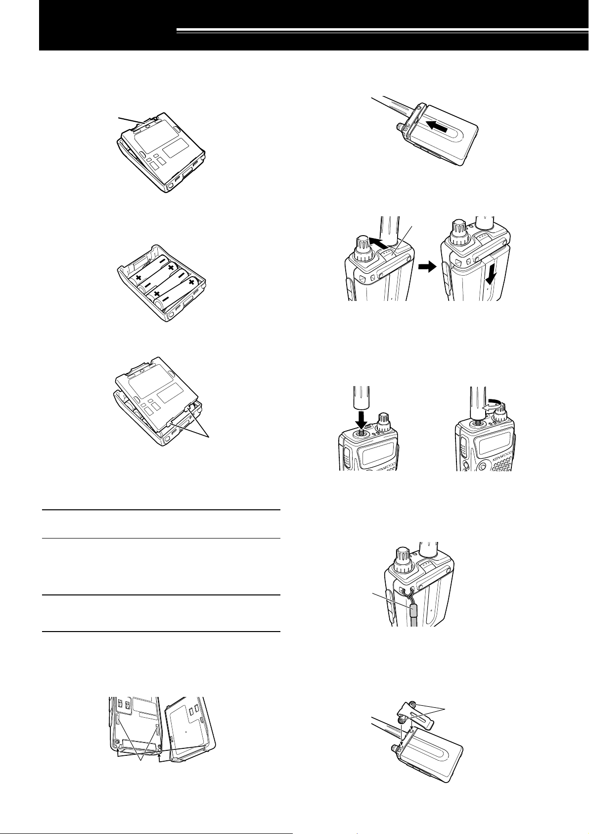
INSTALLING ALKALINE BATTERIES
1 To open the battery case (BT-13), push the locking
tab in, then pull the cover back.
Ta b
2 Insert (or remove) 4 AA (LR6) alkaline batteries.
• Be sure to match the battery polarities with
those marked in the bottom of the battery case.
3 Align the two tabs on the battery case cover, then
close the cover until the locking tabs click.
2 Slide the battery pack along the back of the
transceiver until the release latch on the top of the
transceiver locks the battery pack in place.
3 To remove the battery pack, push the release latch
on top, then slide the battery pack down.
Latch
INSTALLING THE ANTENNA
Hold the base of the supplied antenna, then screw
the antenna into the connector on the top panel of the
transceiver until secure.
Tabs
4 To install the battery case onto (or remove it from)
the transceiver, follow steps 1 to 3 of
“INSTALLING THE Li-ion BATTERY PACK”
{above}.
Note: When you use the alkaline batteries, access Menu No. 30
(BATTERY), then select “ALKALINE”. Otherwise, the battery
remaining cannot be measured correctly {page 34}.
INSTALLING THE OPTIONAL Li-ion
BATTERY PACK (PB-42L)
Note: Because the battery pack is provided uncharged, you must
charge the battery pack before using it with the transceiver. To
charge the battery pack, refer to “CHARGING THE OPTIONAL Liion BATTERY PACK” {page 2}.
1 Position the two grooves on the edge and two
hooks at the bottom of the battery pack over the
corresponding guides on the back of the
transceiver.
a
ATTACHING THE HAND STRAP
If desired, you can attach the supplied hand strap to
the transceiver.
Strap
INSTALLING THE BELT CLIP
You can install the supplied belt clip to the transceiver
tightening the 2 supplied screws.
Screws
Grooves
1
Page 6
1 PREPARATION
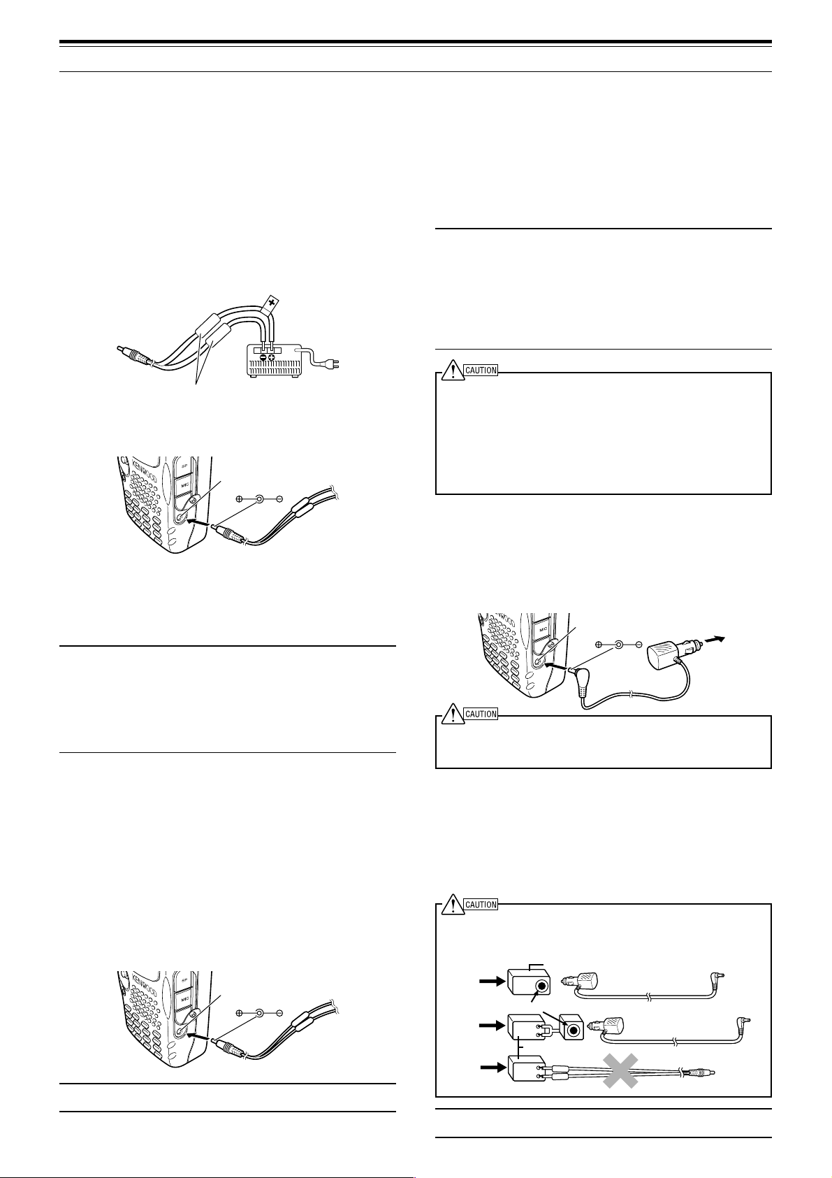
CONNECTING TO A REGULATED POWER
SUPPLY
To connect the transceiver to an appropriate
regulated power supply, use an optional PG-2W
DC cable.
1 Confirm that the power of both the transceiver and
the power supply are OFF.
2 Connect the optional PG-2W DC cable to the
power supply; the red lead to the positive (+)
terminal, and the black lead to the negative (–)
terminal.
Fuses (4 A)
3 Connect the barrel plug on the DC cable to
the DC IN jack of the transceiver.
DC IN jack
3 Plug the charger into an AC wall outlet.
• Charging starts and 2 LEDs on the top panel
lights orange.
4 It takes approximately 6.5 hours to charge an
empty PB-42L Li-ion battery pack. When charging
completes, the LEDs unlight; remove the charger
plug from the transceiver DC IN jack.
5 Unplug the charger from the AC wall outlet.
Note:
◆ If you turn the transceiver ON and press [F], [LOW/ BATT]
while charging the battery pack, “CHARGING” appears.
“STANDBY” appears when the charging completes.
◆ The transceiver becomes warm while charging the battery
pack.
◆ If the charger plug is plugged into the DC IN jack before the
battery pack is attached, turn the transceiver ON and then
OFF again to initiate the charging.
◆ Exceeding the specified charge period shortens the useful life
of the Li-ion battery pack.
◆ The provided charger is designed to charge only the provided
PB-42L Li-ion battery pack. Charging other models
of battery packs may damage the charger and battery pack.
◆ Do not press [PTT] while charging.
◆ The battery pack must be kept in cool and dry place.
◆ Never leave the battery pack in the direct sun light.
If the transceiver is turned OFF while a regulated
power supply is connected with the DC IN jack, it
automatically initiates charging the Li-ion battery pack
(PB-42L).
Note:
◆ The supply voltage must be between 12.0 V and 16.0 V to
prevent damaging the transceiver. If input voltage exceeds
approximately 16.5 V, warning beeps sound and “VOLTAGE
ERROR” appears. Remove the DC IN jack plug immediately.
◆ If the DC power supply voltage is above 14.5 V DC and “H”
(High Power) is selected, “H” icon blinks and the output power
is reduced to “L” level (Low Power) automatically {page 39}.
CHARGING THE OPTIONAL Li-ion
BATTERY PACK (PB-42L)
The Li-ion battery pack can be charged after it has
been installed onto the transceiver. The battery pack
is provided uncharged for safety purposes.
1 Confirm that the transceiver power is OFF.
•While charging the battery pack, leave the
transceiver power OFF.
2 Insert the charger plug into the DC IN jack of the
transceiver.
DC IN jack
Note: If the DC power supply voltage is below 12.0 V DC, you
may not be able to charge the Li-ion battery pack (PB-42L).
2
CONNECTING TO A CIGARETTE LIGHTER
SOCKET
To connect the transceiver to the cigarette lighter
socket in your vehicle, use an optional PG-3J
Cigarette Lighter cable.
DC IN jack
Use only the PG-3J, as it has a built in surge protection circuit.
Using other cables may cause smoke or fire if there is a voltage
surge.
While the PG-3J is connected to the cigarette lighter
plug, the transceiver automatically start charging the
Li-ion battery pack (PB-42L). When you operate the
transceiver, it charges the Li-ion battery pack in back
ground. If the transceiver is turned OFF, the 2 LEDs
light orange while charging. When the charging
completes, they turn OFF.
To connect with an external 24 V power source via a DC-DC
converter, only use the PG-3J. Using the PG-2W or other cables
in this situation may cause smoke or fire.
24V
24V
24V
Note: If the input voltage exceeds approximately 16.5 V, warning
beeps sound and “VOLTAGE ERROR” appears.
DC-DC Converter
12V
Socket
12V
DC-DC Converter
12V
PG-3J
PG-3J
DC 12 V
PG-2W
Page 7
YOUR FIRST QSO
FIRST QSO
Are you ready to give your transceiver a quick try?
Reading this page should get your voice on the air
right away. The instructions below are intended only
for a quick guide. If you encounter problems or there
is something you would like to know more, read the
detailed explanations given later in this manual.
8
6
7
4
1
3
FM DUAL BANDER TH-F7
5
2
r Press [BAND] until you select the amateur radio
band you wish to operate.
t Tu rn the Tuning control to select the receive
frequency.
•You may further turn the VOL control to adjust
the volume level of the signal.
y To transmit, hold the transceiver approximately
5 cm from your mouth.
u Press and hold the PTT switch, then speak in your
normal tone of voice.
i Release the PTT switch to receive.
o Repeat steps y, u and i to continue
communication.
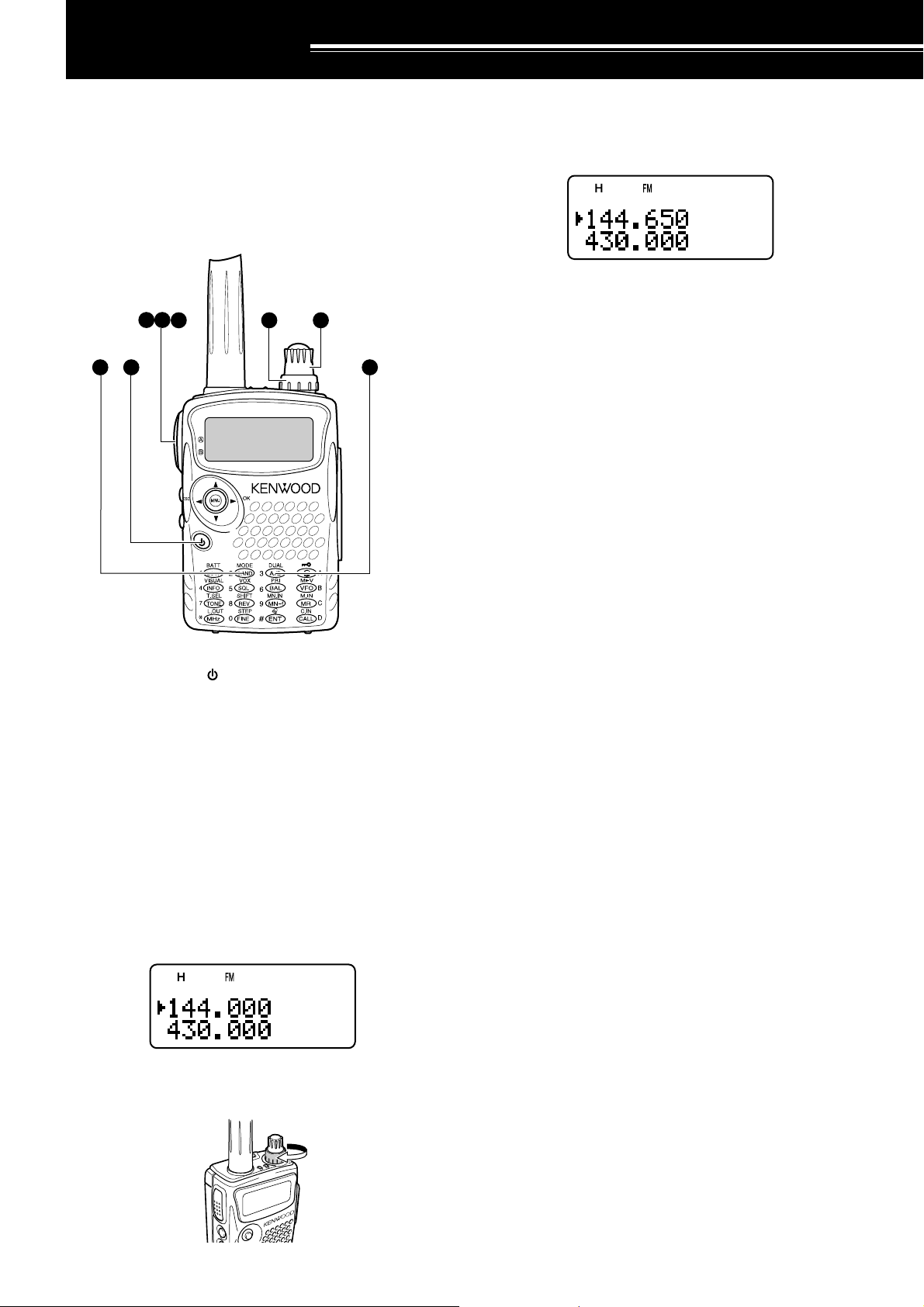
q Press and hold [ ] (POWER) briefly to switch
the transceiver power ON.
•A high pitched double beep sounds and then
“KENWOOD” and “HELLO !!” appear
momentarily. The various indicators and 2
frequencies appear on the LCD.
• The transceiver stores the parameters when it
is turned OFF. It automatically recalls these
parameters next time you turn the transceiver
ON again.
w Press [A/B] to select the frequency band on top.
• Each time you press [A/B], the “s” icon
moves, indicating which frequency band is
currently selected for operation.
e Tu rn the VOL control clockwise to the 11 o’clock
position.
3
Page 8
GETTING ACQUAINTED
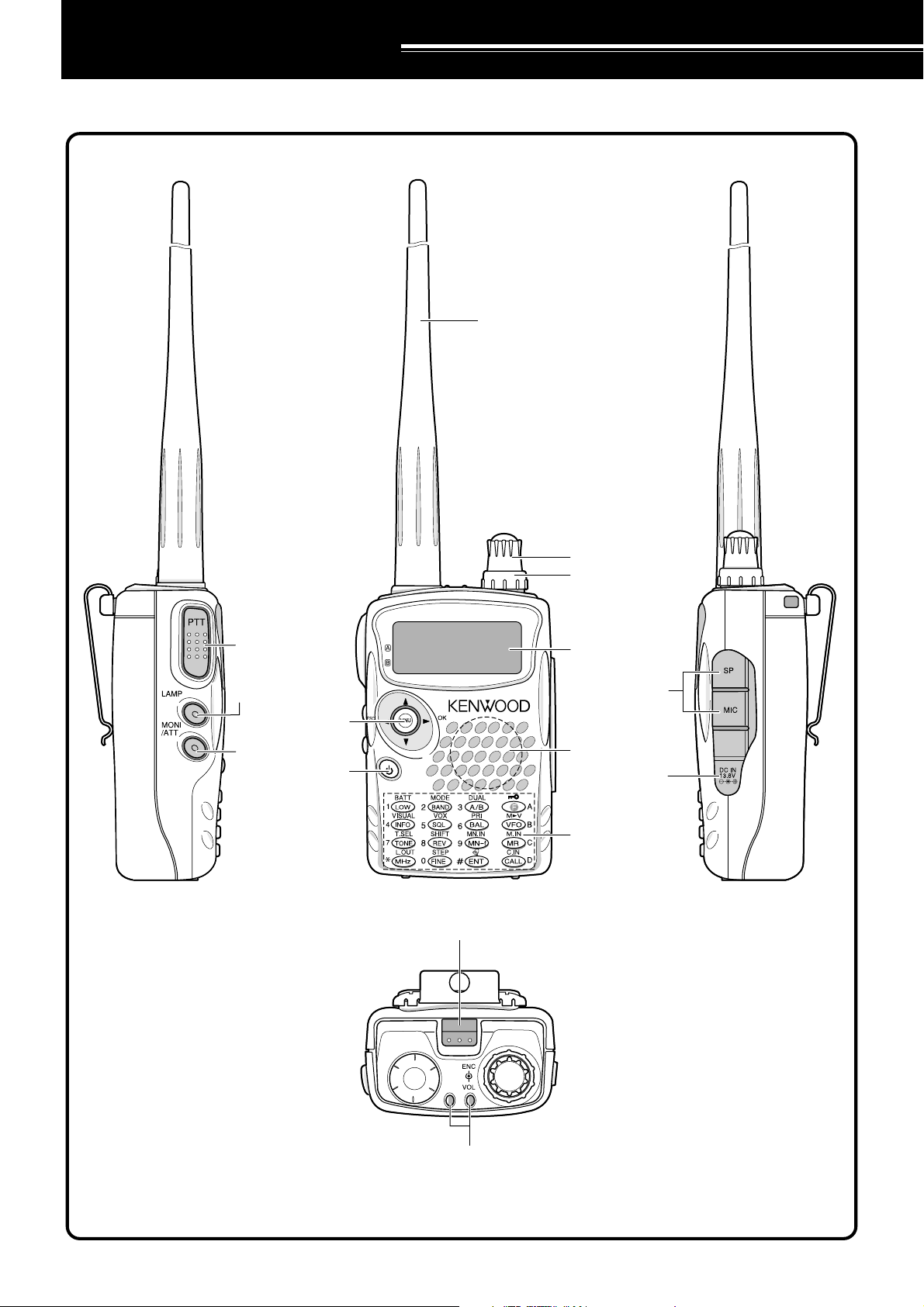
KEYS AND CONTROLS
Antenna
PTT switch
LAMP Key
Multi-scroll
Key
MONI Key
Power Switch
Tuning Control
VOL Control
FM DUAL BANDER TH-F7
Display
SP/MIC jack
Speaker/ Mic.
DC IN jack
Keypad
Battery release
M
A/ B-band status LEDs
Green : Busy
Red : Transmitting
Orange: Charging
4
Page 9
DISPLAY
1
2 3 4 5 6 7 8 9 10 11 12 13
3 GETTING ACQUAINTED
14
22
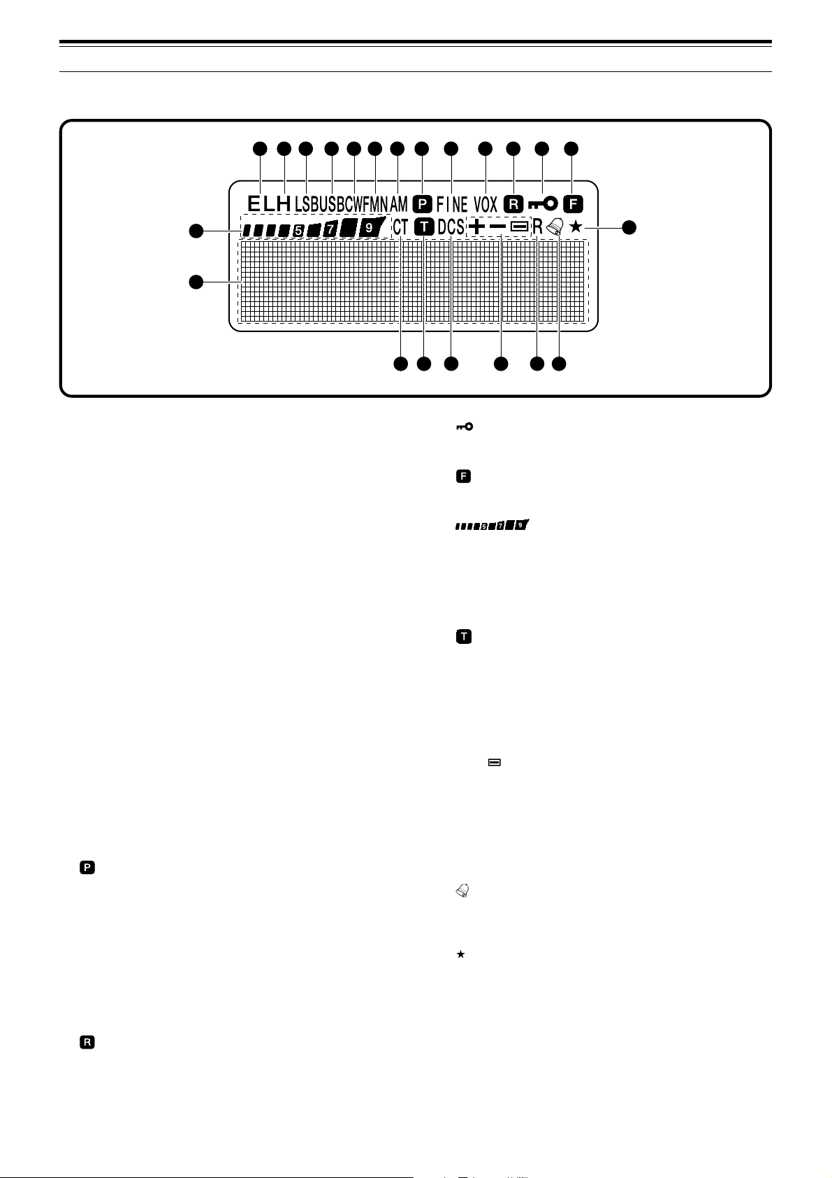
q EL
Appears when the transmit output power is set to Low
(“L”) or Economic Low (“EL”) {pages 7, 39}.
w H
Appears when the transmit output power is set to
High (“H”) {pages 7, 39}.
e LSB
Appears when lower side band (LSB) is selected for
B-band {page 32}.
r USB
Appears when upper side band (USB) is selected for
B-band {page 32}.
t CW
Appears when CW is selected for B-band {page 32}.
y WFMN
“WFM” appears when wide FM mode is selected
{page 32}. “FM” appears when normal FM mode is
selected. “FMN” appears when narrow FM mode is
selected {page 37}.
u AM
“AM” appears when AM mode is selected {page 32}.
i
Appears when a Priority Scan is activated {page 24}.
o FINE
Appears when a Fine Tuning function is activated
{page 33}.
!0 VOX
Appears when the VOX function is activated
{page 39}.
!1
Appears when the Automatic Simplex Check (ASC) is
activated {page 14}.
15
21
16
17
18
19
20
!2
Appears when the Lock function is ON {page 36}.
!3
Appears when the function key is pressed.
!4
S-meter (RX) and relative RF power meter (TX).
!5 CT
“CT” appears when the CTCSS function is activated
{page 27}.
!6
Appears when the Tone function is activated
{page 13}.
!7 DCS
Appears when the DCS function is activated
{page 29}.
!8 +/ –/
Appears when the repeater shift function is activated
{page 12}.
!9 R
Appears when the Reverse function is activated
{page 14}.
@0
Appears when the Tone Alert function is activated
{page 38}.
@1
Appears when the displayed memory channel has
been locked out {page 26}.
@2 Dot-matrix display
76 x 16 dot-matrix display. It displays various
information, such as the operating frequencies, menu
settings, and etc.
5
Page 10
3 GETTING ACQUAINTED
BASIC OPERATION
SWITCHING POWER ON/ OFF
1 Press [ ] (POWER) briefly to switch the
transceiver power ON.
• Upon power up, a high pitched double beep
sounds, followed by the frequencies and other
indicators.
2 To switch the transceiver OFF, press [ ]
(POWER) again.
•When you turn the transceiver OFF, a low
pitched double beep sounds.
• The transceiver stores the parameters when it
is turned OFF. It recalls these parameters next
time you turn the transceiver ON again.
ADJUSTING VOLUME
Tu rn the VOL control clockwise to increase the audio
output level and counterclockwise to decrease the
output level.
• The higher the level, the stronger the signals
must be, to receive.
•6 different levels can be set
(-- -- -- -- --: level 0 ~ || || || || ||: level 5).
3 Press [ ] or [MNU] to store the new settings or
press [ ] to cancel without changing the current
setting.
Note: When operating in USB, LSB and CW modes, the squelch
unmutes up to level 2.
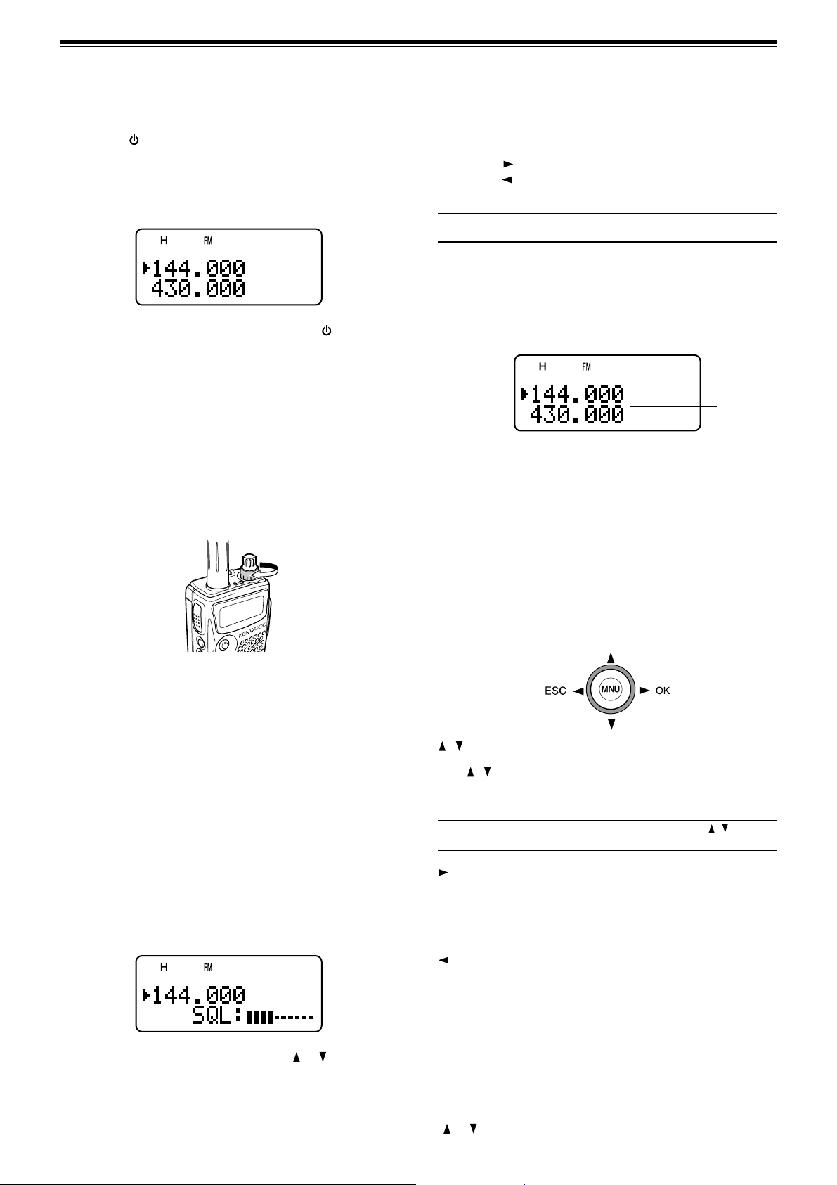
SELECTING A BAND
By default, two frequencies are displayed on the
LCD. The frequency on top is called the A-band. The
bottom frequency is called the B-band.
A-band
B-band
Press [A/B] to select the A-band or B-band for
operation. Each time you press [A/B], the “s” icon
moves, indicating which band is currently selected for
operation. Usually, select the A-band to operate the
amateur band and select the B-band to receive the
various broadcasting stations, such as AM, FM, TV
(audio only) or another amateur band {page 33}.
• If you are not receiving a signal, press and hold
[MONI] to unmute the speaker, then adjust the
VOL control to a comfortable audio output level.
ADJUSTING SQUELCH
The purpose of the Squelch is to mute the speaker
when no signals are present. With the squelch level
correctly set, you will hear sound only while actually
receiving signals. The higher the selected squelch
level, the stronger the signals must be, to receive.
The appropriate squelch level depends on the
ambient RF noise conditions. You can configure
independent threshold squelch levels for the A-band
and B-band.
1 Press [SQL].
• The current squelch level appears.
MULTI-SCROLL KEY
This transceiver has a 4-way cursor key with a MENU
(“MNU”) key in the center.
/ keys
The / keys function in the same way as the
Tuning control. These keys change the frequencies,
memory channels, and other selections.
Note: You can use the Tuning control in place of the / keys
for most of the controls.
/ OK key
Press to move to the next step or complete the
setting in various modes, such as Menu mode,
CTCSS frequency selection, and DCS code selection.
/ ESC key
Press to move back or cancel the entry in various
modes, such as Menu mode, CTCSS frequency
selection, and direct frequency entry.
2 Tu rn the Tuning control or press [ ]/ [ ] to adjust
the level.
• Select the level at which the background noise
is just eliminated when no signal is present.
6
MNU key
Press to enter the Menu mode.
In Menu mode, you can select the desired menu
number by turning the Tuning control or pressing
[ ]/ [ ]. It also functions as [OK] key.
Page 11
3 GETTING ACQUAINTED
TRANSMITTING
1 To transmit, hold the transceiver approximately
5 cm (2 inches) from your mouth, then press and
hold the PTT switch and speak into the
microphone in your normal tone of voice.
• The status LED on the top panel lights red and
bar-graph meter appears.
• If you press [PTT] while you are outside of the
transmission coverage, a high pitched error
beep sounds.
2 When you finish speaking, release the PTT switch.
Note: If you transmit continuously for more than 10 minutes, the
internal time-out timer generates a warning beep and the
transceiver stops transmitting. In this case, release the PTT
switch and let the transceiver cool down for a while, then press
the PTT switch again to resume transmitting {pages 38, 48}.
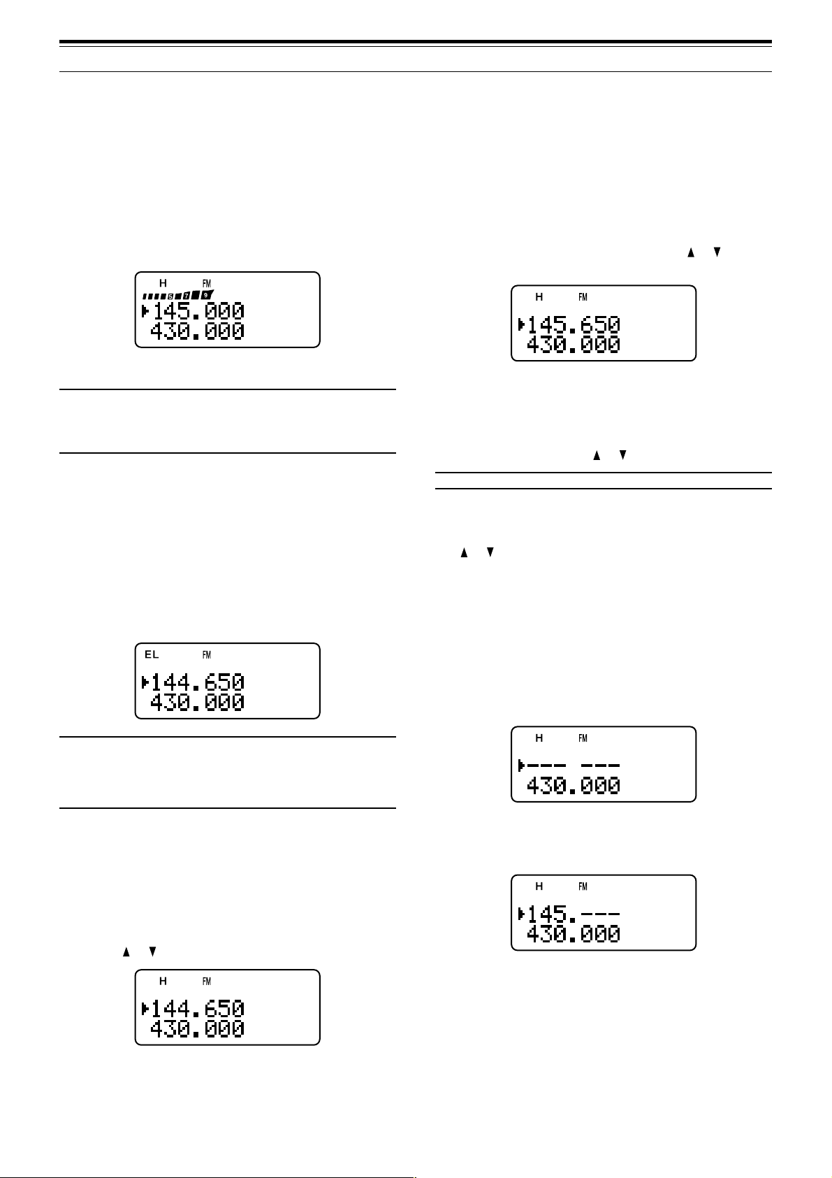
■ Selecting Output Power
Selecting lower transmission power is the best
way to reduce the battery consumption, if
communication is still reliable. You can configure
different power levels for transmission {page 39}.
Press [LOW].
• Each time you press [LOW], the indicator
cycles between “H” (high), “L” (low), and “EL”
(economic low).
■ MHz Mode
If the desired operating frequency is far away from
the current frequency, it is quicker to use the MHz
tuning mode.
To adjust the MHz digit:
1 Press [MHz].
•A MHz digit blinks.
2 Tu rn the Tuning control or press [ ]/ [ ] to
select the desired MHz digit.
3 After selecting the desired MHz digit, press
[MHz] to exit the mode and return to normal
VFO mode {above}.
4 You may further adjust the frequency using the
Tuning control or [ ]/ [ ].
Note: MHz mode does not function in AM band.
■ Direct Frequency Entry
In addition to turn the Tuning control or press
[ ]/ [ ], there is another way of selecting the
frequency. When the desired frequency is far
away from the current frequency, you can directly
enter a frequency from the numeric keypad.
1 Press [VFO].
•You must be in the VFO mode to make the
direct frequency entry.
2 Press [ENT].
• “– – – – – –” appears.
Note:
◆ You can store different output power setting for the A and Bband.
◆ When you change the output power, it is reflected to all
available amateur bands for A or B-band.
SELECTING A FREQUENCY
■ VFO Mode
This is the basic mode for changing the operating
frequency. Turn the Tuning control clockwise to
increase the frequency. Turn the Tuning control
counterclockwise to decrease the frequency. Or,
press [ ]/ [ ] to change the frequency.
3 Press the numeric keys ([0] to [9]) to enter
your desired frequency. [MHz] can be used to
complete the MHz digits entry.
• Pressing [ENT] fills the remaining digits (the
digits you did not enter) with 0 and
completes the entry.
•To select 145.000 MHz for example, press
[1], [4], [5] then press [ENT] to complete
the entry.
• If you want to revise the MHz digits only,
press [VFO] in place of [ENT].
7
Page 12

3 GETTING ACQUAINTED
Example 1 (100 MHz < f < 1000 MHz)
To enter 438.320 MHz:
Key in Display
[ENT] – –– –––
[4], [3], [8] 4 3 8. – – –
[3], [2], [0] 4 3 8. 3 2 0
Note: You do not have to press [MHz] when you are entering
3-digit MHz number.
Example 2
To enter 439.000 MHz:
Key in Display
[ENT] ––– –––
[4], [3], [9] 4 3 9. – – –
[ENT] 4 3 9. 0 0 0
Example 3
To revise 144.650 MHz to 145.650 MHz:
Example 6
To enter 810 kHz (B-band only):
Key in Display
[ENT] ––– –––
[0] 0 – – – – –
[MHz] 0. – – –
[8], [1], [0] 0. 8 1 0
Note:
◆ If the entered frequency does not match the current frequency
step size, the frequency is automatically rounded down to the
next available frequency.
◆ When the desired frequency cannot be entered exactly, check
whether the Fine Tuning function is ON or not
{page 33}, and then confirm the frequency step size
{page 35}.
◆ Some frequency ranges are blocked, due to government
regulations. Refer to the specifications {pages 50, 51} for the
TX/ RX coverage.
◆ If you turn the Tuning control or press [ ]/ [ ] while entering
the frequency, the transceiver clears the entry and recovers
the previous frequency and mode.
Key in Display
1 4 4. 6 5 0
[ENT] ––– –––
[1], [4], [5] 1 4 5. – – –
[VFO] 1 4 5. 6 5 0
Example 4 (f > 1000 MHz)
To enter 1250.500 MHz (B-band only):
Key in Display
[ENT] ––– –––
[1], [2], [5], [0] 12 5 0. – – –
[5] 12 5 0. 5 – –
[ENT] 12 5 0. 5 0 0
Example 5 (f < 100 MHz)
To enter 10.500 MHz (B-band only):
Key in Display
[ENT] ––– –––
[1], [0] 1 0 – – – –
[MHz] 1 0. – – –
[5] 1 0. 5 – –
[ENT] 1 0. 5 0 0 0
Note: When pressing the last [ENT], the Fine Tuning function
is automatically activated for 10.5000 MHz.
8
Page 13
MENU SETUP
WHAT IS A MENU?
Many functions on this transceiver are selected or
configured via a software-controlled Menu, rather
than through the physical controls of the transceiver.
Once familiar with the Menu system, you will
appreciate the versatility it offers. You can customize
the various timings, settings, and programming
functions on this transceiver to meet your needs
without using many controls and switches.
MENU ACCESS
1 Press [MNU].
• The Menu No. and setting appear on the
display, along with a brief explanation of the
Menu No.
2 Tu rn the Tuning control or press [ ]/ [ ] to select
your desired Menu No.
• As you change the Menu No., a brief
explanation of each Menu No. appears.
3 Press [ ] or [MNU] to configure the parameter of
the currently selected Menu No.
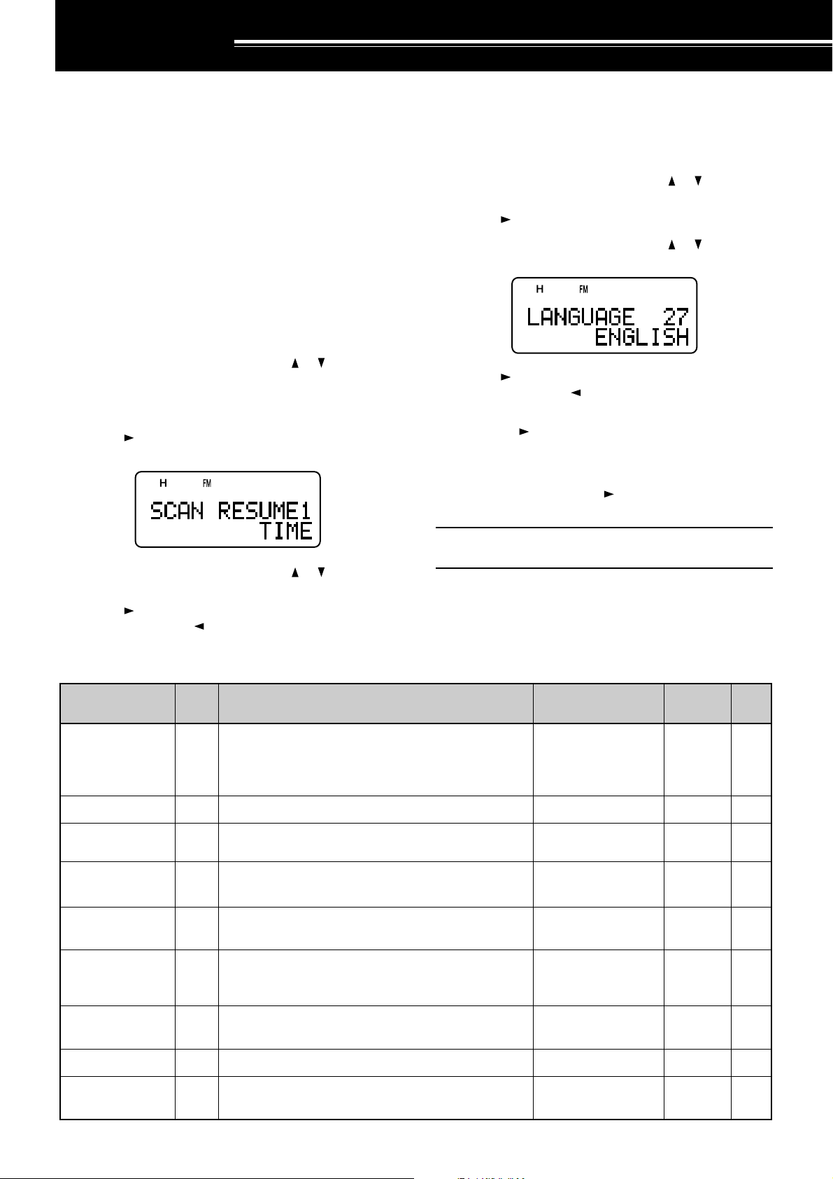
SELECTING A MENU LANGUAGE
You can select either English or Japanese (Katakana)
for the menu description. To switch the language:
1 Press [MNU].
2 Tu rn the Tuning control or press [
Menu No. 27.
3 Press [ ] or [MNU].
4 Tu rn the Tuning control or press [ ]/ [ ] to select
either “ENGLISH” or “JAPANESE”.
5 Press [ ] or [MNU] to store the setting.
Otherwise, press [ ] or [PTT] to cancel.
•When you select “JAPANESE” in step 3 and
press [ ] or [MNU], all Menu explanations are
displayed in Japanese (Katakana). To return to
English mode, repeat step 1, 2 and 3 {above}
to access Menu No. 27, then select
“ENGLISH”. Press [ ] or [MNU] to display the
Menu mode in English.
]/ [ ] to select
4 Tu rn the Tuning control or press [ ]/ [ ] to select
your desired parameter.
5 Press [ ] or [MNU] to store the setting.
Otherwise, press [ ] or [PTT] to cancel.
MENU FUNCTION LIST
yalpsiDehtnO
EMUSERNACS1
KNILPRG.M2 noitarugifnockniLpuorGyromeM76543210skniLoN32
DOHTEMRM3 noitidnocllaceRyromeM
OFVGORP4
TESFFOOTUA5 noitcnuftesffOretaepeRotuAFFO/NONO31
uneM
.oN
dohtememusernacS
)ylnodnab-A(
Note: The menu language selection does not affect any other
modes, such as memory name {page 17} or DTMF name {page
31}.
noitcnuF snoitceleS tluafeD
edomdetarepO-emiT:EMIT
edomdetarepO-reirraC:REIRRAC
edompotsdnakeeS:KEES
egnarycneuqerfOFVelbammargorP
—
/REIRRAC/EMIT
KEES
/SDNABLLA
DNABTNERRUC
EMIT62
LLA
SDNAB
eeS
ecnerefeR
egaP
.feR
gaPe
61
73
zHM59.95~00.0
TESFFO6 ycneuqerftesfforetaepeR
ELBANEENUT7
TIBIHNIXT8 noissimsnartehttibihnIFFO/NOFFO83
KCAJCIM/PS9ehttceleS CIM/PS noitcnufkcajCP/CNT/CIM/PSCIM/PS
dekcolera
ehtfoesutimreP gninuT syekehtnehwlortnoc
fospetsni
zHM50.0
FFO/NOFFO63
eeS
egaP
ecnerefeR
21
24
34
9
Page 14

4 MENU SETUP
yalpsiDehtnO
uneM
.oN
noitcnuF snoitceleS tluafeD
EROTSFMTD01seiromemFMTDnisrebmunFMTDerotS—ataDoN03
DPSFMTD11deepsnoissimsnartenotFMTDWOLS/TSAFTSAF13
DLOHFMTD21
ESUAPFMTD31
seirtneyekFMTD
senot
neewtebsdnoces2rofnoissimsnartehtdloH
FMTDgnittimsnartelihwnoitarudesuapehT
FFO/NOFFO03
/005/052/001
/0051/0001/057
sm00513
sm0002
KCOLFMTD41syekhtiwnoissimsnartFMTDelbasiDFFO/NOFFO13
GSMNO-RWP51egassemno-rewoPsretcarahc8
TSARTNOC61
tsartnocyalpsidDCL
mumixam:61~muminim:1
61~1853
!!OLLEH
/6.0/4.0/2.0/FFO
REVASTAB71doirepffo-tuhsreviecerrevasyrettaB
/0.3/0.2/0.1/8.0
.ces0.153
.ces0.5/0.4
.feR
gaPe
73
OPA81noitcnufffOrewoPcitamotuA.nim06/03/FFO.nim0343
PEEBYEK91noitcnufpeeBFFO/NONO53
YSUBnoXOV02
NIAGXOV12
ysub
ytivitisnesniagXOVehtteS
evitisnestsom:9~evisitnestsael:0
sireviecerehtnehwnoissimsnartXOVwollA
FFO/NOFFO04
9~0493
/057/005/052
YALEDXOV22emityaledXOVehttsujdA
/0002/0051/0001
sm00504
sm0003
YEKLLAC32yekLLACehtrofnoitcnufatceleSzH0571/LLACLLAC91
DLOH057142
dettimsnart
sienotzH0571anehwsutatsXTehtdloH
FFO/NOFFO31
TFIHSTAEB52ycneuqerfkcolcUPClanretniehttfihSFFO/NOFFO53
TNARAB62zHM1.01wolebannetnarablanretninaelbanE
EGAUGNAL72egaugnalunemehttceleS
/DELBANE
DELBASID
/HSILGNE
ESENAPAJ
DELBANE
HSILGNE
33
9
10
TEKCAP82deepstekcapCNTlanretxenatceleSspb0069/0021spb002124
WORRANMF92noitarepodnabworranMFFFO/NOFFO73
YRETTAB03epytyrettabatceleS
/MUIHTIL
ENILAKLA
MUIHTIL
/TESEROFV/ON
?TESER13edomteseratceleS
/TESERUNEM
ON74
TESERLLUF
43
Page 15

4 MENU SETUP
ALPHABETICAL FUNCTION LIST
yalpsiDehtnO .oNuneM snoitceleS tluafeD gaP.feRe
OPA81setunim06/03/FFO.nim0343
TESFFOOTUA5 FFO/NONO31
TNARAB62DELBASID/DELBANEDELBANE33
YRETTAB03ENILAKLA/MUIHTILMUIHTIL43
REVASTAB71.ces0.5/0.4/0.3/0.2/0.1/8.0/6.0/4.0/2.0/FFO.ces0.153
TFIHSTAEB52FFO/NOFFO53
YEKLLAC32zH0571/LLACLLAC91
TSARTNOC6161~1853
DLOHFMTD21FFO/NOFFO03
KCOLFMTD41FFO/NOFFO13
ESUAPFMTD31sm0002/0051/0001/057/005/052/001sm00513
DPSFMTD11WOLS/TSAFTSAF13
EROTSFMTD01— ataDoN03
WORRANMF92FFO/NOFFO73
PEEBYEK91FFO/NONO53
EGAUGNAL72ESENAPAJ/HSILGNEHSILGNE9
DOHTEMRM3 DNABTNERRUC/SDNABLLA
KNILPRG.M2 76543210skniLoN32
TESFFO6 zHM50.0fospetsnizHM59.95~00.0
TEKCAP82spb0069/0021spb002124
OFVGORP4 — —73
GSMNO-RWP51sretcarahc8!!OLLEH73
?TESER13TESERLLUF/TESERUNEM/TESEROFV/ONON74
EMUSERNACS1 KEES/REIRRAC/EMITEMIT62
LLA
SDNAB
eeS
ecnerefeR
egaP
61
21
KCAJCIM/PS9 CP/CNT/CIM/PSCIM/PS34,24
ELBANEENUT7 FFO/NOFFO63
TIBIHNIXT8 FFO/NOFFO83
YALEDXOV22sm0003/0002/0051/0001/057/005/052sm00504
NIAGXOV129~0493
YSUBnoXOV02FFO/NOFFO04
DLOH057142FFO/NOFFO31
11
Page 16
OPERATING THROUGH REPEATERS
Repeaters, which are often installed and maintained
by radio clubs, are usually located on mountain tops
or other elevated locations. Generally they operate at
higher ERP (Effective Radiated Power) than a typical
station. This combination of elevation and high ERP
allows communications over much greater distances
than communications without using repeaters.
Most repeaters use a receive and transmit frequency
pair with a standard or non-standard offset (odd-split).
In addition, some repeaters must receive a tone from
the transceiver to allow it to access. For details,
consult your local repeater reference.
TX: 144.725 MHz
TX tone: 88.5 Hz
RX: 145.325 MHz
TX: 144.725 MHz
TX tone: 88.5 Hz
RX: 145.325 MHz
PROGRAMMING OFFSET
First select an amateur radio repeater downlink
frequency on the A-band or B-band as described in
“SELECTING A FREQUENCY” {page 7}.
■ Selecting Offset Direction
Select whether the transmit frequency will be
higher (+) or lower (–) than the receive frequency.
Press [F], [REV] to select the offset direction.
• “+” or “–” appears, indicating which offset
direction is selected.
•To program –7.6 MHz offset on the TH-F7A
(430 MHz only), repeatedly press [F], [REV]
until “ ” appears.
If the offset transmit frequency falls outside the
allowable range, transmitting is inhibited. In this
case, adjust the receive frequency so that the
transmit frequency is within the band limits.
Note: While using an odd-split memory channel or
transmitting, you cannot change the offset direction.
OFFSET PROGRAMMING FLOW
q
Select a band.
w
Select a receive frequency.
Select an offset direction.
e
r
Select an offset frequency
(only when programming odd-split
repeater frequencies).
t
Activate the Tone function
(if necessary).
y
Select a tone frequency
(if necessary).
If you store the above data in a memory channel, you
need not reprogram every time. See “MEMORY
CHANNELS” {page 15}.
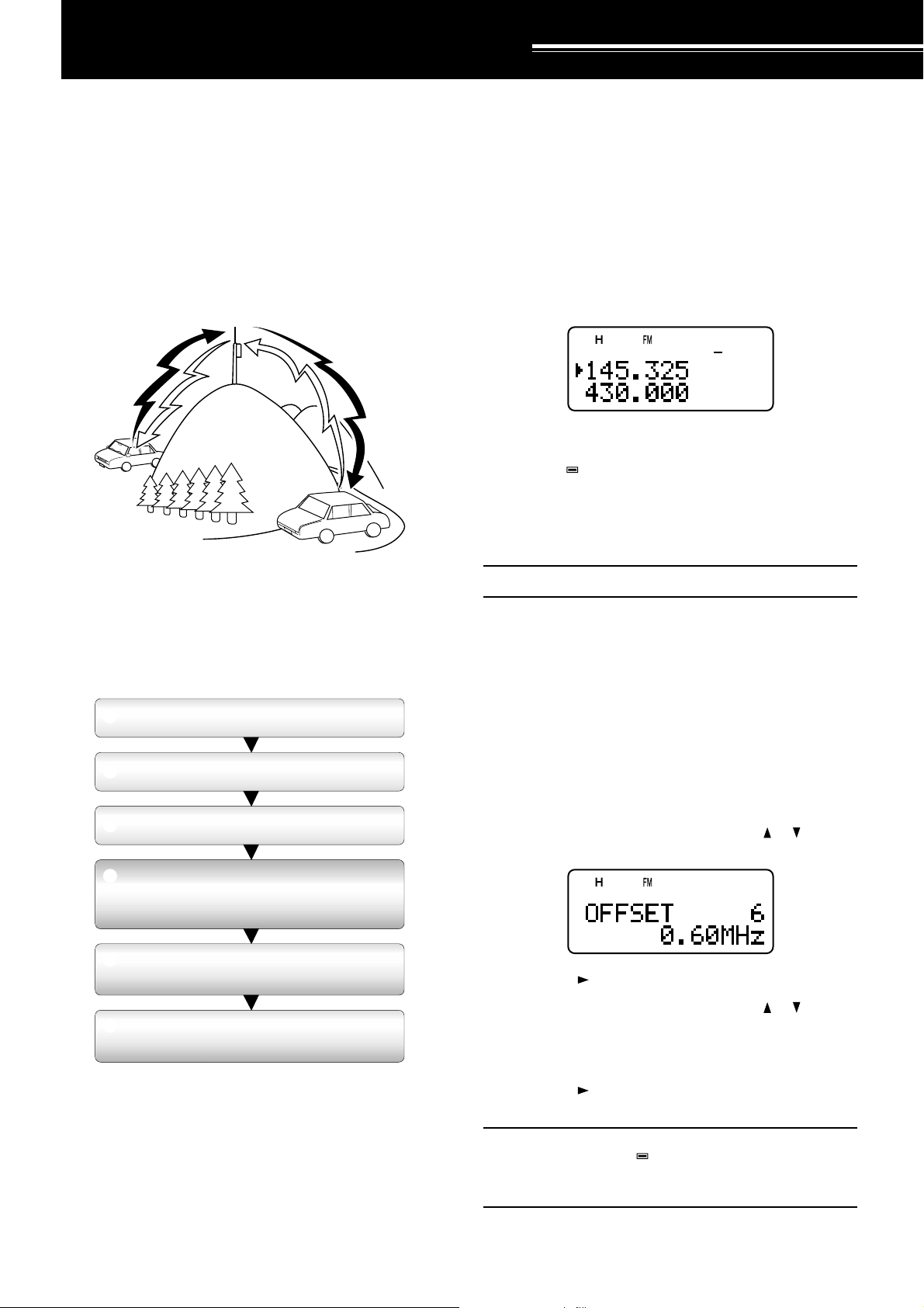
■ Selecting Offset Frequency
To access a repeater which requires an odd-split
frequency pair, change the offset frequency from
the default which is used by most repeaters. The
default offset frequency on the 2 m band is
600 kHz; the default on the 70 cm band is 1.6
MHz.
1 Press [BAND] to select an amateur radio band
you want to change the offset frequency.
2 Press [MNU].
3 Tu rn the Tuning control or press [ ]/ [ ] to
select Menu No. 6 (OFFSET).
4 Press [ ] or [MNU].
5 Tu rn the Tuning control or press [ ]/ [ ] to
select the appropriate offset frequency.
• The selectable range is from 0.00 MHz to
59.95 MHz in steps of 50 kHz.
6 Press [ ] or [MNU] to store the setting.
Otherwise, press [PTT] to cancel.
Note:
◆ If you have selected “ ” for the offset direction, you cannot
change the default (–7.6 MHz) offset frequency.
◆ After changing the offset frequency, the new offset frequency
will also be used by Automatic Repeater Offset.
12
Page 17
5 OPERATING THROUGH REPEATERS
S
S
S: Simplex
–
144.0
146.0 MHz145.8145.6
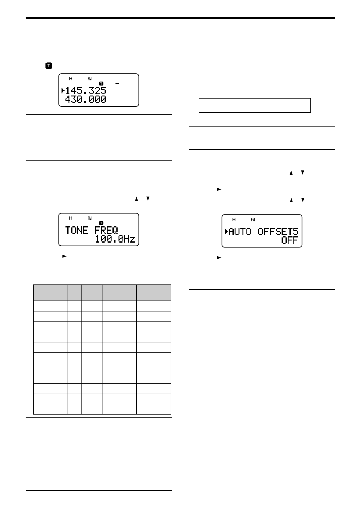
■ Activating Tone Function
Press [TONE] to switch the Tone function ON (or
OFF).
•“
Note:
◆ You cannot use the Tone and CTCSS/ DCS functions at the
◆ When you access repeaters that require 1750 Hz tones, you
” appears when the Tone function is ON.
same time. Switching the Tone function ON after activating
the CTCSS/ DCS deactivates the CTCSS/ DCS function.
need not activate the Tone function. Press [CALL] without
pressing the PTT switch to transmit a 1750 Hz tone (default
setting).
■ Selecting a Tone Frequency
1 While the Tone function is ON, press [F],
[TONE].
2 Tu rn the Tuning control or press [ ]/ [ ] to
select the desired tone frequency.
AUTOMATIC REPEATER OFFSET
This function automatically selects an offset direction,
according to the frequency that you select on the
2 m band. The transceiver is programmed for offset
direction as shown below. To obtain an up-to-date
band plan for repeater offset direction, contact your
national Amateur Radio association.
Note: Automatic Repeater Offset does not function when
Reverse is ON. However, pressing [REV] after Automatic
Repeater Offset has selected an offset (split) status, exchanges
the receive and transmit frequencies.
1 Press [MNU].
2 Tu rn the Tuning control or press [ ]/ [ ] to select
Menu No. 5 (AUTO OFFSET).
3 Press [ ] or [MNU].
4 Tu rn the Tuning control or press [ ]/ [ ] switch
the function ON or OFF.
3 Press [ ] or [MNU] to complete the setting.
Otherwise, press [PTT] to cancel.
Available Tone Frequencies
.oN
.qerF
.oN
)zH(
.qerF
.oN
)zH(
.qerF
.oN
)zH(
100.76214.79323.141435.602
203.96310.001422.641537.012
309.17415.301524.151631.812
404.47512.701627.651737.522
500.77619.011722.261831.922
607.97718.411829.761936.332
705.28818.811928.371048.142
804.58910.321039.971143.052
905.88023.721132.681241.452
015.19128.131238.291
118.49225.631335.302
Note:
◆ 42 different tones are available for the transceiver. These 42
tones includes 37 EIA standard tones and 5 non-standard
tones.
◆ To transmit a 1750 Hz tone, simply press [CALL] without
pressing the PTT switch (default setting). Release [CALL] to
quit transmitting. You can also make the transceiver remain in
the transmit mode for 2 seconds after releasing [CALL]; a
1750 Hz tone is not continuously transmitted. Access Menu
No. 24 (1750 HOLD) and select “ON”.
◆ If you desire to assign [CALL] for recalling the Call channel in
place of transmitting the 1750 Hz tone, access Menu
No. 23 (CALL KEY) and select “CALL”.
5 Press [ ] or [MNU] to store the setting.
Otherwise, press [PTT] to cancel.
Note: If you select the frequency within the amateur radio band
on the B-band, the Automatic Repeater Offset function is also
.qerF
activated in any modes.
)zH(
13
Page 18
5 OPERATING THROUGH REPEATERS
REVERSE FUNCTION
The reverse function exchanges a separate receive
and transmit frequency. So, while using a repeater,
you can manually check the strength of a signal that
you receive directly from the other station. If the
station’s signal is strong, both stations should move
to a simplex frequency and free up the repeater.
145.325 MHz
144.725 MHz
144.725 MHz
TX: 144.725 MHz TX: 144.725 MHz TX: 144.725 MHz TX: 145.325 MHz
RX: 145.325 MHz RX: 145.325 MHz RX: 145.325 MHz RX: 144.725 MHz
To swap the transmit and receive frequencies:
Press [REV] to switch the Reverse function ON (or
OFF).
• “R” appears when the function is ON.
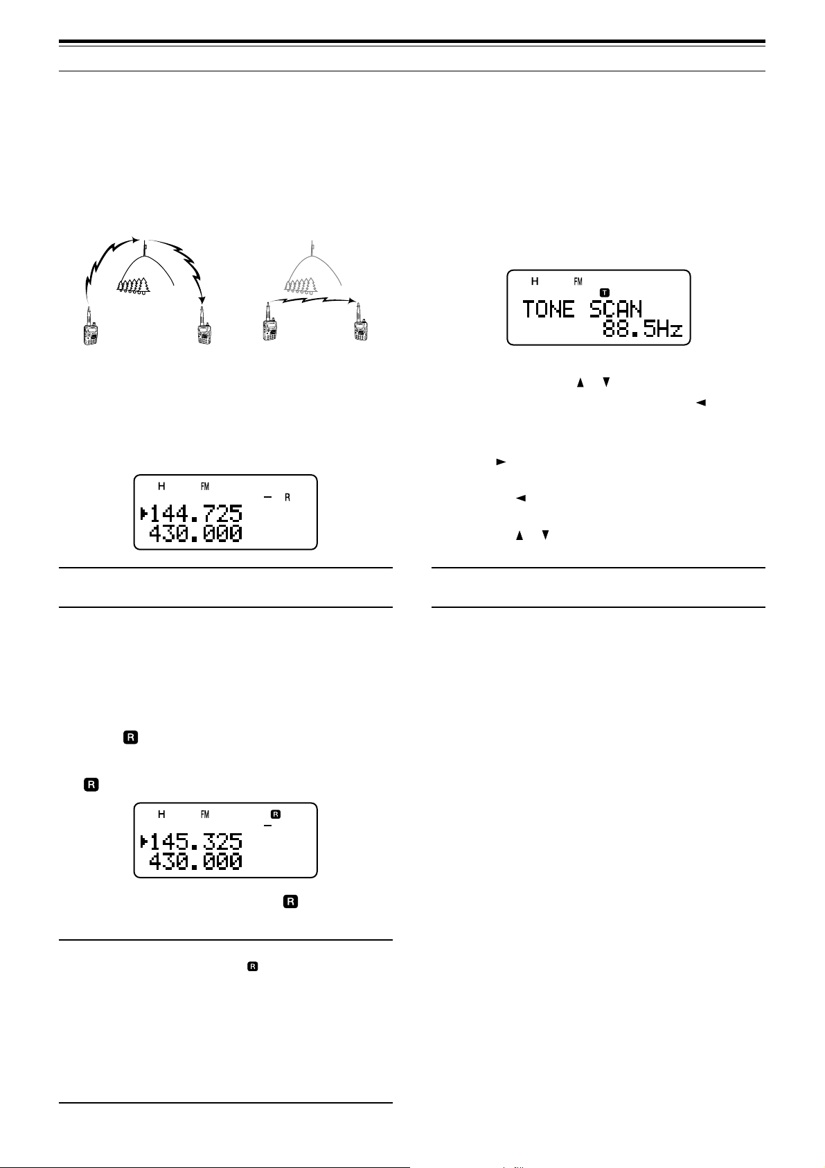
TONE FREQ. ID SCAN
This function scans through all tone frequencies to
identify the incoming tone frequency on a received
signal. You may use the function to find which tone
frequency is required by accessing your local
repeater.
1 While the Tone function is ON, press [F],
[TONE] (1 s) to start the Tone Freq. ID scan.
•When the transceiver receives the signal, the
scan starts.
•To reverse the scan direction, turn the Tuning
control or press [ ]/ [ ].
•To quit the function, press [PTT] or [ ].
• When the tone frequency is identified, a beep
sounds and the identified frequency appears.
2 Press [ ] to program the identified frequency in
place of the current tone frequency.
• Press [ ] if you do not want to program the
identified frequency.
• Press [ ]/ [ ] while the identified frequency is
blinking, to resume scanning.
Note: You can turn the Reverse function ON when you are
operating in Simplex mode. However, it does not change the TX/
RX frequency.
AUTOMATIC SIMPLEX CHECK (ASC)
While using a repeater, the ASC function periodically
checks the strength of a signal that you are receiving
directly from the other station. If the station’s signal is
strong enough to allow direct contact without a
repeater, “ ” indicator on the display starts blinking.
Press [REV] (1 s) to switch the function ON.
•“ ” appears when the function is ON.
•While direct contact is possible, “ ” blinks.
•To quit the function, press [REV].
Note:
◆ Pressing the PTT switch causes “ ” icon to quit blinking.
◆ ASC can be activated while operating in Simplex mode.
However, it does not change the TX/ RX frequencies.
◆ ASC does not function while scanning.
◆ Activating ASC while using Reverse switches Reverse OFF.
◆ If you recall a memory channel or the Call channel that
contains a Reverse ON status, ASC is switched OFF.
◆ ASC causes received audio to be momentarily intermitted
every 3 seconds.
◆ ASC does not function when the band is not selected for
operation.
Note: Some repeaters do not re-transmit the access tone in the
downlink signal. In this case, check the other station’s uplink
signal to detect the repeater access tone.
14
Page 19

MEMORY CHANNELS
In memory channels, you can store frequencies and
related data that you often use. Then you need not
reprogram those data every time. You can quickly
recall a programmed channel through simple
operation. A total of 400 memory channels are
available for storing the frequencies, modes and
other operating conditions of the A and B-bands.
SIMPLEX & REPEATER OR
ODD-SPLIT MEMORY CHANNEL?
You can use each memory channel as a simplex &
repeater channel or an odd-split channel. Store only
one frequency to use as a simplex & repeater
channel or two separate frequencies to use as an
odd-split channel. Select either application for each
channel depending on the operations you have in
mind.
Simplex & repeater channels allow:
• Simplex frequency operation
• Repeater operation with a standard offset
(if an offset direction is stored)
Odd-split channels allow:
• Repeater operation with a non-standard offset
STORING SIMPLEX FREQUENCIES OR
STANDARD REPEATER FREQUENCIES
1 Press [VFO].
2 Tu rn the Tuning control or press [
your desired frequency in the amateur radio
bands.
•You can also directly enter desired frequency
using the keypad {page 7}.
3 If storing a standard repeater frequency, select the
following data:
• Offset direction {page 12}
•Tone function, if necessary {page 13}
• CTCSS/ DCS function, if necessary
{pages 28, 29}
If storing a simplex frequency, you may select
other related data (CTCSS or DCS settings, etc.).
4 Press [F].
]/ [ ] to select
Note: Not only can you store data in memory channels, but you
can also overwrite existing data with new data.
The data listed below can be stored in each memory
channel:
retemaraP
ycneuqerfevieceR
ycneuqerftimsnarTseY
ycneuqerfenoTseYseY
NOenoTseYseY
ycneuqerfSSCTCseYseY
NOSSCTCseYseY
edocSCDseYseY
NOSCDseYseY
noitceridtesffOseYA/N
ycneuqerftesffOseYA/N
NOesreveRseYA/N
ezispetsycneuqerFseYseY
tuokcollennahcyromeMseYseY
emanlennahcyromeMseYseY
NOgninutENIFseYseY
noitcelesedoMseYseY
Yes: Can be stored in memory.
N/A: Cannot be stored in memory.
Note: The transmit frequency must be on the same band as the
receive frequency band (Odd-split channel).
&xelpmiS
retaepeR
seY
seY
•A memory channel number appears and blinks.
•“” indicates the current channel is empty; “ ”
appears if the channel contains data.
• Memory channel number L0/U0 ~ L9/U9
{page 23}, I–0 ~ I–9 {page 20}, and Pr1 and
tilpS-ddO
Pr2 {page 25} are reserved for other functions.
5 Tu rn the Tuning control or press [ ]/ [ ] to select
the memory channel in which you want to store
the data.
6 Press [MR] ([ ] or [MNU]) to store the data to the
channel.
STORING ODD-SPLIT REPEATER FREQUENCIES
Some repeaters use a receive and transmit frequency
pair with a non-standard offset. If you store two
separate frequencies in a memory channel, you can
operate on those repeaters without programming the
offset frequency and direction.
1 Store the desired receive frequency and related
data by the procedure given for simplex or
standard repeater frequencies {above}.
2 Tu rn the Tuning control or press [ ]/ [ ] to select
the desired transmit frequency.
3 Press [F].
4 Tu rn the Tuning control or press [ ]/ [ ] to select
the memory channel you programmed in step 1.
5 Press [PTT]+[MR] ([PTT]+[ ] or [PTT]+[MNU]).
• The transmit frequency is stored in the memory
channel.
Note:
◆ When you recall an odd-split memory channel, “+” and “–”
appear on the display. To confirm the transmit frequency,
press [REV].
15
Page 20

6 MEMORY CHANNELS
◆ When you revise only the transmission frequency for the oddsplit channel, the frequency step size must be the same as
the original odd-split channel memory data.
RECALLING A MEMORY CHANNEL
There are 2 ways of recalling the desired memory
channel.
■ Using the Tuning Control or / Keys
1 Press [MR] to enter Memory Recall mode.
• The memory channel used last is recalled.
2 Tu rn the Tuning control or press [ ]/ [ ] to
select your desired memory channel.
•You cannot recall an empty memory
channel.
•To restore VFO mode, press [VFO].
Note: If the “CURRENT BAND” is selected for Menu No. 3
(MR METHOD), only memory channels that have the same
band data can be recalled {below}.
■ Using a Numeric Keypad
CLEARING A MEMORY CHANNEL
To clear an individual memory channel:
1 Recall the memory channel you want to erase.
2 Press and hold [ ] (POWER) to switch the
transceiver OFF.
3 Press [MR]+[ ] (POWER).
• An erase confirmation message appears.
4 Press [MR] ([ ] or [MNU]) to erase the channel
data.
• The contents of the memory channel are
erased.
•To quit clearing the memory channel, press any
key other than [MR], [ ] and [MNU].
Note:
◆ If you clear the information channel data, the data will be set
to the factory default values.
◆ You can also clear the Priority channel data and L0/U0 ~ L9/
U9 data.
◆ To clear all memory channels contents, perform the Full Reset
{page 47}.
You can also recall a memory channel by entering
a desired memory channel number with the
keypad.
1 Press [MR] to enter Memory Recall mode.
2 Press [ENT], then enter the channel number
using 3 digits.
• For example, to recall channel 12, press
[ENT], [0], [1], [2].
•You can shorten the entry for memory
channels that are less than 100 by pressing
[ENT] after entering the channel number.
For example, to recall memory channel 9,
press [ENT], [9], [ENT].
Note:
◆ You cannot recall an empty memory channel. An error beep
sounds.
◆ You cannot recall the Program Scan memory channels
(L0/U0 ~ L9/U9), Priority channels (Pr1 and Pr2), and
Information Channels (I–0 ~ I–9), using the numeric keypad.
◆ When you recall an odd-split memory channel, “+” and “–”
appear on the display. Press [REV] to display the transmit
frequency.
◆ After recalling a memory channel, you may modify data such
as Tone or CTCSS. These settings, however, are cleared
once you select another channel or the VFO mode. To
permanently store the data, overwrite the channel contents
{page 15}.
MEMORY RECALL MODE
Since the transceiver has more than 400 memory
channels, it sometimes takes time to search for your
desired memory channel. By default, the transceiver
can recall all memory channels when [MR] is
pressed, regardless of the current operating band.
However, you can configure the transceiver to recall
only the memory channels that have the same band
information. For example, when you operate on the
2 m band in VFO mode, pressing [MR] recalls only
the memory channels that have 2 m band
information. To change the memory recall mode:
1 Press [MNU].
2 Tu rn the Tuning control or press [ ]/ [ ] to select
Menu No. 3 (MR METHOD).
3 Press [ ] or [MNU].
4 Tu rn the Tuning control or press [ ]/ [ ] to select
“CURRENT BAND”.
5 Press [ ] or [MNU] to store the setting.
Otherwise, press [ ] or [PTT] to cancel.
When you press [MR] in VFO mode, only memory
channels that have the same band data are recalled.
To return to the default memory recall mode, repeat
step 1 to 5 {above} and select “ALL BANDS” in
step 4.
16
Note:
◆ All Information Channels are recalled regardless of Memory
Recall mode selection.
◆ Memory Recall mode selection does not change the Memory
Group scan channels {page 23} .
Page 21

6 MEMORY CHANNELS
FMTD
yeK
sretcarahCelbaliavA
1 qz1QZ
2abc2ABC
3def3DEF
4ghi4GHI
5 jkl5JKL
6mno6MNO
7prs7PRS
8tuv8TUV
9wxy9WXY
0ecaps0
#
?! ' . ,–/
&# ( ) <> ;
:"@
´
y
ˆ
S
´
Y
ˆ
s
Additional Characters
Available Characters
NAMING A MEMORY CHANNEL
You can name memory channels using up to 8
alphanumeric characters. When you recall a named
memory channel, its name appears on the display in
place of the stored frequency. Names can be call
signs, repeater names, cities, names of people, etc.
1 Press [MR] to recall your desired memory
channel.
2 Press [F], [MN<->f] to enter memory name input
mode.
• The entry cursor appears.
3 Tu rn the Tuning control or press [ ]/ [ ] to select
the first character.
•You can enter alphanumeric characters plus
special ASCII characters. Refer to the
following table for the available characters.
• Press [MONI] to delete the character at the
cursor position.
•You can also use the numeric keypad to enter
a character (Special ASCII characters are not
available). For example, each press of [2]
switches entry as a, b, c, 2, A, B, C and then
back to a.
•While pressing and holding [LAMP], turn the
Tuning control to jump to the first character of
each ASCII character group.
4 Press [ ].
• The cursor moves to the next digit.
5 Repeat steps 3 and 4 to enter up to 8 digits.
• Pressing [ ] after selecting the 8th digit
completes the programming.
•To complete programming before entering less
than 8 digits, press [MNU] or press [ ] twice.
• Press [ ] to move the cursor back.
• Press [PTT] ([F], [VFO], [MR], or [CALL]) to
cancel the entry.
After storing a memory name, pressing [MN<->f]
switches the display between the memory name and
the frequency.
Note:
◆ You can also name the DTMF memory channels {page 30}
and Information Channels {page 20} but you cannot name the
Call channel {page 19}.
◆ You cannot assign a memory name to a channel that does not
contain data.
◆ You can overwrite stored names by repeating steps 1 to 5.
◆ The stored name is erased when you clear the memory
channel data.
Available Characters Using the Tuning Control
ABCDEFGH I J
KLMNOPQRST
UVWXYZ [
]^
_
`abcdefgh
jklmnopq r
s
tuvwxyz{|
~PS!"#$%&’
\
() +,–. /01
23456789: ;
<=>?@
АБВГДЕЖЗИЙ
КЛ МНОП ÑÒÓ
ÔÕÖØÙÚÛÜ
ЯŒабвгдеж
зийклмноп
стуфхцœшщъ
ыь Ÿÿ
Available Characters Using the Numeric Keypad
i
}
17
Page 22

6 MEMORY CHANNELS
MEMORY CHANNEL GROUPS
400 memory channels have been divided into
8 groups of 50. Group 0 contains memory channel
numbers 0 ~ 49, group 1 is 50 ~ 99, group 2 is 100 ~
149, and so on. You can categorize each group to
store similar data, same frequency bands or same
modes for ease of use.
#puorG lennahCyromeM #puorG lennahCyromeM
0puorG94~04puorG942~002
1puorG99~055puorG992~052
2puorG941~0016puorG943~003
3puorG991~0517puorG993~053
RECALLING A MEMORY CHANNEL USING
MEMORY GROUP FUNCTION
It is sometimes a tedious endeavor to scroll through
400 memory channels sequentially. However, using a
Group memory recall function, you can access your
desired memory channel numbers more quickly.
1 Press [MR] to enter Memory Recall mode.
2 While pressing and holding [LAMP], turn the
Tuning control to select a group.
• Each click of the Tuning control, the lowest
memory channel number of each group is
recalled. For example, if you have the following
memory channels that contain data:
#puorG ataDniatnoCtahtslennahCyromeM
0puorG0201510354
1puorG0516568789
2puorG301111321
3puorG251661
4puorG
5puorG062082
6puorG503223333543
7puorG993
Memory channels 0, 50, 103, 152, 260, 305, 399,
and then 0 are recalled sequentially while pressing
and holding [LAMP].
3 Release [LAMP] and turn the Tuning control to
select the desired memory channels within the
selected group.
Note: If you have configured Menu No. 3 (MR METHOD) as
“CURRENT BAND” {page 16}, only memory channels that have
the same frequency band data are recalled.
ERASING MEMORY CHANNELS USING MEMORY
GROUP DELETE FUNCTION
Instead of erasing each unnecessary channel one by
one, you can erase an entire group of memory
channels at once. For example, if you erase group 2
memory channels, all the data in memory channels
100 ~ 149 are erased.
1 Press [MR].
•Turn the Tuning control or press [ ]/ [ ] to
select a memory channel in the group you want
to erase (for example, memory channel
No. 111, in Group 2).
2 Press [ ] (POWER) to turn the transceiver OFF.
3 Press [MHz]+[ ] (POWER).
• An erase confirmation message appears.
4 Press [MR] ([ ] or [MNU]) to proceed.
Otherwise, press any other key to cancel the
erase.
MEMORY CHANNEL TRANSFER
MEMORY \ VFO TRANSFER
After retrieving frequencies and associated data from
Memory Recall mode, you can copy the data to the
VFO. This function is useful, for example, when the
frequency you want to monitor is near the frequency
stored in a memory channel.
1 Press [MR], then turn the Tuning control to recall
a desired memory channel.
2 Press [F], [VFO] to copy the memory channel
data to the VFO.
Note:
◆ To copy an odd-split channel data {page 15}, turn the Reverse
function ON {page 14} before performing the transfer.
◆ You can also transfer the Program Scan memory channels
(L0/U0 ~ L9/U9), Priority Channels (Pr1 and Pr2), and
Information Channels (I–0 ~ I–9) to the VFO.
CHANNEL \ CHANNEL TRANSFER
You can also copy channel information from one
memory channel to another. This function is useful
when storing frequencies and associated data that
you temporarily change in Memory Recall mode.
1 Press [MR], then turn the Tuning control to recall
a desired memory channel.
2 Press [F].
3 Select the memory channel where you would like
the data copied, using the Tuning control.
4 Press [MR] ([ ] or [MNU]).
18
Page 23

6 MEMORY CHANNELS
993~0lennahC
noitceridtesffO
edocSCD
NOesreveR
eman
NOgninuTeniF
noitcelesedoM
➡
ycneuqerfevieceR
➡
ycneuqerftimsnarT
➡
ycneuqerfenoT
➡
➡
ycneuqerfSSCTC
➡
➡
SCD/SSCTC/enoT
➡
sutatsFFO/NO
ycneuqerftesffO
➡
➡
ezispetsycneuqerF
➡
lennahcyromeM
➡
➡
➡
lennahCyromeM
➡
FFO/NOtuokcoL
993~0lennahC
ycneuqerfevieceR
ycneuqerftimsnarT
ycneuqerfenoT
noitceridtesffO
ycneuqerfSSCTC
edocSCD
SCD/SSCTC/enoT
sutatsFFO/NO
ycneuqerftesffO
NOesreveR
ezispetsycneuqerF
lennahcyromeM
eman
NOgninuTeniF
noitcelesedoM
lennahCyromeM
FFO/NOtuokcoL
CALL CHANNEL
The Call channel can be recalled instantly no
matter what frequency the transceiver is operating
on. For instance, you may use the Call channel as
an emergency channel within your group. In this
case, the Call Scan {page 24} will be useful.
The default Call channel frequencies are
144.000 MHz for the 2 m band, 430.000 MHz for the
70 cm band. Each Call channel can be
reprogrammed either as a simplex or odd-split
channel.
Note: Unlike Memory channels 0 to 399, the Call channel cannot
be cleared. Clearing the Call channel will set it to the factory
default values.
RECALLING THE CALL CHANNEL
1 Press [BAND] to select an amateur radio band.
2 Press [CALL] to recall the Call channel for that
operating band.
• The Call channel frequency and “C” appear.
993~0lennahC
noitceridtesffO
edocSCD
NOesreveR
eman
NOgninuTeniF
noitcelesedoM
NOtuokcoL
The tables above illustrate how data is transferred
between memory channels.
Note: When transferring an odd-split channel, the Reverse
status, Offset direction, and Offset frequency are not transferred
{page 15}.
➡
ycneuqerfevieceR
➡
ycneuqerftimsnarT
➡
ycneuqerfenoT
➡
➡
ycneuqerfSSCTC
➡
➡
SCD/SSCTC/enoT
➡
sutatsFFO/NO
ycneuqerftesffO
➡
➡
ezispetsycneuqerF
➡
lennahcyromeM
➡
➡
➡
lennahCyromeM
➡
noitceridtesffO
edocSCD
NOesreveR
eman
NOgninuTeniF
noitcelesedoM
FFOtuokcoL
,1rP,9U/9L~0U/0L
9–I~0–Idna2rP
ycneuqerfevieceR
ycneuqerftimsnarT
ycneuqerfenoT
ycneuqerfSSCTC
SCD/SSCTC/enoT
sutatsFFO/NO
ycneuqerftesffO
ezispetsycneuqerF
lennahcyromeM
lennahCyromeM
•To return to the previous frequency, press
[CALL] again.
REPROGRAMMING THE CALL CHANNEL
1 Press [BAND] to select your desired amateur
radio band.
2 Select your desired frequency and related data
(Tone, CTCSS, DCS, or offset direction, etc.).
•When you program the Call channel as an oddsplit channel, select a receive frequency first.
3 Press [F], [CALL].
• The selected frequency and related data are
stored in the Call channel for the selected
band.
To also store a separate transmit frequency, continue
with the following steps.
4 Select the desired transmit frequency.
5 Press [F].
6 Press [PTT]+[CALL].
• The separate transmit frequency is stored in
the Call channel.
Note:
◆ The transmit frequency must be on the same band as the
receive frequency band.
◆ Call channel data is shared between the A and B-band.
◆ The Reverse status cannot be not stored in the Call channel.
◆ When you recall an odd-split Call channel, “+” and “–” appear
on the display.
◆ Tr ansmit offset status and Reverse status are not stored in an
odd-split Call channel.
◆ When you revise only the transmission frequency for the oddsplit Call channel, the frequency step size must be the same
as the original odd-split Call channel memory data.
19
Page 24

6 MEMORY CHANNELS
PMALINOMWOLDNABB/AOFNI
LQSLABVERTNEFRM
LLAC
1
TTP
lortnocgninuT
PMALUNM 1234
567890
#ABCD
INFORMATION CHANNELS
10 Information channels are available for storing
radio broadcasting service frequencies, such as
community FM broadcasting stations. For your
conveniences, pressing [INFO] instantly recalls the
Information channel to B-band.
REPROGRAMMING THE INFORMATION CHANNEL
1 Press [VFO].
2 Select a desired frequency and mode.
3 Press [F].
4 Tu rn the Tuning control or press [ ]/ [ ] to select
the memory channel (I–0 to I–9) in which you want
to store the data.
5 Press [MR] ([ ] or [MNU]).
•A long beep sounds and the Information
channel data is now revised.
Note:
◆ When you perform the Full reset {page 47}, all the Information
channels recover the factory default values.
◆ If you clear an Information Channel data {page 16}, the
factory default value is recovered.
◆ You can also transfer the Information Channel data to the
VFO or another memory channel.
CHANNEL DISPLAY
While in this mode, the transceiver displays only
memory channel numbers (or memory names if
stored) instead of frequencies.
1 Press [A/B]+[ ] (POWER).
• The transceiver displays the memory channel
number in place of the operating frequencies.
2 Tu rn the Tuning control or press [ ]/ [ ] to select
your desired memory channel number.
While in the Channel Display mode, only the following
keys can be operated.
[KEY]
1
When the “1750” is selected for the CALL key.
RECALLING AN INFORMATION CHANNEL
Press [INFO] to recall the Information channels.
• “I–n” appears, where “n” represents the
Information channel number from “0” ~ “9”.
• If the B-band is selected for operation, you can
turn the Tuning control or press [ ]/ [ ] to select
other Information channels. If the A-band is
selected for operation, press [A/B] to move the
operation band to the B-band and then select a
different Information channel.
•To exit the Information channel mode, press [A/B]
to select the B-band then press [VFO] or [MR].
Note:
◆ If you press [MN<->f], you can display the receiving
frequency in place of the memory name.
◆ As default, no frequency data is stored in the Information
channel. Store the frequency data before using the
Information channels. Otherwise, an error beep sounds.
[F] then
1
PMAL
1
The light stays ON until the key is pressed again.
WOLB/ATNEF
[KEY] (1 s)
PMALOFNIzHMFRM
While transmitting:
When the transceiver is turned OFF, [ ] (POWER)
and
B/AF
To recover normal operation, turn the transceiver
OFF and press [A/B]+[ ] (POWER) again.
Note:
◆ To enter the Channel Display mode, you must have at least
one memory channel that contains the data.
◆ If the memory channel contains the memory name data, the
memory name is displayed in place of the “CH” characters.
20
Page 25

SCAN
Scan is a useful function for hands-off monitoring of
your favorite frequencies. By becoming comfortable
with all types of Scan, you will increase your operating
efficiency.
This transceiver provides the following types of scans.
epyTnacS esopruP
nacSdnaB
ehtfodnaberitneehtsnacS
detcelesuoyycneuqerf
deificepsehtsnacS
lamroN
nacS
margorP
nacS
niderotssegnarycneuqerf
~0U/0LslennahcyromeM
9U/9L
nacSzHM
egnarzHM1a
nihtiwseicneuqerfehtsnacS
slennahcyromeMllasnacS
lennahC-llA
nacS
yromeM
sgnittes
nacS
nacSpuorG
)DOHTEMRM(3.oNuneM
yromeMdeificepsehtsnacS
nodesab,spuorglennahc
RPG.M(2.oNuneMruoy
sgnittes)KNIL
llaC
nacS
OFV
yromeM
dnalennahcllaCehtsnacS
ycneuqerfOFVtnerruceht
dnalennahcllaCehtsnacS
lennahC
ehtnoseitivitcaehtskcehC
nacSytiroirP
slennahcytiroirpdeificeps
sdnoces3yreve)2rP/1rP(
lennahCnoitamrofnI
nacS
slennahc
noitamrofnIehtsnacS
snacS ± ehtniseicneuqerf5
raenezispetsdemmargorp
OFV
gnitarepotnerruceht
langisehT.ycneuqerf
lausiV
*nacS
hparg-rabanideyalpsid
slennahcyromeMehtsnacS
yromeM
langisehtsyalpsiddna
lennahC
hparg-rab
* Visual Scan graphically shows the busy status of frequencies in a
specific range.
NORMAL SCAN
When you are operating the transceiver in VFO mode,
3 types of scanning are available: Band Scan,
Program Scan, and MHz Scan.
BAND SCAN
The transceiver scans the entire band of the
frequency you selected. For example, if you are
operating and receiving at 144.525 MHz on the
A-band, it scans all the frequencies available for the
2 m band. (Refer to receiver VFO frequency range
in the specifications {page 54}.) When the current
VFO receive frequency is outside of the Program
Scan frequency range {page 23}, the transceiver
ruoynodesab,993ot0morf
lennahcyromeMdetceleseht
siycneuqerfhcaefohtgnerts
anilennahchcaefohtgnerts
scans the entire frequency range available for the
current VFO.
1 Press [VFO].
2 Press [BAND] to select your desired band.
3 Tu rn the Tuning control or press [ ]/ [ ] to select
the frequency outside of the Program Scan
frequency range {page 23}.
4 Press [VFO] (1 s) to start the Band Scan.
5 To stop the Band Scan, press [VFO] or [PTT].
Note:
◆ While scanning, you can change the scan frequency direction
by turning the Tuning control or press [ ]/ [ ].
◆ The transceiver scans the frequency range that is stored in
Menu No. 4 (PROG VFO) {page 39} on the A-band.
◆ If you select a frequency within the L0/U0 ~ L9/U9 range in
step 3, the Program Scan {page 23} starts.
◆ If you press [MONI], Band Scan temporarily pauses. Release
[MONI] to resume scanning.
◆ The transceiver stops scanning in all modes when it detects a
signal.
◆ If the Fine Tuning function is ON, scanning does not stop at
the busy channels.
Note:
◆ When the CTCSS or DCS function is activated, the
transceiver stops at a busy frequency and decodes the
CTCSS tone or DCS code. If the tone or code matches, the
transceiver unmutes. Otherwise, it resumes scanning.
◆ Press and hold [MONI] to pause the Scan in order to monitor
the scanning frequency. Release [MONI] to resume
scanning.
◆ Pressing and holding [PTT] causes Scan, excluding the
Priority scan and Visual scan, to stop.
◆ Pressing [MNU] causes Scan to stop except the Visual Scan.
◆ Starting Scan switches OFF the Automatic Simplex Check
(ASC) {page 14}.
◆ If you press any key other than the following keys during the
scan, the transceiver exits the Scan (excluding the Priority
scan and Visual scan). The Priority scan stops while “Pr1” or
“Pr2” is blinking: [F], [F] (1 s), [LAMP], [MONI], [SQL],
[BAL], [A/B], Tuning control, [ ]/ [ ], [F] then [SQL], and [F]
then [LOW].
21
Page 26

7 SCAN
PROGRAM SCAN
You can limit the scanning frequency range. There
are 10 memory channel pairs (L0/U0 ~ L9/U9)
available for specifying the start and end frequencies.
It monitors the range between the start and end
frequencies that you have stored in memory channels
L0/U0 to L9/U9. Before performing the Program
Scan, store the Program Scan frequency range to
one of the memory channel pairs L0/U0 ~ L9/U9.
■ Storing Program Scan Frequency Range
1 Press [VFO].
2 Press [BAND] to select your desired band.
3 Tu rn the Tuning control or press [ ]/ [ ] to
select your desired start frequency.
4 Press [F], then turn the Tuning control or press
[ ]/ [ ] to select a memory channel from L0 ~
L9.
5 Press [MR] ([ ] or [MNU]) to store the start
frequency in the memory channel.
6 Tu rn the Tuning control or press [ ]/ [ ] to
select your desired end frequency.
7 Press [F], then Turn the Tuning control or
press [ ]/ [ ] to select the corresponding
channel from U0 ~ U9 (you must select the
same numeric value as in step 4).
• For example, if you selected L0 in step 4,
you must select U0 in this step.
◆ To perform the Program Scan, the following conditions must
be met. Otherwise, the Band scan starts {page 21}.
• The upper and lower limit frequencies are in the same
frequency band.
• Ln < Un (where “n” is the Program Scan channel number).
MHz SCAN
MHz Scan allows you to scan an entire 1 MHz
frequency range within the current VFO frequency.
1 Press [VFO].
2 Tu rn the Tuning control or press [ ]/ [ ] to select
a frequency in which to perform the MHz Scan. If
you want to scan the entire 145 MHz frequency,
select any frequency between 145.000 and
149.995 MHz (for example, select 145.650 MHz).
Scan will operate between 145.000 MHz and
145.999 MHz.
3 Press [MHz] (1 s) to start the MHz Scan.
4 To stop the MHz Scan, press [MHz] or [PTT].
Note:
◆ If the Fine Tuning function is ON, you cannot perform the MHz
Scan.
◆ If you press [MONI], MHz Scan temporarily pauses. Release
[MONI] to resume scanning.
8 Press [MR] ([ ] or [MNU]) to store the end
frequency in the memory channel.
■ Performing the Program Scan
1 Press [VFO].
2 Tu rn the Tuning control or press [ ]/ [ ] to
select a frequency within the frequency range
of memory channel L0/U0 ~ L9/U9.
3 Press [VFO] (1 s) to start the Program Scan.
4 To stop the Program Scan, press [VFO] or
[PTT].
Note:
◆ If you press [MONI], Program Scan temporarily pauses.
Release [MONI] to resume scanning.
◆ If the Fine Tuning function is ON, the scanning does not stop
at the busy channels.
◆ The transceiver stops scanning in all modes when it detects a
signal.
◆ If more than 2 Program Scan channel pairs are stored and
overlaps the frequency range among the pairs, the smaller
Program Scan memory channel number has the priority.
22
Page 27

7 SCAN
MEMORY SCAN
Memory Scan monitors all memory channels in which
you have stored frequencies (All-Channel Scan) or
only a desired group of memory channels (Group
Scan).
ALL-CHANNEL SCAN
The transceiver scans all of the memory channels in
which you have stored frequencies.
1 Press [MR] (1 s).
• Scan starts from the last memory channel
number and ascends up through the channel
numbers (default). Turn the Tuning control or
press [ ]/ [ ] to change the scanning direction.
•To jump to a desired channel while scanning,
quickly turn the Tuning control.
2 To stop the All-Channel Scan, press [MR] or
[PTT].
Note:
◆ You must have 2 or more memory channels that contain the
data, excluding the special function memory channels.
◆ If “CURRENT BAND” is selected for Menu No. 3 (MR
METHOD), it scans only Memory channels that have the
same frequency band data.
◆ The transceiver stops scanning in all modes when it detects a
signal.
■ Memory Group Link
Although the 400 memory channels are divided
into 8 groups {page 18}, you may sometimes want
to scan two or more groups. In this case, use the
Memory Group Link function.
1 Press [MNU] to enter Menu mode.
2 Tu rn the Tuning control or press [ ]/ [ ] to
select Menu No. 2 (M.GRP LINK).
3 Press [ ] or [MNU].
• The memory group numbers appear.
4 Move the cursor using [ ]/ [ ], then turn the
Tuning control or press [ ]/ [ ] to select or
deselect the group to be linked.
• Linked groups appear at the bottom of the
display (in the example below, groups 0, 1,
3 and 5 are linked).
GROUP SCAN
In order to easily manage all 400 memory channels,
they are divided into 8 groups {page 18}. For the
purpose of Group Scan, you can select a particular
memory group to be scanned, depending on the
situation. Using the Memory Group Link function
{below}, you can scan all the linked memory groups.
1 Press [MR].
2 Tu rn the Tuning control or press [ ]/ [ ] to select
a memory channel in the group you want to scan.
For example, if you want to scan the group 0
memory channels, recall memory channel 12
(group 0 contains memory channels 0 ~ 49).
3 Press [MHz] (1 s).
• The memory channels within the selected
group are scanned.
• If the group is linked to other groups {below},
all the linked groups are also scanned.
5 Press [ ] or [MNU] to store the setting.
Otherwise, press [ ] or [PTT] to cancel.
•You can press [MONI] to cancel the all links
at once.
•You can also press [0] ~ [7] to select or
deselect the group to be linked.
4 To stop the Group Scan, press [MHz] or [PTT].
Note:
◆ You must have 2 or more memory channels that contain the
data, excluding the special function memory channels.
◆ The Group Scan scans all available memory channels,
regardless of Menu No. 3 (MR METHOD) selection {page 16}.
◆ The transceiver stops scanning in all modes when it detects a
signal.
23
Page 28

7 SCAN
CALL SCAN
A Call channel can be stored for each amateur radio
band, such as the 2 m, 70 cm bands {page 19}. You
can monitor one of these Call channels and the
current operating frequency alternatively.
1 Select the frequency (in VFO, Memory Recall, or
Information Channel mode) you want to monitor.
• In VFO mode, press [A/B] to select the A or
B-band. Then, turn the Tuning control or press
[ ]/ [ ] to select the desired frequency.
• In Memory Recall mode, turn the Tuning
control or press [ ]/ [ ] to select a memory
channel you want to monitor.
• Press [INFO] to recall the last Information
Channel you monitored.
2 Press [CALL] (1 s) to start the Call Scan.
3 The Call channel for the band and the selected
VFO frequency, memory channel or Information
Channel are monitored alternately.
4 To stop the Call Scan, press [PTT] or [CALL].
Note:
◆ The transceiver stops scanning in all modes when it detects a
signal.
◆ You can perform the Call Scan even if the recalled memory
channel or Information channel has been locked out {page
26}.
◆ If the Call channel is not available for the current operating
frequency, an error beep sounds.
PRIORITY SCAN
You may sometimes want to check your favorite
frequency activities while monitoring the A and
B-bands. In this case, use the Priority Scan function.
It checks the activities of Pr1 and Pr2 channels every
3 seconds, alternately, using the B-band receiver.
If the transceiver detects a signal on Pr1 or Pr2, it
recalls the frequency to the B-band receiver.
Note: If you do not operate any control or key for 3 seconds after
the signal drops, the transceiver returns to the original frequency
and resumes Priority Scan.
PROGRAMMING PRIORITY CHANNELS
1 Press [VFO].
2 Tu rn the Tuning control or press [ ]/ [ ] to select
your desired priority channel frequency.
3 Select the mode and selective call functions, if
necessary.
4 Press [F].
• The memory channel number appears.
5 Tu rn the Tuning control or press [ ]/ [ ] to select
“Pr1”.
6 Press [MR] ([ ] or [MNU]) to store the data on the
priority channel.
• If you want to store a second priority channel,
repeat steps 1 ~ 6 and select “Pr2” in step 5.
Note: You can program any frequency available on the B-band
as a priority channel.
USING PRIORITY SCAN
1 Press [F], [BAL].
•“ ” appears.
• The transceiver checks for a signal on the Pr1
and Pr2 channels every 3 seconds, alternately.
•When the transceiver detects a signal on the
priority channel, “Pr1” or “Pr2” blinks and the
B-band frequency changes to the priority
channel.
• If you do not operate any control or key for
3 seconds after the signal drops, the
transceiver returns to the original frequency
and resumes Priority Scan.
2 To quit Priority Scan, press [F], [BAL] again.
24
Page 29

7 SCAN
Note:
◆ The signal being received on the B-band may become
intermittent because the Priority Scan uses the B-band
receiver to check the priority channel(s) activities.
◆ When a signal is received on a Priority channel with a CTCSS
or DCS code programmed, the Priority channel is recalled
even if a different selective tone/ code is detected. However,
the transceiver only unmutes if the signal has the same
CTCSS tone or DCS code.
◆ If the Tone Alert function {page 38} is ON for the B-band, it
overrides the Priority Scan function. This means that you
cannot monitor the received signal on the Priority Channels
nor transmit on the Priority Channels.
◆ Press and hold [MONI] to pause the Priority Scan when the
transceiver is not displaying a priority channel. Release
[MONI] to resume the Priority Scan.
◆ If you clear the Priority Channels {page 16}, the Priority Scan
stops.
◆ If you press any key other than the following keys while “Pr1”
or “Pr2” is blinking, the transceiver exits the Priority Scan:
[LAMP], [MONI], [A/B], [SQL], [BAL], [F] (1 s), and [PTT].
◆ If you perform the Visual Scan {below} while Priority Scan is
activated, the Priority Scan temporarily pauses.
INFORMATION CHANNEL SCAN
Information Channel Scan is similar to Group Scan.
However, it scans only Information channels.
1 Press [INFO].
• The last Information channel you used is
recalled.
2 Press [INFO] (1 s) to start the Information
Channel Scan.
3 To stop the Information Channel Scan, press
[INFO].
• If necessary, press [A/B] to select the B-band
and then press [VFO] or [MR] to select another
frequency (channel) for the B-band.
VISUAL SCAN
While you are receiving, Visual Scan allows you to
monitor frequencies near the current operating
frequency. Visual Scan graphically displays the busy
status of all frequencies in the selected range on the
other band display area. You will see 6 different bargraph levels, for each frequency (channel) point that
represent relative S-meter levels.
The Visual Scan monitors ±5 channels (frequencies)
by centering on the current channel (frequency). In
this way, a total of 11 channels’ (frequencies’) signal
strength status are graphically displayed.
Note:
◆ When you perform the Visual Scan on the A-band, the
transceiver can output the audio. However, when you perform
the Visual Scan on the B-band, it cannot output the audio.
The S-meter does not reflect the signal strength, neither.
◆ When the VOX function is activated, you cannot perform the
Visual Scan.
◆ When the Visual Scan is in progress, the other scan functions.
USING VISUAL SCAN (VFO)
1 Select your desired band for Visual Scan.
2 Press [VFO].
3 Tu rn the Tuning control or press [ ]/ [ ] to select
your desired center frequency.
• The transceiver scans the 5 upper frequencies
and 5 lower frequencies using the current VFO
frequency step {page 35}.
4 Press [F], [INFO] to start Visual Scan (VFO).
Note: The transceiver stops scanning in all modes when it
detects a signal.
• The scanning frequency is displayed on the
current operating band and the relative
S-meter level of each frequency appears on
the other band display.
•To pause Scan, press and hold [MONI]. While
the Visual Scan is paused, the center
frequency bar-graph blinks and you can
monitor the frequency. Release [MONI] to
resume the Visual Scan.
5 To change the current scanning frequency, Turn
the Tuning control or press [ ]/ [ ].
• The displayed frequency changes and the
cursor moves.
6 To stop the Visual Scan, press [F], [INFO].
Note:
◆ You can press [PTT] (or [CALL] if 1750 Hz is programmed) to
transmit during the scan if the center frequency is within the
transmission frequency range. The center bar-graph blinks
while transmitting.
◆ If the Fine Tuning function is ON, the Visual Scan cancels the
Fine Tuning function and automatically adjusts the frequency
to the next available frequency.
25
Page 30

7 SCAN
USING VISUAL SCAN (MEMORY CHANNEL)
1 Press [MR] to enter Memory Recall mode.
2 Tu rn the Tuning control or press [
your desired center memory channel.
3 Press [F], [INFO] to start the Visual Scan.
• The transceiver start scanning the 5 upper
memory channels and 5 lower memory
channels, by centering the selected memory
channel.
• The current scanning memory channel number
and frequency are displayed on the current
operating band. On the other band, the relative
S-meter level of each frequency channel is
displayed.
•To pause Scan, press and hold [MONI]. While
the Visual Scan is paused, the center
frequency bar-graph blinks and you can
monitor the frequency. Release [MONI] to
resume the Visual Scan.
4 To change the current scanning channel, turn the
Tuning control or press [ ]/ [ ].
5 To stop the Visual Scan, press [F], [INFO].
Note:
◆ You can press [PTT] (or [CALL] if 1750 Hz is programmed) to
transmit during the scan if the center frequency is within the
transmission frequency range. The center bar-graph blinks
while transmitting.
◆ If 11 or more memory channels are stored, “s” and “t” do
not appear.
◆ Even if the Fine Tuning ON status is stored in the memory
channels, the Visual Scan (Memory Channel) starts.
]/ [ ] to select
Note:
◆ The Program Scan memories (L0/U0 ~ L9/U9) and Priority
channels (Pr1 and Pr2) cannot be locked out.
◆ Even if a memory channel is locked out, you can perform the
Call Scan {page 24} between the Call channel and memory
channel.
◆ If the same memory channel is recalled to the A and B-band,
you cannot lock out the channel.
SCAN RESUME METHOD
The transceiver stops scanning at the frequency (or
memory channel) where a signal is detected. It then
continues or stops scanning according to which
resume mode you have selected.
• Time-Operated mode (default)
The transceiver remains on a busy frequency (or
memory channel) for approximately 5 seconds,
then continues to scan, even if the signal is still
present.
• Carrier-Operated mode
The transceiver remains on the busy frequency (or
memory channel) until the signal drops out. There
is a 2-second delay between signal dropout and
scan resumption.
• Seek mode
The transceiver moves to a frequency or memory
channel where a signal is present and stops.
To change the scan resume method:
1 Press [MNU].
2 Tu rn the Tuning control or press [ ]/ [ ] to select
Menu No. 1 (SCAN RESUME).
MEMORY CHANNEL LOCKOUT
You can lock out memory channels that you prefer
not to monitor during Memory Scan.
1 Press [MR] to enter Memory Recall mode.
2 Tu rn the Tuning control or press [ ]/ [ ] to select
the memory channel to be locked out.
3 Press [F], [MHz].
•“” appears at the top right of the memory
channel number, indicating the channel is
locked out.
4 To unlock the memory channel, repeat steps 1 ~ 3.
•“” disappears.
26
3 Press [ ] or [MNU].
4 Tu rn the Tuning control or press [ ]/ [ ] to select
“TIME ” (Time-Operated mode), “CARRIER”
(Carrier-Operated mode), or “SEEK” (Seek mode).
5 Press [ ] or [MNU] to store the setting.
Otherwise, press [ ] or [PTT] to cancel.
Page 31

SELECTIVE CALL
CTCSS and DCS
You may sometimes want to hear calls from only
specific persons or groups. In this case, use the
selective call function. This transceiver is equipped
with CTCSS (Continuous Tone Coded Squelch
System) and DCS (Digital Coded Squelch). These
selective calls allow you to ignore (not hear)
unwanted calls from other persons who are using the
same frequency. The transceiver unmutes only when
it receives the signal having the same CTCSS tone or
DCS code.
Received
CTCSS frequency:
Not
Received
Not
Received
CTCSS frequency:
88.5 Hz
Note:
◆ CTCSS and DCS do not cause your conversation to be
private or scrambled. It only relieves you from listening to
unwanted conversations.
◆ CTCSS and DCS function in only FM mode.
88.5 Hz
CTCSS frequency:
100.0 Hz
CTCSS/ DCS:
OFF
CTCSS
A CTCSS tone is a sub-audible tone and is selectable
from among the 42 tone frequencies listed in the
table on the following page. The list includes 37 EIA
standard tones and 5 non-standard tones. You can
select one of the tones to use as a CTCSS tone.
USING CTCSS
Press [TONE] until “CT” appears.
• Each time you press [TONE], the icon cycles as
follows: “ ” (TONE) ➞ “CT” (CTCSS) ➞ “DCS”
(DCS) ➞ “ ” (OFF) ➞ “ ” (TONE).
When the CTCSS function is ON, you will hear calls
only when the selected CTCSS tone is received. To
answer the call, press and hold the PTT switch, then
speak into the microphone.
Note:
◆ You cannot use the CTCSS and Tone/ DCS functions
simultaneously. Switching the CTCSS function ON after
having activated the Tone/ DCS functions deactivates the
Tone/ DCS functions.
◆ If you select a high CTCSS frequency, receiving audio or
noise that contains the same frequency portions may cause
CTCSS to function incorrectly. To prevent noise from causing
this problem, select an appropriate squelch level {page 6}.
◆ While transmitting the 1750 Hz tone by pressing [CALL]
{page 13} , the transceiver does not transmit the CTCSS tone.
SELECTING A CTCSS FREQUENCY
1 While in CTCSS mode {above}, press [F],
[TONE].
• The current CTCSS frequency appears.
2 Tu rn the Tuning control or press [ ]/ [ ] to select
your desired CTCSS frequency.
• The selectable CTCSS frequencies are the
same as those for the Tone frequency. Refer to
the table on the following page for the available
CTCSS frequencies.
3 Press [ ] or [MNU] to store the new setting.
Otherwise, press [ ] or [PTT] to cancel.
27
Page 32

8 SELECTIVE CALL
CTCSS FREQ. ID SCAN
This function scans through all CTCSS frequencies to
identify the incoming CTCSS frequency on the
received signal. You may find this useful when you
cannot recall the CTCSS frequency that the other
persons in your group are using.
1 While the CTCSS function is ON, press [F],
[TONE] (1 s) to start the CTCSS Freq. ID Scan
function.
•To reverse the scan direction, turn the Tuning
control or press [ ]/ [ ].
•To quit the function, press [ ] or [PTT].
• When a CTCSS frequency is identified, the
identified frequency appears and blinks.
2 Press [ ] or [MNU] to program the identified
frequency in place of the current CTCSS
frequency. Otherwise, press [ ] if you do not
want to program the identified frequency.
•Turn the Tuning control or press [ ]/ [ ] while
the identified frequency is blinking to resume
scanning.
DCS
DCS is similar to CTCSS. However, instead of using
an analog audio tone, it uses a continuous subaudible digital waveform that represents a 3-digit
octal number. You can select a DCS code from
among the 104 DCS codes listed in the table below.
USING DCS
Press [TONE] until “DCS” appears.
• Each time you press [TONE], the icon cycles as
follows: “ ” (TONE) ➞ “CT” (CTCSS) ➞ “DCS”
(DCS) ➞ “ ” (OFF) ➞ “ ” (TONE).
When the DCS function is ON, you will hear calls only
when the selected DCS code is received. To answer
the call, press and hold the PTT switch, then speak
into the microphone.
Note: You cannot use the DCS function and CTCSS/ Tone
functions simultaneously. Switching the DCS function ON after
having activated the CTCSS/ Tone functions deactivate the
CTCSS/ Tone functions.
Available CTCSS frequencies
.oN
.qerF
.oN
)zH(
100.76214.79323.141435.602
203.96310.001422.641537.012
309.17415.301524.151631.812
404.47512.701627.651737.522
500.77619.011722.261831.922
607.97718.411829.761936.332
705.28818.811928.371048.142
804.58910.321039.971143.052
905.88023.721132.681241.452
015.19128.131238.291
118.49225.631335.302
Note:
◆ Received signals are monitored through the speaker while
scanning is in progress.
◆ CTCSS Freq. ID Scan does not scan the tone if a signal is not
detected.
◆ If the CTCSS function is activated for both the A and B-band,
the scan speed may be slower.
.qerF
.oN
)zH(
.qerF
.oN
)zH(
SELECTING A DCS CODE
.qerF
)zH(
1 While in DCS mode {above}, press [F], [TONE].
• The current DCS code appears.
2 Tu rn the Tuning control or press [ ]/ [ ] to select
your desired DCS code.
• The available DCS codes are shown in the
following table.
320560231502552133314564216137
520170431212162233324664426237
620270341322362343134305726437
130370541522562643234605136347
230470251622662153544615236457
630411551342172653644325456
340511651442472463254625266
740611261542603563454235466
150221561642113173554645307
350521271152513114264565217
450131471252523214464606327
3 Press [ ] or [MNU] to store the new setting.
Otherwise, press [ ] or [PTT] to cancel.
28
Page 33

DCS CODE ID SCAN
This function scans through all DCS codes to identify
the incoming DCS code on the received signal. You
may find this useful when you cannot recall the DCS
code that the other persons in your group are using.
1 While in DCS mode, press [F], [TONE] (1 s) to
start the DCS Code ID Scan function.
•To reverse the scan direction, turn the Tuning
control or press [ ]/ [ ].
•To quit the function, press [ ] or [PTT].
• When a DCS code is identified, the identified
code appears and blinks.
2 Press [ ] or [MNU] to program the identified
frequency in place of the current DCS code.
Otherwise, press [ ] if you do not want to
program the identified code.
•Turn the Tuning control or press [ ]/ [ ] while
the identified DCS code is blinking to resume
scanning.
8 SELECTIVE CALL
Note:
◆ Received signals are monitored through the speaker while
scanning is in progress.
◆ DCS Code ID Scan does not scan the code if a signal is not
detected.
◆ If the DCS function is activated for both the A and B-band, the
scan speed may be slower.
29
Page 34

DTMF FUNCTIONS
The keys on the keypad also function as DTMF keys;
the 12 keys found on a touch-tone phone plus
4 additional keys (A, B, C, D). This transceiver also
provides 10 dedicated DTMF memory channels. You
can store a DTMF number (16 digits max.) with a
memory name (8 digits max.) in each of the channels
to recall later for speed dialing.
MANUAL DIALING
Manual Dialing requires only two steps to send DTMF
tones.
1 Press and hold the PTT switch to transmit.
2 While transmitting, press the keys in sequence on
the keypad to send DTMF tones.
• The corresponding DTMF tones are
transmitted and monitored through the speaker.
•While pressing keys on the keypad, the
transceiver remains in the TX mode. You do
not have to press [PTT] at the same time.
.qerF
)zH(
796
077
258
149
DTMF TX HOLD
9021 6331 7741 3361
123A
456B
789C
0#D
AUTOMATIC DIALER
If you use the 10 dedicated memory channels to store
DTMF numbers, you need not remember a long string
of digits.
STORING A DTMF NUMBER IN MEMORY
Note: Audible DTMF tones from other transceivers near you (or
from your own speaker) may be picked up by your microphone. If
so, you may fail to correctly program a DTMF number.
1 Press [MNU] to enter Menu mode.
2 Tu rn the Tuning control or press [ ]/ [ ] to select
Menu No. 10 (DTMF STORE).
3 Press [ ] or [MNU].
4 Tu rn the Tuning control or press [ ]/ [ ] to select
your desired DTMF memory channel number from
0 to 9.
5 Press [ ] or [MNU].
• The display for entering a memory name
appears; the first digit blinks.
•To skip naming the channel, press [ ] or
[MNU] again; jump to step 9.
This function causes the transceiver to remain in
transmit mode for 2 seconds after you release each
key. So, you can release the PTT switch while
sending the DTMF tones.
1 Press [MNU] to enter Menu mode.
2 Tu rn the Tuning control or press [ ]/ [ ] to select
Menu No. 12 (DTMF HOLD).
3 Press [ ] or [MNU].
4 Tu rn the Tuning control or press [ ]/ [ ] to select
“ON”.
5 Press [ ] or [MNU] to store the setting.
Otherwise, press [ ] or [PTT] to cancel.
6 Tu rn the Tuning control or press [ ]/ [ ] to select
a character. Refer to “NAMING A MEMORY
CHANNEL” {page 17} for the available characters
and the input method.
•You can enter alphanumeric characters plus
special ASCII characters.
• Press [MONI] to delete the charactor at the
cursor.
•You can also use the numeric keypad to enter
a character (special ASCII characters are not
available). For example, each press of [2]
switches entry as a, b, c, 2, A, B, C and then
back to a.
•While pressing and holding [LAMP], turn the
Tuning control to jump to the first character of
each ASCII character group {page 17}.
7 Press [ ] to move the cursor to the next digit.
8 Repeat steps 6 and 7 to enter up to 8 digits.
30
Page 35

9 DTMF FUNCTIONS
• Pressing [ ] after selecting the 8th digit
completes the programming.
•To complete programming a name with less
than 8 digits, press [MNU] or [ ] twice.
• Each press of [ ] causes the cursor to move
backward.
9 Press the keys in sequence on the keypad to
enter a DTMF number with up to 16 digits.
•You can also turn the Tuning control or press
[ ]/ [ ] to select the required DTMF number for
each digit. Select a space if you want to put a
pause.
• Press [MONI] to delete a number at the cursor.
10 Press [ ] or [MNU] to complete the programming.
ADJUSTING THE DTMF TONE TRANSMISSION
SPEED
This transceiver allows you to configure the DTMF
number transmission speed between Fast (default)
and Slow. If a repeater cannot respond to the fast
speed, adjust this parameter.
1 Press [MNU] to enter Menu mode.
2 Tu rn the Tuning control or press [ ]/ [ ] to select
Menu No. 11 (DTMF SPD).
3 Press [ ] or [MNU].
4 Tu rn the Tuning control or press [ ]/ [ ] to select
“FAST” (default) or “SLOW”.
• The tone duration of FAST is 50 ms and SLOW
is 100 ms.
5 Press [ ] or [MNU] to store the setting.
Otherwise, press [ ] or [PTT] to cancel.
ADJUSTING THE PAUSE DURATION
You can also change the pause duration (a space
digit) stored in memory channels; the default is
500 ms.
1 Press [MNU] to enter Menu mode.
You can confirm the stored DTMF number by using
steps 1 to 4.
TRANSMITTING A STORED DTMF NUMBER
1 While pressing and holding [PTT], press [MNU].
2 Release only [MNU], then turn the Tuning control
or press [ ]/ [ ] to select the desired DTMF
memory channel.
3 While still holding [PTT], press [ ] or [MNU] to
transmit the DTMF tones.
• The number stored in the channel scrolls
across the display accompanied by DTMF
tones from the speaker.
• After transmission, the frequency display is
restored.
If you do not need to confirm the memory channel
contents, press [0] to [9] instead of turning the
Tuning control or pressing [ ]/ [ ] in step 2 to select
a channel number. The stored DTMF number will be
immediately transmitted. You need not press [ ] or
[MNU] in step 3.
Note: If you select an empty DTMF memory channel and press
[MNU] or [ ], an error beep sounds and the frequency display is
restored.
2 Tu rn the Tuning control or press [ ]/ [ ] to select
Menu No. 13 (DTMF PAUSE).
3 Press [ ] or [MNU].
4 Tu rn the Tuning control or press [ ]/ [ ] to select
100/ 250/ 500 (default)/ 750/ 1000/ 1500/ 2000
ms.
5 Press [ ] or [MNU] to store the setting.
Otherwise, press [ ] or [PTT] to cancel.
DTMF LOCK
Assuming you have a transceiver with the optional
speaker microphone installed and you are carrying it
in the holder or bag, you sometimes may want to
disable the keypad DTMF transmission to avoid
accidental DTMF transmission. In this case, turn the
DTMF Lock function ON.
1 Press [MNU] to enter Menu mode.
2 Tu rn the Tuning control or press [ ]/ [ ] to select
Menu No. 14 (DTMF LOCK).
3 Press [ ] or [MNU].
4 Tu rn the Tuning control or press [ ]/ [ ] to select
“ON”.
5 Press [ ] or [MNU] to store the setting.
Otherwise, press [ ] or [PTT] to cancel.
When this function is activated, you cannot transmit
DTMF tones using the DTMF keypad (including
[MNU]) during transmission.
31
Page 36

UTILIZING THE B-BAND
dnaB ycneuqerF petS edoM
dnabMA
zHk025~zHk001zHk5MA
zHM17.1~zHk025zHk01MA
FH
zHM5.3~zHM17.1
zH001
)NOENIF(
MA
zHM0.4~zHM5.3BSL
zHM0.7~zHM0.4MA
zHM3.7~zHM0.7BSL
zHM1.01~zHM3.7MA
zHM51.01~zHM1.01WC
zHM0.41~zHM51.01MA
zHM53.41~zHM0.41BSU
zHM860.81~zHM53.41MA
zHM861.81~zHM860.81BSU
zHM0.12~zHM861.81MA
zHM54.12~zHM0.12BSU
zHM98.42~zHM54.12MA
zHM99.42~zHM98.42BSU
zHM0.82~zHM99.42MA
zHM7.92~zHM0.82BSU
m6
zHM0.64~zHM7.92zHk5MF
zHM0.05~zHM0.64zHk05MFW
zHM0.25~zHM0.05zHk01MF
zHM0.86~zHM0.25zHk05MFW
zHM5.78~zHM0.86zHk5MF
dnabMFzHM0.801~zHM5.78zHk05MFW
dnabriAzHM0.731~zHM0.801zHk52MA
m2
zHM0.441~zHM0.731zHk5
MFzHM0.641~zHM0.441zHk5.21
zHM0.471~zHM0.641zHk5
VTFHVzHM0.032~zHM0.471zHk05MFW
m52.1zHM0.004~zHM0.032zHk5.21MF
zHM0.034~zHM0.004zHk5.21
mc07zHM0.044~zHM0.034zHk52MF
zHM0.074~zHM0.044zHk5.21
VTFHUzHM0.268~zHM0.074zHk05MFW
mc32
zHM0.0421~zHM0.268zHk5.21
MF
zHM0.0031~zHM0.0421zHk52
ABOUT THE B-BAND
Usually you can communicate with other amateur
radio stations using A-band frequencies for receiving
and transmitting. This transceiver also features
another receiver in addition to the A-band transceiver.
The frequency for the B-band appears on the bottom
part of the display. Although the A-band transceiver
covers only the 2 m/ 70 cm amateur radio bands in
FM mode, the B-band receiver can receive signals
from 100 kHz to 470 MHz in SSB, CW, FM, or AM
mode, and from 470 MHz to 1.3 GHz in FM or AM
mode.
In this way, you can monitor 2 different frequencies at
the same time. For example, you can listen to a local
FM broadcasting station on the B-band while you are
monitoring your club channel on the A-band.
If one of the A-band amateur radio bands is selected
for the B-band receiver in FM mode, you can also
transmit on the B-band frequency.
B-BAND FREQUENCY
Since the B-band frequency coverage is so wide, the
default frequency band, mode, and frequency step
size are preprogrammed as shown below.
1 Press [A/B] to select B-band.
• The “s” icon moves, indicating which band is
currently selected for operation.
2 Press [BAND] until the desired frequency band
appears.
• Each time you press [BAND], the frequency
band cycles from the last band you selected to
the upper band frequency. When it reaches
the 23 cm band, it returns to the AM band.
•You can also press [ ]/ [ ] to select your
desired band in VFO mode {page 7}.
3 Tu rn the Tuning control or press [ ]/ [ ] to tune to
a desired frequency.
Note: You can also select one of the amateur radio bands to
transmit on the B-band frequency. However, you must be
operating in FM mode to transmit.
32
■ B-band Frequency Coverage
Note: By default, the Fine Tuning function is activated
automatically for 1.71 MHz ~ 29.7 MHz.
Page 37

10 UTILIZING THE B-BAND
SELECTING A MODE FOR THE B-BAND
When using the B-band receiver, the following
receiving mode is available.
edoMgnivieceR segnaRycneuqerFelbaliavA
BSU/BSLzHk001 ≤ zHM074<f
WCzHk001 ≤ zHM074<f
MAzHk001 ≤ zHG3.1<f
MFzHk001 ≤ zHG3.1<f
MFWzHM7.92 ≤ zHG3.1<f
LSB/ USB/ CW/ AM/ FM/ WFM
To select the receiving mode for the B-band:
1 Press [VFO].
2 Press [A/B] to select the B-band.
3 Press [BAND], then turn the Tuning control or
press [ ]/ [ ] to select the desired frequency.
4 Press [F], [BAND] repeatedly until you select the
desired receiving mode. The mode icon cycles
from FM ➞ WFM ➞ AM ➞ LSB ➞ USB ➞ CW,
and then goes back to FM.
Note:
◆ “FMN” appears in place of “FM” when you select “ON” for the
Menu No. 29 (FM NARROW) {page 37}.
◆ Select “WFM” when you receive the audio signal of the
broadcasting stations, such as FM or TV stations.
◆ If the Fine Tuning function is ON {page 33}, you cannot select
FM mode (FM/ NFM/ WFM). To select FM mode, turn the
Fine Tuning function OFF.
BAR ANTENNA
Although the supplied wide-band helical antenna is
used for receiving B-band frequencies, due to the
size and length limitation, it may not be suitable for
low HF band (below 10.1 MHz) reception. The
transceiver features a built-in bar antenna for the
reception frequency below 10.1 MHz. The
transceiver automatically switches to the bar antenna
when you select a frequency below 10.1 MHz for the
B-band. However, you can connect an external
antenna to the antenna connector instead.
To disable the built-in bar antenna below 10.1 MHz:
1 Press [MNU].
2 Tu rn the Tuning control or press [ ]/ [ ] to select
Menu No. 26 (BAR ANT).
3 Press [ ] or [MNU].
4 Tu rn the Tuning control or press [ ]/ [ ] to select
“DISABLED”.
5 Press [ ] or [MNU] to store the setting.
Note: The bar antenna is embedded in the base of the
transceiver, horizontally. The antenna has the same
characteristics as a dipole antenna. If the target station’s signal is
weak, rotate the transceiver to find the best receiving position.
FINE TUNING
When you operate the B-band in LSB, USB, CW, or
AM mode, you can turn the Fine Tuning function ON.
You can further configure the Fine Tuning frequency
step size from 33 Hz, 100 Hz (default), 500 Hz, or
1000 Hz.
ACTIVATING FINE TUNING
To activate the Fine Tuning function:
1 Press [VFO].
2 Select a frequency (below 470 MHz) on
the B-band.
• The operating mode must be LSB, USB, CW or
AM.
3 Press [FINE].
• 100 Hz digit appears.
4 Tu rn the Tuning control or press [ ]/ [ ] to tune to
a station.
Note:
◆ The Fine Tuning function works only when you operate the
frequency below 470 MHz.
◆ You cannot activate the Fine Tuning function on the A-band.
◆ The Fine Tuning function does not work in FM mode (FM/
WFM/ NFM).
◆ While in Fine Tuning mode, you cannot change the frequency
step size {page 35}, MHz mode {page 7}, and MHz Scan
{page 22}.
◆ When you perform the Visual Scan {page 26} or direct
frequency entry (excluding the same frequency band) {page
7}, the transceiver exits Fine Tuning mode.
◆ Simply turning the Fine Tuning function OFF will not change
the current frequency or display. However, when you change
the frequency, the transceiver will use the currently selected
frequency step size {page 35} and adjust the frequency
accordingly, removing the transceiver from a finely tuned
frequency.
■ Selecting a Fine Tuning Frequency Step
You can select Fine Tuning frequency step from
33 Hz, 100 Hz (default), 500 Hz, or 1000 Hz.
To select the Fine Tuning frequency step size:
1 Select a frequency on the B-band.
2 While the Fine Tuning mode is activated, press
[F], [FINE].
• The current frequency step size appears.
3 Tu rn the Tuning control or press [ ]/ [ ] to
select your desired frequency step from 33 Hz,
100 Hz (default), 500 Hz, or 1000 Hz.
4 Press [ ] or [MNU] to store the new setting.
Note: The Fine Tuning frequency step size reflects all available
frequencies below 470 MHz for the B-band.
33
Page 38

OPERATOR CONVENIENCES
epyTyrettaB rewoPtuptuO
/emiTgnitarepO
).xorppA(sruoH
m2 mc07
L24-BP
)V4.7(
H5.60.6
L0.215.11
LE0.615.41
31-TB
)V0.6(
H0.5
L0.6
LE0.8
APO (Auto Power OFF)
The transceiver switches OFF automatically if no
keys or controls are pressed or adjusted, and no
signal is received for 30 minutes (default). 1 minute
before the transceiver switches OFF, warning beeps
sound for a few seconds and “APO” blinks. Then, the
transceiver turns OFF automatically. You can select
the APO time from OFF (disable), 30 (default), and
60 minutes.
1 Press [MNU].
2 Tu rn the Tuning control or press [ ]/ [ ] to select
Menu No. 18 (APO).
3 Press [ ] or [MNU].
4 Tu rn the Tuning control or press [ ]/ [ ] to select
the APO time from OFF, 30, or 60 minutes.
5 Press [ ] or [MNU] to store the setting.
Otherwise, press [ ] or [PTT] to cancel.
Note:
◆ The APO function does not work if the transceiver is scanning.
◆ When Tone Alert is ON, APO does not turn the power OFF.
◆ The APO timer starts counting down the time when no key
presses, no control adjustments, and no command (SP/MIC
jack) sequences are detected.
◆ The APO warning beep sounds even if Menu No. 19 (KEY
BEEP) {page 35} is selected “OFF”.
BATTERY LIFE
Before you operate the transceiver outside using a
battery pack, it is important to know how long you can
operate the transceiver. The following operating time
is measured under the condition of TX: 6 seconds,
RX: 6 seconds, and Stand-by: 48 seconds cycles.
We recommend you carrying extra battery packs, in
case the battery pack is discharged.
BATTERY REMAINING
You can confirm the remaining battery capacity using
this function. Confirm the battery type {below} prior to
use this function. To check the remaining capacity:
1 Press [F], [LOW].
ATTENUATOR
The attenuator function is useful when extremely
strong signals exist nearby your receiving frequency.
When these type of signals are present, the receiver
gain control may be erroneously controlled and
overloaded by the strong signals, rather than by the
target receiving signal. If this happens, the target
receiving signal can be masked and buried by the
strong signals. In this case, turn the Attenuator
(approx. 20 dB) function ON. However, as a side
effect, the target signal is also attenuated. You may
have to adjust the VOL control to increase the audio
output level when it is ON.
1 Press [F], [MONI].
•“ATT ON” appears for 2 seconds on the display
and the mode indicator starts blinking.
2 To turn the attenuator function OFF, press [F],
[MONI] again.
• The mode indicator quits blinking.
Note:
◆ When the attenuator function is ON, both A and B-band, are
attenuated. You cannot set the attenuator function
independently for each band.
◆ “ATT ON” does not appear while scanning.
34
• The battery remaining indicator appears.
: High battery power
: Medium battery power
: Low battery power
: Needs recharging or replace the
batteries
2 Press [ ] or [MNU] to exit the Battery remaining
display mode.
Note:
◆ If you press [F], [LOW] while charging, “CHARGE” or
“STANDBY” appears {page 2}.
◆ When using Alkaline batteries, you may not be able to
transmit at high power (“H” position) even if the battery
remaining indicator shows low battery power.
BATTERY TYPE
Before estimating the remaining battery capacity, set
the battery type in Menu No. 30 (BATTERY) to the
same type of battery that your are using (either
Lithium or alkaline).
1 Press [MNU].
2 Tu rn the Tuning control or press [ ]/ [ ] to select
Menu No. 30 (BATTERY).
3 Press [ ] or [MNU].
4 Tu rn the Tuning control or press [ ]/ [ ] to select
the battery type from “LITHIUM” and “ALKALINE”.
5 Press [ ] or [MNU] to store the setting.
Otherwise, press [ ] or [PTT] to cancel.
Page 39

11 OPERATOR CONVENIENCES
Note: Use the PB-42L (Lithium battery pack) within the
temperature range of –10°C ~ 50°C.
BATTERY SAVER
Battery Saver extends the operating time of the
transceiver. It automatically activates when the
squelch is closed and no key is pressed for more
than 10 seconds. To reduce the battery consumption,
it shuts the receiver circuit OFF for the programmed
time then momentarily turn it back ON to detect a
signal. To program the receiver shut-off period for the
battery saver:
1 Press [MNU].
2 Tu rn the Tuning control or press [ ]/ [ ] to select
Menu No. 17 (BAT SAVER).
3 Press [ ] or [MNU].
4 Tu rn the Tuning control or press [ ]/ [ ] to select
the receiver shut-off period from OFF, 0.2, 0.4,
0.6, 0.8, 1.0 (default), 2.0, 3.0, 4.0, and
5.0 seconds.
5 Press [ ] or [MNU] to store the setting.
Otherwise, press [ ] or [PTT] to cancel.
Note:
◆ The longer the period, the more you can save the battery
consumption. However, there is a greater chance of missing
a signal.
◆ When the DC IN jack is used, the Battery Saver function is
automatically turned OFF.
◆ The Battery Saver function does not work while scanning.
◆ The Battery Saver function does not work in USB/ LSB/ CW.
3 Press [ ] or [MNU].
4 Tu rn the Tuning control or press [ ]/ [ ] to select
“OFF”.
5 Press [ ] or [MNU] to store the setting.
Otherwise, press [ ] or [PTT] to cancel.
The transceiver generates the following warning
beeps even if the beep function is turned OFF.
• APO warning beeps {page 34}
• DC voltage error {page 2}
• PLL circuit malfunctions
• Time-Out timer warning beep {page 38}
Note: The beep output level is linked to the VOL control position.
DISPLAY CONTRAST
You can adjust the LCD contrast level from
1 (weakest) to 16 (strongest) by accessing Menu
No. 16 (CONTRAST). The default level is 8.
1 Press [MNU].
2 Tu rn the Tuning control or press [ ]/ [ ] to select
Menu No. 16 (CONTRAST).
3 Press [ ] or [MNU].
4 Tu rn the Tuning control or press [ ]/ [ ] to adjust
the LCD contrast.
BEAT SHIFT
Since the transceiver uses a microprocessor to
control various functions of the transceiver, the CPU
clock oscillator’s harmonics or image may appear on
some spots of the receiving frequencies. In this case,
turn the Beat Shift function ON.
1 Press [MNU].
2 Tu rn the Tuning control or press [ ]/ [ ] to select
Menu No. 25 (BEAT SHIFT).
3 Press [ ] or [MNU].
4 Tu rn the Tuning control or press [ ]/ [ ] to select
“ON”.
5 Press [ ] or [MNU] to store the setting.
Otherwise, press [ ] or [PTT] to cancel.
BEEP FUNCTION
The Beep function provides you confirmation of entry,
error status, and malfunctions of the transceiver. We
recommend you leave it ON in order to detect
erroneous operations and malfunctions.
However, to turn the beep function OFF:
1 Press [MNU].
• The relative contrast level appears on the bargraph.
5 Press [ ] or [MNU] to store the setting.
Otherwise, press [ ] or [PTT] to cancel.
Note: If you continuously transmit or leave the transceiver sitting
in a hot atmosphere, the background of the LCD display may turn
grey and the contrast will become reduced. In this case, turn the
transceiver OFF or let the transceiver cool down for a while. After
the transceiver cools down, the LCD display returns normal.
FREQUENCY STEP SIZE
Choosing the correct frequency step size is essential
in order to select your exact receive frequency using
the Tuning control or pressing [ ]/ [ ]. You can
select your desired frequency step size from:
5 kHz, 6.25 kHz, 8.33 kHz (Air band only),
9 kHz (AM band only), 10 kHz, 12.5 kHz, 15 kHz,
20 kHz, 25 KHz, 30 kHz, 50 kHz, 100 kHz.
Note: 5 KHz, 6.25 kHz, and 15 kHz step size cannot be used on
the frequency above 470 MHz.
2 Tu rn the Tuning control or press [ ]/ [ ] to select
Menu No. 19 (KEY BEEP).
35
Page 40

11 OPERATOR CONVENIENCES
The default step size for the amateur radio bands are
as follows.
dnaB dnaBoidaRruetamA eziSpetS
dnab-A
m2zHk5.21
mc07zHk52
m2zHk5.21
dnab-B
m52.1zHk5.21
mc07zHk52
mc32zHk52
For the B-band, refer to page 32 for the default
frequency step size in the various frequency bands.
The transceiver stores the frequency step size
parameter for each band independently. You can
also further fine tune the frequency in LSB, USB, AM,
and CW modes on the B-band {page 33}.
To change the frequency step size:
1 Press [F], [FINE].
• The current frequency step size appears.
2 Tu rn the Tuning control or press [ ]/ [ ] to select
your desired frequency step size.
3 Press [ ] or [MNU] to store the setting.
Otherwise, press [ ] or [PTT] to cancel.
Note: If you change to a frequency step size that does not match
the current operating frequency, the transceiver automatically
adjusts the frequency to match the new frequency step size.
•The following keys cannot be locked:
[LAMP], [MONI], [SQL], [PTT], [F] (1 s),
[ ] (POWER) and [F] then [LAMP].
2 Press [F] (1 s) to unlock the keys.
Note:
◆ The Tuning control is also locked. To unlock the Tuning
control while the Lock function is ON, access Menu No. 7
(TUNE ENABLE) and select “ON”.
◆ You cannot perform the Microprocessor reset {page 47} while
the Lock function is ON.
◆ Microphone PF keys {below} work even if the Lock function is
ON.
TUNE ENABLE
Even if the Lock function is ON, you sometimes may
want to turn the Tuning control to change the
frequency. In this case, turn the Tune Enable
function ON.
1 Press [MNU].
2 Tu rn the Tuning control or press [ ]/ [ ] to select
Menu No. 7 (TUNE ENABLE).
3 Press [ ] or [MNU].
4 Tu rn the Tuning control or press [ ]/ [ ] to select
“ON”.
5 Press [ ] or [MNU] to store the setting.
Otherwise, press [ ] or [PTT] to cancel.
LAMP
To illuminate the transceiver:
Press [LAMP].
• Approximately 5 seconds after releasing [LAMP],
the light goes OFF if no other key is pressed.
• Pressing any key, including [PTT] other than
[LAMP] while the display is lit, restarts the
5-second timer.
• Pressing [LAMP] turns the light OFF immediately.
To k eep the light ON continuously:
Press [F], [LAMP].
• The light remains ON until you press [F], [LAMP]
again.
LOCK FUNCTION
The lock function disables most of the keys to prevent
you from accidentally activating a function.
1 Press [F] (1 s).
MICROPHONE PF KEYS (OPTIONAL)
If you have an optional SMC-33 or SMC-34 speaker
microphone, you can access many transceiver
settings without using transceiver keys or controls.
The 1, 2, and 3 keys located on the top of the
microphone are programmable with the transceiver
key (or key combination) functions. The default
assignments are as follows.
Mic [1]: A/B
Mic [2]: VFO/ MR
Mic [3]: 1750 Hz
Note:
◆ Tu rn the transceiver OFF before connecting the optional
speaker microphone.
◆ If the LOCK switch on the rear of the microphone is ON, you
must move the switch to the OFF position to program the
keys.
1 Press one of the following key combinations to re-
program the keys on the speaker microphone.
• Press Mic [1]+[ ] (POWER) to re-program Mic [1]
• Press Mic [2]+[
• Press Mic [3]+[ ] (POWER) to re-program Mic [3]
] (POWER) to re-program Mic [2]
•“ ” appears when this function is ON.
36
2 Press a key or key combination you want to
assign to the function key.
Page 41

11 OPERATOR CONVENIENCES
]YEK[ ]YEK[+]F[
PMALVERPMAL
2
NI.NM
INOMf>-<NMTTABTUO.L
WOLzHMEDOMPETS
DNABENIFLAUD
B/AOFVLAUSIVV>M
OFNIRMXOVNI.M
LQSLLAC
LABzH0571
ENOT
UNM
1
Tuning control (Up or Down) can be also programmed.
2
The light stays ON until you press the key again {above}.
3
Both keys cannot be assigned to the PF keys at the same
time.
3
3
1
/
IRPNI.C
LES.TTTA
TFIHS
/
You can also press [PTT] to assign a function key to
alternate VFO and Memory Recall mode.
MONITOR
When you are receiving while the squelch function is
ON, weak signals may become intermittent.
Or, if the CTCSS or DCS function is ON, you may
want to disable the squelch function temporarily to
monitor the current channel activities.
In these cases, use the Monitor function to disable
the squelch function temporarily.
To activate the Monitor function:
1 Press and hold [MONI].
• The speaker is unmuted and you can monitor
the signals.
2 Release [MONI] key to return to normal operation.
NARROW BAND FM OPERATION
Note:
◆ When you select “9600” bps for the Menu No. 28 (PACKET) ,
the operating mode temporarily returns to a normal FM
mode.
◆ You can store the narrow band FM operation status to each
amateur radio band.
POWER-ON MESSAGE
You can change the greeting message (a maximum
of 8 characters) when the transceiver is turned ON.
1 Press [MNU].
2 Tu rn the Tuning control or press [ ]/ [ ] to select
Menu No. 15 (PWR-ON MSG).
3 Press [ ] or [MNU].
• The current message and entry cursor appear.
4 Tu rn the Tuning control or press [ ]/ [ ] to select
the first character.
•You can enter alphanumeric characters plus
special ASCII characters. Refer to the table on
page 17 for the available characters.
• For other method of selecting characters, refer
to “NAMING A MEMORY CHANNEL” step 3 on
page 17.
5 Press [ ].
• The cursor moves to the next digit.
6 Repeat steps 4 and 5 to enter up to 8 digits.
• Pressing [ ] after selecting the 8th digit
completes the programming.
•To complete programming before entering the
characters less than 8 digits, press [MNU] or
[ ] twice. To cancel, press [ ] or [PTT].
• Press [ ] to move the cursor backward.
By default, if you select FM mode, the transceiver
operates in normal FM deviation (±5 kHz) mode for
both transmission and reception. You can also
operate the transceiver in narrow band FM deviation
(±2.5 kHz) mode on 2 m and 70 cm bands for both A
and B-bands. To operate the transceiver in narrow
band FM:
1 Press [MNU].
2 Tu rn the Tuning control or press [ ]/ [ ] to select
Menu No. 29 (FM NARROW).
3 Press [ ] or [MNU].
4 Tu rn the Tuning control or press [ ]/ [ ] to select
“ON”.
5 Press [ ] or [MNU] to store the setting.
Otherwise, press [ ] or [PTT] to cancel.
When narrow band FM operation is ON,“FMN”
appears instead of “FM”.
PROGRAMMABLE VFO
If you want to limit the operating frequencies within a
certain range, program the upper and lower
frequency limits to the program VFO parameters. For
example, if you select 144 MHz for the lower limit and
145 MHz for the upper limit, the tunable range will be
limited from 144.000 MHz to 145.995 MHz.
1 Press [A/B] to select the A-band.
2 Press [VFO].
3 Press [BAND] until you select the desired
amateur radio band to configure the
programmable VFO frequency range.
4 Press [MNU].
5 Tu rn the Tuning control or press [ ]/ [ ] to select
37
Page 42

11 OPERATOR CONVENIENCES
Menu No. 4 (PROG VFO).
• The current programmable frequency range for
the band appears.
6 Press [ ] or [MNU].
7 Tu rn the Tuning control or press [ ]/ [ ] to select
the lower limit frequency in MHz.
8 Press [ ] or [MNU] to store the lower limit
frequency. To cancel, press [ ] or [PTT].
• The cursor moves to the right and the upper
limit frequency blinks.
9 Tu rn the Tuning control or press [ ]/ [ ] to select
the upper limit frequency in MHz.
10 Press [ ] or [MNU] to store the upper limit
frequency. To cancel, press [ ] or [PTT].
Note:
◆ Programmable VFO is available only for A-band.
◆ You cannot program the 100 kHz or lower digits.
◆ The upper limit frequency cannot be selected lower than the
selected lower limit frequency.
SINGLE BAND OPERATION
If you do not want to use the A and B-band receivers
at the same time, you can turn the A or B-band
receiver OFF.
1 Press [A/B] to select the band you want to
operate.
2 Press [F], [A/B].
• The frequency of the selected band appears in
large font and the other band receiver is turned
OFF and muted.
•You can also press [A/B] to alternate the A and
B-band.
TONE ALERT
Tone Alert provides an audible alarm when signals
are received on the frequency you are monitoring. In
addition, it shows the number of hours and minutes
elapsed after signals have been received. If you use
Tone Alert with CTCSS or DCS, it sounds only when
a received CTCSS tone or DCS code matches the
tone or code you selected.
1 Select your desired frequency or memory channel.
2 Press [F], [ENT].
•“” icon appears.
•When a signal is received, an alarm sounds for
10 seconds and “ ” icon starts blinking.
• Press [PTT] while “ ” icon is blinking to turn
the Tone Alert function OFF.
•When 99 hours and 59 minutes pass after a
signal has been received, counting stops.
• Each time a new signal is received, the
elapsed time resets to 00:00.
Note:
◆ While Tone Alert is ON, there is no speaker output when a
signal is received. To monitor the signal, press and hold
[MONI].
◆ When Tone Alert is ON, APO does not turn the power OFF.
◆ If you switch the transceiver OFF while “ ” icon is blinking,
the transceiver does not back the elapsed time.
◆ When Tone Alert is ON, you can use only the following
functions: [LAMP], [MONI], [SQL], [A/B], [F] then [LAMP],
and [F] then [ENT].
3 To return to normal dual-band operation, press [F],
[A/B] again.
TIME-OUT TIMER
The Time-out Timer limits the time of each
transmission. The built-in time-out timer limits each
transmission time to a maximum of 10 minutes. Just
before the transceiver stops the transmission, a
warning beep sounds. It is necessary to protect the
transceiver from thermal damage. You cannot turn
this function OFF.
Note: A warning beep sounds even if you select Menu No. 19
(KEY BEEP) OFF.
38
TX INHIBIT
You can inhibit the transmission to prevent
unauthorized individuals from transmitting, or to
eliminate accidental transmissions while carrying the
transceiver.
1 Press [MNU].
2 Tu rn the Tuning control or press [ ]/ [ ] to select
Menu No. 8 (TX INHIBIT).
3 Press [ ] or [MNU].
4 Tu rn the Tuning control or press [ ]/ [ ] to select
“ON”.
5 Press [ ] or [MNU] to store the setting.
Otherwise, press [ ] or [PTT] to cancel.
• “TX INHIBIT!” appears and an error beep
sounds if you press [PTT] while TX Inhibit is
activated.
Page 43

11 OPERATOR CONVENIENCES
TX POWER
To change the transmission output power:
Press [LOW].
• Each time you press [LOW], the icon cycles from
H ➞ L ➞ EL, and then goes back to H.
The output power varies depending on the battery
type and operating voltage. The table below shows
the approximate output power when the transceiver
operates with different types of battery or DC power
source.
yrettaB
epyT
31-TB
)V0.6(
L24-BP
)V4.7(
NICD
)V8.31(
rewoPtuptuO
noitceleS
HW5.0
LW3.0
LEW50.0
HW0.5
LW5.0
LEW50.0
HW0.5
LW0.2
LEW5.0
).xorppA(rewoPtuptuO
Note:
◆ If TNC is selected for Menu No. 9 (SP/MIC JACK), the
squelch status (REM/ SQ) changes based on your volume
balance settings {pages 42, 43}.
◆ You can also set the volume balance while in Single Band
Operation {page 38}.
VOX (VOICE-OPERATED TRANSMIT)
VOX eliminates the necessity of manually switching
to the transmit mode each time you want to transmit.
The transceiver automatically switches to transmit
mode when the VOX circuitry senses that you have
begun speaking into the microphone.
When you operate the VOX function, you must use
an optional accessory, HMC-3 or KHS-21. Because
both the internal speaker and microphone are too
near to be used for the VOX function.
To turn the VOX function ON:
Press [F], [SQL].
• “VOX” appears.
Note:
◆ You can store the TX Power settings independently for A and
B-band.
◆ If the DC IN voltage exceeds 14.5 V DC and “H” (High Power)
is selected, “H” icon blinks and the output power is reduced to
“L” level (Low Power) automatically.
◆ When you operate the transceiver on the 70 cm band using
the DC IN jack at the “H” position (high power), the internal
thermal protector activates in about 2 ~ 5 minutes, depending
on the ambient temperature. If you still want to continue or
repeat the transmission, use the “L” (low power) position
instead {page 51}.
VOLUME BALANCE
While you are receiving on the A and B-bands at the
same time, you may sometimes feel that the audio
output on either band is too loud. You can adjust the
volume balance level of the bands.
1 Press [BAL].
• The balance scale and blinking cursor appear.
2 Tu rn the Tuning control or press [ ]/ [ ] to
change the volume balance level of the bands.
•To exit VOX mode, press [F], [SQL] again.
Note:
◆ You cannot turn the VOX function ON while the Visual Scan
{pages 25} is activated.
◆ While the VOX function is ON, the Menu No. 28 (PACKET)
settings return to 1200 bps {page 42}.
◆ While the VOX function is ON, you cannot use [ ]/ [ ]/ [ ]/
[ ] to adjust other settings, such as the frequency and
operating band.
◆ While in the Menu mode {page 9}, the VOX function is
disabled temporarily.
◆ Since the VOX circuit must detect the presence of your voice,
you may notice a slight delay in transmission. The very first
part of your message may not be transmitted.
◆ Tu rn the HMC-3’s VOX function OFF when you use the
internal VOX function.
VOX GAIN
To enjoy the VOX function, take the time to properly
adjust the VOX Gain. This level controls the VOX
circuit to detect the presence or absence of your
voice. There are 2 ways of adjusting the VOX Gain.
When the VOX function is already ON:
1 Press [ ]/ [ ] to select the desired VOX Gain from
0 (least sensitive) to 9 (most sensitive).
A-band Max Max Max Att Mute
B-band Mute Att Max Max Max
Max: Maximum, Mute: Muted, Att: Attenuated
3 Press [ ] or [MNU] to store the setting.
Otherwise, press [ ] to cancel without changing
the current settings.
• The VOX Gain level numbers, “G: 4” changes
accordingly (default is 4).
39
Page 44

11 OPERATOR CONVENIENCES
2 While speaking into the microphone using your
normal tone of voice, adjust the VOX Gain by
pressing [ ]/ [ ] until the transceiver reliably
switches to transmit mode each time you speak.
• The setting should not allow background noise
to switch the transceiver to transmit mode.
From the Menu:
1 Press [MNU].
2 Tu rn the Tuning control or press [ ]/ [ ] to select
Menu No. 21 (VOX GAIN).
3 Press [ ] or [MNU].
4 Tu rn the Tuning control or press [ ]/ [ ] to select
the desired VOX Gain (default is 4).
• The selectable gain range is from 0 (least
sensitive) to 9 (most sensitive).
• The setting should not allow background noise
to switch the transceiver to transmit mode.
5 Press [ ] or [MNU] to store the setting.
Otherwise, press [ ] or [PTT] to cancel.
VOX DELAY TIME
5 Press [ ] or [MNU] to store the setting.
Otherwise, press [ ] or [PTT] to cancel.
Note:
◆ If you press [PTT] while the VOX function is ON, the VOX
Delay Time is not reflected to the transmission.
◆ If you press [CALL] (if 1750 Hz is programmed) {page 13} to
transmit 1750 Hz tone, the VOX Delay Time is not reflected.
◆ If the DCS function {page 28} is ON, the transceiver remains
in the transmission mode for the VOX Delay Time, then it
sends “Turn-Off Code” to close the receiving parties squelch.
VOX ON BUSY
You can configure the transceiver to force VOX
transmission even if the transceiver is receiving a
signal on A or B-band.
1 Press [MNU].
2 Tu rn the Tuning control or press [ ]/ [ ] to select
Menu No. 20 (VOXonBUSY).
3 Press [ ] or [MNU].
4 Tu rn the Tuning control or press [ ]/ [ ] to select
“ON”.
If the transceiver returns to receive mode too quickly
after you stop speaking, your final word may not be
transmitted. To avoid this, select an appropriate
delay time that allows all of your words to be
transmitted. However, do not make the delay overly
long. There are 2 ways of adjusting the VOX Delay
Time.
When the VOX function is already ON:
Press [ ]/ [ ] to select the desired delay time from
250, 500 (default), 750, 1000, 1500, 2000 and
3000 ms.
• The VOX Delay Time, “D: 500ms” changes
accordingly.
From the Menu:
1 Press [MNU].
2 Tu rn the Tuning control or press [ ]/ [ ] to select
Menu No. 22 (VOX DELAY).
3 Press [ ] or [MNU].
•To suppress the VOX transmission when the
transceiver is receiving a signal, select “OFF”.
5 Press [ ] or [MNU] to store the setting.
Otherwise, press [ ] or [PTT] to cancel.
Note: You can press [PTT] or [CALL] (if 1750 Hz is
programmed) to transmit, regardless of Menu No. 20 (VOXon
BUSY) settings.
4 Tu rn the Tuning control or press [ ]/ [ ] to select
the desired delay time from 250, 500 (default),
750, 1000, 1500, 2000 and 3000 ms.
40
Page 45

OPTIONAL ACCESSORIES
BT-13
Battery Case (4 AA/ LR6)
PB-42L
Li-ion Battery Pack
(7.4 V, 1550 mAh)
SMC-33
Speaker Microphone (with
PF keys)
EMC-3
Clip Microphone with
Earphone
PG-2W
DC Power Cable
SMC-34
Speaker Microphone (with
PF keys and VOL control)
HMC-3
Headset (with VOX/ PTT)
PG-3J
Cigarette Lighter Power
Cable
KHS-21
Headset
SMC-32
Speaker Microphone
41
Page 46

INTERFACING TO PERIPHERALS
To TNC RX
audio input
To TNC
DCD input
GND
NC
To TNC TX
audio output
PTT
Demodulator output
Modulation input
Speaker output
Remote input
Squelch output
Microphone input
PTT input
3.5 V DC
High speed
(9600 bps)
High speed
(9600 bps)
Normal
(1200 bps)
Normal
(1200 bps)
SP/PRD
REM/SQ
GND
3.5 V
MIC/PKD
PTT
SP/MIC JACK
The SP/MIC jack on the transceiver can be
configured to interface to various kind of the
peripherals available for the transceiver, such as a
speaker microphone (SMC-32/ 33/ 34), PC interface
cable and a TNC. Access Menu No. 9 (SP/MIC
JACK) and select the peripheral type from “SP/MIC”,
“TNC”, and “PC”.
You can further configure the transceiver to interface
to a high speed (9600 bps) TNC that requires a direct
FM modulation {below}.
SELECTING SP/MIC JACK FUNCTION
Unless you connect the transceiver to a TNC or PC,
the default setting of the SP/MIC jack function (Menu
No. 9), “SP/MIC” works fine. However, if you want to
interface to a different type of peripheral, configure
the SP/MIC jack function:
1 Press [MNU] to enter Menu mode.
2 Tu rn the Tuning control or press [ ]/ [ ] to select
Menu No. 9 (SP/MIC JACK).
3 Press [ ] or [MNU].
4 Tu rn the Tuning control or press [ ]/ [ ] to select
the appropriate peripheral type from “SP/MIC”
(default), “TNC”, and “PC”.
CIM/PS
noitcnuF
CIM/PS
troppussutats
CNTtroppussutatshcleuqsahtiwCNT
CP
5 Press [ ] or [MNU] to store the setting.
Otherwise, press [ ] or [PTT] to cancel.
• If necessary, configure and select the
additional settings.
6 Press [ ] (POWER) to turn the transceiver OFF.
7 Connect a peripheral to the SP/MIC jack.
epyTlarehpireP
,tesdaeh,enohorcimrekaepS
hcleuqsatuohtiwCNT,enohprae
reviecsnartehtroferawtfos
■ SP/MIC
If you plug the speaker microphone or headset
into the SP/MIC jack, access Menu No. 9 and
select “SP/MIC” (default). To emulate the
programmable function keys using external keys in
order to control the transceiver, refer to the circuit
diagram below.
LOCK SW
SW-1 3.9k
SW-2 10k
SW-3 27k
SP
TH-F7A
MIC
3.5 V
Note 1 Note 2
Note 1:
Voltage is developed across a 100W resistor on the 3.5 V line in
the transceiver. When 2 mA flows, approximately 3.3 V is
developed.
Note 2:
A 10 mF capacitor is not required in the following cases.
• When other equipment has DC blocking capacitors.
• When a 2-terminal electret condenser microphone is used.
2.5 mm
Plug
3.5 mm
Plug
10 µF
Speaker
PTT
Microphone
■ TNC
If you want to utilize the squelch status on your
TNC, access Menu No. 9 and select “TNC”. From
the TNC, make the interface cable that connects to
SP/PRD, MIC/PKD, PTT, REM/SQ, and GND on
the transceiver SP/MIC jack terminal. In addition,
lortnoclennahcyromemehthtiwCP
if your TNC supports 9600 bps packet (G3RUH/
GMSK 9600 bps modem), access Menu No. 28
(PACKET) and select “9600” bps. This option
allows you to transmit/ receive packet signals in a
direct FM modulation/ quadrature detector output.
You must use the A-band to transmit and receive
9600 bps packet signal.
The following diagram shows the available
terminals on the SP/MIC jack for the TNC.
8 Press [ ] (POWER) to turn the transceiver ON.
42
2.5 mm
Plug
3.5 mm
Plug
Note:
◆ When you select 9600 bps for Menu No. 28 (PACKET), you
cannot monitor the sound from the speaker. Select 1200 bps
for Menu No. 28 (PACKET) when you return to normal
operation.
◆ While the VOX function is turned ON, Menu No. 28 (PACKET)
returns to 1200 bps {page 39}.
Page 47

Since the transceiver can receive 2 different
frequencies, it outputs the squelch status
(REM/SQ) as shown the table below.
Press [BAL] to set the Volume balance {page 39}.
13 INTERFACING TO PERIPHERALS
LOV
ecnalaB
dnaBgnisneSQS/MER
dnab-A
dnab-Bro/dnadnab-A
)muscigol(
dnab-B
■ PC
If you want to connect the transceiver to a PC in
order to manage the memory channels in the
transceiver, you need an interface cable. You will
also need the supported software to download,
upload, and edit the memory channel contents of
the transceiver.
To manage the memory contents in the transceiver
from a PC, access Menu No. 9 and select “PC”.
PC with a serial (COM) port
PC Interface cable
TH-F7A
For your information, the following diagram shows
how the TH-F7A communicates to the PC using a
serial (COM) port.
Level
converter
TH-F7A
SP
MIC
Note: Contact an authorized dealer for the PC Interface cable
availability.
2.5 mm
Plug
3.5 mm
Plug
COM port
RXD
DTR
DSR
GND
RTS
CTS
TXD
43
Page 48

TROUBLESHOOTING
GENERAL INFORMATION
Your transceiver has been factory aligned and tested
to specification before shipment. Under normal
circumstances, the transceiver will operate in
accordance with these operating instructions. All
adjustable trimmers, coils and resistors in the
transceiver were preset at the factory. They should
only be readjusted by a qualified technician who is
familiar with this transceiver and has the necessary
test equipment. Attempting service or alignment
without factory authorization can void the transceiver
warranty.
When operated properly, the transceiver will provide
years of service and enjoyment without requiring
further realignment. The information in this section
gives some general service procedures requiring little
or no test equipment.
SERVICE
If it is ever necessary to return the equipment to your
dealer or service center for repair, pack the
transceiver in its original box and packing material.
Include a full description of the problems
experienced. Include your telephone number, fax
number, and email address (if available) along with
your name and address in case the service
technician needs to contact you for further
explanation while investigating your problem. Do not
return accessory items unless you feel they are
directly related to the service problem.
You may return your transceiver for service to the
authorized KENWOOD dealer from whom you
purchased it or any authorized KENWOOD service
center. A copy of the service report will be returned
with the transceiver. Please do not send
subassemblies or printed circuit boards. Send the
complete transceiver.
Tag all returned items with your name and call sign
for identification. Please mention the model and
serial number of the transceiver in any
communication regarding the problem.
DO NOT PACK THE EQUIPMENT IN CRUSHED
NEWSPAPERS FOR SHIPMENT! EXTENSIVE DAMAGE
MAY RESULT DURING ROUGH HANDLING OR SHIPPING.
Note:
◆ Record the date of purchase, serial number and dealer from
whom the transceiver was purchased.
◆ For your own information, retain a written record of any
maintenance performed on the transceiver.
◆ When claiming warranty service, please include a photocopy
of the bill of sale, or other proof-of-purchase showing the date
of sale.
CLEANING
The keys, controls, and case of the transceiver are
likely to become soiled after extended use. Remove
the controls from the transceiver and clean them with
a neutral detergent and warm water. Use a neutral
detergent (no strong chemicals) and a damp cloth to
clean the case.
BACKUP BATTERY
This transceiver uses an EEPROM to store memory
channel data, menu configurations, and all necessary
operation parameters. So, you never have to worry
about replacing back-up batteries to operate the
transceiver.
SERVICE NOTE
If you desire to correspond on a technical or
operational problem, please make your note short,
complete, and to the point. Help us help you by
providing the following:
1 Model and serial number of equipment.
2 Question or problem you are having.
3 Other equipment in your station pertaining to the
problem.
4 Meter readings.
5 Other related information (menu setup, mode,
frequency, key sequence to induce malfunction,
etc).
44
Page 49

14 TROUBLESHOOTING
TROUBLESHOOTING
The problems described in the following table are commonly encountered operational malfunctions. These types
of difficulties are usually caused by improper hook-up, accidental incorrect control settings, or operator error due
to incomplete programming. These problems are usually not caused by circuit failure. Please review this table,
and the appropriate section(s) of this instruction manual, before assuming your transceiver is defective.
Note: Placing powered PC peripherals near this transceiver may cause noise in the transceiver.
melborP esuaCelbaborP noitcAevitcerroC egaP.feR
ehtnosraeppagnihtoN
gninuT tonodlortnoc
.noitcnuf
gnisu ][ / ][ ehtro
gninuT .lortnoc
ehtgninruT LOV lortnoc
.oiduaraeh
ehtgnisserp TTP
.hctiws
1 .degrahcsidsikcapyrettabehT 1 rokcapyrettabehtegrahceR
ehtnehwyalpsid
dehctiwssireviecsnart
2
siyalpsidehtro,NO
.FFOdnaNOgniknilb
3
)a
snoitcennoc
)b
esuf
ehtdnasyektsoM
.slennahcyromem
dnuosgniviecerehT
.gnortssilangiseht
1 ”“eht(NOsikcoLreviecsnarT
.)elbisivsinoci
2 lennahCnisireviecsnartehT
.edomyalpsiD
3 noci”“eht(NOsitrelAenoT
.)elbisivsi
ehttcelestonnacuoY
1 ezispetsycneuqerftnerrucehT
ycneuqerfderisedtcaxe
.detceleseb
2 tonsinoitcnufgninuTeniFehT
.detavitca
3 petsycneuqerfgninuTeniFehT
.gnorwsiezis
4 ycneuqerfOFVelbammargorP
ynallacertonnacuoY
1 ynaniatadonderotsevahuoY
.dnabtnerruceht
2 detcelessi”DNABTNERRUC“
1
finevekaewsiemulov
2
.htdiwdnab
1
otuoywollatonseod
2
ybtimsnarttonnacuoY
1 ycneuqerfadetcelesuoY
2 tesffotimsnartadetcelesuoY
3 .NOsitibihnIXT 3 )TIBIHNIXT(8.oNuneMsseccA
4 .NOsitrelAenoT 4 sserP ]F[ , ]TNE[ FFOhctiwsot
5 ootsiegatlovkcapyrettabehT
.timsnartotwol
ehtroftiucricnoitcetorpehT
roelbacrewopdaB
.demmargorpsiegnar
.NOsinoitcnufrotaunettA 1 sserP ]F[ , ]INOM[ ehtnrutot
ebyamnoitatsgniviecerehT
MFdnabworrannignitarepo
.detumsirotinomottnaw
rofdetcelessispb0069ehT
)TEKCAP(82.oNuneM
.egnarelbawollaehtedistuo
timsnartehtsecalptaht
.timilehtedistuoycneuqerf
2
.detavitcasikcapyrettabnoi-iL
.kcap
:elbacCDlanoitpoehtgnisufI
3
)a
ylppusrewop)nwolb(nepO
otycneuqerfehtwollatonseod
gnisuslennahcyromemehtfo
.)DOHTEMRM(3.oNuneMrof
uoydnabehtrofrekaepsehT
)b
1 sserP )s1(]F[ FFOhctiwsot
2 sserP ][+]B/A[ tixeot)REWOP(
3 sserP ]F[ , ]TNE[ FFOhctiwsot
1 sserP ]F[ , ]ENIF[ natcelesot
2 sserP ]ENIF[ eniFehtetavitcaot
3 sinoitcnufgninuTeniFehtelihW
sserp,NO ]F[ , ]ENIF[ natcelesot
4 )OFVGORP(4.oNuneMsseccA
1 niseicneuqerfderisedehterotS
.dnab
2 )DOHTEMRM(3.oNuneMsseccA
2 MF(92.oNuneMsseccA
1
2
1 ehtnihtiwycneuqerfatceleS
2 sserP ]F[ , ]VER[ osyldetaeper
5 .kcapyrettabehtecalperroegrahC43,2
sserP ]LAB[ ehtnrutneht, gninuT
.trelAenoT
.ezisspets
.)TEKCAP(
.trelAenoT
.seirettabehtecalper
kcapyrettabnoi-iLehtesaeleR
yrettabehtegrahcerneht,ecno
dnaelbacrewopehtkcehC
/tcerrocneht,snoitcennoc
.yrassecensaecalper
ehtrofesuacehtetagitsevnI
.esufehtecalpeR.esufnepo
.kcoLreviecsnarT
.edomyalpsiDlennahC
.ezispetsycneuqerfetairporppa
.noitcnufgninuT
ycneuqerfgninuTeniFetairporppa
.egnarycneuqerfehtdnapxeot
.”SDNABLLA“tcelesdna
.FFOnoitcnufrotaunettA
.”NO“tcelesdna)WORRAN
emulovehttsujdaotlortnoc
.sdnab-BdnaAneewtebecnalab
82.oNuneMrofspb0021tceleS
.elbisivsi”–“ron”+“rehtien
.”FFO“tcelesdna
2
2
2
2
63
02
83
53
33
33
73
51
tnerrucehtgnisuslennahcyromem
61
43
73
93
24
05,7
.egnarycneuqerftimsnartelbawolla
21
83
83
45
Page 50

14 TROUBLESHOOTING
melborP esuaCelbaborP noitcAevitcerroC egaP.feR
ebtonnacretaepeR
.dessecca
1 .detcelessiycneuqerfenotgnorW 1 sserP ]F[ , ]ENOT[ atcelesot
.enotsseccaretaeperreporp
2 ycneuqerftesfforetaepergnorW
.detcelessi
3 .detcelessinoitceridtfihsgnorW 3 .snoitceridtfihsrehtoyrT21
2 )TESFFO(6.oNuneMsseccA
tfihsetairporppanatcelesdna
.ycneuqerf
31
21
ebtonnacenotFMTD
.dettimsnart
tonseodretaepeR
FMTDruoytpecca
.senot
stimsartreviecsnarT
ehtgnisserptuohtiw
.hctiwsTTP
reviecsnartehT
onrofFFOsehctiws
.nosaertnerappa
sirewoptuptuoehT
”H“ehtdnadecuder
.sknilbnoci
snruterreviecsnartehT
aretfaedomeviecerot
.noissimsnartgnol
seodnoitcnufnacsehT
ehtemuserton
ehtretfagninnacs
astcetedreviecsnart
.langis
.setunim01
.NOsikcoLFMTD )KCOLFMTD(41.oNuneMsseccA
.trohsootsinoitarudenotFMTD)DPSFMTD(11.oNuneMsseccA
.NOsinoitcnufXOVsserP ]F[ , ]LQS[ XOVehtnrutot
)OPA(ffOrewoPcitamotuAehT
.demmargorpsinoitcnuf
s’reviecsnartehtfoerutarepmetehT
timsnartothgihootsemocebsissahc
lanretniehT.rewoptuptuohgihta
derewolstiucricnoitcetorplamreht
.levelrewoptuptuoeht
dedeecxeemitnoissimsnartehT
uneMrof”KEES“detcelesevahuoY
.)EMUSERNACS(1.oN
03
.”FFO“tcelesdna
03
.”WOLS“tcelesdna
93
.FFOnoitcnuf
dna)OPA(81.oNuneMsseccA
.FFOnoitcnufOPAehtnrut
ehttelroFFOreviecsnartehtnruT
eviecerehtninwodloocreviecsnart
.elihwarofedom
ehtslecnacremittuo-emitni-tliubehT
ylsuounitnocuoyfinoissimsnart
uoY.setunim01revoroftimsnart
sitI.FFOnoitcnufsihtnruttonnac
reviecsnartehttcetorpotyrassecen
.egamadlamrehtehtmorf
”REIRRAC“ro”EMIT“rehtietceleS
.)EMUSERNACS(1.oNuneMrof
43
84
83
62
46
Page 51

14 TROUBLESHOOTING
MICROPROCESSOR RESET
If your transceiver seems to be malfunctioning,
resetting the microprocessor may solve the problem.
The following 3 reset modes are available. When
performing the reset, you may lose memory data and
stored information. Back up or write down important
data before performing the reset.
INITIAL SETTINGS
For each VFO, the factory defaults for the operating
frequency and mode are as follows.
• A-band: 144.000 MHz/ FM
• B-band: 430.000 MHz/ FM
The Memory channels have no data stored. Refer to
pages 19 and 20 for the Call Channels and
Information Channels default values.
VFO RESET
This resets the transceiver parameters excluding the
Menu contents and Memory channel contents.
Note: Menu No. 4 (PROG VFO) and No. 6 (OFFSET) return to
the factory default values.
4 Press [ ] or [MNU] to proceed.
• If you press any keys, other than [LAMP] and
[MONI], the transceiver exits the reset mode.
•A reset confirmation message appears.
5 Press [ ] or [MNU] to reset the transceiver.
• If you press any keys, other than [LAMP] and
[MONI], the transceiver exits the reset mode.
MENU RESET
This resets the parameters only in the Menu items to
factory default values.
FULL RESET
This resets all transceiver parameters to the factory
default values.
PERFORMING RESET
There are 2 ways to enter the reset mode selection.
However, the transceiver must be configured to the
Lock function OFF {page 38}.
When the transceiver is turned OFF:
1 Press [F]+[ ] (POWER).
• All indicators are lit.
2 Release [F].
• Proceed to step 3 {below}.
From the Menu:
1 Press [MNU].
2 Tu rn the Tuning control or press [ ]/ [ ] to select
Menu No. 31 (RESET?). Press [ ] or [MNU].
3 Select the reset mode by turning the Tuning
control or press [ ]/ [ ]. If you select “NO”, the
transceiver exits the reset mode.
47
Page 52

14 TROUBLESHOOTING
OPERATION NOTICES
The transceiver has been designed and engineered
to avoid possible hardware glitches. However, you
may notice the following symptoms when you operate
the transceiver. These symptoms are not
malfunctions.
OPERATING VOLTAGE
As stated in “SPECIFICATIONS” {page 53}, this
transceiver operates on a DC voltage from 5.5 V ~
7.5 V DC (battery terminal) or 12.0 V ~ 16.0 V DC
(DC IN jack). If you find that the transceiver cannot
be switched ON, or “VOLTAGE ERROR” appears, the
supplied power source may be outside of the
specified range.
In such a case, remove the DC power cable from the
transceiver immediately and confirm that the supplied
voltage is within the specified range.
If you are using a variable DC power supply to
operate the transceiver, adjust the DC power supply
voltage to 12.0 V DC. Considering the output power
efficiency and thermal characteristics of the
transceiver, this is the optimal voltage to operate the
transceiver.
TUNING IN SSB/ CW MODE
The transceiver uses a general purpose IF filter to
receive signals in LSB, USB, CW and AM modes.
So, when you receive signals in LSB or USB mode,
the opposite side band signal is not fully attenuated.
At the same time, since the same filter is used for CW
reception, you may have difficulties seperating the
CW signal from other signals in the crowded band.
To best tune in to a SSB signal, follow the instruction
below.
BEAT AND NOISE
When you have the same 2 m and 70 cm band
frequencies for both A and B-band receivers, the
Visual Scan may indicate the signals on the bargraph display even if no signal is monitored on the
A-band receiver. This error occurs due to the
internal spurious harmonics that are generated by
the B-band-receiver. Refer to “INTERNAL BEATS”
{below} for the frequencies.
You may also hear some noise in the receiving signal
in the following cases.
•You perform any scan on the other receiver.
•You perform the Visual Scan on the B-band
receiver.
TRANSMISSION
If you continuously transmit for more than 3 minutes
at high power (5 W), the transceiver becomes warm.
If you continue or repeat the transmission before the
transceiver cools down, the thermal protector
automatically decreases the output power to 0.5 W.
“H” also blinks at the same time. If this happens, let
the transceiver cool down for a while before
transmitting again.
If you continuously transmit for an extended period at
high power (5 W) using the DC IN jack, the
transceiver becomes warm. If you continue or repeat
the transmission before the transceiver cools down,
the thermal protector automatically decreases the
output power to 0.5 W. “H” will blink at this time. For
the 70 cm band, the thermal protector activates in
about 2 ~ 5 minutes at high power, depending on the
ambient temperature. In these cases, let the
transceiver cool down for a while or use the “L” (low
power) position before transmitting again.
When you receive signals in USB mode:
1 Tu rn the Fine Tuning function ON {page 33}.
2 Tune to the target signal while starting at a lower
frequency, using the Tuning control.
When you receive signals in LSB mode:
1 Tu rn the Fine Tuning function ON {page 33}.
2 Tune to the target signal while starting at a higher
frequency, using the Tuning control.
RECEIVING IN AM BAND
If you receive a weak signal in AM band, you may
notice a high pitched squealing noise in the
background. This noise is generated by the internal
DC/DC converter and it cannot be removed.
RECEIVING SIGNALS IN CITIES
When you receive signals in cities, the receiver’s entire
S-meter may light up without receiving any strong
signals. This happens when the RF amplifier in the
receiver is overloaded by strong interference signals
that are nearby. In this case, turn the Attenuator
function ON {page 34} to reduce the interference
signal level. You may further have to adjust the
volume level while receiving the target signal.
SUPPLIED ANTENNA
The supplied antenna is designed to give you the
best transmission and reception performance on the
2 m and 70 cm amateur radio bands. So, it may not
be suitable for the frequency that you want to receive.
Use an appropriate antenna for the frequency if the
sensitivity is low.
INTERNAL BEATS
If one of the formulas on the next page is true, the
S-meter moves without receiving any signals or you
cannot receive any signals. This is inevitable when
you use superheterodyne receivers.
48
Page 53

14 TROUBLESHOOTING
■ Internal Beats Frequency Formula
When you receive a signal on the A-band within the 2 m band;
(A-band receive freq. + 59.85 MHz) x 4 – (70 cm band receive freq. on the B-band – 57.6 MHz) x 2 = ±59.85 MHz or ±57.6 MHz
(A-band receive freq. + 59.85 MHz) x 7 – (70 cm band receive freq. on the B-band – 57.6 MHz) x 4 = ±59.85 MHz or ±57.6 MHz
(A-band receive freq. + 59.85 MHz) x 9 – (70 cm band receive freq. on the B-band – 57.6 MHz) x 5 = ±59.85 MHz or ±57.6 MHz
within the 70 cm band;
(A-band receive freq. – 59.85 MHz) x 2 – (2 m band receive freq. on the B-band + 57.6 MHz) x 4 = ±59.85 MHz or ±57.6 MHz
(A-band receive freq. – 59.85 MHz) x 4 – (2 m band receive freq. on the B-band + 57.6 MHz) x 7 = ±59.85 MHz or ±57.6 MHz
(A-band receive freq. – 59.85 MHz) x 5 – (2 m band receive freq. on the B-band + 57.6 MHz) x 9 = ±59.85 MHz or ±57.6 MHz
(A-band receive freq. – 59.85 MHz) x 6 – (2 m band receive freq. on the B-band + 57.6 MHz) x 11 = ±59.85 MHz or ±57.6 MHz
(A-band receive freq. – 59.85 MHz) x 5 – (70 cm band receive freq. on the B-band – 57.6 MHz) x 5 = ±59.85 MHz or ±57.6 MHz
(A-band receive freq. – 59.85 MHz) x 6 – (70 cm band receive freq. on the B-band – 57.6 MHz) x 6 = ±59.85 MHz or ±57.6 MHz
(A-band receive freq. – 59.85 MHz) x 7 – (70 cm band receive freq. on the B-band – 57.6 MHz) x 7 = ±59.85 MHz or ±57.6 MHz
(A-band receive freq. – 59.85 MHz) x 8 – (70 cm band receive freq. on the B-band – 57.6 MHz) x 8 = ±59.85 MHz or ±57.6 MHz
(A-band receive freq. – 59.85 MHz) x 9 – (70 cm band receive freq. on the B-band – 57.6 MHz) x 9 = ±59.85 MHz or ±57.6 MHz
(A-band receive freq. – 59.85 MHz) x 10 – (70 cm band receive freq. on the B-band – 57.6 MHz) x 10 = ±59.85 MHz or ±57.6 MHz
49
Page 54

SPECIFICATIONS
lareneG
slennahcyromemforebmuN seiromemnoitcnuflaiceps43+slennahc004
)epytrotcennoC(ecnadepmiannetnA05 Ω )AMS(
egatlovgnitarepO
dohtemgnidnuorGdnuorgevitageN
tnerruC
ytilibatsycneuqerF
thgieW
kcajNICD)lanimonV8.31(V0.61~0.21CD
lanimretyrettaB)lanimonV4.7(V5.7~5.5CD
egnarerutarepmetelbasU
)NICD(
)L24-BP(
)L24-BP(
)L24-BP(
)egarevA(
V8.31,HhtiwtimsnarT
V4.7,HhtiwtimsnarT
V4.7,LhtiwtimsnarT
V4.7,LEhtiwtimsnarT
)langison(evieceR )dnab-laud(sselroAm071/)dnabelgnis(Am001
NOrevaSyrettaB
)dedulcnitonsnoitcejorPDxHxW(snoisnemiD
sselroA0.2
sselroA0.2
sselroA8.0
sselroA5.0
)dnab-laud(sselroAm53/)dnabelgnis(Am03
02– ° 06~C ° 4–(C ° 041~F ° )F
01– ° 05~C ° 41+(C ° 221~F ° L24-BPhtiw)F
nihtiW ± 02–(mpp8 ° 06~C ° )C
nihtiW ± 01–(mpp5 ° 05~C ° )C
L24-BPehthtiw"2.1x"4.3x"3.2/mm03x78x85
"5.1x"4.3x"3.2/mm83x78x8531-TBehthtiw
L24-BPehthtiwbl55.0/g052.xorppA
31-TBehthtiwbl26.0/g082.xorppA
rettimsnarT
edomtimsnarT)MF(D2F/)MF(E3F
/dnabm2
dnabmc07
dnabm2zHM641~441
dnabmc07zHM044~034
kcajNICD
)V8.31(
L24-BP
)V4.7(
31-TB
)V0.6(
)rewoptimsnarthgihta(snoissimesuoirupSsselroBd06–
egnarycneuqerF
rewoptuptuO
noitaludoMecnatcaeR
noitaivedycneuqerfmumixaM ± /)MF(zHk5 ± )MFN(zHk5.2
ecnadepmienohporciMk2 Ω
).xorppa(W0.5:H
).xorppa(W0.2:L
).xorppa(W5.0:LE
).xorppa(W0.5:H
).xorppa(W5.0:L
).xorppa(W50.0:LE
).xorppa(W5.0:H
).xorppa(W3.0:L
).xorppa(W50.0:LE
50
Page 55

15 SPECIFICATIONS
revieceR
dnab-A)MF(D1F/)MF(D2F/)MF(E3F
edomevieceR
dnab-B
zHM1.0:)WC(A1A/)BSU,BSL(E3J ≤ zHM074<f
zHM1.0:)MF(D2F/)MF(E3F/)MA(A3A ≤ zHG3.1<f
dnab-A
dnab-B
dnab-A
dnab-B
dnab-A
dnab-B
MF/MA/WC/BSU/BSLenydoretehrepuselbuoD
FIts1
FIdn2
31.0 µ sselroV
zHM641~441
zHM044~034
zHM17.1~1.0
zHM7.92~17.1
zHM5.78~7.92
zHM801~5.78
zHM731~801
zHM471~731
zHM032~471
zHM004~032
zHM074~004
zHM268~074
zHM0031~268
zHM58.95:FIts1
zHk054:FIdn2
)MF/MA/WC/BSU/BSL(zHM06.75:zHG3.1~zHM1.0
)MFW(zHM8.01:zHG3.1~zHM7.92
)MF/MA/WC/BSU/BSL(zHk054:zHG3.1~zHM1.0
)DANISBd21(MF
81.0:sdnaboidarruetamamc07/m2 µ sselroV
)DANISBd21(MF
04.0:zHM801~5 µV
82.0:zHM441~811 µV
22.0:zHM522~441 µV
98.0:zHM052~522 µV
04.0:zHM004~083 µV
22.0:zHM054~004 µV
04.0:zHM025~054 µV
80.7:zHM007~025 µV
62.1:zHM059~008 µV
04.0:zHM0031~059 µV
)N/SBd03(MFW
61.3:zHM801~05 µV
28.2:zHM222~051 µV
89.3:zHM005~004 µV
sselrozHk21/Bd6–
sselrozHk82/Bd04–
)N/SBd01(MA
80.7:zHM25.0~3.0 µV
42.2:zHM8.1~25.0 µV
98.0:zHM05~8.1 µV
04.0:zHM052~811 µV
04.0:zHM005~083 µV
)N/SBd01(BSU/BSL
54.0:zHM03~3 µV
04.0:zHM05~03 µV
22.0:zHM841~441 µV
22.0:zHM054~034 µV
etamixorppaeraseulavllA*
)sdnaboidarruetamamc07/m2nihtiw(
)sdnaboidarruetamamc07/m2nihtiw(
epyttiucriC
MFWenydoretehrepuselgniS
egnarycneuqerF
etaidemretnI
)FI(ycneuqerF
ytivitisneS
dnabelgnis(
)edomnoitarepo
ytivitisneshcleuqS
ytivitceleS
)noitrotsid%01(tuptuooiduA 8,V4.7(rehgihroWm003 Ω )daol
51
Page 56

APPENDIX
TV CHANNELS (VHF)
.A.S.UecnarFylatIdnalerI
.oNHC
252.5557.95A57.7452.14A57.3552.95A57.5457.15
352.1657.56B57.5552.94B52.2657.76B57.3557.95
452.7657.171C05.0600.45C52.2857.78C57.1657.76
552.7757.18C57.3652.75D52.57157.081D52.57152.181
652.3857.78100.67105.281E57.38152.981E52.38152.981
752.57157.971200.48105.091F52.29157.791F52.19152.791
852.18157.581300.29105.891G52.10257.602G52.99152.502
952.78157.191400.00205.602H52.01257.512H52.70252.312
0152.39157.791500.80205.4121H52.71257.222J52.51252.122
1152.99157.302600.61205.2222H52.42257.922
2152.50257.902
3152.11257.512
.oNHC
152.1457.64157.9452.65452.57157.181
252.8457.35252.9557.56552.38157.981
352.5557.06352.7757.38652.19157.791
452.2657.76452.5857.19752.99157.502
552.57157.081552.3957.99852.70257.312
652.28157.781652.57157.181952.51257.122
752.98157.491752.38157.981
852.69157.102852.19157.791
952.30257.802952.99157.502
0152.01257.5120152.70257.312
1152.71257.2221152.51257.122
2152.42257.9222152.32257.922
.qerFV
)zHM(
eporuEnretseWeporuEnretsaEseirtnuoCdetailiffAhcnerF
.qerFV
)zHM(
.qerFA
)zHM(
.qerFA
)zHM(
.oNHC
.oNHC
.qerFV
)zHM(
.qerFV
)zHM(
.qerFA
)zHM(
.qerFA
)zHM(
.oNHC
.oNHC
.qerFV
)zHM(
.qerFV
)zHM(
.qerFA
)zHM(
.qerFA
)zHM(
.oNHC
.qerFV
)zHM(
.qerFA
)zHM(
occoroMalognAacirfAhtuoSanihC
.oNHC
452.36157.861152.3452.94452.57152.181157.9452.65
552.17157.671252.2552.85552.38152.981257.7552.46
652.97157.481352.0652.66652.19152.791357.5652.27
752.78157.291452.57152.181752.99152.502452.7757.38
852.59157.002552.38152.981852.70252.312552.5857.19
952.30257.802652.19152.791952.51252.122652.86157.471
0152.11257.612752.99152.5020152.32252.922752.67157.281
napaJaisenodnIailartsuAdnalaeZweN
.oNHC
152.1957.59A152.4457.94052.6457.15152.5457.05
252.7957.101252.5557.06152.7557.26252.5557.06
352.30157.701352.2657.76252.4657.96352.2657.76
452.17157.571452.57157.081352.6857.19452.57157.081
552.77157.181552.28157.781452.5957.001552.28157.781
652.38157.781652.98157.491552.20157.701652.98157.491
752.98157.391752.69157.102A552.83157.341752.69157.102
852.39157.791852.30257.802652.57157.081852.30257.802
952.99157.302952.01257.512752.28157.781952.01257.512
0152.50257.9020152.71257.222852.98157.4910152.71257.222
1152.11257.5121152.42257.922952.69157.1021152.42257.922
2152.71257.1220152.90257.412
.qerFV
)zHM(
.qerFV
)zHM(
.qerFA
)zHM(
.qerFA
)zHM(
.oNHC
852.70252.3121152.13252.732852.48157.091
952.51252.12221—— 9 52.29157.891
0152.32252.9223134.74234.3520152.00257.602
.oNHC
.qerFV
)zHM(
.qerFV
)zHM(
.qerFA
)zHM(
.qerFA
)zHM(
.oNHC
.oNHC
1152.61257.122
.qerFV
)zHM(
.qerFV
)zHM(
.qerFA
)zHM(
.qerFA
)zHM(
.oNHC
1152.80257.412
2152.61257.222
.oNHC
.qerFV
)zHM(
.qerFV
)zHM(
.qerFA
)zHM(
.qerFA
)zHM(
52
Page 57

16 APPENDIX
TV CHANNELS (UHF)
napaJ/.A.S.U
.oNHC
).A.S.U(
413152.17457.5741252.17457.6743152.17457.7748252.72557.235
514152.77457.1842252.97457.4844152.97457.5849252.43557.935
615152.38457.7843252.78457.2945152.78457.3940352.14557.645
716152.98457.3944252.59457.0056152.59457.1051352.84557.355
817152.59457.9945252.30557.8057152.30557.9052352.55557.065
918152.10557.5056252.11557.6158152.11557.7153352.26557.765
029152.70557.1157252.91557.4259152.91557.5254352.96557.475
120252.31557.7158252.72557.2350252.72557.3355352.67557.185
221252.91557.3259252.53557.0451252.53557.1456352.38557.885
322252.52557.9250352.34557.8452252.34557.9457352.09557.595
423252.13557.5351352.15557.6553252.15557.7558352.79557.206
524252.73557.1452352.95557.4654252.95557.5659352.40657.906
625252.34557.7453352.76557.2755252.70657.3160452.11657.616
726252.94557.3554352.57557.0856252.51657.1261452.81657.326
827252.55557.9555352.38557.8857252.32657.9262452.52657.036
928252.16557.5656352.19557.6958252.13657.7363452.23657.736
039252.76557.1757352.99557.4069252.93657.5464452.93657.446
130352.37557.7758352.70657.2160352.74657.3565452.64657.156
231352.97557.3859352.51657.0261352.55657.1666452.35657.856
332352.58557.9850452.32657.8262352.36657.9667452.06657.566
433352.19557.5951452.13657.6363352.17657.7768452.76657.276
534352.79557.1062452.93657.4464352.97657.5869452.47657.976
635352.30657.7063452.74657.2565352.78657.3960552.18657.686
736352.90657.3164452.55657.0666352.59657.1071552.88657.396
837352.51657.9165452.36657.8667352.30757.9072552.59657.007
938352.12657.5266452.17657.6768352.11757.7173552.20757.707
049352.72657.1367452.97657.4869352.91757.5274552.90757.417
140452.33657.7368452.78657.2960452.72757.3375552.61757.127
241452.93657.3469452.59657.0071452.53757.1476552.32757.827
342452.54657.9460552.30757.8072452.34757.9477552.03757.537
443452.15657.5561552.11757.6173452.15757.7578552.73757.247
544452.75657.1662552.91757.4274452.95757.5679552.44757.947
645452.36657.7663552.72757.2375452.76757.3770652.15757.657
746452.96657.3764552.53757.0476452.57757.1871652.85757.367
847452.57657.9765552.34757.8477452.38757.9872652.56757.077
948452.18657.5866552.15757.6578452.19757.7973652.27757.777
059452.78657.1967552.95757.4679452.99757.5084652.97757.487
150552.39657.7968552.76757.2770552.70857.3185652.68757.197
251552.99657.3079552.57757.0871552.51857.1286652.39757.897
352552.50757.9070652.38757.8872552.32857.9287652.00857.508
453552.11757.5171652.19757.6973552.13857.7388652.70857.218
554552.71757.1272652.99757.4084552.93857.5489652.41857.918
655552.32757.7273652.70857.2185552.74857.358
756552.92757.3374652.51857.0286552.55857.168
857552.53757.9375652.32857.8287552.36857.968
958552.14757.5476652.13857.6388552.17857.778
069552.74757.1577652.93857.4489552.97857.588
160652.35757.7578652.74857.2580652.78857.398
261652.95757.3679652.55857.0681652.59857.109
362652.56757.9672652.30957.909
4652.17757.577.tsixesepyttnereffid3:etoN3652.11957.719
5652.77757.187.qerFA=zHM5.5+.qerFV:14652.91957.529
6652.38757.787
7652.98757.397.qerFA=zHM0.6+.qerFV:26652.53957.149
8652.59757.997.qerFA=zHM5.6+.qerFV:37652.34957.949
9652.10857.5088652.15957.759
0752.70857.118
1752.31857.718
2752.91857.328
3752.52857.928
4752.13857.538
5752.73857.148
6752.34857.748
7752.94857.358
8752.55857.958
9752.16857.568
0852.76857.178
1852.37857.778
2852.97857.388
3852.58857.988
.oNHC
)napaJ(
.qerFV
)zHM(
.qerFA
)zHM(
)evoba(
acirfAdnaeporuEanihCailartsuA
.oNHC
.qerFV
)zHM(
.qerFA
)zHM(
.oNHC
5652.72957.339
)zHM(
.qerFV
.qerFA
)zHM(
.oNHC
.qerFV
)zHM(
.qerFA
)zHM(
53
Page 58

16 APPENDIX
MARINE CHANNELS (VHF)
lanoitanretnI
.oNHC
XT XR XT XR
1050.651056.06106520.651526.061
2001.651007.06116570.651576.061
3051.651057.06126521.651527.061
4002.651008.06136571.651577.061
5052.651058.06146522.651528.061
6003.65156572.651578.061
7053.651059.06166523.651529.061
8004.65176573.651
9054.65186524.651
01005.65196574.651
11055.65107525.651
21006.65117575.651
31056.65127526.651
41007.65137576.651
51057.65147527.651
61008.65167528.651
71058.65177578.651
81009.651005.16187529.651525.161
91059.651055.16197579.651575.161
02000.751006.16108520.751526.161
12050.751056.16118570.751576.161
22001.751007.16128521.751527.161
32051.751057.16138571.751577.161
42002.751008.16148522.751528.161
52052.751058.16158572.751578.161
62003.751009.16168523.751529.161
72053.751059.16178573.751579.161
82004.751000.26188524.751520.261
)zHM(ycneuqerF
.oNHC
.A.S.U
)zHM(ycneuqerF
.oNHC
XT XR XT XR
1050.65136571.651
5052.65146528.061
6003.65156572.651
7053.65166523.651
8004.65176573.651
9054.65186524.651
01005.65196574.651
11055.65107525.651
21006.65117575.651
31056.65127526.651
41007.65137576.651
51057.65147527.651
61008.65177578.651
71058.65187529.651
81009.65197579.651
91059.65108520.751
02000.751006.16118570.751
12050.75128521.751
22001.75138571.751
32051.75148522.751
42002.751008.16158572.751578.161
52052.751058.16168523.751529.161
62003.751009.16178573.751579.161
72053.751059.16188524.751
82004.751000.261
)zHM(ycneuqerF
.oNHC
)zHM(ycneuqerF
adanaC
.oNHC
XT XR XT XR
1050.651056.06106520.651526.061
2001.651007.06116570.651
3051.651057.06126521.651
4002.65136571.651
5052.65146522.651*528.061
6003.65156572.651
7053.65166523.651
8004.65176573.651
9054.65186524.651
01005.65196574.651
11055.65107525.651
21006.65117575.651
31056.65127526.651
41007.65137576.651
51057.65147527.651
61008.65167528.651
71058.65177578.651
81009.65187529.651
91059.65197579.651
02000.751006.16108520.751
12050.75118570.751
22001.75128521.751
32051.751057.16138571.751
42002.751008.16148522.751
52052.751058.16158572.751578.161
62003.751009.16168523.751529.161
72053.751059.16178573.751579.161
82004.751000.26188524.751520.261
)zHM(ycneuqerF
.oNHC
* Pacific coast only
CITIZEN BAND CHANNELS
.A.S.U
)zHM(ycneuqerF
.oNHC
1569.6212512.72
2579.6222522.72
3589.6232552.72
4500.7242532.72
5510.7252542.72
6520.7262562.72
7530.7272572.72
8550.7282582.72
9560.7292592.72
01570.7203503.72
11580.7213513.72
21501.7223523.72
31511.7233533.72
41521.7243543.72
51531.7253553.72
61551.7263563.72
71561.7273573.72
81571.7283583.72
91581.7293593.72
02502.7204504.72
ycneuqerF
)zHM(
.oNHC
ycneuqerF
)zHM(
54
Page 59

INDEX
A-band .......................................... 6
All-channel Scan ......................... 23
Alkaline Batteries, Installing ........... 1
APO (Auto Power OFF) .............. 34
AM .............................................. 33
AM Band ................................32, 33
ASC ............................................ 14
Attenuator ................................... 34
Automatic Dialer.......................... 30
Automatic Repeater Offset .......... 13
Automatic Simplex Check ........... 14
B-band Frequency .................. 6, 32
Band Scan .................................. 21
Bar Antenna ................................ 33
Battery
Installing the Alkaline ................ 1
Installing the Li-ion, pack .......... 1
Life ........................................ 34
Remaining ............................. 34
Saver ..................................... 35
Type ...................................... 34
Beat Shift .................................... 35
Beep Function............................. 35
Belt Clip, Installing the ................... 1
Call Channel, Recalling ............... 19
Call Scan .................................... 24
Carrier-operated Mode ................ 26
Channel Display .......................... 20
Charging the Li-ion Battery Pack ... 2
Cigarette Lighter Socket ................ 2
Citizen Band Channels................ 54
COM Port.................................... 43
CTCSS
Freq. ID Scan......................... 28
Selecting a, Frequency .......... 27
Using ..................................... 27
CW ........................................ 32, 48
DC IN jack .............................. 2, 48
DCS
Code ID Scan ........................ 29
Selecting a, Code................... 28
Using ..................................... 28
Delete
Memory Channel ................... 16
Memory Group ....................... 18
Direct Frequency Entry ................. 7
Display
LCD ......................................... 5
Contrast ................................. 35
DTMF
Adjusting the Pause
Duration ................................. 31
Adjusting the, Tone Transmission
Speed .................................... 31
Automatic Dialer..................... 30
Manual Dialing ....................... 30
Lock ....................................... 31
Storing a, Number
in memory .............................. 30
Tr ansmitting a Stored,
Number.................................. 31
TX hold .................................. 30
Fine Tuning
Activating ............................... 33
Selecting, Frequency Step ..... 33
First QSO...................................... 3
FM .............................................. 32
Frequency Step Size ................... 35
Full Reset ................................... 47
Groups, Memory Channel ........... 18
Information Channel
Recalling ................................ 20
Reprogramming ..................... 20
Scan ...................................... 25
Installing
the Alkaline Batteries ................ 1
the Antenna ............................. 1
the Belt Clip ............................. 1
the Li-ion Battery Pack ............. 1
Internal Beats .............................. 48
Keys and Control .......................... 4
Language, Selecting a Menu ......... 9
Lamp .......................................... 36
Li-ion Battery Pack
Installing .................................. 1
Charging .................................. 2
Lock Function ............................. 36
Manual Dialing ............................ 30
Marine Channels, VHF ................ 54
Memory Channel
Groups................................... 18
Group Link ............................. 23
Lockout .................................. 26
Naming a ............................... 17
Recall Mode ........................... 16
Tr ansfer ................................. 18
Menu
Access ..................................... 9
Function List ............................ 9
Reset ..................................... 47
Meter ............................................ 5
MHz Mode .................................... 7
MHz Scan ................................... 22
Microphone PF Keys (optional) ... 36
Microprocessor Reset ................. 47
Monitor ....................................... 37
Narrow Band FM Operation ........ 37
Normal Scan ............................... 21
Odd-split Frequency ............... 12, 15
Offset
Programming ......................... 12
Programming Flow ................. 12
Selecting, Direction ................ 12
Selecting, Frequency ............. 12
Operating Voltage ................... 2, 48
Optional Accessories ................... 41
Output Power
Selecting ............................ 7, 39
Power ON/ OFF ........................ 3, 6
Priority Channel
Programming ......................... 24
Using, Scan ........................... 24
Priority Scan ............................... 24
Program Scan ............................. 22
Storing, Frequency Range ..... 22
Programmable VFO .................... 37
Recalling
Call Channel .......................... 19
Memory Channel ................... 16
Information Channel ............... 20
Regulated Power Supply ............... 2
Repeater Offset, Automatic ......... 13
Repeater Operation .................... 12
Reprogramming
the Call Channel .................... 19
the Information Channel ......... 20
Reset
Full ........................................ 47
Menu ..................................... 47
VFO ....................................... 47
Reverse Function ........................ 14
Scan
All-Channel ............................ 23
Band ...................................... 21
Call ........................................ 24
Carrier-operated Mode ........... 26
Group .................................... 23
Program ................................. 22
Resume Method .................... 26
Seek Mode ............................ 26
Time-operated Mode .............. 26
Visual ..................................... 25
Simplex
Storing, Frequencies or Standard
Repeater Frequencies............ 15
Specifications .........................50, 51
Squelch, Adjusting ........................ 6
Supplied Accessories ..................... i
SP/MIC jack Function.................. 42
Switching Power ON/ OFF ........ 3, 6
Time-operated Mode ................... 26
Time-out Timer ............................ 38
TNC ............................................ 42
Tone
Activating, Function ................ 13
Freq. ID Scan......................... 14
Selecting a, Frequency .......... 13
Tr ansmit a 1750 Hz................ 13
Tr ansmitting .................................. 7
Tr ansmit Power, Selecting ....... 7, 39
Troubleshooting .....................45, 46
Tune Enable ............................... 36
TV Channels ..........................52, 53
TX Inhibit .................................... 38
TX Power .................................... 39
USB ............................................ 33
VFO
Mode ....................................... 7
Programmable ....................... 37
Reset ..................................... 47
Visual Scan
(Memory channel) .................. 26
(VFO)..................................... 25
Volume
Adjusting .................................. 6
Balance ............................ 39,43
VOX (Voice-Operated Transmit)
Delay Time............................. 40
Gain ....................................... 39
On busy ................................. 40
1750 Hz, Transmitting a .............. 13
9600 bps ..................................... 42
55
Page 60

 Loading...