

Page 1
1
Page 2

Copyrights for this Manual
JVCKENWOOD Corporation shall own all copyrights and intellectual properties for the
product and the manuals, help texts and relevant documents attached to the product or
the optional software.
A user is re quired to obtain approval from JVCKENWOOD Corpor ation, in writing, prior to
redistributing this document on a person al web page or via packet communication.
A user is prohibited from assigning, renting, l easing or reselling the document.
JVCKENWOOD Corporation does not warra nt that quality and functions described in this
manual comply with each user’s purpose of use and, unl ess spe cif icall y des cribed in t his
manual, JVCKENWOOD Corporation shall be f ree from any res ponsibility f or any defect s
and indemnities for any damages or losses.
Software Copyrights
The title to and ownership of copyrights for soft ware, including but not limited to the
firmware and optional software that may be distri buted individually, are reserved for
JVCKENWOOD Corporation. The firmware shall mean the software which can be
embedded in KENWOOD product memories for pro per operation.
Any modifying, reverse engineering, copy ing, reproducing or disclosing on an Internet
website of the software is strictly prohibited.
A user is re quired to obtain approval from JVCKENWOOD Corporation, in writing, prior to
redistributing this manual on a personal web page or via packet communication.
Furthermore, any reselling, assigning or transferring of the software is also strictly
prohibited without embedding the softwa re i n KENWOOD product memories.
Copyrights for recorded Audio
The software embedded in this transceiver consi st s of a multiple number of and individual
software components. Title to and ownership of copyrights for each software
component is reserved for JVCKENWOOD C orporation and the respective bona fide
holder.
2
Page 3

Trademarks
KENWOOD is a registered trademark of JVCKENWOOD Corporation.
Windows
®
and the Windows® logo are the registered trademarks of Micr osoft Corporation
in the United States and other countries.
The microSD logo and microSDHC logo are t rademarks or register ed trademark s of SD-3C
LLC.
®
The Bluetooth
word mark and logo are registered tradema rk s owned by Bluetooth SIG,
Inc., and JVCKENWOOD Co., Ltd. uses these marks under li cense.
®
APRS
(The A utomatic Packet Reporting System) is a registered American trademark of
WB4APR (Mr. Bob Bruninga).
TM
SmartBeaconing
EchoLink
®
is a registered trademark acquired by Synergenics, LLC in the USA.
Raspberry Pi
is provided by HamHUD Nichetronix.
®
and the Raspberry Pi logo are trademarks or registered trademarks of the
UK Raspberry Pi Foundation in the UK and other countries.
All other product names referenced herein are trademarks or regist ered tradema rks of their
respective manufacturers. Marks such as is
TM
and ® are omitted in the body text.
Indemnity
JVCKENWOOD Corporation takes all appropriate measures to ensure all descriptions in
this manual to be accurate; however, this manual may still contain typos and expressi ons
that are misleading. JVCKENWOOD Corporation is entirely free from any
responsibilities arising from any losses or damages caused by such typos or
expressions.
JVCKENWOOD Corporation has the right to change or improve the product specifications,
etc., described in this manual without prior notice. JVCKENWOOD Corporation is
entirely free from any responsibilities for any losses or damages caused by such
changes and improvements.
JVCKENWOOD Corporation is entirely free from any responsibilities for any failures,
damages or losses arising from, or in conne ct i on with, use of the transceiver with or
connected to any external equipment. Failures, damages or losses shall include the
failures, damages or losses that may occur at the PC connected to the transceiver or in
storage devices having memory area such as a USB flash drive. JVCKENWOOD
Corporation is entirely free from any responsibilit ies for any secon dary fai lures, damag es
or losses, including but not limited to the loss or damage of data or data files stored in
these memories.
JVCKENWOOD Corporation does not warrant that quality and functions described in this
manual comply with your purpose of use and, unless specifically described in this
manual, JVCKENWOOD Corporation shall be free from any responsibilities for any
3
Page 4

defects and indemnities for any damages or lo sses. Selection and installation of any
external equipment shall be done at your own risk. You are fully responsi ble for t he use
and effects of external equipment.
JVCKENWOOD Corporation shall be free from any responsibilities for any incidental
losses or damages, such as missing communicati ons or call opportunities caused by a
failure or performance error of the transcei ver.
Well aware in your mind, we cannot answer to any and all technical information associated
with method of connection to, configurati on for and operation of an external device and
PC beyond our knowledge.
Handling of important data there is a possibility that customer's important data may be lost
due to malfunction of the equipment, occur rence of unforeseen circumstances or
erroneous operation or malfunction of the equipm ent. As important information such as
operation information, recorded voice, m essage, setting data and logs, you should
create backup data at any time and save it as an ex ternal data storage device such as
USB memory.
Treatment of your important data
There is always a risk of losing your important data by a transceiver failure, occurrence of an
unforeseen contingency, erroneous operat ion or fault y behavi or of the t ransceiver. The data,
such as the operating information, recorded audio, messages, configuration data, and logs,
must be backed up as necessary by yourself and stored in an external storage device such
as a USB flash drive.
URL and contacts of JVCKENWOOD CORP ORATION.
The latest URL and contacts of JVCKENWOOD Corporation at the ti m e when this manual
was written are described in this manual. Due to changes of social circumstances or the
management environment, the URL and contacts of JVCKENWOOD Corporation may
change from time to time.
In creating and writing this commentary, the following people gave us cooperation.
WB4APR Mr. Bob B runinga
W6GPS Mr. Don Arnold
I would also like to thank the amateur radio ope rat ors who are responsible for
maintaining and preserving the APRS and D-STAR systems operating around the
world.
4
Page 5

COPYRIGHTS FOR THIS MANUAL ............................................................................................ 2
SOFTWARE COPYRIGHTS ......................................................................................................... 2
COPYRIGHTS FOR RECORDED AUDIO .................................................................................... 2
TRADEMARKS ............................................................................................................................. 3
INDEMNITY ................................................................................................................................... 3
TREATMENT OF YOUR IMPORT ANT DATA .............................................................................. 4
URL AND CONT ACTS OF JVCKENWOOD CORPORATION. ................................................... 4
1 GETTING STARTED ............................................................................................................. 7
1.1 FOR PUBLICATION OF THIS DOCUMENT ..................................................................................... 7
2 ENJOYING APRS (BY BOB BRUNINGA, WB4APR) ....................................................... 8
2.1 APRS OVERVIEW ................................................................................................................... 8
2.2 PACKET RADIO HISTORY ......................................................................................................... 8
2.3 PACKET NETWORK GROWTH ................................................................................................... 9
2.4 APRS IN 1990S ................................................................................................................... 10
2.5 APRS-IS RES THE INFORMA TION WORLDWIDE........................................................................ 10
2.6 APRS HANDHELD AND MOBILE RADIOS ................................................................................. 11
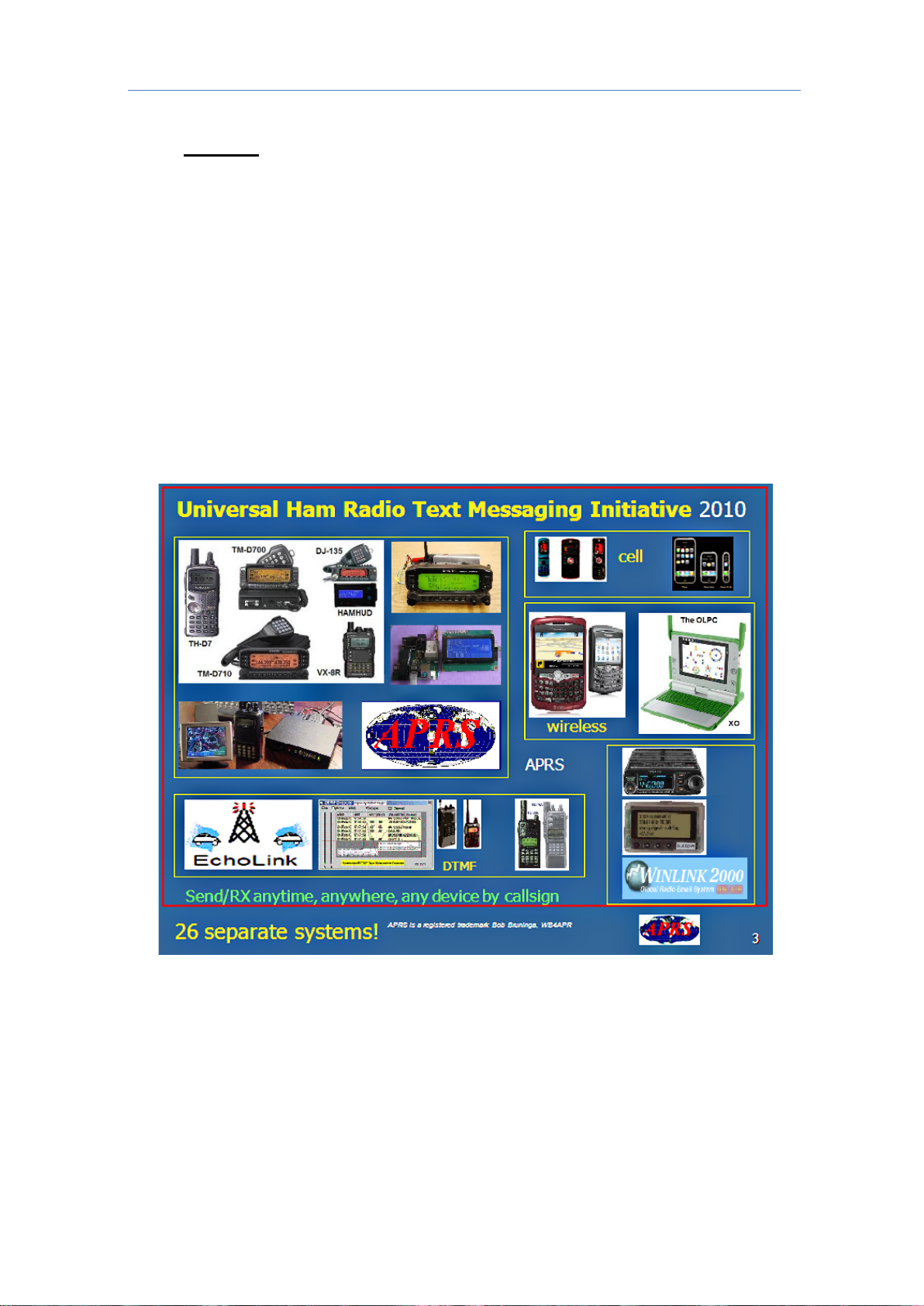
2.7 TEXTING .............................................................................................................................. 12
2.8 FACEBOOK ON APRS ........................................................................................................... 13
2.9 APRS VOICE ALERT ............................................................................................................. 13
2.10 FREQUENCY DATA FIELD AND AUTO-TUNE (OR QSY) ........................................................ 14
2.11 VOICE REPEATERS AND CLUB INFO...................................................................................... 15
2.12 HAMFEST TALK-IN AND OBJECTS ......................................................................................... 16
2.13 VOICE OVER INTERNET PROTOCOL (VO-IP) AND D-STAR ..................................................... 17
2.14 DIGIPEATER PATH INFORMATION .......................................................................................... 18
2.15 OTHER APRS INFORMATION RESOURCES ........................................................................... 18
2.16 CONTRIBUTION BY KENWOOD TO APRS ........................................................................... 19
2.17 LIST OF ICONS THAT CAN BE SET / DISPLAYED ON THE TH-D74A/E ........................................ 21
3 APRS ................................................................................................................................... 22
3.1 APRS FEATURE ON THE TH-D74A/E .................................................................................... 22
3.2 WHAT IS A KISS MODEM? ..................................................................................................... 24
3.3 KISS MODE ......................................................................................................................... 26
4 ENJOYING D-STAR (BY DON ARNOLD, W6GPS) ........................................................... 28
4.1 ENCOUNTER WITH D-STAR .................................................................................................. 28
4.2 ENJOY WITH D-STAR ........................................................................................................... 29
4.3 D-STAR REFLECTOR OPERATION ......................................................................................... 30
4.4 ABOUT THE TH-D74A/E ....................................................................................................... 32
5 D-STAR ................................................................................................................................ 33
5.1 BASIC OPERATION ................................................................................................................ 33
5.2 COMMUNICATION USING D-STAR ......................................................................................... 33
5.3 COMMUNICATING USING A REPEATER .................................................................................... 35
5.4 CONFIGURATION FOR REFLECTOR NODE ............................................................................... 38
5.5 HOW TO UPDATE THE REPEATER LIST .................................................................................... 41
6 SETTINGS & CONTROLS .................................................................................................. 45
6.1 EXTENDING THE BATTERY LIFE .............................................................................................. 45
6.2 SILENT APRS AND PACKET COMMUNICATIONS (VOICE ALERT) ............................................... 46
6.3 SCREEN CAPTURE OF RADIO DISPLAY ................................................................................... 46
6.4 VIEWING MICROSD CARD ON PC .......................................................................................... 47
6.5 ADJUSTMENT OF RX AUDIO QUALITY ..................................................................................... 47
5
Page 6

ADJUSTMENT OF TX AUDIO QUALITY ..................................................................................... 48
6.6
6.7 WIDE-BAND AND MULTI-MODE RECEPTION ............................................................................. 48
6.8 MODE .................................................................................................................................. 51
6.9 MEMORY CHANNELS ............................................................................................................. 53
6.10 BLUETOOTH ....................................................................................................................... 55
6.11 USB USAGE ....................................................................................................................... 56
6.12 MICROSD CARD USAGE ..................................................................................................... 57
7 APPENDIX ........................................................................................................................... 62
7.1 EXTERIOR VIEWS .................................................................................................................. 62
7.2 TH-D74A/E SPECIFICATIONS................................................................................................ 63
6
Page 7

1 Getting Started
1 Getting Started
1.1 For publication of this document
This manual has been developed with the user of the TH-D74A/E in mind. Its intent is to
enable the user to enjoy the features of their radio in both APRS and D-STAR. In addition
to the information shared on the TH-D7 4A/E, descriptions are provided on the MCP-D74
software.
Like the previous and existing handheld model s, the TH-D7A/E and TH-D72A/E equipped
with the A P RS feature set, these models and their predece ss ors were developed for data
communications along with voice. With the TH-D74A/E series, these features have been
greatly enhanced and expanded to make operation easier for both new and experienced
APRS users. Not only the enjoyment received by the use of APRS, D-STAR has been
added to offer true digital communications. D-STA R was developed by the Japan Amateur
Radio League (JARL) as a digital protocol for am ateur radio.
We have placed great ef forts in the development of high-performance and high-functionality
equipment that offer power and performance. The TH-D74A/E is equipped with a high
visibility, color transreflective liquid crystal di splay (TFT), the first in the industry in a
handheld amateur radio (as of November 2017). Building on the popularity of the
wideband frequency receive feature of the TH-F6A/F7E, the TH-D74A/E supports DSP
processing for CW / SSB reception with the added addition of IF bandwidth filtering.
Features such as APRS and D-STAR require positio nal i nformation from the transceiver the
TH-D74A/E has a highly-sensitive internal GPS re ceiver. As with the previous and existing
models, GPS Log Mode is available to track movement.
The TH-D74A/E supports the USB interface, Bl uetooth, and a microSD card slot for easier
programming, data transfers, and genera l communications b etween periphe ral devices such
as your computer or tablet.
These features of the TH-D74A/E enhance the user experience and will be explained more
in the following pages. Please read through this document along with your User Manual to
better understand how to best enjoy your radio.
http://manual.kenwood.com/en_contents/search/keyword.
TH-D74A/E Development Team, December 2017
ote) This manual (PDF version) is the addition of drawings and images to the contents of
N
the booklet distributed at "DAYT ON HAMVENTION 2017"
.
7
Page 8
2 ENJOYING APRS (by BOB BRUNINGA, WB4APR)
2 ENJOYING APRS (by BOB BRUNINGA, WB4APR)
2.1 APRS Overview
The TH-D74A/E APRS / D-STAR h andheld transceiver is the latest in the long series of
KENWOOD APRS radios and it brings the whole new dimension of digital voice (D-STAR)
that not only allows the internal global data and m essaging by callsign (APRS) but now
global Voice by callsign through D-STAR networks. It is hard to fully grasp what this power
can bring to Amateur Radio operation once these radi os are in the hands of the motivated
operator and experimenter . The radio continues the evolution of the fundamental principles
of APRS as a common information resource channel for facilitating human-to-human
communication and now voice. To see how this fits in, it is first necessary to un derstand
the history of APRS and packet radio.
2.2 Packet Radio History
The roots of the Automatic Packet Reporting System (A PRS) go back to the late 1970s as
the AMRAD (Amateur Radio Research and development) Group was excitedly beginning to
experiment with AX.25 packet radio. This was before the Internet, and as we spent our
free time in our shacks, we were in fact all socially-networked by the AMRAD voice repeater.
On evenings and weekends, someone was worki ng on something or developing something
new and sharing the excitement with the others on the repeater channel. We hung onto
our handheld transceivers everywhere we went like kids these days hang onto their iPads
and smartphones to keep up with the excitement .
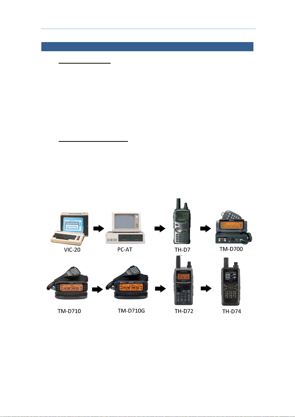
story of APRS from VIC-20 to TH-D74A/E
The Hi
nce only RTTY was legal in the USA at t he time, we developed a RTTY chat channel to
Si
augment our repeater communications. We wanted a digital channel that worked just like a
voice repeater. That is, anyone who had info transmitted it, and everyone monitoring
captured it. Advancing from RTTY, AMRAD developed the AX.25 spec and as soon as it
was legal, we were on the air as a chat group using real-t i m e Unconnected Information (UI)
packet messaging. One field activity of this technical group was the annual
8
Page 9

2 ENJOYING APRS (by BOB BRUNINGA, WB4APR)
communications support for the Old Dominion 100 mile endurance run. For this event in
the mid1980s, the first vestige of APRS used Vic-20s and packet radio to share information
on the hundreds of runners and horses across the hu ndreds or so square miles over the
24-hour event.
There was no such thing as GPS. The system consisted of simply a packet channel where
each checkpoint beaconed information and obj ects about arrivals and then transferred
object responsibility as it was taken over by the next checkpoint. At any instant, everyone
could see on their screens, a list of the objects reported at each station and their status.
New information was beaconed at a high rate for immediate delivery but decayed rapidly to
reduce channel loading so that fresh information had priority with minimum collisions.
This was the core concept that became APRS.
2.3 Packet Network Growth
Beginning in 1983, we added VHF, HF and a phone line to the club packet BBS to provide a
store and forward capability and began expanding to the Commodore 64. It was linked
with other systems on 145.01 MHz and had the first dual-port HF link onto the 10.149 MHz
HF packet frequency we still use today for APRS. It was an exciting time, but packet radio
was being used more and more for connected point-to-point traf f ic and then to B BS system s
and the real-time connectivity between operators was bei ng lost. By that time, live beacons
to announce real-time activity and to conduct group chats by UI messaging was not only
disappearing but were actually being outlawed on the congested/shared BBS channels.
Even UI digipeating was being disabled in all packet nodes to make sure that no one
beaconed or chatted on the BBS network and dozens of restricted/exclusive use packet
frequencies. Everything was evolving to store-forward mess agi ng (like internet email
became over the next decade) and real-time digit al human connectivity was lost.
But we still wanted that live operator-to-operator UI packet chat capability and we still
needed a tactical real-time local communications and information distribution channel for
rapidly exchanging digital data of immediate value to local operators and operations. In
1992, we abandoned the Commodore 64 and switche d to the new IBM AT personal
computer running at 4 MHz and changed the name from the Connectionless Emergency
Traffic System (CETS) to Automatic Packet Reporting System (APRS) since it matched my
callsign so nicely.
9
Page 10
2 ENJOYING APRS (by BOB BRUNINGA, WB4APR)
2.4 APRS in 1990s
I formally presented APRS at the TAPR/ A RRL Digital Conference in 1992. APRS really
took off as the cost of GPS got bel ow $500 each and I manually digitized maps of the ent i re
U.S.A. and some other countries using coordin ates measured from paper maps. It was
during these times that the “P” in APRS was temporarily called “Position” to highlight this
new capability. Unfortunately, this was a mistake.
Over the next decade as GPS became readily available, too many hams only saw the
position maps of APRS and not the broad communication applications for human-to-human
tactical ham radio information exchange in real time.
Too many operato rs bought transmit-only GPS trackers and further i gnored the real-time
human communications element. Many follow-on software clients focused on maps with
little attention to the underlying network proto col and live human-to-human connectivity both
local and global.
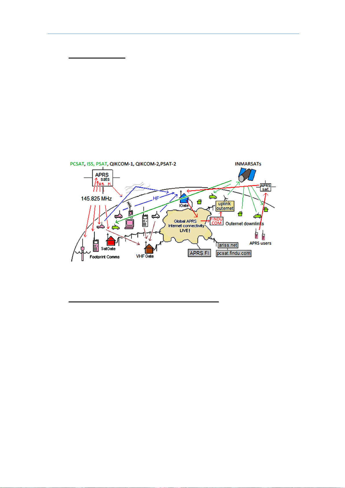
but the APRS-IS collects information from local IGates and shares the information worldwide.
The APRS network is primarily designed for local real-time operations,
2.5 APRS-IS res the information worldwide
In 1997, K4HG Steve Dimse and the Mac/WinAPRS Sproul brothers tied APRS to the
Internet and the APRS-IS system as shown above was born. Over the years the network
has grown including several Amateur Satellites since 2001 and in 2015 even an APRS
channel with global downlink coverage via the Inmarsats called Outernet.
See http://aprs.org/outnet.html
While this was a huge success that enabled instantaneous global APRS texting connectivity
worldwide, it also further enhanced the map vi ew experience of casual APRS viewers.
Looking at an APRS map was colorful but it still did not obviously convey the real-time
human contact and connectivity inherent i n the system. Also, it was impossible to
communicate with all of the one-way trackers equipment which had no receivers.
The value of two-way amateur radio communications was further being lost in favor of
simple one-dimensional icons on maps. These simple icons omitted the other 8
dimensions of color attributes associated with each APRS symbol that gave additional
at-a-glance real time information to viewers suc h as type, age, moving-or-static,
object-or-station, ownership, and liver-operator or m essaging capability.
See http://aprs.org/symbols.html
10
Page 11
2 ENJOYING APRS (by BOB BRUNINGA, WB4APR)
2.6 APRS Handheld and Mobile Radios
To counteract thi s t rend, we stopped using “Position” for the "P" in APRS and went back to
the original “Packet” nomenclature for the "P" in APRS. Then in 1998, KENWOOD gave a
landmark boost to A PRS in the field and to this two-way digit al communication s capability by
introducing the fully integrated TH-D7A/E. This TH-D7A/E put APRS in the palm of the
hand of ham radio operators worldwide. Not only did it take GPS inputs, but it fully
implemented the APRS messaging, bulletins and texting capabilities at both 1200 and 9600
baud.
Over the next 11 years, this first KENWOOD APRS radio was the most popular KENWOOD
HT ever as APRS brought new life to packet radio.
In parallel, KENWOOD also introduced the fully integrated TM-D700A/E mobile APRS radio
in 2000. These APRS front-panel-display radios now brought the full APRS local
situational awareness to the mobile operator as shown below. With these displays, the
APRS information content delivery system was in place without any need for mobile PC’s or
laptops. Further, the attached GPS provided the map display and the radio display
provided all the other information content .
11
Page 12
2 ENJOYING APRS (by BOB BRUNINGA, WB4APR)
2.7 Texting
But still, most non APRS ham radio operators just did not see any advantages beyond the
maps. My frustration with the growing lack of live human content in APRS continued to
fester to the breaking point at a 2006 ARRL Special Meeting at Dayton on the lack of yout h
in ham radio.
The gathered fathers of ARRL lamented: “Ham radio was missing the youth”. They were
“too busy texting on their cell phones” and “ham radio had nothing similar to offer”. I was
flabbergasted. Ham radio had had a wireless texti ng/email handheld device for nearly a
decade since 1998 in the form of the handheld KENWOOD APRS TH-D7 A/E and yet even
the amateur radio leadership was not aware of t hese capabilities and had never tried it.
This was frustrating. While the older hams were shunning real-time APRS digital text
communications with APRS, and handheld Photo-sharing u sing the KENWOOD SSTV
handheld, the kids of the world were just getting going with texting and Photo-sharing then
Twitter on every conceivable handheld device or exchanging handheld pictures with the
VC-H1.
Yet the entrenched amateur radio ol d timers could not see any value to APRS texting and
emailing on a keypad.
As mentioned in the above illustration, there a re m ore than 26 different text syst em s being
used in Amateur Radio (which do not talk to each other) as sugges ted in the image above.
Fortunately, today just about every smartphone and handheld does have an application for
APRS message compatibility . Our goal i n APRS is to seamles sly i nt egrate t h ese disjoi nt ed
systems so that a message-to-callsign from any devic e gets delivered to the callsign owner
on any device that is currently turned on. Many of these systems are already connected by
APRS and the APRS-Internet system (APRS-IS).
Refer to http://aprs.org/aprs-messaging.html
12
Page 13
2 ENJOYING APRS (by BOB BRUNINGA, WB4APR)
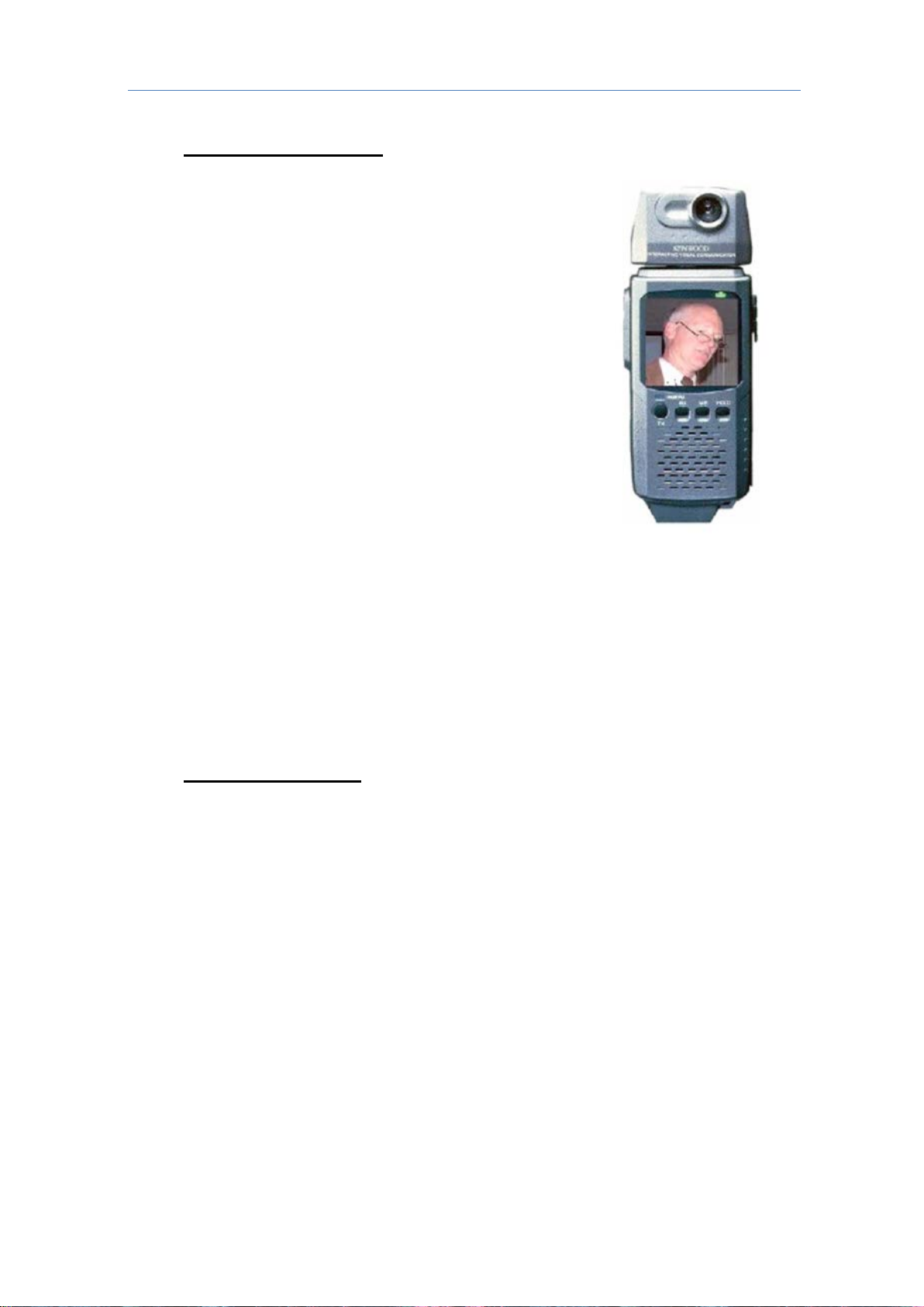
2.8 Facebook on APRS
Purely as an aside, you can think back to the KENWOOD VC-H1
handheld SSTV device as an attempt (before its t i m e) to add the
visual aspect of social networking to ham radio and APRS.
This was a fantastic idea. And it was fully integrate d i nto all
KENWOOD APRS radios at the time, adding real-time video to
APRS digital and texting connectivity. You could think of the
combination as real-time “Facebook” on APRS.
Unfortunately it was ahead of its time and the VC-H1 handheld is
no longer in production, but thousands of hams have them and
still use them. These SSTV handhelds along with readily
available free SSTV software make a great visual adjunct to
APRS which could pass through any voice channel or repeater.
This was in the early 2000 time frame bef ore a ny one had c ame ra
phones. Think of the potential.
The concept was to snap an image, and send it into APRS
where it was picked up by a web site that cataloged it by position,
originator and a text description for viewing by anyone.
This can be a tremendous asset for ham radio public service.
There are a few such active links from APRS and SSTV t o the
web called the Automat ic Picture Relay Network, or AP RN.
Although most hams do not have the KENWOO D VC-H1, there has been a revolution in
smart phones and now anyone anywhere can use t heir smart phone to send and receive
SSTV images simply via the camera in the phone and an SSTV application software that
can then convert the image to tones and transmit it over any of the KENWOOD handheld or
mobile radios. Similarly, any such phone with the SSTV application can use t he phone to
decode the audio and display the SSTV image. Thus, anyone with a smart phone and a
2-way radio and a radio voice channel can still send images by amateur radio!
Refer to: http://aprs.org/aprn.html
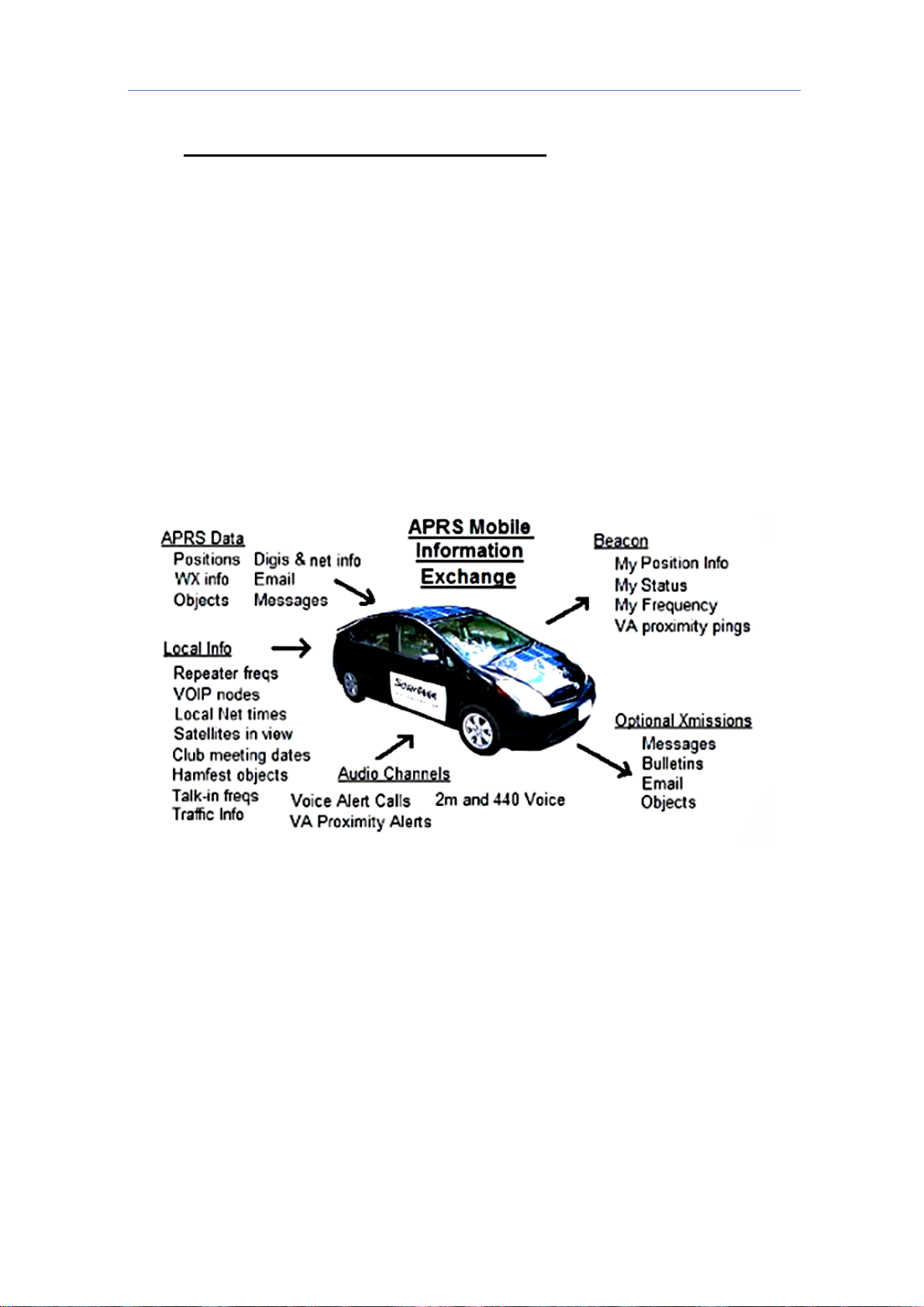
2.9 APRS Voice Alert
Three things dramatically brought back human connectivity to APRS. The first factor was
Voice Alert. The second was the addition of a frequency field in all APRS position packets.
And the third was the emergence of VOIP Internet/ham radio linked voice.
Voice ale rt is like a 3rd sim ultaneous ra dio chann el on the KENWOOD APRS transceivers. It
acts like an intercom channel for all APRS operators to be able to quickly raise another
nearby APRS voice alert stat ion by a simple di rect voi ce call. I t required no ne w hardwa re or
software. It simply consists of setting CTCSS 100 Hz on the APRS data channel and
keeping the speaker volume up. This way, all packet noise was completely muted, but the
operator could still be called at any time with a CTCSS 100 Hz voice call. A secondary
benefit to this technique was a free proximi ty detector. If any other Voice Alert station got
within simplex range (maybe 5 miles or less in a mobile) his periodic packets would give an
audible alert. These new features of APRS Voice Alert as indicated in the APRS Mobile
information Exchange drawing above finally m ade i t easy to keep the eyes on the road, but
never miss the opportunity for human contact wit h a fell ow AP RS operato r on the open road.
Voice Alert i s easiest enabled and disabled by simply storing two separate Mem ory channels
on the national APRS frequency. One with CTCSS 100 and the other without.
13
Page 14
2 ENJOYING APRS (by BOB BRUNINGA, WB4APR)
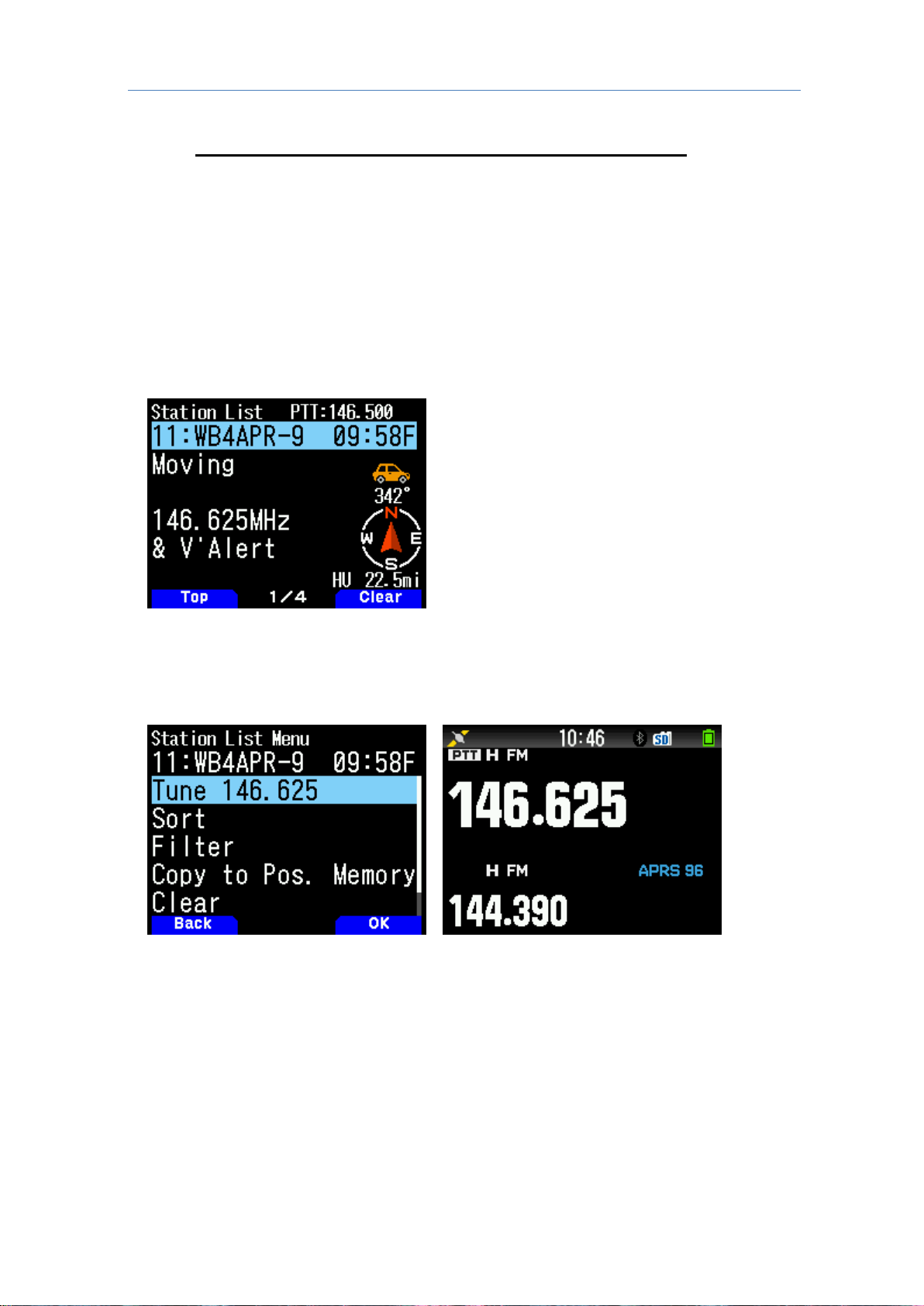
One is the TUNE function shown on the
screen above.
As in the third image, when TUNE is
selected, the radio automatically tunes t o
the frequency of the second band
(non-data band).
2.10 Frequency Data Field and AUTO-TUNE (or QSY)
At the nearly same time as we introduced Voice Alert (2004), the Frequency fiel d was added
to the A P RS posit i on packet specification. This standardized the inclusion of a voice
operating frequency in the APRS system. APRS was never intended as an end-in-itself,
but as a tool to be applied to all aspects of ham radio and human contact.
Knowing other station’s voice contact frequency in many cases is even more important for
establishing communications than knowing position. Now every ham could announce his
monitoring frequency in his APRS packet and could call others on their indicated frequency.
KENWOOD was the first to leverage the value of this capability by introducing i t in all of their
APRS radios since 2007 (the TM-D710A/E, TH-D72A/E TM-D710GA/E and TH-D74A/E).
These radios not only automatically include your v oice band frequency in every position
packet but can also then tune to someone else’s, frequency by simply selecting the “Tune”
menu as shown below:
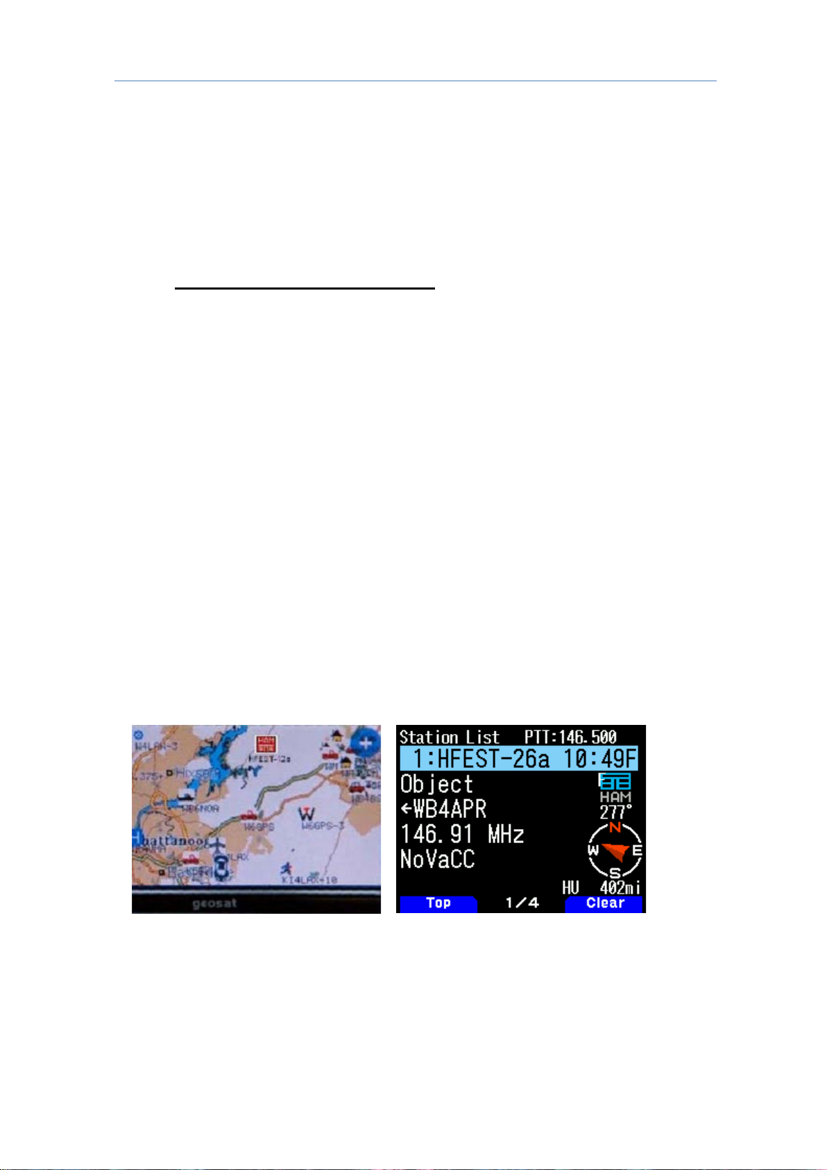
In the image above, stations with frequencies em bedded in position information packets are
displayed on the screen. This station is the eleventh station in the list, transmits a beacon
of the operation frequency of its own station, and transmits a short message informing other
stations that they are also listening to voi ce alerts within the simplex communication range.
In this screen, use the [MENU] key to recall multiple additional functions.
14
Page 15
2 ENJOYING APRS (by BOB BRUNINGA, WB4APR)
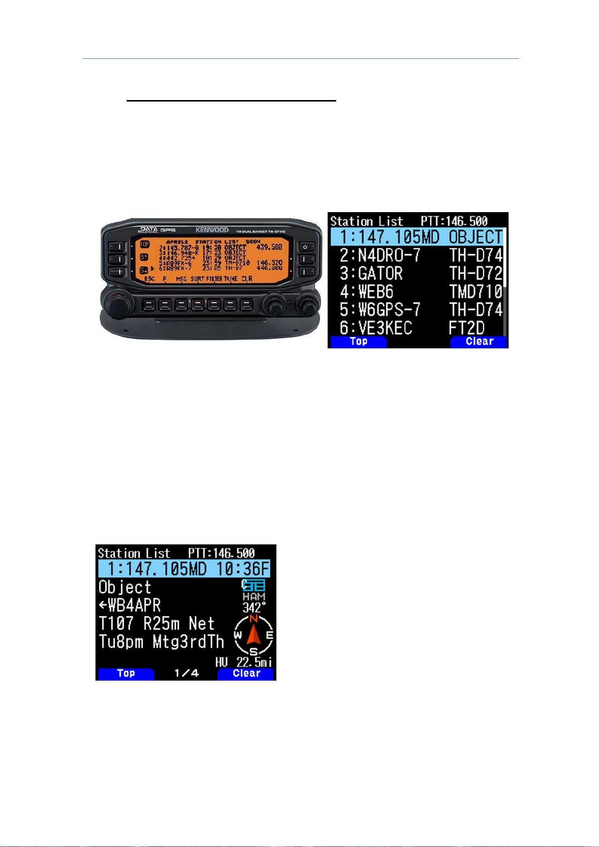
2.11 Voice Repeaters and Club Info
Besides alerting others to the voice monit oring frequency of other APRS operators, the
addition of the Frequency field to APRS opened up a whole ne w application of local
information for the mobile operator. Now everywhere the APRS operator travels, he can be
alerted to the recommended traveler’s voice repeater in any area he was passing through.
This is accomplished by not only having every digip ea ter bea con i ts position and avai labilit y,
but also by beaconing this local frequency object.
These frequency objects show up in the station li st of all mobile ope rators in range as s hown
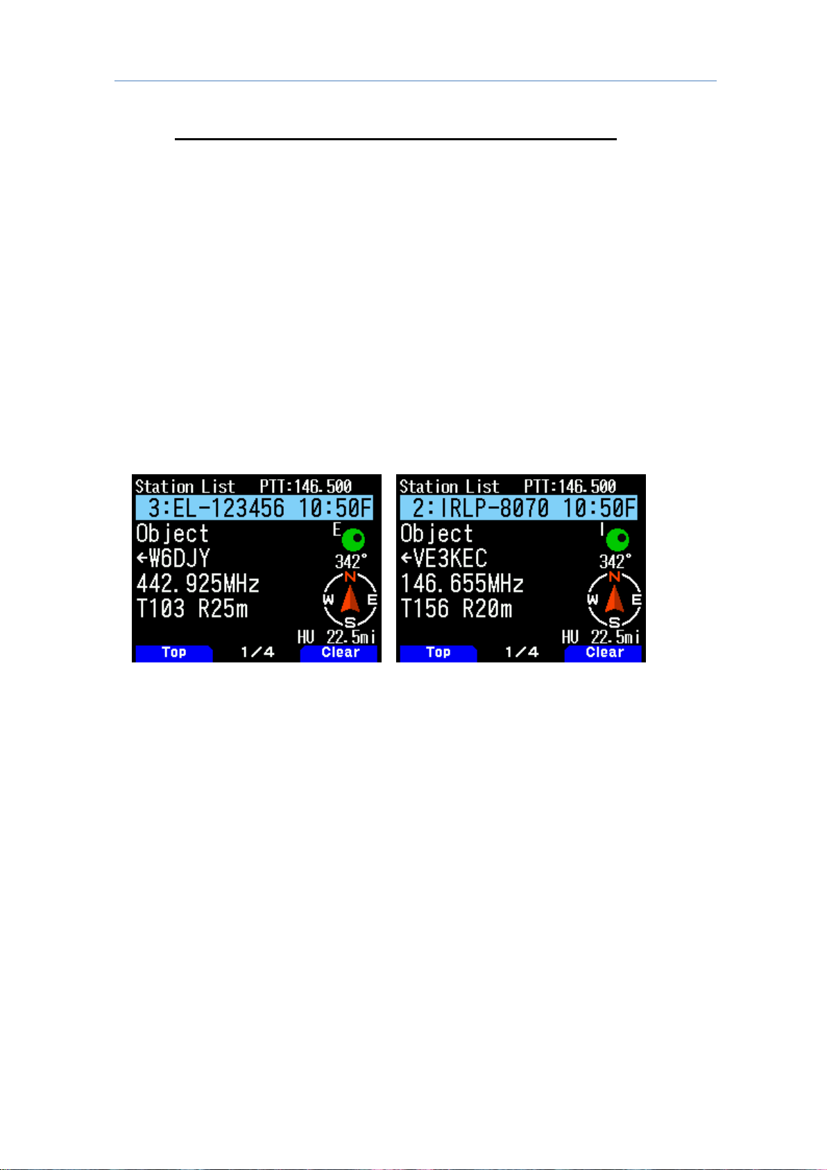
below in the TM-D710A/E, TM-D710GA/E and TH-D74A/E front panels:
O
n the TM-D710GA/E station list as above, not only are the two stations of AB9FX nearby,
but also his current VOICE operating frequency i s visible.
Also, we can see that this radio is in OPERATING range of three voice repeaters that are
also identifying themselves as objects on APRS as the locally recommended voice
operating channels.
The TH-D74A/E on the right has two ham calls, two t act i cal calls and one repeater object.
It is easy to find these nearby frequencies in the huge station list by first doing a SORT.
This brings all the numeric objects (in this ca se, frequencies) to the top of the list as shown
on the TM-D710GA/E on the left.
The standard for these frequency objects also includes Tone, Shift, and bandwidth for
instant tuning. In addition, they can include t he we ekly on-air v oice net times as well as th e
monthly club meeting dates as shown below, all in a single periodic beacon object:
lthough the information appears a bit cr yptic, the fact that all voice repeater obj ects use this
A
same standard format makes it easy for the operator to understand the meaning.
In this case, the local recommended voice repeater in this area is the 147.105 MHz
(Maryland) repeater with a Tone of 107.2 Hz.
15
Page 16
2 ENJOYING APRS (by BOB BRUNINGA, WB4APR)
The repeater's range is 25 miles and the weekly net time is Tuesday evenings at 8 p.m.
The final 8 characters (limited for backwards compatibili ty to TM-D700A/E) announce that
the club meetings are on the 3rd Thursday of every month.
Again, a press of the [MENU] key and then selecting “Tune” will instantly take the radio to
this channel. For full details on this function, ref er to the following website:
http://aprs.org/localinfo.html
2.12 Hamfest Talk-in and Objects
APRS should be a primary tool of any Hamfest talk-in station.
Alongside the voice operator should be an APRS operator managing the local APRS tactical
map with the locations of all the special objects associated with the Hamfest.
In addition this A PRS ope r ator help s the voice operat or see where t he mobil e chec k-ins that
are lost are located so he can give them voice guidance to the Hamfest.
The most important APRS object is the one that shows the location of the HAMFEST and
the talk-in frequency. This bright red APRS symbol stands out smartly on any APRS
display including the AvMap GPS display as sho wn above. At first glance, this object tells
you the most important information: Where it i s, and when.
The HFEST-DDn standardi zed object name includes the DATE in the DD digits. Only the
day is shown (here it is on the 26th), but this allows for 2 weeks notice to everyone in the
area and anyone driving through.
The final character “n” is chosen to make the symbol unique in the global APRS system so it
is not overwritten by other Hamfests on the same d ay somewhere else.
This makes for easy sorting of these objects. Sim pl y go to http://aprs.fi/hfest * and see a
list of all active Hamfest the world over!.
The talk-in frequency is also listed for instant QSY with the TH-D74A/E “Tune” function. I
was on a cross-country trip one day on a weekend and j ust happened to see one of these
objects and was able to detour and spend an hour or two at this favorite ham radio pastime.
To see how to beacon your local Hamfest, refer to the following website:
http://aprs.org/hamfest.html
16
Page 17
2 ENJOYING APRS (by BOB BRUNINGA, WB4APR)
2.13 Voice over Internet Protocol (Vo-IP) and D-STAR
Recognizing the huge potential for linking local ham radio over Internet, an added goal of
APRS since 2001 has been to facilitate the integration of Digi tal Voice Systems and allowing
end-to-end voice contact while using APRS global messaging cap abi l i ty to help set up the
calls. Initially, this was via the use of IRLP, EchoLink, and other VoIP systems.
Now with the TH-D74A/E, this can include D-STAR.
Just like the Frequency Objects, all ham radio VoIP systems are encouraged to announce
their presence on APRS. Within 10 minutes t he node number, frequency, tone and other info
are available to all APRS operato rs on thei r radios as shown above . Again, a simple press of
the “Tune” function will QSY the radio for instant operation.
The long-term goal of this VoIP and Frequency capability has been to enable APRS to be
used for setting up end-to-end global contacts using only a known callsign. The idea was
to simply enter a callsign in a contact-request message will cause the APRS Internet system
to handshake with the VoIP systems to set up the call and send the necessary QSY
messages and frequency information for the radio to instantly tune and complete the call.
Think of it as a cellular system for ham radio where you dial by callsign instead of phone
number. Both TM-D710GA/E and TH-D74A/E were designed to be evolved with this
capability.
17
Page 18
2 ENJOYING APRS (by BOB BRUNINGA, WB4APR)
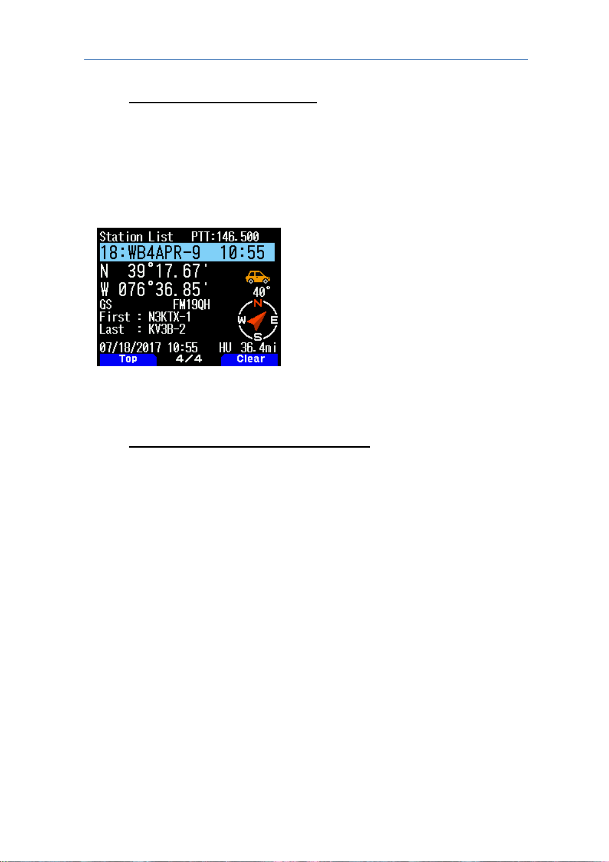
There are 4 pages of information about each station received by the TH-D74A/E
and imported into the station list, and
displayed on the 4th page.
2.14 Digipeater Path Information
Another new information feature included i n the TH-D74A/E is the digipeater path displ ay
shown here so the recipient can understand the local network and how a given packet was
routed through the APRS digipeater network. This display shows the First and Last
digipeaters used.
Most APRS areas encourage the use of only 2 hops or less. This means, in most cases, the
full path is visible. In this image the WB3V-6 packet was first heard by the N3KTX-1
digipeater and then it was delivered to my radio by the Last hop on the KV3B-2 digipeater.
This path knowledge is very valuable to the operator in understanding his local area
network.
the display of this digipeater / pass is
2.15 Other APRS Information Resources
The information available to the mobile operat or via AP RS i s nearly unlimited but not if no
one is transmitting it. Ideally local info is only transmitted direct, with no path hop s from t he
local digipeater and no more often than once ev ery 10 minutes to give a chance for a new
mobile to get it. If the local info has to be digipeated once, then it is a longer range and the
rate should drop to every 20. If it is sent regionally via 2 hops it should only be once every
30 minutes which is still possible for a 60 MPH traveler to be within range of 2 digipeaters
and get the info. There is plenty of room for additional content when properly added to the
local channel. This is not spam, but real immediate information of value to the mobile or
traveler. There are many examples of data sources that have been implem ented in some
local areas. For example,
-Traffic speeds at select choke points: refer to: http://aprs.org/traffic.html
Mobile Satellites view: refer to: http://aprs.org/satinfo.html
-MF
I-InfoKiosk local info database: refer to: http://www.apritch.co.uk/addon_uiview32.htm
-U
-APR
S client for windows refer to: http://aprsisce.wikidot.com/clients
18
Page 19

2 ENJOYING APRS (by BOB BRUNINGA, WB4APR)
2.16 Contribution by KENWOOD to APRS
KENWOOD has developed its series of radios, TH-D7A/E, TM-D700A/E, TM-D710A/E,
TH-D72A/E, TM-D710GA/E and now the new TH-D74A/E to best support the original
objectives of APRS.
The real-time display of A P RS i nformation on the front panel of these radios gives t he
mobile operator instantaneous access to all l ocal i nformation being provided on the APRS
channel about all surrounding ham radio activ i ties.
There are many APRS clients and programs that have been written that sometimes have
concentrated too much on the display of maps and vehicle positions while leaving out much
of the original fundamentals of APRS and the efficiency of the APRS network.
The KENWOOD radios avoid such an over-simplistic approach to APRS by implementing a
rich and diverse function set. The function set includes almost all of the original functions
of APRS that are meant to reinforce the concept of distributin g l ocal information.
The KENWOOD radios are not just Vehicle Tracking Systems, but are designed to be
real-time information distribution systems for mobile operators with these features:
Position Entry
TH-D74A/E with its built in GPS solves the hassle of external connections and setup and
always accurately knows your position.
For times indoors the radio has 5 position memories for pre-stored frequently-used
positions.
APRS Network Fundamentals
KENWOOD fully implemented the more subtle aspects of the APRS fundamentals that
assure optimum network efficiency and channel sharing among all users.
New TH-D74A/E supports the decay algorithm, proportional pathing and SmartBeaconing.
These techniques provide good refresh rates for new and local information while
minimizing the network impact of old and distant data.
Objects (NEW)
The KENWOOD transceivers fully appreciate the value of APRS objects and display them
prominently. The object location is shown just li ke other stations either on the attached
map display or on the front panel with distance an d range.
Not only does the TH-D74A/E also include filters for easy sorting of these objects in the list,
this radio is the first one to have the ADD OBJECT function so that users in the f ield can use
only their handheld to place important objects on the map.
These objects are what give APRS the local information value to local users.
Two-Way Messaging
Unlike passive one-way tracking devices, the KENWOOD radios provide the mobile user
with full two-way messaging and display.
This real-time human-to-human communications is what makes APRS so valuable in
support of special events and emergencies.
Field Data Entry
In addition to making excellent field data display devices, the TH-D74A/E menus have
also been designed for easy data, position and message entry.
Often overlooked is the ability to use TH-D7A/E, TM-D700A/E, TM-D710A/E and
TM-D710GA/E as excellent field data entry and clipboard entry devices at many field
events.
Refer to: http://aprs.org/aprsevent.html
19
Page 20

2 ENJOYING APRS (by BOB BRUNINGA, WB4APR)
Individual Information Access
The KENWOOD individual radio displays enhance the dist ri bution of ham radio
information to a large number of users by giving them individual front panel and keypad
access to all of the online APRS data.
A common m istake of fixed operations with computers is the use of large display screens
for large groups to see but which fails to recognize the individual needs of a given viewer
and the depth of information available under each symbol on the map.
The individuality of APRS radios with individual display s spreads this data access
throughout the users in the field.
Overlay Characters on all Symbols
The KENWOOD TH-D74A/E shows the overlay character of all symbols, not just the
original subset of special symbols.
This provides hundreds of new symbol combinations for better APRS application to new
uses.
Voice Operating Frequencies
A very i mportant feat ure of the new TH-D74A/E is the recognition of the value of the voice
operator frequency as a fundamental communications parameter.
Not only does the radio automatically include its own voice band frequency in every
transmitted position packet, it also has special displays and features that make this
information readily available. For example, the station list can be sorted to bring
Frequency Objects to the top of the list in f requency order. Further, the radio can tune to
these frequencies for quick QSO with a single press of the “Tune” menu.
EchoLink, IRLP, Winlink or D-STAR Frequencies
The TH-D74A/E “Tune” function not only makes rapid QSY to another station operator
easy, it also facilitates quick tuning to nearby EchoLink, IRLP, Winlink or D-STAR
frequencies with the push of a single key.
Future use of this capability is anticipated to automatically and seamlessly integrate
callsign-to-callsign calling from RF via local, national and global ham radio V oIP and
D-STAR systems.
No
tes:
If all you think of when you hear the word APRS is maps and st agnant icons, then you are
not using the full potential of APRS.
If all of the local information that can be of i m m edi ate value to the APRS HT or mobile
operator is not showing up in your local area, t hen get active and get involved in supplying
this content and updating all local digipeaters to supply it direct to users without multiple
hops.
APRS is a communication tool, not just an automat ed map. Use it. But in most cases,
that means entering data, not just watching it.
KENWOOD has provided the APRS handheld and mobile information display capability, it is
up to us to provide content!
September 2017
WB4APR Bob Bruninga
20
Page 21

2 ENJOYING APRS (by BOB BRUNINGA, WB4APR)
Person Fire Truck Red Cross EchoLink
Bicycle Canoe Lighthouse Node
Motorcycle Boat Speedpost GATEway
Car Sailboat WorkZone DF station
Bus Balloon
Wreck/
Obstruction
Dish
Antenna
Railroad
Engine
Glider Sheriff PC user
Home Helicopter Fire SSTV
Yagi@QTH Aircraft Sunny ATV
KENWOOD
Large
Aircraft
Gal e Fl ags BBS
Radio Shuttle Tornado APRStt
RV Satellite
Nat ion al WX
Serv ice Site
RACES
Van Rover
WX
(Weather
Station)
ARRL
Jeep Eyeball Digipeater X
Truck
Portable
(Tent)
Mic-E
Repeater
Triangle
Truck
(18-wheeler)
HAM Store
QSO
Repeater
Small
Circle
Police School Circle Red Dot
Ambulance Hospital IRLP
Big
Question
Mark
2.17 List of icons that can be set / displayed on the TH-D74A/E
(The icon designs below are supervised by Mr. Bob Bruninga, WB4APR)
21
Page 22

3 APRS
(→
3 APRS
3.1 APRS Feature on the TH-D74A/E
This section will introduce you the many enhanced APRS features of this new digital
portable.
Relative Direction Display (Ne w Feature) 3.1.1
While the TH-D72A/E also comes with a feature that shows the dir ection in which the target
station is located relative to my station, the display of this feature has been enhanced
significantly on the TH-D74A/E. The direction in which my station is advan cing is displayed
at the center of a big compass, while the direction in which the target station is located as
well as its advancing direction is shown on the circu mference for easy identification.
The display can also be toggled between North Up and Heading Up by pressing
key. Based on the display, it is possible to figure out whether the target station is
[F]
moving toward the same advancing direction as m y station.
Example: When W4DJY-9 (target st ation) is located at 45 degrees from my station and
moving south-eastward at a speed of 70 mph.
ransmission of Object/Item Information (New Feature) 3.1.2
T
The TH-D74A/E supports transmission of object and item i nformation.
"Object information” transmission of object and i tem information. Not possess a radio, like
a hurricane or a marathon runner. These objects are characterized by a time stamp they
possess.
"Item information”, like a hurricane or a marathon location, these do not have a t i m e st am p.
Object and item information are transmitted using the predefined object name and item
name respectively. When data of an object or item is received, the object name or item
name appears in the Callsign display area.
Live Object/ Live Item
When sending out information on an object or item , configure "Type" to Live Object or Live
Item if the information is only valid for a certai n peri od of t ime (e.g. , period when a hurri ca ne
exists, period when a marathon race is held).
Killed Object/ Killed Item
When the information is no longer valid, t he user who has sent out the object or item
information must select Killed Object or Killed Item as "Type" and send out the obje ct data
or item data.
Menu No. 516)
22
Page 23

3 APRS
Disclosing Audio Standby Frequency (QSY Feature) 3.1.3
APRS makes use of a wide-band data frequency, which basically cannot be used for audio
communication. Therefore, disclosing the f requency that can be used for audio
communication helps to facilitate the communicat ion proce ss. For example, during
communication at remote locations such as in a m ountain, announcing the frequency for
audio communication via the APRS beacon makes it easier to establish communi cati on with
a nearby amateur radio station.
Let us look at how we can carry out audio communi cation on band A and APRS data
communication on band B. In general, positional information on of one's own station is
transmitted periodically as an APRS beacon in the case of band B. In this case, it is
possible to embed the frequency information of a non-data band (band A in this example) in
the APRS data. This is known as the QSY feature.
When sending out information such as like that of the a audio repeater and or EchoLink as
QSY information, informati on on Tone/ Shift/ Wide can also be appended applied as
needed in addition to the frequency information.
"F" is displayed when APRS received data that contains QSY information. The user at the
radio station that has received the data can operate the “Tune” function to shift the
non-data band to the VFO mode, which enables the frequency to be adjusted automatically
according to the audio frequency of the other station.
Sending out QSY information in this way by this method easy and very certain way of
shifting the other station to the audio communication channel.
isclosing D-ST AR St andby Information with the QSY Feature (New Feature) 3.1.4
D
The TH-D74A/E also allows disclosure of the D-STAR standby information using the QSY
feature.
Operating the “Tune” function of the station that has received the D-STAR standby
information enables the information of the station to be adjusted automatically according to
the D-STAR configuration information of the transmitting station.
For example, during D-STAR audio communicat ion on band A and APRS data
communication on band B, the frequency of a non-data band (band A i n this example) and
the D-STAR access repeater Callsign can be em bedded in the APRS data and transmitted
as a beacon.
If the DR mode of D-STAR is configured, APRS data that is embedded with the acc ess
repeater Callsign of one's own station will be transmitted. B y operating the “Tune” function
of the station that has received this APRS data, the non-data band switches to t he DR mode
and enters the gateway CQ state, and the access repeater Callsign of the receiving station
is configured to TO Call.
If the DV mode of D-STAR is configured, the repeater Callsign is not embedded in t he
APRS data as a repeater is not used (the f requency inf ormation is embedded). The user at
the radio station that has received the APRS data can operat e the “Tune” function to shift
the non-data band to the DV mode, which enables the V FO frequency to be adjusted
automatically according to the standby frequency of the other station.
23
Page 24

3 APRS
(→
(→
)
Restricting QSY Information (New Feature) 3.1.5
This is a new QSY feature for the receiving end. It is used to restrict the “Tune” operation
to only data within a specified distance range from one's own station.
For example, if the receiving station in the FM mode or DV mode is located at a remote
location that is unable to receive radio signals directly, the “Tune” operation would be
meaningless.
In this case, a distance range can be conf igured to restri ct tuning of these re ceivi ng statio ns.
Menu No. 523)
acon Transmission from a Fixed Position During GPS Track Logging 3.1.6
Be
For models up to until the TH-D72A/E , GPS information is always used when GPS is turned
on for APRS beacon transmission. This can be inconvenient in c ases where a station
wants to enable track logging but does not want to reveal its position to other stations.
On the TH-D74A/E, the positional information selected in the menu is used for the beacon.
The options available are: "GPS" and "My Position 1" to "My Position 5". A station is abl e
to turn on GPS to obtain the track log while confi guring its own position to "My Position 1",
for example.
Menu No. 401
egistering the Beacon of My Station that is Digipeated in the Station List 3.1.7
R
For models up to the TH-D72A/E, the beacon of my station that is digipeated is not
registered in the APRS station list.
However, it is now registered on the TH-D74A/E. This allows a station to check the APRS
information that is being transmitted from an obj ective viewpoint.
3.2 What is a KISS modem?
What is KISS? 3.2.1
KISS is the abbreviation for "Keep It Simple, Stupid". This was proposed by K3MC and
KA9Q at the "ARRL 6t h Computer Networking Conference" in 1987. It is a simple modem
with protocol control (AX.25 protocol) rem oved from the TNC (Terminal Node Controller).
Using a simple modem, it is equipped with a f unct i on to prevent interference/collision during
communication by other stations, as well as functions to add a Frame Check Sequence
(FCS) to the transmission data provided and a flag data that indicates the packet frame
delimiter. 8 types of serial communication commands are available as an interface with
PCs.
74A/E Specifications 3.2.2
TH-D
The TH-D74A/E supports packet speeds of 1200 bps and 9600 bps. The modulation
schemes used are AFSK for 1200 bps and GMSK for 9600 bps. The transmit and receive
buffer size is 3 kB and 4 kB respectively.
24
Page 25

3 APRS
Command
Command
Functional Description
Configurable Range
Default Value
00
Data Frame
Transmits data that is
configu
the command.
-
-
01
TXDELAY
For configuring the time
interval from the point when
PTT is turned on until when
data transmission starts.Units
of 10 ms
0 to 120 (78 h)
Varies with the
02 P For configuring the probability
of P
0 to 255 (FFh)
128(80h)
03
SlotTime
For configuring the random
number generation time
interval of P
Units of 10 ms
0 to 250 (FAh)
10(0Ah)
04
TXtall
For configuring the duration
for maintaining the
transmission state after FCS
(CRC) is transmitted.
Units of 10 ms
0 to 255 (FFh)
3
05
FullDuplex
For selecting full-duplex or
half
0: Half-duplex
communication
Value other than 0:
Full
communication
0
06
SetHardware
Switches the packet speed.
0 or 35 (23 h)
: 1200 bps
5 (05 h) or 38 (26 h)
: 9600 bps
Varies with the
FF
Return
Exits the KISS mode.
-
-
List of Corresponding Commands 3.2.3
Name
red immediately after
-persistent CSMA.
-persistent CSMA.
(Value when
KISS mode is On)
TH-D74A/E
Menu No. 508
(TX Delay)
configuration.
-duplex communication.
-duplex
TH-D74A/E
Menu No. 505
(Data Speed)
configuration.
25
Page 26

3 APRS
3.3 KISS Mode
An IGate station and or digipeater station can be operated using a PC that is installed with
the APRS software and with the KISS mode of the TH-D74A/E.
Operation of Digipeater via Combination of the TH-D74A/E and UI-View32 3.3.1
The TH-D74A/E can be combined with the UI-View32 to form a digipeater.
Press [F] [LIST] in sequence to set the KISS mode to OFF.
1.
Check to ensure that "KISS12” or “KISS96” is not displayed.
The "KISS12" or "KISS96" icon is illuminated when the TH-D74A/E is in the KISS mode.
2. Meanwhile, on the UI-View32, open t he Comms Setup window from the Setup pull-down
menu.
In the Comms Setup window, configure the PC terminal requirements of the
3.
TH-D74A/E in UI-View32 as follows.
Baud Rate: 9600 bps (either one); Data Bits: 8; Stop Bits: 1; Parity: None
COM Port: COM port number on the PC in use that is assigned as the virtual COM port by
the TH-D74A/E.
4. From the Host mode drop-down list, select “KISS”, followed by clicking the “Setup” button.
5. The KISS Setup window appears.
Configure as follows in Into KISS: 1: TN 2,0; 2: Blank; 3: Blank; 4: Blank. Next, click the
“OK” button to close the KISS Setup window.
26
Page 27

3 APRS
Click the “OK” button in the Comms Setup window to close the Comms Setup
6
.
window.
A command is sent from UI-Vi ew32 to t he built-in TN C of the TH-D7 4A/E, and t he
built-in TNC shifts to the KISS mode.
The "KISS12" or "KISS96" icon lights up when the KISS mode of the TH-D 74A/E is turned
on. While in the KISS mode, configurations related to APRS of the TH-D74A/E unit
Menu Nos. 500 to 580) will not be applied to the operations.
(
For details on the other configurations of the UI-View32, please refer to the descriptions in
the Help file.
27
Page 28

4 ENJOYING D-STAR (by DON ARNOLD, W6GPS)
4 ENJOYING D-STAR (by DON ARNOLD, W6GPS)
4.1 Encounter with D-STAR
I have been a Ham since the early 1970s, so I lov ed talking HF and Local repeater
operations. Several places I lived in had antenna restriction s, but somehow I would be
able to hide an antenna or just work worldwide HF in the car. I did do a little D-STAR
around 2010. It was ok, but limited to where a repeater was and h ad l im i ted access to the
D-STAR network. So I set it aside.
When the KENWOOD TH-D74A/E was released August 2016, I tried m y D-STAR
experience again. Now, instead of having to depend on D-STAR r epeaters, mobile Access
Points along with mobile Hotspots opened up a br oader more accessible D-STAR
experience. In the first 4 hours on the air with my new KENWOOD TH-D74A/E, I worked
15 new countries that I thought I would never get.
I find the majority of D-STAR activity is with a Hotspot and D-STAR Access Point.
Examples of the Access Point are DV Mega, openSPOT, and the popular DVAP. In the first
QSO’s I have had with the TH-D74A/E, people remarked about the audio quality. The
TH-D74A/E has DSP processing before and aft er the AMB E encoder. You can cu st om i ze
both mic audio and receiver audio with the built in graphic equalizers.
My advice to the first time user of the TH-D74A/E is to learn a few features at a time. You
can get overwhelmed with this featured enriched handheld transceiver. Please check out
some of my TH-D74A/E instruction videos at https://www.youtube.com/user/w6gps.
I have simple setup video instructions there.
28
Page 29

4 ENJOYING D-STAR (by DON ARNOLD, W6GPS)
▼
Gateway CQ
Individual Call
4.2 Enjoy with D-STAR
You will have to get yourself registered first on the D-STAR network server. Go to
http://www.dstargateway.org/D-Star_Registration.html and register.
The TH-D74A/E’s DR mode for D-STAR means Digital Repeater. It is a series of
commands to tell the D-STAR network what to do from your radio.
So, for me in Chattanooga, State of Tennessee (TN) in USA, to get to my repeater, I hold
down the bottom key on the multi-scroll key[
menu, so I can locate Chattanooga [W4PL B] module.
When I select this, the frequency (443.15 MHz) is selected along with the repeater name
“Chattanooga”. So I am getting ready to tell the [W4PL B] module what to do.
I hold in the multi-scroll key[▲] for 2 seconds and I get a list on the "Destination S elect"
Menu. If I want a local CQ (only Chattanooga Area) I select the “Local CQ”. And talk
local Chattanooga.
This would be output to the [W4PL B] module and I would be transmitting to the local area.
The "Gateway CQ" in the "Destination Select" Menu would mean I wante d m y signal se nt
to another repeater like [K6VO C] module. This way I can talk t o m y California friends.
Another option is I can input a callsign for the "Individual Call" (Callsign routing) in the
"Repeater Select" Menu. Both of these transmissions are possible, but not 100 percent
dependable.
] for 2 seconds to use the "Repeater Select"
The best
If your local repeater allows it, you can tran smi t to the repeater a command to link to a
reflector.
For example: to link to reflector 30 C you would select link to a reflector, hit [ENT] key, and
use the encoder dial in “REF030CL” and press [PTT] for about 1 second.
This command is sent to the D-STAR network and y our repeater is linked to the reflector
30C. You should get a response from the repeater that is “linked to 30 C”
way to get on the D-STAR is to use the “Reflector” menus.
29
Page 30

4 ENJOYING D-STAR (by DON ARNOLD, W6GPS)
Setting the reflector's number/module
Response from the repeater
One you c
"Use Reflector". A command of “CQCQCQ” will be sent and you can talk on 30C.
When your QSO is finished, it is good practice to unli nk from the reflector, so go back and
select "Unlink Reflecto r " to use the unlink command "_______U".
onfirm this, you have to go back into the "Reflector" Menu and select
4.3 D-STAR Reflector operation
So here is the simple sequence: Select your repeater and list en. If you want to link the
repeater to a reflector then input the reflector name, press [PTT] for about 1 second. Listen
for acknowledgement, then select "Use Refl e ctor".
Sound easy? I hope so. DR mode is the simplest and most efficient way to change radio
commands.
It gets even better if you get your own repeater! You mean I need to put-up a tower and
antenna? No I am referring to the Access Point, also known as Hotspot. People use the
term Hotspot referring to a small low power device connected to a wired internet connection
or mobile Hotspot Wi-Fi over a mobile cellular net work.
I have both. For my wired network connection, I use an openSPOT. It is self-contained
lower power simple D-STAR enabled dev i ce t hat is very easy to use.
So in simple terms I program the openSPOT with VoIP comm unications a sim plex frequen cy
according to Amateur band recommendations for low power simplex operations. With this,
I can talk to my lower power Access Point and tell it what reflectors to go to.
I love reflectors as they have more people operating and you can have nice QSOs.
If you have to move your QSO you can tell the Access Point to go to another reflector by
selecting a new reflector via input using the encoder.
This way you can have more control of your reflectors instead tying up a local repeater.
Now I have saved the best for last, mobile Access Point or mobile Hotspot. I use the DVAP
(Digital Voice Access Point) from Internet Labs and a small Raspberry Pi Zero W. (DVAP is
low power transmission 10 mW)
We refer to the Raspberry Pi as a Pi with is a very small computer, to which the DVAP, a
simple Access Point that the TH-D74A/E transmits to and controls. The Pi and DVAP are
connected wirelessly to a mobile Hotspot that gets to the internet via cellular mobile phone
network. This whole system is about the size of 2 packs of chewing gum.
30
Page 31

4 ENJOYING D-STAR (by DON ARNOLD, W6GPS)
SharkRF openSPOT
Lower Red case is DVAP, the upper is
Raspberry Pi Zero W
So what is the coolness of this system?
I can work coast to coast on low power in my car. In fact, I can work the world from my HT
(Handheld Transceiver) in the car or from a hotel room with this simple setup. As long as I
have mobile cellular service.
I can have access to the world of D-STAR network.
I know it
is hard to visualize this, but go to my videos at
https://www.youtube.com/user/w6gps,
There you can see all this in action. In all my 40 years as a ham I have had even more
excitement using the KENWOOD TH-D74A/E on the D-STAR network. I have meet many
new hams worldwide without enduring SSB noise.
For you veteran D-STAR users try not to make more things complicated. It is easy with the
TH-D74A/E. For my new D-STAR KENWOOD’s TH-D74A/E users, take your time and get
on the air.
While you’re waiting for verification and registration on the D-STAR radio, get familiar with
the many different features of the TH-D74A/E. If you’re an owner of the TH-D72A/E or
TH-F6A/F7E this radio will be very familiar.
31
Page 32

4 ENJOYING D-STAR (by DON ARNOLD, W6GPS)
Simultaneous reception of D-STAR
and HF SSB
FM radio mode
A packet sent from ISS
My position packet digipeated by ISS
4.4 About the TH-D74A/E
You have a very powerful 5-watt amateur radio device the KENWOOD TH-D74A/E.
I view as 4 radios in one.
An SSB/Broadcast receiver, digital D-STAR transceiver, FM analog transceiver, and
powerful standalone APRS communicator.
I have li
I have made friends communicating on the Worldwide D-STAR network.
I have even made an APRS contact to the ISS (International S pace Station).
I hope I have motivated you to see how much enjoy ment you can have with your
KENWOOD TH-D74A/E.
September 2017.
W6GPS Don Arnold
stened to SSB on the ham bands and broadcast stations around the world.
32
Page 33

5 D-STAR
5 D-STAR
5.1 Basic Operation
Note: For communication (gateway communication) via the Internet, it is necessary to
register the Callsign with the "D-STAR Management Server" suc h as US Trust
Server. (There are other systems as well, they have their own registration
process.).
S
tart with Configuring the Callsign of One's Own Station 5.1.1
To enable transmissi on via D-STAR, users first need to configure the Callsign of one's own
station.
Note: Tr ansmission in the DV/DR mode is not possible unt i l conf iguration is complete.
Call up
Select the number to register Callsign, and pres s [A/B]
Enter the Callsign
Press [ENT]
The Callsign of one's own station is configured.
Menu No. 610
5.2 Communication Using D-STAR
Difference between the DV and DR Modes 5.2.1
The DV mode is used to carry out simplex communi cation where two transceivers
communicate with each other directly without using a repeater. The DR mode is used
when a communication is carried out via a repeater. (For repeater lists that are preset or
edited in advance, it is possible to select and commu nicate in the D R mode.) I t is possible to
toggle between the DV and DR modes from the Digital Function Menu.
33
Page 34

5 D-STAR
DR Mode
DV Mode
<K Type>
<E Type>
▲/▼
Using the Digital Function Menu 5.2.2
1. Press [MODE] to switch to the DR mode
2. Press [F] [MODE] in sequence
The Digital Function Menu is displayed.
3. Select "DV/DR Select" and press [A/B]
Doing so toggles between the DV mode and DR mod e.
C
arrying out Simplex Communication 5.2.3
1. Configure the frequency using the [
2. Press [MODE] to switch to the DR mode.
If the TH-D74A/E is in the DV mode, go to Step 4.
3. Switch to the DV mode in the Digital Function Menu
4. In the Digital Function Menu, select "Select Target"
The Destination Select screen appears.
] or [ENC] control
5. Select "Local CQ" and press [ENT]
"TO" is now configured as "CQCQCQ".
6. Press [PTT] to start transmission
34
Page 35

5 D-STAR
▲
5.3 Communicating Using a Repeater
Local Area Call 5.3.1
Local Area Call (Local CQ) this is a method of communication that uses only one D-STAR
repeater. It is similar to the conventional method of communication using FM repeaters.
By configuring "TO" as "Local CQ" while in a state where radio signals are able to reac h
the access repeater selected in "FROM", a local CQ can be configured by pressing [PTT].
5.3.1.1 Configuring the access repeater ([FROM])
1. Press [MODE] to switch to the DR mode
2. Press and hold [▼]
The Repeater Select screen appears.
3. Select "Repeater List" and press [ENT]
The World Region/Country/Group Select s cr een appears.
4. Select the regional group you are located, and press [ENT] to display the Repeater List.
5. Select a nearby repeater from the repeater callsign, repeat er names or state/prefecture
names.
Pressing [►] displays the detailed inform ation of the selected repeater.
Pressing [ENT] configures "FROM" to the selected repeater.
6. Configuring the Local CQ [TO]
7. Press and hold [
8. Select "Local CQ" and press [ENT], "TO" is now configured as "CQCQCQ".
5.3.1.2 Checking whether radio signals reach the repeater (kerchunk)
1. Press [PTT] for about 1 second and transmit
2. Check the response
If a response is received from the repeater within 3 seconds and < > appears on the
pop-up screen, it means the radio signals have reached the repeater you are using and
radio signals are properly transmitted from the repeater that is being accessed. However, if
there is access from another station within 3 seconds, a pop-up screen showing the
response from the repeater will not appear.
3. Press [PTT] to start transmission and make calls such as a CQ call
] , and the Destination Select screen appears.
35
Page 36

5 D-STAR
Gateway Call 5.3.2
By configuring "TO" to the repeater of the area to communicate with, followed by pressing
PTT, it is possible to establish communication with the stations that are able to access the
repeaters of the area.
The access repeater configured in "FROM" is connected via t he Internet with the area
repeater configured in "TO", thus enabling calls to be made to an area where radio signals
cannot be received directly.
As with a Local Area Call, configure "FROM" as the repeater that is di rectly accessible,
followed by configuring [TO] for the target according to the steps below.
1. Press and hold [▲]
The Destination Select screen appears.
2. Select "Gateway CQ" and press [ENT]
The World Region/Country/Group Select s cr een appears.
3. Select the regional group that corre spond s t o the re peater t o con nect t o, and p res s [ENT]
The Repeater List appears.
4. Select the repeater to connect to
Pressing [►] displays the detailed inform ation of the selected repeater.
Pressing [ENT] configures "TO" to the selected repeater.
Check whether connection to the area repeate r configured in "TO" can be established.
As with a Local Area Call, perform kerchunk to check whet her connection can be
established.
Response to Gateway Communication 5.3.3
When there is a call with a specified Gateway CQ or Callsign in the DR mode, a call back to
the calling station is made by configuring the Callsign of the calling station in [TO] of the
caller.
5.3.3.1 ・Manual configuration
1. Af ter transmission to the receiving station is complete, press and hold [ENT]
2. Select the Callsign of the calling station on the Call History Select screen, and press
[ENT] The Callsign is configured in "TO" and the gateway communication route is
automatically selected.
36
Page 37

5 D-STAR
5.3.3.2 Automatic configuration (Direct Reply function)
On the TH-D74A/E, when transmission by the calling station i s complete and while the
reception interrupt screen appears, the tran smission configuration for the receiving station
automatically changes to "Individual", and the receivi ng station can make a call bac k to the
calling station simply by pressing [PTT].
When direct reply is possible during recept ion, a "Direct Reply" icon will appear in the
interrupt screen. When this icon is displayed, pre ssing [PTT] enables automatic
transmission in the callback configuration.
"Direct Reply" icon
When both APRS and D-STAR are running concurrent ly, the Direct Reply feature functions
when the D-STAR is the operating band. When the detai l s of the APRS St ation List are
displayed, the Callsign of the receiving D-STAR station is displayed in one line (top most
line) above the interrupt area. When the Direct Reply feature is running, a "*" symbol is
displayed beside the Callsign.
37
Page 38

5 D-STAR
5.4 Configuration for Reflector Node
What is a Reflector? 5.4.1
A reflector is a server that is connected to the Internet. Audi o packets that are transmitted
via the Internet are duplicated and relayed at the same time to other connected devices in a
manner that resembles a reflector. By connecting to a reflect or via devices such as a
D-STAR repeater that has dplus (software) inst al l ed in the gateway system, or a DV (Digital
Voice) node device for connecting a reflector (Access Point), it is possible to com m unicate
with stations at a remote location.
(We do not provide support for node devices used for reflector connection.)
Reflector Menu on the TH-D74A/E 5.4.2
By adding a simplex node device's frequency information in the repeater list, the Reflector
Menu Select can be used as well as a D-STAR repeater.
When adding a simplex frequency of the node device for reflect or connecti on to the repeat er
list, input the string "DIRECT" both for "Callsign" and "Gateway" entry fields in the
MCP-D74 Memory Control Program or
Menu No. 210 of the TH-D74A/E.
38
Page 39

5 D-STAR
Selecting "Reflector" during Destination Select 5.4.3
Various reflector commands can be configure d i n "Reflector Menu Select". If other
reflector commands are needed, add the comm and in place of the Callsign to the Callsign
list in the MCP-D74 Memory Control Program or
Menu No. 220 of the TH-D74A/E.
On the Destination Select screen, select “Individual” and configure the registered
command in "TO".
When using Memory Channels for a simplex node device 5.4.4
The memory channels can be edited as follows to enable access to the node device for
reflector connection.
1. Read the configurations from the transcei ver using the MCP-D74, followed by clicking
"Memory Channel" to add a frequency for the node device f or reflector connection.
2. Click "Display Item (Y)" and select the "Mode" and "URCALL" checkboxes.
3. Set "Mode" to "DV".
4. Create multiple memory channels with the same frequency, and configure the different
commands such as "CQCQCQ" and "REFXXXXL" in "URCALL". If character str i ngs
other than "DIRECT" need to be entered into "RPT1" and "RPT2" to enable control of the
reflector device, click "Display Item (Y)" and select the "RPT1" and "RPT2" checkboxes
accordingly, and configure "Mode" to "DR".
39
Page 40

5 D-STAR
5. Write back the data edited in t he M CP-D74 to the transceiver.
6. By switching the memory channel instead of t he Re flector Menu in the DR mode,
it is possible to select the command to be sent to the reflector configured in "URCALL".
40
Page 41

5 D-STAR
5.5 How to Update the Repeater list
The repeater list can be imported to your TH-D74A/E by using MCP-D74 or a microSD
memory card.
Please download the Repeater List file "D74_yyyymmdd_E.tsv" ("yyyymmdd" is the
numerical release date) from the following KE NWOOD website in advance.
http://www.kenwood.com/i/products/info/amateur/software_download.html
By using MCP-D74 5.5.1
1. Connect the TH-D74A/E and the PC via a Micro-USB cable.
2. Start the MCP-D74.
3. Read data from the TH-D74A/E.
4. Click [Repeater List], [Import Repeater List from File...], and click [OK]
5. Select the downloaded Repeater List f i l e "D74_yyyymmdd_E.tsv".
41
Page 42

5 D-STAR
6. Click the check box of "TH-D74A (K -type/U.S.A. and Canada)", or "TH-D74E
(E-type/Europe)" and click [OK].
7. The D-STAR Repeater List which is mainly focused on North America or Europe
will be imported to the MCP-D74.
8. Write data back to the TH-D74A/E from the MCP-D74. Then the TH-D74A/E's Repeater
List will be updated.
42
Page 43

5 D-STAR
By using a microSD card 5.5.2
1. Install a microSD card to the TH-D74A/E.
2. Acce ss the TH-D74A/E's
Menu No.980 (USB function) and set the transceiver to Mass
Storage mode.
3. Connect the TH-D74A/E and the PC via a Micro-USB cable.
4. Copy the downloaded Repeater List file "D74_yyyymmdd_E.tsv" to the microSD card
folder [KENWOOD]-[TH-D74]-[SETTINGS]-[RPT_LIST].
5. Remove the TH-D74A/E from the PC.
6. Access
Menu No. 812 (Import - Repeater List only) and press [ENT].
7. Select the copied Repeater List File and press [ENT].
43
Page 44

5 D-STAR
8. Select "Data for TH-D74A" or "Data for TH-D74E" and press [ENT] or [A/B] [OK].
9. The Repeater List which is mainly focused on North America (when selected "Data for
TH-D74A") or Europe (when selected "Data for TH-D74E") will be imported from the
microSD card to the TH-D74A/E.
10 Press [A/B] [OK] to restart the TH-D74A/E. Then the TH-D74A/E's Repeat er Li st wil l
be updated.
44
Page 45

6 Settings & Controls
(→
)
(→
(→
)
(→
(→
(→
(→
)
6 Settings & Controls
6.1 Extending the Battery Life
The TH-D74A/E is equipped with a wide variet y of hardware devices. You can minimize
battery power consumption by turning off features that are not used or adjust the setting t o
reduce power consumption.
Disable GPS 6.1.1
The built-in GPS receiver is enabled by default. T he user may turn off the GPS if not
needed.
Menu No. 400
Note: Purchase of this tray default the transceiver is shipped with the GPS enabled this will
allow the radio to update the clock aft er a GPS.
Disable Bluetooth 6.1.2
To conserve power consumption if not need to turn off Bluetooth.
Menu No. 930)
Backlight Adjustment 6.1.3
The LCD and keypad backlight consume a great deal of power if left on all the time. Battery
life may be enhanced by using the following backligh t adjustments.
・Set Backlight Control to “Auto” or “Auto (DC-IN)”.
When the transceiver is running on battery power, you can select "Auto" or "Auto (DC-IN)"
to turn on the backlight by operating the panel key. The backlight will turn off automatically
after the time interval configured in "Backlight Timer" has elapse d.
・Shorten the time interval configured in the Backlight Timer.
・Reduce the brightness of the backlight (LCD Brightness).
Menu No. 901)
Menu No. 902)
Menu No. 900
Utilize the Battery Saver feature 6.1.4
The Battery Saver feature turns the receiver circuit on and off intermittently when no signal
is received and no key is pressed for an interval of five (5) seconds. The interval for the
receiver circuit to remain off whi le in the Battery Saver mode may be adjusted in the menu.
Setting the off time to a longer duration helps to conserve battery power. However, note
that the beginning of the received audio may be truncated if the off time is too long.
Menu No. 920)
Note 1: When the DV/DR mode is set to ON, t he off duration of the receiver circuit wil l be
automatically fixed at 200 ms.
Note 2: The Battery Saver feature is disabled when the APRS or KISS mode is set to ON.
Disable Busy Indicator 6.1.5
When a radio signal is received, the Busy indicator (green LED) lights up. Turning off the
Busy indicator will help to reduce battery con sumption.
Menu No. 181
Note: It is recommended that the Busy indicator setting in Menu No. 181 be set to “OFF”
especially during FM radio broadcast when radi o signals are received continuously.
45
Page 46

6 Settings & Controls
(→
)
(→
(→
(→
)
(→
Enable Single Band mode 6.1.6
Set to the Single Band mode when there is no need to run two bands at the same time.
[F]-[DUAL]
Adjust Volume Balance 6.1.7
When the transceiver is running in the APRS or KISS mode, adjust the volume of the band
used in the mode.
Menu No. 910)
Utilize Auto Power Off 6.1.8
The Auto Power Off feature prevents the battery power from draining when the power of the
transceiver is left on accidentally. In the factory setting, the power of the transceiver is
turned off automatically when there is no key operation for an interval of 30 minut es.
Menu No. 921)
6.2 Silent APRS and Packet Communications (Voice Alert)
The TH-D74A/E is capable of receivi ng radio signals of two different frequencies at the
same time. For example, if band A is u sed f or APRS comm unication and band B for voice
communication, data bursts sound may be em i tted when receiving packets for band A.
Volume Balance 6.2.1
The TH-D74A/E has only one volume control, but i t is equipped with a function for adjusting
the balance between the volume of band A and band B.
Menu No. 910
V oice Alert 6.2.2
The Voice Alert f eature makes use of CTCSS. The CTCSS used for Voice Alert is referred
to as voice alert frequency. Audio is from the speake r onl y when signals with the matched
CTCSS coincides with the voice alert f requency are received.
For example, when calling a party to arrange a meeting time and place, it would be
necessary to press the [PTT] key repeatedly as the caller would not kno w whether the
signals have reached the receiver successfully. With the Voice A lert feature, the caller is
able to wait until the voice call is established without having to press the [PTT] key.
First of all, the speaker sound is muted when both users turn on the Voice A l ert feature.
Next, when APRS beacon is turned on and both users move away from each other , the
sound received from the beacon is from the speaker when both users move to a distance
where signals can be received directly. In ot her words, when the sound received from the
beacon is heard, this means a voice call can been established.
6.3 Screen Capture of Radio Display
Screen Capture 6.3.1
The TH-D74A/E comes with a Screen Capture feature that is commonly found on
smartphones. By assigning the Screen Capture feature to any of the keys on the optional
SMC-34 Speaker Microphone with Programmable Function Keys and Volume Control, a
screenshot can be captured by pressing programmed key (PF1/PF2/PF3), and the captured
image will be saved to the microSD card.
Menu No. 942/ 943/ 944)
46
Page 47

6 Settings & Controls
(→
(→
)
(→
Frequency Band [kHz]
Variable Range [dB]
0.4
-9 ~ ±0 ~ +9
0.8
-9 ~ ±0 ~ +9
1.6
-9 ~ ±0 ~ +9
3.2
-9 ~ ±0 ~ +9
6.4
-9 ~ ±0 ~ +9
The screenshot is saved as a 24-bit color bitmap image with a resolution of 240x180 pixels
and a size of 128 KB. The image is saved at the location bel ow inside the microSD card.
\KENWOOD\TH-D74\CAPTURE\
6.4 Viewing microSD Card on PC
To view the files saved in the microSD card of an electronic device on a PC, i t is necessary
to unmount the microSD card, remove it from the device, insert it into an SD card adapter or
USB adapter, followed by connecting the adapter to a PC f or i t to be recognized as a
removable disk.
Mass Storage feature 6.4.1
With the TH-D74A/E, connecting it to a PC with a USB cable, the m icroSD car d can be u sed
as a removable disk. To make use of this feature, it is necessary to configure the USB
function of the TH-D74A/E to "Mass Storage".
Configure the USB Function to "Mass Storage" in the menu, followed by connecting the
transceiver to the PC using a Micro-USB cable.
Menu No. 980)
Note: The Mass Storage feature of the TH-D74A/E is only supported on Microsoft Windows
systems. Although the microSD card may also be recognized on a Linux OS, the
file size cannot be displayed correctly.
6.5 Adjustment of RX Audio Quality
Different users have different sound quality preferences. The TH-D74A/E comes with an
Audio Equalizer feature that allows users to adjust the sound quality according to their
preference.
DSP audio sound processing 6.5.1
The DSP (digital signal processor) on the TH-D74A/E ensures that all transceiver audio
signals are properly processed. Audio signal s in the analog FM mode are also converted
temporarily to digital signals by an A/D converter, after which sound proce ssing is applied
within the DSP and the signals are restored to analog signals by a D/A converter and output
from the speaker.
RX Equalizer 6.5.2
The RX Equalizer feature is made possible by pro cessing of all received audio signals by
the DSP as described above. The aud io frequency band of the R X Equalizer is divided into
five (5) different bands, each of whi ch can be adjusted within the range of -9 dB to +9 dB.
User can therefore adjust the frequency properties of the audio signal to their preference.
Menu No. 913
The equalizer can be set to ON or OFF.
Menu No. 911)
47
Page 48

6 Settings & Controls
(→
)
(→
Frequency Band [kHz]
Variable Range [dB]
0.4
-9 ~ ±0 ~ +3
0.8
-9 ~ ±0 ~ +3
1.6
-9 ~ ±0 ~ +3
3.2
-9 ~ ±0 ~ +3
6.6 Adjustment of TX Audio Quality
Similar to the received, the TX audio sound input from the microphone is also processed by
the DSP, thus enabling adjustment using the TX Equalizer.
TX Equalizer 6.6.1
The audio frequency band of the TX Equ alizer is divi ded into four (4) dif ferent ban ds, each of
which can be adjusted within the range of -9 dB to +3 dB .
Menu No. 912
Users can choose whether to apply the propertie s of the preset equalizer to analog FM,
digital (D-ST AR) or both.
Menu No. 911)
6.7 Wide-band and Multi-mode Reception
The TH-D74A/E is capable of receivi ng signals between the bandwidths of 0.1 MHz to
523.995 MHz.
Although a wide bandwidth range has already been achieved on the predecessor model,
TH-F6A/F7E, many enhancements have been made and new features are introduced on the
TH-D74A/E.
Wide-band reception is only possible on band B (lower half in the display).
(Band A is only lim i ted to amateur bands including 144 MHz, 220 MHz
*1
The 220 MHz band is only available to US A and Canada market.
*1
and 430 MHz.
48
Page 49

6 Settings & Controls
Operating
Band
Frequency
Band
Demodulation
Mode
Band A
144 MHz
136 ~ 174
5
FM 220 MHz
216 ~ 260
20
FM 430 MHz
410 ~ 470
25
FM
Band B
LF/ MF
0.1 ~ 0.520
5
AM
0.520
~
1.710
10
HF
1.710
~
3.5
0.1
CW
3.5 ~ 4.0
(FINE Mode ON)
LSB
4.0 ~ 7.0 AM
7.0 ~ 7.3 LSB
7.3 ~ 10.1
AM
10.1
~
10.15
CW
10.15
~
14.0
AM
14.0
~
14.35
USB
14.35
~
18.068
AM
18.068
~
18.168
USB
18.168
~
21.0
AM
21.0
~
21.45
USB
21.45
~
24.89
AM
24.89
~
24.99
USB
24.99
~
28.0
AM
28.0
~
29.7
USB
50 MHz
29.7
~
51
25
FM
51 ~ 54
10 54 ~ 76 5 FM Radio
76 ~ 108
100
WFM
118 MHz
108 ~ 136
12.5
AM 144 MHz
136 ~ 144
5
FM
144 ~ 148
148 ~ 174
VHF
174 ~ 216
50
FM 220 & 300 MHz
216 ~ 220
12.5
AM
220 ~ 225
20
AM
225 ~ 410
12.5
AM 430 MHz
410 ~ 420
12.5
FM
420 ~ 450
25 450 ~ 470
12.5
UHF
470 ~ 524
50
FM
* The transmission frequencies supported are:
UHF: 430.000 to 449.995 [MHz].
Receiving Frequency Range & Demodulation Mode 6.7.1
The default frequency and demodulation mode of each of band A and band B on the
TH-D74A/E are shown below.
[TH-D74A]
Frequency Range [MHz] Step [kHz]
VHF: 144.000 to 147.995 [MHz]; 220 MHz: 222.000 to 224.99 5 [MHz];
49
Page 50

6 Settings & Controls
Operating
Band
Frequency
Band
Demodulation
Mode
Band A
144 MHz
136 ~ 174
12.5
FM 430 MHz
410 ~ 470
25
FM
Band B
LF/ MF
0.1 ~ 0.520
5
AM
0.520
~
1.710
9
HF
1.710
~
3.5
0.1
CW
3.5 ~ 4.0
(FINE Mode ON)
LSB
4.0 ~ 7.0 AM
7.0 ~ 7.3 LSB
7.3 ~ 10.1
AM
10.1
~
10.15
CW
10.15
~
14.0
AM
14.0
~
14.35
USB
14.35
~
18.068
AM
18.068
~
18.168
USB
18.168
~
21.0
AM
21.0
~
21.45
USB
21.45
~
24.89
AM
24.89
~
24.99
USB
24.99
~
28.0
AM
28.0
~
29.7
USB
50 MHz
29.7
~
51 5 FM
51 ~ 54
10 54 ~ 76 5 FM Radio
76 ~ 108
50
WFM
118 MHz
108 ~ 136
12.5
AM 144 MHz
136 ~ 144
5
FM
144 ~ 146
12.5
146 ~ 174
5
VHF
174 ~ 230
50
FM 220 & 300 MHz
230 ~ 410
12.5
AM 430 MHz
410 ~ 430
12.5
FM
430 ~ 440
25 440 ~ 470
12.5
UHF
470 ~ 524
50
FM
* The transmission frequencies supported are: 144.000 to 145.995 [MHz];
UHF: 430.000 to 439.995 [MHz].
[TH-D74E]
Frequency Range [MHz] Step [kHz]
50
Page 51

6 Settings & Controls
(→
)
(→
)
(→
)
(→
)
(→
)
)
6.8 Mode
In the SSB, CW and AM modes, the 10.8 kHz IF signal obtaine d after the 3rd Mixer is
inputted the DSP, and IF filter. Detection is carried out during digital signal processing.
The design of the IF filter and detection is adapt ed to the handheld transceivers based on
the design of our HF transceivers.
SSB 6.8.1
In the SSB mode (LSB, USB), the high-cut frequency can be adjusted in the receiving filter
configuration. A high-cut frequency can be selected from 2.2 k Hz/ 2.4 kHz/ 2.6 kHz/
2.8 kHz/ 3.0 kHz. The low-cut frequency is fixed at 200 [ Hz]. Changing the high-cut
frequency switches in the IF band pass filter (BPF).
For example, if the high-cut frequency is configured to 2.4 kHz, the passband of the IF filter
becomes 2.2 kHz.
Menu No. 120
CW 6.8.2
In the CW mode, the passband (Band Width) can be adjusted in the receiving filter
configuration. The passband can be selected from 0.3 kHz/ 0.5 kHz/ 1.0 kHz/ 1.5 kHz/
2.0 kHz. Changing the passband switches the IF f i lter (BPF).
In addition to the receiving filter, there are also configurations in cluding pitch frequency and
CW reverse. Pitch frequency refers to the frequency f or pl aying back the Morse signals
received as demodulated audio signals when the carr ier coincid es exact ly wit h the receiv ing
frequency.
A pitch frequency can be selected from 400 Hz/ 500 Hz/ 600 Hz/ 700 Hz/ 800 Hz/ 900 Hz
/ 1000 Hz.
Menu No. 170
Menu No. 121
CW reverse is a configuration for determining w hether to carry out detection in the CW
mode as LSB or USB. CW reverse can be selected from Normal / Reverse. USB is
chosen in the Normal mode and LSB in the Reverse m ode.
Menu No. 171
AM 6.8.3
In the A M m ode, the high-cut frequency can be adjusted in the recei ving filter configuration.
A high-cut frequency can be selected from 3.0 kHz/ 4.5 kHz/ 6.0 kHz/ 7.5 kHz.
The low-cut frequency is fixed at 200 Hz. Changing the high -c ut frequency switches the IF
filter (BPF). The passband of the IF filter in the AM mode is double that of the high-cut
frequency.
For example, when the high-cut frequency is configured to 4.5 kHz, the passband of the IF
filter becomes 9 kHz.
Menu No. 122
IF Signal Output, Detection Signal Output 6.8.4
In addition to the received audio signals, t he TH-D74A/E is also able to output IF signals or
detection signals to the built-in speaker, external speaker jack or USB audio. When the IF
signal is selected in the "Detect Out Select" m enu, IF signals for the SSB or AM mode are
converted into IF signals with a center frequency of 12 kHz and output. When detection
signal is selected, the signal before the De-Emphasis filter output in the FM mode, while the
signal after the detection is output in the SSB, CW and AM m odes. When IF signal or
detection signal is selected, the RX Equalizer wil l not be applied to the audio output.
Operation of the "Detect Out Select" Menu, output of IF signals and output of det ect i on
signals work when the transceiver is in the S i ngl e B and mode and the operating band is
band B.
(→ Menu No. 102
Note: There are some restrictions on the operation and behavior during output of IF or
detection signals. For more details, please refer to the user manual.
51
Page 52

6 Settings & Controls
)
FM Radio mode
(→
Fine Mode, Step 6.8.5
When the reception mode is SSW, AM or CW, using the “FINE mode” enables tuning in
finer step frequencies.
The step frequency of the “FINE mode” can be selected from 20 Hz/ 100 Hz/ 200 Hz/
1000 Hz.
The smallest step frequency, which was 33 Hz on t he TH-F6A/F7E, has been narrowed
down to 20 Hz on the TH-D74A/E to enable tuning for great er l i st ening comfort.
FM Radio 6.8.6
There are two (2) methods of FM radio reception. One of them i s to sel ect the frequency o f
band B in the FM radio band, while the other is to set the FM Radio mode to
Menu No. 700.
on in
By turning on the FM Radio mode, it is possible to re ceive F M r adio signals whil e APRS and
D-STAR are running.
When radio signals are received on band A or band B, the display switches to the normal
frequency screen to receive the signals, while the FM radio is temporarily muted. After
communication is finished in this state and no signal is received on band A or band B for a
time interval specified in the menu, the display ret urns to the FM radio broadcast reception
screen.
(→ Menu No. 701
The frequency range of FM radio is from 76.0 M Hz to 107.9 MHz, which supports reception
of supplementary FM (wide FM) broadcasts.
The FM Radio icon lights up when the F M Radio mo de is tu rned on, enabl ing the transceiver
to be used exclusively as an FM radio.
・The direct frequency input mode is used ex clusively for the FM radio function in this mode,
which simplifies the input of the radio frequency.
・There are 10 special memory channels for FM ra dio that also support registration of
memory names.
・The [M/V] key is used to toggle between the “VFO mode” and “MR mode”.
・To start scanning, press the [Seek] key. When an FM station i s found, "<< Tuned >>" is
displayed and scanning stops.
・When receiving FM radio signals at a location where reception is unstable, lengthening the
"Auto Mute RET. Time" helps to reduce switching between the normal frequency mode
and the FM Radio mode.
Menu No. 701)
52
Page 53

6 Settings & Controls
Example of
Registered Name
0 to 99
Group 0
GRP-0
AMA 144
100 to 199
Group 1
GRP-1
AMA 430
200 to 299
Group 2
GRP-2
D-STAR
300 to 399
Group 3
GRP-3
500 to 599
Group 5
GRP-5
Aviation radio
600 to 699
Group 6
GRP-6
AM radio
700 to 799
Group 7
GRP-7
ALL Groups
(All memories can be recalled)
Group-0
(Only memories registered in the displayed
group can be recalled)
6.9 Memory Channels
Using the Memory Groups 6.9.1 The TH-D74A/E offers 30 memory g roups from "GRP-0 to GRP-29". Each memory group can be assigned with a group name of not more than 16 characters. When a new memory is registered, a default mem ory group number will be registered to the
memory channel as follows according to the channel number that users register the group
numbers again according to the intended use.
To do so, press the [ENT] [MENU] keys while in the Memory Channel mode to enter the
Memory Channel List Menu, followed by sele ct i ng [Edit] - [Group] to change the group of
the selected channel.
Memory Channel No. Memory Group Group Name
・
400 to 499 Group 4 GRP-4
800 to 899 Group 8 GRP-8
900 to 999 Group 9 GRP-9
Pressing the [MR] key switches to the Memory Channel m ode and activates the
"All Groups" state in which all the groups will be recalled at the sam e time. The default
setting is "All Groups". To change the memory groups t o recall, press and hold
the “◄” or “►” key while in the Memory Channel mode.
The new memory group will be displayed for two (2) seconds when a change has been
made, after which only the Memory Channel registered in the memory group can be
recalled.
・
・
・
・
53
Page 54

6 Settings & Controls
Indicates the range of Program Scan No. 49.
Group Link Scan 6.9.2 Pressing and holding down the [MHz] key starts Group Link Scan.
Group Link Scan is a feature for scanning only t he m em ory groups registered in the group
link via Menu No. 203.
For example, to scan only the amateur radio bands 144 MHz and 430 MHz in the registered
name examples given above, both "GRP-0" and "GRP-1" need to be registered in group
link.
Program Scan Memory 6.9.3 There are 50 sets (100 channels) of program scan memories for specifying the scan range.
Each program scan memory comprises a set of two (2) channels, each corresponding to the
lower and upper frequency limits respectively.
For example, to scan between the range of 145.500 to 145.900 MHz, register 145.500 MHz
to channel number "L49" and 145.900 MHz to "U49".
When the frequency enters the program scan range in the VFO mode, the program scan
number that is currently applied will be displayed.
54
Page 55

6 Settings & Controls
Bluetooth ON (Bluetooth icon appears)
Bluetooth (connected) icon lights up
6.10 Bluetooth
The TH-D74A/E comes equipped with the Bluet ooth feature that enables wireless
connection with other external devices.
The Bluetooth specification is Bluetooth 3.0, Class 2. The following 2 profiles are
supported.
・HSP (Head Set Profile): Bluetooth communications with an audio device such as a headset.
・SPP (Serial Port Profile): Serial communications over Bluetooth link.
Supported Bluetooth Profile Description 6.10.1
HSP (Head Set Profile)
By connecting the TH-D74A/E to a Bluetooth-compatibl e headset device, the microphone
and earphone of the headset can be used for ma king voice calls.
PTT on the transceiver unit or speaker microphone is used to start transmissio n.
(Transmission cannot be made directly from the Bluetooth headset except for VOX
operation. Push-to-talk is not available via the Bluetooth headset.) To adjust the volume
level when a Bluetooth device is connected, do so u sing the volume control of the headset.
The sensitivity of the microphone can be adjuste d i n
Menu No. 112.
Note: Audi o sound cannot be output from the USB or SP port when a Bluetooth headset is
connected. HFP (Hands-Free Profile) is not su pported.
SPP(Serial Port Profile)
By pairing the TH-D74A/E with a PC a nd assigning a virtual serial port, it is possible to carry
out serial communication with the PC wirelessly. Do ing so enables wireless operation of
APRS software programs such as UI-View32 and MCP-D74. Also, serial communication
with a PC is possible while a Bluetooth headset is being connected.
During virtual serial communication via Bluetooth, configuration of the baud rate is not
necessary to ensure communication at the optim al speed. If it is necessary to configure
the baud rate in the PC application program in u se, simply make a random selection from
the options given. (Select any one of the opti ons.)
Bluetooth devices that are currently connect ed will appear in Menu No. 933.
55
Page 56

6 Settings & Controls
Audio Output Destination
Speaker
Microphone
Nil X n/a X n/a
Speaker Microphone
n/a X X
n/a
Bluetooth
n/a
n/a
n/a X USB Audio
X X X
n/a
6.11 USB Usage
Virtual COM Port 6.11.1
The TH-D74A/E supports the USB Communic ations Device Class (CDC), which enables it
to communicate with a PC as a virtual C OM port. To make use of the USB virtual COM port,
a special driver needs to be installed. The driver may be downloaded from the following
website
http://www.kenwood.com/i/products/info/amateur/thd74_vcp_e.html
When using the virtual serial communicat i on via USB, configuration of the baud rate is not
necessary. If it is necessary to configure t he baud rate for the PC application program in
use, simply make a random selection from the opt ions giv en. The user m ay select any one
of the options.
The abovementioned USB feature on the TH-D74A/E enables data loading and writing by
the MCP-D74 at a much faster speed Than over Bluetooth.
USB Audio 6.11.2
The USB Audio feature on the TH-D74A/E supports only audio output.
・The output format supported is 48 kHz, 16-bit and monaural audio.
・USB Audi o outputs the same audio sound as the speaker output.
・The output level of USB Audio can be adjusted in
・Audio sound is output from the USB even when a s peaker microphone or earphone is
connected.
・When a Bluetooth headset is connected, USB Audio become s a port used exclusively for
input and output of the Bluetooth headset.
Built-in SP
Connected
Device
Menu No. 918.
USB Bluetooth
56
Page 57

6 Settings & Controls
Type
Description
Maximum No. of
Files
File Format
Transmitted/Received
Audio Recording
Records the communication of
data transmitted and received.
255
wav
16 kHz/ 16-bit/ monaural
GPS Tracking Log
Records the GPS tracking data.
255
nme
QSO Log
Records the update history.
4000
tsv (tab-delimited text)
Repeater List
D-STAR repeater list
---
tsv (tab-delimited text)
Callsign List
Callsign list for D-STAR
---
tsv (tab-delimited text)
Captured Image
Screenshot image
---
bmp
240 x 180/ 24-bit
Transceiver
Configuration
Information such as the
configuration of the transceiver
features, as well as memory
channels and voice messages.
---
d74 (binary format)
*1
Firmware V1.05 and later versions (255 fil es for V1.04 and earlier versions)
USB Mass Storage Class 6.11.3
This feature is supported on digital cameras and the TH-D74A/E, it allows acce ss to the
different settings as well as t he m i croSD memory card on the TH-D74A/E from a PC using
the MCP-D74 Memory Control Program by connect i ng the PC to the USB port.
There is no need to remove the memory card from this transceiver. To connect the
TH-D74A/E with a PC, it is necessary to install a virtual COM port driver on the PC in
advance.
To make use of thi s feature, change the USB device selection option
Menu No. 980 to "Mass Storage".
in
6.12 microSD Card Usage
Recording Data 6.12.1
The TH-D74A/E is compatible with the microSD an d m i cr oSDHC standards. It supports
microSDHC cards with a capacity of up 32 GB.
The following types of information can be rec orded to a microSD card.
(*1)
:
57
Page 58

6 Settings & Controls
(→
)
(→
(→
(→
)
Station List Screen
Press [MENU] to display the list menu
(and select Copy to Pos. Memory)
GPS Receiver for Prolonged GPS Logging 6.12.2
Disabling the radio communications feature of the TH-D74A/E allows it to be used for an
extended period of time.
To do so, configure the "Operating Mode" for GPS to "GPS Receiver".
Menu No. 403
The transceiver feature is disabled in the G P S Receiver mode, but the FM radio feature
remains usable.
Menu No. 700)
Saving Configuration Data to microSD Card 6.12.3
The configuration or programming data of the TH-D74A/E can be saved to a microSD card.
Export of configuration data
Menu No. 800)
・When upgrading the firmware version, it is recommended that the data be saved to the
microSD card.
・The data format is the same as that of the MCP-D74 softwa re.
・To change the confi guration on the TH-D74A/E, it is possible to save the new configuration
data to the microSD card in advance, followed by applying it using the configuration data
import feature.
Menu No. 810
Position Memory Usage (GPS) 6.12.4
The TH-D74A/E allows users to register t he positional information of their favorite locations
in the Position Memory.
The Position Memory feature stores informat i on i ncluding the latitude, longitude, altitude,
time of registration, name and icon. Up to 100 sets of i nformation can be stored in the
Position Memory. All contents except the time of registration can also be edited.
You can copy information on the current location, APRS station list and My Position to the
Position Memory.
<Ways to Utilize Posit i on Memory>
・Applying the Position Memory information to M y Position and sending Position Memory
information as object and item
・Target point
To register a Position Mem ory, press and hold the [MARK] key. Registration is not possible
if GPS positioning information is not avail able. When GPS positioning data is available,
pressing and holding the [MARK] key registers the positional information of the current
location to the Position Memory. Let us look at the st eps to register the APRS station list
information to the Position Memory. The procedure i s as f ol lows.
58
Page 59

6 Settings & Controls
Select the Position Memory number to
copy the information to Memory list
After copying, check the Position
Position Memory List (Details) Screen
Station List
Position Memory List
Callsign
Position Name
Radio Station Icon
Icon (same as APRS)
Latitude
Latitude
Longitude
Longitude
Altitude
Altitude
Time Received
Time of Registration
Status Text
Weather Data
Transmission Power
Antenna Height
Antenna Gain
Position Comment
Packet Relay Route
Press [MENU] key to display the list menu (and select “Copy to Pos. Memory”)
Example: Items that are moved when registering information from a station list to the
Position Memory list.
→
→
→
→
→
→
×
×
×
×
×
×
×
59
Page 60

6 Settings & Controls
My Position
Position Memory List
Name
Position Name
Icon (same as APRS)
Latitude
Latitude
Longitude
Longitude
Altitude
Altitude
Time of Registration
Position Memory List
My Position
Position Name
Name
Icon (same as APRS)
---
Latitude
Latitude
Longitude
Longitude
Altitude
Altitude
Time of Registration
Position Memory List
Object
Position Name
Name
Icon (same as APRS)
Icon (same as APRS)
Latitude
Latitude
Longitude
Longitude
Altitude
Time of Registration
Example: Items that are copied when registering information from My Position to the
Position Memory list.
→
×
→
→
→
×
Example: Items that are copied when registering information from the Position Memory to
My Position.
→
×
→
→
→
×
Example: Items that are copied when registering information from the Position Memory to
Object.
→
→
→
→
×
×
60
Page 61

6 Settings & Controls
Position Memory Registration 6.12.5
Positional information that has been registered can be copied easily to "My Position" or
"Object".
Display the screen containing the details of the P osition Memory to copy.
Press the [A/B] key to select the destination to copy to.
Select "My Position" or "APRS Object" as the destination, and press the [A/B] key.
Select one of the options from "My Position 1" to "My Position 5" or "Object 1" to
"Object 3", and press the [A/B] key to copy the information.
Note: Copying positional information to APRS Object is available from the firmware Version
1.06 or later . The latest firmware can be downloaded from the f ol l owing KENWOOD
website.
http://www.kenwood.com/i/products/info/amateur/software_download.html
61
Page 62

7 Appendix
7 Appendix
7.1 Exterior views
The pictures below are the TH-D74A, and TH-D74E.
The TH-D74A is equipped with a Triband Antenna (144/ 220/ 430 MHz band).
62
Page 63

7 Appendix
7.2 TH-D74A/E Specifications
63
Page 64

TH-D74A/E
Operating Tips
December 1, 2017
Copyright © 2017 JVCKENWOOD Corporation
All Rights Reserved
 Loading...