

Kenwood KM2901T Service Manual
MICROWAVE OVEN
KM2901T
SERVICE
Manual
MICROWAVE OVEN CONTENTS
plated
meal
auto weight
defrost
soup
hot
drink
min.
1min.
10sec.
hr.
10min.
power clock
KM2901T
0.1kg
0.1 kg
start
1min.+
stop
cancel
1. Precaution
2. Specifications
3. Operating Instructions
4. Disassembly and Reassembly
5. Alignment and Adjustments
6. Troubleshooting
7. Exploded Views and Parts List
8. PCB Diagrams
9. Schematic Diagrams
KENWOOD

1. Precaution
1-1 Safety precautions ( )
1-1
1. All repairs should be done in accordance
with the procedures described in this
manual. This product complies with
Federal Performance Standard 21 CFR
Subchapter J (DHHS).
2. Microwave emission check should be
performed to prior to servicing if the oven is
operative.
3. If the oven operates with the door open :
Instruct the user not to operate the oven and
contact the manufacturer and the center for
devices and radiological health immediatly.
4. Notify the Central Service Center if the
microwave leakage exceeds 5 mW/cm
2
5. Check all grounds.
6. Do not power the MWO from a "2-prong"
AC cord. Be sure that all of the built-in
protective devices are replaced. Restore any
missing protective shields.
7. When reinstalling the chassis and its
assemblies, be sure to restore all protective
devices, including: nonmetallic control
knobs and compartment covers.
8. Make sure that there are no cabinet openings
through which people--particularly
children--might insert objects and contact
dangerous voltages. Examples: Lamp hole,
ventilation slots.
9. Inform the manufacturer of any oven found
to have emmission in excess of 5 mW/cm2,
Make repairs to bring the unit into
compliance at no cost to owner and try to
determine cause.
Instruct owner not to use oven until it has
been brought into compliance.
CENTRAL SERVICE CENTER
10. Service technicians should remove their
watches while repairing an MWO.
11. To avoid any possible radiation hazard,
replace parts in accordance with the wiring
diagram. Also, use only the exact
replacements for the following parts:
Primary and secondary interlock switches,
interlock monitor switch.
12. If the fuse is blown by the Interlock Monitor
Switch: Replace all of the following at the
same time: Primary and secondary switches,
as well as the Interlock Monitor Switch. The
correct adjustment of these switches is
described elsewhere in this manual. Make
sure that the fuse has the correct rating for
the particular model being repaired.
13. Design Alteration Warning:
Use exact replacement parts only, i.e.,
only those that are specified in the
drawings and parts lists of this manual.
This is especially important for the
Interlock switches, described above.
Never alter or add to the mechanical or
electrical design of the MWO. Any design
changes or additions will void the
manufacturer's warranty.10.Always unplug
the unit's AC power cord from the AC
power source before attempting to
remove or reinstall any component or
assembly.
14. Never defeat any of the B+ voltage
interlocks. Do not apply AC power to the
unit (or any of its assemblies) unless all
solid-state heat sinks are correctly installed.
15. Some semiconductor ("solid state") devices
are easily damaged by static electricity. Such
components are called Electrostatically
Sensitive Devices (ESDs). Examples include
integrated circuits and field-effect
transistors.
Immediately before handling any
semiconductor components or assemblies,
drain the electrostatic charge from your
body by touching a known earth ground.
16. Always connect a test instrument's ground
lead to the instrument chassis ground before
connecting the positive lead; always remove
the instrument's ground lead last.
Follow these special safety precautions. Although the microwave oven is completely safe during ordinary
use, repair work can be extremely hazardous due to possible exposure to microwave radiation, as well as
potentially lethal high voltages and currents.
17. When checking the continuity of the witches
or transformer, always make sure that the
power is OFF, and one of the lead wires is
disconnected.
18. Components that are critical for safety are
indicated in the circuit diagram by
shading, or .
19. Use replacement components that have the
same ratings, especially for flame resistance
and dielectric strength specifications. A
replacement part that does not have the
same safety characteristics as the original
might create shock, fire or other hazards.
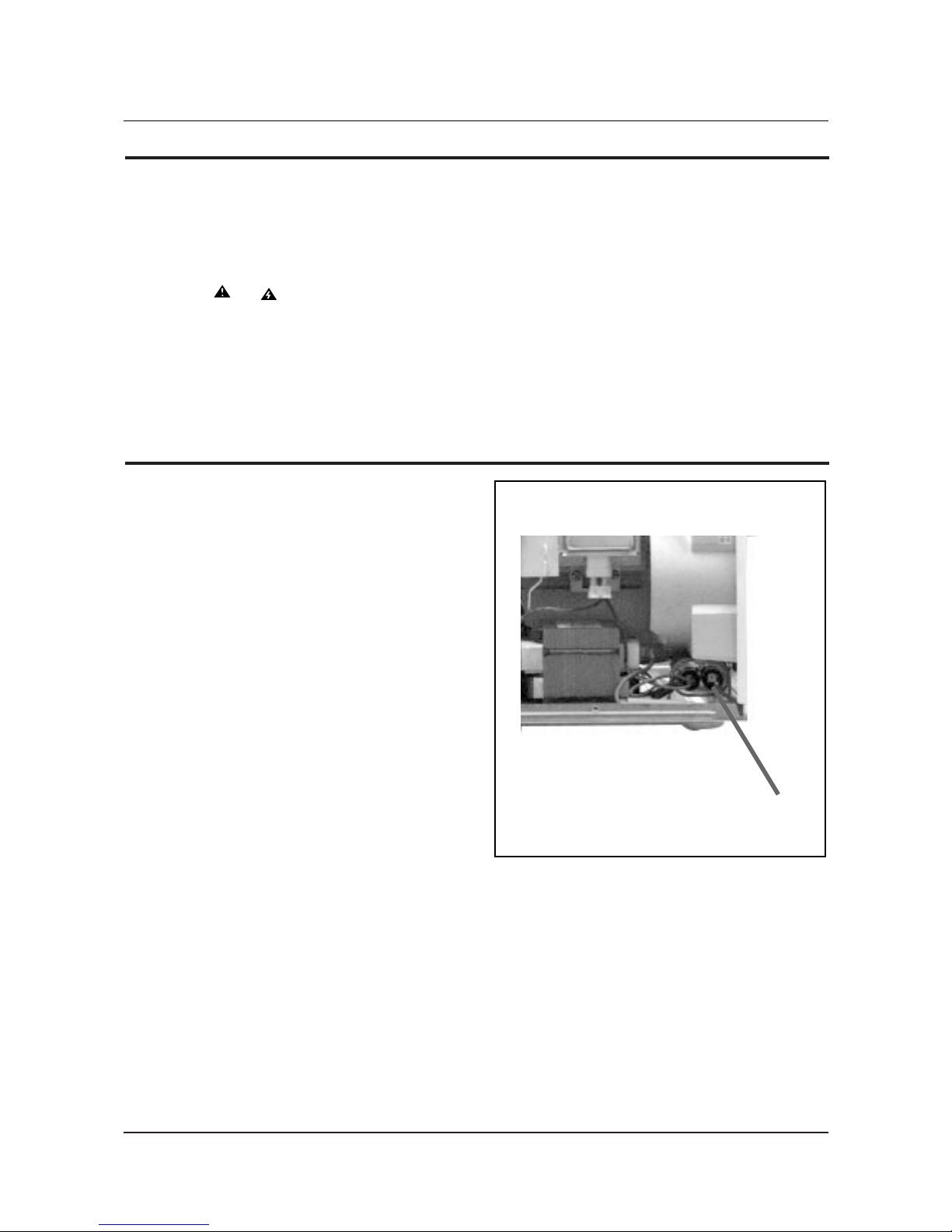
1. High Voltage Warning
Do not attempt to measureany of the high
voltages--this includes the filament voltage
of the magnetron. High voltage is present
during any cook cycle.
Before touching any components or wiring,
always unplug the oven and discharge the
high voltage capacitor (See Figure 1-1)
2. The high-voltage capacitor remains charged
about 30 seconds after disconnection. Short
the negative terminal of the high-voltage
capacitor to to the oven chassis. (Use a
screwdriver.)
3. High voltage is maintained within specified
limits by close-tolerance, safety-related
components and adjustments. If the high
voltage exceeds the specified limits, check
each of the special components.
1-2
Pretaution
1-2 Special Servicing Precautions (Continued)
1-3 Special High Voltage Precautions
Fig. 1-1. Discharging the High Voltage Capacitor
2. Specifications
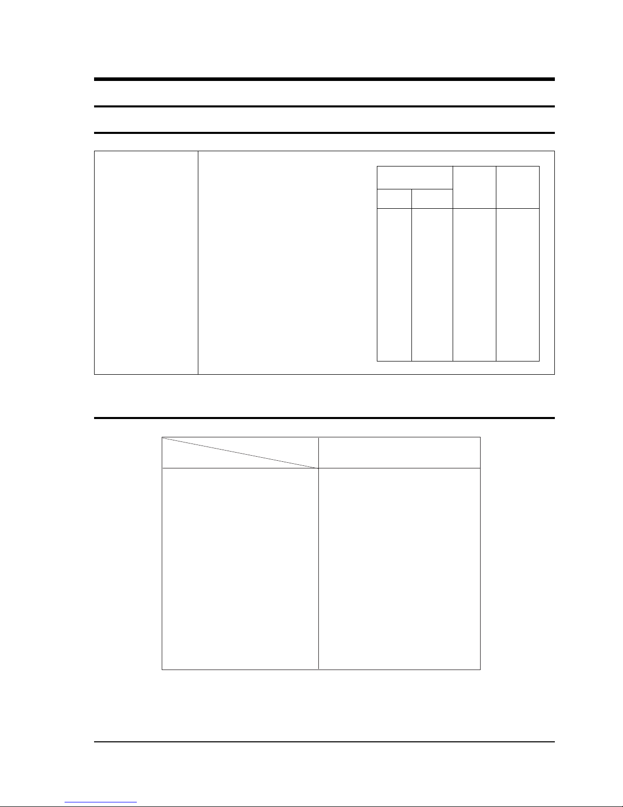
2-1 Table of Specifications
2-1
TIMER 99 MINUTES 90 SECONDS
POWER SOURCE 230V 50Hz, AC
POWER CONSUMPTION MICROWAVE : 1,300W
OUTPUT POWER FROM 80 TO 800W (10 LEVEL POWER)
(IEC-705 TEST PROCEDURE)
OPERATING FREQUENCY 2,450MHz
MAGNETRON OM75SH(31)
COOLING METHOD COOLING FAN MOTOR
OUTSIDE DIMENSIONS 489(W) x 275(H) x 356(D)
POWER LEVEL
% KM2901T
10% 80W 4 sec 26 sec
20% 160W 7 sec 23 sec
30% 240W 10 sec 20 sec
40% 320W 13 sec 17 sec
50% 400W 16 sec 14 sec
60% 480W 19 sec 11 sec
70% 560W 22 sec 8 sec
80% 640W 25 sec 5 sec
90% 720W 28 sec 2 sec
100% 800W 30 sec 0 sec
ON TIME OFF TIME
2-2 Comparison Chart
MODEL
FEATURE
MORE/LESS −
AUTO COOK/DISH −
AUTO DEFROST O
TIME COOK O
POWER LEVEL O
INSTANT COOK O
MEMORY −
BOOST O
CHILD LOCK −
CLOCK O
GRILL −
COMBI −
KM2901T
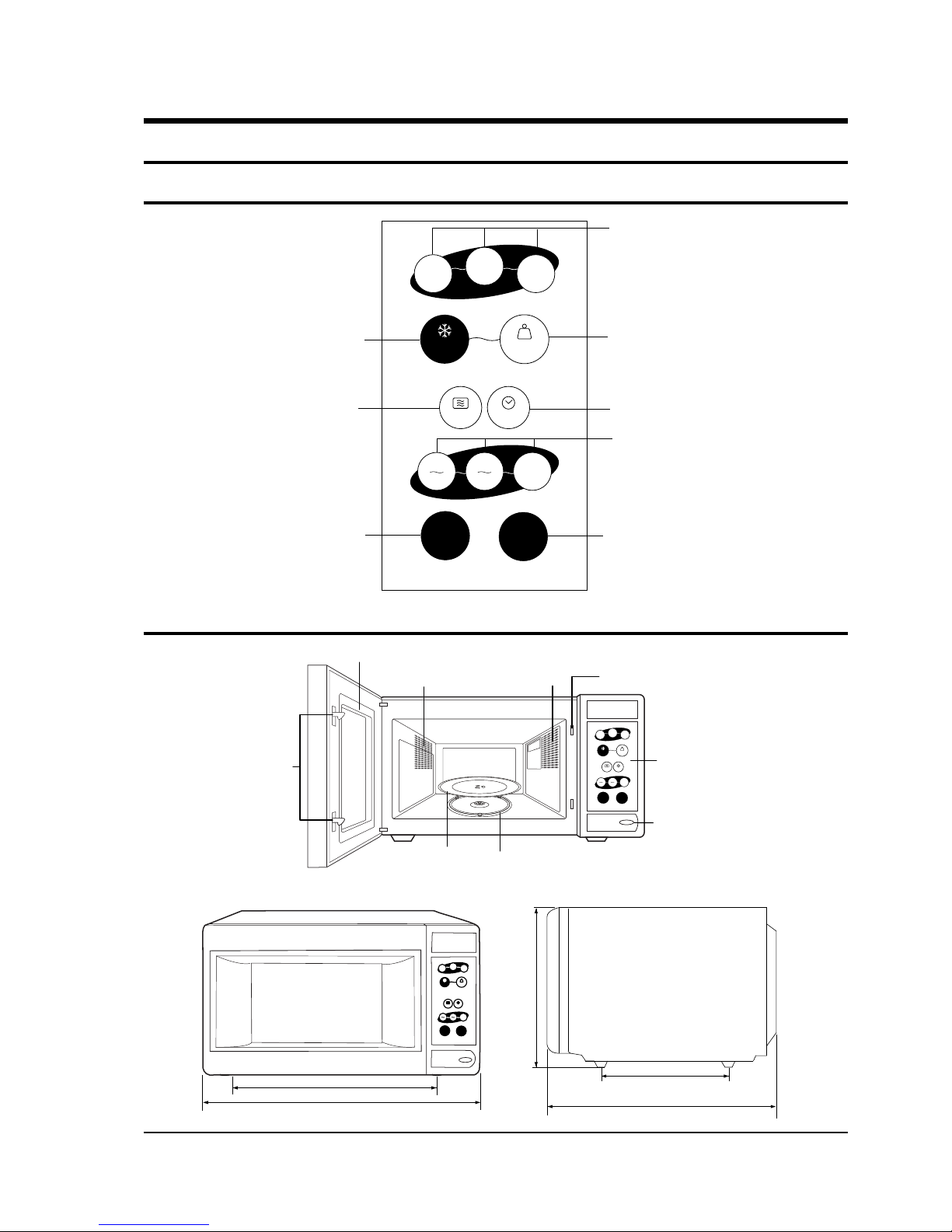
Auto Deforst Button
Power Level Selection Button
Cancel Button
Standard Boost Button
Timer Setting Button
Clock Setting Button
Weight EnteringButton
Instant Cook Button
plated
meal
auto weight
defrost
soup
hot
drink
min.
1min.
10sec.
hr.
10min.
power clock
KM2901T
0.1kg
0.1 kg
start
1min.+
stop
cancel
3. Operating Instructions
3-1 Control Panel
3-1
3-2 Features & External Views
Door
Ventilation Holes
Light
Safety Interlock Holes
Open Door Push Button
Guide Roller
Glass Plate
Door Latches
plated
meal
auto weight
defrost
soup
hot
drink
min.
1min.
10sec.
hr.
10min.
power clock
KM2901T
0.1kg
0.1 kg
start
1min.+
stop
cancel
Control Panel
489mm
357mm
275mm
200mm
356mm
plated
meal
auto weight
defrost
soup
hot
drink
min.
1min.
10sec.
hr.
10min.
power clock
KM2901T
0.1kg
0.1 kg
start
1min.+
stop
cancel
4. Disassembly and Reassembly
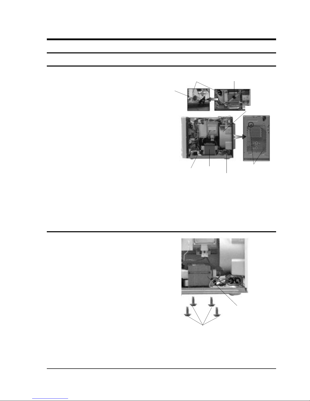
4-1 Replacement of Magnetron, Motor Assembly and Lamp
4-1
Remove the magnetron including the shield case,
permanent magnet, choke coils and capacitors (all
of which are contained in one assembly).
1. Disconnect all lead wires from the magnetron
and lamp.
2. Remove a screw securing the magnetron
supporter.
3. Remove the magnetron supporter.
4. Remove the air cover.
5. Remove screws securing the magnetron to the
wave guide.
6. Take out the magnetron very carefully.
7. Remove screws from the back panel.
8. Take out the fan motor.
9. Remove the oven lamp by rotating to pull out
from hole of air cover.
NOTE1: When removing the magnetron, make
sure that its antenna does not hit any
adjacent parts, or it may be damaged.
NOTE2: When replacing the magnetron, be sure
to remount the magnetron gasket in
the correct position and make sure the
gasket is in good condition.
1. Discharge the high voltage capacitor.
2. Disconnect all the leads.
3. Remove the mounting bolts.
4. Reconnect the leads correctly and firmly.
4-2 Replacement of High Voltage Transformer
Lamp
Magnetron
H. V. Trans
H. V. Capacitor
Screw
Thermo S/WCover Air
Fan Motor
H. V. Trans
Screws
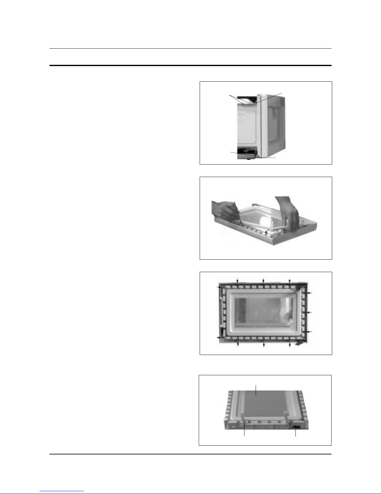
4-3 Replacement of Door Assembly
4-3-1 Removal of Door Assembly
4-2
Remove hex bolts securing the upper hinge and
lower hinge. Then remove the door assembly.
Insert flat screwdriver into the gap between Door
"E" and Door "C" to remove Door "C". Be careful
when handling Door "C" because it is fragile.
Following the procedure as shown in the figure,
insert and bend a thin metal plate between Door
"E" and Door "A" until you hear the 'tick' sound.
1. Insertion depth of the thin metal plate should be
0.5mm or less.
4-3-4 Removal of Key Door & Spring
Remove pin hinge from Door "E"
Detach spring from Door "E" and key door.
4-3-2 Removal of Door "C"
4-3-3 Removal of Door "E"
Disassembly and Reassembly
Upper Hinge
Lower Hinge
Screws
Screws
Key Door Spring
Door "E"
 Loading...