

Kenwood KD-CX-8529 Service Manual
CD RECEIVER
KDC-MP828
KDC-W7531/Y
KDC-W8531/Y
KDC-X789/X8529/X889
SERVICE MANUAL
© 2005-3 PRINTED IN JAPAN
B53-0265-00 (N) 1708
A unique identification number (Unique ID) is given to each unit, which is imprinted on
the CD mechanism assembly. If and when the mechanism assembly or Flash ROM
(IC17) on the mechanism board is replaced, it is necessary to write the Unique ID.
For details, refer to “How to Write the Unique ID” on Page 18.
KDC-MP828
ATT
RDM
VOLVOL
AUDAUD
AME
AUTO
MENU
SCANS.MODE
REP
D
.RDM
KDC-MP828
SCRL
F.
SWSW
M.RDM
AN
PTY/C.S.
SRC
FFFF
ATT
VOLVOL
AUDAUD
KDC-W8531/Y
KDC-W8531
24Bit DAC
ATT
VOL
AUD
System
AMETIMENU
RDM
SCAN
D
S
.MODE
.RDM
F.
REP
M.RDM
SCRL
AN
PTY
SW
SRC
FFFF
ATT
VOLVOL
AUDAUD
KDC-X8529
KDC-X8529
24Bit DAC
ATT
VOL
AUD
System
AUTO
AME
MENU
S
.MODE
RDM
SCAN
D
.RDM
F.
REP
M.RDM
SCRL
AN
SW
SRC
FFFF
ATT
VOLVOL
AUDAUD
KDC-W7531/Y
System
AME MENU
KDC-X789
AME
AUTO
MENU
KDC-X889
AME MENU
AUTO
System
CD MECHANISM EXTENSION
CORD (24P) : W05-0934-00
24Bit DAC
KDC-W7531
RDM
SCAN
D
S
.MODE
S
.MODE
S
.MODE
.RDM
RDM
SCAN
D
.RDM
RDM
SCAN
D
.RDM
F.
REP
REP
REP
24Bit DAC
24Bit DAC
M.RDM
KDC-X789
F.
M.RDM
KDC-X889
F.
M.RDM
SCRL
AN
PTY
SWSW
SRC
FFFF
SCRL
AN
PTY/C.S.
SW
SRC
FFFF
SCRL
AN
PTY/C.S.
SWSW
SRC
FFFF
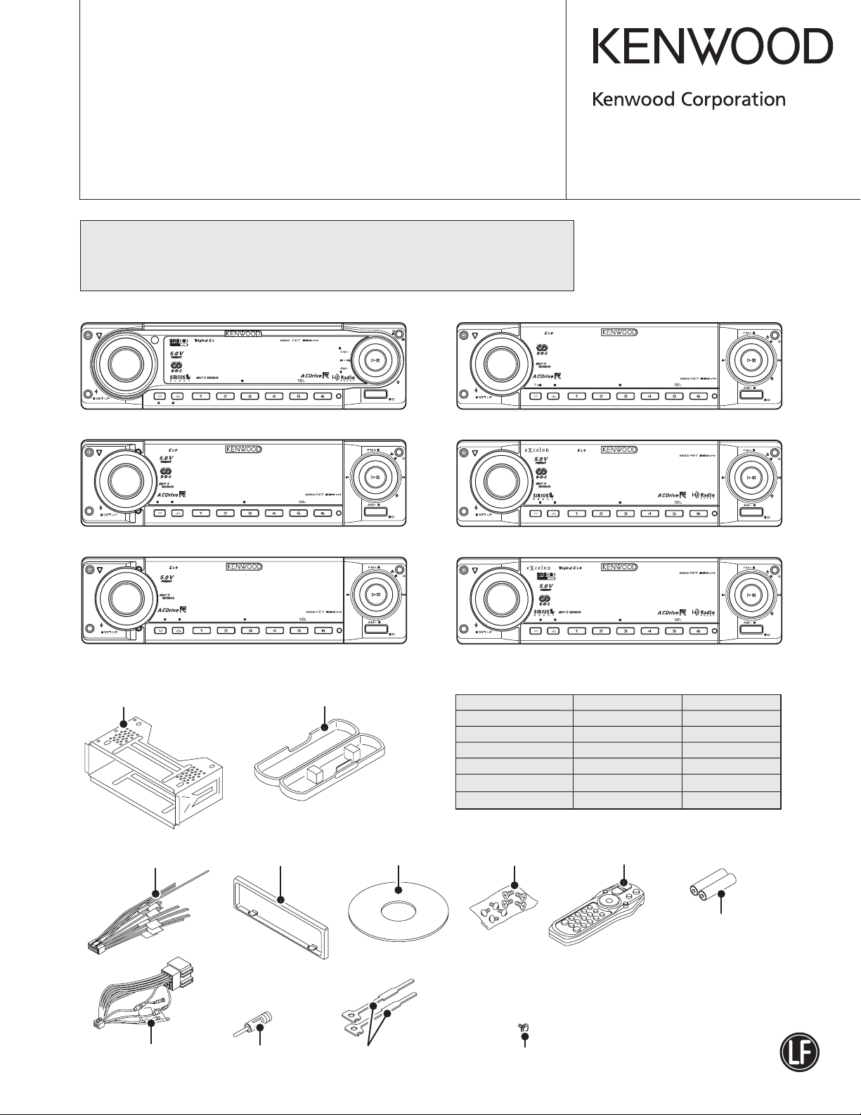
Mounting hardware assy
(J21-9716-03)
* DC cord
(E30-xxxx-xx)
* DC cord
(E30-6412-05)
Plastic cabinet assy
(A02-2732-03)
* Escutcheon
(B07-xxxx-xx)
* Antenna adaptor
(T90-0523-05)
* Compact disc
(W01-xxxx-xx)
Lever
(D10-4589-04) x2
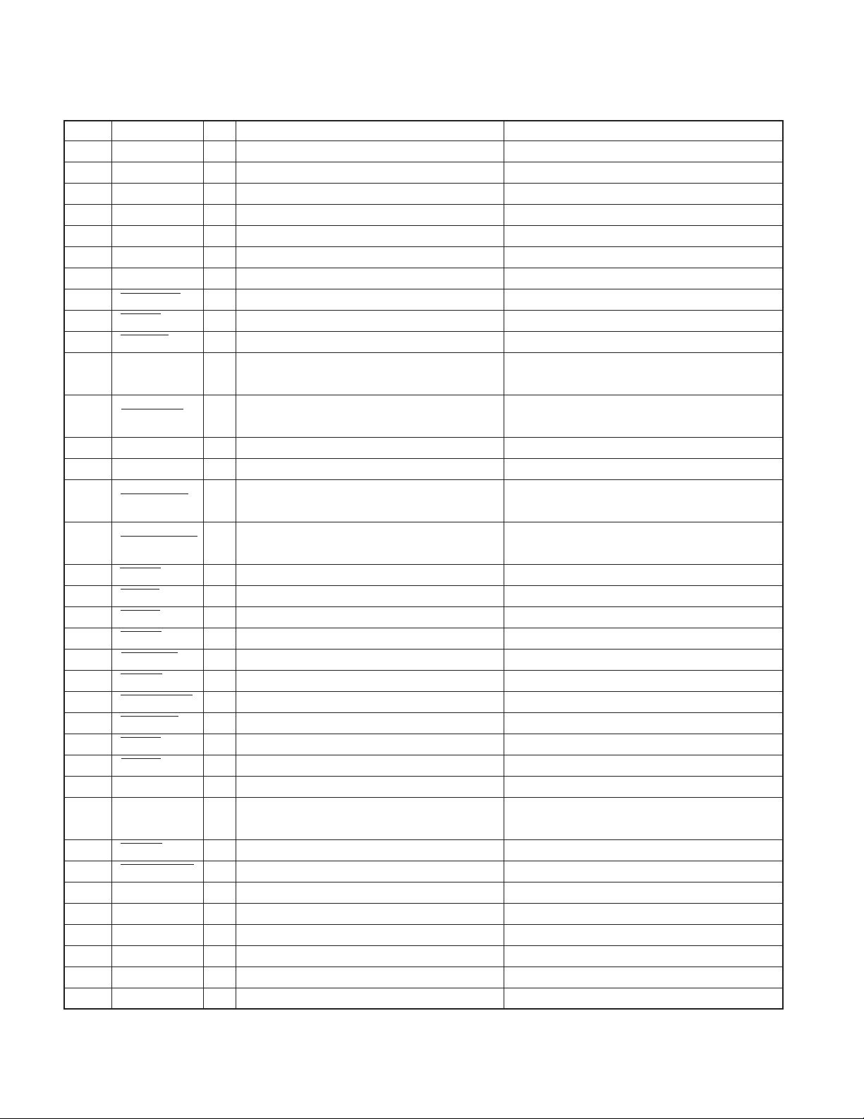
SPARE TDF PANEL
MAIN UNIT NAME TDF PARTS No. TDF NAME
KDC-MP828 Y33-2200-61 TDF-MP85D
KDC-W7531/Y Y33-2190-64 TDF-W7531
KDC-W8531/Y Y33-2190-63 TDF-W8531
KDC-X789 Y33-2190-61 TDF-75DX
KDC-X8529 Y33-2190-62 TDF-X8529
KDC-X889 Y33-2190-60 TDF-85DX
* Screw set
(N99-xxxx-xx)
* Remote controller assy (RC-527)
(A70-2067-05)
Battery
(Not supplied)
* Depends on the model. Refer to the parts list.
* Tapping screw
(N09-xxxx-xx)
This product uses Lead Free solder.
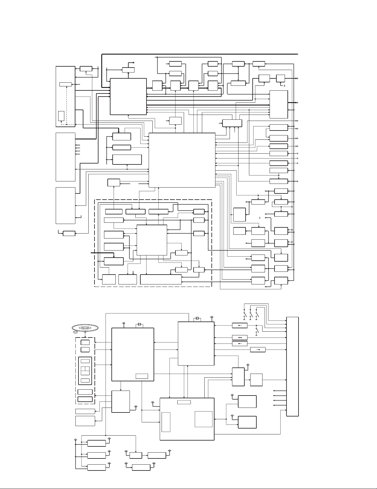
KDC-MP828/W7531/W7531Y/W8531
/W8531Y/X789/X8529/X889
BLOCK DIAGRAM
A1
FRONT-END
E2PROM
FST
CN550
CD/MD
J2
LX-BUS
BU5V
Q450
Q40,
42,45
9V
AUX IN
PRE OUT
(FRONT)
PRE OUT
(REAR)
PRE OUT
(SW)
SP OUT(FL)
SP OUT(FR)
SP OUT(RL)
SP OUT(RR)
WIRED
REMOTE
OPEL DISP
P CON
ANT CON
EXT.AMP.CON
DIMMER
LINE
ACC
BACK UP
A8V
SPECTRUM
IC500
ANALYZER
AGC
WININ OFFSET
MUTE 0,1
MUTE A,C
BU5V
MPX
RDS
Q402,403
A8V
AM+B
SW5V
for
BU5V
A8V
SERVO
D5V
A8V
SW5V
IC300
IC400
IC100
RESET
IC
AUX
FM/AM
CDorMD
CH
(X16-252)
IC104
E-VOL/
SOURCE SELECTOR
RDS
DECODER
MD-DET
INSTALLER
MEMORY
ROM CORRECTION
PANEL
BACK
UP
IC5
RESET SW
IC7
LEVEL SHIFT
KEY MATRIX
DSI
SPECTRUM
ANALYZER
IC1
FLASH ROM
S1
ROTARY
ENCODER
IC2
SPECTRUM
ANALYZER
IC6
Q3-5
ILL+B
REMOTE KEY ILLUMI
IC8
LEVEL SHIFT
IC4
PANEL
u-COM
ED1
IC5 IC3
D3.3V D5VBU5V
IC1
A3.3V A5V
IC4
IC303IC301,302 IC306-308IC305
LPF DSP DAC LPF
IC304
LEVEL
D3.3V
SHIFT
IC102
RST
0,1,2
STBY
MUTE
MUTE A,C
SYSTEM u-COM
Q7,8
SW5V
IC11
D3.3V
IC10
D2.5V
Q6
SW3.3V
Q9,10
FL3.3V
FL+B
Q11,13
FL
BU5V
IC800 Q800,802
A3.3V REF+B
Q801
SVR REF
IC103
MUTE
DRIVER
RST
SW5V
Q100,101
PANEL
OPEN/
CLOSE
DET
M1
PANEL
MECHA
SERVO
D5V
Q22,23
IC450
Q31,33
Q63,64
IC60
IC80
MOTOR
DRIVER
SERVO
DC/DC
(VFD)
Q608-613
PRE
MUTE AMP
IC200
Q206
Q207
Q202
Q203,204
Q205
BU5V
SW5V
A8V
9V
CD5V
FL DC
IC601-603
OP
IC750
POWER
IC
P-CON
Q208,209
ANT-CON
EXT AMP
DIMMER
ACC DET
SURGE DET
B.U DET
Q20,21
BU5V
Q12
SW14V
IC10
A8V
IC601-603
DC/DC
(5VPRE)
Q30,32
MOTOR
+B
PANEL
5V
Q50-52
SW16V
Q41,43,44
ILL+B
ILL+B
CD PLAYER UNIT (X32-5730)
POWER ON
SCK
RESET
IC1
A0
SI
STB
SW3.3V(712)
IC2
16.898MHz
LD
PD
RF AMP
SERVO DSP
SO
INTQ
E
AB
C
F
TR COIL
FO COIL
IC4
MOTOR
DRIVER
S7.5V
SP MOTOR
LOADING &
SLED
MOTOR
POWER ON
D5V
IC5
3.3V REG.
IC21
3.3V REG.
IC20 IC19
2
1.8V REG.
SW3.3V
(712)
SW3.3V
(CS7410)
SW1.8V
(CS7410)
A8V
SW
BU5V
3.3V REG.
EMPH
I2S
RESET
CD I/F
CLK
DI PCM DATA
DOCS
SREQ BREQ
SER/GPIO
ACD DECODER
MP3/WMA/AAC
DECODER
SW5V
C16M
DATA
LRCK
BCLK
FLAG
SW3.3V
(CS7410)
&
SW1.8V
IC14
5V REG.
DATA MUTE
IC15
BU3.3V
26.88MHz
u-COM
DAC RST
DAC MUTE
MEMORY
CONTROLLER
BU3.3V
INFINITY 0 DET.L/R
DAC CONTROL
PCM LRCK
PCM BCLK
PCM XCK
ROM
8BIT
0-2MB
DRAM
4,8,16BIT
256k-8MB
IC18
SW3.3V
(CS7410)
SW3.3V
(CS7410)
3.3 5V
3.3 5V
3.3 5V
SW3.3V(712)
DAC
IC17
IC16
2x512kx16BIT
SW5V
FLASH
ROM
4MBIT
512kx8BIT
SDRAM
16MBIT
3.3 5V
IC13
LPF
LOS-SW
12EJE-SW
8EJE-SW
LOE/LIM SW
MSTOP,MRESET
AUDIO MUTE
L/R
L/R
BU5V
A8V
D5V
S7.5V
I2C
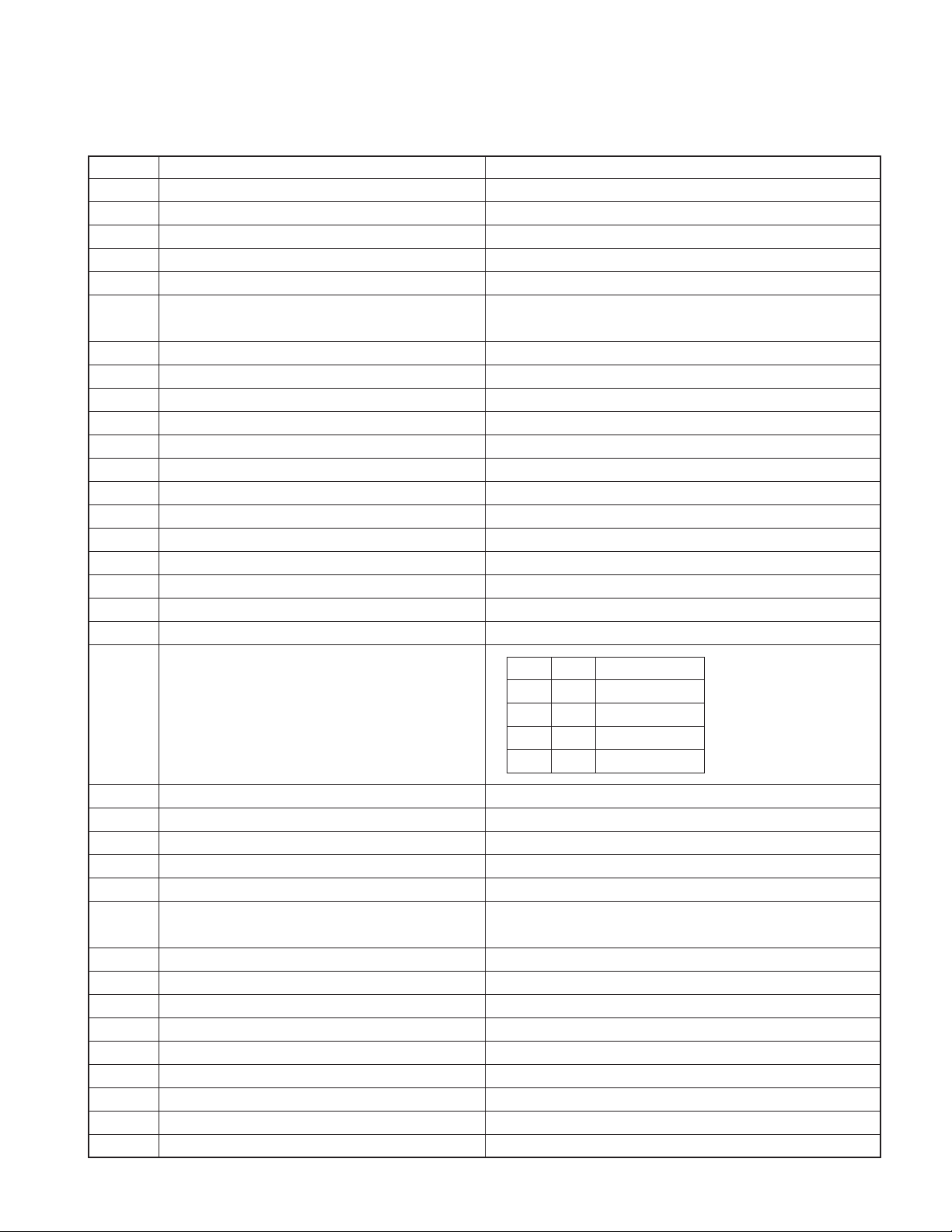
KDC-MP828/W7531/W7531Y/W8531
/W8531Y/X789/X8529/X889
COMPONENTS DESCRIPTION
● ELECTRIC UNIT (X34-3xxx-xx)
Ref. No. Application / Function Operation / Condition
IC1 DSP ANALOG POWER SUPPLY 3.3V output
IC3 DAC DIGITAL POWER SUPPLY 5.0V output
IC4 DAC ANALOG POWER SUPPLY 5.0V output
IC5 DSP DIGITAL POWER SUPPLY 3.3V output
IC10 AUDIO8V REF POWER SUPPLY 1.27V output
IC60 SWITCHING REGULATOR CONTROLLER
IC80 FL+B VFD power supply (57V)
IC100 RESET IC "L" when detection voltage is 3.6V or less
IC102 SYSTEM µ-COM
IC103 MUTE DRIVER Mute control
IC104 E2PROM Installer memory
IC200 POWER CONTROL IC Power control switching
IC300 E-VOL & SOURCE SELECTOR Source / Volume / Tone control
IC301,302 AUDIO BUFFER AMP DSP input LPF
IC303 DSP Digital signal processing
IC304 LEVEL SHIFT Conversion from 3.3V to 5.0V
IC305 DAC D/A Converter
IC306~308
IC400 RDS DECODER
AUDIO BUFFER AMP DAC output LPF
VFD / Mechanism digital power supply.
OUT1 : VFD (4.7V), OUT2 : Mechanism digital (5V)
FM/AM tuner / Changer / CD mechanism / Panel / Volume / Tone control
IN1 IN2 PANEL MECHA
LLWAIT
IC450 PANEL MECHA MOTOR DRIVER
IC451 G-ANALYZER Analog gravity sensor
IC500 SPECTRUM ANALYZER BUFFER AMP & AGC Spectrum analyzer buffer / Auto gain control
IC600 ±9V AVR 5V pre-out power supply
IC601~603
IC750 POWER IC Front L/R and a rear L/R signal amplification
IC800 AUDIO3.3V REF SUPPLY / SVR6.8V REF SUPPLY
Q10,11 AUDIO8V AVR When Q11 base is “H”, A8V is output
Q12 SW14V When base is “H”, SW14V is output
Q20,21 B.U.5V AVR When backup is “ON”, BU5V is output
Q22,23 SW5V When Q23 base is “H”, SW5V is output
Q30,32 MOTOR+B AVR (PANEL MECHA) When Q9 base is “H”, 7.5V MOTOR+B is output
Q31,33 SERVO+B AVR When Q33 base is “H”, 8V SERVO+B is output
Q40,42,45 PANEL5V AVR When Q42 base is “H”, PANEL5V is output
Q41,43,44 ILLUMINATION AVR When Q43 base is “H”, 10.5V ILLUMI voltage is output
Q50~52 SW16W (SERGE PROTECTION) When Q51 base is “H”, SW16V (13V) is output
5V PREOUT AMP Buffer/Gained control
LHOPEN
HLCLOSE
HHSTOP
Supplying audio 3.3V reference voltage to E-VOL/LPF
Supplying SVR6.8V reference voltage to IC750 (POWER IC)
3
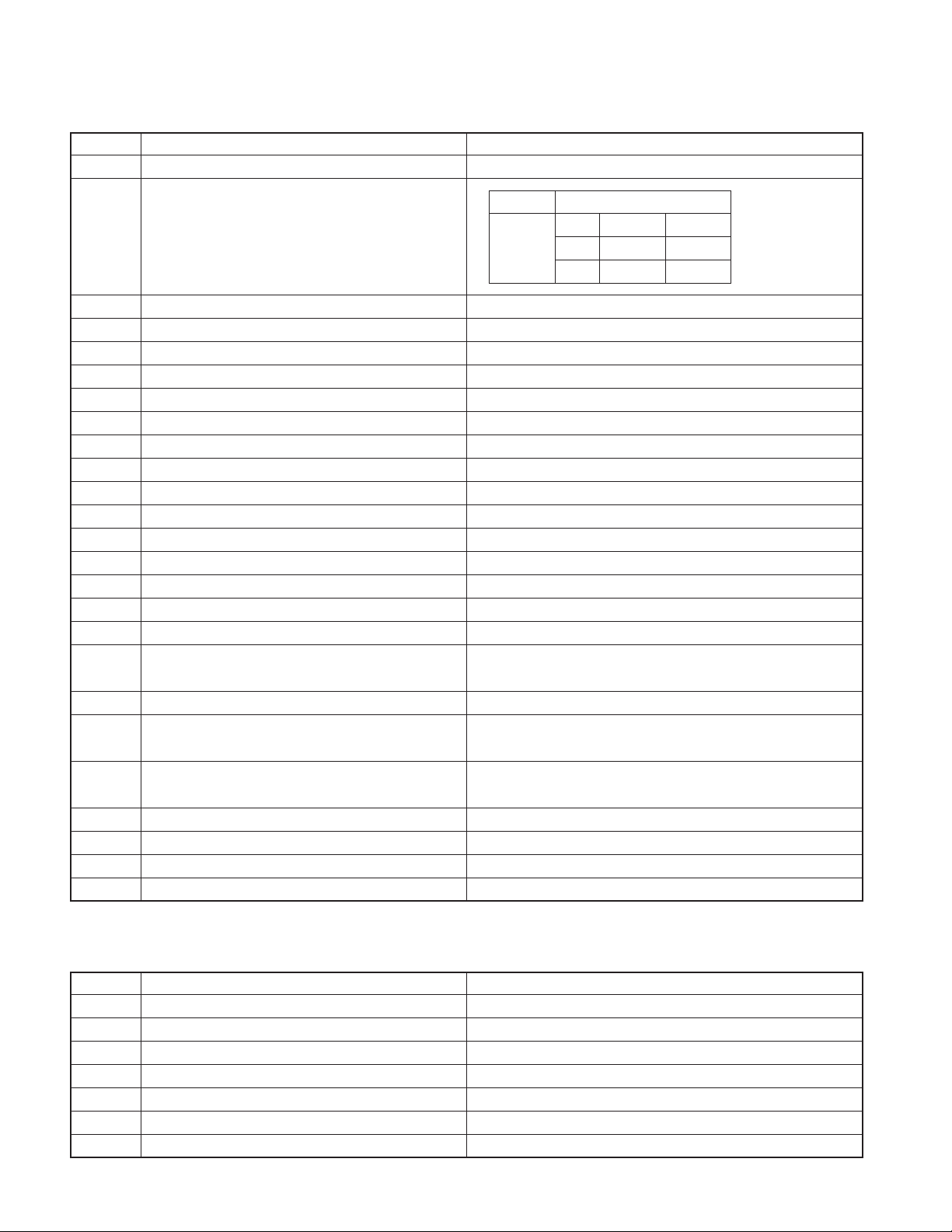
KDC-MP828/W7531/W7531Y/W8531
/W8531Y/X789/X8529/X889
COMPONENTS DESCRIPTION
Ref. No. Application / Function Operation / Condition
Q60 VFD (4.7V) AVR SW When base is “H”, VFD AVR is turned “OFF”
F SEL2 (BASE)
Q61
Q62 MECHA DIGITAL AVR SW When base is “H”, MECHA DIGITAL AVR is turned “OFF”
Q63 VFD (4.7V) AVR SWITCHING POWER DRIVER Controlled by IC60 and Q61 determines frequency
Q64 MECHA DIGITAL AVR POWER DRIVER Controlled by IC60 (Frequency is fixed to 400kHz)
Q80,81 VFD (57V) AVR SW When Q81 base is “H”, VFD (57V) is output
Q91 PANEL5V DISCHARGE SW When base is “H”, PANEL5V is discharged
Q100,101 PANEL DETECT SW When Q100 base is “L”, panel is detected
Q200,201 PREOUT MUTE DRIVER When base is “L”, MUTE DRIVER is turned “ON”
Q202 ACC DETECT SW When base is “H”, ACC voltage is detected
Q203,204 SERGE DETECT SW When Q204 base is “H”, IC750 (POWER IC) is turned to standby.
Q205 BU DETECT SW When Q35 base is “H”, backup voltage is detected
Q206 EXT AMP CONTROL BUFFER Output buffer from IC102 (µ-COM)
Q207 SMALL LAMP DETECT SW When base is “H”, small lamp is detected
Q208,209 POWER ANTENNA SW Q206 base is “H”, 14V POWER ANTENNA voltage is output
Q300 DSP MUTE SW When base is “L”, DSP is muted
Q402,403 AM+B SW When Q403 base is “H”, AM+B is output
Q450 DSI DRIVER
Q500 SPECTRUM ANALYZER AGC CONTROLLER
Q600~602
Q603~605
Q606,607 AUDIO 10.5V AVR When Q606 base is “H”, 10.5V is output
Q608~613
Q800,802 REF+B AVR When Q800 base is “H”, 13V is output
Q801 SVR6.8V REF SUPPLY AGC CONTROLLER
SWITCHING REGULATOR FREQUENCY
CONTROL SW (IC60)
PRE-AMP +9V AVR
PRE-AMP -9V AVR
PREOUT MUTE SW When base is “H”, pre-out is muted
F SEL1
(BASE)
When base is “H”, DSI is turned “ON”. When base is “L”, DSI is
turned “OFF”. When panel is off, DSI blinks.
When excess input is made, feed-back is interrupted which slows down output.
Q600 and Q602 function as differential amplifier.
Q601 functions as a driver and +9.4V is supplied to op amp for pre-out.
Q603 and Q605 function as differential amplifier.
Q604 functions as a driver and –9.1V is supplied to op amp for pre-out.
When backup voltage is down, feed-back is interrupted which slows down output.
L 400kHz 600kHz
H 650kHz 850kHz
LH
● SWITCH UNIT (X16-2950-1x / X16-3122-71)
Ref. No. Application / Function Operation / Condition
IC1 ROM IC / FLASH ROM IC Display image data storage
IC2 SPECTRUM ANALYZER 6-ch band pass filter
IC4 PANEL µ-COM
IC5 RESET IC Functions when panel is attached
IC6 REMOTE CONTROL
IC7 LEVEL SHIFT Conversion from 5V level to 3.3V
IC8 LEVEL SHIFT Conversion from 3.3V level to 5V
4
KDC-MP828/W7531/W7531Y/W8531
/W8531Y/X789/X8529/X889
COMPONENTS DESCRIPTION
Ref. No. Application / Function Operation / Condition
IC9 BUFFER Functions when controlling fruorescent indicator tube (ED1)
IC10 2.5V REGULATOR For 2.5V power supply
IC11 3.3V REGULATOR For 3.3V power supply
Q1 TRIANGLE GREEN LED SW Lights up when base is “H”
Q2 TRIANGLE RED LED SW Lights up when base is “H”
Q3 BLUE LED SW Lights up when base is “H”
Q4 GREEN LED SW Lights up when base is “H”
Q5 RED LED SW Lights up when base is “H”
Q6 SW3.3V SW When base is “L”, SW3.3V is supplied to IC1 and IC3
Q7,8 SW5V SW When Q8 base is “H”, SW5V is supplied to IC2 and IC6
Q9,10 FL3.3V SW
Q12 FL BLK SW When base is “H”, fruorescent indicator tube (ED1) lights up
Q11,13 FL+B SW
When Q9 base is “H”, FL+3.3V (VDD1) is supplied to fruorescent indicator tube
When Q11 base is “H”, FL+B (VDD2) is supplied to fruorescent indicator tube
● CD PLAYER UNIT (X32-5730-00)
Ref. No. Application / Function Operation / Condition
IC1 µ-com for mechanism control
IC2 LSI for CD signal processing +RF AMP
IC4 BTL driver SP, SL (including LO/EJ) motor and PU actuator
IC5 SW3.3V regulator 3.3V power supply for IC2, PU, and IC18 digital section
IC13 Audio active filter Secondary LPF
IC14 A5V regulator 5V power supply for DAC
IC15 Compacted audio decoding DSP AC drive decoder, MP3/WMA/AAC decoder
IC16 Compacted audio expanding SDRAM
IC17 Decoder software, unique ID storage flash ROM
IC18 Audio external 24-bit D-A converter
IC19 BU3.3V regulator 3.3V power supply for µ-com
IC20 1.8V regulator 1.8V power supply for core section of IC15
IC21 Decoder/SDRAM/Flash ROM 3.3V regulator 3.3V power supply for port section of IC15, IC16 and IC17
Q1,4 Level shift (3.3V~5V) FET
Q3,5,6 Level shift (3.3V~5V) transistor with 2 elements
Q7 Level shift (3.3V~5V) transistor
Q8 APC (Auto Power Control) transistor
Q9,10
Q11 A5V power supply constant circuit FET
Q12,13 SW8V SW transistor
Q14,15 SDRAM 3.3V power supply SW transistor SDRAM power supply is turned off when /CSRST is “L”
D2
D3 Protection diode for pick-up laser diode
D4,D5 Diode for securing audio L-R reference voltage
D6
Tr ansistor for preceding beam delaying SW during non-search
UPD63712GC built-in resetting terminal static protection diode
Diode for control terminal’s “L” confirmation for IC20 and IC21
5

KDC-MP828/W7531/W7531Y/W8531
/W8531Y/X789/X8529/X889
MICROCOMPUTER’S TERMINAL DESCRIPTION
● SYSTEM MICROCOMPUTER : IC102 (X34- : ELECTRIC UNIT)
Pin No. Pin Name I/O Function Processing Operation
1 VREF - Analog reference voltage
2AVCC -
3 LX DATA S I Data from slave unit
4 LX DATA M O Data to slave unit
5 LX CLK I/O LX-BUS clock
6 WIRED REMO I External display remoter controller
7 LX MUTE I Mute request from slave unit H : MUTE ON, L : MUTE OFF
8AUD SDA O E-VOL data SPI communication
9AUD SEL O E-VOL control SPI communication
10 AUD SCL O E-VOL clock SPI communication
11 DAC RST O DAC reset L : DAC RESET
12 NC - Not used
13 BYTE - GND
14 CNVSS -
15 XCIN I Clock 32,768kHz
16 XCOUT I Clock 32,768kHz
17 RESET I Reset
18 XOUT - Clock 12MHz
19 VSS - GND
20 XIN - Clock 12MHz
21 VCC1 -
22 NMI I
23 PANEL DET I Panel detection H : No panel, L : Panel exists
24 RDS CLK I RDS decoder clock
25 LX REQ S I Communication request from slave unit
26 PON AM I/O AM power supply control AM in operation : H, AM not in operation : HI-Z
27 LX REQ M O Communication request to slave unit
28 TUN IFC OUT I Front-end IFC out H : Station exists, L : No station
29 RDS AFS L I/O Time constant switching when noise detected Refer to Truth Value Table (RDS AFS)
30 RDS AFS M I/O Time constant switching when noise detected Refer to Truth Value Table (RDS AFS)
31 RDS QUAL I RDS decoder QUAL
32 RDS DATA I RDS decoder DATA
33 PWIC BEEP O Beep
34 TUN SCL I/O Front-end I2C clock MAX 400kHz
35 TUN SDA I/O Front-end I2C data
36 SYS DATA O Inside-panel communication data MAX 500kbps
37 VCC1 -
38 PAN DATA I Inside-panel communication data MAX 500kbps
39 VSS -
40 SYS REQ O Communication request from system µ-com
41 PAN REQ I Communication request from panel
42 SDA I/O E2PROM I2C data MAX 100kHz
6
KDC-MP828/W7531/W7531Y/W8531
/W8531Y/X789/X8529/X889
MICROCOMPUTER’S TERMINAL DESCRIPTION
Pin No. Pin Name I/O Function Processing Operation
43 SCL I/O E2PROM I2C clock MAX 100kHz
44 PON PANEL I/O Panel 5V control
45 DSI I/O DSI control
46~49 NC - Not used.
50 PM MOT1 O Panel motor control 1 Refer to Truth Value Table (PANEL MOTOR)
51 PM MOT2 O Panel motor control 2 Refer to Truth Value Table (PANEL MOTOR)
52 EPM I Flash EPM
53 PM OPEN I Panel full open detection Refer to Truth Value Table (PANEL MECHA)
54~56 NC - Not used
57 P5V DIS I/O Panel 5V discharge control H : Discharge, Other : Hi-Z
58 PM CLOSE I Panel mechanism close detection Refer to Truth Value Table (PANEL MECHA)
59 ROMCOR DET I E2PROM write request H : Write
60 PM DET I Panel mechanism detection H : Function check in progress
61 SC CON O
62 NC - Not used
63 TUN TYPE1 I Destination setting 1 TUN TYPE1 : L, TUN TYPE2 : L
64 TUN TYPE2 I Destination setting 2 TUN TYPE1 : L, TUN TYPE2 : L
65,66 NC - Not used
67
68 CD LOS SW I CD loading detection
69 CD MUTE R I CD mute (Rch) request L : Rch mute request
70 CD MUTE L I CD mute (Lch) request L : Lch mute request
71 CD MRST O CD mechanism microcomputer reset L : Reset, H : Normal
72 CD MSTOP O CD mechanism microcomputer stop
73 NC - Not used
74
75 CD LOEJ I/O CD motor control Refer to Truth Value Table (CD MOTOR / CD LOEJ)
76 CD MOTOR O CD motor control Refer to Truth Value Table (CD MOTOR / CD LOEJ)
77 PON ILLUMI I/O Key illumination power supply control ON : H, OFF : Hi-Z
78 PON CD I/O CD/WMA power supply control At time of CD source: H, Other than CD : Hi-Z
79 PON O Power supply control POWER ON : H, POWER OFF : L
80 PON FL+B O
81 PON FDC I/O
82 F SEL1 O SW-Reg frequency switching
83 F SEL2 O SW-Reg frequency switching
84 DIAG I/O P-CON excess current surveillance
85 VCC2 -
86 EXT AMP CON I/O External amplifier control
87 VSS -
88~91
92 NC - Not used
CD DISC12 SW
CD LOE LIM SW
TYPE 1~TYPE4
Inside-panel communication (Chip enable when flash)
I 12cm CD detection
I CD detection (Chucking SW) H : Loading complete, L : No disc
Fruorescent indicator tube bias power supply control
Fruorescent indicator tube filament power supply control
I Destination switching
ON : H (Momentary power down/Panel detached)
11 Minutes after ACC OFF : Hi-Z
POWER OFF, ACC OFF : L
L : Mechanism microcomputer stop,
H : Mechanism microcomputer in operation
POWER ON : H, POWER OFF or display black out : L
POWER ON : L, POWER OFF or display black out : Hi-Z
7
KDC-MP828/W7531/W7531Y/W8531
/W8531Y/X789/X8529/X889
MICROCOMPUTER’S TERMINAL DESCRIPTION
Pin No. Pin Name I/O Function Processing Operation
93
94
95 OEM DISP CE I/O External display control request External display
96 NC - Not used.
97 P CON O External amplifier control POWER ON : H, POWER OFF or STANDBY : L
98 NC - Not used.
99 ANT CONT O Power antenna control TUNER ON : H
100 ILLUMI DET I Dimmer illumination detection L : ON, H : OFF
101 BU DET I Momentary power down detection BU : L, No BU or momentary power down : H
102 ACC DET I ACC power supply detection ACC ON : L, ACC OFF : H
103 (PWIC SVR) O SVR discharge circuit
104 PWIC MUTE O Power IC mute
105 PWIC STBY O Power IC standby control POWER ON : H, POWER OFF : L
106 LX CON O Start up request to slave unit H : SLAVE UNIT ON, L : SLAVE UNIT OFF
107 MUTE PRE R O Rch pre-out mute
108
109 MUTE 0 O E-VOL front mute ON : L, OFF : H
110 MUTE 1 O E-VOL rear mute ON : L, OFF : H
111 MUTE 2 O E-VOL sub mute ON : L, OFF : H
112 MUTE A O E-VOL spctrum analyzer mute ON : L, OFF : H
113 DSP MUTE I/O DSP mute ON : L, OFF : Hi-Z
114 MUTE C O E-VOL AFS mute ON : L, OFF : H
115 DSP INIT RST O DSP initial reset L : Reset, H : Reset release
116 DSP S RST O DSP system reset L : Reset, H : Reset release
117 DSP RQ O Request to DSP L : Request
118 DSP CS O DSP chip select L : Select
119 NC (GTEST) O Not used
120 LINE MUTE I Line mute detect
121 MD DET I For a terminal of MD receiver
122 PWIC DC DET I DC offset error detect
123 LX RST O Hard reset to slave unit H : Reset, L : Normal
124 G Y OUT I Analog Y gravity detect
125 G X OUT I Analog X gravity detect
126 RDS NOISE I FM noise detection
127 AVSS -
128 TUN SMETER I S-meter input
OEM DISP DATA
OEM DISP CLK
CD MUTE PRE L
I/O External display DATA External display
I/O External display CLK External display
H : 5 seconds after POWER OFF and momentary
power down, Then : L
L : When STANDBY source or momentary power
down, L : When TEL MUTE
L : When “MUTE PRE R” is “L” or at momentary
power down, H : Only when 2-zone
O Lch pre-out mute
L : When “MUTE PRE L” is “L” or at momentary power
down, H : Only when 2-zone
TEL MUTE : 1V or less,
NAVI MUTE : 1V or less, 2.5V or more
8
MICROCOMPUTER’S TERMINAL DESCRIPTION
Truth Value Table
CD MOTOR / CD LOEJ
CD MOTOR
Standby L Hi-Z
Eject H H
Load H L
Brake H Hi-Z
Use prohibited
PANEL MOTOR
OPEN CLOSE STOP WAIT
PM MOT1 L H H L
PM MOT2 H L H L
CD LOEJ
LL
KDC-MP828/W7531/W7531Y/W8531
/W8531Y/X789/X8529/X889
PANEL MECHA
FULL OPEN FULL CLOSE OTHER
PM OPEN H L L
PM CLOSE H L H
RDS AFS
RDS AFS M RDS AFS L
AFS LOW L L
AFS MID L Hi-Z Sound output with AF search
AFS HIGH Hi-Z Hi-Z Normal reception
No sound output with AF search
Condition
● PANEL MICROCOMPUTER : IC4 (X16- : SWITCH UNIT)
Pin No. Pin Name I/O Function Processing Operation
1~7 D14~D8 I/O Data input/output
8 3.3VDD - 3.3V
9 VSS - Connect to GND
10~17 D7~D0 I/O Data input/output
18 FLGCP1 O FL harmony control
19 NC - Not used
20 SYS REQ I System µ-com communication request H : Data communication
21 SC CON I
22 FL BK O Fruorescent indicator blackout control H : Fruorescent indicator turned on, L : turned off
23 2.5VDD - 2.5V
24 VSS - Connect to GND
25 NC - Not used
26,27 KS1, KS2 I/O Key scan L : Output, Hi-Z : Switching
28,29 TD0, TD1 - Not used
30,31 KS3, KS4 I/O Key scan L : Output, Hi-Z : Switching
32 TRST - Pull down
33 ROTARY CCW I Rotary A 1-pulse/2-click, 15-pulse/360°
34 ROTARY CW I Rotary B 1-pulse/2-click, 15-pulse/360°
35,36 TMS, TCM - Not used
37 3.3VDD - 3.3V
38 EVSS - Connect to GND
39 KS5 I/O Key scan L : Output, Hi-Z : Switching
40~42 KR1, KR2, KR3 I Key return
43 FLGCP2 O Fruorescent indicator harmony control
44 PAN REQ O Panel communication request H : Data communication in progress
System µ-com communication/Panel operation control
Lighting timing (brightness harmony) is controlled
with pulse interval. GCP=FLGCP1+FLGCP2
H : Panel operation
Lighting timing (brightness harmony) is controlled
with pulse interval. GCP=FLGCP1+FLGCP2
9
KDC-MP828/W7531/W7531Y/W8531
/W8531Y/X789/X8529/X889
MICROCOMPUTER’S TERMINAL DESCRIPTION
Pin No. Pin Name I/O Function Processing Operation
45 SYS DATA I Data reception from system µ-com UART communication 500kbps
46 PAN DATA O Data transmission from panel UART communication 500kbps
47 FL CLK O
48 KR4 INT I Key return Interruption possible
49 FL DATA1 O Fruorescent indicator serial control data
50 CLK IN3 I Serial synchronization clock Synchronized to Fruorescent indicator CLK
51 FL EL O Fruorescent indicator skip shift control H or Hi-Z : Odd number skip, L : Even number skip
52 FL DATA2 O Fruorescent indicator serial control data
53 CLK IN2 I Serial synchronization clock Synchronized to Fruorescent indicator CLK
54 FL LAT O Fruorescent indicator latch control
55 FL DATA3 O Fruorescent indicator serial control data
56 3.3VDD - 3.3V
57,58 X2,X1 I Clock 6.6MHz
59 CVSS - Connect to GND
60 CKSEL - Connect to GND
61 PSEL - Connect to VDD
62 2.5VDD - 2.5V
63 VSS - Connect to GND
64 MODE0 - Connect to GND
65 MODE1 - Pull down
66 PAN RST I Input from reset IC
67 AVDD1 I D/A conversion reference voltage Connect to D3.3V
68,69 NC - Pull down
70,71 AVSS1,AVSS0 - D/A conversion reference GND
72 AVDD0 - A/D conversion reference voltage Connect to D3.3V
73 WAVE IN I Voice input AD read
74 F01 I BPF (63Hz) AD read
75 F02 I BPF (150Hz) AD read
76 F03 I BPF (330Hz) AD read
77 F04 I BPF (1kHz) AD read
78 F05 I BPF (3.3kHz) AD read
79 F06 I BPF (10kHz) AD read
80 NC - Pull down
81 2.5VDD - 2.5V
82 VSS - Connect to GND
83 NC - Not used
84 TYPE I
85
86 REMO I Remote controller signal Detection with pulse width
87 PON FL+B O Fruorescent indicator bias power supply switch H : ON, L : OFF
88 PON FLVDD I/O
89 PON 5V I/O 5V power supply switch
NC (VREFCON)
Fruorescent indicator serial communication reference clock
Whether there is customizing or not designation setting
O Not used
Fruorescent indicator logic section power supply switch
Reference clock 4.125MHz
H : Flash ROM (This model), L : Mask ROM (Other model)
H : ON, Hi-Z : OFF
Remote controller IC / Space analyzer IC power
supply H : ON, Hi-Z : OFF
10
KDC-MP828/W7531/W7531Y/W8531
/W8531Y/X789/X8529/X889
MICROCOMPUTER’S TERMINAL DESCRIPTION
Pin No. Pin Name I/O Function Processing Operation
90~93 NC - Not used
94 WE I/O Memory data write permission L : Write, H : Wait SW3.3V start up : Hi-Z
95 OE I/O Memory data transmission permission
96,97 NC - Not used
98 3.3VDD - 3.3V
99 VSS - Connect to GND
100 FROMCHK - Not used
101 CE I/O Memory operation permission L : Operation, H : Wait SW3.3V start up : Hi-Z
102~104
105 ROMCOR SCL - Not used
106 ROMCOR SDA - Not used
107 NC (SEL E2P) - Not used
108
109 PON TRI RED I/O Triangle red light ON switch H : Light ON, Hi-Z : Light OFF
110 PON BLUE I/O Blue sub-illumination light ON switch H : Light ON, Hi-Z : Light OFF
111 SA RST O Spectrum analyzer IC reset H : Reset (1.8V or higher), L : Normal
112 3.3VDD - 3.3V
113 EVSS - Connect to GND
114 PON GREEN I/O Green key illumination light ON switch H : Light ON, Hi-Z : Light OFF
115 PON RED I/O Red illumination light ON switch H : Light ON, Hi-Z : Light OFF
116 PON SW3V I/O Rotary encoder power supply L : ON, Hi-Z : OFF
117 NC O Not used
118~123
124 2.5VDD - 2.5V
125 VSS - Connect to GND
126~133
134 3.3VDD - 3.3V
135 EVSS - Connect to GND
136~142
143 NC - Not used
144 D15 I/O Data input/output
NC - Not used
PON TRI GREEN
A21~A16 O Address output
A15~A8 O Address output
A7~A1 O Address output
I/O Triangle green light ON switch
L : Data transmission, H : Wait SW3.3V start up : Hi-Z
H : Light ON, Hi-Z : Light OFF, When blackout : Light ON
● MECHANISM MICROCOMPUTER : IC1 (X32- : CD PLAYER UNIT)
Pin No. Pin Name I/O Function Processing Operation
1 VREFL I ADC reference power supply input terminal (L) GND
2 DMUTE O Driver MUTE L : STOP, H : MUTE OFF
3 CSRST O (Decoder) Resetting control L : RESET, H : NORMAL
4NCONot used. Open output L-fixed
5 LZM I 0bit MUTE detection (Lch) L : MUTE OFF, H : MUTE ON
6 RZM I 0bit MUTE detection (Rch) L : MUTE OFF, H : MUTE ON
7 BREQ I (Decoder) BREQ signal input
8 DSPINT I (DSP) interruption signal input H : Interruption
11

KDC-MP828/W7531/W7531Y/W8531
/W8531Y/X789/X8529/X889
MICROCOMPUTER’S TERMINAL DESCRIPTION
Pin No. Pin Name I/O Function Processing Operation
9 SREQ O (Decoder) SREQ signal output
10 NC O Not used. Open output L-fixed
11 S_DATA O (Decoder) Data output for serial data
12 B_DATA I (Decoder) Data input for serial data
13 CLK O (Decoder) Clock output for serial data
14 DSPTXD1 O (DSP) Data output for serial data
15 DSPRXD1 I (DSP) Data input for serial data
16 DSPSCLK1 O (DSP) Clock output for serial data
17 AM0 - ROM mode selection terminal H : NORMAL, L : External ROM mode
18 DVCC - BU3.3V
19 X2 O Oscillator connection 26.88MHz
20 DVSS - GND
21 X1 I Oscillator connection 26.88MHz
22 AM1 - H-fixed
23 RESET I Reset detection L : RESET H : NORMAL
24,25 NC O Not used. Open output L-fixed
26 NMI I Non-maskable interruption Not used.
27 ALE O Not used. Open output prohibited (Hi-Z)
28 DSPSTB O (DSP) Data strobe signal output
29 DSPA0 O
30 DSPRST O (DSP) Reset control
31 NC O Not used. Open output L-fixed
32 NC O Not used. Open output L-fixed
33 SEARCH O Search condition output H : In search, L : Normal (x2 : L-fixed)
34 LOE/LIM_SW I PU LIM detection SW H : LIM
35~39 NC O Not used. Open output L-fixed
40 POND3.3 O D3.3V POWER ON control terminal H : POWER ON
41 NC O Not used. Open output L-fixed
42 PONCS O CS7410-series power supply control terminal H:POWER ON
43~47 NC O Not used. Open output L-fixed
48 DATA_MUTE O Data output status L : DATA output MUTE
49 NC O Not used. Open output L-fixed
50 NC (BOOT) O Mask : Not used. (output H) / Flash (write terminal) (Flash) L : WRITE, H : NORMAL
51~53 NC O Not used. Open output L-fixed
54 MUTE L O Lch audio MUTE control L : MUTE ON
55 MUTE R O Rch audio MUTE control L : MUTE ON
56 NC O Not used. Open output L-fixed
57 SDA I/O (System µ-com) I2C data
58 SCL I/O (System µ-com) I2C clock
59 MSTOP I Standby restart interruption L:STOP H:STOP release
60~62 AN0~AN2 I TEST0~TEST2 PULL DOWN
63 UNQID I Unique ID write permission L : Normal, H : During service write
64 AVCC - ADC power supply terminal BU3.3V
(DSP) Command parameter identification signal output
H : Transmitting parameter, L : Transmitting command
12

TEST MODE
KDC-MP828/W7531/W7531Y/W8531
/W8531Y/X789/X8529/X889
● How to enter the test mode
In order to enter the test mode, reset the unit while simulta-
neously pressing down [1] and [3] keys.
● How to clear the test mode
The test mode is cleared in case of any of the following events:
resetting, momentary power down, Acc OFF, Power OFF and
removal of the panel.
● Initial conditions of the test mode
• Source is STANDBY.
• Displays lights are all turned on.
• The volume is at –10dB (The display is 30).
• Loudness (LOUD) is OFF.
• CRSC is OFF, regardless of whether there are switching
functions or not.
• SYSTEM Q is NATURAL (=FLAT).
• BEEP will sound anytime with a less than 1 second push.
• Auxiliary (AUX) is ON.
• DISPLAY TYPE is TYPE D.
• The Multi-function Key System are source dependent sys-
tems. (TUNER → Preset, CD / CD-CH → Scan, etc.)
• Display of TUNER sources will be as follows :
European Models : Upper Display=PS/frequency, Middle
Display=spectrum analyzer, Lower Display=multi-function
Other Models : Upper Display=SNPS, Middle Display =spec-
trum analyzer, Lower Display=multi-function
• CD source display will be as follows :
All Models : Upper Display=P-TIME, Middle Display= spec-
trum analyzer, Lower Display=multi-function
• SWPRE is SUB WOOFER.
● RDS automatic measurement
Conventionally, the PS display has been visually checked on
the production line. This will be replaced by a new processing.
The PS data will be received and the PS contents is to be
verified as “RDS_TEST”. When this is verified, the P-CON
terminal is forced to go OFF. (In this case, “ _ ” means blank.)
→ This will be a dedicated test mode processing.
On the P-CON, when power is turned off once and, then,
turned on again, (Power OFF → ON) the unit will be re-
started.
● Special display when set to TUNER
When in TUNER mode, if any of the following displays appear,
there is an abnormality with the front end.
• “TNE2P_NG” : At production site, the E2PROM is still with
the default (unspecified) value, due to the fact that the front-
end being shipped without going through the adjustment
process.
•“TNCON_NG” : In this condition, the communication with
the front-end is not possible.
● Forced switching of K3I
In TUNER FM mode, each time [6] key is pressed, the func-
tions move in the following cycle :
AUTO → forced WIDE → forced MIDDLE → force NARROW
→ AUTO
The initial condition is AUTO and the displays below will ap-
pear.
• AUTO : FMA
• Forced MIDDLE : FMM
• Forced WIDE : FMW
• Forced NARROW : FMN
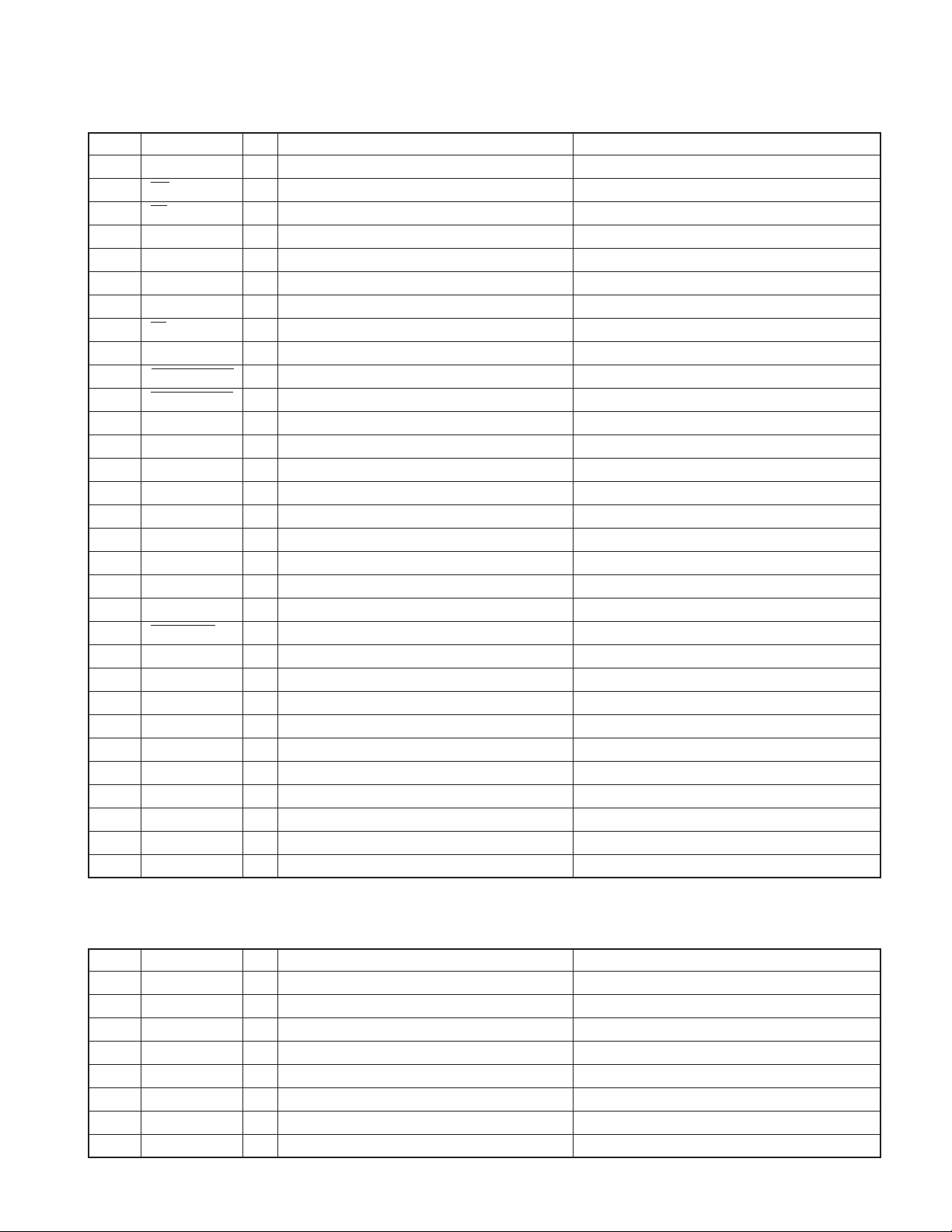
● CD receiver test mode specifications
•Jumps are made to the following tracks by pressing the
[
] key.
No. 9 → No. 15 → No. 10 → No. 11 → No. 12 → No. 13 →
No. 22 → No. 14 → No. 9 (Returns to the beginning)
It must be noted, however, that when paying MP3 / WMA /
AAC disk, which contain 8 files or less, the first track and
the following tracks are played in order.
• When [ ] key is pressed, it goes down by 1 track.
• When a CD is used as a source, by pressing [1] key for less
than 1 second, a jump to the Track No. 28 is made.
• When a CD is used as a source, by pressing [2] key for less
than 1 second, a jump to the Track No. 14 is made.
• When a CD is used as a source, by pressing [3] key for less
than 1 second, a display of CD mechanism model name
and its version is made. When the pressing of [3] key for
less than 1 second is made for the second time, the normal
display is resumed. (Time code display)
• When a CD is used as a source, by pressing [6] key for less
than 1 second, a jump to the Track No. 15 is made. At the
same time, the volume value is set to 25 (2V PRE) and 27
(5V PRE).
13

KDC-MP828/W7531/W7531Y/W8531
/W8531Y/X789/X8529/X889
TEST MODE
● Audio adjust mode
Model with DSP (KDC-MP828/X889)
•By pressing [AUD] key for less than 1 second, the Audio
Adjust mode is entered.
• As with the [AUD] key, [∗] key on the remote controller can
be used to enter the Audio Adjust mode.
• As for the adjustment items, items for both the AUDIO
FUNCTION MODE and SETUP MODE are included.
• The initial item will be Fader and the next is Balance. (After
Balance, it will be arbitrary.)
• With the remote controller, continuous forwarding is pro-
hibited.
• Using the VOL knob, the Fader is to be adjusted to the fol-
lowing 3 levels : R15 ↔ 0 ↔ F15 (The default value : 0)
• Using the VOL knob, the Balance is to be adjusted to the
following 3 levels : L15 ↔ 0 ↔ R15 (The default value : 0)
• Using the VOL knob, the Sub Woofer Level is to be ad-
justed to the following 3 levels : –15 ↔ 0 ↔ +15 (The de-
fault value : 0)
• Using the VOL knob, the Volume Offset is to be adjusted to
the following 2 levels : –8 ↔ 0 (The default value : 0)
• Using the VOL knob, the Sub Woofer Level can be adjusted
in 3 steps : –15 ↔ 0 ↔ +15 (The initial value is 0)
• Using the VOL knob, the Volume Offset can be adjusted in
2 steps : –8 ↔ 0 (The initial value is 0)
• Using the VOL knob, the HPF Front / Rear can be adjusted
in 2 steps : Through ↔ 180Hz (or 220Hz) (The initial value
is Through)
• Using the VOL knob, the LPF Sub Woofer can be adjusted
in 2 steps : 60Hz (or 50Hz) ↔ Through (The initial value is
Through)
• Using the VOL knob, the Sub Woofer Phase can be ad-
justed in 2 steps : Reverse ↔ Normal (The initial value is
Normal)
• Using the VOL knob, the Volume Offset can be adjusted in
2 steps : –8 ↔ 0 (The initial value is 0)
• Using the VOL knob, the Loudness ON/OFF can be ad-
justed in 2 steps : OFF ↔ ON (The initial value is OFF)
• 2-Zone ON/OFF can be adjusted in 2 steps : OFF ↔ ON
(The initial value is OFF)
• Bass f / Bass Q / Bass EXT / Middle f / Middle Q / Treble f
do no appear in audio adjustments.
Model with no DSP (KDC-W7531/W7531Y/W8531/
W8531Y/X789/X8529)
• By pressing [AUD] key for less than 1 second, the audio
adjustment mode can be entered.
• Using the remote controller [∗] key and [AUD] key, the au-
dio adjustment mode can be entered.
•Adjustment items of both the AUDIO FUNCTION MODE
and SETUP MODE are included.
• The initial item will be Fader, which is followed by : Balance
→ Bass Level → Middle Level → Treble Level → (Sub Woofer
Level) → HPF Front → HPF Rear → LPF Sub Woofer (Af-
ter this, it will be arbitrary)
• With the remote controller, continuous forwarding is pro-
hibited.
• Using the VOL knob, the Fader can be adjusted in 3 steps :
R15 ↔ 0 ↔ F15 (The initial value is 0)
• Using the VOL knob, the Balance can be adjusted in 3 steps
: L15 ↔ 0 ↔ R15 (The initial value is 0)
•Using the VOL knob, the Bass / Middle / Treble Level can
be adjusted in 3 steps : –8 ↔ 0 ↔ +8 (The initial value is 0)
● MENU items
• Push the [ ] (NEXT) key for at least 1 second to enter the
MENU.
• The [DNPP/SBF] and [DIRECT] keys on the remote con-
troller can also be used to enter the MENU.
• With the remote controller, continuous forwarding is pro-
hibited.
• When a CD is used as a source, the default item will be the
ACD F/W Version.
● 2-ZONE (Dual Zone) items
• When using sources other than the STANDBY source, us-
ing a short-press on [AUTO] or [TI] key, 2-ZONE ON/OFF
is achieved.
● Backup current measurement
When reset in Acc OFF (Back Up ON) condition, MUTE termi-
nal goes off after 2 seconds, instead of 15 seconds. (During
this time, the CD mechanism does not function.)
14
TEST MODE
KDC-MP828/W7531/W7531Y/W8531
/W8531Y/X789/X8529/X889
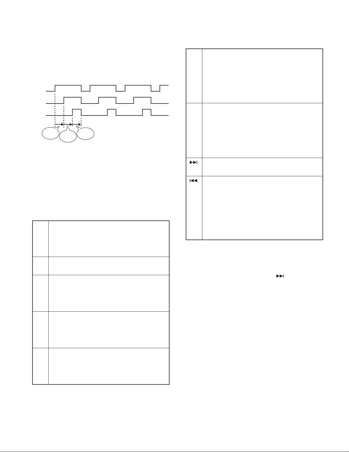
● OPEL communication items
During the test mode, OPEL communication line outputs the
following (At every 500msec, the output condition of the com-
munication line will be switched.)
CE
DATA
CLK
500msec
500msec
500msec
● G sensor display items
When source is STANDBY, by short-pressing [ATT] key, the
display is switched to analogy meter display, in which vertical
G and horizontal G are displayed.
● Special display when all lights are on
When all lights are on with the STANDBY source, the follow-
ing displays are made when the keys shown below are pressed.
[1] key Version display
(Display) C-408WK_SYS_1. 23
(Display) _________PAN_1. 11
(Display) ________MEM_3. 21
[2] key Serial number display (8 digits)
(Display) SNo_XXXXXXXX
[3] key
[4] key
[5] key
Press for less than 1 second : Power ON time is displayed.
During Power On time display, by pressing for at least 2
seconds, the Power ON time is cleared.
(Display) PonTim_XXXXX MAX 65535 (hours)
Press for less than 1 second : CD operation time is displayed.
During CD operation time display, by pressing for at least
2 seconds, CD operation time is cleared.
(Display) CDTim_0XXXXX MAX 65535 (hours)
Press for less than 1 second : CD EJECT number is displayed.
During CD EJECT number display, by pressing for at
least 2 seconds, CD EJECT number display is cleared.
(Display) EjeCnt_XXXXX MAX 65535 (times)
[6] key Press for less than 1 second : PANEL Open/close
number is displayed. (*1)
During PANEL Open/close number display, by pressing
for at least 2 seconds, PANEL Open/close numbers is
cleared.
(Display) PnCnt_XXXXXX MAX 65535(times)
[FM] ROM correction version display
key (Display) SYS_ROM_R123
(Display) PAN_ROM_R123
When E2PROM is not installed : ROM_ERR_
When un-written : ROM_R – – –
When data is incompatible : ROM_R ∗ ∗ ∗
AUDIO data default value setting
key (Display) AUDIO_INIT
Press for less than 1 second : CD mechanism error log display
key During CD mechanism error log display; by pressing for
at least 2 seconds, all error log information is cleared.
(Display) I2C_●●
(Display) ERR_1–▲▲, 2–▲▲, 3–▲▲
∗ In “●●”, “OK” or ”NG” is displayed.
In “▲▲”, “– –” or an error code is displayed.
(*1) : 1 count is made when the panel opens to full or when a disc is
loaded.
● Initializing AUDIO-related value setting
During STANDBY sourcing, by pressing [ ] key for less than
1 second, AUDIO setting values are returned to the default
values.
● Flash ROM check
1. In order to prevent the Flash ROM (4M) equipped models
to be installed with the Mask ROM (2M) panel, and to pre-
vent the Mask ROM (2M) equipped models to be installed
with the Flash ROM (4M) panels, with the STANDBY
sources during the test mode, the following display will be
made according to the system µ-com and panel combina-
tion.
•
Flash ROM (4M) equipped model and Flash ROM (4M) panel
All lights turned on – – – OK!
•
Mask ROM (2M) equipped model and Mask ROM (2M) panel
All lights turned on – – – OK!
•
Flash ROM (4M) equipped model and Mask ROM (2M) panel
“M4P2” – – – NG!
•
Mask ROM (2M) equipped model and Flash ROM (4M) panel
“M2P4” – – – NG!
15
KDC-MP828/W7531/W7531Y/W8531
/W8531Y/X789/X8529/X889
TEST MODE
2. When entering the test mode, the manufacture code of the
Flash ROM (4M) is read and when it is normal, FROMCHK
of the 100th terminal (Panel µ-com) repeats Hi → Low →
Hi · · ·. If the reading is abnormal, “Low” is output.
If the manufacture code is normal, by pressing [ ] key for
less than 1 second, the connection checks on all terminal
is started. If the connections are normal, the FROMCHK
terminal stops the Hi → Low → Hi · · · repeating and out-
puts “Hi”. If the reading is abnormal, “Low” is output.
3. With all lights turned on and by pressing [AM] key for at
least 1 second, the data on the Flash ROM (4M) is initial-
ized. While erasing the data, “Data_Erase....” is displayed.
Note : Do not touch any key white this is in progress.
When erasing is complete, “Erase_OK!!” is displayed.
If “Erase_NG!!!!!!” is displayed, it was not possible to erase
the data on the Flash ROM (4M).
In this case, pressing [AM] key for at least 1 second again.
If it is the same, then there is an abnormality with the Flash
ROM.
● Other
• At Power ON, “CODE_OFF”, “CODE_ON” displays will not
be made.
• When sourcing STANDBY, by pressing [AUTO] or [TI] key
for less than 1 second, GREEN/RED of the key illumination
is switched.
When doing this, the triangle illumination GREEN/RED is
switched along with the key illumination.
• When staring up in the test mode, LINE MUTE prohibition
time is set to 1 second instead of 10 seconds.
• While in the test mode, even when a DC offset error is de-
tected, the detection information will not be written to the
E2PROM.
• While in the test mode, even after an elapse of pre-set time,
the backup memory items will not be written to the E2PROM.
• Information Clear mode for Test Mode, backup/installer
memory, and CD mechanism error log.
In the DC offset error detection information clear mode,
DEMO mode operation will not be conducted.
Also, in the above mode, the menu of the STANDBY source
will not display DEMO ON/OFF switching items.
• While in the test mode, and at the same time, PM_DET of
the 60th terminal (System µ-com) is H, the following will
apply to the EJECT key, regardless of whether a disc is in
the unit or not.
Panel full OPEN/CLOSE is conducted with a push for less
than 1 second. (Protection time : 3 seconds)
As far as this item is concerned, eject will be achieved by
for at least 1 second push on the EJECT key.
● Clearing backup memory and installer memory
data (Clearing E2PROM data)
1. By pressing [ ] (NEXT) key and [ATT] key simultaneously,
reset and start the unit. This will start the initialization pro-
cesses for backup and installer memory data and the error
log information of the CD mechanism.
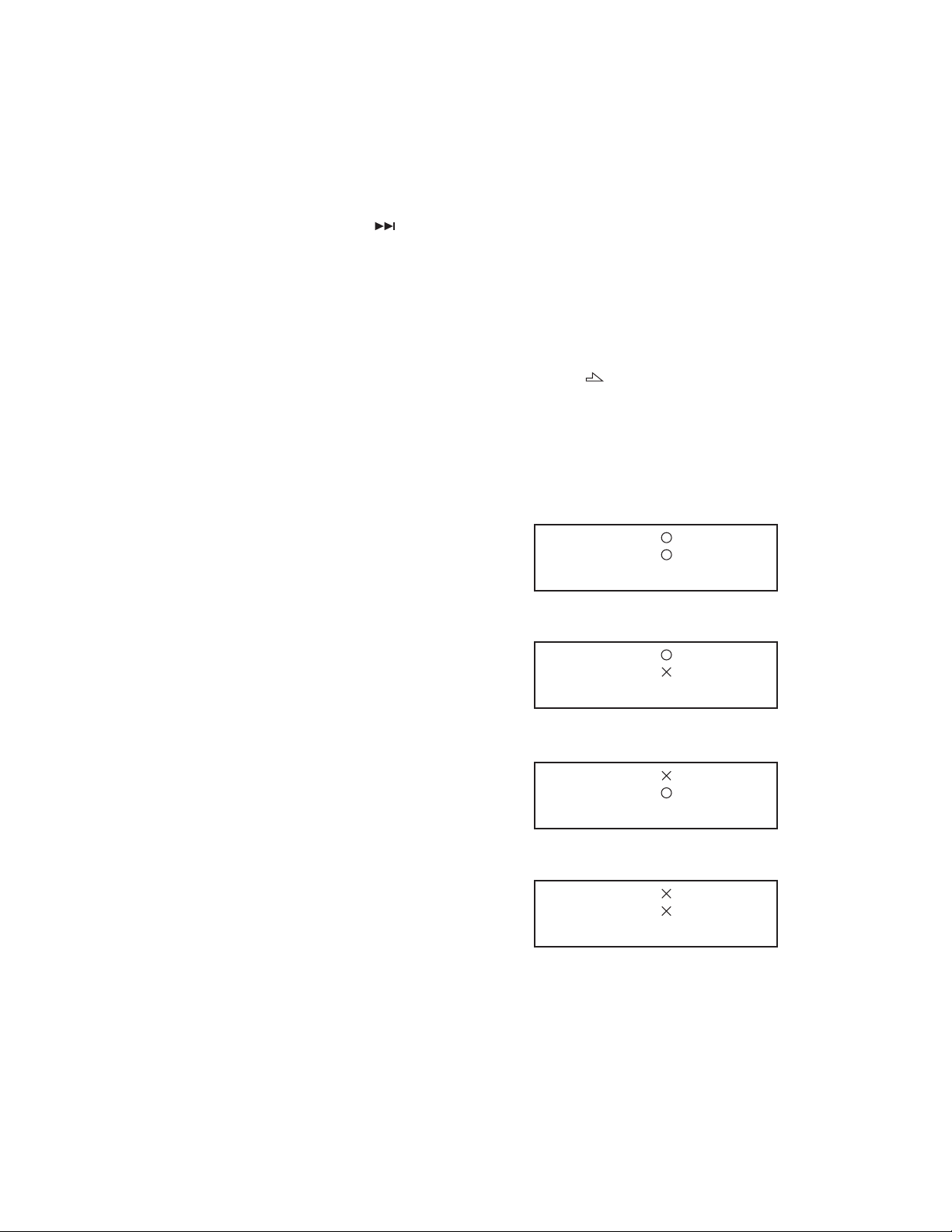
2. When initialization is complete, the following display will be
made.
Normal completion
C D _ E 2 P _ _ _ :
A U D I O _ E 2 P :
Abnormal ending 1 : backup/installer memory initialization : NG
C D _ E 2 P _ _ _ :
A U D I O _ E 2 P :
Abnormal ending 2 : CD mechanism error log initialization : NG
C D _ E 2 P _ _ _ :
A U D I O _ E 2 P :
Abnormal ending 3 : All initialization : NG
C D _ E 2 P _ _ _ :
A U D I O _ E 2 P :
3. While in this mode, even after an elapse of a pre-set time,
no backup memory items will be written to the E2PROM.
4. This mode is released by resetting. (What was on the last
screen will not be retained.)
16

TEST MODE
KDC-MP828/W7531/W7531Y/W8531
/W8531Y/X789/X8529/X889
● Clearing DC offset error detection information
(E2PROM data clear)
1. While simultaneously pressing down on [3] and [6] keys,
reset the unit to enter the DC offset error display mode.
2. During STANDBY sourcing, the current DC offset error con-
ditions will be displayed.
When error detected : “DC_ERR”
When error not detected : “DC_OK”
3. While the error conditions are being displayed, press [AUTO]
or [TI] key for less than 1 second to clear the detection
information. (E2PROM clear)
4. DC offset error display mode is released by resetting. (What
was on the last screen will not be retained.)
● FM/AM channel space switching
(KDC-MP828/X789/X8529/X889)
From the Power OFF condition, while pressing [1] and [5] keys
down simultaneously, press the [SRC] key and turn power ON.
● Security
• Forced Power ON mode
While “– – – –” is being displayed, by resetting while pressing
] (NEXT) key and [4] key simultaneously, it is possible to
[
turn the power ON for 30 minutes only.
• How to register the security code on the “Car Au-
dio Passport” after replacement of the E2PROM
(KDC-W7531/W7531Y/W8531/W8531Y/X8529)
1. Enter the test mode. (Refer to the section on “How to Enter
the Test Mode.”)
2. Enter the MENU by long pressing [ ] (NEXT) key for one
second.
While “Security” is being displayed, press [ ] key for at
least 1 second and enter the security registration mode.
3. Using [FM] / [AM] / [ ] / [ ] keys, enter the code.
[FM] key : Number up / [AM] key : Number down
[ ] key : Cursor Right / [ ] key : Cursor Left
4. Press [
TER”. Then, re-enter the code using the method in above
No. “3”.
5. Press [
PROVED”.
6. Release the test mode. (Refer to the section on “How to
Release the Test Mode.”)
Note : The security code for this model cannot be deleted by
“all clear” command.
] key for at least 3 seconds to display “RE-EN-
] key for at least 3 seconds to display “AP-
● Method of clearing the programmable security
code (KDC-MP828/X789/X889)
1. While “– – – –” is being displayed, press [ ] key for at
least 3 seconds while pressing [AUTO] key.
This makes “– – – –” display disappear.
2. Using the remote controller, input “KCAR”.
Press remote controller [5] key 2 times (Input for “K”) and
then press [
Press remote controller [2] key 3 times (Input for “C”) and
then press [ ] key.
Press remote controller [2] key once (Input for “A”) and then
press [ ] key.
Press remote controller [7] key 2 times (Input for “R”) and
then press [ ] key.
3. The security is released and the unit enters the STANDBY
mode.
4. If a wrong code is input, the unit goes into the Code Re-
quest mode.
] key.
17
 Loading...