

Kenwood KDC-C715Y Service Manual

CD AUTO CHANGER
KDC-C715/Y
SERVICE MANUAL
KDC-C715/Y
© 1999-12 PRINTED IN JAPAN
B51-7553-00 (N) 3444
When transporting this model, always attach CAUTION
CARD and STEPPED SCREW (for transportation).
CAUTION CARD : B58-1275-04
STEPPED SCREW : N09-4186-25
Dressing Panel
(A21-3536-12)
Holder Assy (Magazine)
(J19-4676-52)
Dressing Panel
(A21-3539-12)
Service jig Parts No.
For initial position setting W05-0635-00
Panel
(A64-1992-01)
COMPACT DISC AUTO CHANGER KDC-C715
NEW ANTI VIBRATION MECHANISM DISC NAME PRESET
COMPACT
DIGITAL AUDIO
TEXT
DISC
10
Bracket (L)
(J19-4710-13)
Bracket (R)
(J19-4711-13)
Blind Plate
(F19-1303-04)
Screw Set
K/E T ype:
(N99-1645-15)
M T ype:
(N99-1628-15)
Adhessive Tape
(J69-0506-04)
Mounting Hardware Assy
(J21-7775-04)
M T ype Only
Cord With Plug
(E30-4138-05)
The MECHANISM OPERATION DESCRIPTION is the same as model KDC-C710.
Please refer to the service manual of model KDC-C710 (B51-7104-00).

KDC-C715/Y
M5V1
LIM SW
L.P.S.
S4 COMM SW
S2 EJ SW
S3 ARM SW
12.5MHz
AVREF0
X2
SPINDLE
PD
PICKUP ASSY
(X13-973)
(X32-466)
(X13-900)
SLED
LOE SW
TR COIL
FO COIL
E
D
B
AC
MOTOR
DRIVER
BTL & DC
ELEVATOR
EEPROM
S-24C01B
HOT
TEXT DECODER &
APC
SD5V
Q1
S8V
LA6556
Q9
UPD784214GC-062-8EU
SYSTEM u-COM
IC7
IC1
RF AMP & SERVO DSP &
16.93MHz
X1
P ON
Q10
7V/9V
M5V1
M5V2
RESET
IC9
Q15,16
8V AVR
Q20
Q21,22
BU.DET
5V AVR
BU14V
DA5V
MUTE
5VREG
S8V
CH CON
CH RST
CH MUTE
5L I/F
AUDIO OUT
T0
IC8
7
4
5
8
2
5
Q6-8
IC4
IC5
AVR
S5V
13
IC11
LC3564ST-70
S-RAM
24
2
S8V
Q12
S1 MG SW
3
HEAD
UNIT
M
MM
SA5V
UPD63711GC
D/A CONVERTER & SCF
OBIT
MUTE
Q4,5
F
BLOCK DIAGRAM
2

KDC-C715/Y
MICROCOMPUTER’S TERMINAL DESCRIPTION
UPD784214GC (X32-4660-00, IC7)
Pin No
1 TOUT O Test output
2 TSTB O Text data strobe signal
3 - O NC.
4 FOK I H: Focusing OK. L:Focusing NG.
5 X OFF O H: Servo IC oscillation OFF.
6 RST O L: Servo IC reset.
7 AO O H: Parameter setting. L: Address register setting.
8 STB O L: Data latch.
9 VDD Power supply connection.
10 X2 - Oscillator.
11 X1 I Oscillator.
12 VSS I GND.
13 XT2 - NC.
14 XT1 GND.
15 RESET I L:Reset.
16 BSY
17 MGSW I H:Holder IN. L:Holder OUT.
18 EJSW I H:Eject.
19 COMMSW I H:New. L:Old.
20 PACK I Text data pack sync signal.
21 CHCON I Changer control.
22 BUDET I B-U detection.
23 AVDD I A/D converter power supply.
24 AVREF I A/D converter reference voltage.
25 HOT I High temperature detection.
26 LPS I Position detection.
27 LOESW I L:Loading completed.
28 LIMSW I L:PU limit switch ON.
29 TOFF I Tracking off mode.
30 ADJSEL I H:Service adjustment OFF. L:Servo adjustment ON.
31 TBANK I H:Gain UP. L:Normal.
32 SIM3
33 AVSS GND.
34 LPSCO O A/D converter power supply. H:OFF.
35 AMUTE O L:Muting ON.
36 AVREF1 A/D converter power supply.
37 SDI I Servo data input.
38 SDO O Servo data output.
39 SCK O Servo clock output.
40 DATAH I Data input from H/U.
Name I/O Processing, Operation
3
KDC-C715/Y
MICROCOMPUTER’S TERMINAL DESCRIPTION
Pin No
41 DATAC O Data output to H/U.
42 HCLK I/O H:Clock input. L:Clock output.
43 REQC O Communication request to H/U.
44 CHMUTE O L:Muting ON.
45 TSO O Text data output.
46 TSI I Text data input.
47 TSCK O Text clock output.
48Å`55
A0Å`7 O S-RAM address setting.
56Å`63
D0Å`7 I/O S-RAM data input/output.
64Å`68
A8Å`12 O S-RAM address setting.
69Å`71
A13Å`15 O S-RAM enable control.
72 VSS GND.
73,74 A16,17 O S-RAM enable control.
75 RAMOK O H:OK.
76 ELVADJ I L:Adjustment mode.
77 RD O S-RAM read control.
78 WR O S-RAM write control.
79 WAIT I Wait during S-RAM access.
80 ASTB O NC.
81 VDD Power supply connection.
82 RAMTEST I H:S-RAM check mode.
83 REQH I Communication request from H/U.
84 SP/LO+ O Spindle/Loading+ control.
85 SP/LO- O Spindle/Loading- control.
86 ELV+ O Mechanism UP/DOWN control.
87 ELV- O Mechamism UP/DOWN control.
88 SIM1 I L:Text. H:No text.
89 SEARCH O H:Play. L:Search.
90,91 TEST1,2 I L:Normal. H:Test.
92 8V/7V O H:7V. L:8V(Servo power supply).
93 SLG I H:+3dB. L:0dB(Sled gain).
94 TEST/VPP I L:Flash ROM program mode OFF.
95 SRVSEL I H:Servo mode.
96 SLNSA I L:Sled non-sensible area ON.
97 SDA I/O EEPROM data input/output.
98 SCL O EEPROM clock output.
99 PON O L:Power ON.
100 ARMSW I H:Arm switch ON.
Name I/O Processing, Operation
4
ADJUSTMENT
LPS initial position adjustment procedure
Connect the changer to the H/U. While holding the magazine eject button of the changer, press the reset button of
the H/U and, in about 1 second, release the magazine eject
button. Press the CD button of the H/U to enter the E-88
mode. Move the mechanism deck to around the 1st stage
by pressing the DISC- or DISC+ button.
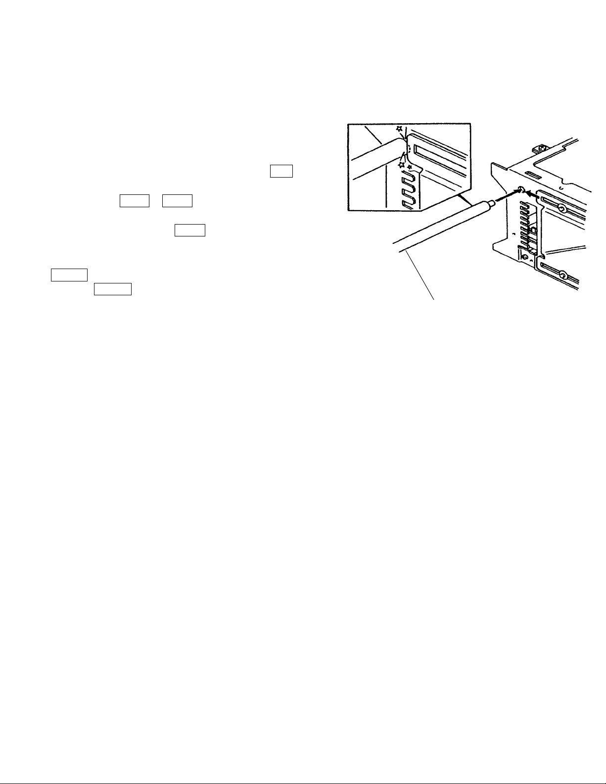
Insert the adjustment tool into the tool hole on the changer
mechanism. Then press the DISC+ button to move the
mechanism deck until the mechanism's slider hits the
adjustment tool. When the motor locks(stops) press the
REPEAT key of the H/U.
When the REPEAT key is pressed, the mechanism moves
automatically to the 1st stage and the initial position adjustment completes. (The data is written in the E2PROM
at this time.)
KDC-C715/Y
(W05-0635-01)
5
 Loading...