

Kenwood KDC-152, KDC-153, KDC-153S Service Manual
SERVICE MANUAL
CD RECEIVER
WA001<Rev.001>201110SERVICE MANUALB53-0892-00
KDC-152, KDC-153, KDC-153S
Tuner setting adjustment after replacing E2PROM
After replacing E2PROM (IC771 on ELECTRIC UNIT), tuner setting adjustment is needed.
The adjustment is that to perform the "TUNER Setting Adjustment Mode" in the TEST MODE.
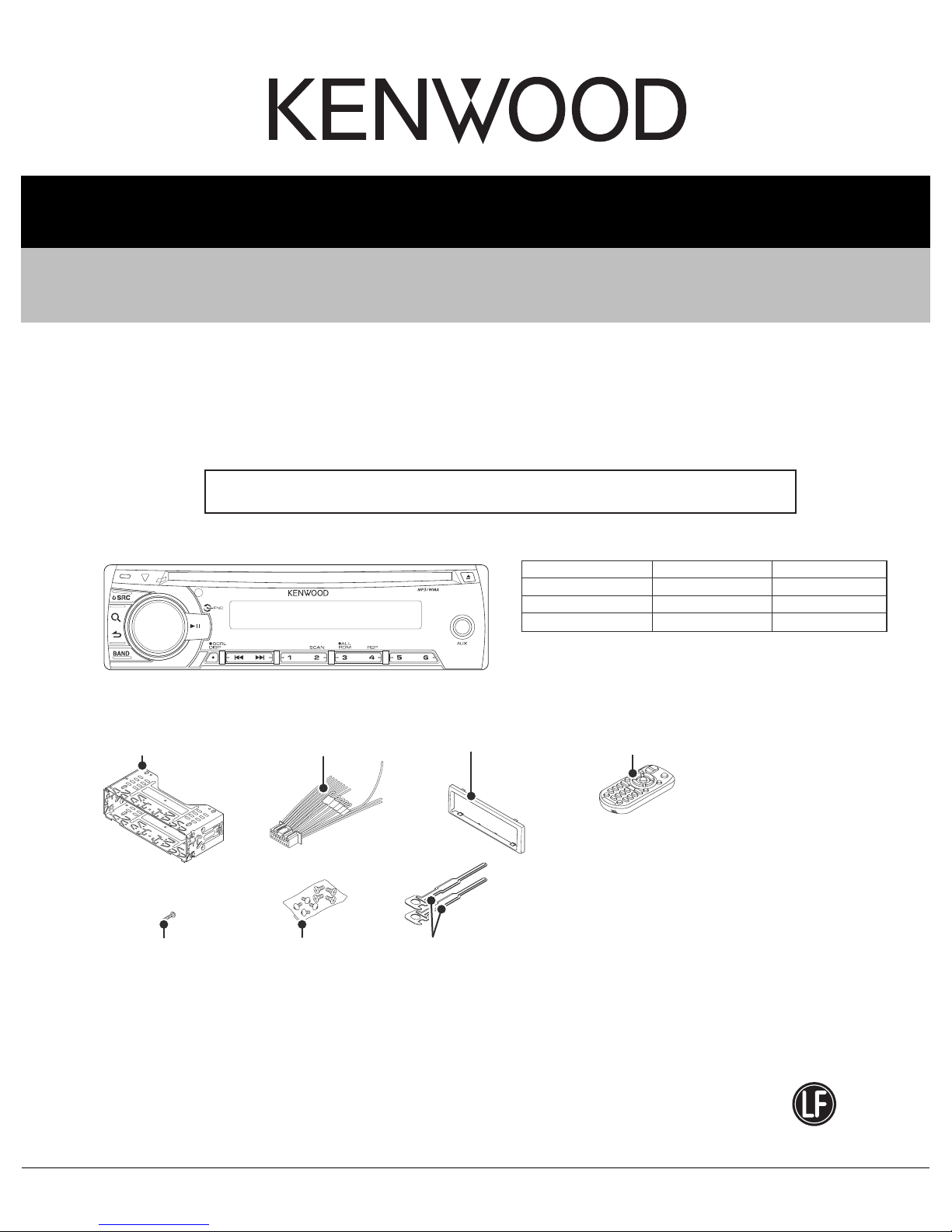
Illustration is KDC-152
M. sleeve assy
(GE34826-001A)
Tap screw (2x8)
(QYSPSF2008MA)
DC cord
(QAM1335-001)
Screw set
(GE40536-001A)
KDC-152
Trim plate
(GE20274-001A)
Hook
(GE40578-001A) x2
TDF SPARE-PANEL
MAIN UNIT NAME TDF PARTS No. TDF NAME
KDC-152
KDC-153
KDC-153S
Remocon unit (RC-405)
(QAL1303-001)
Y33-3350-13
Y33-3370-27
Y33-3370-28
TDF-1215D
TDF-153
TDF-153S
COPYRIGHT © 2011 JVC KENWOOD Corporation
B53-0892-00
COPYRIGHT © 2011 JVC KENWOOD Corporation
This product uses Lead Free solder.
This product complies with the RoHS directive for the European market.
PbF
No.WA001<Rev.001>
2011/10

SPECIFICATION
Model for destination "K" (KDC-152)
FM tuner section
Frequency range (200 kHz space) 87.9 MHz - 107.9 MHz
Usable sensitivity (S/N= 26 dB) 11.2 dBf (1.0 µV/75 Ω)
Quieting sensitivity (DIN S/N = 46 dB) 19.2 dBf (2.5 µV/75 Ω)
Frequency response (± 3 dB) 30 Hz - 15 kHz
Signal-to-Noise ratio (MONO) 63 dB
Stereo separation (1 kHz) 40 dB
AM tuner section
Frequency range (10 kHz space) 530 kHz - 1 700 kHz
Usable sensitivity (S/N= 20 dB) 31 dBµ (36 µV)
CD player section
Laser diode GaAIAs
Digital filter (D/A) 8 Times Over Sampling
D/A converter 24 Bit
Spindle speed 500 rpm - 200 rpm (CLV)
Wow & Flutter Below Measurable Limit
Frequency response (± 1 dB) 20 Hz - 20 kHz
Total harmonic distortion (1 kHz) 0.01%
Signal-to-Noise ratio (1 kHz) 105 dB
Dynamic range 90 dB
MP3 decode Compliant with MPEG-1/2 Audio Layer-3
WMA decode Compliant with Windows Media Audio
Audio section
Maximum output power 50 W × 4
Full bandwidth power (at less than 1 % THD)
Speaker impedance 4 Ω - 8 Ω
Tone action Bass 100 Hz ± 8 dB
Middle 1 kHz ± 8 dB
Treble 10 kHz ± 8 dB
Preout level / load (CD) 2 000 mV/10 kΩ
Preout impedance ≤ 600 Ω
Auxiliary input section
Frequency response (± 3 dB)
Input maximum voltage 1 200 mV
Input impedance 10 kΩ
General
Operating voltage (11 V - 16 V allowable) 14.4 V
Maximum current consumption 10 A
Installation size (W × H × D) 182 mm × 53 mm × 158 mm (7-3/16" × 2-1/16" × 6-1/4")
Weight 2.9 lbs (1.3 kg)
22 W × 4
20 Hz - 20 kHz
Subject to change without notice.
(No.WA001<Rev.001>)2/18

SPECIFICATION
Models for destination "M" (KDC-153, KDC-153S)
FM tuner section
Frequency range (200 kHz space) 87.9 MHz - 107.9 MHz
Frequency range (50 kHz space) 87.5 MHz - 108.0 MHz
Usable sensitivity (S/N= 26 dB) 11.2 dBf (1.0 µV/75 Ω)
Quieting sensitivity (DIN S/N = 46 dB) 19.2 dBf (2.5 µV/75 Ω)
Frequency response (± 3 dB) 30 Hz - 15 kHz
Signal-to-Noise ratio (MONO) 63 dB
Stereo separation (1 kHz) 40 dB
AM tuner section
Frequency range Band 1 (MW) 530 kHz - 1 700 kHz (10 kHz space)
531 kHz - 1 611 kHz (9 kHz space)
Band 2 (SW1) 2 940 kHz - 7 735 kHz (5 kHz space)
Band 3 (SW2)
Usable sensitivity (S/N= 20 dB) MW: 31 dBµ (36 µV)
CD player section
Laser diode GaAIAs
Digital filter (D/A) 8 Times Over Sampling
D/A converter 24 Bit
Spindle speed 500 rpm - 200 rpm (CLV)
Wow & Flutter Below Measurable Limit
Frequency response (± 1 dB) 20 Hz - 20 kHz
Total harmonic distortion (1 kHz) 0.01%
Signal-to-Noise ratio (1 kHz) 105 dB
Dynamic range 90 dB
Audio section
Maximum output power 50 W × 4
Full bandwidth power (at less than 1 % THD)
Speaker impedance 4 Ω - 8 Ω
Tone action Bass 100 Hz ± 8 dB
Middle 1 kHz ± 8 dB
Treble 10 kHz ± 8 dB
Preout level / load (CD) 2 000 mV/10 kΩ
Preout impedance ≤ 600 Ω
Auxiliary input section
Frequency response (± 3 dB)
Input maximum voltage 1 200 mV
Input impedance 10 kΩ
General
Operating voltage (11 V - 16 V allowable) 14.4 V
Maximum current consumption 10 A
Installation size (W × H × D) 182 mm × 53 mm × 158 mm
Weight 1.3 kg
9 500 kHz - 10 135 kHz /11 580 kHz - 18 135 kHz (5 kHz space)
SW: 32 dBµ (40 µV)
22 W × 4
20 Hz - 20 kHz
Subject to change without notice.
(No.WA001<Rev.001>)3/18
SECTION 1
PRECAUTION
1.1 Safety Precautions
(1) This design of this product contains special hardware and
many circuits and components specially for safety purposes. For continued protection, no changes should be made
to the original design unless authorized in writing by the
manufacturer. Replacement parts must be identical to
those used in the original circuits. Services should be performed by qualified personnel only.
(2) Alterations of the design or circuitry of the product should
not be made. Any design alterations of the product should
not be made. Any design alterations or additions will void
the manufacturers warranty and will further relieve the
manufacture of responsibility for personal injury or property
damage resulting therefrom.
(3) Many electrical and mechanical parts in the products have
special safety-related characteristics. These characteristics are often not evident from visual inspection nor can the
protection afforded by them necessarily be obtained by using replacement components rated for higher voltage, wattage, etc. Replacement parts which have these special
safety characteristics are identified in the Parts List of Service Manual. Electrical components having such features
are identified by shading on the schematics and by ( ) on
the Parts List in the Service Manual. The use of a substitute
replacement which does not have the same safety characteristics as the recommended replacement parts shown in
the Parts List of Service Manual may create shock, fire, or
other hazards.
(4) The leads in the products are routed and dressed with ties,
clamps, tubings, barriers and the like to be separated from
live parts, high temperature parts, moving parts and/or
sharp edges for the prevention of electric shock and fire
hazard. When service is required, the original lead routing
and dress should be observed, and it should be confirmed
that they have been returned to normal, after reassembling.
(5) Leakage shock hazard testing
After reassembling the product, always perform an isolation check on the exposed metal parts of the product (antenna terminals, knobs, metal cabinet, screw heads,
headphone jack, control shafts, etc.) to be sure the product
is safe to operate without danger of electrical shock.Do not
use a line isolation transformer during this check.
• Plug the AC line cord directly into the AC outlet. Using a
"Leakage Current Tester", measure the leakage current
from each exposed metal parts of the cabinet, particularly any exposed metal part having a return path to the
chassis, to a known good earth ground. Any leakage current must not exceed 0.5mA AC (r.m.s.).
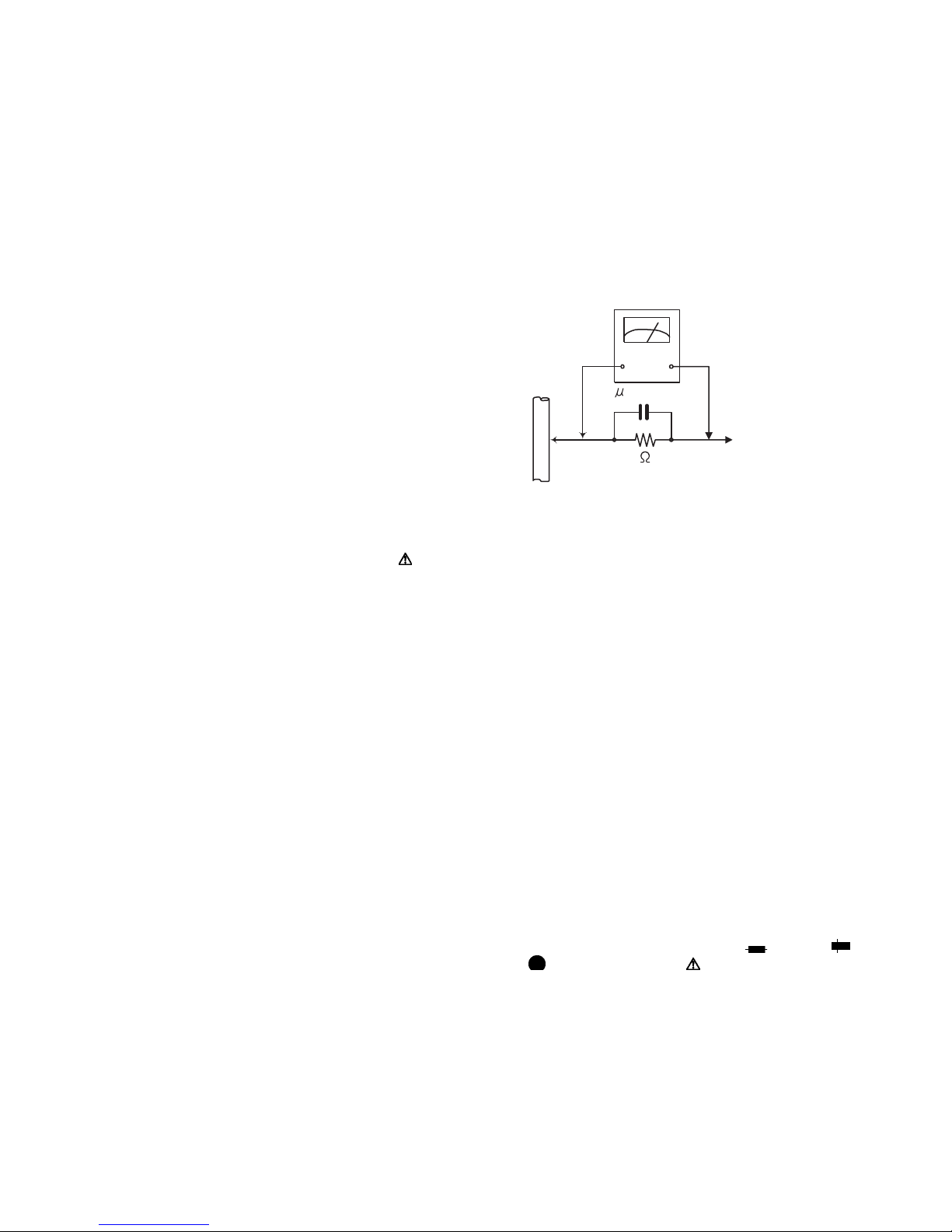
• Alternate check method
Plug the AC line cord directly into the AC outlet. Use an
AC voltmeter having, 1,000Ω per volt or more sensitivity
in the following manner. Connect a 1,500Ω 10W resistor
paralleled by a 0.15µF AC-type capacitor between an ex-
posed metal part and a known good earth ground.
Measure the AC voltage across the resistor with the AC
voltmeter.
Move the resistor connection to each exposed metal
part, particularly any exposed metal part having a return
path to the chassis, and measure the AC voltage across
the resistor. Now, reverse the plug in the AC outlet and
repeat each measurement. Voltage measured any must
not exceed 0.75 V AC (r.m.s.). This corresponds to 0.5
mA AC (r.m.s.).
AC VOLTMETER
(Having 1000
ohms/volts,
or more sensitivity)
0.15 F AC TYPE
Place this
probe on
1500 10W
Good earth ground
1.2 Warning
(1) This equipment has been designed and manufactured to
meet international safety standards.
(2) It is the legal responsibility of the repairer to ensure that
these safety standards are maintained.
(3) Repairs must be made in accordance with the relevant
safety standards.
(4) It is essential that safety critical components are replaced
by approved parts.
(5) If mains voltage selector is provided, check setting for local
voltage.
1.3 Caution
Burrs formed during molding may be left over on some parts
of the chassis.
Therefore, pay attention to such burrs in the case of preforming repair of this system.
1.4 Critical parts for safety
In regard with component parts appearing on the silk-screen
printed side (parts side) of the PWB diagrams, the parts that are
printed over with black such as the resistor ( ), diode ( )
and ICP ( ) or identified by the " " mark nearby are critical
for safety. When replacing them, be sure to use the parts of the
same type and rating as specified by the manufacturer.
(This regulation dose not Except the J and C version)
each exposed
metal part.
(No.WA001<Rev.001>)4/18
1.5 Preventing static electricity
Electrostatic discharge (ESD), which occurs when static electricity stored in the body, fabric, etc. is discharged, can destroy the laser
diode in the traverse unit (optical pickup). Take care to prevent this when performing repairs.
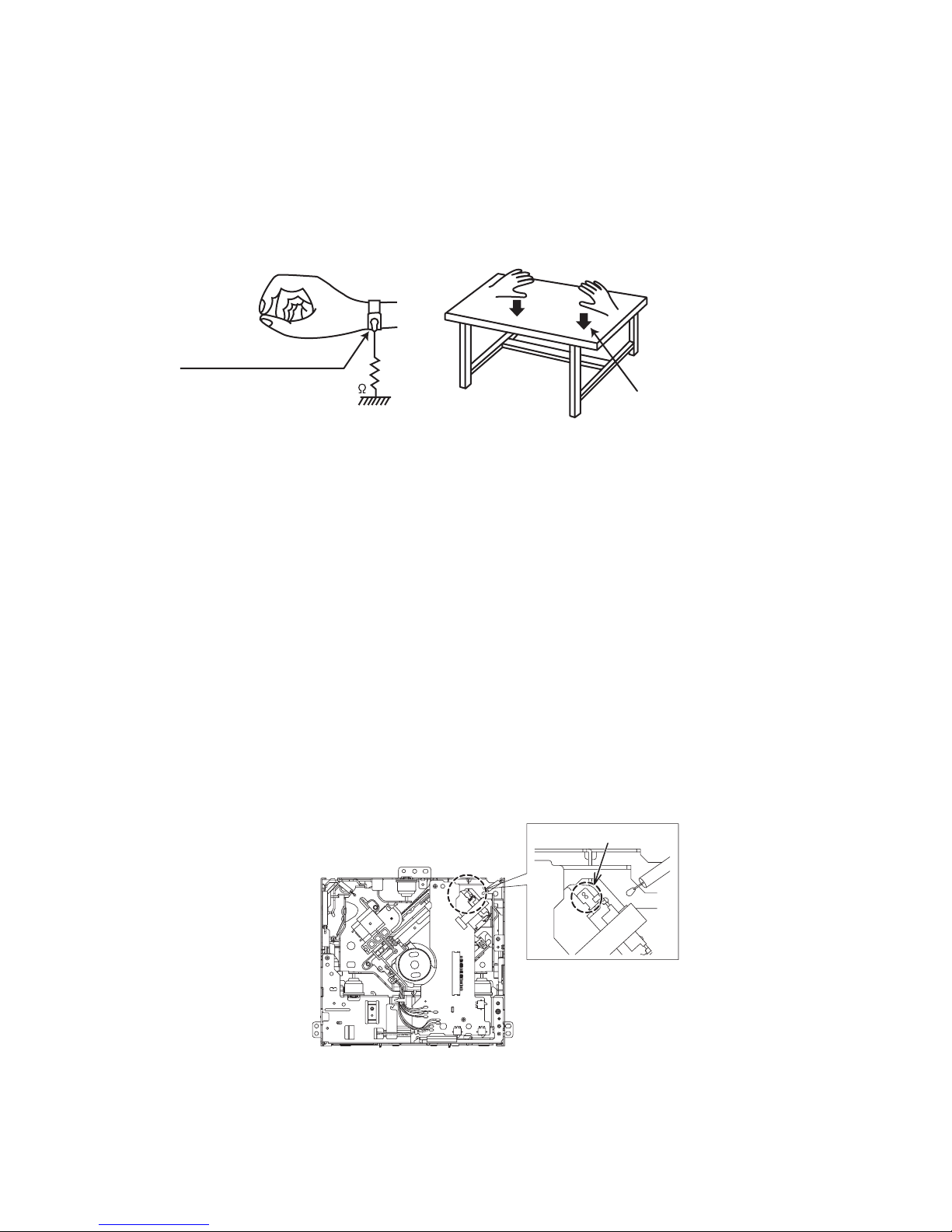
1.5.1 Grounding to prevent damage by static electricity
Static electricity in the work area can destroy the optical pickup (laser diode) in devices such as laser products.
Be careful to use proper grounding in the area where repairs are being performed.
(1) Ground the workbench
Ground the workbench by laying conductive material (such as a conductive sheet) or an iron plate over it before placing the
traverse unit (optical pickup) on it.
(2) Ground yourself
Use an anti-static wrist strap to release any static electricity built up in your body.
(caption)
Anti-static wrist strap
1M
Conductive material
(conductive sheet) or iron palate
(3) Handling the optical pickup
• In order to maintain quality during transport and before installation, both sides of the laser diode on the replacement optical
pickup are shorted. After replacement, return the shorted parts to their original condition.
(Refer to the text.)
• Do not use a tester to check the condition of the laser diode in the optical pickup. The tester's internal power source can easily
destroy the laser diode.
1.6 Handling the traverse unit (optical pickup)
(1) Do not subject the traverse unit (optical pickup) to strong shocks, as it is a sensitive, complex unit.
(2) Cut off the shorted part of the flexible cable using nippers, etc. after replacing the optical pickup. For specific details, refer to the
replacement procedure in the text. Remove the anti-static pin when replacing the traverse unit. Be careful not to take too long a
time when attaching it to the connector.
(3) Handle the flexible cable carefully as it may break when subjected to strong force.
(4) I t is not possible to adjust the semi-fixed resistor that adjusts the laser power. Do not turn it.
1.7 Attention when traverse unit is decomposed
*Please refer to "Disassembly method" in the text for the pickup unit.
• Apply solder to the short land sections before the card wire is disconnected from the connector on the servo board. (If the card wire
is disconnected without applying solder, the pickup may be destroyed by static electricity.)
• In the assembly, be sure to remove solder from the short land sections after connecting the card wire.
SOLDER
(No.WA001<Rev.001>)5/18
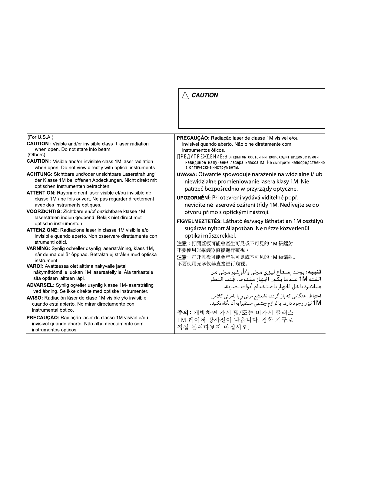
1.8 Important for laser products
1.CLASS 1 LASER PRODUCT
2.CAUTION :
(For U.S.A.) Visible and/or invisible class II laser radiation
when open. Do not stare into beam.
(Others) Visible and/or invisible class 1M laser radiation
when open. Do not view directly with optical instruments.
3.CAUTION : Visible and/or invisible laser radiation when
open and inter lock failed or defeated. Avoid direct
exposure to beam.
4.CAUTION : This laser product uses visible and/or invisible
laser radiation and is equipped with safety switches which
prevent emission of radiation when the drawer is open and
the safety interlocks have failed or are defeated. It is
dangerous to defeat the safety switches.
5.CAUTION : If safety switches malfunction, the laser is able
to function.
6.CAUTION : Use of controls, adjustments or performance of
procedures other than those specified here in may result in
hazardous radiation exposure.
!
Please use enough caution not to
see the beam directly or touch it
in case of an adjustment or operation
check.
SPECIFIC SERVICE INSTRUCTIONS
This service manual does not describe SPECIFIC SERVICE INSTRUCTIONS.
SECTION 2
(No.WA001<Rev.001>)6/18
SECTION 3
DISASSEMBLY
3.1 Main body (Used model: KDC-152)
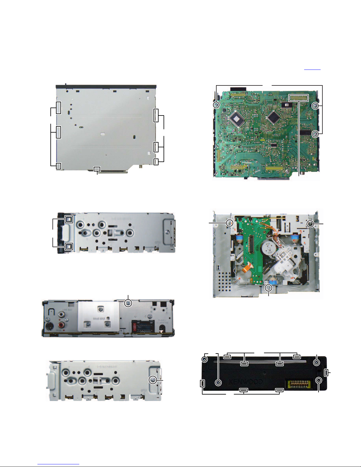
3.1.1 Removing the Bottom chassis (See Fig.1)
(1) Disengage the 7 hooks a engaging the Bottom chassis.
(2) Slide the Bottom chassis backward to remove it.
hook a
hook a
hook a
Fig.1
3.1.2 Removing the Front chassis (See Fig.2)
(1) Disengage the 4 hooks b engaging both sides of the Front
chassis.
hook b
(3) Remove the 3 screws C attaching the Electric unit. (See
Fig.5)
(4) Disconnect the board to board connector CN502
ing the Electric unit and the CD mechanism. (See Fig.5)
connect-
C
CN502
Fig.5
3.1.4 Removing the CD mechanism (See Fig.6)
(1) Remove the 3 screws J attaching the CD mechanism.
D
D
Fig.2
3.1.3 Removing the Electric unit (See Fig.3, 4 and 5)
(1) Remove the 1 screws A attaching the Rear bracket. (See
Fig.3)
A
Fig.3
(2) Remove the 2 screws B attaching both sides of the Top
chassis. (See Fig.4)
B
Fig.4
D
Fig.6
3.1.5 Removing the Switch unit (See Fig.7)
(1) Remove the Volume knob.
(2) Remove the 4 screws E attaching the Rear cover.
(3) Disengage the 8 hooks c engaging the Rear cover.
E
c
c
Fig.7
E
c
E
(No.WA001<Rev.001>)7/18
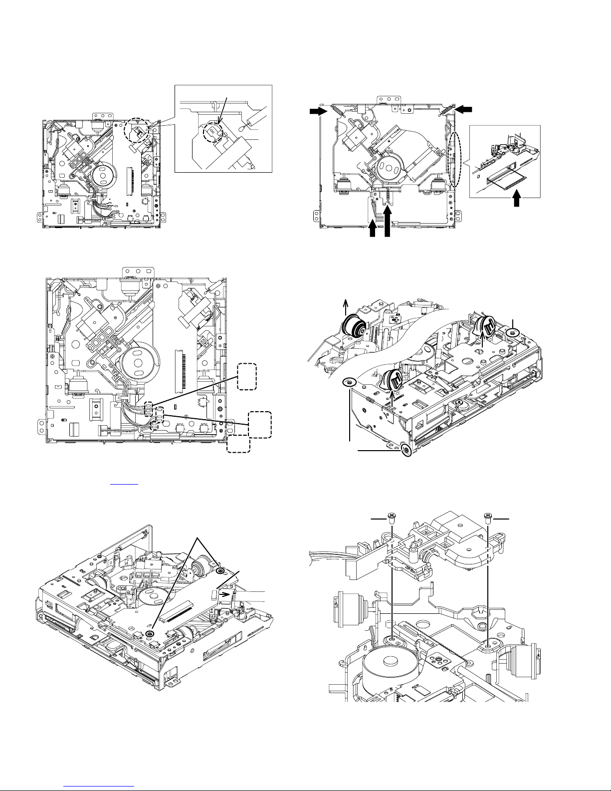
3.2 CD mechanism assembly section
3.2.1 Removing the Mecha control board
(1) Solder the short land on the pickup. (See Fig. 1)
SOLDER
3.2.2 Removing the Traverse mechanism (See Fig.4, 5)
(1) Remove the five springs from the traverse mechanism.
(See Fig.4)
Fig.1
(2) Remove the eight wires from the Mecha control board.
(See Fig.2)
BLACK
RED
WHITE
YELLOW
ORANGE
ORANGE
WHITE
YELLOW
Fig.2
(3) Disconnect the flexible wire from the pickup connected to
the connector CN102
on the Mecha control board. (See
Fig.3)
(4) Remove the two screws A attaching the Mecha control
board. (See Fig.3)
A
Fig.4
(2) Remove the three screws B attaching the bottom frame as-
sembly. (See Fig.5)
(3) Remove the three dumpers from the bottom frame assem-
bly. (See Fig.5)
B
B
Fig.5
3.2.3 Removing the Pickup (See Fig.6, 7)
(1) Remove the two screws C attaching the feed bracket as-
sembly. (See Fig.6)
CC
Fig.3
CN102
Fig.6
(No.WA001<Rev.001>)8/18
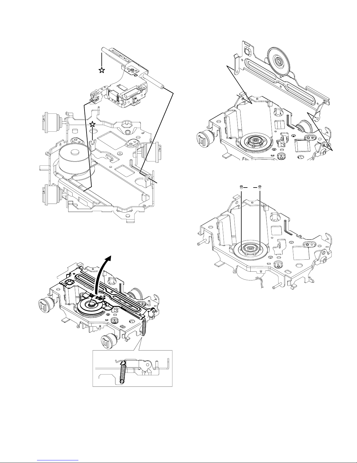
(2) Remove the shaft from the TM base. (See Fig.7)
(3) Disengage the hook on the pickup from the TM base. (See
Fig.7)
shaft
(2) Remove the HC CL. base from the holes on the TM base.
(See Fig.9)
Fig.9
(3) Remove the two screws D attaching the spindle motor.
(See Fig.10)
D
Fig.7
3.2.4 Removing the Spindle motor (See Fig.8. 9)
(1) Remove the HC CL. Spring from the HC CL. base and the
TM base, and then lift up the HC CL. base. (See Fig.8)
HC CL. spring
[ SIDE VIEW ]
Fig.8
Fig.10
(No.WA001<Rev.001>)9/18
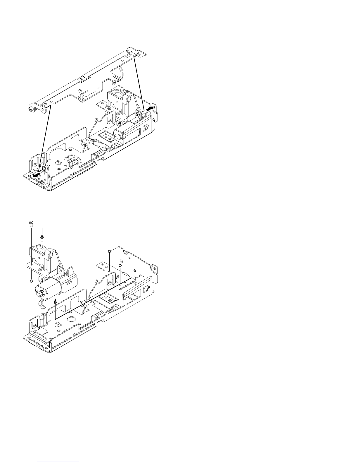
3.2.5 Removing the Loading motor
(1) Remove the roller arm assembly from the bottom frame as-
sembly. (See Fig.11)
Fig.11
(2) Remove the two screws E attaching the loading motor as-
sembly, and then remove the loading motor assembly in
the direction of the arrow. (See Fig.12)
E
Fig.12
(No.WA001<Rev.001>)10/18
4.1 TEST MODE
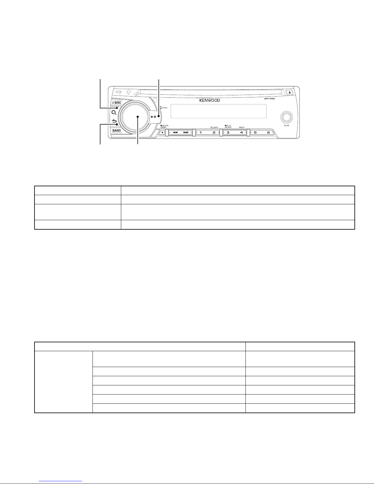
4.1.1 Panel
SEARCH
SECTION 4
ADJUSTMENT
ACCENT
KDC-152
RETURN
A symbol "" in the key column indicates that the key should be pressed and held for 1 second or longer.
4.1.2 How to enter each Test Mode
Test Mode name Operation
Production Test Mode Press and hold [1] key and [3] key and reset.
Service Test Mode
DC Error Information Mode Press and hold [3] key and [6] key and reset.
∗Transition to Test Mode shall be available during DC Error detection.
4.1.3 How to release each Test Mode
• Reset
• Momentary voltage drop
• ACC OFF
• POWER OFF
• Panel Detach
4.1.4 Production Test Mode
Press and hold [1] key and [3] key and reset.
VOL
In the STANDBY source, while pressing and holding [2] key, press [6] key for 7 seconds.
(Starting to press [2] key and [6] key at the same time can not be entered into the mode)
zDefault status immediately after the mode activation
It shall be same as normal RST start in other settings than the following.
Period to prohibit TEL/LINE MUTE immediately after activation
(normally 10seconds)
Mecha Initialize Action Prohibited
Difference in action
Write-in to E2PROM when detecting a DC error Prohibited
Demo Mode ON/OFF Setting Menu Prohibited
Power supply during ACC OFF (Back Up On) MUTE terminal turns OFF after 2 seconds
BEEP sound Beep with short-pressing in any functions
Details
1 second
(No.WA001<Rev.001>)11/18
Volume 30 (-10dB)
BASS BOOST OFF
EQ NATURAL
Various setting value
Fader/Balance Center
DEMO Mode Setting OFF
AUX Setting ON
NAVI MUTE Setting for Japan Detecting function valid (ATT)
zMode structure
Some Test Modes change according to the current source.
The following table shows the current source in Set and the related test mode status.
Model source Test mode
POWER OFF -
Standby STANDBY Test Mode
TUNER UNER Test Mode
CD CD Test Mode
AUX -
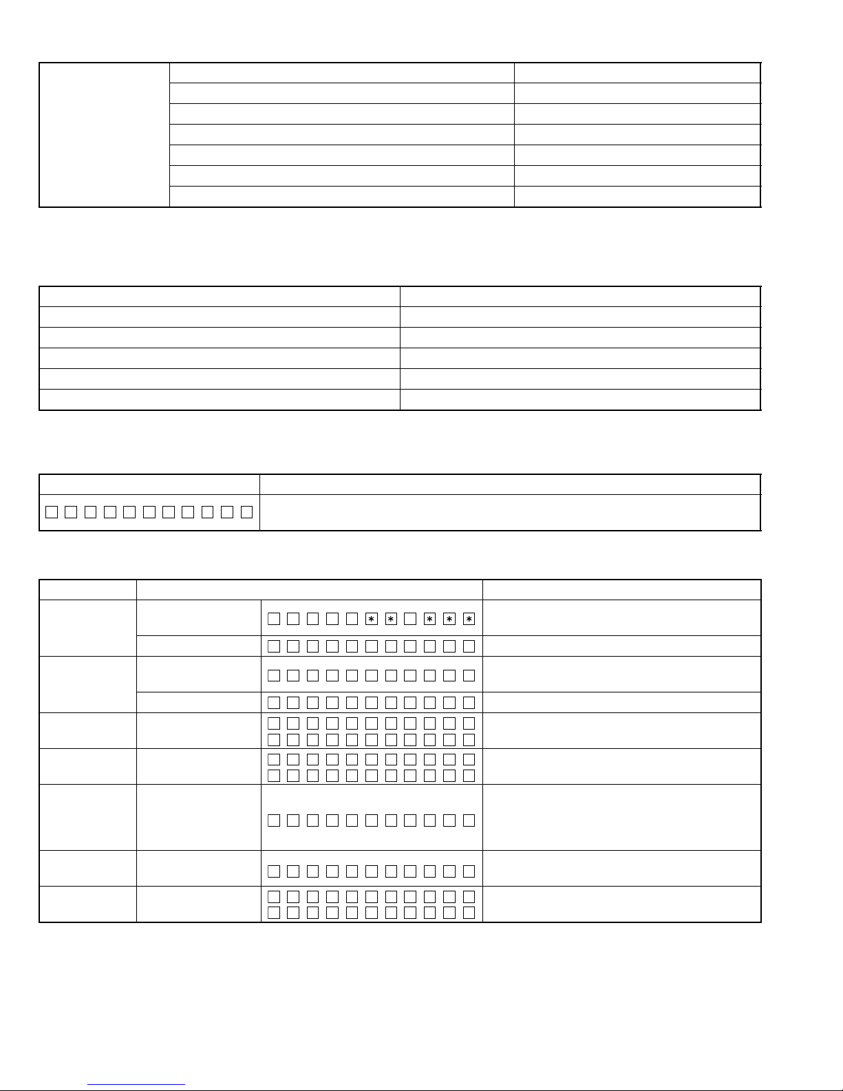
zMode content
Syscom shall display the following information after entering this mode. The operation shown below shall be workable.
Display content Details
PRO T TES
The display is released when another operation is executed.
The display will blink if sub clock is not functioning.
zSTANDBY Test Mode Specification
Operation Display content Details
1 (Toggle)
Syscom version
display
Y–SS
Syscom version (Refer to Syscom Version Table)
All lights ON All lights ON (Switch with other display)
Serial No. display (8-digit)
∗Display as it is in hex
2 (Toggle)
Serial No. display
SN 00000000
All lights ON All lights ON (Switch with other display)
3 (Toggle) All lights ON/OFF All lights ON/OFF with toggle
5 (Toggle) Preout switch Switch Preout with toggle
SWP R R REEA
SWP R S –EUBW
All lights ON → All lights OFF → odd terminal and
6
FL display short
check
even terminal of the largest grid ON alternatively
every 125ms → odd terminal ON → even terminal
ON → (repeat continuously)
SOURCE
transition
RETURN
(Toggle)
Mode release Return to Normal mode
All lights ON/OFF All lights ON/OFF with toggle
(No.WA001<Rev.001>)12/18
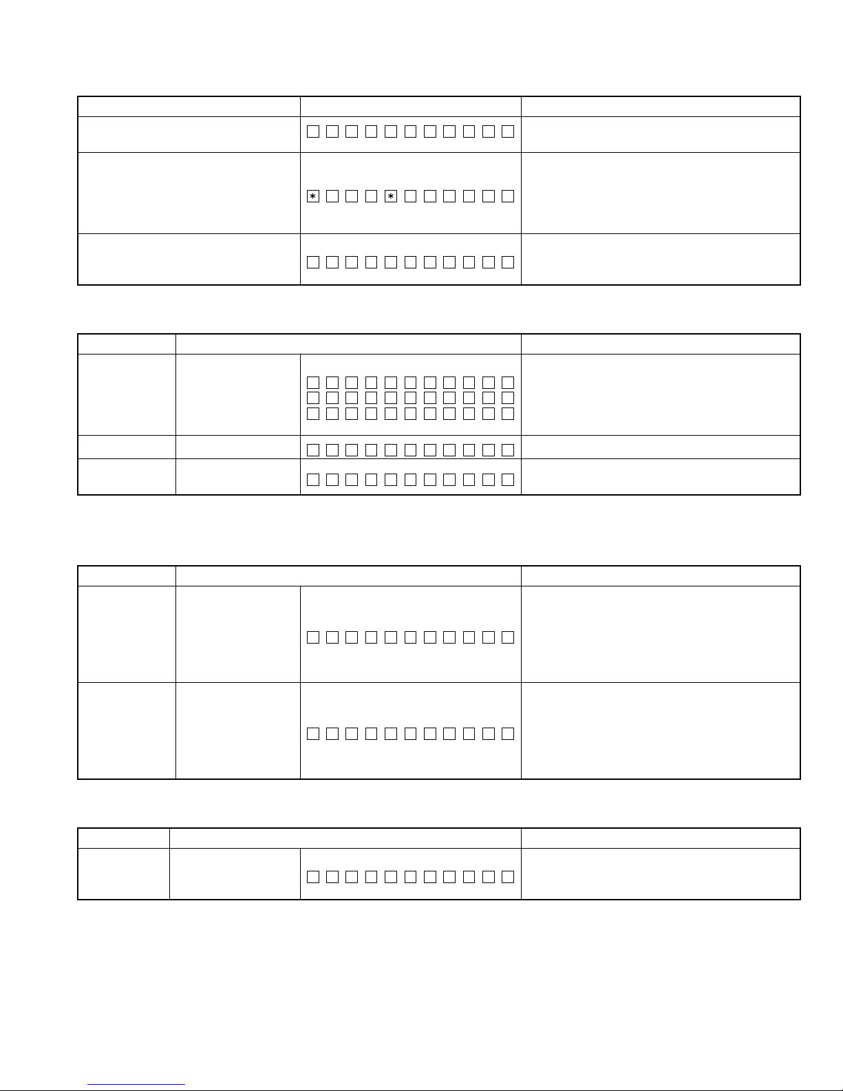
zTuner Test Mode Specification
The following display shall be indicated according to the TUNER status.
Status Display content Details
TUNER IC Normal Error
TUN CON NG
Communication to TUNER IC not available (indicated unless the mode is in Clock Display Mode).
For models that TUNER adjustment is necessary
but not done (adjustment value: 0x00 or 0xFF), the
Adjustment not implemented
ERR A A979
following TUNER Test Mode functions are valid
(“∗ERR∗”display is continuing).
Display “∗ERR∗“ blinks with 250ms interval.
Turn OFF P-CON forcibly if PS=RDS TEST is re-
RDS Specified data reception
DRS STTE
ceived.
P-CON recovers with Power OFF/ON.
Operations
Operation Display content Details
S meter value xx: Current S meter value
Determination result
OK: Within S meter voltage spec
NG: Out of S meter voltage spec
SEARCH
S meter voltage judgment display
MS– T x:xORK
MS– T x:xNRG
MS– T x:x–R–
- - : No LEVEL OFFSET adjustment
ACCENT
BAND
TUNER IC display Display TUNER IC version
BAND switch
operation
TAOM DSR
MF1–3 799AA
Execute Band Switch as shown in the following table every time Band key is pressed in each type.
TUNER Setting Adjustment Mode
1. Operation
Operation Display content Details
Shift to TUNER setting mode after switching to
98.3MHz
DISP
Shift to TUNER
setting mode
SG setting values
Frequency: 98.3MHz, Modulation frequency:
1kHz, Modulation mode: MONO, Modulation:
OFF, Deviation: 40kHz, ANT input level: 34dBpV
Select TUNER adjustment method (AUTO) using
BAND key.
BAND
(Toggle)
AUTO Adjustment
Mode
SA– –xxxLx
S-xx: Current S meter value (Hex)
L-xx: Level offset value (Hex)
∗
In case that the level offset value is not adjusted
(0xFF or 0x00), display "- -".
2. Operation in AUTO Adjustment Mode
Operation Display content Details
Start adjustment (Start Auto adjustment, and tran-
VOL PUSH Adjustment start
SA– –xxxLx
sit to Success/Failure display depending on the
adjustment result)
(No.WA001<Rev.001>)13/18
 Loading...