


Razor™ Plus 24D-26D-28D |
|
Razor™ Plus 24C-28C |
|
INSTRUCTIONS FOR USE |
|
KENT model: |
|
908 7041 020 |
- 908 7038 020 - 908 7039 020 |
908 7042 020 |
- 908 7040 020 |
INSTRUCTIONS D’UTILISATION |
|
Modèle KENT: |
|
908 7041 020 |
- 908 7038 020 - 908 7039 020 |
908 7042 020 |
- 908 7040 020 |
INSTRUCCIONES DE USO |
|
Modelo KENT: |
|
908 7041 020 |
- 908 7038 020 - 908 7039 020 |
908 7042 020 |
- 908 7040 020 |
INSTRUÇÕES DE USO |
|
Modelo KENT: |
|
908 7041 020 |
- 908 7038 020 - 908 7039 020 |
908 7042 020 |
- 908 7040 020 |
|
909 5428 000(2)2005-01 |

B |
|
|
7 |
D |
|
|
|
|
|
|
1 |
|
4 |
8 |
|
|
|
||
|
|
|
|
|
|
|
|
|
9 |
|
|
|
|
9a |
|
|
|
|
9b |
|
|
|
|
9c |
|
|
|
ECO |
|
|
|
|
|
10 |
|
|
|
5 |
6 |
|
|
|
|
|
|
|
2 |
3 |
|
|
|
|
S310170 |
|
|
|
|
|
|
C |
|
|
|
|
S310172
E
S310250 |
S310251 |
|
Razor™ Plus 24D-26D-28D / Razor™ Plus 24C-28C — 909 5428 000(2)2005-01

INSTRUCTIONS FOR USE |
|
INTRODUCTION ................................................................................................................................... |
2 |
MANUAL PURPOSE AND CONTENTS ........................................................................................................... |
2 |
TARGET ........................................................................................................................................................... |
2 |
HOW TO KEEP THIS MANUAL ....................................................................................................................... |
2 |
IDENTIFICATION DATA ................................................................................................................................... |
2 |
OTHER REFERENCE MANUALS .................................................................................................................... |
2 |
SPARE PARTS AND MAINTENANCE ............................................................................................................. |
2 |
CHANGES AND IMPROVEMENTS ................................................................................................................. |
2 |
SAFETY ................................................................................................................................................. |
2 |
SYMBOLS ......................................................................................................................................................... |
2 |
GENERAL INSTRUCTIONS ............................................................................................................................. |
2 |
UNPACKING ......................................................................................................................................... |
3 |
MACHINE DESCRIPTION ..................................................................................................................... |
3 |
AUTOMATIC SCRUBBER OPERATION CAPABILITIES ................................................................................ |
3 |
CONVENTIONS ................................................................................................................................................ |
3 |
CONTROL PANEL DESCRIPTION .................................................................................................................. |
3 |
REAR OUTSIDE VIEW DESCRIPTION ........................................................................................................... |
4 |
UNDER COVER AND TANK EXTERIOR FRONT OVERVIEW DESCRIPTION ............................................. |
4 |
TECHNICAL DATA ........................................................................................................................................... |
5 |
WIRING DIAGRAMS ........................................................................................................................................ |
6 |
ELECTRICAL FUSES ....................................................................................................................................... |
6 |
ACCESSORIES/OPTIONS ............................................................................................................................... |
6 |
USE ........................................................................................................................................................ |
6 |
BATTERY CHECK/SETTING ON A NEW MACHINE ...................................................................................... |
6 |
(WET OR GEL) BATTERY INSTALLATION AND SETTING ............................................................................ |
7 |
BEFORE MACHINE START-UP ....................................................................................................................... |
8 |
DECK INSTALLATION/REPLACEMENT ......................................................................................................... |
8 |
MACHINE START AND STOP ......................................................................................................................... |
9 |
MACHINE OPERATION ................................................................................................................................... |
9 |
TANK EMPTYING ........................................................................................................................................... |
10 |
AFTER USING THE MACHINE ...................................................................................................................... |
11 |
PUSHING/TOWING THE MACHINE .............................................................................................................. |
11 |
MACHINE LONG INACTIVITY ....................................................................................................................... |
11 |
FIRST PERIOD OF USE ................................................................................................................................ |
11 |
MAINTENANCE .................................................................................................................................. |
11 |
SCHEDULED MAINTENANCE TABLE .......................................................................................................... |
12 |
SQUEEGEE CLEANING ................................................................................................................................ |
12 |
SQUEEGEE BLADE CHECK (AND REPLACEMENT) .................................................................................. |
13 |
BRUSH/CYLINDRICAL BRUSH CLEANING .................................................................................................. |
13 |
TANK, VACUUM GRID WITH FLOAT AND RECOVERY WATER RECIRCULATION FILTER CLEANING |
|
(OPTIONAL) ................................................................................................................................................... |
13 |
SOLUTION FILTER CLEANING ..................................................................................................................... |
14 |
CHARGING THE BATTERIES ....................................................................................................................... |
14 |
FUSE CHECK/REPLACEMENT ..................................................................................................................... |
14 |
DISASSEMBLY/ASSEMBLY OF THE BRUSH-HOLDER/PAD-HOLDER DECK OR CYLINDRICAL |
|
BRUSH-HOLDER DECK ................................................................................................................................ |
15 |
SAFETY FUNCTIONS ......................................................................................................................... |
15 |
TROUBLESHOOTING ........................................................................................................................ |
15 |
SCRAPPING ........................................................................................................................................ |
16 |
Razor™ Plus 24D-26D-28D / Razor™ Plus 24C-28C — 909 5428 000(2)2005-01 |
1 |
 INSTRUCTIONS FOR USE
INTRODUCTION
MANUAL PURPOSE AND CONTENTS
The purpose of this manual is to provide the operator with all necessary information to use the machine properly in a safe and autonomous way. It contains information about technical characteristics, operation, machine storage, maintenance, spare parts and safety conditions.
Before carrying out any procedure on the machine, the operators and technicians in charge of the maintenance must read this manual carefully. Contact an authorized Kent Service Center in case of doubts regarding the interpretation of the instructions and for any further information.
SAFETY
The following symbols indicate potentially dangerous situations. Always read this information carefully and take all necessary precautions to safeguard people and property. The machine Operator's cooperation is essential in order to prevent injury. No accident prevention program is effective without the total cooperation of the person responsible for the machine operation. Most of the accidents that may occur in a factory, while working or moving around, are caused by failure to comply with the simplest rules for exercising prudence. A careful and prudent Operator is the best guarantee against accidents and is essential for successful completion of any prevention program.
TARGET
This manual is intended as a guide for the operator and the technicians qualified to perform the machine maintenance. The operators must not carry out operations reserved for qualified technicians. Kent will not be answerable for damages coming from the non-observance of this prohibition.
HOW TO KEEP THIS MANUAL
The Instructions for Use Manual must be kept near the machine, inside an adequate case, away from liquids and other substances that can cause damage to it.
IDENTIFICATION DATA
The machine model and serial number are marked on the plate on the tank and can be read from the outside (1, Fig. C). The machine model year is shown after the Date Code on the serial plate (A05 means January 2005).
This information is useful when requiring machine spare parts. Use the following table to write down the machine identification data for any further reference.
SYMBOLS
DANGER!
It indicates a dangerous situation with risk of death for the Operator.
WARNING!
It indicates a potential risk of injury for people.
CAUTION!
It indicates a caution related to important or useful functions. Pay attention to the paragraphs marked by this symbol.
NOTE
Refer to the manual before performing any operation.
MACHINE model .............................................................
MACHINE serial number .................................................
OTHER REFERENCE MANUALS
Electronic Battery Charger Manual, which is to be considered an integral part of this Manual.
Moreover, the following manuals are available:
–Service Manual, that can be consulted at Kent Service Centers.
–Spare Parts List, supplied with the machine.
SPARE PARTS AND MAINTENANCE
All necessary operating, maintenance and repair procedures must be carried out by qualified personnel or by Kent Service Centers. Only original spare parts and accessories must be used.
Call Kent for service or to order spare parts and accessories, specifying the machine model and serial number.
CHANGES AND IMPROVEMENTS
Kent constantly improves its products and reserves the right to make changes and improvements at its discretion without being obliged to apply such benefits to the machines that were previously sold.
Any change and/or addition of accessory must be approved and performed by Kent.
GENERAL INSTRUCTIONS
Description of potential risk of damages to people and machine.
DANGER!
–Before performing any maintenance/repair operation, disconnect the battery.
–This machine must be used by properly trained and authorized personnel only. Children or disabled people cannot use this machine.
–Keep the battery far from sparks, flames and incandescent material. During the normal operation explosive gases are released.
–Do not wear jewelry when working near electrical components.
–Do not work under the lifted machine without support it with safety stands.
–Do not operate the machine near toxic, dangerous, inflammable and/or explosive powders, liquids or vapors.
–Battery charging produces highly explosive hydrogen gas. Keep the tanks open during battery charging and perform this operation in well-ventilated areas and away from naked flames.
2 |
Razor™ Plus 24D-26D-28D / Razor™ Plus 24C-28C — 909 5428 000(2)2005-01 |

INSTRUCTIONS FOR USE 
WARNING!
–Carefully read all the instructions before carrying out any maintenance/repair operations.
–Before using the battery charger, ensure that frequency and voltage values, indicated on the machine serial number plate, match the mains voltage.
–Take all necessary precautions to prevent hair, jewelry and loose clothes from being caught in the moving parts.
–Do not smoke while charging the batteries.
–Do not leave the machine unattended without being sure that the machine cannot move independently.
–Do not wash the machine with direct or pressurized water jets, or with corrosive substances.
–Do not use the machine in particularly dusty areas.
–While using this machine, take care not to cause damage to other people, especially children.
–Do not put any can containing fluids on the machine.
–The storage temperature must be between +32°F and +104°F (0°C and +40°C).
–The machine operating temperature must be between +32°F and +104°F (0°C and +40°C).
–The humidity must be between 30% and 95%.
–Always protect the machine against the sun, rain and bad weather, both under operation and inactivity condition.
–Do not use the machine as a means of transport.
–Do not use the machine on slopes with an inclination higher than 2%.
–Do not allow the brushes to operate while the machine is stationary to avoid damaging the floor.
–In case of fire, possibly use a powder fire extinguisher, not a water one.
–Do not bump into shelves or scaffoldings, particularly where there is a risk of falling objects.
–Do not tamper with the machine safety guards and follow the ordinary maintenance instructions scrupulously.
–Do not remove or modify the plates affixed to the machine.
–In case of machine malfunctions, ensure that these are not due to lack of maintenance. Otherwise, request assistance from the authorized personnel or from an authorized Service Center.
–If parts must be replaced, require ORIGINAL spare parts from a Dealer or Authorized Retailer.
–To ensure the proper and safe operation of the machine, have the scheduled maintenance, detailed in the related chapter of this manual, performed by the authorized personnel or an authorized Service Center.
–The machine must be disposed of properly, because of the presence of toxic-harmful materials (batteries, etc.), which are subject to standards that require disposal in special centres (see the Scrapping chapter).
–If the machine is used according to the instructions, the
vibrations do not cause dangerous situations. The machine vibration level is less than 2.5 m/s2.
–Do not leave any object penetrate in the openings. Do not use the machine in case the openings are clogged; always keep the openings free from dust, hairs and any other foreign material which could reduce the air flow.
–This machine cannot be used on public roads.
–Pay attention during the machine transfers when temperature is below freezing point. The water in the recovery tank or in the hoses could freeze and seriously damage the machine.
–Use only brushes and the pad-holders supplied with the machine and those specified in the Instructions for Use manuals. Using other brushes or pad-holders could reduce safety.
UNPACKING
When the machine is delivered, check that the packing and the machine were not damaged during transportation. In case of visible damages, keep the packing and have it checked by the Carrier that delivered it. Call the Carrier immediately to fill in a damage claim.
Please check that the following items have been supplied with the machine:
1.Technical documents:
–Automatic Scrubber Instructions for Use Manual
–Electronic Battery Charger Manual
–Automatic Scrubber Spare Parts List
2.No. 2 lamellar fuses
3.No. 5 6V battery housing shims
MACHINE DESCRIPTION
AUTOMATIC SCRUBBER OPERATION CAPABILITIES
The Automatic Scrubber is used to clean (scrubbing and drying) smooth and solid floors, in civil or industrial environment, under safe operation conditions by a qualified Operator.
The Automatic Scrubber cannot be used for fitted carpet and carpet washing.
CONVENTIONS
Forward, backward, front, rear, left or right are intended with reference to the Operator position, that is to say with the hands on the handlebar (2, Fig. C).
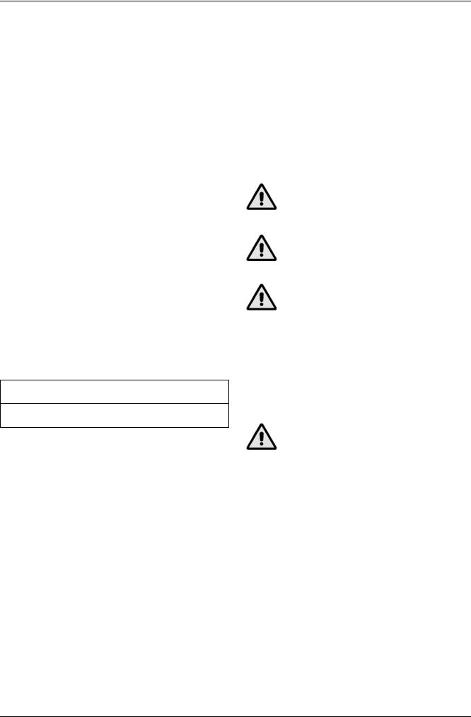
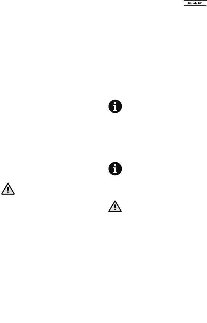
CONTROL PANEL DESCRIPTION
(See Fig. B)
1.Control panel
2.Brush/pad/cylindrical brush-holder deck lifting/lowering switch
3.Brush or pad extra pressure switch (deactivated when the cylindrical brush-holder deck is installed)
4.Solution flow control lever
5.Solution flow control lever “ECO” position (water “economy” usage, for a washing autonomy of 70 minutes approximately)
6.Brush or pad-holder release switch
7.Forward/reverse speed adjuster
8.Hour counter
9.Battery charge indicator
9a. Green warning light (ON: charged batteries)
9b. Yellow warning light (ON: nearly discharged batteries)
9c. Red warning light (ON: discharged batteries)
10. Ignition key (0 - I)
Razor™ Plus 24D-26D-28D / Razor™ Plus 24C-28C — 909 5428 000(2)2005-01 |
3 |

 INSTRUCTIONS FOR USE
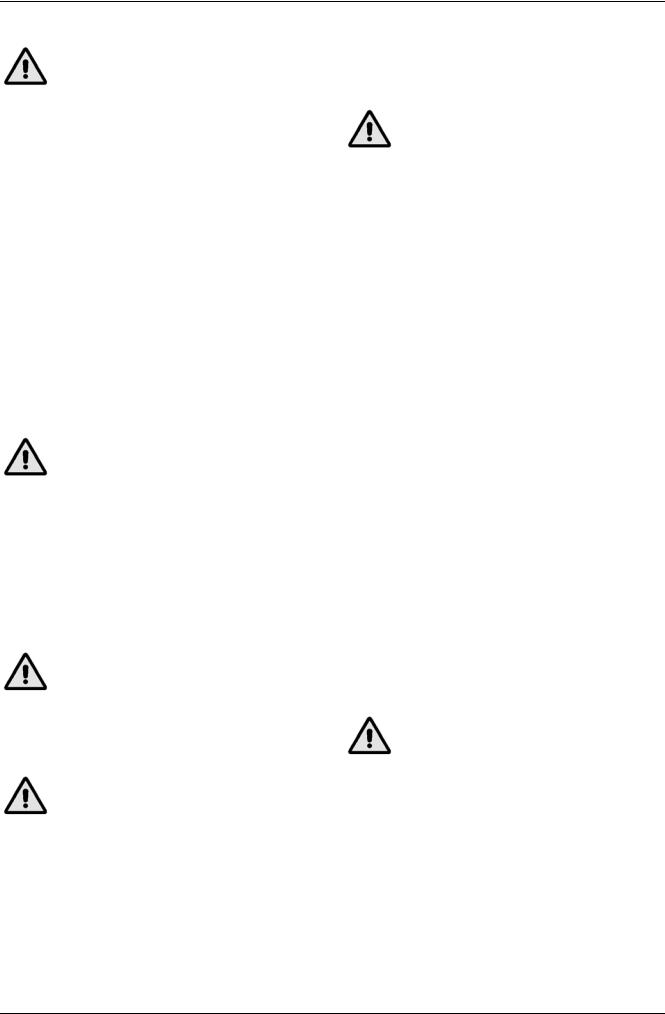
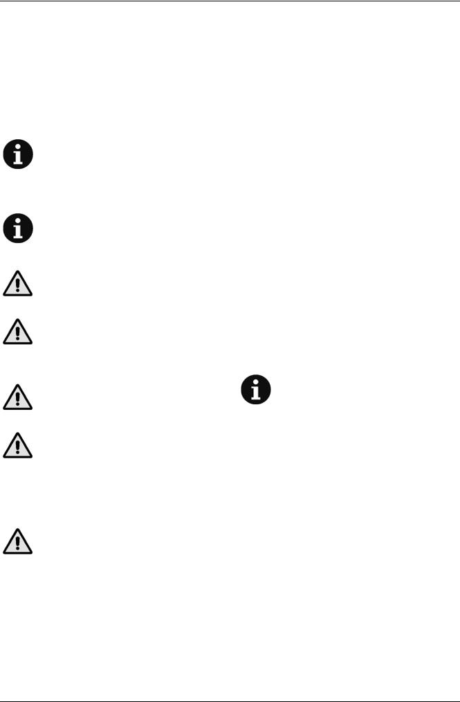
REAR OUTSIDE VIEW DESCRIPTION
(See Fig. C)
1.Serial number plate/technical data
2.Machine handlebar
3.Handlebar inclination adjusting knobs
4.Paddle for forward/reverse gear activation and brush/pad-holder rotation
5.Can holder
6.Pocket
7.Tank cover
8.Rear steering wheel
9.Front wheels on fixed axle
10.Wheel cover
11.Brush/pad
12.Brush-holder/pad-holder deck
13a. Brush-holder/pad-holder deck front spoiler
13b. Cylindrical brush-holder deck front spoiler
14.Cylindrical brushes
15.Cylindrical brush-holder deck
16.Squeegee
17.Squeegee fixing handwheels
18.Squeegee balance adjusting handwheel
19.Front squeegee blade
20.Rear squeegee blade
21.Squeegee rear blade fastening hook
22.Squeegee front blade fixing wing nuts
23.Squeegee rear blade fixing wing nuts
24.Squeegee vacuum hose
25.Squeegee lifting/lowering lever
26.Recovery water drain hose
27.Solution drain hose
28.Solution filter
29.Solution tap
30.Battery connector (red)
This connector also works as EMERGENCY switch, to stop immediately all functions.
31.Battery charger cable
32.Battery charger cable holder
33.Battery charger data inspection window
34.Service and parking brake lever (optional)
35.Recovery water recirculation system switch (optional)
36.Drive cut-off switch
(for pushing/towing the machine)
37.Parking brake release lever
38.Shockproof rollers
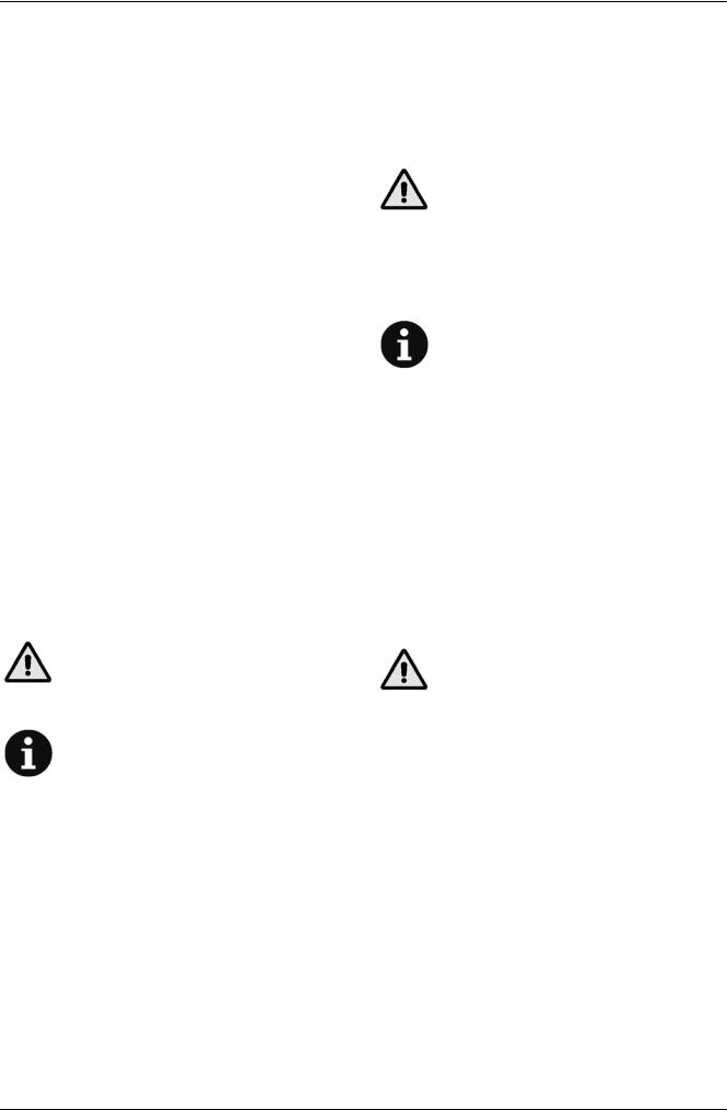
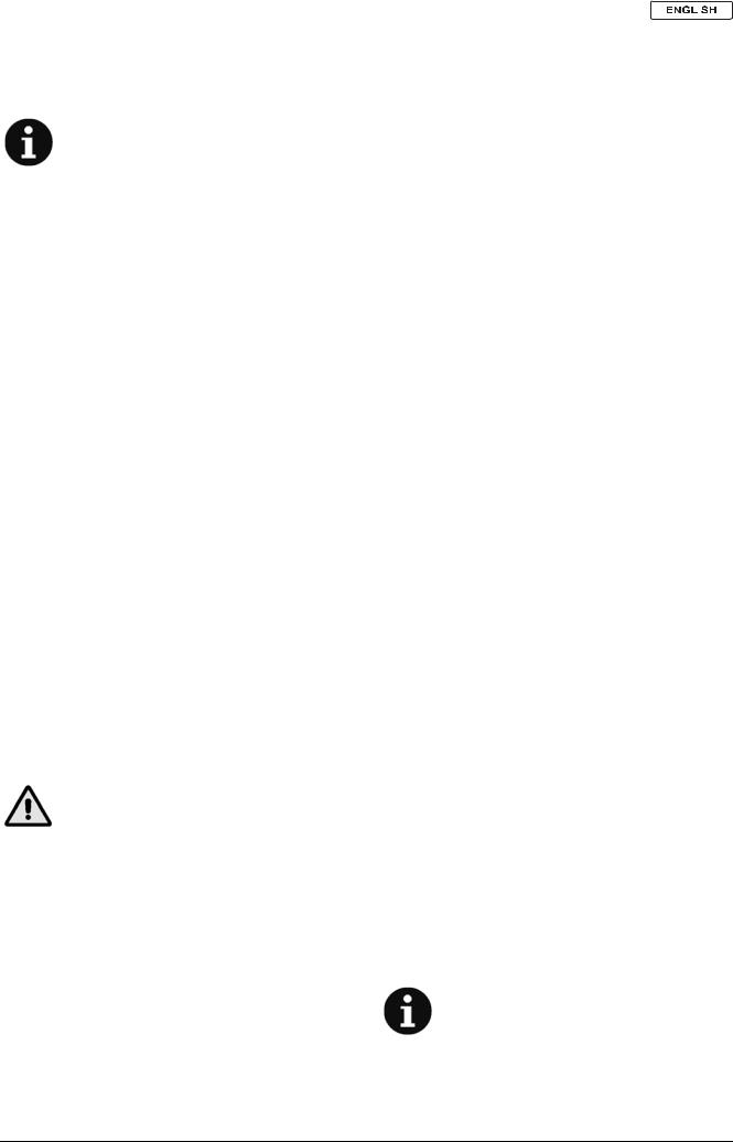
(See Fig. E)
1.Electronic battery charger
2a. Red warning light (ON: the battery is charging)
2b. Yellow warning light (ON: the battery is almost completely charged)
2c. Green warning light (ON: the battery is charged)
3.Lead (WET) or gel (GEL) battery selector on the electronic battery charger
4.Lead (WET) or gel (GEL) battery selector on the function electronic board
5.Drive electronic board
6.Function electronic board
7.Drive electronic board fuse
8.Function electronic board fuse
9.Electrical component cover
10.Cover gasket
11.Rubber protection panel
12.Battery connection connector
13.Battery charger cable
14.Battery charger cable holder
15.Squeegee lifting/lowering lever handle
16.Cover fixing nuts
17.Vacuum system automatic deactivation selector
UNDER COVER AND TANK EXTERIOR FRONT OVERVIEW DESCRIPTION
(See Fig. G)
1.Tank cover (open)
2.Tank cover gasket
3.Compensation hole
4.Solution tank
5.Recovery water tank
6.Solution feed hose (extractible)
7.Vacuum grid with automatic float shut-off system
8.Recovery water recirculation system filter (optional)
9.Recovery water recirculation system float (optional)
10.Tank cover gasket seat
11.Tank cover gasket junction
12.Gasket seating surface
13.Retainer
14.Float
15.Solution tank shield
16.Plug for vacuum duct cleaning
(See Fig. J)
1.Solution drain hose
2.Solution level marks
3.Tank assembly release handwheel
4.Tank assembly (lifted position)
5.Vacuum motor gasket
6.Battery assembly diagrams
7.Battery compartment
8.Batteries
9.Battery caps
10.Vacuum motor
11.Brush/pad-holder motor connector
12.Brush-holder/pad-holder deck
13.Splash-shield
14.Brush-holder/pad-holder deck front spoiler
15.Brush
16.Pad-holder
17.Pad
18.Brush/pad-holders motors
19.Brush-holder/pad-holder/cylindrical brush-holder deck cotter pins
20.Brush-holder/pad-holder/cylindrical brush-holder deck fixing handwheel
21.Brush/cylindrical brush solution hose
22.Cylindrical brush-holder deck
23.Cylindrical brushes
24.Cylindrical brush lids
25.Cylindrical brush lid fixing handwheels
26.Cylindrical brush debris container
27.Debris container handle
28.Cylindrical brush motors
29.Cylindrical brush-holder deck front spoiler
4 |
Razor™ Plus 24D-26D-28D / Razor™ Plus 24C-28C — 909 5428 000(2)2005-01 |

|
|
INSTRUCTIONS FOR USE |
|
|
||||||
|
|
|||||||||
|
|
|||||||||
TECHNICAL DATA |
|
|
|
|
|
|
|
|
|
|
|
|
|
|
|
|
|
|
|
|
|
|
General technical characteristics |
|
|
|
|
|
|
|
|
|
|
|
|
|
|
|
|
|
|||
Dimensions |
|
Razor™ Plus 24D |
|
Razor™ Plus 26D |
|
Razor™ Plus 28D |
||||
|
|
|
|
|
|
|
|
|||
Cleaning width |
|
24.0in (610 mm) |
|
26.0 in (660 mm) |
|
29.1 in (740 mm) |
||||
|
|
|
|
|
|
|
|
|||
Squeegee width |
|
32.0 in (812 mm) |
|
|
34.0 in (860 mm) |
|||||
|
|
|
|
|
|
|
|
|
|
|
Machine height |
|
|
|
42.0 in (1,065 mm) |
|
|
|
|
||
|
|
|
|
|
|
|
|
|
|
|
Solution tank capacity |
|
|
|
21 gal (80 liters) |
|
|
|
|
||
|
|
|
|
|
|
|
|
|
|
|
Dirty water tank capacity |
|
|
|
21 gal (80 liters) |
|
|
|
|
||
|
|
|
|
|
|
|
|
|
|
|
Front wheels diameter |
|
|
|
10.5 in (267 mm) |
|
|
|
|
||
|
|
|
|
|
|
|||||
Front wheel specific pressure on the ground |
|
|
|
Less than 0.5 N/mm2 |
||||||
Rear wheels diameter |
|
|
|
3.9 in (100 mm) |
|
|
|
|
||
|
|
|
|
|
|
|
|
|
|
|
Vacuum motor power |
|
|
|
0.68 HP (500 W) |
|
|
|
|
||
|
|
|
|
|
|
|
|
|
|
|
Drive motor power |
|
|
|
0.27 HP (200 W) |
|
|
|
|
||
|
|
|
|
|
||||||
Drive speed (variable) |
|
|
0 to 3.2 mph (0 to 5.2 km/h) |
|||||||
|
|
|
|
|
|
|
|
|
|
|
Gradeability |
|
|
2% |
|
|
|
|
|
||
|
|
|
|
|
|
|
|
|
|
|
Sound pressure level (at the Operator's position) |
|
|
|
65 dBA |
|
|
|
|
||
|
|
|
|
|||||||
Standard batteries (with case) |
|
24V 195 Ah (wet) / 24V 238 Ah (wet) |
||||||||
|
|
|
|
|||||||
Battery compartment dimensions (with case) |
|
20.8 x 15.0 in, height 14.7 in (530 x 380 mm, height 375 mm) |
||||||||
|
|
|
|
|
||||||
Vacuum system capacity |
|
|
59.8 inH2O (1,520 mmH2O) |
|||||||
|
|
|
|
|
|
|
||||
Technical data for machines with brush-holder/pad-holder deck |
|
|
|
|
|
|||||
|
|
|
|
|
|
|
|
|||
Dimensions |
|
Razor™ Plus 24D |
|
Razor™ Plus 26D |
|
Razor™ Plus 28D |
||||
|
|
|
|
|
|
|
|
|||
Machine maximum length |
|
57.8 in (1,470 mm) |
|
57.9 in (1,473 mm) |
|
58.6 in (1,489 mm) |
||||
|
|
|
|
|
|
|
|
|||
Machine width without squeegee |
|
25.3 in (645 mm) |
|
26.3 in (669 mm) |
|
29.4 in (748 mm) |
||||
|
|
|
|
|
|
|
|
|||
Brush diameter |
|
12.0 in (305 mm) |
|
13.0 in (330 mm) |
|
14.5 in (370 mm) |
||||
|
|
|
|
|
|
|
|
|
|
|
Weight without batteries and with empty tanks |
|
|
|
308 lb (140 Kg) |
|
|
|
|
||
|
|
|
|
|
|
|
|
|
|
|
Maximum weight with batteries and full tanks |
|
|
|
842 lb (382 Kg) |
|
|
|
|
||
|
|
|
|
|
|
|
|
|
|
|
Brush motor power |
|
|
|
0.54 HP (400 W) |
|
|
|
|
||
|
|
|
|
|
|
|
|
|
|
|
Brush rotation speed (variable) |
|
|
|
0 to 220 rpm |
|
|
|
|
||
|
|
|
|
|||||||
Brush pressure |
|
66 to 110 lb (30 to 50 Kg) with gas spring |
||||||||
|
|
|
|
|
|
|
|
|||
|
|
|
|
|
|
|
||||
Technical data for machines with cylindrical brush-holder deck |
|
|
|
|
|
|||||
|
|
|
|
|
||||||
Dimensions |
|
Razor™ Plus 24C |
|
Razor™ Plus 28C |
||||||
|
|
|
|
|
|
|
|
|
|
|
Machine maximum length |
|
|
|
57.4 in (1,460 mm) |
|
|
|
|
||
|
|
|
|
|
||||||
Machine width without squeegee |
|
26.7 in (680 mm) |
|
|
30.7 in (780 mm) |
|||||
|
|
|
|
|
||||||
Cylindrical brush size (diameter x length) |
|
5.7 x 23.2 in (145 x 590 mm) |
|
5.7 x 27.1 in (145 x 690 mm) |
||||||
|
|
|
|
|
|
|
|
|
|
|
Weight without batteries and with empty tanks |
|
|
|
308 lb (140 Kg) |
|
|
|
|
||
|
|
|
|
|
|
|
|
|
||
Maximum weight with batteries and full tanks |
|
|
|
842 lb (382 Kg) |
|
|
|
|
||
|
|
|
|
|
||||||
Brush motor power |
|
0.54 HP (400 W) |
|
|
0.81 HP (600 W) |
|||||
|
|
|
|
|
|
|
|
|
||
Cylindrical brush rotation speed |
|
545 rpm |
|
|
|
|
|
613 rpm |
||
|
|
|
|
|
|
|||||
Cylindrical brush pressure |
|
67.1 lb (30.5 Kg) |
|
|
73.5 lb (33.4 Kg) |
|||||
|
|
|
|
|
|
|
|
|
|
|
Razor™ Plus 24D-26D-28D / Razor™ Plus 24C-28C — 909 5428 000(2)2005-01 |
5 |

 INSTRUCTIONS FOR USE
WIRING DIAGRAMS |
ACCESSORIES/OPTIONS |
(See Fig. K)
BAT |
Battery 24V |
C1 |
Battery connector |
C2 |
Battery charger signal connector |
CH |
Battery charger 24V 25A |
EB1 |
Function electronic board |
EB2 |
Drive electronic board |
EB3 |
Electronic board LED |
EV1 |
Water solenoid valve |
EV2 |
Recirculation solenoid valve (optional) |
F1 |
Function electronic board fuse |
F2 |
Drive electronic board fuse |
HM |
Hour counter |
K1 |
Key switch |
LD1 |
Brush switch warning light |
LD2 |
Extra pressure warning light |
M1 |
Left brush motor |
M2 |
Right brush motor |
M3 |
Vacuum motor |
M4 |
Brush-holder deck actuator |
M5 |
Machine drive motor |
M6 |
Water recirculation pump (optional) |
R1 |
Machine drive speed potentiometer |
R2 |
Machine drive maximum speed potentiometer |
SW1 |
Brush switch |
SW2 |
Extra pressure switch |
SW3 |
Vacuum micro-switch |
SW4 |
Brush release switch |
SW5 |
Brush enabling micro-switch |
SW6 |
Actuator position 0 micro-switch |
SW7 |
Actuator position 1 micro-switch |
SW8 |
Actuator position 2 micro-switch |
SW9 |
Drive enabling micro-switch |
SW10 |
Drive motor release switch |
SW11 |
Water recirculation control switch (optional) |
SW12 |
Water recirculation float switch (optional) |
Color code
BK |
Black |
BU |
Blue |
BN |
Brown |
GN |
Green |
GY |
Grey |
OG |
Orange |
PK |
Pink |
RD |
Red |
VT |
Violet |
WH |
White |
YE |
Yellow |
ELECTRICAL FUSES
Fuses
–Function electronic board fuse (100A) (7, Fig. E)
–Drive electronic board fuse (30A) (8, Fig. E)
In addition to the standard components, the machine can be equipped with the following accessories/options, according the machine specific use:
1.Gel batteries
2.Brushes of materials different from the standard ones
3.Pads of different materials
4.Squeegee oil-proof blades
5.Recovery water recirculation system
6.Service and parking brake
7.Front wheels and rear wheel of different materials
8.Shockproof rollers, oversize
For further information concerning the optional accessories, contact an authorized Retailer.
USE
WARNING!
On some points of the machine there are some adhesive plates indicating:
-DANGER
-WARNING
-CAUTION
-NOTE
While reading this manual, the Operator must pay particular attention to these symbols.
Do not cover these plates for any reason and immediately replace them if they are damaged.
BATTERY CHECK/SETTING ON A NEW MACHINE
WARNING!
The electric components of this machine can be seriously damaged if batteries are either installed or connected improperly. The batteries must be installed by qualified personnel only. Set the function electronic board and the battery charger according to the type of batteries used (lead or gel batteries. Check the batteries for damage before installation.
Disconnect the battery connector and the battery charger plug.
Handle the batteries with great care. Install the battery terminal protection caps supplied with the machine.
The machine can be equipped with:
–two 12V batteries
–four 6V batteries
–one 24V battery
connected according to the diagram shown in Fig. J (6).
6 |
Razor™ Plus 24D-26D-28D / Razor™ Plus 24C-28C — 909 5428 000(2)2005-01 |

INSTRUCTIONS FOR USE 
The machine can be supplied in one of the following modes: a)
(WET OR GEL) BATTERY INSTALLATION AND SETTING
1.
2.
b)
1.
2.
3.
4.
5.Fill up each battery element with sulfuric acid for batteries (density 2.8 to 2.9 lb at 77°F (1.27 to 1.29 Kg at 25°C)) in accordance with the instructions specified in the Battery manual.
The correct quantity of sulfuric acid to fill in is given in the Battery manual.
6.To avoid damaging the floor, dry with a cloth both acid and water on the top of the batteries after charge.
7.Let the batteries rest for a few minutes and fill in with sulfuric acid in accordance with the instructions specified in the Battery manual.
8.Charge the batteries (see the relevant procedure in the
Maintenance chapter).
c)Without batteries
1.Buy appropriate batteries [See the Technical Data paragraph and the installation diagram (6, Fig. J)].
For the battery choice and installation, apply to qualified battery retailers.
2.Install and set the batteries (WET or GEL) as described in the following chapter, then installed the battery charger according to the battery type.
According to the battery type (WET or GEL) perform the setting of the machine electronic board and of the battery charger, operating as indicated below:
Machine setting
1.Ensure that the battery connector (30, Fig. C) is completely disconnected.
2.Remove the handle (15, Fig. E) from the squeegee lifting/lowering lever.
3.Unscrew the nuts (16, Fig. E), carefully remove the cover (9), and move the panel (11) as necessary.
4.According to the type of batteries to be installed, move the selector (4, Fig. E) to “ON” position for lead/acid batteries, or to “OFF” position for gel batteries.
Make sure not to move the vacuum system automatic deactivation selector (17, Fig. E).
Setting of the battery charger
5.Take the battery charger selector (3, Fig. E) to “WET” position for lead batteries, or to “GEL” position for gel batteries.
6.Reinstall the panel (11, Fig. E), then reinstall the cover (9, Fig. E) again and fix it with the nuts (16).
7.Install the squeegee lifting/lowering lever handle (15, Fig. E).
Battery installation
8.Lift the cover (1, Fig. G) and make sure that the tanks (4 and 5, Fig. G) are empty, otherwise drain them through the drain hoses (26 and 27, Fig. C).
9.Turn the handwheel (3, Fig. J) counter-clockwise until the tank assembly is released.
10.Carefully lift the tank assembly (4, Fig. J) with the handlebar (2, Fig. C).
11.Install the batteries according to the diagram (6, Fig. J), and follow the indications below according to the type of batteries to be installed:
–For the two 12V batteries: Use the restraints supplied with the machine;
–For the four 6V batteries: Use the restraints supplied with the machine;
–For the 24V battery: Remove the case (7, Fig. J).
Battery charging
12.Charge the batteries (see the relevant procedure in the Maintenance chapter).
Razor™ Plus 24D-26D-28D / Razor™ Plus 24C-28C — 909 5428 000(2)2005-01 |
7 |
 INSTRUCTIONS FOR USE
BEFORE MACHINE START-UP |
Cylindrical brush installation |
WARNING!
When the machine is to be started by turning the ignition key (10, Fig. B) to “I” position, make sure that, between the deck (12 or 15, Fig. C) and the above tank assembly, there is no foreign material which may prevent the deck from lifting. This check is necessary because, if the machine has been previously turned off without the deck being deactivated (lifted position), when turned on again, the deck is automatically deactivated (lifted position).
DECK INSTALLATION/REPLACEMENT
On the machines from Serial Number 1776829, it is possible to install either a brush-holder/pad-holder deck (12, Fig. C) or a cylindrical brush-holder deck (15).
For deck installation/replacement see the procedure in the Maintenance chapter.
Brush or pad-holder installation/replacement
1.According to the kind of cleaning to be carried out, the machine can be equipped both with brushes (15, Fig. J) and pad-holders (16) with pads(17) together with the appropriate deck.
2.Insert the ignition key (10, Fig. B) and turn it to “I” position.
WARNING!
Before turning on the brush/pad-holder deck lifting/lowering switch (2, Fig. B), always check that, between the deck (12) and the above tank assembly, there is no foreign material which may prevent the deck from lifting.
3.Idle the speed adjuster (7, Fig. B) by turning it counter-clockwise.
4.Position the brushes/pad-holders under the appropriate deck (12, Fig. C).
5.Press the switch (2, Fig. B) to lower the deck (12, Fig. C).
6.Lightly press the paddle (4, Fig. C) to engage the brushes.
WARNING!
Do not press the paddle (4, Fig. C) completely, otherwise the machine will start; a light pressure on the paddle is enough to engage the brushes and activate the brush motors.
7.Press the switch (2, Fig. B) to deactivate the deck (12, Fig. C) (lifted position).
9.Insert the ignition key (10, Fig. B) and turn it to “I” position.
10.Turn on the cylindrical brush-holder deck lifting/lowering switch (2, Fig. B).
WARNING!
Before turning on the cylindrical brush-holder deck lifting/lowering switch (2, Fig. B), always check that, between the deck (15) and the above tank assembly, there is no foreign material which may prevent the deck from lifting.
11.Turn the ignition key (10, Fig. B) to “0” position and remove it.
12.Unscrew the handwheels (25, Fig. J) and remove the lids (24) by pushing them downwards and pressing on the handwheels.
13.Install the cylindrical brushes (23).
The cylindrical brushes can be installed on either sides.
14.Reinstall the lids (24, Fig. J) and fix them with the handwheels (25).
Squeegee installation
15.Install the squeegee (16, Fig. C) and fix it by means of the handwheels (17), then connect the hose (24) to the squeegee.
16.Using the handwheel (18, Fig. C), adjust the squeegee so that its rear blade (20) - in all its length - touches the floor and that the front blade (19) is slightly detached from the floor.
Solution tank filling
17.Open the tank cover (1, Fig. G).
18.Lift the shield (15, Fig. G) and, by means of the extractible hose (6), fill the solution tank (4) with the appropriate solution for the cleaning to be carried out. Do not fill the solution tank completely, leave a few centimeters from the edge.
Always follow the dilution instructions on the label of the chemical product used to create the solution.
The solution temperature must not exceed 104°F (40°C).
Using the transparent hose (1, Fig. J) and the marks (2), it is possible to check the quantity of solution in the tank. Moreover, it is possible to consult a gallon/liter table located on the inner side of the cover (1, Fig. G).
CAUTION!
Use only low-foam and non-flammable solutions, intended for automatic scrubber applications.
WARNING!
When the deck has not been lifted yet, and the warning light on the switch (2, Fig. B) is flashing, the brushes (11, Fig. C) start to turn when pressing the paddle (4, Fig. C). It is therefore important to make sure that there is nothing which can prevent the brush from rotating and that nobody is near the brushes before pressing the paddle (4, Fig. C).
8.Turn the ignition key (10, Fig. B) to “0” position and remove it.
Adjustments
19.Using the knobs (3, Fig. C), adjust the handlebar (2) to reach a comfortable position.
8 |
Razor™ Plus 24D-26D-28D / Razor™ Plus 24C-28C — 909 5428 000(2)2005-01 |
INSTRUCTIONS FOR USE 
MACHINE START AND STOP |
Stopping the machine |
Start
1.Prepare the machine as described in the previous paragraph.
2.Lower the squeegee (16, Fig. C) by means of the lever (25).
When the lever (25) is lowered, the vacuum system starts operating. When the lever (25) is lifted, the vacuum system stops after a few seconds.
3.Position the solution flow control lever (4, Fig. B) in the most appropriate position, depending on the type of cleaning to be carried out:
–“ECO” system: when the lever (4) is in the “ECO” position (5), the machine works in a special condition of programmed water “economy” usage; as the water flow is set and constant, the machine can work with a washing autonomy of 66 minutes (1.2 liters/min average).
–Variable system: if the lever is in the upper area, related to the variable flow, it is possible to have a capacity ranging from 3.8 liters/min minimum to 9.4 liters/min maximum.
In no case it is possible to close completely the water flow to the brushes during operation.
4.Insert the ignition key (10, Fig. B) and turn it to “I” position.
NOTE
If the green warning light (9a, Fig. B) turns on, the machine is ready to be used. If the yellow or red warning light (9b or 9c) turns on, it is necessary to charge the batteries (see the procedure in Maintenance chapter).
5.Lower the brush/pad/cylindrical brush-holder deck (11/14, Fig. C) by means of the switch (2, Fig. B).
NOTE
While the deck (12/15, Fig. C) is moving from the lifted position to the lowered position, the warning light on the switch (2, Fig. B) flashes; when the deck has reached the lowered position, the warning light stays on.
6.If equipped, disengage the parking brake by pulling the levers (34 and 37, Fig. C) at the same time, and then release them.
7.With a hand on the handlebar (2, Fig. C), operate the machine by pressing the paddle (4, Fig. C): the machine will start moving and the brushes/pad-holder will start rotating.
8.Operate on the speed adjuster (7, Fig. B) to change the machine speed.
9.Release the paddle (4, Fig. C).
10.Lift the brushes/pad-holder by means of the switch (2, Fig. B).
NOTE
While the deck (12/15, Fig. C) is moving from the lowered position to the lifted position, the warning light on the switch (2, Fig. B) flashes; when the deck has reached the lifted position, the warning light turns off.
11.Lift the squeegee by means of the lever (25, Fig. C).
12.Make sure that the machine cannot move independently. If equipped, engage the parking brake by pulling the lever (34, Fig. C) until it locks.
MACHINE OPERATION
1.Start the machine as described in the previous paragraph.
2.Keeping both hands on the handlebar (2, Fig. C), manoeuvre the machine and start washing/drying the floor.
3.If necessary, vary the solution quantity to the brushes by means of the lever (4, Fig. B).
4.If necessary, adjust the squeegee balance adjusting handwheel (18, Fig. C).
CAUTION!
To avoid any damage to the floor surface, stop the brushes/pad-holder rotation when the machine stops in one place, especially when the machine is working with the extra pressure function activated.
Working with brush/pad-holder extra pressure function activated
5.If the dirt on the floor proves to be particularly difficult to clean, it is possible to work with an extra pressure of the brushes/pad-holders on the floor by pressing the switch (3, Fig. B).
CAUTION!
It is not possible to activate the extra pressure function when the cylindrical brush-holder deck (15, Fig. C) is used.
6.To go back to normal pressure cleaning, press the switch
(3) again.
The switch (3, Fig. B) is active only when the deck (12, Fig. C) is lowered and the warning light on the switch (2, Fig. B) is on.
NOTE
While the deck (12, Fig. C) is moving, from the lowered position with normal pressure to the lowered position with extra pressure, the warning light on the switch (3, Fig. B) flashes. When the lowered position with extra pressure is reached, the warning light stays on.
Razor™ Plus 24D-26D-28D / Razor™ Plus 24C-28C — 909 5428 000(2)2005-01 |
9 |
 INSTRUCTIONS FOR USE
Brush overload safety system activation
7.In case of brush motor overload, due to foreign bodies which prevent the brushes/pad-holders from rotating, or to excessively aggressive floors/brushes, the safety system stops the brushes/pad-holders after about a minute of continuous overload. The overload is shown by the three warning lights (9a, 9b, 9c, Fig. B) flashing simultaneously.
If the overload takes place during a cleaning with the extra pressure function activated, the system automatically reduces the pressure on the brushes/pad-holders deactivating the extra pressure function. If the overload persists, the brushes/pad-holders stop.
8.To start again after the brushes/pad-holders stop due to overload, reset the machine by turning the ignition key (10, Fig. B) to “0” position; then restart the machine by turning the ignition key to “I” position.
Battery discharge during operation
9.Until the green warning light (9a, Fig. B) stays on, the batteries allow the machine to work normally.
When the green warning light (9a) turns off and first the yellow warning light (9b) and then the red warning light (9c) turn on, it is necessary to charge the battery, because the machine residual autonomy of operation is the following:
–When the yellow warning light (9b) turns on the machine residual autonomy will last for a few minutes (depending on the characteristics of the battery).
–When the red warning light (9c) turns on the machine autonomy is over: after a few seconds brushes/pad-holders are automatically stopped and the deck is automatically lifted; the squeegee vacuuming and the machine drive still operate, just to dry the wet floor and move the machine to the charging area.
CAUTION!
Do not use the machine with discharged batteries, to avoid damaging the batteries and reducing the battery life.
NOTE
In case the machine drive cannot be used in order to move the machine, see the Pushing/Towing The Machine paragraph.
Recovery water recirculation function (optional)
10.If equipped, turn the switch (35, Fig. C) to “I” position to activate the recovery water recirculation function.
This function allows the recovery water collected in the tank (5, Fig. G), once it has been adequately regenerated by passing through the filter (8, Fig. G), to be used together with the clean solution in the tank (4, Fig. G).
CAUTION!
Do not activate the recovery water recirculation function when cleaning special areas where a particular thorough hygiene is required (hospitals, schools, etc.)
The recovery water recirculation function can be very useful when cleaning industrial areas, etc.
NOTE
The recovery water recirculation function switch (35, Fig. C) can be activated and deactivated in any moment, but note that the recovery water recirculation system starts operating only when the tank (5, Fig. G) contains at least 60 liters of water (tank filled up to 3/4).
11.If equipped, turn the switch (35, Fig. C) to “0” position to deactivate the recovery water recirculation function. The machine restarts to operate normally, using only the clean solution in the tank (4, Fig. G).
TANK EMPTYING
An automatic float shut-off system (7, Fig. G) deactivates the vacuum system once the recovery tank (5) is full.
The vacuum system deactivation is signalled by a sudden increase in the vacuum motor noise frequency. The vacuum motor stops automatically after a few seconds.
CAUTION!
If the vacuum motor stops accidentally (for example, because of the float interference due to a sudden movement of the machine), to restart the vacuum system, lift the squeegee (16, Fig. C) by means of the lever (25) and then lower it.
When the recovery water tank (5, Fig. G) is full, empty it according to the following procedure.
10 |
Razor™ Plus 24D-26D-28D / Razor™ Plus 24C-28C — 909 5428 000(2)2005-01 |
INSTRUCTIONS FOR USE 
Recovery water tank emptying |
PUSHING/TOWING THE MACHINE |
1.Stop the machine by releasing the paddle (4, Fig. C).
2.Lift the brushes/pad-holder by means of the switch (2, Fig. B).
3.Lift the squeegee by means of the lever (25, Fig. C).
4.Bring the machine to the appointed disposal area.
5.Empty the recovery tank by means of the hose (26, Fig. C). After working, rinse the tank with clean water.
Solution tank emptying
6.Carry out steps 1 to 4.
7.Empty the solution tank by means of the hose (27, Fig. C). After working, rinse the tank with clean water.
Cylindrical brush debris container emptying (only for cylindrical brush-holder deck)
When it is not possible to use the machine drive, to push/tow the machine easily it is necessary to activate the drive cut-off switch (36, Fig. C).
When the pushing/towing is over, reset the drive by means of the switch (36, Fig. C).
MACHINE LONG INACTIVITY
If you foresee that the machine will not be used for more than 30 days, proceed as follows:
1.Perform the operations described in the paragraph After Using The Machine.
2.Disconnect the battery red connector (30, Fig. C).
FIRST PERIOD OF USE
8.Stop the machine by releasing the paddle (4, Fig. C).
9.Lower the cylindrical brush-holder deck and remove the debris container (26, Fig. J) by pulling it on one side by means of the handle (27).
10.Empty and wash the debris container (26), and then install it by engaging it on the retainers.
After the first period of use (first 8 hours) it is necessary to carry out the following operations:
–Check the fixing and connecting parts for proper tightening;
–Check the visible parts for integrity and leakage.
AFTER USING THE MACHINE
After working, before leaving the machine:
1.Remove the brushes/pad-holders according to the following procedure:
–Brush/pad-holder: lift the deck and wait for the warning light on the switch (2, Fig. B) to turn off; then press the switch (6, Fig. B) until the brushes/pad-holder is disengaged.
–Cylindrical brushes: lift the deck and wait for the warning light on the switch (2, Fig. B) to turn off; then turn the ignition key (10, Fig. B) to “0” to turn off the machine.
Unscrew the handwheels (25, Fig. J) and remove the lids (24).
Remove the cylindrical brushes (23). Reinstall the lids (24, Fig. J) and screw the handwheels (25).
2.Empty the tanks (5 and 6, Fig. J) and the debris container (26, Fig. J) as shown in the previous paragraph.
3.Perform the daily maintenance operations (see the Maintenance chapter).
4.Store the machine in a clean and dry place, with the brushes/pad-holders and the squeegee lifted or removed.
MAINTENANCE
The lifespan of the machine and its maximum operating safety are ensured by correct and regular maintenance. The following chart provides the scheduled maintenance. The intervals shown may vary according to particular working conditions, which are to be defined by the person in charge of the maintenance.
WARNING!
The operations must be carried out with the machine off and the battery disconnected. Moreover, read carefully the instructions in the Safety chapter before performing any maintenance operation.
All scheduled or extraordinary maintenance operations must be performed by qualified personnel, or by an authorized Service Center.
This manual contains the Scheduled Maintenance Table and describes only the easiest and most common maintenance procedures.
NOTE:
For other maintenance procedures contained in the Scheduled Maintenance Table or for extraordinary maintenance operations see the specific Service manual that can be consulted at any Service Center.
Razor™ Plus 24D-26D-28D / Razor™ Plus 24C-28C — 909 5428 000(2)2005-01 |
11 |

 INSTRUCTIONS FOR USE
SCHEDULED MAINTENANCE TABLE
Operation |
Daily, after |
Weekly |
Every six |
Yearly |
|
machine use |
months |
||||
|
|
|
|||
|
|
|
|
|
|
Squeegee cleaning |
|
|
|
|
|
|
|
|
|
|
|
Squeegee blade check (and replacement) |
|
|
|
|
|
|
|
|
|
|
|
Brush/cylindrical brush cleaning |
|
|
|
|
|
|
|
|
|
|
|
Tank, vacuum grid with float and recovery water recirculation |
|
|
|
|
|
filter cleaning (optional) |
|
|
|
|
|
|
|
|
|
|
|
Solution filter cleaning |
|
|
|
|
|
|
|
|
|
|
|
Battery charging |
|
|
|
|
|
|
|
|
|
|
|
Lead battery (WET) fluid level check |
|
|
|
|
|
|
|
|
|
|
|
Brush-holder deck lifting/lowering actuator calibration check |
|
|
(2) |
|
|
|
|
|
|
|
|
Vacuum motor gasket integrity check |
|
|
(2) |
|
|
|
|
|
|
|
|
Check and adjustment of driving belts from motors to |
|
|
(2) |
|
|
cylindrical brushes |
|
|
|
||
|
|
|
|
||
|
|
|
|
|
|
Screw and nut tightening check |
|
|
(1) |
|
|
|
|
|
|
|
|
Brushes/pad-holders motors carbon brush check or |
|
|
|
(2) |
|
replacement |
|
|
|
||
|
|
|
|
||
|
|
|
|
|
|
Vacuum motor carbon brush check or replacement |
|
|
|
(2) |
|
|
|
|
|
|
|
Drive motor carbon brush check or replacement |
|
|
|
(2) |
|
|
|
|
|
|
(1): and after the first 8 working hours
(2): this maintenance operation must be performed by a Kent authorized Service Center
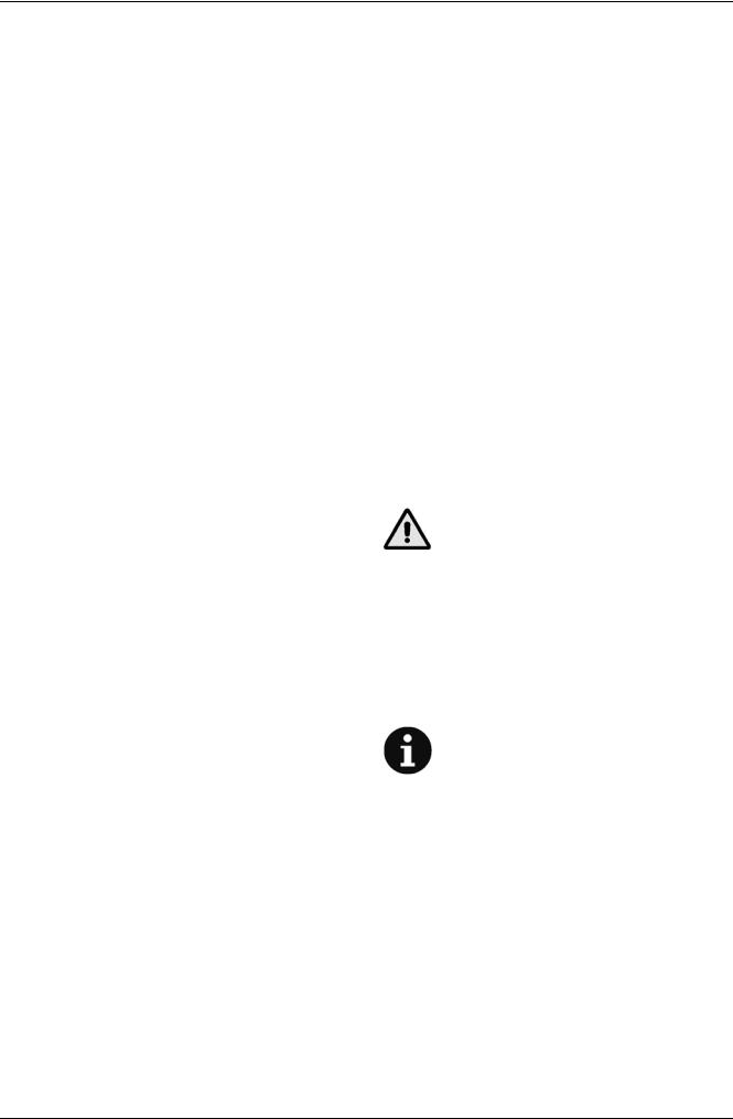
SQUEEGEE CLEANING
NOTE
The squeegee must be clean and its blades must be in good conditions in order to get a good drying.
CAUTION!
It is advisable to use protective gloves when cleaning the squeegee because there may be cutting debris.
1.Drive the machine on a level ground.
2.Check that the ignition key (10, Fig. B) is to “0” position.
3.Lower the squeegee (16, Fig. C) by means of the lever (25).
4.Disconnect the vacuum hose (24, Fig. C) from the squeegee.
5.Loosen the handwheels (17, Fig. C) and remove the squeegee (16).
6.Wash and clean the squeegee; in particular, clean the compartments (1, Fig. D) and the hole (2) from dirt and debris. Check the front blade (3) and the rear blade (4) for integrity, cuts and tears; otherwise replace them (see the procedure in the next paragraph).
7.Reassemble in the reverse order of disassembly.
12 |
Razor™ Plus 24D-26D-28D / Razor™ Plus 24C-28C — 909 5428 000(2)2005-01 |
|
|
|
INSTRUCTIONS FOR USE |
|
|
|
|
|
|
|
|||
|
|
|
|
|||
SQUEEGEE BLADE CHECK (AND |
TANK, VACUUM GRID WITH FLOAT AND |
|||||
REPLACEMENT) |
RECOVERY WATER RECIRCULATION |
|||||
1. Clean the squeegee (as described in the previous |
FILTER CLEANING (OPTIONAL) |
|||||
|
paragraph). |
1. |
Bring the machine to the appointed disposal area. |
|||
2. |
Check that the edges (5 and 12, Fig. D) of the front and |
|||||
2. |
Check that the ignition key (10, Fig. B) is to “0” position. |
|||||
|
rear blades lay down on the same level, along all their |
|||||
|
3. |
Lift the cover (1, Fig. G). |
||||
|
length; otherwise adjust their height as described below: |
|||||
|
4. |
Clean and wash with clean water the cover (1, Fig. G), |
||||
|
– disengage the retainer (6) and loosen the wing nuts |
|||||
|
|
the tanks (4 and 5) and the vacuum grid (7). |
||||
|
(7) to adjust the rear blade (4); then tighten the wing |
|
||||
|
|
Remove the plug (16, Fig. G) and clean the vacuum duct |
||||
|
nuts and engage the retainer; |
|
||||
|
|
with a bolt of water. Install the plug (16). |
||||
|
– loosen the wing nuts (8) to adjust the front blade (3); |
|
||||
|
|
Drain the water from the tanks with the hoses (26 and |
||||
|
then tighten the nuts. |
|
||||
|
|
27, Fig. C). |
||||
3. |
Check that the front blade (3) and rear blade (4) are |
|
||||
5. |
If necessary, release the retainers (13, Fig. G) and open |
|||||
|
integral and free from cuts and tears; otherwise replace |
|||||
|
|
the vacuum grid (7); recover the float (14), clean all the |
||||
|
them as described below. Check that the front corner (9) |
|
||||
|
|
components and then reinstall them. |
||||
|
of the rear blade is not worn; otherwise, overturn the |
|
||||
|
6. |
Check the integrity of the gasket (2, Fig. G) on the tank |
||||
|
blade to replace the worn corner with an integral one. If |
|||||
|
|
cover. |
||||
|
the other corners are worn too, replace the blade as |
|
||||
|
|
|
|
|
||
|
described below: |
|
NOTE: |
|||
|
– rear blade: disengage the retainer (6), unscrew the |
|
||||
|
|
The gasket (2, Fig. G) creates vacuum in the |
||||
|
wing nuts (7) and remove the retaining strip (10), |
|
||||
|
|
tank, which is necessary for vacuuming the |
||||
|
then replace (or overturn) the rear blade (4); install |
|
||||
|
|
recovery water. |
||||
|
the blade in the reverse order of removal; |
|
||||
|
|
If necessary replace the gasket (2) after removing it |
||||
|
– front blade: unscrew the wing nuts (8) and remove |
|
||||
|
the retaining strip (11), then replace the front blade |
|
from its seat (10). When assembling the new gasket, |
|||
|
(3); install the blade in the reverse order of removal. |
|
install its junction (11) in the central rear area as |
|||
|
After the blade replacement (or overturning), adjust |
|
shown in the figure. |
|||
|
the height as described at the previous step. |
7. |
Check that the seating surface (12, Fig. G) of the gasket |
|||
4. Install the squeegee (16, Fig. C) and screw down the |
|
(2) is integral and adequate for the gasket. |
||||
|
handwheels (17). |
8. |
Check that the compensation hole (3, Fig. G) is not |
|||
5. Connect the vacuum hose (24, Fig. C) to the squeegee |
|
obstructed, otherwise clean it. |
||||
|
(16). |
|
NOTE |
|||
6. If necessary, adjust the squeegee balance adjusting |
|
|||||
|
handwheel (18, Fig. C). |
|
The hole (3, Fig. G) allows compensating the |
|||
BRUSH/CYLINDRICAL BRUSH CLEANING |
|
air in the cover and contributes to create |
||||
|
vacuum in the tank. |
|||||
|
CAUTION! |
9. |
If equipped, remove the recirculation system filter (8, |
|||
|
It is advisable to use protective gloves when |
|
Fig. G) by turning it counter-clockwise. Clean and rinse |
|||
|
cleaning the brushes/cylindrical brushes |
|
the filter with clean water, than reinstall it. |
|||
|
because there can be cutting debris. |
|
CAUTION! |
|||
1. Remove the brushes/cylindrical brushes, as described in |
|
|||||
|
When removing/installing the filter (8, Fig. G), |
|||||
|
the Use chapter. |
|
take care not to damage the float (9). |
|||
2.Clean and wash the brushes/cylindrical brushes with
water and solution. |
10. Close the cover (1, Fig. G). |
3.Check that the brush/cylindrical brush bristles are integral and not excessively worn; otherwise replace the brushes/cylindrical brushes.
4.On the cylindrical brush-holder deck, remove the debris container (26, Fig. J) by pulling it on one side by means of the handle (27).
Empty and wash the debris container (26), and then install it by engaging it on the retainers.
Razor™ Plus 24D-26D-28D / Razor™ Plus 24C-28C — 909 5428 000(2)2005-01 |
13 |
 INSTRUCTIONS FOR USE
SOLUTION FILTER CLEANING
1.Drive the machine on a level ground.
2.Check that the ignition key (10, Fig. B) is to “0” position.
3.Operating on the right lower side of the machine, close the solution tap (5, Fig. F). The tap (5) is closed when it is on the position (6) as to the hoses; it is open when it is on the position (7).
4.Operating on the left lower side of the machine (at the “FILTER” mark), remove the transparent cover (1, Fig. F) and the wire gauze (2); clean and reinstall them on the support (3).
NOTE
The wire gauze (2) must be correctly positioned on the support (3) housing (4).
5.Reopen the tap (5, Fig. F).
CHARGING THE BATTERIES
NOTE:
Charge the batteries when the yellow and the red warning lights (9b or 9c, Fig. B) turn on, or at the end of each cleaning.
CAUTION!
Keeping the batteries charged make their life last longer.
CAUTION!
When the batteries are discharged, charge them as soon as possible, as that condition makes their life shorter.
Check for battery charge at least once a week.
CAUTION!
Use a battery charger suitable for the type of batteries installed.
–clean (if necessary) the upper surface of the batteries.
5.Charge the batteries according to one of the following procedures, depending on the presence of the electronic battery charger (1, Fig. E).
Battery charging with battery charger installed on the machine
1.For lead batteries only:
–check the electrolyte level inside the batteries; if necessary top up through the caps (9, Fig. J);
–When the correct level is reached, close the caps (9) and clean (if necessary) the upper surface of the batteries.
2.Connect the battery charger cable (31, Fig. C) to the electrical mains (voltage and frequency must be compatible with the battery charger values on the machine serial number plate).
When the battery charger is connected to the mains, all machine functions are automatically cut off.
If the red warning light (2a, Fig. E) on the battery charger control panel stays on, the battery charger is charging the batteries.
3.When the green warning light (2c, Fig. E) turns on, the battery charging is completed.
4.Once the battery charging is completed, disconnect the battery charger cable (31, Fig. C) from the electrical mains and wind it round its support (32).
5.Carefully lower the tank assembly (4, Fig. J) with the handlebar (2, Fig. C).
6.Turn the handwheel (3, Fig. J) clockwise until the tank assembly is locked.
7.When the tank (4, Fig. G) has been filled, the machine is ready to be used (see the related paragraph for the procedure).
NOTE
For further information about the battery charger (1, Fig. E) operation, see the related manual.
WARNING!
Lead/acid battery charging produces highly explosive hydrogen gas. Charge the batteries in well-ventilated areas and away from naked flames.
Do not smoke while charging the batteries. While charging the battery, always keep the tank assembly open.
WARNING!
Be extremely careful when charging the batteries as there may be battery fluid leakages. The battery fluid is corrosive. If it comes in contact with the skin or eyes, rinse thoroughly with water and consult a physician.
1.Drive the machine on a level ground.
2.Turn the handwheel (3, Fig. J) counter-clockwise until the tank assembly is released.
3.Carefully lift the tank assembly (4, Fig. J) with the handlebar (2, Fig. C).
4.For lead batteries only:
–check the electrolyte level inside the batteries (8, Fig. J); if necessary top up through the caps (9);
–leave all the caps (9) open for next charging;
FUSE CHECK/REPLACEMENT
1.Disconnect the battery connector (30, Fig. C).
2.Remove the handle (15, Fig. E) from the squeegee lifting/lowering lever.
3.Unscrew the nuts (16, Fig. E), carefully remove the cover (9), and move the panel (11) as necessary.
4.Check/replace the following fuses:
–Function electronic board fuse (100A) (7, Fig. E);
–Drive electronic board fuse (30A) (8, Fig. E).
5.Carry out steps from 1 to 3 in the reverse order.
14 |
Razor™ Plus 24D-26D-28D / Razor™ Plus 24C-28C — 909 5428 000(2)2005-01 |
|
|
INSTRUCTIONS FOR USE |
|
|
||
|
|
|
||||
|
|
|
||||
DISASSEMBLY/ASSEMBLY OF THE |
SAFETY FUNCTIONS |
|||||
BRUSH-HOLDER/PAD-HOLDER DECK OR |
Safety connector |
|
|
|
||
CYLINDRICAL BRUSH-HOLDER DECK |
|
|
|
|||
The red connector (30, Fig. C) can be used in case of |
||||||
|
NOTE |
emergency to stop all the machine functions. If necessary, |
||||
|
remove the connector with the red handle. |
|||||
|
On the machines from Serial Number 1776829, |
|||||
|
|
|
|
|
||
|
it is possible to install either a |
TROUBLESHOOTING |
||||
|
brush-holder/pad-holder deck (12, Fig. C) or a |
|||||
|
cylindrical brush-holder deck (15), according |
|
|
|
|
|
|
TROUBLE |
POSSIBLE CAUSE |
||||
|
to the following instructions. |
|||||
|
|
|
|
|
||
|
The motors do not work; no |
Disconnected battery connector (30, |
||||
|
|
|||||
Disassembly |
Fig. C) |
|||||
warning light turns on |
||||||
1. If there is recovery water in the tank (5, Fig. G) drain it |
Completely discharged batteries |
|||||
|
||||||
|
through the hose (26, Fig. C). |
|
|
|||
|
|
Drive cut-off switch (36, Fig. C) in “0” |
||||
2. If there is solution in the tank (4, Fig. G) drain it through |
|
position |
||||
|
the hose (27, Fig. C). |
The machine does not move |
|
|
|
|
|
The machine has been turned on |
|||||
3. |
Drive the machine on a level ground. |
|||||
|
with the key (10, Fig. B) and by |
|||||
4. Turn the ignition key (10, Fig. B) to “0” position. |
|
|||||
|
pressing the paddle (4, Fig. C) |
|||||
5. |
Disconnect the battery connector (30, Fig. C). |
|
|
|
|
|
|
The machine has been turned off |
|||||
6. |
Unscrew the handwheel (3, Fig. J). |
|
||||
At the machine start-up, the |
without lifting the brush-holder deck: |
|||||
7. |
By means of the handlebar (2, Fig. C) lift the tank |
|||||
warning light (2, Fig. B) |
wait for the deck to reach the lifted |
|||||
|
assembly (4, Fig J) completely to operate on the deck |
|||||
|
flashes and the brushes do |
position before activating the again |
||||
|
(12 or 22, Fig. J). |
not work |
the brushes by means of the switch |
|||
8. Disconnect the solution hose (21, Fig. J) from the deck. |
|
(2, Fig. B) |
||||
9. |
Disconnect the motor connector (11, Fig. J). |
|
|
|
|
|
|
Brush motor overload: use less |
|||||
10. Remove the two cotter pins (19, Fig. J). |
|
|||||
|
aggressive brushes and/or avoid |
|||||
11. Unscrew the handwheel (20, Fig. J) and remove the |
The warning lights (9a, 9b, |
working with extra pressure activated |
||||
|
brush-holder/pad-holder deck (12) or the cylindrical |
9c, Fig. B) flashes |
|
|
|
|
|
The cylindrical brush-holder deck is |
|||||
|
brush-holder deck (22). |
|||||
|
simultaneously |
installed on the machine, but the gas |
||||
12. According to the type of deck, remove the spoiler (14, |
|
spring (1, Fig H) has not been taken |
||||
|
Fig. J) or the spoiler (29) by disengaging the retainers. |
|
in the position (1, Fig. I) |
|||
Assembly |
|
|
|
|
||
The brushes do not work, |
|
|
|
|||
13. Assemble the components in the reverse order of |
the red warning light (9c, Fig. |
Discharged batteries |
||||
|
disassembly, and pay particular attention to the |
B) is on |
|
|
|
|
|
following: |
|
Full recovery tank (5, Fig. G) |
|||
|
– when the brush-holder/pad-holder deck (12, Fig. J) is |
|
|
|
|
|
|
|
Obstructed vacuum grid (7, Fig. G) |
||||
|
installed on the machine, the gas spring must be |
|
||||
|
|
or stuck closed float |
||||
|
connected [active position (1, Fig. H)], as show in the |
|
|
|
|
|
|
|
Hose (24, Fig. C) disconnected from |
||||
|
figure; |
|
||||
|
Insufficient dirty water |
the squeegee |
||||
|
– when the cylindrical brush-holder deck (22, Fig. J) is |
|||||
|
|
|
|
|||
|
Dirty squeegee (16, Fig. C), or worn |
|||||
|
installed on the machine, the gas spring must be |
vacuuming |
||||
|
disconnected [idle position (1, Fig. I)] by disengaging |
|
or damaged squeegee blades |
|||
|
the end (2, Fig. H) from the ball joint (3) and locking |
|
Incorrectly closed tank cover, or |
|||
|
it on the stopper (2, Fig. I). |
|
damaged gasket (2, Fig. G) or |
|||
|
|
|
obstructed compensation hole (3, |
|||
|
CAUTION! |
|
Fig. G) |
|||
|
|
|
|
|
||
|
When the cylindrical brush-holder deck (22, |
The vacuum motor stops |
Full recovery tank (5, Fig. G) |
|||
|
Fig. J) is installed on the machine, if the gas |
Insufficient solution flow to |
Dirty solution filter (28, Fig. C) |
|||
|
spring is in the active position (1, Fig. H), the |
|
|
|
||
|
Dirty tank (4, Fig. C) (obstructed |
|||||
|
system detects a deck pressure on the ground |
the brushes |
||||
|
output hole) |
|||||
|
|
|||||
|
overload, and the warning lights (9a, 9b, 9c, |
|
|
|
|
|
|
|
Debris under the squeegee blades |
||||
|
Fig. B) turn on. |
|
||||
|
|
|
|
|
||
|
|
|
Worn, chipped or torn squeegee |
|||
|
|
Squeegee-related marks |
blades |
|||
|
|
|
|
|||
|
|
|
Not handwheel-balanced squeegee |
|||
|
|
|
(18, Fig. C) |
|||
|
|
|
|
|
|
|
If the machine has an optional battery charger installed, the machine cannot operate if the charger is not on board. In case of battery charger malfunction, contact an authorized Service Center.
For further information refer to the Service Manual, available at any Kent Service Center.
Razor™ Plus 24D-26D-28D / Razor™ Plus 24C-28C — 909 5428 000(2)2005-01 |
15 |

 INSTRUCTIONS FOR USE
SCRAPPING
Have the machine scrapped by a qualified scrapper. Before scrapping the machine, remove the following components:
a)Battery
b)Brush
c)Pad
d)Motors
e)Electronic boards
CAUTION!
The removed components must be disposed of properly according to the Law in force.
16 |
Razor™ Plus 24D-26D-28D / Razor™ Plus 24C-28C — 909 5428 000(2)2005-01 |

INSTRUCTIONS D'UTILISATION |
|
INTRODUCTION ................................................................................................................................... |
2 |
BUT ET CONTENU DU MANUEL .................................................................................................................... |
2 |
DESTINATAIRES ............................................................................................................................................. |
2 |
CONSERVATION DU MANUEL ....................................................................................................................... |
2 |
DONNEES D’IDENTIFICATION ....................................................................................................................... |
2 |
AUTRES MANUELS DE REFERENCE ............................................................................................................ |
2 |
PIECES DE RECHANGE ET ENTRETIEN ...................................................................................................... |
2 |
MODIFICATIONS ET AMELIORATIONS ......................................................................................................... |
2 |
SECURITE ............................................................................................................................................. |
2 |
SYMBOLES UTILISES ..................................................................................................................................... |
2 |
INSTRUCTIONS GENERALES ........................................................................................................................ |
2 |
DEBALLAGE ......................................................................................................................................... |
3 |
DESCRIPTION DE LA MACHINE ......................................................................................................... |
3 |
CAPACITES OPERATIONNELLES DE L'AUTOLAVEUSE ............................................................................. |
3 |
CONVENTIONS ................................................................................................................................................ |
3 |
DESCRIPTION DU TABLEAU DE BORD ........................................................................................................ |
4 |
DESCRIPTION DES VUES EXTERIEURES ARRIERE ................................................................................... |
4 |
DESCRIPTION DES VUES EXTERIEURES AVANT SOUS COUVERCLE ET DES RESERVOIRS .............. |
4 |
CARACTERISTIQUES TECHNIQUES ............................................................................................................. |
5 |
SCHEMAS ELECTRIQUES .............................................................................................................................. |
6 |
FUSIBLES ELECTRIQUES .............................................................................................................................. |
6 |
ACCESSOIRES/OPTIONS ............................................................................................................................... |
6 |
UTILISATION ........................................................................................................................................ |
6 |
CONTROLE/PREPARATION DES BATTERIES SUR UNE MACHINE NOUVELLE ....................................... |
6 |
INSTALLATION ET CONFIGURATIONS BATTERIES (WET OU GEL) .......................................................... |
7 |
AVANT LA MISE EN MARCHE DE LA MACHINE ........................................................................................... |
7 |
INSTALLATION/REMPLACEMENT DE LA TETE ............................................................................................ |
7 |
MISE EN MARCHE ET ARRET DE LA MACHINE ........................................................................................... |
9 |
FONCTIONNEMENT DE LA MACHINE ........................................................................................................... |
9 |
VIDANGE RESERVOIRS ............................................................................................................................... |
10 |
APRES L'UTILISATION DE LA MACHINE ..................................................................................................... |
11 |
DEPLACEMENT PAR POUSSEE/ REMORQUAGE DE LA MACHINE ......................................................... |
11 |
INACTIVITE PROLONGEE DE LA MACHINE ............................................................................................... |
11 |
PREMIERE PERIODE D'UTILISATION .......................................................................................................... |
11 |
ENTRETIEN ......................................................................................................................................... |
11 |
PLAN RECAPITULATIF D'ENTRETIEN PROGRAMME ................................................................................ |
12 |
NETTOYAGE DE L'EMBOUCHURE .............................................................................................................. |
12 |
CONTROLE (ET REMPLACEMENT) DES LAMELLES EN CAOUTCHOUC DE L'EMBOUCHURE ............. |
13 |
NETTOYAGE DES BROSSES/BROSSES CYLINDRIQUES ......................................................................... |
13 |
NETTOYAGE DES RESERVOIRS, DE LA GRILLE D'ASPIRATION AVEC FLOTTEUR ET DU FILTRE DE |
|
RECYCLAGE DE L'EAU DE RECUPERATION (OPTIONNEL) ..................................................................... |
13 |
NETTOYAGE DU FILTRE DE LA SOLUTION ............................................................................................... |
14 |
CHARGE DES BATTERIES ........................................................................................................................... |
14 |
CONTROLE/REMPLACEMENT FUSIBLES ................................................................................................... |
14 |
DEMONTAGE/REMONTAGE DE LA TETE PORTE-BROSSES/PLATEAUX SUPPORT DISQUE OU DE LA |
|
TETE PORTE-BROSSES CYLINDRIQUES ................................................................................................... |
15 |
FONCTIONS DE SECURITE ............................................................................................................... |
15 |
DEPISTAGE DES PANNES ................................................................................................................ |
15 |
MISE EN DECHARGE ......................................................................................................................... |
16 |
Razor™ Plus 24D-26D-28D / Razor™ Plus 24C-28C — 909 5428 000(2)2005-01 |
1 |
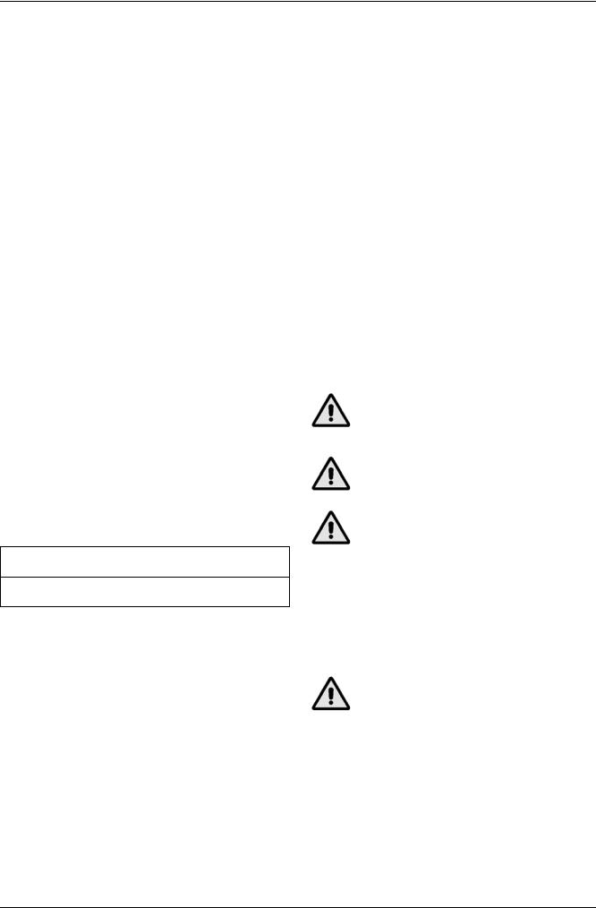
 INSTRUCTIONS D'UTILISATION
INTRODUCTION |
MODIFICATIONS ET AMELIORATIONS |
BUT ET CONTENU DU MANUEL
Ce manuel se propose de fournir à l'opérateur toutes les informations nécessaires afin qu’il puisse utiliser la machine correctement et la gérer dans la manière la plus autonome et sûre. Il comprend des informations relatives à l’aspect technique, le fonctionnement, l’arrêt de la machine, l’entretien, les pièces de rechange et la sécurité.
Avant d’effectuer toute opération sur la machine, les opérateurs et les techniciens chargés de l'entretien doivent lire attentivement ce manuel. En cas de doutes sur la correcte interprétation des instructions, contacter un Service après-vente qualifié Kent pour avoir plus de renseignements.
DESTINATAIRES
Ce manuel s’adresse à l’opérateur aussi bien qu’aux techniciens qualifiés pour effectuer l'entretien de la machine. Les opérateurs ne doivent pas exécuter les opérations réservées aux techniciens qualifiés. Kent ne répond pas des dommages dus à l'inobservance de cette interdiction.
CONSERVATION DU MANUEL
Le manuel d'emploi et d'entretien doit être gardé près de la machine, dans une enveloppe spéciale et, surtout, loin de liquides et de tout ce qui pourrait en compromettre l’état de lisibilité.
DONNEES D’IDENTIFICATION
Le numéro de série et le modèle de la machine sont marqués sur la plaque appliquée sur le réservoir et lisible de l'extérieur. (1, Fig. C).
L'année de fabrication de la machine est indiquée après le code de la date sur le numéro de série de la machine. (A05 signifie janvier 2005).
Ces informations sont nécessaires lors de la commande des pièces de rechange de la machine. Utiliser l'espace ci-dessous pour noter les données d'identification de machine pour une référence future.
Modèle MACHINE ...........................................................
Numéro de série de la MACHINE ...................................
Kent vise à un constant perfectionnement de ses produits et se réserve le droit d’effectuer des modifications et des améliorations, si nécessaires, sans l’obligation de sa part de modifier les machines déjà vendues.
Il est entendu que toute modification et/ou addition d’accessoires doit toujours être approuvée et réalisée par Kent.
SECURITE
Kent utilise la symbologie suivante pour signaler les conditions de danger potentielles. Lire attentivement ces informations et prendre les précautions nécessaires pour protéger les personnes et les choses.
Pour éviter tout accident la collaboration de l'opérateur de la machine est essentielle. Aucun programme de prévention des accidents du travail ne peut être efficace sans la totale collaboration de la personne directement responsable du fonctionnement de la machine. La plupart des accidents qui peuvent survenir dans une entreprise, pendant le travail ou les déplacements, sont dus à l’inobservance des plus simples règles de prudence. Un opérateur attentif et prudent est la meilleure garantie contre les accidents du travail et se révèle indispensable pour compléter n’importe quel programme de prévention.
SYMBOLES UTILISES
DANGER !
Indique une situation dangereuse exposant l'opérateur au risque de blessures graves, voire mortelles.
ATTENTION !
Indique une situation exposant les personnes au risque de blessures.
AVERTISSEMENT !
Indique un avertissement sur des fonctions clé ou utiles. Prêter la plus grande attention aux segments de texte marqués par ce symbole.
REMARQUE
Indique la nécessité de consulter le manuel avant toute opération.
AUTRES MANUELS DE REFERENCE
Manuel d’utilisation du chargeur de batterie électronique, qui constitue une partie intégrante de ce manuel.
En outre les suivants manuels sont disponibles :
–Manuel d’entretien consultable auprès des Services après-vente Kent.
–Catalogue de pièces de rechange, livré avec la machine.
PIECES DE RECHANGE ET ENTRETIEN
Pour toute nécessité concernant l’utilisation, l’entretien extraordinaire et les réparations, si nécessaires, il faut s’adresser au personnel qualifié ou directement aux Services après-vente Kent. Il ne faut utiliser que de pièces de rechange et accessoires originaux.
Pour l’assistance ou la commande de pièces de rechange et accessoires, contacter Kent en spécifiant toujours le modèle et le numéro de série.
INSTRUCTIONS GENERALES
Description de quelques potentiels dangers de dommages matériels ou blessures.
DANGER !
–Avant d'effectuer toute opération d'entretien/réparation, débrancher la batterie.
–Cette machine doit être utilisée uniquement par un personnel adéquatement formé et autorisé. L’utilisation de la machine est interdite aux enfants et aux personnes handicapées.
–Tenir les étincelles, les flammes et les matériaux incandescents à distance des batteries. Les batteries produisent des gaz potentiellement explosifs pendant l'utilisation ordinaire.
–Ne pas porter de bijoux lorsqu'on travaille près de composants électriques.
2 |
Razor™ Plus 24D-26D-28D / Razor™ Plus 24C-28C — 909 5428 000(2)2005-01 |
INSTRUCTIONS D'UTILISATION 
–Ne pas travailler sous la machine soulevée, sans des supports fixes de sécurité convenables.
–Ne pas opérer avec cette machine en présence de poudres, liquides ou vapeurs nuisibles, dangereux, inflammables et/ou explosifs.
–En chargeant les batteries un gaz hydrogène très explosif est produit. Garder les réservoirs ouverts pendant le cycle de chargement des batteries et effectuer l’opération exclusivement dans un endroit bien aéré et loin de flammes libres.
ATTENTION !
–Avant d'effectuer toute activité d'entretien/réparation, lire avec attention toutes les instructions.
–Avant d'utiliser le chargeur de batterie, s'assurer que la fréquence et la tension indiquées sur la plaque avec numéro de série coïncident avec la tension du réseau.
–Prendre les précautions convenables afin que les cheveux, les bijoux, les parties non adhérentes des vêtements ne soient pas capturés par les parties en mouvement.
–Ne pas fumer pendant la charge des batteries.
–Ne pas laisser la machine sans surveillance et s'assurer que la machine ne peut pas bouger de façon autonome.
–Ne pas laver la machine avec des jets d’eau directs ou sous pression ou avec des substances corrosives.
–Ne pas utiliser la machine dans des milieux particulièrement poussiéreux.
–Pendant l'utilisation de la machine, sauvegarder l'intégrité des autres personnes, en particulier des enfants.
–Ne pas poser de conteneurs de liquides sur la machine.
–La température de stockage doit être comprise entre 0°C et +40°C (+32°F et +104°F).
–La température de travail de la machine doit être comprise entre 0°C et 40°C (+32°F et +104°F).
–L’humidité doit être comprise entre 30% et 95%.
–Protéger toujours la machine du soleil, pluie et d’autres intempéries, et en état de fonctionnement et en état d’arrêt.
–Ne pas utiliser la machine comme moyen de transport.
–Ne pas utiliser la machine sur des rampes ou sur des inclinaisons supérieures à 2%.
–Ne pas faire travailler les brosses lorsque la machine est arrêtée pour ne pas endommager le sol.
–En cas d’incendie, il est préférable d'utiliser un extincteur à poudre, plutôt qu'un extincteur à eau.
–Ne pas heurter contre des étagères ou des échafaudages, en particulier en présence de danger de chute d’objets.
–Ne pas altérer pour aucune raison les protections prévues pour la machine, respecter scrupuleusement les instructions prévues pour l’entretien ordinaire.
–Ne pas enlever ou altérer les plaques apposées sur la machine.
–Vérifier que les éventuelles anomalies de fonctionnement ne dépendent pas du manque d'entretien. En cas contraire demander l'intervention de personnel autorisé ou d'un Service après-vente autorisé.
–En cas de remplacement de pièces, demander les pièces de rechange D’ORIGINE à un concessionnaire ou revendeur autorisé.
–Afin de garantir la sécurité et le bon fonctionnement de la machine, faire effectuer l'entretien programmé prévu au chapitre spécifique de ce manuel par du personnel autorisé ou par un Service après-vente autorisé.
–La machine ne doit pas être abandonnée lors de la mise en décharge, à cause de la présence de matériaux toxiques (batteries, etc.), sujets à des lois qui prévoient l’élimination auprès de centres spéciaux (voir le chapitre Mise en décharge).
–En conditions d’emploi conformes aux indications d’utilisation correcte, les vibrations ne provoquent pas
de situations de danger. Le niveau de vibrations de la machine est inférieur à 2,5 m/s2.
–Ne pas laisser entrer d'objets dans les ouvertures. Ne pas utiliser la machine si les ouvertures sont bouchées ; garder les ouvertures de la machine libres de poussière, filasse, poils et tout autre corps étranger à même de réduire le flux d'air.
–Cette machine n'est pas approuvée pour l'utilisation sur les rues publiques.
–Faire attention pendant les déplacements de la machine en conditions de températures inférieures au point de congélation. L'eau présente dans le réservoir de récupération ou dans les tuyaux pourrait se congeler et endommager sérieusement la machine.
–Utiliser les brosses et les plateaux support disque équipés et ceux spécifiés dans les manuels d'emploi et d'entretien. L'utilisation d'autres brosses ou plateaux support disque peut compromettre la sécurité.
DEBALLAGE
Lors de la livraison de la machine, contrôler attentivement que l’emballage et la machine n’ont pas été endommagés pendant le transport. Si les dommages sont évidents, garder l'emballage de façon qu'il puisse être examiné par le transporteur qui l'a livré. Le contacter immédiatement pour remplir une demande de dommages-intérêts.
Contrôler que les composants suivants se trouvent toujours avec la machine :
1.Documentation technique :
–Mode d'emploi et d'entretien de l'autolaveuse
–Manuel d'utilisation du chargeur de batterie électronique
–Catalogue de pièces de rechange de l'autolaveuse
2.N° 2 fusibles lamellaires
3.N° 5 cales pour logement de batterie de 6V
DESCRIPTION DE LA MACHINE
CAPACITES OPERATIONNELLES DE L'AUTOLAVEUSE
L'autolaveuse est utilisée pour le nettoyage (lavage et séchage) de sols lisses et solides, en milieux civils et industriels, en conditions de complète sécurité, par un opérateur qualifié.
L'autolaveuse ne doit pas être utilisée pour le lavage de tapis ou moquettes.
CONVENTIONS
Toutes les références à en avant, en arrière, avant, arrière, droite ou gauche indiquées dans ce manuel doivent être considérées comme référées à l'opérateur en position de conduite, les mains sur le guidon (2, Fig. C).
Razor™ Plus 24D-26D-28D / Razor™ Plus 24C-28C — 909 5428 000(2)2005-01 |
3 |
 Loading...