


Kenmore 79032439902, 79032439903, 79032434902, 79032434903, 79032433902 Installation Guide
...
iNSTALLATiON AND SERVICE MUST BE PERFORMED BY A QUALiFiED iNSTALLER.
iMPORTANT: SAVE FOR LOCAL ELECTRICAL iNSPECTOR'S USE.
READ AND SAVE THESE iNSTRUCTiONS FOR FUTURE REFERENCE.
If the information in this manual is not followed exactly, a fire or explosion may result
causing property damage, personal injury or death.
FOR YOUR SAFETY:
Do not store or use gasoline or other flammable vapors and liquids in the
vicinity of this or any other appliance.
B
WHAT TO DO IF YOU SMELL GAS:
®
Do not try to light any appliance.
®
Do not touch any electrical switch; do not use any phone in your building.
®
Immediately call your gas supplier from a neighbor's phone.
Follow the gas supplier's instructions.
®
if you cannot reach your gas supplier, call the fire department.
Installation and service must be performed by a qualified installer, service agency or the gas
supplier.
i
30" GasCooktop
36" GasCooktop
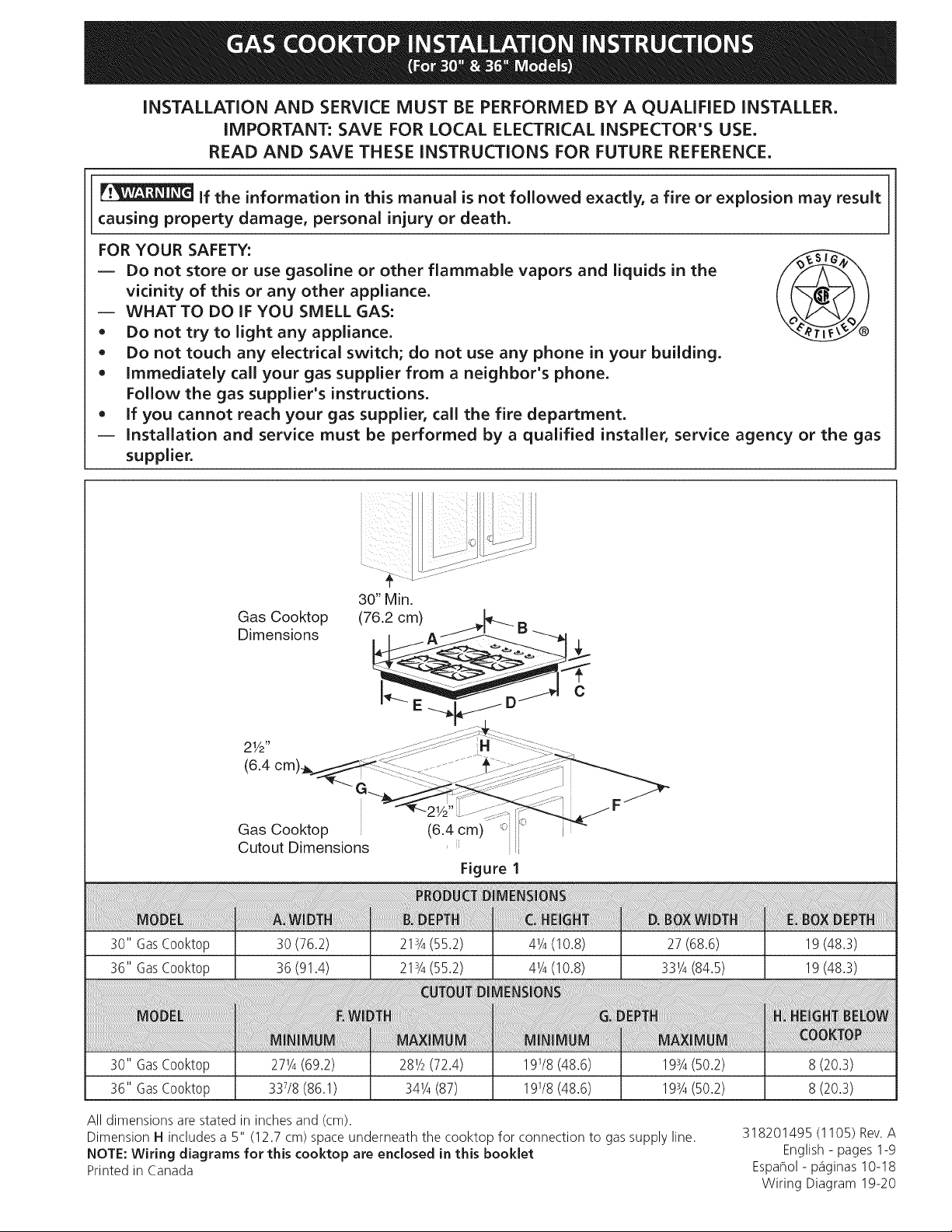
30" Min.
Gas Cooktop (76.2 cm) _ B
Dimensions . _ A/:J- ----_
21/2 - -::::::_::(_-.... H ...... _ _--c::- ....
Gas Cooktop (6.4 cm) _c ;_
Cutout Dimensions ' ii
Figure I
30 (76.2)
36 (91.4)
21s/4(55.2)
21s/4(55.2)
41/4(10.8)
41/4(10.8)
c
27 (68.6)
331/4(84.5)
19(48.3)
19(48.3)
30" GasCooktop 271/4(69.2) 281/2(72.4) 191/8(48.6) 198/4(50.2) 8 (20.3)
36" GasCooktop 337/8(86.1) 341/4(87) 191/8(48.6) 19Y4(50.2) 8 (20.3)
All dimensions are stated in inches and (cm).
Dimension H includes a 5" (12.7 cm) space underneath the cooktop for connection to gas supply line.
NOTE: Wiring diagrams for this cooktop are enclosed in this booklet
Printed in Canada
318201495 (1105) Rev.A
English - pages 1-9
Espaflol - p_iginas 10-18
Wiring Diagram 19-20
important Notes to the Installer
1. Read all instructions contained in these installation
instructions before installing the cooktop.
2. Remove all packing material before connecting the
electrical supply to the cooktop.
3. Observe all governing codes and ordinances.
4. Be sure to leave these instructions with the consumer.
5. Note: For operation at 2000 ft. elevations above see
level, appliance rating shall be reduced by 4 percent
for each additional 1000 ft.
important Note to the Consumer
Keep these instructions with your Use and Care Guide for
future reference.
IMPORTANT SAFETY
INSTRUCTION
Installation of this cooktop must conform with local
codes or, in the absence of local codes, with the National
Fuel Gas Code ANSI Z223.1/NFPA 54 in the United
States, or in Canada, with the Canadian Fuel Gas Code,
CAN/CGA B149 and CAN/CGA B149.2.
• When installed in a manufactured (mobile) home
installation must conform with the Manufactured
Home Construction and Safety Standard, title 24 CFR,
part 3280 [Formerly the Federal Standard for Mobile
Home Construction and Safety, title 24, HUD (part
280)] or, when such standard is not applicable, the
Standard for Manufactured Home Installation, ANSI/
NCSBCSA225.1 or with local codes where applicable.
This cooktop has been design certified by CSA
International. As with any appliance using gas and
generating heat, there are certain safety precautions you
should follow. You will find them in the Use and Care
Guide., read it carefully.
Be sure your cooktop is installed and grounded
properly by a qualified installer or service
technician.
This cooktop must be electrically grounded in
accordance with local codes or, in their absence,
with the National Electrical Code ANSI/NFPA
No. 70--latest edition in the United States, or in
Canada, with the Canadian Electrical Code, CSA
C22.1 Part 1.
The burners can be lit manually during an
electrical power outage. To light a burner, hold a
lit match to the burner head, then slowly turn the
Surface Control knob to LITE. Use caution when
lighting burners manually.
Do not store items of interest to children in
cabinets above the cooktop. Children could be
seriously burned climbing on the cooktop to reach
items.
To eliminate the need to reach over the surface
burners, cabinet storage space above the burners
should be avoided.
Adjust surface burner flame size so it does not
extend beyond the edge of the cooking utensil.
Excessiveflame is hazardous.
Never use your cooktop for warming or heating
the room. Prolonged use of the cooktop without
adequate ventilation can be hazardous.
Do not store or use gasoline or other flammable
vapors and liquids near this or any other
appliance. Explosions or fires could result.
The electrical power to the cooktop
must be shut off while gas line connections are
being made. Failure to do so could result in serious
injury or death.
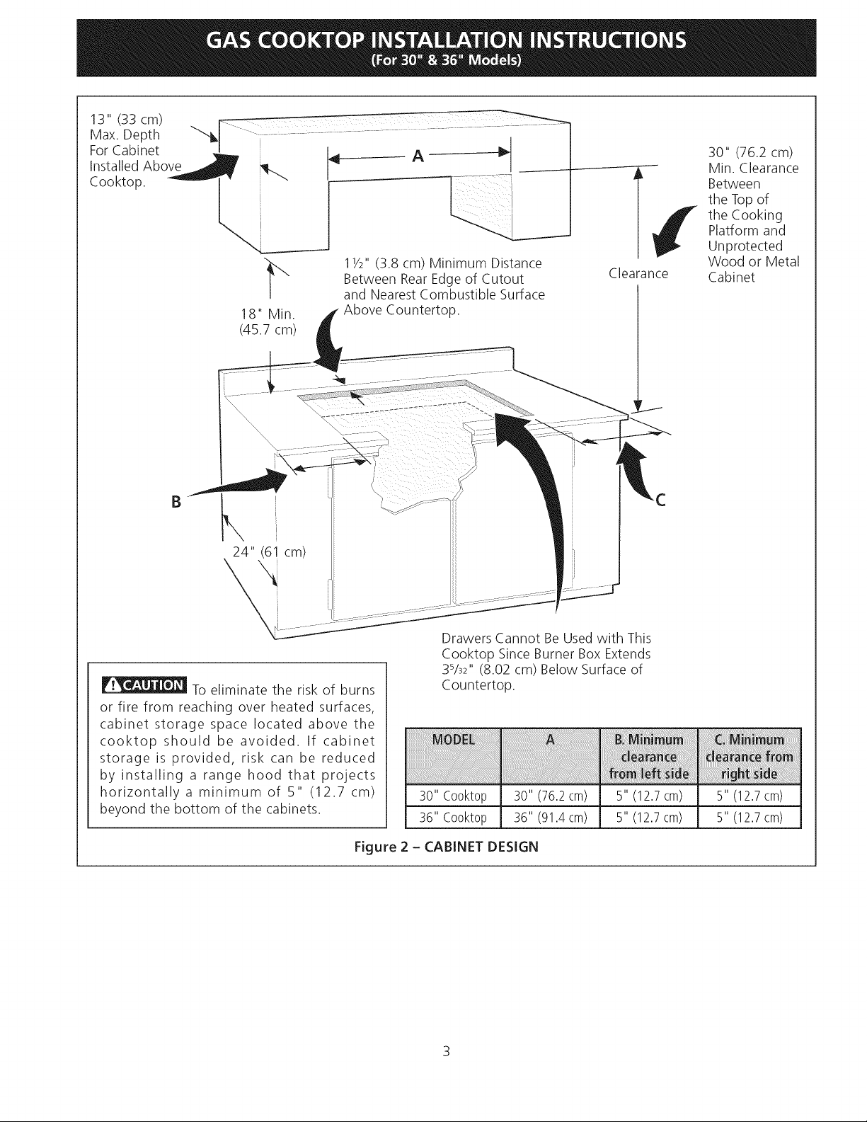
13"(33cm)
Max.Depth
ForCabinet
InstalledAbove
Cooktop.
18"Min.
(45.7cm)
11/2"(3.8cm)MinimumDistance
BetweenRearEdgeofCutout
andNearestCombustibleSurface
AboveCountertop.
30"(76.2cm)
Between
the Top of
the Cooking
_¢ in. Clearance
Clearance Cabinet
Platform and
Unprotected
Wood or Metal
B
To eliminate the risk of burns
or fire from reaching over heated surfaces,
cabinet storage space located above the
cooktop should be avoided. If cabinet
storage is provided, risk can be reduced
by installing a range hood that projects
horizontally a minimum of 5" (12.7 cm)
beyond the bottom of the cabinets.
I
24" (6! cm)
Figure 2 - CABINET DESIGN
Drawers Cannot Be Used with This
Cooktop Since Burner Box Extends
3%2" (8.02 cm) Below Surface of
Countertop.
30" C00kt0p 30" (76.2cm) 5" (12.7cm) 5" (12.7cm)
36" C00kt0p 36" (91.4cm) 5" (12.7cm) 5" (12.7cm)
3
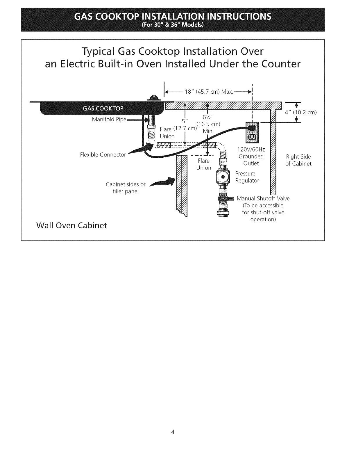
Typical Gas Cooktop Installation Over
an Electric Built-in Oven Installed Under the Counter
I I18" (45.7 cm) Max.-----_ I
I
4" (10.2 cm)
Manifold Pi
61/2"
5" .(16.5 cm)
Flare (12.7 cm) Min.
Union
÷
Flexible Connector
Wall Oven Cabinet
Cabinet sides or
filler panel
Flare
Union
120V/6OHz
Grounded
Outlet
Pressure
Regulator
Manual Shutoff Valve
(Tobe accessible
for shut-off valve
operation)
Right Side
of Cabinet
Typical
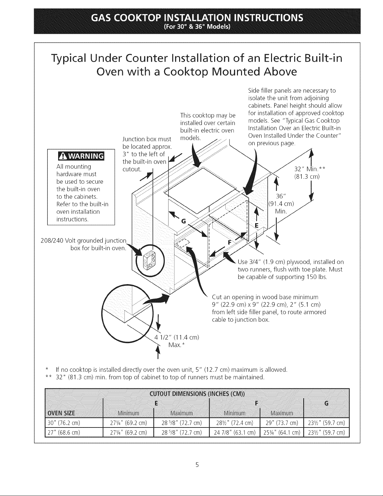
All mounting
hardware must
be used to secure
the built-in oven
to the cabinets.
Refer to the built-in
oven installation
instructions.
Under Counter Installation of an Electric Built-in
Oven with a Cooktop Mounted Above
Side filler panels are necessary to
isolate the unit from adjoining
cabinets. Panelheight should allow
for installation of approved cooktop
models. See "Typical GasCooktop
Installation Over an Electric Built-in
Oven Installed Under the Counter"
on previous page.
36"
(91.4 cm)
Junction box must
be located approx.
3" to the left of
the built-in oven
cutout.
This cooktop may be
installed over certain
built-in electric oven
models.
32" Min.**
(81.3 cm)
208/240 Volt grounded junction
box for built-in oven.
Use 3/4" (1.9 cm) plywood, installed on
two runners, flush with toe plate. Must
be capable of supporting 150 Ibs.
Cut an opening in wood base minimum
9" (22.9 cm) x 9" (22.9 cm), 2" (5.1 cm)
from left side filler panel, to route armored
cable to junction box.
4 1/2" (11.4cm)
Max.*
* If no cooktop is installed directly over the oven unit, 5" (12.7 cm) maximum isallowed.
** 32" (81.3 cm) min. from top of cabinet to top of runners must be maintained.
30" (76.2cm) 271/4"(69.2cm) 28 s/8"(72.7 cm) 281/2"(72.4cm) 29" (73.7cm) 231/2"(59.7cm)
27" (68.6cm) 271/4'' (69.2cm) 28 s/8" (72.7cm) 24 7/8" (63.1cm) 251/4'' (64.1 cm) 231/2'' (59.7cm)
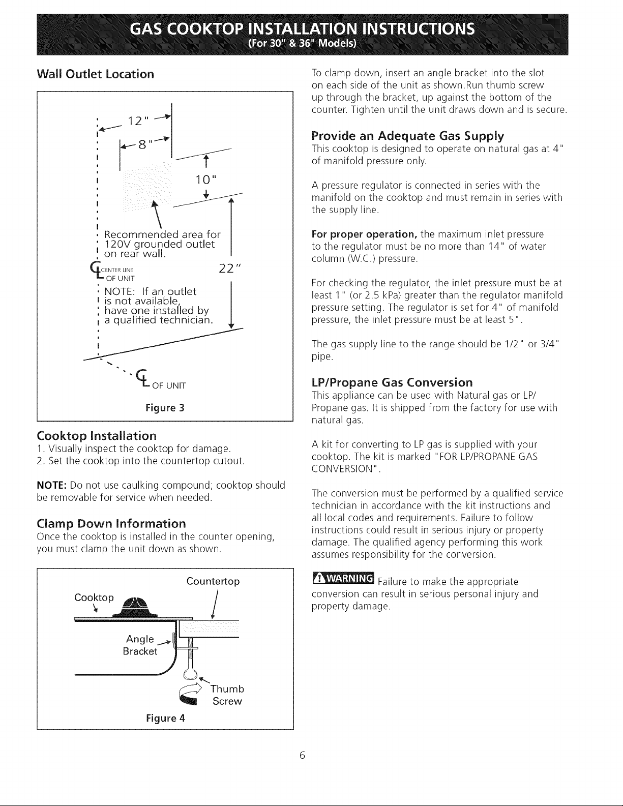
Wall Outlet Location
, 12,, --_
I 1 0 "
I
, Recommended area for
' 12OV grounded outlet
u on rear wall.
m
CL_olFUL_ET 22 "
: NOTE: If an outlet
J is not available, I
: have one installed by I
t a qualified technician.
To clamp down, insert an angle bracket into the slot
on each side of the unit as shown.Run thumb screw
up through the bracket, up against the bottom of the
counter. Tighten until the unit draws down and is secure.
Provide an Adequate Gas Supply
This cooktop is designed to operate on natural gas at 4"
of manifold pressure only.
A pressure regulator is connected in series with the
manifold on the cooktop and must remain in series with
the supply line.
For proper operation, the maximum inlet pressure
to the regulator must be no more than 14" of water
column (W.C.) pressure.
For checking the regulator, the inlet pressure must be at
least 1" (or 2.5 kPa) greater than the regulator manifold
pressure setting. The regulator is set for 4" of manifold
pressure, the inlet pressure must be at least 5".
The gas supply line to the range should be 1/2" or 3/4"
pipe.
OF UNIT
Figure 3
Cooktop Installation
1. Visually inspect the cooktop for damage.
2. Set the cooktop into the countertop cutout.
NOTE: Do not use caulking compound; cooktop should
be removable for service when needed.
Clamp Down Information
Once the cooktop is installed in the counter opening,
you must clamp the unit down as shown.
Counte_op
Cooktop _ /
LP/Propane Gas Conversion
This appliance can be used with Natural gas or LP/
Propane gas. It is shipped from the factory for use with
natural gas.
A kit for converting to LPgas is supplied with your
cooktop. The kit is marked "FOR LP/PROPANEGAS
CONVERSION".
The conversion must be performed by a qualified service
technician in accordance with the kit instructions and
all local codes and requirements. Failure to follow
instructions could result in serious injury or property
damage. The qualified agency performing this work
assumes responsibility for the conversion.
Failure to make the appropriate
conversion can result in serious personal injury and
property damage.
Figure 4
)_"Thumb
Screw
 Loading...