


Kenmore 36933 Quick Start Manual
iNSTALLATiON AND SERVICE MUST BE PERFORMED BY A QUALiFiED iNSTALLER.
iMPORTANT: SAVE FOR LOCAL ELECTRICAL iNSPECTOR'S USE.
READ AND SAVE THESE iNSTRUCTiONS FOR FUTURE REFERENCE.
If the information in this manual is not followed exactly,
a fire or explosion may result causing property damage, personal
injury or death.
FOR YOUR SAFETY:
-- Do not store or use gasoline or other flammable vapors and
liquids in the vicinity of this or any other appliance.
-- WHAT TO DO IF YOU SMELL GAS:
• Do not try to light any appliance.
Do not touch any electrical switch; do not use any phone in
your building.
immediately call your gas supplier from a neighbor's phone.
Follow the gas supplier's instructions.
If you cannot reach your gas supplier, call the fire department.
-- installation and service must be performed by a qualified
installer, service agency or the gas supplier.
Appliances installed in the state of
Massachusetts:
This Appliance can only be installed in the
state of Massachusetts by a Massachusetts
licensed plumber or gasfitter.
This appliance must be installed with a
three (3) foot/36 in. long flexible gas
connector.
A"T" handle type manual gas valve must
be installed in the gas supply line to this
appliance.
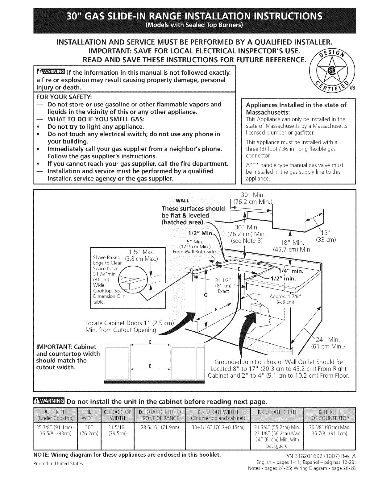
1 1/2"Max.
Shave Raised (3.8 cm Max.
Edge to Clear
Space for a
31s/_"min
(81 cm)
Wide
Cooktop.
Dimension C in
table.
Locate Cabinet Doors 1" (2.5 cm)
Min. from Cutout Opening.
iMPORTANT: Cabinet
and countertop width
should match the
cutout width.
Cabinet and 2" to 4" (5.1 cm to 10.2 cm) From Floor.
Do not install the unit in the cabinet before reading next page.
35 7/8" (91.1cm) - 31 5/16" 28 5/16" (71.9cm)
36 5/8" (93cm) (79.5cm)
NOTE: Wiring diagram for these appliances are enclosed in this booklet.
Printed in United States
30_+1/16" (76.2_+0.15cm)
" Min.
(61 cm Min.)
Grounded Box or Wall Outlet Should Be
Located 8" to 17" (20.3 cm to 43.2 cm) From Right
21 3/4" (55.2cm) Min.
22 1/8" (56.2cm) Max
24" (61cm) Min. with
backguard
P/N 318201692 (1007) Rev. A
English - pages 1-11; Espahol- p_iginas 12-23;
Notes - pages 24-25; Wiring Diagram - page 26-28
36 5/8" (93cm) Max.
35 7/8" (91.1cm)
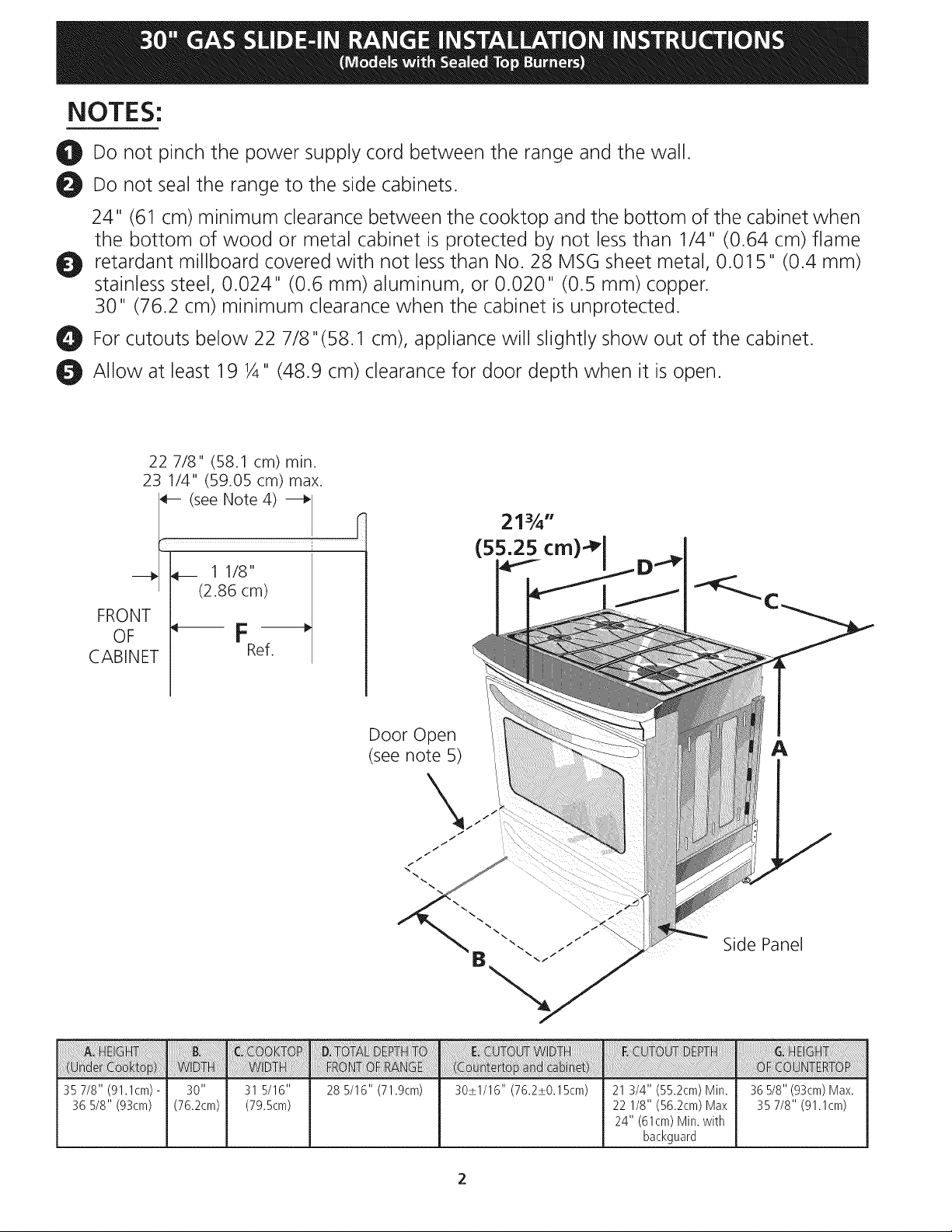
NOTES:
_! Do not pinch the power supply cord between the range and the wall.
Do not seal the range to the side cabinets.
24" (6! cm) minimum clearance between the cooktop and the bottom of the cabinet when
the bottom of wood or metal cabinet is protected by not less than 1/4" (0.64 cm) flame
Ot retardant millboard covered with not less than No. 28 MSG sheet metal, 0.015" (0.4 mm)
stainless steel, 0.024" (0.6 mm) aluminum, or 0.020" (0.5 mm) copper.
30" (76.2 cm) minimum clearance when the cabinet is unprotected.
For cutouts below 22 7/8"(58.1 cm), appliance will slightly show out of the cabinet.
Allow at least 19 ¼" (48.9 cm) clearance for door depth when it is open.
22 7/8" (58.1 cm) min.
23 1/4" (59.05 cm) max.
(see Note 4)
______ 1 1/8"
i (2.86 cm)
FRONT
OF _F -_
CABINET Ref.
S
Door Open
(see note 5)
A
Side Panel
35 7/8" (91.1cm) - 31 5/16"
36 5/8" (93cm) (79.5cm)
28 5/16" (71.9cm) 30_+1/16" (76.2_+0.15cm) 21 3/4" (55.2cm) Min.
22 1/8" (56.2cm) Max
24" (61cm) Min. with
backguard
36 5/8" (93cm) Max.
35 7/8" (91.1cm)
important Notes to the Installer
1. Read all instructions contained in these installation
instructions before installing range.
2. Remove all packing material from the oven
compartments before connecting the gas and
electrical supply to the range.
3. Observe all governing codes and ordinances.
4. Be sure to leave these instructions with the consumer.
5. Note: For operation at 2000 ft. elevations above see
level, appliance rating shall be reduced by 4 percent
for each additional 1000 ft.
important Note to the Consumer
Keep these instructions with your Use & Care Guide for
future reference.
IMPORTANT SAFETY
INSTRUCTIONS
Installation of this range must conform with local codes
or, in the absence of local codes, with the National Fuel
Gas Code ANSI Z223.1/NFPA .54-latest edition.
This range has been design certified by CSA
International. As with any appliance using gas and
generating heat, there are certain safety precautions you
should follow. You will find them in the Use and Care
Guide, read it carefully.
• Be sure your range is installed and grounded
properly by a qualified installer or service
technician.
• This range must be electrically grounded in
accordance with local codes or, in their absence,
with the National Electrical Code ANSI/NFPA No.
70--latest edition. See Grounding Instructions.
Before installing the range in an area covered
with linoleum or any other synthetic floor
covering, make sure the floor covering can
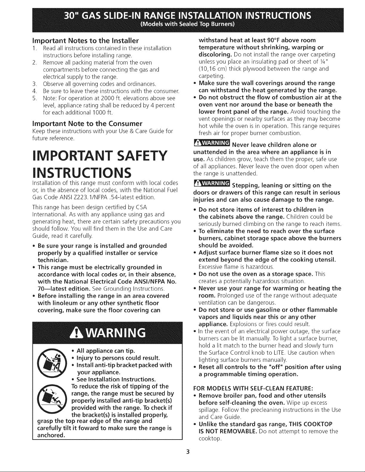
All appliance can tip.
• Injury to persons could result.
@
grasp the top rear edge of the range and
carefully tilt it foward to make sure the range is
anchored.
• Install anti-tip bracket packed with
your appliance.
See installation Instructions.
To reduce the risk of tipping of the
range, the range must be secured by
properly installed anti-tip bracket(s)
provided with the range. To check if
the bracket(s) is installed properly,
withstand heat at least 90°F above room
temperature without shrinking, warping or
discoloring. Do not install the range over carpeting
unless you place an insulating pad or sheet of 1/4"
(10,16 cm) thick plywood between the range and
carpeting.
Make sure the wall coverings around the range
can withstand the heat generated by the range.
Do not obstruct the flow of combustion air at the
oven vent nor around the base or beneath the
lower front panel of the range. Avoid touching the
vent openings or nearby surfaces as they may become
hot while the oven is in operation. This range requires
fresh air for proper burner combustion.
Never leave children alone or
unattended in the area where an appliance is in
use. As children grow, teach them the proper, safe use
of all appliances. Never leave the oven door open when
the range is unattended.
Stepping, leaning or sitting on the
doors or drawers of this range can result in serious
injuries and can also cause damage to the range.
Do not store items of interest to children in
the cabinets above the range. Children could be
seriously burned climbing on the range to reach items.
To eliminate the need to reach over the surface
burners, cabinet storage space above the burners
should be avoided.
Adjust surface burner flame size so it does not
extend beyond the edge of the cooking utensil.
Excessiveflame is hazardous.
Do not use the oven as a storage space. This
creates a potentially hazardous situation.
Never use your range for warming or heating the
room. Prolonged use of the range without adequate
ventilation can be dangerous.
Do not store or use gasoline or other flammable
vapors and liquids near this or any other
appliance. Explosions or fires could result.
In the event of an electrical power outage, the surface
burners can be lit manually. To light a surface burner,
hold a lit match to the burner head and slowly turn
the Surface Control knob to LITE.Use caution when
lighting surface burners manually.
Reset all controls to the "off" position after using
a programmable timing operation.
FOR MODELS WITH SELF-CLEAN FEATURE:
Remove broiler pan, food and other utensils
before self-cleaning the oven. Wipe up excess
spillage. Follow the predeaning instructions in the Use
and Care Guide.
Unlike the standard gas range, THIS COOKTOP
IS NOT REMOVABLE. Do not attempt to remove the
cooktop.
3
Cabinet Construction
_ To eliminate the risk of cabinet burns
and fire, do not have cabinet storage space above the
range. If there is cabinet storage space above range,
reduce risk by installing a range hood that projects
horizontally a minimum of 5" (12.7cm) beyond the
bottom of the cabinet.
| Countertop Preparation
• The cooktop sides of the range fit over the cutout
edge of your countertop.
• If you have a square finish (flat) countertop, no
countertop preparation is required. Cooktop sides lay
directly on edge of countertop.
Formed front-edged countertops must have molded
edge shaved flat 3/4" (1.9 cm) from each front corner
of opening (Figure 1).
Tile countertops may need trim cut back 3/4"(1.9 cm)
from each front corner and/or rounded edge flattened
(Figure 1).
J
311/j_
(81 cm)
water column pressure (3.5 kPa). The inlet pressure to the
regulator must be at least 1" (.25 kPa) greater than the
regulator manifold pressure setting. Examples: If regulator
is set for natural gas 4"(10,16 cm) manifold pressure, inlet
pressure must be at least 5"(12.60 cm); if regulator has
been converted for LP/Propane gas 10"(25,4 cm) manifold
pressure, inlet pressure must be at least 11"(27,9 cm).
Leak testing of the appliance shall be conducted
according to the instructions in step 4.
The gas supply line should be 1/2"or 3A" I.D. (Interior Dia.)
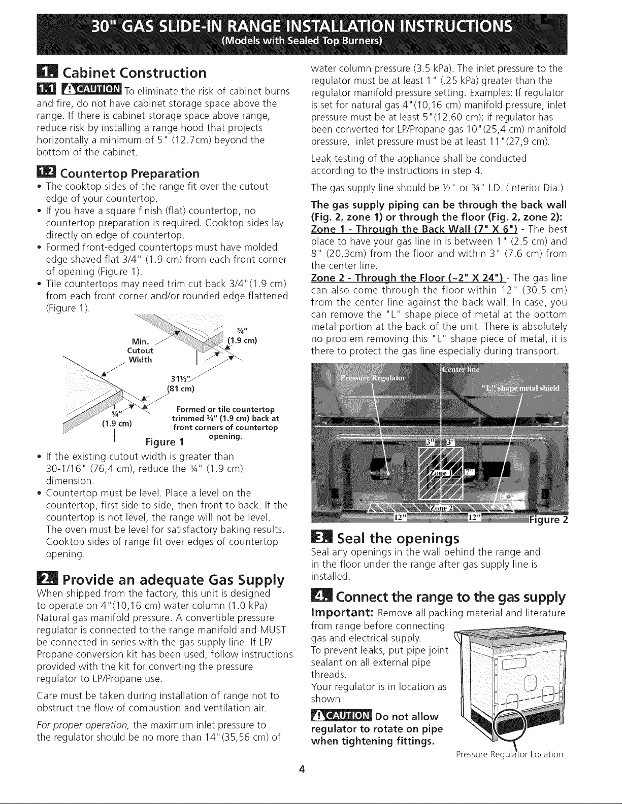
The gas supply piping can be through the back wall
(Fig. 2, zone 1) or through the floor (Fig. 2, zone 2):
Zone I - Through the Back Wall (7" X 6") - The best
place to have your gas line in is between 1" (2.5 cm) and
8" (20.3cm) from the floor and within 3" (7.6 cm) from
the center line.
Zone 2 - Through the Floor (~2" X 24") - The gas line
can also come through the floor within 12" (30.5 cm)
from the center line against the back wall. In case, you
can remove the "L" shape piece of metal at the bottom
metal portion at the back of the unit. There is absolutely
no problem removing this "L" shape piece of metal, it is
there to protect the gas line especially during transport.
Formed or tile countertop
(1.9 cm) front corners of countertop
trimmed _A" (1.9 cm) back at
I Figure I opening.
* If the existing cutout width is greater than
30-1/16" (76,4 cm), reduce the 3A" (1.9 cm)
dimension.
Countertop must be level. Place a level on the
countertop, first side to side, then front to back. If the
countertop is not level, the range will not be level.
The oven must be level for satisfactory baking results.
Cooktop sides of range fit over edges of countertop
opening.
Provide an adequate Gas Supply
When shipped from the factory, this unit is designed
to operate on 4"(10,16 cm) water column (1.0 kPa)
Natural gas manifold pressure. A convertible pressure
regulator is connected to the range manifold and MUST
be connected in series with the gas supply line. If LP/
Propane conversion kit has been used, follow instructions
provided with the kit for converting the pressure
regulator to LP/Propane use.
Care must be taken during installation of range not to
obstruct the flow of combustion and ventilation air.
For proper operation, the maximum inlet pressure to
the regulator should be no more than 14"(35,56 cm) of
Figure 2
| Seal the openings
Seal any openings in the wall behind the range and
in the floor under the range after gas supply line is
installed.
Connect the range to the gas supply
Important: Remove all packing material and literature
from range before connecting
gas and electrical supply.
To prevent leaks, put pipe joint
sealant on all external pipe
threads.
Your regulator is in location as
shown.
Do not allow
regulator to rotate on pipe
when tightening fittings.
PressureRegul Location
4
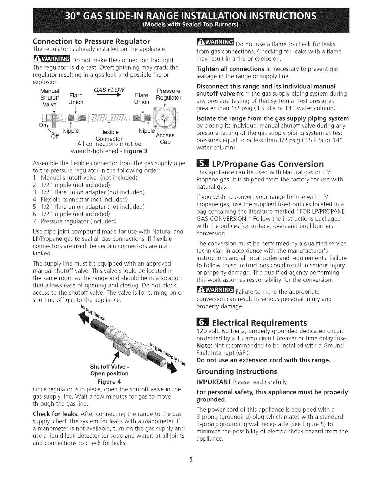
Connection to Pressure Regulator
The regulator is already installed on the appliance.
Do not make the connection too tight.
The regulator is die cast. Overtightening may crack the
regulator resulting in a gas leak and possible fire or
explosion.
Manual GAS FLOW Pressure
Shutoff Flare _" Flare Regulator
Valve Union Union
om 7 .......t ....... t
Nipple Flexible Nipple
Off Connector
All connections must be Cap
wrench-tightened - Figure 3
Access
Do not use a flame to check for leaks
from gas connections. Checking for leaks with a flame
may result in a fire or explosion.
Tighten all connections as necessary to prevent gas
leakage in the range or supply line.
Disconnect this range and its individual manual
shutoff valve from the gas supply piping system during
any pressure testing of that system at test pressures
greater than 1/2 psig (3.5 kPa or 14" water column),
Isolate the range from the gas supply piping system
by closing its individual manual shutoff valve during any
pressure testing of the gas supply piping system at test
pressures equal to or less than 1/2 psig (3.5 kPa or 14"
water column),
Assemble the flexible connector from the gas supply pipe
to the pressure regulator in the following order:
1. Manual shutoff valve (not included)
2. 1/2" nipple (not included)
3. 1/2" flare union adapter (not included)
4. Flexible connector (not included)
5. 1/2" flare union adapter (not included)
6. 1/2" nipple (not included)
7. Pressure regulator (included)
Use pipe-joint compound made for use with Natural and
LP/Propane gas to seal all gas connections. If flexible
connectors are used, be certain connectors are not
kinked.
The supply line must be equipped with an approved
manual shutoff valve. This valve should be located in
the same room as the range and should be in a location
that allows ease of opening and closing. Do not block
access to the shutoff valve. The valve is for turning on or
shutting off gas to the appliance.
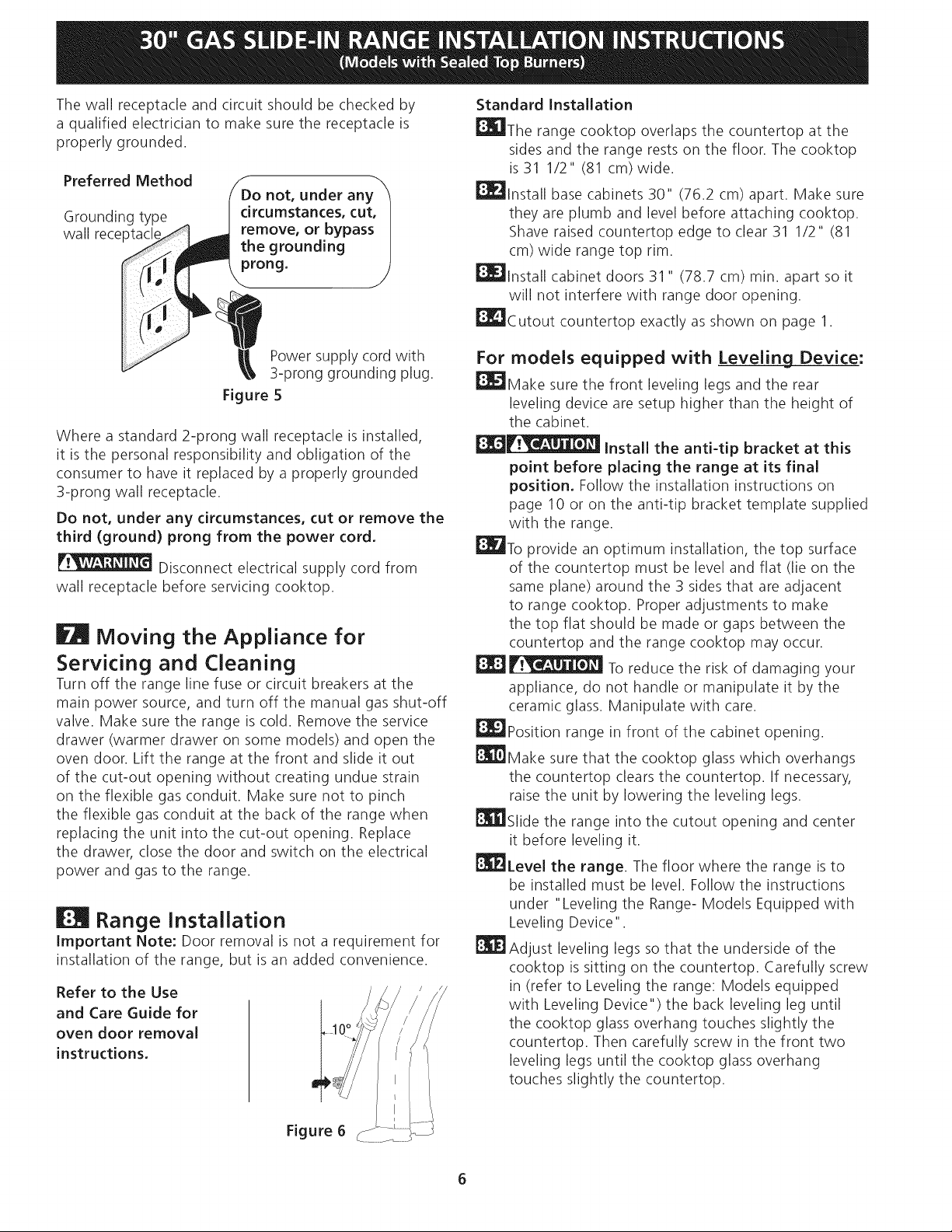
t_
Shutoff Valve =
Open position
Figure 4
Once regulator is in place, open the shutoff valve in the
gas supply line. Wait a few minutes for gas to move
through the gas line.
Check for leaks. After connecting the range to the gas
supply, check the system for leaks with a manometer. If
a manometer is not available, turn on the gas supply and
use a liquid leak detector (or soap and water) at all joints
and connections to check for leaks.
li%
| LP/Propane Gas Conversion
This appliance can be used with Natural gas or LP/
Propane gas. It is shipped from the factory for use with
natural gas.
If you wish to convert your range for use with LP/
Propane gas, use the supplied fixed orifices located in a
bag containing the literature marked "FOR LP/PROPANE
GAS CONVERSION." Follow the instructions packaged
with the orifices for surface, oven and broil burners
conversion.
The conversion must be performed by a qualified service
technician in accordance with the manufacturer's
instructions and all local codes and requirements. Failure
to follow these instructions could result in serious injury
or property damage. The qualified agency performing
this work assumes responsibility for the conversion.
Failure to make the appropriate
conversion can result in serious personal injury and
property damage.
| Electrical Requirements
120 volt, 60 Hertz, properly grounded dedicated circuit
protected by a 15 amp circuit breaker or time delay fuse.
Note: Not recommended to be installed with a Ground
Fault Interrupt (GFI).
Do not use an extension cord with this range.
Grounding Instructions
IMPORTANT Pleaseread carefully.
For personal safety, this appliance must be properly
grounded,
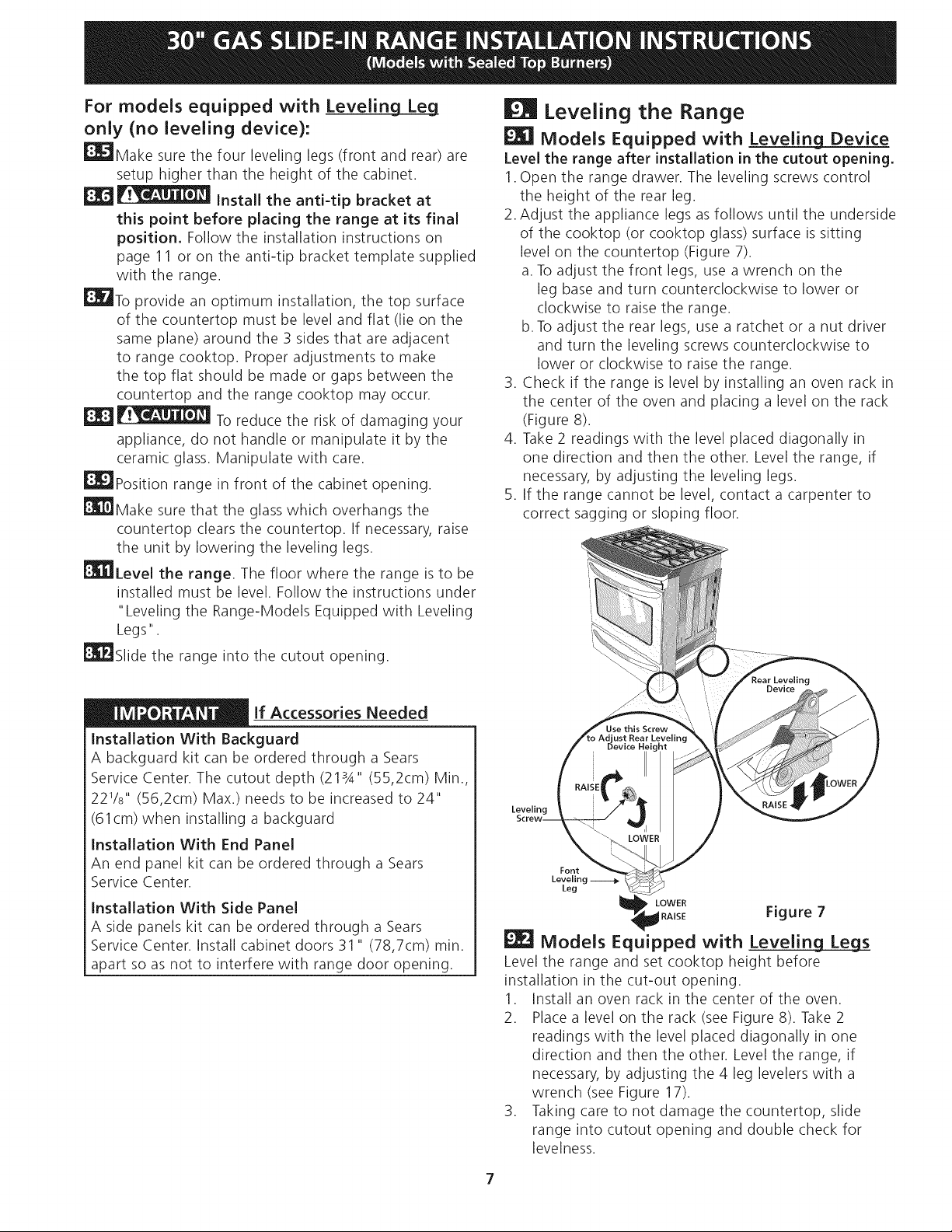
The power cord of this appliance isequipped with a
3-prong (grounding) plug which mates with a standard
3-prong grounding wall receptacle (see Figure 5) to
minimize the possibility of electric shock hazard from the
appliance,
Thewallreceptacleandcircuitshouldbecheckedby
aqualifiedelectriciantomakesurethereceptacleis
properlygrounded.
PreferredMethod
Donot,underany
Groundingtype
wallreceptacl
circumstances,cut,
remove,or bypass
thegrounding
prong.
StandardInstallation
|The rangecooktopoverlapsthecountertopatthe
sidesandtherangerestsonthefloor.Thecooktop
is311/2" (81cm)wide.
_lnstall basecabinets30"(76.2cm)apart.Makesure
theyareplumbandlevelbeforeattachingcooktop.
Shaveraisedcountertopedgeto clear311/2"(81
cm)widerangetoprim.
_lnstall cabinetdoors31" (78.7cm)min.apartsoit
willnotinterferewith rangedooropening.
_Cutout countertopexactlyasshownonpage1.
Powersupplycordwith
3-pronggroundingplug.
Figure5
Whereastandard2-prongwallreceptacleisinstalled,
it isthepersonalresponsibilityandobligationofthe
consumerto haveitreplacedbyaproperlygrounded
3-prongwallreceptacle.
Donot,underanycircumstances,cutor removethe
third (ground)prongfromthepowercord,
Disconnectelectricalsupplycordfrom
wallreceptaclebeforeservicingcooktop.
| Moving the Appliance for
Servicing and Cleaning
Turn off the range line fuse or circuit breakers at the
main power source, and turn off the manual gas shut-off
valve. Make sure the range is cold. Remove the service
drawer (warmer drawer on some models) and open the
oven door. Lift the range at the front and slide it out
of the cut-out opening without creating undue strain
on the flexible gas conduit. Make sure not to pinch
the flexible gas conduit at the back of the range when
replacing the unit into the cut-out opening. Replace
the drawer, dose the door and switch on the electrical
power and gas to the range.
| Range Installation
Important Note: Door removal is not a requirement for
installation of the range, but is an added convenience.
Refer to the Use
and Care Guide for
oven door removal
instructions.
For models equipped with Leveling Device:
_Make sure the front leveling legs and the rear
leveling device are setup higher than the height of
the cabinet.
__ Install the anti-tip bracket at this
point before placing the range at its final
position. Follow the installation instructions on
page 10 or on the anti-tip bracket template supplied
with the range.
_To provide an optimum installation, the top surface
of the countertop must be level and flat (lie on the
same plane) around the 3 sides that are adjacent
to range cooktop. Proper adjustments to make
the top flat should be made or gaps between the
countertop and the range cooktop may occur.
| _1_i_ To reduce the risk of damaging your
appliance, do not handle or manipulate it by the
ceramic glass. Manipulate with care.
_Position range in front of the cabinet opening.
|Make sure that the cooktop glass which overhangs
the countertop clears the countertop. If necessary,
raise the unit by lowering the leveling legs.
_Slide the range into the cutout opening and center
it before leveling it.
_Level the range. The floor where the range is to
be installed must be level. Follow the instructions
under "Leveling the Range- Models Equipped with
Leveling Device".
_Adjust leveling legs so that the underside of the
cooktop is sitting on the countertop. Carefully screw
in (refer to Leveling the range: Models equipped
with Leveling Device") the back leveling leg until
the cooktop glass overhang touches slightly the
countertop. Then carefully screw in the front two
leveling legs until the cooktop glass overhang
touches slightly the countertop.
Figure 6
For models equipped with Levelin Lg_Leg
only (no leveling device):
_Make sure the four leveling legs (front and rear) are
setup higher than the height of the cabinet.
_ Install the anti-tip bracket at
this point before placing the range at its final
position. Follow the installation instructions on
page 11 or on the anti-tip bracket template supplied
with the range.
_To provide an optimum installation, the top surface
of the countertop must be level and flat (lie on the
same plane) around the 3 sides that are adjacent
to range cooktop. Proper adjustments to make
the top flat should be made or gaps between the
countertop and the range cooktop may occur.
_ To reduce the risk of damaging your
appliance, do not handle or manipulate it by the
ceramic glass. Manipulate with care.
_Position range in front of the cabinet opening.
_Make sure that the glass which overhangs the
countertop dears the countertop. If necessary, raise
the unit by lowering the leveling legs.
_Level the range. The floor where the range is to be
installed must be level. Follow the instructions under
"Leveling the Range-Models Equipped with Leveling
Legs".
_Slide the range into the cutout opening.
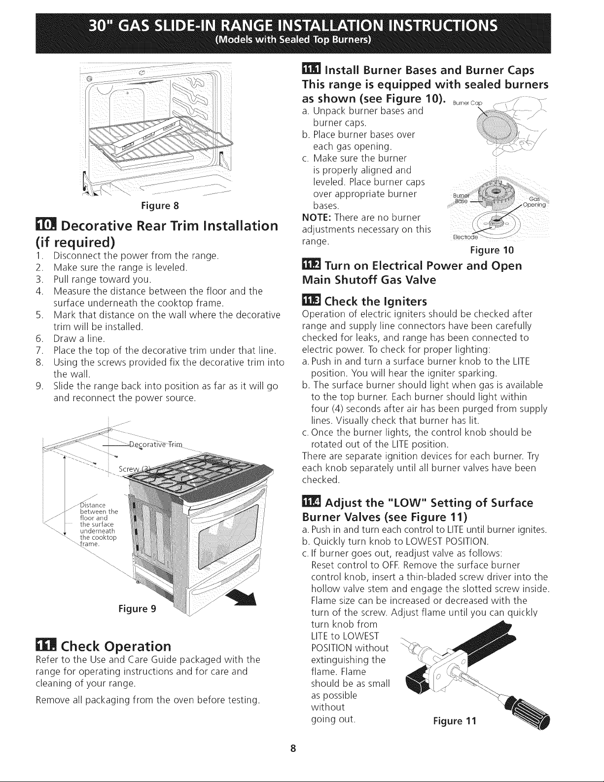
Leveling the Range
Models Equipped with Leveling Device
Level the range after installation in the cutout opening.
1.Open the range drawer. The leveling screws control
the height of the rear leg.
2. Adjust the appliance legs as follows until the underside
of the cooktop (or cooktop glass) surface is sitting
level on the countertop (Figure 7).
a. To adjust the front legs, use a wrench on the
leg base and turn counterclockwise to lower or
clockwise to raise the range.
b. To adjust the rear legs, use a ratchet or a nut driver
and turn the leveling screws counterclockwise to
lower or clockwise to raise the range.
3. Check if the range is level by installing an oven rack in
the center of the oven and placing a level on the rack
(Figure 8).
4. Take 2 readings with the level placed diagonally in
one direction and then the other. Level the range, if
necessary, by adjusting the leveling legs.
5. If the range cannot be level, contact a carpenter to
correct sagging or sloping floor.
lf Accessories Needed
Installation With Backguard
A backguard kit can be ordered through a Sears
Service Center. The cutout depth (213A'' (55,2cm) Min.,
221/8``(56,2cm) Max.) needs to be increased to 24"
(61 cm) when installing a backguard
Installation With End Panel
An end panel kit can be ordered through a Sears
Service Center.
Installation With Side Panel
A side panels kit can be ordered through a Sears
Service Center. Install cabinet doors 31 " (78,7cm) min.
apart so as not to interfere with range door opening.
ust Rear Levelin(
Leveling
Font
Leveling
Leg
LOWER
RAISE Figure 7
| Models Equipped with Leveling Leg_s
Level the range and set cooktop height before
installation in the cut-out opening.
1. Install an oven rack in the center of the oven.
2. Place a level on the rack (see Figure 8). Take 2
readings with the level placed diagonally in one
direction and then the other. Level the range, if
necessary, by adjusting the 4 leg levelers with a
wrench (see Figure 17).
3. Taking care to not damage the countertop, slide
range into cutout opening and double check for
levelness.
7
j ......................<.<:
Figure 8
Decorative Rear Trim Installation
(if required)
1. Disconnect the power from the range.
2. Make sure the range is leveled.
3. Pull range toward you.
4. Measure the distance between the floor and the
surface underneath the cooktop frame.
5. Mark that distance on the wall where the decorative
trim will be installed.
6. Draw a line.
7. Place the top of the decorative trim under that line.
8. Using the screws provided fix the decorative trim into
the wall.
9. Slide the range back into position as far as it will go
and reconnect the power source.
Install Burner Bases and Burner Caps
This range is equipped with sealed burners
as shown (see Figure 10).
a. Unpack burner bases and
burner caps.
b. Place burner bases over
each gas opening.
c. Make sure the burner
is properly aligned and
Ieveled. PIace burner caps
over appropriate burner Bu_..... .......
bases. OPening:
NOTE: There are no burner _:_
adjustments necessary on this
range.
Electrode _ .......
_as
Figure 10
Turn on Electrical Power and Open
Main Shutoff Gas Valve
mk"J Check the Igniters
Operation of electric igniters should be checked after
range and supply line connectors have been carefully
checked for leaks, and range has been connected to
electric power. Tocheck for proper lighting:
a. Push in and turn a surface burner knob to the LITE
position. You will hear the igniter sparking.
b. The surface burner should light when gas is available
to the top burner. Each burner should light within
four (4) seconds after air has been purged from supply
lines. Visually check that burner has lit.
c. Once the burner lights, the control knob should be
rotated out of the LITEposition.
There are separate ignition devices for each burner. Try
each knob separately until all burner valves have been
checked.
Check Operation
Refer to the Use and Care Guide packaged with the
range for operating instructions and for care and
cleaning of your range.
Remove all packaging from the oven before testing.
| Adjust the "LOW" Setting of Surface
Burner Valves (see Figure 11)
a. Pushin and turn each control to LITEuntil burner ignites.
b. Quickly turn knob to LOWEST POSITION.
c. If burner goes out, readjust valve asfollows:
Reset control to OFF.Remove the surface burner
control knob, insert a thin-bladed screw driver into the
hollow valve stem and engage the slotted screw inside.
Flame size can be increased or decreased with the
turn of the screw. Adjust flame until you can quickly
turn knob from
LITEto LOWEST
POSITIONwithout
extinguishing the
flame. Flame
should be as small
as possible
without
going out.
Figure 11
| Operation of Oven Burners and Oven
Adjustments
11.5.1 Electric Ignition Burners
Operation of electric igniters should be checked after
range and supply line connectors have been carefully
checked for leaks, and range has been connected to
electric power.
Theoven burner isequipped with an electric control system
aswell asan electric oven burner igniter. If your model is
equipped with a waist-high broil burner igniter, it will also
have an electric burner igniter. Thesecontrol systems require
no adjustment. When the oven is set to operate, current
will flow to the igniter. It will "glow" similar to a light bulb.
When the igniter has reached a temperature sufficient to
ignite gas, the electrically controlled oven valve will open
and flame will appear at the oven burner. There isa time
lapsefrom 30 to 60 seconds after thermostat isturned ON
before the flame appearsat the oven burner. When the oven
reachesthe display setting, the glowing igniter will go off.
The burner flame will go "out" in 20 to 30 secondsafter
igniter goes "OFF". To maintain any given oven temperature,
this cycle will continue as long asthe display isset to operate.
After removing all packing materials and literature from
the oven:
a) Set the oven to BAKE at 300% See Use & Care Guide
for operating instructions.
b) Within 60 seconds the oven burner should ignite.
Check for proper flame, and allow the burner to cycle
once. Reset controls to off.
c) If your model is equipped with a high-waist broiler,
set oven to broil. See Use & Care Guide for operating
instructions.
d) Within 60 seconds the broil burner should ignite. Check
for proper flame. Resetcontrols to off.
11.5.2 Air Shutter-Oven Burner
L wer
Oven Baffle
Shutter Burler
Waist-High
(
/
Lower Oven Bottom
Figure 12
_=-Air Shutter (removable)
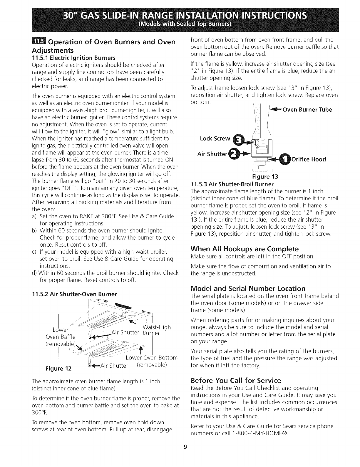
front of oven bottom from oven front frame, and pull the
oven bottom out of the oven. Remove burner baffle so that
burner flame can be observed.
If the flame isyellow, increase air shutter opening size (see
"2" in Figure 13). If the entire flame isblue, reduce the air
shutter opening size.
Toadjust frame loosen lock screw (see "3" in Figure 13),
reposition air shutter, and tighten lock screw. Replace oven
bottom.
Burner Tube
Lock Screw
Air
Shutter _ )Orifice Hood
Figure 13
11.5.3 Air Shutter-Broil Burner
The approximate flame length of the burner is 1 inch
(distinct inner cone of blue flame). Todetermine if the broil
burner flame is proper, set the oven to broil. If flame is
yellow, increase air shutter opening size (see "2" in Figure
13 ). If the entire flame is blue, reduce the air shutter
opening size. Toadjust, loosen lock screw (see "3" in
Figure 13), reposition air shutter, and tighten lock screw.
When All Hookups are Complete
Make sure all controls are left in the OFFposition.
Make sure the flow of combustion and ventilation air to
the range is unobstructed.
Model and Serial Number Location
The serial plate is located on the oven front frame behind
the oven door (some models) or on the drawer side
frame (some models).
When ordering parts for or making inquiries about your
range, always be sure to include the model and serial
numbers and a lot number or letter from the serial plate
on your range.
Your serial plate also tells you the rating of the burners,
the type of fuel and the pressure the range was adjusted
for when it left the factory.
The approximate oven burner flame length is 1 inch
(distinct inner cone of blue flame).
Todetermine if the oven burner flame is proper, remove the
oven bottom and burner baffle and set the oven to bake at
300%
Toremove the oven bottom, remove oven hold down
screws at rear of oven bottom. Pull up at rear,disengage
Before You Call for Service
Read the Before You Call Checklist and operating
instructions in your Use and Care Guide. It may save you
time and expense. The list includes common occurrences
that are not the result of defective workmanship or
materials in this appliance.
Refer to your Use & Care Guide for Sears service phone
numbers or call 1-800-4-MY-HOME®.
9
 Loading...