


23352719000
Kenmore 23352719000, 23352717000, 23352714000, 23352713000, 23352712000 Owner’s Manual
...
®
Use & Care / installation Manual
cocina
Manual de uso y cuidado /instalaci6n
Models
Modelos
233.52612000 (30" wide - White)
233.52613000 (30" wide - Stainless)
233.52614000 (30" wide - Biscuit)
233.52617000 (30" wide - Almond)
233.52619000 (30" wide - Black)
233.52712000 (36" wide - White)
233.52713000 (36" wide - Stainless)
233.52714000 (36" wide - Biscuit)
233.52717000 (36" wide - Almond)
233.52719000 (36" wide - Black)
0
u
0
Patent No,:
US D450,829 S
626987A Sears, Roebuck and Co,, Hoffman Estates, UL60179 U,S,A, www,sears,com
If within 1 year from the date of installation, any part of this
range hood fails to function properly due to a defect in mate-
rial or workmanship, Sears will repair the part or furnish and
install a new part, free of charge=
FULL 30-DAY WARRANTY ON FIN_SB ON PAINTED OR
BRIGHT METAL PARTS
Ifwithin 30 days from the date of installation, the finish on any
painted or bright metal parts of this range hood is defective in
material or workmanship, Sears will furnish and install a new
part, free of charge=
WARRANTY SERVICE iS AVAILABLE BY CONTACTING
THE NEAREST SEARS SEVICE CENTER/DEPARTMENT
iN THE UNITED STATES.
This warranty applies only while this product is in use in the
United States. This warranty gives you specific legal rights
and you may have other rights which vary from state to state.
Sears, Roebuck and Co., Oept 817WA, Hoffman Estates,
IL 6017
A iNTENDED FOR DOMESTIC COOKING ONLY A
WARNING _ A
TO REDUCE THE RiSK OF FIRE, ELECTRIC SHOCK, OR
iNJURY TO PERSONS, OBSERVE THE FOLLOWING:
1. Use this unit only in the manner intended by the manufac-
turer. If you have questions, contact the manufacturer at
the address listed in the warranty.
2. Before servicing or cleaning unit, switch power off at service
panel and lock the service disconnecting means to prevent
power from being switched on accidentally= When the
service disconnecting means cannot be locked, securely
fasten a prominent warning device, such as a tag, to the
service panel=
3. Installation work and electrical wiring must be done by a
qualified person(s)in accordance with all applicable codes
and standards, including fire-rated codes and standards=
4. Sufficient air is needed for proper combustion and
exhausting of gases through the flue (chimney) of fuel
burning equipment to prevent backdrafting. Follow the
heating equipment manufacturer's guideline and safety
standards such as those published by the National Fire
Protection Association (NFPA), and the American Society
for Heating, Refrigeration and Air Conditioning Engineers
(ASHRAE), and the local code authorities.
5. When cutting or drilling into wail or ceiling, do not damage
electrical wiring and other hidden utilities.
6. To reduce the risk of fire or electric shock, do not use this
range hood with an additional speed control device.
7. Ducted fans must always be vented to the outdoors=
8. To reduce the risk of fire, use only metal ductwork.
9. Use with approved cord-connection kit only.
10.This unit must be grounded=
TO REDUCE THE RISK OF A RANGE TOP GREASE FIRE:
1. Never leave surface units unattended at high settings.
Boilovers cause smoking and greasy sp[llovers that may
ignite. Heat oils slowly on low or medium settings=
2. Always turn hood ON when cooking at high heat or when
cooking flaming foods=
3. Clean ventilating fans frequently. Grease should not be
allowed to accumulate on fan or filter=
4. Use proper pan size. Always use cookware appropriate
for the size of the surface element= 2
WARNING _,
TO REDUCE THE RiSK OF INJURY TO PERSONS tN THE
EVENT OF A RANGE TOP GREASE FIRE, OBSERVE THE
FOLLOWING:*
1. SMOTHER FLAMES with a close-fitting lid, cookie sheet,
or metal tray, then turn off the burner= BE CAREFUL TO
PREVENT BURNS= Ifthe flames do not go out immediately,
EVACUATE AND CALL THE FIRE DEPARTMENT=
2. NEVER PICK UPA FLAMING PAN - You may be burned=
3. DO NOT USE WATER, including wet dishcloths or towels
- a v[otent steam explosion will result.
4. Use an extinguisher ONLY if:
A. You know you have a Class ABC extinguisher and you
already know how to operate it.
B. The fire is small and contained in the area where it
started=
C. The fire department is being called.
D. You can fight the fire with your back to an exit=
* Based on "Kitchen Firesafety Tips" published by NFPA.
CAUTION A
1. For general ventilating use only. Do not use to exhaust
hazardous or explosive materials and vapors=
2. To avoid motor bearing damage and noisy and/or
unbalanced impellers, keep drywall spray, construction
dust, etc. off power unit.
3. For best capture of cooking impurities, your range hood
should be mounted so that the top of the hood is 24-30"
above the cooking surface=
4. Use only with range hood cord-connection kits that have
been investigated and found acceptable for use with this
model range hood=
5. Please read specification label on product for further
information and requirements.
tf hood is to be installed Non-Ducted:
,_ Purchase a set of (2) non-ducted filters from your
moca_distributor or retailer and attach them to the
aluminum mesh filters.
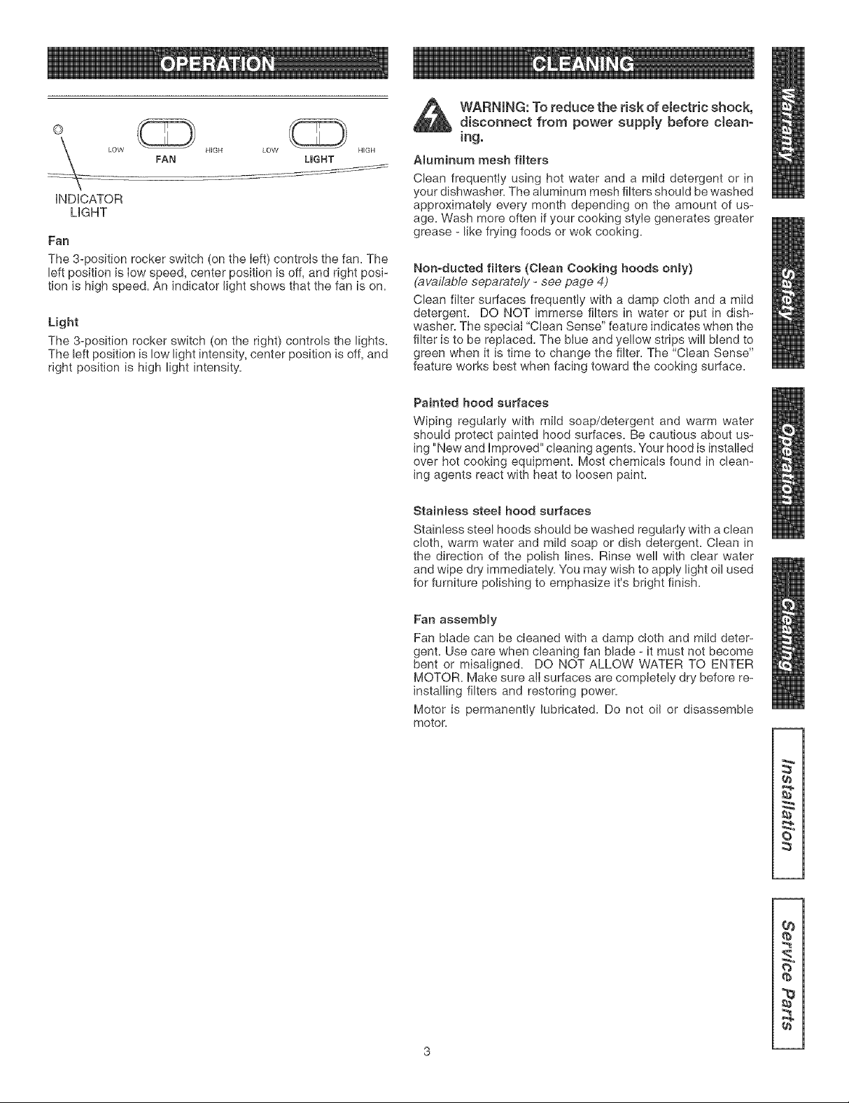
©
LOW HIGH LOW HIGH
FAN LIGHT
iNDiCATOR
LIGHT
Fan
The 3-position rocker switch (on the left) controls the fan. The
left position is Iow speed, center position is off, and right posi-
tion is high speed. An indicator light shows that the fan is on.
Light
The 3-position rocker switch (on the right) controls the lights.
The left position is low light intensity, center position is off, and
right position is high light intensity.
WARNING: To reduce the risk of electric shock,
disconnect from power supply before cJean-
rag.
ABuminum mesh filters
Clean frequently using hot water and a mild detergent or in
your dishwasher. The aluminum mesh filters should be washed
approximately every month depending on the amount of us-
age. Wash more often if your cooking style generates greater
grease - like frying foods or wok cooking.
Nonoducted filters (Cmean Cooking hoods onmy)
(available separately - see page 4)
Clean filter surfaces frequently with a damp cloth and a mild
detergent. DO NOT immerse filters in water or put in dish-
washer. The special "Clean Sense" feature indicates when the
filter is to be repIaced. The blue and yel!ow strips will blend to
green when it is time to change the filter. The "Clean Sense"
feature works best when facing toward the cooking surface.
Painted hood surfaces
Wiping regularly with mild soap/detergent and warm water
should protect painted hood surfaces. Be cautious about us-
ing "New and improved" cleaning agents. Your hood is installed
over hot cooking equipment. Most chemicaIs found in clean-
ing agents react with heat to loosen paint.
Stainless steem hood surfaces
Stainless steel hoods should be washed regularIy with a clean
cloth, warm water and mild soap or dish detergent. Clean in
the direction of the polish Iines. Rinse well with clear water
and wipe dry immediately. You may wish to apply light oil used
for furniture polishing to emphasize it's bright finish.
Fan assembmy
Fan blade can be cleaned with a damp cloth and mild deter-
gent. Use care when cleaning fan blade - it must not become
bent or misaIigned. DO NOT ALLOW WATER TO ENTER
MOTOR. Make sure alI surfaces are completely dry before re-
installing filters and restoring power.
Motor is permanently lubricated. Do not oil or disassemble
motor.
q_
{b
q_
2
3

7-inch Round
Duct Adapter
Light Bumb
(2 per hood)
Sears Part No. 57853
31A" × 10-
Damper/Duct Connector
Aluminum Grease Filter
(2 per hood)
Parts Bag
(4 hood mounting screws inside)
OPTmONAL PARTS (purchase separately)
Clean Cooking Filters
(Non-ducted hoods only)
(2 per hood)
Sears Part Nos. 50191 (30")
50192 (36")
7-inch Round Damper
(For use with 7-inch Round Duct)
Sears Part No, 59183
Splashplate
Sears Part Nos,
58120 30" Black/Biscuit
58128 30" White/Almond
58130 36" Black/Biscuit
58138 36" White/Almond
Cord Kit
(Allows hood to be plugged into a
standard 120 VAC wall outlet)
Sears Part No, 233,22HCK44D
Ducting Accessories
(See "Equivalent Duct Length Chart" on page 5 for Ducting
Accessory Model Nos.
1
"Parts Not Included With Hood" avaimabte by calming |
Sears at 1-800_4-MY-HOME _
!
/ / Q /
Screwdriver Tape !/4"
(Fmat& Phillips) Pencil Measure Nutdriver
Sabre Keyhole Wire
Drill Saw -or= Saw Duct Tape Stripper
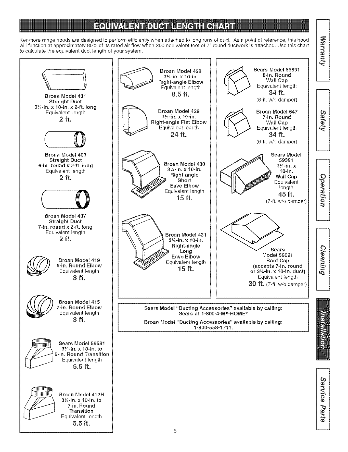
KenmorerangehoodsaredesignedtoperformefficientlywhenattachedtoIongrunsofduct.Asapointofreference,thishood
wiIIfunctionatapproximately80%ofitsratedairftowwhen200equivalentfeetof7"roundductworkisattached.Usethischart
tocalculatetheequivalent duct length of your system.
Broan Modem 401
Straight Duct
3¼=in, x lO-in, × 2=ft, mong
Equivalent length
2ft.
( 0
Broan Modem406
Straight Duct
64n. round × 2-ft, long
Equivalent length
2 ft.
( 0
Broan Modem 407
Straight Duct
7-in. round × 2-ft. long
EquivaIent Iength
2 ft.
Broan Modem419
64n, Round Elbow
Equivalent length
8 ft.
Broan Modem415
7-in, Round Elbow
Equivalent length
8 ft.
Sears Model 59581
3¼-in, x lO-in, to
6=in. Round Transition
Equivalent length
5.5 ft.
Broan Model 412H
3¼=in, x lO-in, to
7=inoRound
Transition
Equivalent Iength
5.5 ft.
Broan Model 428
3¼-in° x lO=in.
Right=angBe Embow
Equivalent Iength
8.5 ft.
D Broan _'1odel 429
3¼-in. x lO-ino
Right-angle Fiat Elbow
Equivalent length
24 ft.
Broan Model 430
3¼-in. x lO-ino
Right-angme
Short
Eave E{bow
quivalent length
15 ft.
Broan Model 431
3¼-in, x lO-in.
Right-angle
Long
Eave Elbow
quivalent length
15 ft.
_ Sears Modem59691
8=in° Round
Wall Cap
Equivalent length
34 ft.
(6-ft=w/o damper)
(_ Broan Modem647
74n. Round
Wall Cap
Equivalent length
34 ft.
(6-ft=w/o damper)
Sears Model
59391
3¼=in. x
lO-in,
Wall Cap
Equivalent
length
45 ft.
(7-ft= w/o damper)
Model 59091
Roof Cap
(accepts 74n. round
or 3¼-in. × lO-in, duct}
Equivalent Iength
30 ft. (7-fL W/Odamper)
Sears Modet "Ducting Accessories" avaHabmeby calling:
Sears at 1-800-4-MY_HOME _
Broan Modet "Ducting Accessories" availabme by calling:
1_800=558=1711°
{b
re
t_
2
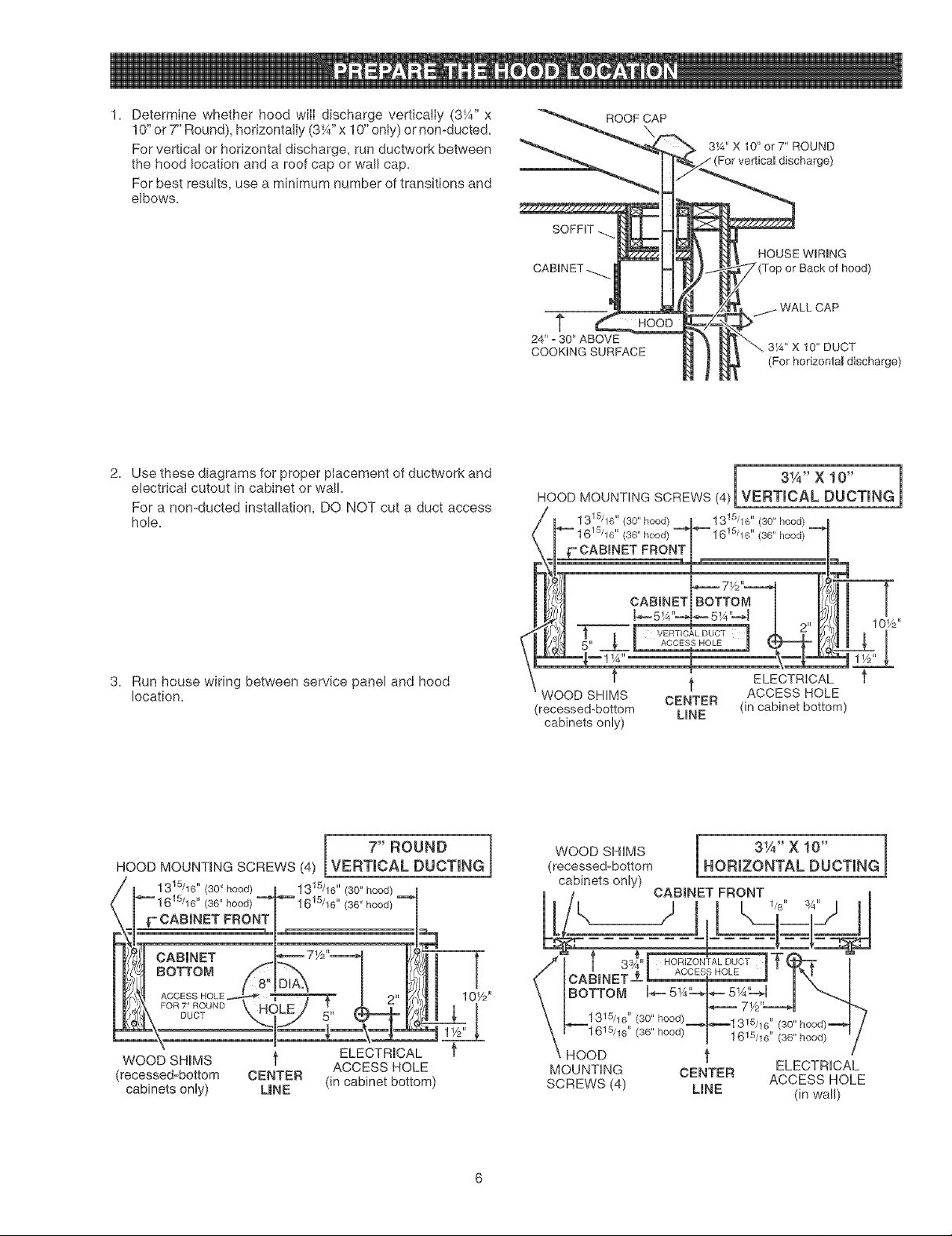
1. Determine whether hood wilI discharge vertically (3¼" x
10" or7" Round), horizontally (3V4"x 10" only) or nomducted.
For vertical or horizontal discharge, run ductwork between
the hood location and a roof cap or wall cap.
For best results, use a minimum number of transitions and
elbows.
ROOF CAP
31A'X 10" or 7" ROUND
For vertical discharge)
HOUSE WIRING
or Back of hood)
t
24" =30" ABOVE
COOKINGSURFACE
3W' X 10" DUCT
(For horizontal discharge)
2. Use these diagrams for proper placement of ductwork and
electrical cutout in cabinet or wall.
For a nomducted installation, DO NOT cut a duct access
hole.
3. Run house wiring between service panel and hood
location.
3¼"X 10" 1
HOOD MOUNTING SCREWS (4)reVERT CAL DUCT NG
1 315/16 `' (30" hood) 1315/16 `' 30" hood
(36" hood) _ 15/ .... --"_ 16 16 (36 hood)
,F"CABINET FRONT
71/2"===._
CABINET BOTTOM
J_-...-5W'-_ ,..=5W_4
T _t VERTICAL DUCT 2'_m
_E 11S_" ACCESSHOLE
ELECTRICAL
ACCESS HOLE
WOOD SHIMS CENTER
(recessed-bottom LINE (in cabinet bottom)
cabinets only)
- i
I 7" ROUND
HOOD MOUNTmNGSCREWS (4) [VERTICAL DUCTING
1315/16"(30" hood)
_""- 1615/16 '' (36" hood)
I
,_ 2"
\
WOOD SHMS t ELECTRm_;AL
ACCESS HOLE
(recessed=bottom CENTER (in cabinet bottom)
cabinets only) L|NE
WOOD SHIMS l 31A" X 10" ]
(recessed-bottom HORIZONTAL DUCTING
cabinets only)
CABBNET FRONT
HOOD _'
ELECTRICAL
MOUNTING CENTER ACCESS HOLE
SCREWS (4) UNE (in wall)
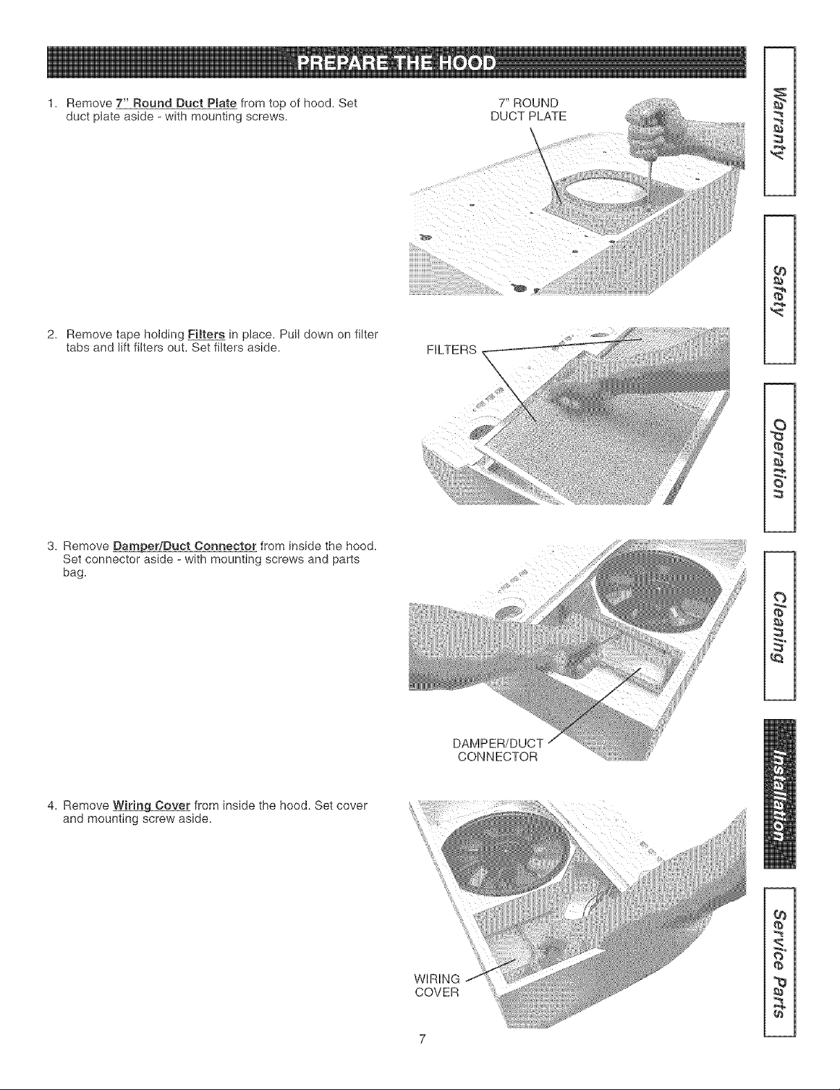
Remove 7" Round Duct Pmatefrom top of hood. Set
duct plate aside - with mounting screws=
7" ROUND
DUCT PLATE
\
2.
Remove tape holding Filters in place. Pull down on filter
tabs and lift filters out. Set filters aside.
FILTERS
3. Remove Damper/Duct Connector from inside the hood.
Set connector aside - with mounting screws and parts
bag.
CONNECTOR
¢e
S"
4. Remove WiringCover from inside the hood. Set cover
and mounting screw aside.
WiRiNG
COVER
O_
q_
q_
7
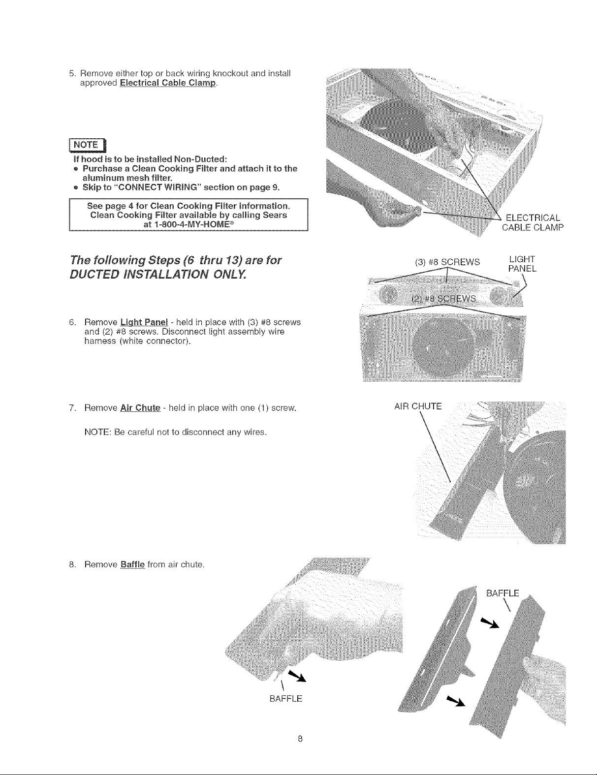
5. Remove either top or back wiring knockout and install
approved Electricam Cabme CmamJo,
/
if hood is to be installed Non-Ducted:
e Purchase a CmeanCooking Fimter and attach it to the
aluminum mesh filtero
e Skip to "CONNECT WiRiNG" section on page 9,
See page 4 for Cmean Cooking Filter information.
Clean Cooking Fimter available by calling Sears
at 1-800o4-MY-HOME ®
ELECTRICAL
CABLE CLAMP
The following Steps (6 thru 13) are for
DUCTED INSTALLATION ONLY.
(3) #8 SCREWS LIGHT
PANEL
6.
Remove _ht Panel - held in place with (3) #8 screws
and (2) #8 screws. Disconnect light assembly wire
harness (white connector).
7. Remove Air Chute - held in place with one (1) scre_
NOTE: Be careful not to disconnect any wires.
AiR CHUTE
\
\
\
8. Remove Baffle from air chute.
BAFFLE
BAFFLE
\
 Loading...