

Page 1

www.tek.com/keithley
Model 2182/2182A Nanovoltmeter
User’s Manual
2182A-900-01 Rev. B / May 2017
Page 2

WARRANTY
Keithley Instruments warrants this product to be free from defects in material and workmanship for a
period of one (1) year from date of shipment.
Keithley Instruments warrants the following items for 90 days from the date of shipment: probes,
cables, software, rechargeable batteries, diskettes, and documentation.
During the warranty period, Keithley Instruments will, at its option, either repa
proves to be defective.
To exercise this warranty, write or call your local Keithley Instruments representative, or contact
Keithley Instrument
return instructions. Send the product, transportation prepaid, to the indicated service facility. Repairs
will be made and the product returned, transportation prepaid. Repaired or replaced products are
warranted for the balance of the original warranty period, or at least 90 days.
s headquarters in Cleveland, Ohio. You will be given prompt assistance and
LIMITATION OF WARRANTY
This warranty does not apply to defects resulting from product modification without Keithley
Instruments’ express written consent, or misuse of any product or part. This warranty also does not
apply to fuses, software, non-rechargeable batteries, damage from battery leakage, or problems
arising from normal wear or failure to follow instructions.
ir or replace any product that
THIS WARRANTY IS IN LIEU OF ALL OTHER WARRANTIES, EXPRE
INCLUDING ANY IMPLIED WARRANTY OF MERCHANTABILITY OR FITNESS FOR A
PARTICULAR USE. THE REMEDIES PROVIDED HEREIN ARE THE BUYER’S SOLE AND
EXCLUSIVE REMEDIES.
NEITHER KEITHLEY INSTRUMENTS NOR ANY OF ITS EMPLOYEES SHALL BE LIABLE FOR
ANY DIRECT, INDIRECT, SPECIAL, INCIDENTAL, OR CONSEQUENTIAL DAMAGES ARISING
OUT OF THE USE OF ITS INSTRUMENTS AND SOFTWARE, EVEN IF KEITHLEY
INSTRUMENTS HAS BEEN ADVISED IN ADVANCE OF THE POSSIBILITY OF SUCH
DAMAGES. SUCH EXCLUDED DAMAGES SHALL INCLUDE, BUT ARE NOT LIMITED TO: COST
OF REMOVAL AND INSTALLATION, LOSSES SUSTAINED AS THE RESULT OF INJURY TO ANY
PERSON, OR DAMAGE TO PROPERTY.
Keithley Instruments
Corporate Headquarters • 28775 Aurora Road • Cleveland, Ohio 44139
440-248-0400 • Fax: 440-248-6168 • 1-800-KEITHLEY (1-800-935-5595) • www.tek.com/keithley
SSED OR IMPLIED,
3/07
Page 3

Model 2182 and 2182A Nanovoltmeter
User’
This User’s Manual supports both the Models 2182 and 2182A:
References to the Model 2182 apply to both the Models 2182 and 2182A.
References to the Model 2182/2182A apply to the Model 2182 with firmaware version A10
or higher, and the Model 2182A with firmware version C01 or higher.
References to the Model 2182A applies to the Model 2182A with firmware version C01 or
higher.
s Manual
©2017, Keithley Instruments
All rights reserved.
Cleveland, Ohio, U.S.A.
First Printing, June 2004
Document Number: 2182A-900-01 Rev. B
Page 4

Manual Print History
The print history shown below lists the printing dates of all Revisions and Addenda created
for this manual. The Revision Level letter increases alphabetically as the manual undergoes
subsequent updates. Addenda, which are released between Revisions, contain important change
information that the user should incorporate immediately into the manual. Addenda are
numbered sequentially. When a new Revision is created, all Addenda associated with the
previous Revision of the manual are incorporated into the new Revision of the manual. Each new
Revision includes a revised copy of this print history page.
Revision A (Document Number 2182A-900-01) ............................................................. June 2004
Revision B (Document Number 2182A-900-01) ............................................................. May 2017
All Keithley product names are trademarks or registered trademarks of Keithley Instruments.
Other brand names are trademarks or registered trademarks of their respective holders.
Page 5

Safety Precautions
The following safety precautions should be observed before using this product and any associated instrumentation.
Although some instruments and accessories would normally be used with non-hazardous voltages, there are
situations where hazardous conditions may be present.
This product is intended for use by qualified personnel who recognize shock hazards and are familiar with the safety
precautions required to avoid possible injury. Read and follow all installation, operation, and maintenance
information carefully before using the product. Refer to the user documentation for complete product specifications.
If the product is used in a manner not specified, the protection provided by the product warranty may be impaired.
The types of product users are:
Responsible body is the individual or group responsible for the use and maintenance of equipment, for ensuring
that the equipment is operated within its specifications and operating limits, and for ensuring that operators are
adequately trained.
Operators use the product for its intended function. They must be trained in electrical safety procedures and proper
use of the instrument. They must be protected from electric shock and contact with hazardous live circuits.
Maintenance personnel perform routine procedures on the product to keep it operating properly, for example,
setting the line voltage or replacing consumable materials. Maintenance procedures are described in the user
documentation. The procedures explicitly state if the operator may perform them. Otherwise, they should be
performed only by service personnel.
Service personnel are trained to work on live circuits, perform safe installations, and repair products. Only properly
trained service personnel may perform installation and service procedures.
Keithley Instruments products are designed for use with electrical signals that are rated Measurement Category I
and Measurement Category II, as described in the International Electrotechnical Commission (IEC) Standard IEC
60664. Most measurement, control, and data I/O signals are Measurement Category I and must not be directly
connected to mains voltage or to voltage sources with high transient over-voltages. Measurement Category II
connections require protection for high transient over-voltages often associated with local AC mains connections.
Assume all measurement, control, and data I/O connections are for connection to Category I sources unless
otherwise marked or described in the user documentation.
Exercise extreme caution when a shock hazard is present. Lethal voltage may be present on cable connector jacks
or test fixtures. The American National Standards Institute (ANSI) states that a shock hazard exists when voltage
levels greater than 30V RMS, 42.4V peak, or 60VDC are present. A good safety practice is to expect that hazardous
voltage is present in any unknown circuit before measuring.
Operators of this product must be protected from electric shock at all times. The responsible body must ensure that
operators are prevented access and/or insulated from every connection point. In some cases, connections must be
exposed to potential human contact. Product operators in these circumstances must be trained to protect
themselves from the risk of electric shock. If the circuit is capable of operating at or above 1000 volts, no conductive
part of the circuit may be exposed.
Do not connect switching cards directly to unlimited power circuits. They are intended to be used with impedancelimited sources. NEVER connect switching cards directly to AC mains. When connecting sources to switching cards,
install protective devices to limit fault current and voltage to the card.
Before operating an instrument, make sure the line cord is connected to a properly grounded power recep tacle.
Inspect the connecting cables, test leads, and jumpers for possible wear, cracks, or breaks before each use.
When installing equipment where access to the main power cord is restricted, such as rack mounting, a separate
main input power disconnect device must be provided in close proximity to the equipment and within easy reach of
the operator.
11/07
Page 6

For maximum safety, do not touch the product, test cables, or any other instruments while power is applied to the
!
circuit under test. ALWAYS remove power from the entire test system and discharge any capacitors before:
connecting or disconnecting cables or jumpers, installing or removing switching cards, or making internal changes,
such as installing or removing jumpers.
Do not touch any object that could provide a current path to the common side of the circuit under test or power line
(earth) ground. Always make measurements with dry hands while standing on a dry, insulated surface capable of
withstanding the voltage being measured.
The instrument and accessories must be used in accordance with specifications and operating instructions, or the
safety of the equipment may be impaired.
Do not exceed the maximum signal levels of the instruments and accessories, as defined in the specifications and
operating information, and as shown on the instrument or test fixture panels, or switching card.
When fuses are used in a product, replace with the same type and rating for continued protection against fire hazard.
Chassis connections must only be used as shield connections for measuring circuits, NOT as safety earth ground
connections.
If you are using a test fixture, keep the lid closed while power is applied to the device under test. Safe operation
requires the use of a lid interlock.
If a screw is present, connect it to safety earth ground using the wire recommended in the user documentation.
The symbol on an instrument indicates that the user shoul d refer to the operating instructions located in the
documentation.
The symbol on an instrument shows that it can source or measure 1000 volts or more, including the combined
effect of normal and common mode voltages. Use standard safety precautions to avoid personal contact with these
voltages.
The symbol on an instrument shows that the surface may be hot. Avoid personal contact to prevent burns.
The symbol indicates a connection terminal to the equipment frame.
If this symbol is on a product, it indicates that mercury is present in the display lamp. Please note that the lamp
must be properly disposed of according to federal, state, and local laws.
The WARNING heading in the user documentation explains dangers that might result in personal injury or death.
Always read the associated information very carefully before performing the indicated procedure.
The CAUTION heading in the user documentation explains hazards that could damage the instrument. Such
damage may invalidate the warranty.
Instrumentation and accessories shall not be connected to humans.
Before performing any maintenance, disconnect the line cord and all test cables.
To maintain protection f rom elect ric shoc k and fi re, replacement components in mains circuits - including the power
transformer, test leads, and input jacks - must be purchased from Keithley Instruments. Standard fuses with
applicable national safety approvals may be used if the rating and type are the same. Other components that are
not safety-related may be purchased from other suppliers as long as they are equivalent to the original component
(note that selected parts should be purchased only through Keithley Instruments to maintain accuracy and
functionality of the product). If you are unsure about the applicability of a replacement component, call a Keithley
Instruments office for information.
T o clean an instrument, use a damp cloth or mild, water-based cleaner . Clean the exterior of the instrument only . Do
not apply cleaner directly to the instrument or allow liquids to enter or spill on the instrument. Products that consist
of a circuit board with no case or chassis (e.g., data acquisition board for installation into a computer) should never
require cleaning if handled according to instructions. If the board becomes contaminated and operation is affected,
the board should be returned to the factory for proper cleaning/servicing.
Page 7

Table of Contents
1 Getting Started
General information
Warranty information ....................................................................................... 1-3
Contact information ......................................................................................... 1-3
Safety symbols and terms ................................................................................ 1-3
Inspection ......................................................................................................... 1-3
Options and accessories ................................................................................... 1-4
Nanovoltmeter features ........................................................................................... 1-6
Front and rear panel familiarization ........................................................................ 1-7
Front panel summary ....................................................................................... 1-7
Rear panel summary ...................................................................................... 1-11
Cleaning input connectors ..................................................................................... 1-13
Power-Up .............................................................................................................. 1-14
Line power connection ................................................................................... 1-14
Setting line voltage and replacing fuse .......................................................... 1-15
Power-up sequence ........................................................................................ 1-15
Line frequency ............................................................................................... 1-16
Display .................................................................................................................. 1-16
Status and error messages .............................................................................. 1-16
Default settings ..................................................................................................... 1-16
................................................................................................ 1-3
2 Voltage and Temperature Measurements
Measurement overview
Voltage measurements ..................................................................................... 2-3
Temperature measurements ............................................................................. 2-3
Performance considerations .................................................................................... 2-5
Warm-up .......................................................................................................... 2-5
ACAL (calibration) .......................................................................................... 2-5
Autozeroing modes .......................................................................................... 2-6
LSYNC (line cycle synchronization) ............................................................... 2-8
Pumpout current (low charge injection mode) ................................................. 2-9
SCPI programming - ACAL, Front Autozero, Autozero, LSYNC, and
Low Charge Injection .................................................................................. 2-10
Connections ........................................................................................................... 2-12
Connection techniques ................................................................................... 2-12
Voltage only connections ............................................................................... 2-14
Temperature only connections ....................................................................... 2-15
Voltage and temperature connections ............................................................ 2-16
Cleaning test circuit connectors ..................................................................... 2-17
........................................................................................... 2-3
Page 8

Temperature configuration
Measuring voltage and temperature ..................................................................... 2-19
SCPI programming - voltage and temperature measurements ...................... 2-20
Low-level considerations ...................................................................................... 2-22
Thermal EMFs ............................................................................................... 2-22
Noise .............................................................................................................. 2-22
Applications .......................................................................................................... 2-23
Low-resistance measurements ....................................................................... 2-23
Standard cell comparisons ............................................................................. 2-26
Heated Zener Reference and Josephson Junction Array comparisons .......... 2-27
................................................................................... 2-18
3 Range, Digits, Rate, and Filter
Range ......................................................................................................................
Maximum readings .......................................................................................... 3-3
Manual ranging ............................................................................................... 3-3
Autoranging ..................................................................................................... 3-4
SCPI programming - range ............................................................................. 3-4
Digits ...................................................................................................................... 3-5
SCPI programming - digits ............................................................................. 3-5
Rate ......................................................................................................................... 3-6
SCPI programming - rate ................................................................................ 3-7
Filter ....................................................................................................................... 3-8
Analog filter .................................................................................................... 3-8
Digital filter ..................................................................................................... 3-8
SCPI programming - filter ............................................................................. 3-12
4 Relative, mX+b, and Percent (%)
Relative ...................................................................................................................
REL Key .......................................................................................................... 4-3
SCPI programming - relative ......................................................................... 4-4
mX+b and percent (%) ........................................................................................... 4-6
mX+b ............................................................................................................... 4-6
Percent (%) ...................................................................................................... 4-7
SCPI programming - mX+b and percent ......................................................... 4-8
5 Ratio and Delta
3-3
4-3
Ratio .......................................................................................................................
Basic procedure ............................................................................................... 5-2
Filter, Rel, and Ranging considerations .......................................................... 5-4
Delta ....................................................................................................................... 5-6
Selecting Delta ................................................................................................ 5-9
Delta measurement procedure using a SourceMeter ....................................... 5-9
Filter considerations ...................................................................................... 5-15
5-2
Page 9

SCPI programming - ratio and delta
Programming examples ................................................................................. 5-16
Applications .......................................................................................................... 5-18
Testing superconductor materials .................................................................. 5-19
6 Buffer
..................................................................... 5-16
Buffer operations
Store ................................................................................................................. 6-2
Recall ............................................................................................................... 6-3
Buffer statistics ................................................................................................ 6-4
SCPI programming - buffer .................................................................................... 6-5
Programming example ..................................................................................... 6-6
7 Triggering
Trigger model
Idle ................................................................................................................... 7-3
Control source and event detection .................................................................. 7-4
Delay ................................................................................................................ 7-4
Device action ................................................................................................... 7-5
Output trigger ................................................................................................... 7-5
Reading hold (autosettle) ........................................................................................ 7-6
Hold example ................................................................................................... 7-6
External triggering .................................................................................................. 7-7
External trigger ................................................................................................ 7-8
Voltmeter complete .......................................................................................... 7-8
External triggering example ............................................................................. 7-9
External triggering with BNC connections .................................................... 7-12
SCPI programming - triggering ............................................................................ 7-13
Trigger model (remote operation) .................................................................. 7-13
Trigger model operation ................................................................................ 7-15
Triggering commands .................................................................................... 7-16
Programming example ................................................................................... 7-17
..................................................................................................... 6-2
.......................................................................................................... 7-3
8 Limits
Limit operations
Setting limit values .......................................................................................... 8-4
Enabling limits ................................................................................................. 8-4
SCPI programming - limits ..................................................................................... 8-5
Application .............................................................................................................. 8-7
Sorting resistors ............................................................................................... 8-7
...................................................................................................... 8-3
Page 10

9 Stepping and Scanning
10
Step/Scan overview
Internal Stepping/Scanning (Channels 1 and 2) .............................................. 9-3
External Stepping/Scanning ............................................................................ 9-3
Front panel trigger models ...................................................................................... 9-4
Internal scanning ............................................................................................. 9-4
Other Stepping/Scanning operations ............................................................... 9-6
Stepping/Scanning controls .................................................................................... 9-6
Step/Scan configuration .................................................................................. 9-7
Stepping/Scanning examples .................................................................................. 9-8
Internal scanning ............................................................................................. 9-8
Internal stepping .............................................................................................. 9-9
External scanning .......................................................................................... 9-10
SCPI programming - stepping and scanning ........................................................ 9-12
Programming example .................................................................................. 9-13
Application — I-V curves using internal scan ..................................................... 9-14
SCAN for IV curves [Measure V, sweep I, constant H (magnetic field)
or T (temperature)] ..................................................................................... 9-14
................................................................................................ 9-3
Analog Output
Overview ..............................................................................................................
Operation .............................................................................................................. 10-5
Analog output connections ............................................................................ 10-5
Configure and control analog output ............................................................. 10-5
Analog output rel ........................................................................................... 10-5
SCPI programming - analog output ...................................................................... 10-6
Programming example .................................................................................. 10-6
10-3
11
Remote Operation
Selecting and configuring an interface
Interfaces ....................................................................................................... 11-3
Languages ...................................................................................................... 11-3
Interface selection and configuration procedures .......................................... 11-4
GPIB operation and reference .............................................................................. 11-6
GPIB bus standards ....................................................................................... 11-6
GPIB bus connections ................................................................................... 11-6
Primary address selection .............................................................................. 11-8
QuickBASIC programming ........................................................................... 11-8
General bus commands ................................................................................. 11-9
Front panel GPIB operation ........................................................................ 11-12
Status structure ............................................................................................ 11-13
Programming syntax ................................................................................... 11-21
................................................................. 11-3
Page 11

RS-232 interface reference
Sending and receiving data .......................................................................... 11-27
Baud rate, flow control and terminator ........................................................ 11-27
RS-232 connections ..................................................................................... 11-29
Error messages ............................................................................................. 11-30
.................................................................................. 11-27
12
13
Common Commands
*CLS — Clear Status Clear status registers and error queue
*ESE <NRf> – Event Enable Program the standard event enable register ... 12-4
*ESE? – Event Enable Query Read the standard event register .................... 12-4
*ESR? – Event Status Register Query Read register and clear it .................. 12-6
*IDN? – Identification Query Read the identification code .......................... 12-7
*OPC – Operation Complete Set the OPC bit in the standard
event register after all pending commands are complete ............................ 12-8
*OPC? – Operation Complete Query Place a “1” in the output
queue after all pending operations are completed ..................................... 12-10
*RCL – Recall Return to setup stored in memory ....................................... 12-11
*RST – Reset Return 2182 to *RST defaults .............................................. 12-12
*SAV – Save Save present setup in memory ............................................... 12-12
*SRE <NRf> – Service Request Enable Program service request
enable register ........................................................................................... 12-12
*SRE? – Service Request Enable Query Read service request
enable register ........................................................................................... 12-12
*STB? – Status Byte Query Read status byte register ................................. 12-14
*TRG – Trigger Send bus trigger to 2182 ................................................... 12-15
*TST?– Self-Test Query Run self test and read result ................................ 12-15
*WAI – Wait-to-Continue Prevent execution of commands until
previous commands are completed ........................................................... 12-16
........................ 12-3
SCPI Signal Oriented Measurement Commands
14
:CONFigure:<function> .................................................................................
:FETCh? ......................................................................................................... 13-3
:READ? .......................................................................................................... 13-3
:MEASure:<function>? ................................................................................. 13-4
SCPI Reference Tables
13-2
Page 12

15
Additional SCPI Commands
DISPlay subsystem
:TEXT commands ......................................................................................... 15-3
FORMat subsystem .............................................................................................. 15-4
:DATA command .......................................................................................... 15-4
:BORDer command ....................................................................................... 15-6
:ELEMents command .................................................................................... 15-6
STATus subsystem ............................................................................................... 15-7
[:EVENt]? command .................................................................................... 15-7
:ENABle command ..................................................................................... 15-11
:CONDition? command ............................................................................... 15-13
:PRESet command ....................................................................................... 15-14
:QUEue commands ..................................................................................... 15-14
:SYSTem subsystem ........................................................................................... 15-16
:PRESet command ....................................................................................... 15-16
Performance commands .............................................................................. 15-16
:BEEPer command ...................................................................................... 15-18
:KCLick command ...................................................................................... 15-18
:POSetup <name> command ...................................................................... 15-18
:VERSion? command .................................................................................. 15-19
:ERRor? command ...................................................................................... 15-19
:CLEar command ........................................................................................ 15-19
:KEY <NRf> command ............................................................................. 15-20
A Specifications
............................................................................................... 15-3
B Status and Error Messages
C Measurement Considerations
Measurement considerations
Thermoelectric potentials ................................................................................ C-2
Thermoelectric generation ............................................................................... C-3
Source resistance noise .................................................................................... C-4
Magnetic fields ................................................................................................ C-6
Radio frequency interference .......................................................................... C-6
Ground loops ................................................................................................... C-6
Shielding .......................................................................................................... C-8
Meter loading .................................................................................................. C-9
.................................................................................. C-2
Page 13

D Model 182 Emulation Commands
E Example Programs
Program examples
Changing function and range .......................................................................... E-2
One-shot triggering ......................................................................................... E-4
Generating SRQ on buffer full ........................................................................ E-5
Storing readings in buffer ............................................................................... E-6
Taking readings using the :READ? command ................................................ E-7
Controlling the Model 2182 via the RS-232 COM2 port ............................... E-8
.................................................................................................. E-2
F IEEE-488 Bus Overview
Introduction .............................................................................................................
Bus description ........................................................................................................ F-2
Bus lines .................................................................................................................. F-4
Data lines ......................................................................................................... F-4
Bus management lines ..................................................................................... F-4
Handshake lines ............................................................................................... F-5
Bus commands ........................................................................................................ F-6
Uniline commands ........................................................................................... F-7
Universal multiline commands ........................................................................ F-8
Addressed multiline commands ....................................................................... F-9
Address commands .......................................................................................... F-9
Unaddress commands ...................................................................................... F-9
Common commands ...................................................................................... F-10
SCPI commands ............................................................................................. F-10
Command codes ............................................................................................. F-10
Typical command sequences ......................................................................... F-11
IEEE command groups .................................................................................. F-12
Interface function codes ........................................................................................ F-13
F-2
G IEEE-488 and SCPI Conformance Information
Introduction ............................................................................................................
H Measurement Queries
:FETCh? .................................................................................................................
What it does .................................................................................................... H-2
Limitations ...................................................................................................... H-2
Where appropriate ........................................................................................... H-2
:READ? .................................................................................................................. H-2
What it does .................................................................................................... H-2
Limitations ...................................................................................................... H-3
When appropriate ............................................................................................ H-3
G-2
H-2
Page 14

:MEASure[:<function>]? ......................................................................................
What it does .................................................................................................... H-3
Limitations ..................................................................................................... H-3
When appropriate ........................................................................................... H-3
[:SENSe[1]]:DATA:FRESh? ................................................................................ H-4
What it does .................................................................................................... H-4
Limitations ..................................................................................................... H-4
When appropriate ........................................................................................... H-4
[:SENSe[1]]:DATA[:LATest]? ............................................................................. H-4
What it does .................................................................................................... H-4
Limitations ..................................................................................................... H-4
When appropriate ........................................................................................... H-4
Examples ............................................................................................................... H-5
One-shot reading, DC volts, no trigger, fastest rate ....................................... H-5
One-shot reading, DC volts, bus trigger, auto ranging ................................... H-5
One-shot reading, external trigger, auto delay enabled .................................. H-5
H-3
I Delta, Pulse Delta, and Dif
Overview .................................................................................................................
Keithley instrumentation requirements ............................................................ I-2
Operation overview .......................................................................................... I-3
Test system configurations ...................................................................................... I-5
Delta measurement process ..................................................................................... I-6
Pulse Delta process .................................................................................................. I-9
Pulse Delta measurements ................................................................................ I-9
Pulse Delta outputs ......................................................................................... I-11
Differential Conductance process .......................................................................... I-14
Differential Conductance calculations ........................................................... I-16
ferential Conductance
I-2
Page 15

List of Illustrations
1 Getting Started
Figure 1-1
Figure 1-2 Model 2182 rear panel ...................................................................................... 1-11
Figure 1-3 Power module ................................................................................................... 1-14
Model 2182 front panel ....................................................................................... 1-7
2 Voltage and Temperature Measurements
Figure 2-1
Figure 2-2 Model 2107 input cable .................................................................................... 2-13
Figure 2-3 LEMO connector - terminal identification ....................................................... 2-13
Figure 2-4 Connections - single channel voltage ............................................................... 2-14
Figure 2-5 Connections - dual channel voltage .................................................................. 2-15
Figure 2-6 Connections - temperature (internal reference) ................................................ 2-15
Figure 2-7 Connections - temperature (simulated reference) ............................................. 2-16
Figure 2-8 Connections - voltage and temperature (internal reference) ............................. 2-16
Figure 2-9 Connections - voltage and temperature (simulated reference) ......................... 2-17
Figure 2-10 4-Wire low-resistance measurement technique ................................................ 2-23
Figure 2-11 Measuring switch contact resistance ................................................................. 2-24
Figure 2-12 Measuring switch contact resistance and temperature ...................................... 2-25
Figure 2-13 Standard cell comparison measurements .......................................................... 2-26
Figure 2-14 Heated Zener characterization .......................................................................... 2-27
Line cycle synchronization ................................................................................. 2-8
3 Range, Digits, Rate, and Filter
Figure 3-1
Figure 3-2 Moving and repeating filters ............................................................................. 3-10
Speed vs. noise characteristics ............................................................................ 3-6
5 Ratio and Delta
Figure 5-1
Figure 5-2 Delta measurement using bipolar source ............................................................ 5-8
Figure 5-3 Delta measurement connections ....................................................................... 5-11
Figure 5-4 Triggering timing diagram ................................................................................ 5-14
Figure 5-5 Calibrating 1:10 divider .................................................................................... 5-18
Figure 5-6 Test circuit—Fixed I (Vary H) ......................................................................... 5-20
Figure 5-7 H-V Curve (Fixed I) ......................................................................................... 5-21
Figure 5-8 SourceMeter output—2-point custom sweep ................................................... 5-21
Figure 5-9 I-V Curve (Fixed H) ......................................................................................... 5-22
Figure 5-10 Test circuit—Fixed H (Vary I) ......................................................................... 5-23
Figure 5-11 SourceMeter output—30-point custom sweep ................................................. 5-25
Figure 5-12 Trigger link connections using two Model 2182s ............................................ 5-26
Test circuit using constant current source ........................................................... 5-7
Page 16

6 Buffer
Figure 6-1
Buffer locations .................................................................................................. 6-3
7 Triggering
Figure 7-1
Figure 7-2 Device action ...................................................................................................... 7-5
Figure 7-3 Rear panel pinout ............................................................................................... 7-7
Figure 7-4 Trigger link input pulse specifications (EXT TRIG) ......................................... 7-8
Figure 7-5 Trigger link output pulse specifications (VMC) ................................................ 7-8
Figure 7-6 DUT test system ................................................................................................. 7-9
Figure 7-7 Trigger link connections .................................................................................... 7-9
Figure 7-8 Operation model for triggering example .......................................................... 7-10
Figure 7-9 DIN to BNC trigger cable ................................................................................ 7-12
Figure 7-10 Trigger model (remote operation) .................................................................... 7-13
Front panel trigger model (without Stepping/Scanning) .................................... 7-3
8 Limits
Figure 8-1
Figure 8-2 Setup to test 10Ω resistors
Figure 8-3 Limits to sort 10Ω resistors (1%, 5%, and >5%) ............................................... 8-8
Default limits ...................................................................................................... 8-3
.................................................................................. 8-7
9 Stepping and Scanning
Figure 9-1
Figure 9-2 Front panel triggering (other step/scan operations) ........................................... 9-5
Figure 9-3 External scanning example with Model 7001 .................................................. 9-11
Figure 9-4 Waveform to be programmed into Model 2400 ............................................... 9-14
Figure 9-5 Setup of Model 2182 and Model 2400 ............................................................. 9-15
Front panel triggering (internal scanning) .......................................................... 9-5
11
Figure 11-1
Figure 11-2 IEEE-488 connections ...................................................................................... 11-7
Figure 11-3 IEEE-488 connector location ........................................................................... 11-7
Figure 11-4 Model 2182 status model structure ................................................................ 11-14
Figure 11-5 Standard event status ...................................................................................... 11-16
Figure 11-6 Operation event status .................................................................................... 11-16
Figure 11-7 Measurement event status .............................................................................. 11-17
Figure 11-8 Questionable event status ............................................................................... 11-17
Figure 11-9 Status byte and service request ...................................................................... 11-19
Figure 11-10 RS-232 interface connector ............................................................................ 11-29
Remote Operation
IEEE-488 connector ......................................................................................... 11-6
Page 17

12
Common Commands
Figure 12-1
Figure 12-2 Standard event status register ........................................................................... 12-7
Figure 12-3 Service request enable register ....................................................................... 12-13
Figure 12-4 Status byte register .......................................................................................... 12-15
15
Figure 15-1
Figure 15-2 IEE754 single precision data format (32 data bits) ........................................... 15-5
Figure 15-3 IEEE754 double precision data format (64 data bits) ....................................... 15-5
Figure 15-4 Measurement event register .............................................................................. 15-8
Figure 15-5 Questionable event register ............................................................................... 15-9
Figure 15-6 Operation event register .................................................................................. 15-10
Figure 15-7 Measurement event enable register ................................................................. 15-12
Figure 15-8 Questionable event enable register ................................................................. 15-12
Figure 15-9 Operation event enable register ...................................................................... 15-13
Figure 15-10 Key-press codes .............................................................................................. 15-21
Standard event enable register .......................................................................... 12-5
Additional SCPI Commands
ASCII data format ............................................................................................. 15-4
C Measurement Considerations
Figure C-1
Figure C-2 Power line ground loops .................................................................................... C-7
Figure C-3 Eliminating ground loops .................................................................................. C-7
Figure C-4 Shielding example .............................................................................................. C-8
Figure C-5 Meter loading ..................................................................................................... C-9
Thermal EMF generation ................................................................................... C-3
F IEEE-488 Bus Overview
Figure F-1
Figure F-2 IEEE-488 handshake sequence ........................................................................... F-5
Figure F-3 Command codes .................................................................................................. F-8
I Delta, Pulse Delta and Dif
Figure I-1
Figure I-2 Test system configurations .................................................................................. I-5
Figure I-3 Delta measurement technique ............................................................................. I-6
Figure I-4 Pulse Delta 3-point measurement technique ....................................................... I-9
Figure I-5 Pulse timing ...................................................................................................... I-12
Figure I-6 Pulse sweep output examples ........................................................................... I-13
Figure I-7 Differential Conductance measurement process ............................................... I-15
IEEE-488 bus configuration ................................................................................ F-3
ferential Conductance
Delta, Pulse Delta, and Differential Conductance measurements ...................... I-4
Page 18

Page 19

List of T
1 Getting Started
ables
Table 1-1
Table 1-2 Factory defaults ................................................................................................. 1-17
Fuse ratings ....................................................................................................... 1-15
2 Voltage and Temperature Measurements
Table 2-1
Table 2-2 SCPI commands - ACAL, Front Autozero, Autozero, LSYNC, and
Table 2-3 SCPI commands - voltage and temperature measurements .............................. 2-20
Measurement channels ........................................................................................ 2-3
Low Charge Injection .................................................................................. 2-10
3 Range, Digits, Rate, and Filter
Table 3-1
Table 3-2 SPCI commands - digits ..................................................................................... 3-5
Table 3-3 SCPI commands - rate ........................................................................................ 3-7
Table 3-4 SCPI commands - filter ..................................................................................... 3-12
SPCI commands - range ..................................................................................... 3-4
4 Relative, mX+b, and Percent (%)
Table 4-1
Table 4-2 SCPI commands - mX+b and percent ................................................................ 4-8
SCPI commands - relative .................................................................................. 4-4
5 Ratio and Delta
Table 5-1
SCPI commands - ratio and delta ..................................................................... 5-16
6 Buffer
Table 6-1
SCPI commands - buffer ..................................................................................... 6-5
7 Triggering
Table 7-1
Table 7-2 SCPI commands - triggering ............................................................................. 7-16
Auto delay times ................................................................................................. 7-4
8 Limits
Table 8-1
SCPI commands - limits ..................................................................................... 8-5
9 Stepping and Scanning
Table 9-1
SCPI commands - stepping and scanning ......................................................... 9-12
Page 20

10
Analog Output
Table 10-1
Table 10-2 SCPI commands - analog output ...................................................................... 10-6
11
Table 11-1
Table 11-2 RS-232 connector pinout ................................................................................ 11-29
Table 11-3 PC serial port pinout ....................................................................................... 11-30
12
Table 12-1
13
Table 13-1
14
Table 14-1
Table 14-2 CALibration command summary (user accessible) ......................................... 14-4
Table 14-3 DISPlay command summary ............................................................................ 14-5
Table 14-4 FORMat command summary ........................................................................... 14-5
Table 14-5 OUTPut command summary ............................................................................ 14-6
Table 14-6 ROUTe command summary ............................................................................ 14-6
Table 14-7 SENSe command summary .............................................................................. 14-7
Table 14-8 STATus command summary .......................................................................... 14-11
Table 14-9 SYSTem command summary ........................................................................ 14-12
Table 14-10 TRACe command summary ........................................................................... 14-12
Table 14-11 Trigger command summary ........................................................................... 14-13
Table 14-12 UNIT command summary .............................................................................. 14-14
Analog output examples* ................................................................................. 10-3
Remote Operation
General bus commands and associated statements .......................................... 11-9
Common Commands
IEEE-488.2 common commands and queries .................................................. 12-2
SCPI Signal Oriented Measurement Commands
Signal oriented measurement command summary .......................................... 13-2
SCPI Reference Tables
CALCulate command summary ....................................................................... 14-3
B Status and Error Messages
Table B-1
Status and error messages .................................................................................. B-2
C Measurement Considerations
Table C-1
Material thermoelectric coefficients ................................................................... C-2
D Model 182 Emulation Commands
Table D-1
Model 182 device-dependent command summary ............................................ D-2
Page 21

F IEEE-488 Bus Overview
Table F-1
Table F-2 Hexadecimal and decimal command codes ...................................................... F-10
Table F-3 Typical addressed bus sequence ........................................................................ F-11
Table F-4 Typical addressed common command sequence .............................................. F-11
Table F-5 IEEE command groups ..................................................................................... F-12
Table F-6 Model 2182 interface function codes ................................................................ F-13
IEEE-488 bus command summary ..................................................................... F-7
G IEEE-488 and SCPI Conformance Information
Table G-1
Table G-2 Coupled commands ........................................................................................... G-3
IEEE-488 documentation requirements ............................................................. G-2
Page 22

Page 23

Getting
Started
Getting
1
Started
Page 24

1-2
Getting Started
NOTE This User’s Manual supports both the Models 2182 and 2182A:
References to the Model 2182 apply to both the Models 2182 and 2182A.
References to the Model 2182/2182A apply to the Model 2182 with firmaware version A10 or higher, and the Model 2182A with firmware version C01 or higher.
References to the Model 2182A applies to the Model 2182A with firmware version
C01 or higher.
• General information — Covers general information that includes warranty
information, contact information, safety symbols and terms, inspection, and a
vailable
options and accessories.
• Nanovoltmeter features — Summarizes the features of the Model 2182.
• Front and rear panel familiarization — Summarizes the controls and connectors of
the instrument.
• Cleaning input connector terminals — Explains ho
w to clean the contacts of the input
LEMO connectors.
• Power
-Up — Covers line power connection, line voltage setting, fuse replacement, and
the power-up sequence.
• Display — Provides information about the display of the Model 2182.
• Default settings — Co
vers the two instrument setup configurations available to the user;
user defined or factory default.
Page 25

General information
Warranty information
Warranty information is located at the front of this manual. Should your Model 2182 require
warranty service, contact the Keithley representative or authorized repair facility in your area for
further information. When returning the instrument for repair, be sure to fill out and include the
service form at the back of this manual to provide the repair facility with the necessary
information.
Contact information
Worldwide phone numbers are listed at the front of this manual. If you have any questions,
please contact your local Keithley representative or call one of our Application Engineers at
1-800-348-3735 (U.S. and Canada only).
Safety symbols and terms
The following symbols and terms may be found on the instrument or used in this manual:
!
The symbol on an instrument indicates that the user should refer to the operating
instructions located in the manual.
The symbol on an instrument shows that high voltage may be present on the terminal(s).
Use standard safety precautions to avoid personal contact with these voltages.
Getting Started
1-3
The WARNING heading used in this manual explains dangers that might result in personal
injury or death.
indicated procedure.
The CAUTION heading used in this manual explains hazards that could damage the
instrument. Such damage may in
Inspection
The Model 2182 was carefully inspected electrically and mechanically before shipment.
After unpacking all items from the shipping carton, check for any obvious signs of physical
damage that may have occurred during transit. (There may be a protective film over the display
lens, which can be removed). Report any damage to the shipping agent immediately. Save the
original packing carton for possible future shipment. The following items are included with
every Model 2182 order:
Always read the associated information very carefully before performing the
validate the warranty.
• Model 2182 Nanovoltmeter with line cord.
• Model 2107-4 Input Cable.
•Four alligator clips that attach to the copper lugs of the Model 2107 Input Cable.
• DeoxIt copper cleaning solution.
• Accessories as ordered.
• Certificate of calibration.
• Model 2182 User’s Manual (P/N 2182-900-00).
• Model 2182 Service Manual (P/N 2182-902-00).
• Manual Addenda (pertains to any improvements or changes concerning the instrument
or manual.
Page 26

1-4
Getting Started
If an additional manual is required, order the appropriate manual package. The manual
packages include a manual and any pertinent addenda.
Options and accessories
The following options and accessories are available from Keithley for use with the
Model 2182.
Cables, connectors, and adapters
Models 2107-4 and 2107-30 Input Cable — Connect the Model 2182 Nanovoltmeter to
DUT using one of these input cables. The input cable is terminated with a LEMO connector (for
connection to the Model 2182) on one end and four copper spade lugs (for connection to DUT)
on the other. The Model 2107-4 (which is a supplied accessory to the Model 2182) is 1.2m (4 ft)
in length and the Model 2107-30 is 9m (30 ft) in length. Also included are four copper alligator
clips that attach to the copper lugs of the cable, and DeoxIt copper cleaning solution.
Model 2182-KIT Low Thermal Connector — Consists of a lo
and strain relief. Includes all the connector parts required to build a custom input cable for the
Model 2182 Nanovoltmeter.
Model 2187-4 Input Cable — Low-thermal input cable for the Model 2182/2182A. Terminated with a LEMO connector on one end and four banana plugs on the other
(1.2m) in length.
Model 2188 Low-Thermal Calibration Shorting Plug — This input shorting plug is
required to calibrate the Model 2182 Nano
Models 7007-1 and 7007-2 Shielded GPIB Cables — Connect the Model 2182 to the GPIB
bus using shielded cables and connectors to reduce electromagnetic interference (EMI).
Model 7007-1 is 1m long; the Model 7007-2 is 2m long.
Model 7009-5 Shielded RS-232 Cable — 1.5m (5 ft) RS-232 cable terminated with a male
DB-9 connector on one end and a female DB-9 connector on the other end. It is wired as a
straight through (not null modem) cable.
Models 8501-1 and 8501-2 Trigger Link Cables — Connect the Model 2182 to other
instruments with
1 is 1m long; the Model 8501-2 is 2m long.
Model 8502 Trigger Link Adapter — Lets you connect an
the Model 2182 to instruments that use the standard BNC trigger connectors.
Model 8503 DIN to BNC Trigger Cable — Lets you connect Trigger Link lines one
(V
oltmeter Complete) and two (External Trigger) of the Model 2182 to instruments that use
BNC trigger connectors. The Model 8503 is 1m long.
Trigger Link connectors (e.g., Model 7001 Switch System). The Model 8501-
voltmeter.
w-thermal LEMO connector
. The cable is 4 ft
The
y of the six Trigger Link lines of
Silver solder
2182-325A — Use this Keithley part number to order a 20-foot length of silver solder. Also
included is an MSDS sheet listing the solder chemical contents.
Page 27

Getting Started
Rack mount kits
Model 4288-1 Single Fixed Rack Mount Kit — Mounts a single Model 2182 in a standard
19-inch rack.
1-5
Model 4288-2 Side-by-Side Rack Mount Kit — Mounts tw
486, 487, 2000, 2001, 2002, 2010, 2182, 2400, 2410, 2420, 6517, 7001) side-by-side in a
standard 19-inch rack.
Model 4288-4 Side-by-Side Rack Mount Kit — Mounts a Model 2182 and a 5.25-inch
instrument (Models 195A, 196, 220, 224, 230, 263, 595, 614, 617, 705, 740, 775, etc.)
side-by-side in a standard 19-inch rack.
o instruments (Models 182, 428,
Carrying case
Model 1050 Padded Carrying Case — A carrying case for a Model 2182. Includes handles
and shoulder strap.
Page 28

1-6
Getting Started
Nanovoltmeter features
The Model 2182 is a 71⁄2-digit high-performance digital nanovoltmeter. It has two input
channels to measure voltage and temperature. The measurement capabilities of the Model 2182
are explained in Section 2 of this manual (see “Measurement overview”).
Features of the Model 2182 Nanovoltmeter include:
• Ratio — Provides comparison readings between two voltage inputs. Ratio performs
V1/V2.
• Delta — Provides average difference of Channel 1 inputs. Delta performs
(V1t1–V1t2)/2.
• Enhanced Delta, Pulse Delta, and Differential Conductance — The following tests
can be performed when using a Model 2182/2182A with a Model 6220 or 6221 Current
Source:
— Delta - Uses a square w
the effects of thermal EMFs.
— Pulse Delta (6221 and 2182A only) - Provides a pulse output and a 3-point (or
2-point) measurement algorithm for testing of temperature sensiti
Test (DUT).
— Differential Conductance - Uses a dif
average algorithm to perform differential measurements.
• mX+b and Percent — These calculations provide mathematical manipulation of
readings.
• Relative — Null offsets or establish baseline values.
• Buffer — Store up to 1024 readings in the internal buffer.
• Limits — Set high and low reading limits to test devices.
• Internal Scanning — Scan the two input channels of the Model 2182.
• External Scanning — Scan the channels or matrix points of K
switching cards.
• Setup Storage — Two instrument setups (user and factory defaults) can be saved and
recalled.
• Analog Output —
1V analog output.
• Remote Interface — The Model 2182 can be controlled using the IEEE-488 interface
(GPIB) or the RS-
• GPIB Programming Language — When using the GPIB, the instrument can be
programmed using the SCPI or Model 182 (DDCs) programming language.
• Closed-cover Calibration — The Model 2182 can be calibrated from either the front
panel or the GPIB.
With analog output gain set to one, a full range input will result in a
232 interface.
ave output and a 3-point measurement algorithm to cancel
ve Device Under
ferential current output and a 3-point moving
eithley Model 7001/7002
Page 29
Front and rear panel familiarization
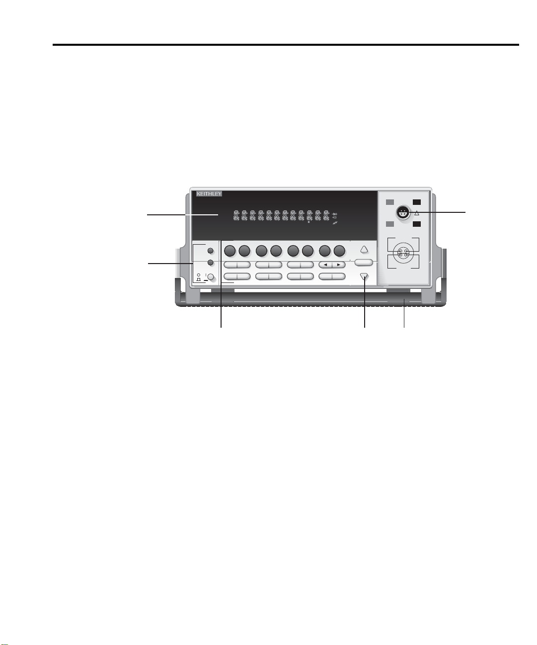
Front panel summary
The front panel of the Model 2182 is shown in Figure 1-1. This figure includes important
abbreviated information that should be reviewed before operating the instrument.
Figure 1-1
Model 2182 front panel
SCAN
CH1REM
STEP CH2 CH3 CH4 CH5 CH6 CH7 CH8 CH9 CH10
TALK
LSTN
4
1
POWER
SRQ
SHIFT
TIMER
HOLD TRIG FAST MED SLOW AUTO ERR
%
MX+B
SHIFT
DCV1
DCV2
HOLD
DELAY
LOCAL
EX TRIG
TRIG
CONFIG HALT
STEP SCAN
V1-V
2
L
ACAL
1/V2
V
BUFFER
STORE
RECALL
SETUP
SAVE RESTR
REL FILT
SYNC
TYPE
OUTPUT
FILT REL
LIMITS
ON/OFFVALUE
RS232
GPIB
DIGITS RATE
MATH
REAR
4W
BUFFER
STAT
2182 NANOVOLTMETER
A
OUT
TCOUPL
TEMP
TEMP
1
CAL TEST
EXIT ENTER
Getting Started
CHANNEL 1
LO
HI
!
HI
LO
CHANNEL 2
120V MAX
2
RANGE
AUTO
RANGE
12V MAX
CAT I
350V PEAK ANY
TERMINAL TO CHASSIS
1-7
5
236
NOTE Most keys provide a dual function or operation. The nomenclature on a key indicates
its unshifted function/oper
ation, which is selected by pressing the key. Nomenclature
(in blue) above a key indicates its shifted function. A shifted function is selected by
pressing the SHIFT key and then the function/operation key.
1 Special keys and power switch
SHIFT Use to select a shifted function or operation.
LOCAL Cancels GPIB remote mode.
POWER Power switch. In position turns 2182 on (1), out position turns it off (0).
Page 30

1-8
Getting Started
2 Function and operation keys
Top Row
Un-shifted
DCV1 Selects Channel 1 voltage measurement function.
DCV2 Selects Channel 2 voltage measurement function.
V1/V2 Selects Ratio (Channel 1 voltage reading / Channel 2 voltage reading).
ACAL Selects automatic gain calibration.
FILT Enables/disables filter for selected measurement function.
REL Enables/disables relative for selected measurement function.
TEMP1 Selects Channel 1 temperature measurement function.
TEMP2 Selects Channel 2 temperature measurement function.
Shifted
MX+B Multiplies a scale factor (M) to the reading (X) and then adds an offset (B).
% Calculates percent deviation from a specified reference.
V1-V2 Selects Delta; (V1t1 – V1t2)/2.
LSYNC Enables/disables line cycle synchronization. When enabled, noise induced
by the power line is reduced at the expense of speed.
TYPE Select filter (analog and/or digital) and configure digital filter (window,
count and type).
OUTPUT Enables/disables relative for Analog Output.
A
OUT
Enables/disables Analog Output.
TCOUPL Configure temperature measurement (units, junction type, thermocouple
type, sensor type).
Middle Row
Un-shifted
EX-TRIG Selects external triggering (front panel, bus or trigger link) as trigger
source.
TRIG Triggers a measurement from the front panel.
STORE Sets reading count for buffer and enables buffer.
RECALL Displays stored readings (including maximum, minimum, peak-to-peak,
average, and standard deviation). The and range keys scroll through
the b
uffer, and the and key toggles between reading number and
reading.
VALUE
Set the upper and lower limits for limit testing.
ON/OFF Enables/disables limit testing, and selects beeper mode for limit testing.
and Controls cursor position for making selections or editing values.
Shifted
DELAY Sets user delay between trigger and measurement.
HOLD Holds reading when the specified number of samples is within the selected
tolerance.
Page 31

Getting Started
Bottom Row
Un-shifted
STEP Steps through channels; sends a trigger after each channel.
SCAN Scans through channels; sends a trigger after last channel.
SAVE Saves present configuration for power-on user default.
RESTR Restores factory or user default configuration.
DIGITS Changes number of digits of reading resolution.
RATE Changes reading rate; number of power line cycles (PLC).
EXIT Cancels selection, moves back to measurement display.
ENTER Accepts selection, moves to next choice or back to measurement display.
Shifted
CONFIG Configures a scan (type, timer, channel count, and reading count).
HALT Turns off step/scan operation.
GPIB Enables/disables GPIB, sets address, and selects language.
RS232 Enables/disables RS-232 interface, selects baud rate, flow control, and
terminator.
CAL Accesses calibration.
TEST Tests display annunciators and front panel keys.
1-9
3 Range keys
Selects the next higher voltage measurement range.
Selects the next lower voltage measurement range.
AUTO Enables/disables autorange.
Page 32

1-10
Getting Started
4 Display annunciators
* (asterisk) Readings being stored in buffer.
↔ (more) Indicates additional selections are available.
))
(speaker) Beeper on for limit testing.
)
AUTO Autorange enabled.
BUFFER Recalling readings stored in buffer.
CH1 Channel 1 input displayed.
CH2 Channel 2 input displayed.
CH1 and CH2 Ratio (V1/V2) reading displayed.
ERR Questionable reading, or invalid cal step.
FAST Fast (0.1 PLC) reading rate selected.
FILT Filter enabled.
HOLD Instrument in hold mode.
LSTN Instrument addressed to listen over GPIB.
MATH mX+b or Percent (%) calculation enabled.
MED Medium (1 PLC) reading rate selected.
REAR Indicates that Analog Output is on.
REL Relative enabled for present measurement function.
REM Instrument in GPIB remote mode.
SCAN Scan mode selected.
SHIFT Accessing a shifted key.
SLOW Slow (5 PLC) reading rate selected.
SRQ Service request over GPIB.
STAT Displaying buffer statistics.
STEP Step mode selected.
TALK Instrument addressed to talk over GPIB bus.
TIMER Timer controlled scans in use.
TRIG External triggering (front panel, bus or trigger link) selected.
5 Input connector
CHANNEL 1 Measure voltage or temperature. Volts Ranges: 10mV, 100mV, 1V,
10V, and 100V.
CHANNEL 2 Measure voltage or temperature. Volts Ranges: 100mV, 1V, and 10V.
6 Handle
Pull out and rotate to desired position.
Page 33

Rear panel summary
WARNING:NO INTERNAL OPERATOR SERVICABLE PARTS,SERVICE BY QUALIFIED PERSONNEL ONLY.
WARNING:NO INTERNAL OPERATOR SERVICABLE PARTS,SERVICE BY QUALIFIED PERSONNEL ONLY.
CAUTION:FOR CONTINUED PROTECTION AGAINST FIRE HAZARD,REPLACE FUSE WITH SAME TYPE AND RATING.
CAUTION:FOR CONTINUED PROTECTION AGAINST FIRE HAZARD,REPLACE FUSE WITH SAME TYPE AND RATING.
abbreviated information that should be reviewed before operating the instrument.
Figure 1-2
Model 2182 rear panel
Getting Started 1-11
The rear panel of the Model 2182 is shown in Figure 1-2. This figure includes important
1
ANALOG OUTPUT
1KΩ OUTPUT
RESISTANCE
WITH ANALOG OUTPUT
!
GAIN SET TO 1:
±FULL SCALE READINGS
PRODUCE ±1V OUTPUT
1
2
Pin 2
EXTERNAL TRIGGER INPUT
Trigger Reading
>2µsec
TTL HI
TTL LO
2
TRIGGER
LINK
!
35
VMC
46
EXT TRIG
!
FUSE LINE
250mAT
100 VAC
(SB)
120 VAC
220 VAC
125mAT
240 VAC
(SB)
6
8
7
5
34
2
1
VOLTMETER COMPLETE OUTPUT
3
MADE IN
U.S.A.
RS232
DIGITAL COMMON
Pin 1
Reading
Complete
>10µsec
120
(CHANGE IEEE ADDRESS
FROM FRONT PANEL)
Pins 7 and 8
TTL HI
TTL LO
4
IEEE-488
LINE RATING
50, 60
400HZ
17 VA MAX
5
Page 34

1-12 Getting Started
1 ANALOG OUTPUT
Provides a scaled non-inverting DC voltage. With analog output gain set to one, a full range
input will result in a 1V analog output.
2 TRIGGER LINK
Eight-pin micro-DIN connector for sending and receiving trigger pulses among connected
instruments. Use a trigger link cable or adapter, such as Models 8501-1, 8501-2, 8502, and 8503.
3 RS-232
Connector for RS-232 operation. Use a straight-through (not null modem) DB-9 shielded
cable.
4 IEEE-488
Connector for IEEE-488 (GPIB) operation. Use a shielded cable, such as the Models 7007-1
and 7007-2.
5 Power Module
Contains the AC line receptacle, power line fuse, and line voltage setting. The instrument can
be configured for line voltages of 100V/120V/220V/240VAC at line frequencies of 45Hz to
66Hz or 360Hz to 440Hz.
Page 35

Cleaning input connectors
The two-channel LEMO connector on the front panel is used to connect the Model 2182 to
external test circuits. This connector mates to the LEMO connector on the Model 2107 input
cable or to the LEMO connector that is included with the Model 2182-KIT.
The contacts of the LEMO connectors are made of copper. These copper-to-copper
connections minimize thermal EMFs. However, exposed copper is susceptible to oxidation,
which could cause measurement errors. A small bottle of DeoxIT is supplied with the Model
2182. This fluid is used to remove oxidation from copper.
Before connecting a LEMO connector to the LEMO input connector on the instrument, clean
the copper contacts of the connectors as follows:
1. Turn off the Model 2182 and, at the rear panel, disconnect the line cord and any other
cables or wires connected to the instrument.
2. Stand the Model 2182 on end such that the front panel is facing up.
3. Apply one drop of DeoxIT to each of the four contacts of the LEMO input connector on
the Model 2182. You can use a clean wire (such as a resistor lead) to carry a drop of the
solution from the bottle of DeoxIT to the connector.
4. Wipe off any excess DeoxIT using a clean cloth.
5. To clean the contacts of the mating LEMO connector, connect and disconnect it to the
Model 2182 several times to spread the DeoxIT around.
Getting Started 1-13
NOTE To minimize the accumulation of oxides on LEMO contacts, always keep the LEMO
input connectors mated whenever possible. However, cleaning should still be
performed after an extended period of time.
Page 36

WARNING:NO INTERNAL OPERATOR SERVICABLE PARTS,SERVICE BY QUALIFIED PERSONNEL ONLY.
WARNING:NO INTERNAL OPERATOR SERVICABLE PARTS,SERVICE BY QUALIFIED PERSONNEL ONLY.
CAUTION:FOR CONTINUED PROTECTION AGAINST FIRE HAZARD,REPLACE FUSE WITH SAME TYPE AND RATING.
CAUTION:FOR CONTINUED PROTECTION AGAINST FIRE HAZARD,REPLACE FUSE WITH SAME TYPE AND RATING.
1-14 Getting Started
Power-Up
Line power connection
Perform the following procedure to connect the Model 2182 to line power and turn on the
instrument.
1. Check to be sure the line voltage setting on the power module (see Figure 1-3) is correct
CAUTION Operating the instrument on an incorrect line voltage may cause damage to
2. Before plugging in the power cord, make sure the front panel power switch is in the off
3. Connect the female end of the supplied power cord to the AC receptacle on the rear
for the operating voltage in your area. If not, refer to the next procedure, “Setting line
voltage and replacing fuse” on page 1-15.
the instrument, possibly voiding the warranty.
(0) position.
panel. Connect the other end of the power cord to a grounded AC outlet.
Figure 1-3
Power module
WARNING The power cord supplied with the Model 2182 contains a separate ground
wire for use with grounded outlets. When proper connections are made,
instrument chassis is connected to power line ground through the ground
wire in the power cord. Failure to use a grounded outlet may result in
personal injury or death due to electric shock.
4. Turn on the instrument by pressing the front panel power switch to the on (1) position.
Model 2182
ANALOG OUTPUT
1KΩ OUTPUT
RESISTANCE
WITH ANALOG OUTPUT
!
GAIN SET TO 1:
±FULL SCALE READINGS
PRODUCE ±1V OUTPUT
1
2
MADE IN
U.S.A.
TRIGGER
LINK
RS232
!
35
VMC
46
EXT TRIG
!
FUSE LINE
250mAT
100 VAC
(SB)
120 VAC
220 VAC
125mAT
240 VAC
(SB)
IEEE-488
(CHANGE IEEE ADDRESS
FROM FRONT PANEL)
120
LINE RATING
50, 60
400HZ
17 VA MAX
Line Voltage Selector
Fuse
220
240
120
100
Spring
Window
Fuse Holder Assembly
Page 37

Setting line voltage and replacing fuse
A rear panel fuse located next to the AC receptacle protects the power line input of the
instrument. If the line voltage setting needs to be changed or the line fuse needs to be replaced,
perform the following steps:
WARNING Make sure the instrument is disconnected from the AC line and other
equipment before changing the line voltage setting or replacing the fuse.
1. Place the tip of a flat-blade screwdriver into the power module by the fuse holder
assembly (see Figure 1-3). Gently push in and move to the left. Release pressure on the
assembly, and its internal spring will push it out of the power module.
2. Remove the fuse, and replace it with the type listed in Table 1-1.
Getting Started 1-15
CAUTION
3. If configuring the instrument for a different line voltage, remove the line voltage selector
from the assembly and rotate it to the proper position. When the selector is installed into
the fuse holder assembly, the correct line voltage appears inverted in the window.
4. Install the fuse holder assembly into the power module by pushing it in until it locks in
place.
For continued protection against fire or instrument damage, only replace
the fuse with the type and rating listed. If the instrument repeatedly blows
fuses, locate and correct the cause of the trouble before replacing the fuse.
See the Model 2182 Service Manual for troubleshooting information.
Table 1-1
Fuse ratings
Line Voltage Fuse Rating Keithley P/N
100/120V 0.25A, slow-blow, 5x20mm FU-96-4
220/240V 0.125A, slow-blow, 5x20mm FU-91
Power-up sequence
On power-up, the Model 2182 performs self-tests on its EPROM and RAM, and momentarily
lights all digit segments and annunciators. If a failure is detected, the instrument momentarily
displays an error message and the ERR annunciator turns on. Error messages are listed in
Appendix B.
NOTE If a problem develops while the instrument is under warranty, return it to Keithley
Instruments Inc., for repair.
If the instrument passes the self-tests, the firmware revision levels are displayed. For
example:
REV: A01 A02
where: A01 is the main board ROM revision.
A02 is the display board ROM revision.
After the power-up sequence, the instrument begins its normal display of readings.
Page 38

1-16 Getting Started
Line frequency
On power-up, the Model 2182 detects the line power frequency and automatically selects the
proper line frequency setting. The line frequency setting can be checked using the following
command:
The response message will be 50 or 60. The value 50 indicates that the line frequency is set
for 50Hz (or 400Hz), while 60 indicates that it is set for 60Hz.
Display
The display of the Model 2182 is primarily used to display readings, along with the units and
type of measurement. Annunciators are located at the top, bottom, left, and right of the reading
or display message. The annunciators indicate various states of operation. See “Front panel sum-
mary” (presented earlier in this section) for a complete listing of display annunciators.
NOTE The Display and Keys Test allows you to test display digit segments and annunciators,
:SYSTem:LFRequency?
and check the functionality of front panel keys. These tests are accessed by pressing
SHIFT and then TEST. Refer to the Model 2182 Service Manual for details.
Status and error messages
Status and error messages are displayed momentarily. During operation and programming,
you will encounter a number of front panel messages. Typical messages are either of status or
error variety, as listed in Appendix B.
Default settings
There are two default setup configurations; factory and user. As shipped from the factory, the
Model 2182 powers up to the factory default settings listed in Table 1-2. The Model 2182 can
instead be set to power up to a user default setup. The power-on default setup will be the last
configuration you saved. The SAVE key saves the present configuration as the USER power-on
setup. The RESTR key restores the instrument to the factory defaults or the user-saved defaults.
Perform the following steps to save the present setup as the power-on default configuration:
1. Configure the instrument for your measurement application.
2. Press SAVE.
3. Use the and keys to display YES or NO.
4. Press ENTER. The instrument will power-on to this USER default setup.
NOTE To assure that the proper filter state is recalled, set the analog and digital filters before
saving the user setup. See Section 3.
Page 39

Getting Started 1-17
To restore factory or user settings:
1. Press RESTR.
2. Use the and keys to display FACT (factory) or USER defaults.
3. Press ENTER.
NOTE The basic measurement procedure in the next section (Section 2) assumes factory
defaults (Table 1-2). Reset the instrument to the factory default settings when
following that step-by-step procedure.
Table 1-2
Factory defaults
Setting Factory Default
Analog output On
Gain (M) 1.0
Offset (B) 0
Relative (REL) Off
Autozeroing modes
Front Autozero On
Autozero On
LSYNC Off
Buffer No effect
Delta Off
Function DCV1
GPIB No effect (On at factory)
Address No effect (7 at factory)
Language No effect (SCPI at factory)
Key click On
Limits Off
Beeper Never
High limit 1 +1
Low limit 1 –1
High limit 2 +2
Low limit 2 –2
mX+b Off
Scale factor (M) 1.0
Offset (B) 0.0
Percent (%) Off
Reference 1.0
Ratio (V1/V2) Off
RS-232 Off
Baud rate No effect
Flow control No effect
Terminator (Tx) No effect
Page 40

1-18 Getting Started
Table 1-2
Factory defaults (cont.)
Setting Factory Default
Scanning Off
Type Internal
Timer Off
Channel 1 count 1
Reading count 2
TEMP1 and TEMP2
Digits 6
Filter On
Analog filter Off
Digital filter On
Count 10
Mode Moving average
Window 0.01%
Rate 5 PLC (Slow)
Reference junction Internal
Relative (REL) Off
Sensor Thermocouple
Thermocouple type Type J
Units C
Triggers
Continuous On
Delay Auto
Control Source Immediate
DCV1 and DCV2
Digits 7.5
Filter On
Analog filter Off
Digital filter On
Count 10
Mode Moving average
Window 0.01%
Hold Off
Count 5
Window 1%
Range Auto
Rate 5 PLC (Slow)
Relative (REL) Off
Page 41

Voltage and
Temperature
Measurements
2
Voltage and Temperature
Measurements
Page 42

2-2 Voltage and Temperature Measurements
• Measurement overview — Explains the voltage and temperature measurement
capabilities of the Model 2182.
• Performance considerations — Covers various aspects of operation that affect
accuracy and speed. These include warm-up, ACAL (calibration), autozero, and LSYNC
(line cycle synchronization). Includes the SCPI commands for remote operation.
• Connections — Covers test circuit connection to the Model 2182.
• Temperature configuration — Explains how to configure the Model 2182 for
temperature measurements.
• Measuring voltage and temperature — Provides the basic step-by-step procedure to
make measurements. Includes the SCPI commands for remote operation.
• Low-level considerations — Explains two external factors that can corrupt low-level
measurements; thermal EMFs and noise.
• Applications — Provides some typical applications for the Model 2182. These include
Testing Switch Contacts.
Page 43

Measurement overview
The Model 2182 provides two input channels for DC voltage and temperature measurements.
Table 2-1 lists the measurements that can be performed by the two channels.
NOTE Measurement queries are used to trigger and/or return readings. Details are provided
in Section 7, Section 13, and Appendix H.
Table 2-1
Measurement channels
Measurement Input Channel(s) To Use
Voltage Channel 1
Temperature Channel 1
Voltage and Voltage Channel 1 and Channel 2
Voltage and Temperature Channel 1 and Channel 2
Channel 1 is used as the fundamental measurement channel, while Channel 2 provides sense
measurements. Because of this operational relationship between the two channels, Channel 2
cannot be used as an independent, stand-alone measurement channel. Its inputs must be
referenced to Channel 1 LO.
Voltage and Temperature Measurements 2-3
NOTE As a general rule, use Channel 1 whenever possible for low voltage (<1V)
measurements. If using Channel 2 for measurements below 1V and the impedance
between Channel 2 LO and Channel 1 LO is
enough to corrupt measurements. For details, see “Performance considerations,
Pumpout current (low charge injection mode)” (in this section).
Voltage measurements
The Model 2182 has two voltage measurement functions: DCV1 and DCV2. DCV1 is
available for input Channel 1, and DCV2 is available for Channel 2.
DCV1 (Channel 1) has five measurement ranges (10mV, 100mV, 1V, 10V, and 100V) and can
measure voltage from 1nV to 120V. DCV2 (Channel 2) has three measurement ranges (100mV,
1V, and 10V) and can measure voltage from 10nV to 12V. Accuracy for each channel is listed
in the specifications (Appendix A).
Temperature measurements
The Model 2182 has two temperature measurement functions: TEMP1 and TEMP2. TEMP1
is available for input Channel 1 and TEMP2 is available for Channel 2.
Depending on which thermocouple type is used (J, K, T, E, R, S, B, or N), the Model 2182
can measure temperature from -200˚C to 1820˚C. The specifications (Appendix A) provide the
measurement ranges for the various thermocouple types.
≥
100kΩ, pumpout current could be high
Page 44

2-4 Voltage and Temperature Measurements
NOTE The Model 2182 can also measure its internal temperature. Whenever the internal
temperature changes more than 1 degree, an ACAL must be performed to maintain
specified accuracy. See “Performance considerations, ACAL procedure” (in this
section) for details.
In order to make accurate temperature measurements, the thermocouple connections
(reference junction) have to be maintained at a known temperature. You have the option to use
the internal reference junction, or an external simulated reference junction. These reference
junctions are discussed as follows:
Internal Reference Junction — The internal reference junction of the Model 2182 is the
input connector. A temperature sensor is located inside the unit, adjacent to the input connector.
The sensor is measured continuously to maintain accuracy.
Thermocouple connections (reference junction) have to be made at the input connector of the
Model 2182. To utilize the internal reference junction, the thermocouple wires must be soldered
directly to a LEMO connector that mates to the input connector.
A disadvantage of using the internal reference junction is the connection requirements. You
cannot use the supplied input cable as is. You will have to modify the cable or use a separate
LEMO connector (Model 2182-KIT).
Simulated Reference Junction — An external apparatus, such as an ice bath, can instead be
used for the reference junction. The thermocouple wires are connected to the copper lugs of the
supplied input cable. The connection points are then immersed in the ice bath. The temperature
of the ice bath must be entered into the Model 2182 as the simulated reference temperature.
Page 45

Performance considerations
The following aspects of operation affect accuracy and speed.
Warm-up
After the Model 2182 is turned on, it must be allowed to warm up for at least 21⁄2 hours to
allow the internal temperature to stabilize. After the warm-up period, an ACAL must be
performed if the present internal temperature and TCAL differ by more than 1°C. TCAL is the
internal temperature reading stored for the last ACAL (see “ACAL”).
ACAL (calibration)
ACAL is a special front-end gain calibration for the 10mV and 100V ranges. It needs to be
performed whenever the internal temperature and TCAL vary by more than 1˚C. TCAL is the
internal temperature reading at the time of the last ACAL. For example, if ACAL was performed
at 28˚C and the internal temperature changes to 29.1°C, another ACAL will be required to maintain specified accuracy. The procedures to measure internal temperature and TCAL are located
after the “ACAL Procedure.”
When the internal temperature and TCAL differ by more than 1°C, Bit 9 in the Questionable
Event Condition Register will set to indicate a questionable ACAL. See “Status structure” in
Section 11 for more information.
Voltage and Temperature Measurements 2-5
NOTE Do not confuse this partial calibration (to be performed by the user) with the com-
plete instrument calibration that is to be performed by a qualified service technician.
The complete calibration procedure is located in the Model 2182 Service Manual.
There are two ACAL options. FULL ACAL calibrates the 10mV and 100V ranges, while
LOW-LVL (low-level) ACAL only calibrates the 10mV range. If you are not going to use the
100V range, it is recommended that you only perform LOW-LVL ACAL.
NOTES FULL ACAL requires that there not be any connectors or cables connected to the
LEMO input connector of the Model 2182. Whenever LEMO connections are broken
for an extended period of time, the contacts must be cleaned before reconnecting. See
“Cleaning input connectors” in Section 1 (Getting Started).
For LOW-LVL ACAL, you do not need to remove the input cable, break any
connections, or remove power.
ACAL procedure
Perform the following steps to perform LOW-LVL or FULL ACAL:
1. Press the ACAL key to access the menu.
2. Use or key to display desired ACAL (LOW-LVL or FULL).
Page 46

2-6 Voltage and Temperature Measurements
3. Press ENTER. The message “ACAL” will be displayed while calibration is in process.
It takes around five minutes to complete LOW-LVL ACAL and a little more than five
minutes to complete FULL ACAL. When finished, the instrument returns to the normal
display state.
Measuring internal temperature
Perform the following steps to measure the internal temperature of the Model 2182:
1. Press SHIFT and then TCOUPL to display the present units designator (C, F, or K) for
temperature measurements.
2. To change the units designator, press the key to place the blinking cursor on the units
designator, and press the or key to display the desired units.
3. Press ENTER. The present sensor selection (TCOUPLE or INTERNL) is displayed. The
internal (INTERNL) sensor is used for measuring internal temperature.
4. To change the sensor selection, press the key to place the blinking cursor on
TCOUPLE and press the or key to display INTERNL.
5. Press ENTER to return to the normal display state.
6. Press TEMP1 or TEMP2 to measure and display the internal temperature of the
Model 2182. Note that when displaying the internal temperature, both the “CH1” and
“CH2” annunciators are off.
NOTE As long as the INTERNL sensor is selected, TEMP1 and TEMP2 will only measure
and display the internal temperature of the Model 2182.
Checking TCAL temperature
Perform the following steps to determine the internal temperature at the time of the last
ACAL:
1. Press SHIFT and then CAL to access the calibration menu.
2. Use or key to display “CAL: TEMP”.
3. Press ENTER. The temperature (in ˚C) at the time of the last ACAL is displayed.
4. Use the EXIT key to back out of the menu structure.
Autozeroing modes
An A/D measurement cycle measures the input signal, and will periodically measure internal
voltages that correspond to offsets (zero) and amplifier gains, and the internal reference
temperature. These measurements help maintain stability and accuracy over time and changes
in temperature. The signal, offset, gain, and temperature measurements are then used in an
algorithm to calculate the reading of the input signal. This process is known as autozeroing.
Internally, the Model 2182 has two amplifiers that have an impact on speed, noise, drift, and
offset. These performance aspects can be controlled to some degree by controlling the available
autozeroing modes. The front-end amplifier is controlled by Front Autozero, and the second
amplifier is controlled by Autozero.
Page 47

Voltage and Temperature Measurements 2-7
Front Autozero
With Front Autozero for the front-end amplifier enabled (which is the default setting), the
Model 2182 performs two A/D measurement cycles for each reading. The first one is a normal
measurement cycle, and the second one is performed with the polarity of the amplifier reversed.
This two-cycle, polarity-reversal measurement technique is used to cancel internal offsets in the
amplifier. With Front Autozero disabled, the second A/D measurement cycle is not performed.
Benefits of Front Autozero disabled:
•Twice as fast
•Lower Pumpout Current noise
Drawbacks of Front Autozero disabled:
• High drift (20µV/°C) in normal voltage mode
• High offset voltage (±500µV) in normal voltage mode
NOTE To increase the speed of Delta measurements, disable Front Autozero. The two-
measurement cycle, polarity-reversal technique used by Front Autozero is *not
required for Delta. Delta uses its own polarity-reversal technique to cancel offsets.
Delta measurements are covered in Section 5.
Autozero
When Autozero for the second amplifier is disabled, the offset, gain, and internal reference
temperature measurements are not performed. This increases measurement speed (a few % at
1PLC). However, the zero, gain, and temperature reference points will eventually drift resulting
in inaccurate readings for the input signal. It is recommended that Autozero only be disabled for
short periods of time.
When Autozero is enabled after being off for a long period of time, the internal reference
points will not be updated immediately. This will initially result in inaccurate measurements,
especially if the ambient temperature has changed by several degrees. A faster update of
reference points can be forced by setting a faster integration rate.
Rate — With Autozero disabled, pressing the front panel RATE key will change the speed
setting, and will also enable Autozero. Rate changes using remote programming have no effect
on the state of Autozero.
To force a single rapid update of the internal reference points when Autozero is enabled, set
the integration rate to FAST (or 0.01 PLC for remote programming), and then back to the desired
rate (i.e., MED; 1.0 PLC). Details on Rate are covered in Section 3.
Page 48

2-8 Voltage and Temperature Measurements
Controlling autozeroing modes
For front panel operation, the two autozeroing modes are controlled from the SHIFT >
CONFIG menu as follows:
NOTE For remote programming, the commands to control the two autozeroing modes are
listed in Table 2-2.
1. Press SHIFT and then CONFIG to display the present state of Front Autozero; Y = yes
(enabled), N = no (disabled).
2. To change the FRONT AZERO setting, use the or key to display Y or N.
3. If you do not wish to view or change the Autozero setting, jump to step 6. Otherwise,
proceed to the next step.
4. Press the key to display the present state of Autozero; YES (enabled), NO (disabled).
5. To change the AUTOZERO setting, use the or key to display YES or NO.
6. Press ENTER to enter the setting(s) and exit from the menu structure.
NOTE The factory default setting for Front Autozero and Autozero in ON (enabled). The set-
tings can be saved in the user default setup (see “Default settings” in Section 1).
LSYNC (line cycle synchronization)
Synchronizing A/D conversions with the frequency of the power line increases common
mode and normal mode noise rejection. When line cycle synchronization is enabled, the
measurement is initiated at the first positive- or negative-going zero crossing of the power line
cycle after the trigger. Figure 2-1 shows the measurement process that consists of two A/D
conversions. If the trigger occurs during the positive cycle of the power line (as shown in
Figure 2-1), the first A/D conversion starts with the negative-going zero crossing of the power
line cycle. If the next trigger (Trigger #2) occurs during the negative cycle, then the
measurement process starts with the positive-going zero crossing.
Figure 2-1
Line cycle synchronization
1 PLC
Trigger
#1
A/D
Conversion
Phase A
A/D
Conversion
Phase B
Reading
Done
Trigger
#2
A/D
Conversion
Phase A
A/D
Conversion
Phase B
Reading
Done
Page 49

Voltage and Temperature Measurements 2-9
Perform the following steps to enable or disable line cycle synchronization:
1. Press SHIFT and then LSYNC to display the present state of line synchronization (OFF
or ON).
2. Use or key to display “ON” or “OFF.”
3. Press ENTER. The instrument returns to the normal display state.
NOTE Line cycle synchronization is not available for integration rates <1 PLC, regardless
of the LSYNC setting.
Pumpout current (low charge injection mode)
Pumpout current for Channel 1 is very low (0.5µA peak-to-peak) and therefore, does not
adversely affect instrument performance. Channel 2 can make the same claim as long as Channel
2 LO is connected to Channel 1 LO. This pumpout current is due to internal switch transitions,
and occurs between A/D conversions. Settling for the transition occurs on the next A/D
conversion. Whenever the impedance between Channel 2 LO and Channel 1 LO is >100kΩ,
pumpout current could be high enough to corrupt measurements below 1V. Above 1V
measurements, pumpout current is not significant.
Low Charge Injection Mode — If you must use Channel 2 for measurements below 1V and
the impedance between Channel 2 LO and Channel 1 LO is >100kΩ, you can enable the Low
Charge Injection Mode to reduce the pumpout current. However, this mode increases
measurement noise by up to 8 times.
The Low Charge Injection Mode can be enabled or disabled from the GPIB or RS-232
interface. The command to control low charge injection is listed in Table 2-2. Low charge
injection cannot be enabled from the front panel. However, it can be disabled from the front
panel by restoring factory default conditions.
Page 50

2-10 Voltage and Temperature Measurements
SCPI programming - ACAL, Front Autozero, Autozero, LSYNC, and Low
Charge Injection
Table 2-2
SCPI commands - ACAL, Front Autozero, Autozero, LSYNC, and Low Charge Injection
Commands Description Default
For ACAL:
:CALibration CALibration Subsystem:
:UNPRotected
:ACALibration ACAL:
:INITiate Prepare 2182 for ACAL.
:STEP1 Perform full ACAL (100V and 10mV).
:STEP2 Perform low level ACAL (10mV only).
:DONE Exit ACAL (see Note).
:TEMPerature? Read the internal temperature (in °C) at the time
of the last ACAL.
:SENSe SENSe Subsystem:
:TEMPerature
:RTEMperature? Measure the present internal temperature (in ˚C).
For Front Autozero:
:SYSTem SYSTem Subsystem:
:FAZero [state] <b> Enable or disable Front Autozero. ON
For Autozero:
:SYSTem SYSTem Subsystem:
:AZERo [state] <b> Enable or disable Autozero. ON
For LYSNC:
:SYSTem SYSTem Subsystem:
:LSYNc [state] <b> Enable or disable line cycle synchronization. OFF
For Low Charge Injection:
:SENSe:VOLTage SENSe Subsystem:
:CHANnel2
:LQMode <b> Enable or disable Low Charge Injection Mode for
Channel 2 (see “Pumpout current (low charge injection
mode)” for details).
Note: After sending :DONE, the 2182 goes into the idle state. An INITiate command is
needed to trigger readings (see Program Example 1).
OFF
Page 51

Voltage and Temperature Measurements 2-11
Programming examples - ACAL, Autozero, and LSYNC
Program Example 1 — This program fragment performs low-level ACAL:
NOTE: After sending the following commands, the :DONE and :INIT commands will not
execute until calibration is completed.
CALL SEND(7,”:cal:unpr:acal:init”,status%) ‘ Prepares 2182 for ACAL.
CALL SEND(7,”:cal:unpr:acal:step2”,status%) ’ Performs low-level ACAL.
CALL SEND(7,”:cal:unpr:acal:done”,status%) ‘ Exits ACAL mode.
CALL SEND(7, “:init:cont on”, status%) ‘ Starts continuous
Program Example 2 - This program fragment disables autozero:
CALL SEND(7,“:syst:azer off”,status%) ‘ Disables autozero.
Program Example 3 - This program fragment enables line cycle synchronization:
CALL SEND(7,“:syst:lsync on”,status%) ‘ Enables LSYNC.
Program Example 4 - This program fragment enables low charge injection for Channel 2:
CALL SEND(7,“:sens:volt:chan2:lqm on”,status%) ‘ Enables low charge
‘ triggering.
‘ injection.
Page 52

2-12 Voltage and Temperature Measurements
Connections
WARNING A hazardous voltage condition exists at or above 42V peak. To prevent
electric shock that could result in injury or death, NEVER make or break
connections while hazardous voltage is present.
CAUTION Exceeding the following limits may cause instrument damage not covered
by the warranty:
• Channel 1 HI and LO inputs have a maximum measurement capability
of 120V peak. These inputs are protected to 150V peak to any terminal
or 350V peak to chassis.
• Channel 2 HI and LO inputs have a maximum measurement capability
of 12V peak. Channel 2 HI is protected to 150V peak to any terminal,
and Channel 2 LO is protected to 70V peak to Channel 1 LO. Both inputs
are protected to 350V peak to chassis.
NOTE As a general rule, use Channel 1 whenever possible to measure voltage below 1V. If
using Channel 2 to measure <1V and the impedance between Channel 2 LO and
Channel 1 LO is >100k
measurements. In this case, the Low Charge Injection mode can be enabled to reduce
pumpout current (at the expense of increased measurement noise). See “Performance
considerations, Pumpout current (low charge injection mode)” for details.
Ω
, pumpout current may be high enough to corrupt
Connection techniques
Copper-to-copper connections should be used wherever possible in the test circuit to
minimize thermal EMFs that could corrupt measurements (see “Measurement error - external
causes” for information on thermal EMFs).
Any solder connections to your test circuit require the use of silver solder to minimize thermal
EMFs. You can order a 20-foot length of silver solder from Keithley (part number 2182-325A).
Included with the solder is an MSDS sheet listing the solder chemical contents.
CAUTION Silver solder has a high temperature melting point. Take care not to damage
a LEMO connector (or any other device) by applying excessive heat.
Model 2107 input cable
The Model 2107 Input Cable, which is a supplied accessory, is terminated with a LEMO connector on one end and copper lugs on the other end. The cable is shielded to chassis ground when
connected to the Model 2182. The cable wires are made from twisted silver wire. The input cable
is shown in Figure 2-2. This cable can be used to make voltage measurements and temperature
measurements that use an external simulated reference junction.
Page 53

Figure 2-2
Model 2107 input cable
Voltage and Temperature Measurements 2-13
2182
CHANNEL 1
HI
HI
CHANNEL 2
120V MAX
12V MAX
CAT I
350V PEAK ANY
TERMINAL TO CHASSIS
LO
Model
2107
!
Input
LO
Cable
Red HI
Channel 1
Black LO
Green HI
Channel 2
White LO
Voltage Connections — Mechanically connect (clamp) the cleaned copper lugs of the cable
to the cleaned copper connectors of the test circuit. For the test circuit, use clean #10 copper bus
wire wherever possible. Clean copper-to-copper connections minimize thermal EMFs which
could corrupt a measurement. See “Cleaning test circuit connectors” (located in this section).
If necessary, you can cut the copper lugs off the Model 2107 Input Cable and connect the
wires directly to your test circuit. If soldering, use silver solder to minimize thermal EMFs.
Temperature (Simulated Reference) Connections — For temperature measurements using
an external simulated reference junction, simply wrap (or clamp) the thermocouple wires around
the copper lugs (or bare wires) of the input cable.
Customized connections
Temperature measurements using the internal reference junction require that the
thermocouple wires be soldered directly to a LEMO connector that mates to the input of the
Model 2182. Silver solder should be used to minimize thermal EMFs. Figure 2-3 shows terminal
identification for a LEMO connector.
Figure 2-3
LEMO connector - terminal identification
Channel 1 HI Channel 1 LO
Channel 2 HI Channel 2 LO
Rear View
Page 54

2-14 Voltage and Temperature Measurements
To make these customized connections, you can modify the supplied input cable, or you can
use the LEMO connector that is included with the optional Model 2182-KIT.
CAUTION Silver solder has a high temperature melting point. Take care not to damage
the LEMO connector by applying excessive heat.
Voltage only connections
Single Channel Measurement Connections — Figure 2-4 shows typical connections to
measure a DUT using a single channel. When using Channel 2, its inputs must be referenced to
Channel 1 LO as shown in FFigure 2-4B.
Figure 2-4
Connections - single channel voltage
2107
Input Cable
red
HI
LO
HI
LO
DCV1
black
green
white
CH 1
CH 2
2182
A. Channel 1 Measurements
Cable-to-copper
wire connection
(one of two)
DUT
R
LEAD
Test Circuit
2107
Input Cable
red
HI
CH 1
CH 2
2182
B. Channel 2 Measurements
LO
HI
LO
black
green
DCV2
white
Cable-to-copper
wire connection
(one of three)
R
LEAD
DUT
Test Circuit
Dual Channel Measurement Connections — The dual channel feature of the Model 2182
allows you to make comparison measurements within a test circuit. Figure 2-5A shows typical
connections to make comparison measurements of two devices in a test circuit. For this
measurement configuration, there is no voltage differential between the two measurement
channels. Channel 2 HI is connected directly to Channel 1 LO.
Figure 2-5B shows a measurement configuration that has a voltage differential between two
channels. The differential is the 2V drop across R. Channel 1 measures voltage across DUT #1
and Channel 2 measures voltage across DUT #2. Internally, the A/D converter references
Channel 2 measurements to Channel 1 LO. For example, if 1V is being input to Channel 2 and
there is a 2V differential between the two channels, 3V will be applied to the A/D converter.
Therefore, if Channel 2 is on the 1V range, the 3V applied to the A/D converter will cause it to
overflow. The 1V measurement on Channel 2 can only be performed on the 10V range.
Page 55

Also note that channel voltage differential reduces the maximum measurement capability of
Channel 2. Normally, Channel 2 can measure up to 12V. However, a 2V differential reduces the
maximum measurement capability of Channel 2 to 10V. In Figure 2-5A, a >10V input to
Channel 2 will cause an overflow condition.
NOTE Channel 2 HI or LO cannot be more than 12V peak from Channel 1 LO.
Figure 2-5
Connections - dual channel voltage
Voltage and Temperature Measurements 2-15
Cable-to-copper
wire connection
(one of four)
DUT
DUT
Test Circuit
CH 1
CH 2
2182
HI
LO
HI
LO
2107
Input Cable
red
DCV1
black
green
DCV2
white
A. Typical Measurement Configuration
Temperature only connections
Channel 1 of the Model 2182 can be used to make temperature measurements. Figure 2-6
shows connections using the internal reference junction. Keep in mind that the thermocouple
wires must be soldered directly to a LEMO connector as previously explained.
Figure 2-6
Connections - temperature (internal reference)
Thermocouple wire
soldered directly to
LEMO connector
(one of two)
red
HI
CH 1
CH 2
(10V range)
2182
Note: Channel 2 HI or LO must not exceed 12V from Channel 1 LO.
LO
LO
black
HI
green
white
DCV1
DCV2
DUT
#1
R2V
DUT
#2
7V
1V
B. Voltage Differential Between Channels
10V
CH 2
2182
HI
LO
HI
LO
red
TEMP1CH 1
black
Thermocouple
DUT
Test Circuit
Page 56

2-16 Voltage and Temperature Measurements
Figure 2-7 shows temperature only connections using an ice bath as a simulated reference
junction. Note that the connection points for the input cable and the thermocouple wires are
immersed in the ice bath.
Figure 2-7
Connections - temperature (simulated reference)
Thermocouple
Cable-to-thermocouple
wire connection (one
of two)
CH 2
2182
HI
LO
HI
LO
2107
Input Cable
red
TEMP1CH 1
black
green
white
Voltage and temperature connections
Channel 1 should be used for voltage measurements since it supports a wider range of
measurements, leaving Channel 2 to measure temperature.
A connection example using the internal reference junction for temperature measurements is
shown in Figure 2-8. In this example, Channel 1 measures the voltage drop across the DUT and
Channel 2 measures the temperature of the DUT. Notice the jumper wire from the thermocouple
to test circuit low. If the case of the DUT is metal and already connected to test circuit low, the
jumper would not be needed. Also, if there is enough thermal bonding between the DUT and test
circuit low, the thermocouple can be connected directly to low.
Figure 2-8
Connections - voltage and temperature (internal reference)
DUT
Test Circuit
Ice Bath
CH 2
2182
Copper wire soldered directly
to LEMO connector (one of
two)
HI
DCV1CH 1
LO
HI
TEMP2
LO
Thermocouple wire soldered directly
to LEMO connector (one of two)
Thermocouple
Cable-to-copper
wire connection
(one of two)
DUT
Test Circuit
Page 57

Voltage and Temperature Measurements 2-17
Figure 2-9 shows the same test except that a simulated reference junction (ice bath) is used.
Figure 2-9
Connections - voltage and temperature (simulated reference)
Cable-to-copper
wire connection
(one of two)
DUT
Test Circuit
Ice Bath
CH 2
2182
HI
LO
HI
LO
2107
Input Cable
red
DCV1CH 1
black
green
TEMP2
white
Thermocouple
Cable-to-thermocouple
wire connection (one
of two)
Cleaning test circuit connectors
Wherever possible, copper-to-copper connections should be used throughout your test
circuit(s) to minimize thermal EMFs. However, exposed copper is susceptible to oxidation
which could corrupt the measurement. Make sure that the copper contact surfaces are free of
oxidation before making the connection. DeoxIT can be used to clean copper connectors. A
small bottle of DeoxIT is supplied with the Model 2182.
The Model 2107 Input Cable is terminated with copper lugs, and the connection terminals of
a LEMO connector are copper. Perform the following steps to clean the copper connectors used
in your test circuit.
1. Using a lint-free foam swab (or other applicator), soak up a small amount of DeoxIT.
2. Apply the DeoxIT sparingly to connector/contact. Only a thin coating is required.
NOTE After cleaning, make your test circuit connections in a timely manner to prevent
oxidation from forming on exposed connector surfaces.
Page 58

2-18 Voltage and Temperature Measurements
Temperature configuration
If you are going to perform temperature measurements, you have to configure the Model 2182
appropriately from the temperature configuration menu:
Temperature configuration menu
The items of the temperature configuration menu are explained as follows:
• UNITS — Select the desired units designator for temperature readings (˚C, ˚F, or K).
• SENS — Select the thermocouple (TCOUPLE) to perform temperature measurements
at the thermocouple. The internal (INTERNL) sensor is used to measure the internal
temperature of the Model 2182.
• TYPE — Select the thermocouple type that you are using to measure temperature (J, K,
T, E, R, S, B, or N).
• JUNC — Select INTRNL to reference measurements to the internal reference junction.
Select SIM to reference measurements to an external simulated reference. After selecting
SIM, you will be prompted to enter the simulated reference temperature.
After pressing SHIFT and then TCOUP to access the menu, use the following rules to
configure temperature:
• There are four menu items; UNITS, SENS, TYPE, and JUNC. Along with each menu
item, the present option is displayed. For example, if ˚C is the present units option, then
“UNITS: C” is displayed.
• Blinking characters indicate cursor position. The cursor can be on a menu item name (i.e.
“UNITS” blinking) or on an menu item option (i.e. “C” blinking). Cursor position is
controlled by the and keys.
•With the cursor on a menu item name, you can use the or key to scroll through the
other menu items. Pressing ENTER will select the displayed option and move on to the
next menu item (or exit if at end of menu).
•With the cursor on a menu item option, you can use the or key to display one of
the other options for that menu item. Pressing ENTER will select the displayed option
and move on to the next menu item (or exit if at end of menu). An exception is the SIM
menu item. After selecting SIM, you will be prompted to enter the simulated
temperature. Use the arrow keys to display the value and press ENTER.
• Pressing EXIT leaves the menu and returns to the normal display state.
Page 59

Voltage and Temperature Measurements 2-19
Measuring voltage and temperature
NOTES The following procedure assumes factory default conditions (see Table 1-2 in
Section 1). Details on using other settings and front panel operations are provided in
Section 3 through Section 8 of this manual.
Any time the internal temperature of the Model 2182 changes by 1˚C or more, the
10mV and 100V ranges will need to be calibrated (see “Performance considerations,
ACAL procedure” for details).
Whenever the LEMO connector of the Model 2107 Input Cable (or customized cable)
is disconnected from the input of the Model 2182 for a long period of time, the input
connectors will have to be cleaned to remove oxidation (see “Cleaning input
connectors” in Section 1).
Do not use both channels to measure temperature. The electrical connection between
the two thermocouples will cause erratic temperature readings.
Clean copper-to-copper connections minimize thermal EMFs. However, when
measuring very low voltages, there may still be enough thermal EMFs to corrupt the
measurement. In this case, use the Relative feature of the Model 2182 to null out that
offset. See “Nulling thermal EMFs” which follows the basic measurement procedure.
Step 1 Connect test circuit to Model 2182
As explained in “Connections”, connect the test circuit to the input of the Model 2182.
Figure 2-4 through Figure 2-9 show connections for voltage and temperature measurements.
Step 2 Configure temperature (if applicable)
If temperature measurements are going to be performed, configure temperature as previously
explained in “Temperature configuration.”
Step 3 Measure Channel 1
If Channel 1 is connected to measure voltage, press DCV1. If connected to measure
temperature, press TEMP1. Observe the reading on the display. The “CH1” annunciator
indicates that Channel 1 is selected.
Step 4 Measure Channel 2 (if applicable)
NOTE Channel 2 inputs must be referenced to Channel 1 LO.
If Channel 2 is connected to measure voltage, press DCV2. If connected to measure
temperature, press TEMP2. Observe the reading on the display. The “CH2” annunciator
indicates that Channel 2 is selected.
Page 60

2-20 Voltage and Temperature Measurements
Nulling thermal EMFs
The following procedure nulls out thermal EMFs using the Relative feature of the
Model 2182. For more information on thermal EMFs, see “Low-level considerations; Thermal
EMFs.” Details on Relative are provided in Section 4.
1. Connect the test circuit but leave the source (voltage or current) disconnected or in
stand-by.
2. Select the appropriate voltage function; DCV1 or DCV2.
3. If not using AUTO range, select the lowest possible measurement range to display the
voltage offset.
4. On the Model 2182, press the REL key to zero the display.
5. If applicable, repeat steps 2 through 4 for the other channel.
6. Connect the source. Subsequent readings will not include the thermal EMFs that were
nulled out.
SCPI programming - voltage and temperature measurements
Table 2-3
SCPI commands - voltage and temperature measurements
Commands Description Default
:SENSe
:FUNCtion <name> Select function: ‘VOLTage’ or ‘TEMPerature’. VOLT
:CHANnel <chan> Select measurement channel: 0, 1 or 2 (see Note). 1
:DATA Return 2182 readings:
[:LATest]? Return the last reading.
:FRESh? Return a new (fresh) reading.
:TEMPerature Configure temperature measurements:
:TRANsducer <name> Select sensor: TCouple or INTernal. TCouple
:RJUNction Configure reference junction:
:RSELect <name> Select reference: SIMulated or INTernal. INTernal
:SIMulated <n> Specify simulated reference temperature in ˚C: 0 to 60. 23
:TCouple <type> Specify thermocouple type: J, K, T, E, R, S, B, or N. J
:UNIT
:TEMPerature <name> Select units designator: C, F, or K. C
Note: Channel 0 is the internal temperature sensor. With a temperature function selected, reading Channel 0 returns the inter-
nal temperature reading. With a voltage function selected, reading Channel 0 returns the voltage reading of the internal
temperature sensor.
Page 61

Voltage and Temperature Measurements 2-21
Programming Example - measure voltage and temperature
The following program fragments will measure voltage on Channel 1 and temperature on
Channel 2. Temperature is configured using a simulated reference junction (i.e., ice bath) and a
type K thermocouple.
‘ Configure Temperature:
CALL SEND(7,“:sens:temp:trans tc”,status%) ‘Select thermocouple
CALL SEND(7,“:sens:temp:rjun:rsel sim”,status%) ‘Select simulated
CALL SEND(7,“:sens:temp:rjun:rsel:sim 0”,status%) ‘Set reference to
CALL SEND(7,“:sens:temp:TC K”,status%) ‘Set for type K
CALL SEND(7,“:unit:temp F”,status%) ‘Read in ˚F.
‘ Measure voltage on Channel 1:
CALL SEND(7,“:sens:chan 1”,status%) ‘Select Channel 1.
CALL SEND(7,“:sens:func ‘volt’”,status%) ‘Select DCV1.
CALL SEND(7,“:sens:data:fres?”,status%) ‘Request a fresh
reading$ = SPACE$(80)
CALL ENTER(reading$, length%, 7, status%) ‘Address 2182 to talk.
PRINT reading$ ‘Display reading on CRT.
‘sensor.
‘reference.
‘0˚C.
thermocouple.
‘reading.
‘ Measure temperature on Channel 2:
CALL SEND(7,“:sens:chan 2”,status%) ‘Select Channel 2.
CALL SEND(7,“:sens:func ‘temp’”,status%) ‘Select TEMP2.
CALL SEND(7,“:sens:data:fres?”,status%) ‘Request a fresh
reading$ = SPACE$(80)
CALL ENTER(reading$, length%, 7,status%) ‘Address 2182 to talk.
PRINT reading$ ‘Display reading on CRT.
‘reading.
Page 62

2-22 Voltage and Temperature Measurements
Low-level considerations
For sensitive measurements, external considerations beyond the Model 2182 affect accuracy.
Effects not noticeable when working with higher voltages are significant in nanovolt signals.
The Model 2182 reads only the signal received at its input; therefore, it is important that this
signal be properly transmitted from the source. Two principal factors that can corrupt
measurements are thermal EMFs and noise induced by AC interference.
NOTE More detailed information on thermal EMFs and other factors that affect low-level
measurements are explained in Appendix C. Also, for comprehensive information on
low-level measurements, see the “Low level measurements” handbook, which is
available from Keithley.
Thermal EMFs
Thermal EMFs (thermoelectric potentials) are generated by thermal differences between the
junctions of dissimilar metals. These voltages can be large compared to the signal that the
Model 2182 is trying to measure. Thermal EMFs can cause the following conditions:
• Instability or zero offset that is above acceptable levels.
• The reading is sensitive to (and responds to) temperature changes. This effect can be
demonstrated by touching the circuit, by placing a heat source near the circuit, or by a
regular pattern of instability (corresponding to changes in sunlight or the activation of
heating and air conditioning systems).
To minimize thermal EMFs, use clean copper-to-copper connections wherever possible in the
test circuit. See “Connections” for details on connection techniques and cleaning.
Widely varying temperatures within the circuit can also create thermal EMFs. Therefore,
maintain constant temperatures to minimize these thermal EMFs. A shielded enclosure around
the circuit under test also helps by minimizing air currents.
The REL (Relative) control can be used to null out constant offset voltage. The basic
procedure to use REL is found in “Measuring voltage and temperature,” and details on Relative
are provided in Section 4.
Noise
AC voltages that are extremely large compared with the DC signal to be measured may be
induced into the input of the Model 2182 and corrupt the measurement. AC interference can
cause the Model 2182 to behave in one or more of the following ways:
• Unexpected offset voltages
• Inconsistent readings between ranges
• Sudden shifts in a reading
To minimize AC pick-up, keep the test circuit source and the Model 2182 away from strong
AC magnetic sources. The voltage induced due to magnetic flux is proportional to the area of the
loop formed by the input leads. Therefore, minimize the loop area of the input leads and connect
each signal at only one point.
Shielding also helps minimize AC interference. The metal shield should enclose the test
circuit and be connected to Channel 1 LO or to the chassis ground screw on the rear panel.
Page 63

Applications
Low-resistance measurements
The Model 2182 can be used with a current source to measure resistances at levels well below
the capabilities of most conventional instruments. The following paragraphs discuss lowresistance measurement techniques and include some applications to test switches.
Measurement techniques
Techniques used to measure resistances in the normal range are not generally suitable for
making low-resistance measurements because of errors caused by voltage drops across the test
leads. To overcome these limitations, low resistance measurements are usually made using the
4-wire (Kelvin) connections shown in Figure 2-10. A current source forces the current (I)
through an unknown resistance, developing a voltage across that device. Even though the test
lead resistance, R
assumed to be a constant current source with high output impedance. Also, since the voltmeter
has a very high input resistance (very low leakage current), the current through the sense leads
will be negligible, and the voltage drop across R
measured by the meter will be essentially the same as the voltage across the unknown resistance,
R
.
DUT
Voltage and Temperature Measurements 2-23
, is present, it does not affect the current through R
LEAD
will be essentially zero. Thus, the voltage
LEAD
because I is
DUT
Figure 2-10
4-Wire low-resistance measurement technique
V
OFFSET
Voltmeter
V
M
Current
Source
R
R
LEAD
LEAD
R
I
DUT
R
LEAD
R
DUT
R
LEAD
V
M
=
I
Since the current through the measured resistance and the voltage across the device are both
known, the value of that resistance can easily be determined from Ohm's law:
R
= VM/I
DUT
Page 64

2-24 Voltage and Temperature Measurements
Compensating for thermal EMFs — Although the 4-wire measurement method minimizes
the effects of lead resistances, other factors can affect low-resistance measurement accuracy.
Thermal EMFs, and other effects can add an extraneous DC offset voltage (V
Figure 2-10) to the measured voltage.
The Relative feature of the Model 2182 can be used to null out the offset voltage. In general,
this is done by disconnecting the current source and zeroing the reading on the Model 2182 by
pressing the REL key (see “Measuring voltage and temperature, Nulling thermal EMFs”). The
DC offset voltage is effectively cancelled as long as it remains comparatively steady. If the offset
voltage varies, the DC current-reversal technique should instead be used.
The DC current-reversal technique to cancel the effects of thermal EMFs requires a source
that can output currents equal in magnitude, but opposite in polarity. In general, a voltage
measurement is performed on both the positive and negative alternations of the current source.
The averaged difference of those two readings cancels out the thermal EMF component of the
measurements. The Model 2182 can automatically perform the measurements, and then
calculate and display the result by using the Delta measurement mode. For Delta measurements,
a Keithley SourceMeter (Model 2400, 2410, or 2420) or the Keithley Model 220 Current Source
can be used to provide current-reversal. Details on performing Delta measurements are provided
in Section 5.
Testing switch contacts
OFFSET
in
Low power switches — Figure 2-11 shows how the Model 2182 can be used to measure the
resistance of a switch contact. The constant current is provided by the Keithley Model 220
current source, which can source up to 100mA. To avoid oxide puncture, the voltage across the
switch contact should be ≤20mV. Voltage is limited by choosing a current that will not result in
a larger voltage drop than 20mV. For example, with a contact resistance specified at 500mΩ, the
current should be no larger than 40mA.
Figure 2-11
Measuring switch contact resistance
CH 2
2182
HI
LO
HI
LO
DCV1CH 1
Switch
(DUT)
Test Circuit
Model 220
Current
Source
With current known and voltage measured, resistance can be calculated using Ohms Law:
R = V/I.
Page 65

Voltage and Temperature Measurements 2-25
High power switches — Heat is a factor in high power switching. As the temperature of the
switch increases, so does the contact resistance. In Figure 2-12 heat is generated in the switch
by sourcing a constant high current (i.e., 10A) through it.
Figure 2-12
Measuring switch contact resistance and temperature
10A
Switch
(DUT)
Test Circuit
Constant
Current
Source
CH 2
2182
Thermocouple
HI
DCV1CH 1
LO
HI
TEMP2
LO
The Model 2182 measures both the voltage across the switch contact and the temperature.
These measurements allow you to develop a resistance vs. temperature profile. With current
known and voltage measured, resistance can be calculated using Ohms Law: R = V/I.
Page 66

2-26 Voltage and Temperature Measurements
Standard cell comparisons
Standard cell comparisons are conducted by measuring the potential difference between a
reference and an unknown standard cell. All cell differences are determined in series opposition
configuration. The positive terminals of the standard cells (V1 and V2) are connected to the HI
and LO inputs of the nanovoltmeter, as shown in Figure 2-13A. The Model 2107 Input Cable
(supplied with the Model 2182) should be used to connect the cells to the nanovoltmeter in order
to minimize errors caused by thermal EMFs (V
Figure 2-13
Standard cell comparison measurements
Thermal EMFs
-
CH 1
CH 2
HI
LO
HI
LO
DCV1
+
V
EMF
V1
V2
+
-
+
-
EMF
).
Standard Cells
2182
A) Reading #1
HI
CH 1
LO
HI
CH 2
LO
2182
B) Reading #2
Reading #1 = V1 - V2 + V
Thermal EMFs
-
+
V
DCV1
EMF
Reading #2 = V
EMF
+ (V
V1
V2
- V1)
2
EMF
+
-
+
-
Standard Cells
Once the measurement connections have been made, care must be taken to avoid errors from
thermally generated potentials. To minimize the effects of thermal EMFs, a second measurement
is taken with the nanovoltmeter leads reversed, as shown in Figure 2-13B. The small voltage
difference is calculated by averaging the absolute values of the two readings. Calculation of
standard deviation across several redundant readings will help provide this assurance.
Once stability has been achieved, the actual voltage difference between the cells is measured.
For each comparison, several readings are usually averaged. This process of comparing is then
repeated each week, month, or year, depending upon the standards laboratory. The results can
then be plotted and compared over time.
Page 67

Voltage and Temperature Measurements 2-27
Heated Zener Reference and Josephson Junction Array comparisons
The performance of a Heated Zener Reference can be analyzed by comparing it to a
Josephson Junction (JJ) Array using both channels of the Model 2182. In a cryogenic
environment, the JJ Array provides an output voltage in precise, stable 175µV steps.
The test circuit for this application is shown in Figure 2-14. The JJ Array is adjusted until
Channel 1 of the Model 2182 measures 0V ±10µV. The null condition indicates that the Heated
Zener Reference voltage is the same as the JJ Array voltage. Channel 2 of the Model 2182 is
used to determine the exact step that the JJ Array is on. Channel 1 can then be monitored to study
noise and drift characteristics of the Heated Zener Reference.
Figure 2-14
Heated Zener characterization
2182
CH 1
HI LO
V
Heater
Zener
HI
2182
V
CH 2
LO
XX
Josephson
Junction
Array
Page 68

2-28 Voltage and Temperature Measurements
Page 69

Range, Digits,
Rate, and Filter
3
Range, Digits, Rate,
and Filter
Page 70

3-2 Range, Digits, Rate, and Filter
• Range — Provides details on measurement range selection for DCV1 and DCV2.
Includes the SCPI commands for remote operation.
• Digits — Provides details on selecting display resolution for voltage and temperature
measurements. Includes the SCPI commands for remote operation.
• Rate — Provides details on reading rate selection. Includes the SCPI commands for
remote operation.
• Filter — Provides details on Filter configuration and control. Includes the SCPI
commands for remote operation.
Page 71

Range
Maximum readings
Range, Digits, Rate, and Filter 3-3
The selected range affects both accuracy of the voltage measurement as well as the maximum
voltage that can be measured. The DCV1 function has five measurement ranges; 10mV, 100mV,
1V, 10V, and 100V. The DCV2 function has three measurement ranges; 100mV, 1V, and 10V.
The range setting (fixed or AUTO) is remembered by each voltage function.
NOTE The available voltage ranges for Ratio (V1/V2) depend on which channel is presently
selected when Ratio is enabled. If Channel 1 is presently selected, DCV1 ranges will
be available when Ratio is enabled. If Channel 2 is presently selected, DCV2 ranges
will be available when Ratio is enabled. Complete information on ranging for Ratio
is provided in Section 5.
There is no range selection for temperature (TEMP1 and TEMP2) measurements.
Temperature measurements are performed on a single, fixed range. The DIGITS key sets reading
resolution.
The full scale readings for every voltage range are 20% over range. For example, on the 10V
range, the maximum input voltage is ±12V.
Depending on which type of thermocouple is being used, the maximum temperature readings
range from –200˚C to 1820˚C. The Specifications (Appendix A) list the reading range for each
thermocouple type.
Input values that exceed the maximum readings cause the overflow message (“OVRFLW”)
to be displayed.
Manual ranging
To select a range, press the RANGE or key. The instrument changes one range per
key-press. The selected range is displayed for one second. Note that the manual range keys have
no effect on temperature (TEMP1 and TEMP2).
If the instrument displays the “OVRFLW” message on a particular range, select a higher
range until an on-range reading is displayed. Use the lowest range possible without causing an
overflow to ensure best accuracy and resolution.
Page 72

3-4 Range, Digits, Rate, and Filter
Autoranging
To enable autoranging, press the AUTO key. The AUTO annunciator turns on when
autoranging is selected. While autoranging is enabled, the instrument automatically selects the
best range to measure the applied signal. Autoranging should not be used when optimum speed
is required. Note that the AUTO key has no effect on temperature (TEMP1 and TEMP2).
Up-ranging occurs at 120% of range, while down-ranging occurs at 10% of nominal range.
To disable autoranging, press AUTO the RANGE or key. Pressing AUTO to disable
autoranging leaves the instrument on the present range.
SCPI programming - range
Table 3-1
SPCI commands - range
Commands Description Default
:SENSe: SENSe Subsystem:
:VOLTage Volts function:
[:CHANnel1] Channel 1 (DCV1):
:RANGe Range selection:
[:UPPer] <n> Specify expected reading: 0 to 120 (volts). 120
: AUTO <b> Enable or disable auto range.
:CHANnel2 Channel 2 (DCV2):
:RANGe Range selection:
[:UPPer] <n> Specify expected reading: 0 to 12 (volts). 12
: AUTO <b> Enable or disable auto range.
Programming example
The following program fragment enables autoranging for DCV1 and sets DCV2 to the 1V
range:
CALL SEND(7,“:sens:volt:rang:auto on”,status%) ‘Enable autorange for DCV1.
CALL SEND(7,“:sens:volt:chan2:rang 0.5”,status%) ‘Set DCV2 to 1V range.
Page 73

Digits
Range, Digits, Rate, and Filter 3-5
The DIGITS key sets display resolution for the Model 2182. Display resolution for voltage
readings can be set from 3
4 to 7 digits.
You can have a separate digits setting for voltage and temperature functions. The digits setting
for a voltage function applies to the other voltage function. For example, if you set DCV1 for
1
5
⁄2 digits, DCV2 will also be set for 51⁄2 digits. Similarly, the digits setting for a temperature
function applies to the other temperature function. Setting TEMP1 for 6 digits, also sets TEMP2
for 6 digits.
Digits has no effect on the remote reading format. The number of displayed digits does not
affect accuracy or speed. Those parameters are controlled by the RATE setting.
Perform the following steps to set display resolution:
1. Select the desired function.
2. Press the DIGITS key until the desired number of digits is displayed.
1
⁄2 to 71⁄2 digits. For temperature readings, resolution can be set from
SCPI programming - digits
Table 3-2
SPCI commands - digits
Commands Description Default
:SENSe SENSe Subsystem:
:VOLTage DCV1 and DCV2:
:DIGits <n> Specify display resolution: 4 to 8. 8
:TEMPerature TEMP1 and TEMP2:
:DIGits <n> Specify display resolution: 4 to 7. 6
Programming example - digits
The following program fragment selects 31⁄2-digit resolution for voltage readings, and
1
5
⁄2-digit resolution for temperature readings:
CALL SEND(7,“:sens:volt:digits 4”,status%) ‘Set volts for 3½ digits.
CALL SEND(7,“:sens:temp:digits 5”,status%) ‘Set temp for 5½ digits.
Page 74

3-6 Range, Digits, Rate, and Filter
Rate
The RATE key selects the integration time of the A/D converter. This is the period of time the
input signal is measured (also known as aperture). The integration time affects the amount of
reading noise, as well as the ultimate reading rate of the instrument. The integration time is
specified in parameters based on a number of power line cycles (NPLC), where 1 PLC for 60Hz
is 16.67msec (1/60) and 1 PLC for 50Hz (and 400Hz) is 20msec (1/50).
In general, the Model 2182 has a parabola-like shape for its speed vs. noise characteristics
and is shown in Figure 3-1. The Model 2182 is optimized for the 1 PLC to 5 PLC reading rate.
At these speeds (Lowest noise region in the graph), the Model 2182 will make corrections for
its own internal drift and still be fast enough to settle a step response <100ms.
Figure 3-1
Speed vs. noise characteristics
Voltage
Noise
Lowest
noise
region
166.7µs 16.67ms 83.33ms
Aperture Time
You can have a separate rate setting for voltage and temperature functions. The rate setting
for a voltage function applies to the other voltage function. For example, if you set DCV1 for
0.1 PLC (fast), DCV2 will also be set for 0.1 PLC (fast). Similarly, the rate setting for a
temperature function applies to the other temperature function. Setting TEMP1 for 5 PLC
(slow), also sets TEMP2 for 5 PLC (slow).
Front panel RATE selections are explained as follows:
• 0.1 PLC — Selects the fastest front panel integration time. Select 0.1 PLC (fast) if speed
is of primary importance (at the expense of increased reading noise).
•1 PLC — Selects a medium integration time. Select 1 PLC (medium) when a
compromise between noise performance and speed is acceptable.
•5 PLC — Selects the slowest front panel integration time. Selecting 5 PLC (slow)
provides better noise performance at the expense of speed.
1s
Page 75

Range, Digits, Rate, and Filter 3-7
NOTE For remote operation, the integration time can be set from 0.01 PLC to 60 PLC
(50 PLC for 50Hz line power). Integration time can instead be set as an aperture time
from 166.67µsec (200µsec for 50Hz) to 1 second.
Perform the following steps to set the integration rate:
1. Select the desired function.
2. Press the RATE key until the desired number of power line cycles (PLC) is displayed.
The appropriate annunciator will turn on (FAST, MED, or SLOW).
NOTE Pressing the front panel RATE key will enable Autozero if it was off. For remote
programming, the rate commands have no effect on the state of Autozero. For details,
see “Autozeroing modes” in Section 2.
SCPI programming - rate
Table 3-3
SCPI commands - rate
Commands Description Default
:SENSe SENSe Subsystem:
:VOLTage DCV1 and DCV2:
:NPLCycles <n>
:APERture <n>
Specify integration rate in PLCs: 0.01 to 60 (60Hz)
0.01 to 50 (50Hz)
Specify integration rate in seconds: 166.67µsec to 1 sec (60Hz)
200µsec to 1 sec (50Hz)
5
83.33msec
:TEMPerature TEMP1 and TEMP2:
:NPLCycles <n>
:APERture <n>
Specify integration rate in PLCs: 0.01 to 60 (60Hz)
0.01 to 50 (50Hz)
Specify integration rate in seconds: 166.67µsec to 1 sec (60Hz)
200µsec to 1 sec (50Hz)
Programming example - rate
The following program fragment sets the voltage reading rate to 2 PLC and the temperature
reading rate to 5 PLC:
CALL SEND(7,“:sens:volt:nplc 2”,status%) ‘Set volts for 2 PLC.
CALL SEND(7,“:sens:temp:nplc 5”,status%) ‘Set temp for 5 PLC.
5
83.33msec
Page 76

3-8 Range, Digits, Rate, and Filter
Filter
The Model 2182 has an analog filter and a digital filter. When Filter is enabled by pressing
the FILT key (FILT annunciator on), it assumes the combination of analog and digital filter
configuration for the present measurement function (DCV1, DCV2, TEMP, TEMP2). Filter
state (enabled or disabled) and configuration is saved by each function.
Analog filter
With the low-pass Analog Filter ON, the normal-mode noise rejection ratio of the instrument
is increased at 60Hz. This filters out noise induced by the power line. The Analog Filter
attenuates frequency at 20dB/decade starting at 18Hz.
A primary use of the Analog Filter is to keep the high-gain input stage of the Model 2182
from saturating due to the presence of high AC and DC voltage. Note, however, that the filter
only attenuates AC voltages for the 10mV range of the Model 2182.
The Analog Filter adds approximately 125msec of settling between A/D conversions. The
additional settling time may be required when using a high-impedance (≥100kΩ) source in the
test circuit.
The increased settling time causes the reading rate of the Model 2182 to be greatly reduced.
Therefore, if the Analog Filter is not needed, turn it OFF.
Digital filter
The digital filter is used to stabilize noisy measurements. The displayed, stored or transmitted
reading is a windowed-average of a number of reading conversions (from 1 to 100).
Digital filter characteristics
In general, the digital filter places a specified number of A/D conversions (Filter Count) into
a memory stack. These A/D conversions must occur consecutively within a selected reading
window (Filter Window). The readings in the stack are then averaged to yield a single filtered
reading. The stack can be filled in two ways (Filter Type); moving or repeating. The moving filter
keeps adding and removing a single A/D conversion from the stack before taking the average,
while the repeating filter only averages a stack that is filled with new A/D conversions.
Details on digital filter characteristics are provided as follow:
Filter count — The filter count specifies how many consecutive A/D conversions (within the
filter window) to place in the memory stack. When the stack is full, the A/D conversions are
averaged to calculate the final filtered reading. The filter count can be set from 1 to 100. Note
that with a filter count of 1, no averaging is done. However, only readings within the filter
window will be displayed, stored or transmitted.
Page 77

Range, Digits, Rate, and Filter 3-9
Filter window — The digital filter uses a window to control filter threshold. As long as the
input signal remains within the selected window, A/D conversions continue to be placed in the
stack. If the signal changes to a value outside the window, the filter resets, and the filter starts
processing again starting with a new initial conversion value from the A/D converter.
The five window selections from the front panel are 0.01%, 0.1%, 1%, 10% of range, and
NONE (no window). For remote operation, the window can be set to any value from 0.01% to
10% or NONE.
For voltage, the filter window is expressed as a percent of range. For example, on the 10V
range, a 10% window means that the filter window is ±1V. For temperature, the filter window is
expressed as a percent of the maximum temperature reading. The maximum temperature
depends on which thermocouple is being used. For example, for a Type J thermocouple, the
maximum reading is 760°C; a 10% window means that the filter window is ±76°C.
Filter type — There are two digital filter types; moving and repeating. The moving average
filter uses a first-in, first-out stack. When the stack becomes full, the measurement conversions
are averaged, yielding a reading. For each subsequent conversion placed in the stack, the oldest
conversion is discarded, and the stack is re-averaged, yielding a new reading. This process is
depicted in Figure 3-2A.
For the repeating filter, the stack is filled and the conversions are averaged to yield a reading.
The stack is then cleared and process starts over (see Figure 3-2B). Choose this filter for
scanning so readings from other channels are not averaged with the present channel.
NOTES The repeating filter cannot be used with Delta measurements. If the repeating filter is
selected when Delta is enabled, the instrument will default to the moving filter. Delta
measurements are covered in Section 5.
The moving filter cannot be used when stepping or scanning. If the moving filter is
selected when a step or scan is enabled, the instrument will default to the repeating
filter. Stepping and scanning are covered in Section 9.
Page 78

3-10 Range, Digits, Rate, and Filter
Figure 3-2
Moving and repeating filters
Reading
#1
Reading
#1
Conversion #11
#10
Conversion #2
Conversion #20
#19
Conversion #11
Conversion #10
#9
Conversion #1
Conversion #10
#9
Conversion #1
#8
#7
#6
#5
#4
#3
#2
A. Type - Moving Average, Readings = 10
#8
#7
#6
#5
#4
#3
#2
B. Type - Repeating, Readings = 10
Digital filter example
Filter Count = 10
Filter Window = 0.01% of range
Filter Type = Moving
#9
#8
#7
#6
#5
#4
#3
#18
#17
#16
#15
#14
#13
#12
Conversion #12
#11
#8
Reading
#2
Conversion #3
Reading
#2
#10
#9
#7
#6
#5
#4
Conversion #30
#29
#26
Conversion #21
#28
#27
#25
#24
#23
#22
Reading
#3
Reading
#3
Ten readings fill the stack to yield a filtered reading. Now assume the next reading (which is
th
the 11
) is outside the window. A reading will be processed (displayed); however, the stack will
be loaded with that same reading. Each subsequent valid reading will then displace one of the
loaded readings in the stack. The FILT annunciator will flash until 10 new readings fill the stack.
NOTE Bit 8 of the Operation Event Status Register sets when the filter window has properly
settled. See “Status structure” in Section 11 for details.
Page 79

Range, Digits, Rate, and Filter 3-11
Filter control and configuration
The FILT key toggles the state of the Filter. When the Filter is enabled, the FILT annunciator
is on. When disabled, the FILT annunciator is off. The analog and digital filters can be
configured while the Filter is enabled or disabled.
Perform the following steps to configure the Filter:
1. Select the desired function (DCV1, DCV2, TEMP1, or TEMP2).
2. Press SHIFT and then TYPE. The present state of the analog filter (on or off) is displayed.
3. If you wish to change the state of the analog filter, place the cursor on “ON” or “OFF”
and press the RANGE or key. Note that the cursor is controlled by the and
keys.
4. Press ENTER. The present state of the digital filter (on or off) is displayed.
5. If you wish to change the state of the digital filter, place the cursor on “ON” or “OFF”
and press the RANGE or key.
6. Press ENTER. The present digital filter window (0.01%, 0.1%, 1%, 10%, or NONE) will
be displayed.
7. Use the RANGE or keys to display the desired window.
8. Press ENTER. The present digital filter count (1 to 100) will be displayed.
9. If you wish to change the digital filter count, use the cursor keys and the RANGE or
keys to display the desired count.
10. Press ENTER. The present digital filter type (moving average or repeat) will be
displayed.
11. If you wish to change the digital filter type, place the cursor on the type name and press
the RANGE or key.
12. Press ENTER. The instrument returns to the normal measurement display state.
NOTES While the Filter is enabled (FILT annunciator on), changes to the configuration take
effect as soon as they are made. With Filter disabled, (FILT annunciator off), changes
to the configuration take place when the Filter is enabled.
If both the analog and digital filters are configured to be off, the digital filter will
automatically turn on if (or when) the Filter is enabled (FILT annunciator on). This
ensures that filtering (analog and/or digital) is being applied whenever the FILT
annunciator is on.
While the filtering operation is in progress, the FILT annunciator blinks. Readings
will continue to be processed (i.e., displayed, stored, sent over the bus, sent to analog
output), but they could be questionable. When the FILT annunciator stops blinking,
the filter has settled.
Changing function or range causes the Filter to reset. The Filter then assumes the
state (enabled or disabled) and configuration for that function or range.
When both channels are being measured for Ratio, the Filter state (enabled or
disabled) and configuration for channel 1 (DCV1) is used.
Page 80

3-12 Range, Digits, Rate, and Filter
SCPI programming - filter
NOTE All the filter commands are part of the SENSe Subsystem.
Table 3-4
SCPI commands - filter
Commands Description Default
For DCV1:
:SENSe: SENSe Subsystem:
:VOLTage Volts function:
[:CHANnel1] Channel 1 (DCV1):
:LPASs <b> Enable or disable analog filter. OFF
:DFILter Configure and control digital filter:
:WINDow <n> Specify filter window (in %): 0 to 10. 0.01
:COUNt <n> Specify filter count: 1 to 100. 10
:TCONtrol <name> Select filter type: MOVing or REPeat. MOVing
[:STATe] <b> Enable or disable digital filter. ON
For DCV2:
:SENSe: SENSe Subsystem:
:VOLTage Volts function:
:CHANnel2 Channel 2 (DCV2):
:LPASs <b> Enable or disable analog filter. OFF
:DFILter Configure and control digital filter:
:WINDow <n> Specify filter window (in %): 0 to 10. 0.01
:COUNt <n> Specify filter count: 1 to 100. 10
:TCONtrol <name> Select filter type: MOVing or REPeat. MOVing
[:STATe] <b> Enable or disable digital filter. ON
For TEMP1:
:SENSe: SENSe Subsystem:
:TEMPerature Temperature function:
[:CHANnel1] Channel 1 (TEMP1):
:LPASs <b> Enable or disable analog filter. OFF
:DFILter Configure and control digital filter:
:WINDow <n> Specify filter window (in %): 0 to 10. 0.01
:COUNt <n> Specify filter count: 1 to 100. 10
:TCONtrol <name> Select filter type: MOVing or REPeat. MOVing
[:STATe] <b> Enable or disable digital filter. ON
For TEMP2:
:SENSe: SENSe Subsystem:
TEMPerature Temperature function:
:CHANnel2 Channel 2 (TEMP2):
:LPASs <b> Enable or disable analog filter. OFF
:DFILter Configure and control digital filter:
:WINDow <n> Specify filter window (in %): 0 to 10. 0.01
:COUNt <n> Specify filter count: 1 to 100. 10
:TCONtrol <name> Select filter type: MOVing or REPeat. MOVing
[:STATe] <b> Enable or disable digital filter. ON
Page 81

Range, Digits, Rate, and Filter 3-13
Programming example
The following program fragment configures the Filter for Channel 2 voltage (DCV2). It
disables the analog filter and enables the digital filter (5% window, count 10, moving).
‘Analog Filter:
CALL SEND(7,“:sens:volt:chan2:lpas off”,status%) ‘Disable analog filter.
‘ Digital Filter:
CALL SEND(7,“:sens:volt:chan2:dfil:wind 5”,status%) ‘Set window to 5%.
CALL SEND(7,“:sens:volt:chan2:dfil:coun 10”,status%) ‘Set count to 10.
CALL SEND(7,“:sens:volt:chan2:dfil:tcon mov”,status%) ‘Select moving
CALL SEND(7,“:sens:volt:chan2:dfil:stat on”,status%) ‘Enable digital
‘filter.
‘filter.
Page 82

3-14 Range, Digits, Rate, and Filter
Page 83

Relative, mX+b,
and Percent
(%)
4
Relative, mX+b, and
Percent (%)
Page 84

4-2 Relative, mX+b, and Percent (%)
• Relative — Explains how to null an offset or establish a baseline value. Includes the
SCPI commands for remote operation.
• mX+b and Percent (%) — Covers these two basic math operations, and includes the
SCPI commands for remote operation.
Page 85

Relative
Relative, mX+b, and Percent (%) 4-3
Relative (rel) nulls an offset or subtracts a baseline reading from present and future readings.
When a rel value is established, subsequent readings will be the difference between the actual
input and the rel value.
Displayed (Rel’ed) Reading = Actual Input - Rel Value
Once a rel value is established for a measurement function, the value is the same for all
ranges. For example, if 5V is set as the rel value on the 10V range for DCV1, the rel value is also
5V on the 100V, 1V, 100mV, and 10mV ranges.
When a rel value is larger than the selected range, the display is formatted to accommodate
the rel’ed reading. However, this does not increase the maximum allowable input for that range.
An over-range input signal will still cause the display to overflow. For example, on the 10V
range, the Model 2182 still overflows for a 12V input.
NOTE Rel’ed readings are used for Ratio and Delta calculations. See Section 5 for more
information on using Relative with Ratio and Delta.
For offsets that vary, the DC current-reversal technique should be used instead of REL. This
technique uses the Delta measurement mode of the Model 2182 to cancel offsets. See “Delta”
in Section 5 for details.
REL Key
Note that a unique rel value can be established for each measurement function.
NOTE You can manually set a rel value using the mX+b function. Set M for 1 and B for the
Output Rel is turned ON, the present analog output voltage is used as the rel value. Subsequent
analog output readings will be the difference between the actual analog output and the rel value.
ON” will be displayed briefly to indicate that it is enabled. To disable Analog Output REL, press
SHIFT and then OUTPUT a second time. The message “AOUT REL OFF” will be displayed
briefly.
The REL key sets a rel value for the selected function (DCV1, DCV1, TEMP1, and TEMP2).
Perform the following steps to set a rel value:
1. Display the reading you want as the rel value. This could be a zero offset reading that
you want to null out, or it could be an applied level that you want to use as a baseline.
2. Press REL. The REL annunciator turns on and subsequent readings will be the difference
between the actual input and the rel value.
3. To disable REL, press the REL key a second time. The REL annunciator turns off.
desired rel value. See “mX+b” for more information.
Analog Output Rel — A rel value can also be established for analog output. When Analog
To enable Analog Output Rel, press SHIFT and then OUTPUT. The message “AOUT REL
See Section 10 (Analog Output) for more information on Analog Output.
Page 86

4-4 Relative, mX+b, and Percent (%)
SCPI programming - relative
Table 4-1
SCPI commands - relative
Commands Description Default
For DCVI and DCV2:
:SENSe SENSe Subsystem:
:VOLTage Volts function:
[:CHANnel1] Channel 1 (DCV1):
:REFerence <n> Specify rel value: –120 to 120 (volts). 0
:STATe <b> Enable or disable relative. OFF
:ACQuire Use input signal as rel value.
:CHANnel2 Channel 2 (DCV2):
:REFerence <n> Specify rel value: –12 to 12 (volts). 0
:STATe <b> Enable or disable relative. OFF
:ACQuire Use input signal as rel value.
For TEMP1 and TEMP2:
:SENSe SENSe Subsystem:
:TEMPerature Temperature function:
[:CHANnel1] Channel 1 (TEMP1):
:REFerence <n> Specify rel value: –273 to 1800. 0
:STATe <b> Enable or disable relative. OFF
:ACQuire Use input signal as rel value.
:CHANnel2 Channel 2 (TEMP2):
:REFerence <n> Specify rel value: –273 to 1800. 0
:STATe <b> Enable or disable relative. OFF
:ACQuire Use input signal as rel value.
For Analog Output:
:OUTPut OUTPut Subsystem:
:RELative <b> Enabling (ON) relative uses the analog output voltage as
the rel value. Sending ON with rel already enabled
acquires a new rel value.
OFF
Page 87

Relative, mX+b, and Percent (%) 4-5
Programming examples - relative
Program Example 1 — This program fragment shows how to null out zero offset for the
DCV1 function. Be sure to short the Channel 1 input.
CALL SEND(7,“:syst:pres”,status%) ‘Selects DCV1 and enables
CALL SEND(7,“:fetch?”,status%) ‘Fetches Channel 1 offset.
reading$ = SPACE$(80)
CALL ENTER(reading$,length%,7,status%) ‘Gets offset reading.
CALL SEND(7,“:sens:volt:ref:acq”,status%) ‘Acquires Rel Value.
CALL SEND(7,“:sens:volt:ref:stat on”,status%) ‘Enables relative for ‘DCV1.
Program Example 2 — This program fragment shows how to establish a +1V baseline for
the DCV1 function. For this baseline value, a +1V input will be displayed as 0V.
CALL SEND(7,“:syst:pres”,status%) ‘Selects DCVI function and
CALL SEND(7,“:sens:volt:ref 1”,status%) ‘Sets a 1V rel value.
CALL SEND(7,“:sens:volt:ref:stat on”,status%) ‘Enables relative for ‘DCV1.
‘autorange.
‘enables autorange.
Page 88

4-6 Relative, mX+b, and Percent (%)
mX+b and percent (%)
mX+b
This math operation manipulates normal display readings (X) mathematically according to
the following calculation:
Y = mX+b
where: X is the normal display reading
m and b are user-entered constants for scale factor and offset
Y is the displayed result
To configure and control the mX+b calculation, perform the following steps:
1. Press SHIFT and then MX+B to display the present scale factor:
M: +1.0000000 ^ (factory default)
2. Key in a scale factor value. The and keys control cursor position and the and
range keys increment and decrement the digit value. To change range, place the cursor
on the multiplier and use the and keys (m = ×0.001, ^ = ×1, K = ×1000, and
M = ×1,000,000). With the cursor on the polarity sign, the and keys toggle
polarity.
3. Press ENTER to enter the M value and display the B value:
B: +00.000000 m (factory default)
4. Key in the offset value.
5. Press ENTER to enter the B value and display the two-character UNITS designator:
UNITS: MX (factory default)
6. Use the cursor keys and the or key if you wish to change the units designator. Each
character can be any letter in the alphabet (A through Z), the degrees symbol (°), or the
ohms symbol (Ω).
7. Press ENTER. The MATH annunciator will turn on, and the result of the calculation will
be displayed. Note that the calculation will be applied to all measurement functions.
8. To disable mX+b, again press SHIFT and then MX+B. The MATH annunciator will turn
off.
NOTE mX+b does not affect analog output. Analog output has its own gain and offset
settings (see Section 10 for details).
mX+b Relative — The mX+b function can be used to manually establish a relative (rel)
value. To do this, set the scale factor (M) to 1 and set the offset (B) to the rel value. Each
subsequent reading will be the difference between the actual input and the rel value (offset). See
“Relative” for more information.
Page 89

Percent (%)
This math function determines percent deviation from a specified reference value. The
percent calculation is performed as follows:
Relative, mX+b, and Percent (%) 4-7
Percent = ––––––––––––––––– × 100%
where: Input is the normal display reading
To configure and control the percent calculation, perform the following steps:
1. Press SHIFT and then % to display the present reference value:
REF: +1.000000 ^ (factory default)
2. Key in a reference value. The and keys control cursor position and the and
range keys increment and decrement the digit value. To change range, place the cursor
on the multiplier and use the and keys (m = ×0.001, ^ = ×1, K = ×1000, and
M = ×1,000,000). With the cursor on the polarity sign, the and keys toggle
polarity.
3. Press ENTER. The MATH annunciator will turn on, and the result of the calculation will
be displayed. Note that the calculation will be applied to all measurement functions.
4. To disable percent, again press SHIFT and then %. The MATH annunciator will turn off.
NOTES The result of the percent calculation is positive when the input exceeds the reference
Input – Reference
Reference
Reference is the user entered constant
Percent is the displayed result
and negative when the input is less than the reference.
The result of the percent calculation may be displayed in exponential notation. For
example a displayed reading of + 2.500E+03% is equivalent to 2500% (2.5K %).
Page 90

4-8 Relative, mX+b, and Percent (%)
SCPI programming - mX+b and percent
Table 4-2
SCPI commands - mX+b and percent
Commands Description Default
:CALCulate
:FORMat <name> Select calculation; NONE, MXB or PERCent. NONE
:KMATh Path to configure mX+b and Percent:
:MMFactor <NRf> Specify scale factor (M) for mX+b: –100e6 to 100e6. 1
:MBFactor <NRf> Specify offset (B) for mX+b: -100e6 to 100e6. 0
:MUNits <name> Specify units for mX+b: see “Setting mX+b units.” MX
:PERCent <NRf> Specify reference value for Percent: –100e6 to 100e6. 1
:ACQuire Use input signal as reference value.
:STATe <b> Enable or disable the selected calculation. OFF
:DATA
[:LATest]? Query last calculation result.
:FRESh? Trigger a reading and query the calculation result.
Setting mX+b units
The <name> parameter for CALCulate:KMATh:MUNits can be one or two characters
enclosed in single or double quotes. A character can be any letter of the alphabet, the degrees
symbol (°) or the ohms symbol (Ω).
The ohms symbol (Ω) and the degrees symbol (°) are not ASCII characters and therefore,
must be substituted with the ‘[’ and ‘\’ characters as follows:
CALCulate:KMAth:MUNits ‘[’ Use ohms symbol (Ω) as units designator.
CALCulate:KMAth:MUNits ‘\’ Use degrees symbol (°) as units designator.
Programming examples - mX+b and percent
Program Example 1 — This program fragment shows how to configure and enable the
mX+b calculation.
CALL SEND(7,“:calc:form mxb”,status%) ‘Selects mX+b calculation.
CALL SEND(7,“:calc:kmat:mmf 2”,status%) ‘Sets scale factor (M) to 2.
CALL SEND(7,“:calc:kmat:mbf 0.5”,status%) ‘Sets offset (B) to 0.5.
CALL SEND(7,“:calc:kmat:mun cd”,status%) ‘Sets units to “CD”.
CALL SEND(7,“:calc:stat on”,status%) ‘Enables calculation.
Program Example 2 — This program fragment shows how to configure and enable the
Percent calculation.
CALL SEND(7,“:calc:form perc”,status%) ‘Selects percent calculation.
CALL SEND(7,“:calc:kmat:perc:acq”,status%) ‘Uses input signal as
CALL SEND(7,“:calc:stat on”,status%) ‘Enables calculation.
‘reference.
Page 91

Ratio and
Delta
5
Ratio and Delta
Page 92

•
5-2 Ratio and Delta
NOTE When using the Model 2182/2182A with the Model 6220 or 6221 Current Source,
enhanced Delta and Differential Conductance measurements can be performed.
When using the Model 2182A with the Model 6220 Current Source, Pulsed Delta
measurements can be performed.
See Section I for details on enhanced Delta, Pulsed Delta, and Differential Conductance.
Ratio — Covers the Ratio calculation, and the effects of Filter, Rel and Ranging.
•
Delta — Explains how to perform Delta measurements, which are used to cancel the
effects of thermal EMFs in the test leads. Features the use of a Keithley SourceMeter
with the Model 2182 to perform Delta measurements. Includes the effects of Filter on
Delta measurements.
•
SCPI programming — Covers the SCPI commands used to control Ratio and Delta,
and includes programming examples.
•
Applications — Provides applications that use Ratio and Delta.
Ratio
Ratio (V1/V2) displays the proportional relationship between the two voltage input channels
(DCV1 and DCV2). Ratio is calculated as follows:
Ratio = V1/V2
Where: V1 is the voltage reading for Channel 1 (DCV1)
V2 is the voltage reading for Channel 2 (DCV2)
Basic procedure
Ratio is selected by pressing the V1/V2 key. The “CH1 / CH2” message appears briefly before
displaying the result of the calculation. The “RA” message is displayed while in Ratio. Ratio is
disabled by selecting a single measurement function (DCV1, DCV2, TEMP1 or TEMP2) or by
selecting Delta.
NOTES
• When Ratio is selected, one of the channel annunciators (CH1 or CH2) will
turn on briefly. This indicates the channel that can be controlled by the manual
range key. After that both the CH1 and CH2 annunciators will turn on. See
“Ranging considerations” for details.
• If an overflow condition (OVRFLW) occurs, the range that overflowed will
format the display.
• Ratio readings can be stored in the buffer. See Section 6 for details on using
the buffer.
• Reading HOLD cannot be used with Ratio. Selecting Ratio (or Delta) disables
HOLD.
• LSYNC (line cycle integration) must be enabled when RATIO is selected.
LSYNC turns on automatically when RATIO is selected and turns off
automatically when exiting RATIO.
Page 93

Ratio and Delta 5-3
Step 1 Connect voltages to be measured to the Model 2182.
Details on connecting the Model 2182 to the voltages to be measured are provided in
Section 2 (see “Connections”).
WARNING A hazardous voltage condition exists at or above 42V peak. To prevent
electric shock that could result in injury or death, NEVER make or break
connections while hazardous voltage is present.
CAUTION Exceeding the following limits may cause instrument damage not covered
by the warranty:
• Channel 1 HI and LO terminals have a maximum measurement
capability of 120V peak. These inputs are protected to 150V peak to any
terminal or 350V peak to chassis.
• Channel 2 HI and LO terminals have a maximum measurement
capability of 12V peak to Channel 1 LO. Channel 2 HI is protected to
150V peak to any terminal. Channel 2 LO is protected to 70V peak to
Channel 1 LO. Both inputs are protected to 350V peak to chassis.
Step 2 Configure Channel 1 and Channel 2 for voltage measurements.
Configure each channel (DCV1 and DCV2) for the desired voltage measurement. Unique
settings for each channel include Range, Filter, and Rel.
Step 3 Verify on-scale readings for DCV1 and DCV2.
Verify that DCV1 and DCV2 are displaying on-scale readings. If an “OVRFLW” message is
displayed for any channel, select a higher range until an on-scale reading is displayed (or press
AUTO to enable autoranging).
Step 4 Select the range control channel.
If you want the manual range keys to control Channel 1 ranges, select (press) DCV1 just
before going into Ratio. If you want the manual range keys to control Channel 2 ranges, select
DCV2 just before going into Ratio. For more information, see “Ranging considerations” for
Ratio.
NOTE After Ratio is enabled (next step), pressing the AUTO range key will either enable
autorange for both channels or disable autorange for both channels.
Step 5 Enable Ratio.
To enable Ratio, press the V1/V2 key. The “CH1 / CH2” message will be displayed briefly.
While in Ratio, the “RA” message is displayed, and both the “CH1” and “CH2” annunciators
are on.
NOTE If an overflow condition (OVRFLW) occurs, the range that overflowed will format the
display.
Step 6 Take Ratio readings from display.
Page 94

5-4 Ratio and Delta
Filter, Rel, and Ranging considerations
Filter considerations
As explained in Section 3, a unique Filter configuration can be established for each voltage
channel. However, the Filter configuration for Channel 1 is applied to both channels when Ratio
is enabled. The Filter state and configuration for Channel 2 are ignored. Channel 1 Filter has
priority because it has the most sensitive measurement range (10mV) and may therefore be
configured to provide more filtering than Channel 2.
When the FILT annunciator is on while in Ratio, the Channel 1 (DCV1) Filter settings are
applied to both input channels. When the FILT annunciator is off, filtering is not used.
When using Filter, Ratio is calculated as follows:
Ratio = Filt V1 / Filt V2
where: Filt V1 is the filtered reading for Channel 1 voltage input.
Filt V2 is the filtered reading for Channel 2 voltage input.
Keep in mind that the Filter settings are applied to the input channels, not on the result of
Ratio.
The FILT key is operational while in Ratio. Pressing FILT will either disable Filter for both
channels or enable Filter for both channels (FILT annunciator turns on). However, remember
that even though Filter can be enabled for both channels, only the Channel 1 Filter settings are
used.
NOTE The filter configuration menu cannot be accessed while in Ratio. To make filter
configuration changes, you must first disable Ratio. This can be done by returning to
Channel 1 (press DCV1).
Rel (Relative) considerations
As explained in Section 3, a separate Rel value can be established for each voltage channel.
When Ratio is enabled, any established Rel values are applied to the respective channels before
the calculation is performed.
Ratio is calculated as follows:
Ratio = (Filt V1 - V1 Rel) / (Filt V2 - V2 Rel)
where: Filt V1 is the filtered reading for Channel 1 voltage input.
V1 Rel is the Rel value established for Channel 1.
Filt V2 is the filtered reading for Channel 2 voltage input.
V2 Rel is the Rel value established for Channel 2.
Page 95

Ratio and Delta 5-5
NOTE The previous calculation shows Filter enabled. If Filter is not used, remove the “Filt”
component from the calculation.
When Ratio is enabled, the state (on or off) of the REL annunciator depends on which
measurement function was last selected. If on DCV1 when Ratio is enabled, the state of the REL
annunciator (on or off) will indicate the state (enabled or disabled) of Rel for DCV1. If on DCV2
when Ratio is enabled, the state if the REL annunciator will indicate the state of Rel for DCV2.
The REL key is operational while in Ratio. Pressing REL will either disable Rel for both
channels or enable Rel for both channels (REL annunciator turns on). When Rel is enabled, the
instrument acquires the input signal from each of the two channels as Rel values. Each Rel value
is then applied to the respective channel. Keep in mind that the Rel operations are performed on
the input channels, not on the result of Ratio.
Ranging considerations
As explained in Section 3, a separate range setting (fixed or AUTO) can be used for each
voltage channel. When Ratio is enabled, the range setting for each channel is retained. For
example, Channel 1 could be set for autoranging, and Channel 2 could be fixed on the 10V
range.
Range control — The manual range keys can only control one of the two channels. If the
instrument is on DCV1, TEMP1, or TEMP2 when Ratio is enabled, the manual range keys will
control Channel 1 (DCV1). The manual range keys will have no effect on Channel 2 (DCV2). If
on DCV2 (Channel 2) when Ratio is enabled, range control will apply to Channel 2 (DCV2).
The manual range keys will have no effect on Channel 1 (DCV1).
NOTES
• When Ratio is selected, the range control channel will be displayed while the
“CH1 / CH2” message is being displayed.
• When a range key is pressed, the channel number annunciator for the range
controlled channel remains on. The other channel annunciator turns off for a
brief moment.
• The state (on or off) of the AUTO range annunciator indicates the state
(enabled or disabled) of autorange for the voltage channel that is under range
control.
•With Ratio already enabled, pressing the AUTO range key will either disable
autorange for both channels or enable autorange for both channels (AUTO
annunciator turns on).
Page 96

5-6
Delta
Ratio and Delta
Delta provides the measurements and calculation for the DC current-reversal technique to
cancel the effects of thermal EMFs in the test leads. Each Delta reading is calculated from two
voltage measurements on Channel 1; one on the positive phase of an alternating current source,
and one on the negative phase.
Basic Delta Calculation:
Delta
V1t1 V1t2–
--------------------------------=
2
where:V1t1 is the voltage measurement on the positive phase of the current source.
V1t2 is the voltage measurement on the negative phase of the current source.
Delta Calculation using Filter and Rel:
Delta
FiltV1t1 FiltV1t2–
--------------------------------------------------- RelV1–=
2
where:
• Filt V1t1 and Filt V1t2 are filtered voltage measurements on the positive and negative
phases of the current source. The “FILT” annunciator will be on when Filter is enabled.
• Rel V1 is the Rel value established for DCV1. The “REL” annunciator will be on when
Rel is enabled.
The Model 2182 is optimized to provide low-noise readings when measurement speed is set
from 1 to 5 PLC. At 1 PLC, current can be reversed after 100msec. At 5 PLC, current can be
reversed after 333msec. At these reading rates, noise induced by the power line should be
insignificant. Filtering can be used to reduce peak-to-peak reading variations. For more
information on Filter in regard to Delta measurements, see “Filter considerations” in this
section.
The following example shows how a bipolar current source and Delta can be used to cancel
the effects of thermal EMFs:
In Figure 5-1A, a constant 1mA is being sourced to a 0.1
Ω DUT
. Under ideal conditions, the
Model 2182 would measure 100µV across the DUT (1mA × 0.1Ω = 100µV). However,
connection points and temperature fl
uctuations may generate thermal EMFs in the test leads.
Note that the thermal EMFs drift with temperature. Figure 5-1 shows 10µV of thermal EMF
(V
). Therefore, the Model 2182 will measure 110µV instead of 100µV:
THERM
V
2182
= V
THERM
+ V
DUT
= 10µV + 100µV
= 110µV
Page 97

Figure 5-1
Test circuit using constant current source
V
THERM
Ratio and Delta 5-7
1mA
2182
CH 1
10µV
HI
V
LO
DUT
0.1Ω
+
V
= 100µV
DUT
V
= 10µV + 100µV
2182
–
= 110µV
A. Positive Current Source
V
THERM
1mA
2182
CH 1
10µV
HI
V
LO
DUT
0.1Ω
–
V
= –100µV
DUT
V
= 10µV – 100µV
2182
+
= –90µV
B. Negative Current Source
Figure 5-1B shows what happens when the current is reversed. The measurement by the
Model 2182 still includes the 10µV of thermal EMF, but the voltage across the DUT is now
negative. Therefore, the Model 2182 will measure 90µV:
V
2182
= V
THERM
+ V
DUT
= 10µV - 100µV
= –90µV
As demonstrated in Figure 5-1, neither measurement by the Model 2182 accurately measured
the voltage across the DUT. However, if you take a simple average of the magnitudes of the two
readings (110µV and 90µV), the result is 100µV, which is the actual voltage drop across the
DUT. This is what the calculation for Delta does.
Page 98

5-8 Ratio and Delta
To use the DC current-reversal technique, replace the constant current source with a bipolar
current source as shown in Figure 5-2. The current source will alternate between +1mA and
–1mA. When using Delta, the Model 2182 performs the first voltage measurement (V1t1) while
sourcing +1mA. The second voltage measurement (V1t2) is performed while sourcing –1mA:
NOTE When using the Model 2182 to perform Delta measurements, RATE must be set to
1 PLC or 5 PLC to optimize measurement performance. At 1 PLC or 5 PLC, Delta
measurements will cancel thermal EMFs to a <50nV level.
V1t1 = V
THERM
+ V
DUT
V1t2= V
THERM
– V
DUT
= 10µV + 100µV = 10µV – 100µV
= 110µV= –90µV
Delta is then calculated as follows:
Delta
V1t1 V1t2–
--------------------------------
2
110µ V90µV–()–
----------------------------------------------
2
200µ V
----------------- 100µV== ==
2
Using Delta with a bipolar source effectively canceled the 10µV thermal EMF.
External triggering is required to control the timing between voltage measurements and
current source reversals. Trigger synchronization between the source and the Model 2182 is
explained in “Model 2182 and SourceMeter trigger synchronization” which follows the “Delta
measurement procedure using a SourceMeter.”
Figure 5-2
Delta measurement using bipolar source
V
THERM
SourceMeter
Source ±1mA
2182
Delta
(CH 1)
10µV
HI
V
LO
DUT
0.1Ω
+
V
= 100µV
DUT
–
At +1mA:
V1t1 = 10µV + 100µV
= 110µV
V1t1 – V1t2
=
V
V
DELTA
DELTA
= V
2
DUT
At –1mA:
V1t2 = 10µV – 100µV
110 µV – (–90µV)
=
2
= –90µV
= 100µV
Page 99

Selecting Delta
Delta is selected by pressing the SHIFT key and then the V1-V2 key. The “(Vt1-Vt2) / 2”
message appears briefly before displaying the result of the calculation. Delta is disabled by
selecting a single measurement function (DCV1, DCV2, TEMP1, or TEMP2) or by selecting
Ratio.
Ratio and Delta 5-9
NOTES
Delta measurements by the Model 2182 require the use of an alternating polarity source. The
source must have external triggering capabilities that are compatible with the external triggering
capabilities of the Model 2182. The following procedure shows how to use a Keithley
SourceMeter with the Model 2182 to perform Delta measurements.
•To double the speed of Delta measurements, disable Front Autozero as
follows:
Press
SHIFT > Press CONFIG > Set FRONT AUTOZERO to N >
Press
ENTER
For details on Front Autozero, see “Autozeroing modes” in Section 2.
• Delta reading is indicated by a small “d” on the display (after the reading).
• Delta performs voltage measurements on Channel 1. If on Channel 2, the
Model 2182 will automatically go to Channel 1 when Delta is selected.
• Delta readings can be stored in the buffer. See Section 6 for details on using
the buffer.
• Delta cannot be selected if stepping or scanning.
• Reading HOLD cannot be used with Delta.
Delta measurement procedure using a SourceMeter
A Keithley SourceMeter (Model 2400, 2410, or 2420) can be used as a bipolar source by
configuring it to perform a custom sweep. In general, a custom sweep is made up of number of
specified source points. To provide current reversal, the positive current value(s) are assigned to
the even numbered points, and the negative current value(s) are assigned to the odd numbered
points. For details on custom sweep, see the User’s Manual for the SourceMeter.
Applications that use Delta measurements require either a fixed current or a growing
amplitude current. When a fixed current is required, the SourceMeter can be configured to output
a bipolar 2-point custom sweep. That sweep can be run a specified number of times or it can run
continuously. For example, if a fixed current of 1mA is required for the test, the two bipolar
sweep points for the custom sweep would be +1mA and –1mA.
Page 100

5-10 Ratio and Delta
When a growing-amplitude current is required, the custom sweep can be configured to
include all the current values required for the test. For example, assume the test requires two
Delta measurements at each of three current levels; 1mA, 2mA, and 5mA. That test would
require the following 12-point custom sweep to produce the six Delta measurements:
P0000 = +1mA P0001 = –1mA
P0002 = +1mA P0003 = –1mA
P0004 = +2mA P0005 = –2mA
P0006 = +2mA P0007 = –2mA
P0008 = +5mA P0009 = –5mA
P0010 = +5mA P0011 = –5mA
The following procedure uses the SourceMeter as a bipolar fixed-amplitude current source.
It outputs a 2-point custom sweep to provide current reversal that is required for Delta
measurements by the Model 2182.
NOTES
• When using the Model 2182 to perform Delta measurements, RATE must be
set to 1 PLC or 5 PLC to optimize measurement performance. At 1 PLC or 5
PLC, Delta measurements will cancel thermal EMFs to a <50nV level.
• The SourceMeter SPEED must be set to FAST (0.01 PLC). Using a slower
speed will result in trigger synchronization problems with the Model 2182.
• The following procedure assumes SourceMeter firmware version C11 or later.
Step 1 Connect the Delta measurement test circuit.
Connect the SourceMeter and Model 2182 to the DUT as shown in Figure 5-3. Also connect
a trigger link cable (Model 8501) from the Model 2182 to the SourceMeter.
NOTE This procedure assumes that the Model 2182 is using the factory default Trigger Link
line configuration; Line 1 is VMC (output), Line 2 is EXT TRIG (input).
Step 2 Return the SourceMeter to BENCH defaults.
BENCH defaults are restored from the Main Menu, which is accessed by pressing MENU:
MAIN MENU
→ SAVESETUP → GLOBAL → RESET → BENCH
 Loading...