

Page 1

Model 2110 5½ Digit Multimeter
Calibration Manual
2110-905-01 Rev. C / August 2013
www.keithley.com
*P211090501C*
2110-905-01
A Greater Measure of Confidence
A Tektronix Company
Page 2

Model 2110
5½ Digit Multimeter
Calibration Manual
© 2013, Keithley Instruments, Inc.
Cleveland, Ohio, U.S.A.
All rights reserved.
Any unauthorized reproduction, photocopy, or use of the information herein, in whole or in part,
without the prior written approval of Keithley Instruments, Inc. is strictly prohibited.
All Keithley Instruments product names are trademarks or registered trademarks of Keithley
Instruments, Inc. Other brand names are trademarks or registered trademarks of their respective
holders.
Document number: 2110-905-01 Rev. C / August 2013
Page 3

Page 4

Safety precaut ions
The following safety precautions should be observed before using this product and any associated instrumentation. Although
some instruments and accessories would normally be used with nonhazardous voltages, there are situations where hazardous
conditions may be present.
This product is intended for use by qualified personnel who recognize shock hazards and are familiar with the safety precautions
required to avoid possible injury. Read and follow all installation, operation, and maintenance information carefully before using
the product. Refer to the user documentation for complete product specifications.
If the product is used in a manner not specified, the protection provided by the product warranty may be impaired.
The types of product users are:
Responsible body is the individual or group responsible for the use and maintenance of equipment, for ensuring that the
equipment is operated within its specifications and operating limits, and for ensuring that operators are adequately trained.
Operators use the product for its intended function. They must be trained in electrical safety procedures and proper use of the
instrument. They must be protected from electric shock and contact with hazardous live circuits.
Maintenance personnel perform routine procedures on the product to keep it operating properly, for example, setting the line
voltage or replacing consumable materials. Maintenance procedures are described in the user documentation. The procedures
explicitly state if the operator may perform them. Otherwise, they should be performed only by service personnel.
Service personnel are trained to work on live circuits, perform safe installations, and repair products. Only properly trained
service personnel may perform installation and service procedures.
Keithley Instruments products are designed for use with electrical signals that are measurement, control, and data I/O
connections, with low transient overvoltages, and must not be directly connected to mains voltage or to voltage sources with high
transient overvoltages. Measurement Category II (as referenced in IEC 60664) connections require protection for high transient
overvoltages often associated with local AC mains connections. Certain Keithley measuring instruments may be connected to
mains. These instruments will be marked as category II or higher.
Unless explicitly allowed in the specifications, operating manual, and instrument labels, do not connect any instrument to mains.
Exercise extreme caution when a shock hazard is present. Lethal voltage may be present on cable connector jacks or test
fixtures. The American National Standards Institute (ANSI) states that a shock hazard exists when voltage levels greater than
30 V RMS, 42.4 V peak, or 60 VDC are present. A good safety practice is to expect that hazardous voltage is present in any
unknown circuit before measuring.
Operators of this product must be protected from electric shock at all times. The responsible body must ensure that operators
are prevented access and/or insulated from every connection point. In some cases, connections must be exposed to potential
human contact. Product operators in these circumstances must be trained to protect themselves from the risk of electric shock. If
the circuit is capable of operating at or above 1000 V, no conductive part of the circuit may be exposed.
Do not connect switching cards directly to unlimited power circuits. They are intended to be used with impedance-limited
sources. NEVER connect switching cards directly to AC mains. When connecting sources to switching cards, install protective
devices to limit fault current and voltage to the card.
Before operating an instrument, ensure that the line cord is connected to a properly-grounded power receptacle. Inspect the
connecting cables, test leads, and jumpers for possible wear, cracks, or breaks before each use.
When installing equipment where access to the main power cord is restricted, such as rack mounting, a separate main input
power disconnect device must be provided in close proximity to the equipment and within easy reach of the operator.
For maximum safety, do not touch the product, test cables, or any other instruments while power is applied to the circuit under
test. ALWAYS remove power from the entire test system and discharge any capacitors before: connecting or disconnecting
cables or jumpers, installing or removing switching cards, or making internal changes, such as installing or removing jumpers.
Do not touch any object that could provide a current path to the common side of the circuit under test or power line (earth)
ground. Always make measurements with dry hands while standing on a dry, insulated surface capable of withstanding the
voltage being measured.
For safety, instruments and accessories must be used in accordance with the operating instructions. If the instruments or
accessories are used in a manner not specified in the operating instructions, the protection provided by the equipment may be
Page 5

impaired.
Do not exceed the maximum signal levels of the instruments and accessories, as defined in the specifications and operating
information, and as shown on the instrument or test fixture panels, or switching card.
When fuses are used in a product, replace with the same type and rating for continued protection against fire hazard.
Chassis connections must only be used as shield connections for measuring circuits, NOT as protective earth (safety ground)
connections.
If you are using a test fixture, keep the lid closed while power is applied to the device under test. Safe operation requires the use
of a lid interlock.
screw is present, connect it to protective earth (safety ground) using the wire recommended in the user documentation.
If a
The
user documentation in all cases where the symbol is mark ed on the instru ment .
The symbol on an instrument means caution, risk of electr ic sho ck. Use stan dard safety precautions to avoid personal
contact with these voltages.
The symbol on an instrument shows that the surface may be hot. Avoid personal contact to prevent burns.
The symbol indicates a connection terminal to the equipment frame.
If this
properly disposed of according to federal, state, and local laws.
The WARNING heading in the user documentation explains dangers that might result in personal injury or death. Always read
the associated information very carefully before performing the indicated procedure.
The CAUTION heading in the user documentation explains h az ards that coul d dama ge the instr ume nt. Such dam age may
invalidate the warranty.
Instrumentation and accessories shall not be connected to humans.
Before performing any maintenance, disconnect the line cord and all test cables.
To maintain protection from electric shock and fire, replacement components in mains circuits — inc lud ing t he pow er
transformer, test leads, and input jacks — must be purchased from Keithley Instruments. Standard fuses with applicable national
safety approvals may be used if the rating and type are the same. Other components that are not safety-related may be
purchased from other suppliers as long as they are equivalent to the original component (note that selected parts should be
purchased only through Keithley Instruments to maintain accuracy and functionality of the product). If you are unsure about the
applicability of a replacement component, call a Keithley Instruments office for information.
symbol on an instrument means caution, risk of danger. The user must refer to the operating instructions located in the
symbol is on a product, it indicates that mercury is present in the display lamp. Please note that the lamp must be
To clean an instrument, use a damp cloth or mild, water-based cleaner. Clean the exterior of the instrument only. Do not apply
cleaner directly to the instrument or allow liquids to enter or spill on the instrument. Products that consist of a circuit board with
no case or chassis (e.g., a data acquisition board for installation into a computer) should never require cleaning if handled
according to instructions. If the board becomes contaminated and operation is affected, the board should be returned to the
factory for proper cleaning/servicing.
Safety precaution revision of January 2013.
Page 6

Table of Contents
Calibrating and adjusting the Model 2110 ............................................................... 1-1
Introduction .......................................................................................................................... 1-1
Control software ................................................................................................................... 1-1
Environmental conditions ..................................................................................................... 1-3
Calibration considerations .................................................................................................... 1-3
Recommended test equipment ............................................................................................ 1-4
Calibration code ................................................................................................................... 1-4
Adjustment ................................................................................................................ 2-1
Voltage function adjustment (DC and AC) ........................................................................... 2-1
DCV range adjustment .............................................................................................................. 2-1
ACV range adjustment .............................................................................................................. 2-4
Frequency range adjustment..................................................................................................... 2-5
Ohms function adjustment ................................................................................................... 2-6
Ohms, low range adjustment (100Ω - 10MΩ) 2 wire ................................................................. 2-6
Ohms, low range adjustment (100Ω - 10MΩ) 4 wire ................................................................. 2-9
Ohms, high range adjustment (100 MΩ) ................................................................................. 2-11
Current function adjustment (DC and AC) ......................................................................... 2-12
DC current range adjustment .................................................................................................. 2-12
DC high current adjustment..................................................................................................... 2-13
AC current range adjustment .................................................................................................. 2-14
AC high current adjustment ..................................................................................................... 2-15
Temperature function adjustment ...................................................................................... 2-16
Capacitance function adjustment ....................................................................................... 2-16
Calibration date .................................................................................................................. 2-18
Performance verification .......................................................................................... 3-1
Performing accuracy verification .......................................................................................... 3-1
DC voltage accuracy verification ............................................................................................... 3-1
AC voltage accuracy verification ............................................................................................... 3-2
Resistance accuracy verification ............................................................................................... 3-3
DC current accuracy verification ............................................................................................... 3-3
AC current accuracy verification ................................................................................................ 3-4
Frequency accuracy verification ................................................................................................ 3-4
Temperature accuracy verification ............................................................................................ 3-5
Capacitance accuracy verification ............................................................................................. 3-5
Page 7

Page 8

Calibration code ....................................................................... 1-4
In this section:
Introduction .............................................................................. 1-1
Control software ....................................................................... 1-1
Environmental conditions ......................................................... 1-3
Calibration considerations ........................................................ 1-3
Recommended test equipment ................................................ 1-4
Introduction
This manual provides calibration and verification procedures for the Keithley Instruments Model 2110
5-1/2-Digit Multimeter. The procedures are performed using remote programming (SCPI commands)
over the USB interface using the KI-Tool software.
Section 1
Calibrating and adjusting the Model 2110
Control software
You must have one of the following items installed on the remote interface in order to obtain the
proper VISA layer:
Keithley I/O Layer 5.0 or greater (included on the CD -ROM that came with your Model 2110)
NI-VISA 3.1 or greater
Agilent I/O Library Suite 14.2 or greater
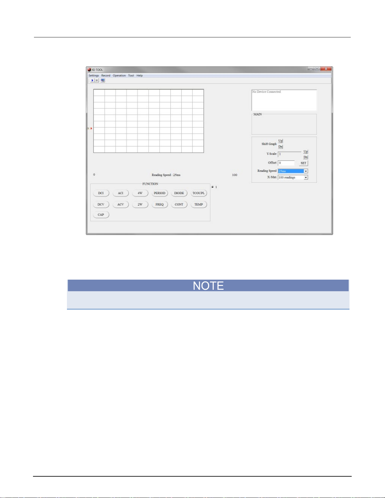
1. Install the USB device driver and KI-Tool software from the Keithley Instruments Model 2110
Product Information CD.
2. Connect the Model 2110 to the USB port and launch the KI-Tool software.
3. Verify that correct model number is displayed in the upper right-hand corner of the tool. See
Figure 1 for details.
4. Test the communications link between the Model 2110 and the control software by clicking
several function buttons and verify that the Model 2110 responds accordingly. See the figure
below for more details.
Page 9
Section
Calibration Manual
1: Calibrating and adjusting the Model 2110 Model 2110 5½ Digit Multimeter
Figure 1: Model 2110 KI-TOOL software
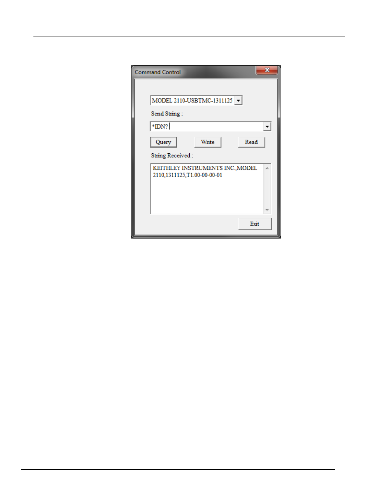
5. The procedure consists of connecting the Fluke 5700A/5725A and 5520A/5522A output to the
Model 2110 front panel input, setting up appropriate ranges, and performing calibration by
sending specific SCPI commands. These commands are entered into the Send String field
followed by clicking the Write button. To access the command control window, click Tool >
Command Control.
The figure below shows the Command Control window. Ensure that the correct model number is
selected before sending any SCPI commands.
1-2 2110-905-01 Rev. C / August 2013
Page 10
Model 2110
odel 2110
5½ Digit Multimeter Calibration Manual Section 1: Calibrating and adjusting the M
Figure 2: Command Control window
Environmental conditions
Perform the calibration procedures in an environment that has:
• An ambient temperature of 18 °C to 28 °C
• A relative humidity of less than 80 percent unless otherwise noted.
Calibration considerations
When performing the calibration procedure:
• Make sure that the equipment is properly warmed up and connected to the appropriate input
jacks.
• Make sure the calibrator is in OPERATE before you complete each calibration step.
• Do not connect test equipment to the Model 2110 through a scanner or other switching
equipment.
• If an error occurs during calibration, the Model 2110 will generate an appropriate error message.
Please refer to The Model 2110 Reference Manual for error code descriptions.
• During the adjustment process, the Model 2110 may not display the correct amplitude of the
applied signal. This condition is normal.
• After the adjustment procedures are completed, perform the performance verification in Section 3
to verify that the Model 2110 is within manufacturer’s specifications.
2110-905-01 Rev. C / August 2013 1-3
Page 11

Section
Calibration Manual
1: Calibrating and adjusting the Model 2110 Model 2110 5½ Digit Multimeter
Recommended test equipment
Use the Fluke 5700A Calibrator and the Fluke 5725A Amplifier (or the equivalent or better) and the
Fluke 5520A/5522A for temperature and capacitance to calibrate the Model 2110.
Calibration code
To unlock and initiate calibration:
1. Unlock calibration by sending the following command:
CAL:PROT:CODE <up to 8-character string>
The default command is:
CAL:PROT:CODE 123456
2. Initiate calibration by sending the following command:
CAL:PROT:INIT
1-4 2110-905-01 Rev. C / August 2013
Page 12

Calibration date ...................................................................... 2-18
In this section:
Voltage function adjustment (DC and AC)................................ 2-1
Ohms function adjustment........................................................ 2-6
Current function adjustment (DC and AC) .............................. 2-12
Temperature function adjustm ent ........................................... 2-16
Capacitance function adjustment ........................................... 2-16
Voltage function adjustment (DC and AC)
The ranges for DC voltage (DCV) adjustment are 100 mV, 1 V, 10 V, 100 V, and 1000 V. For AC
voltage (ACV) adjustment, the ranges are 100 mV, 1 V, 10 V, 100 V, and 750 V RMS at 1 kHz.
Section 2
Adjustment
Do not apply more than 1000 V (peak) to the Model 2110. Applying excess voltage may
damage your Model 2110 and create a shock hazard that could result in injury or death.
To eliminate the thermal EMFs due to the differences between two metals, use copper leads to
connect your source signal to the DMM.
DCV range adjustment
1. Set the Model 5700A for 0 V DC using AUTO RANGE. Set the output to the STANDBY mode.
2. Using shielded, low thermal EMF cables, connect the Fluke 5700A output HI and LO to the Model
2110 input HI and LO terminals. Allow connections to stabilize for a minimum of five minutes
before proceeding.
3. Set the Model 2110 to the 100mV DC voltage range by sending the following command:
CONF:VOLT:DC 0.1
4. Set the Model 5700A output mode to OPERATE.
5. Adjust the input offset by sending the following command:
CAL:PROT:DC:STEP 1,0
6. Wait until the following message is displayed on the Model 2110:
Cali OK
Page 13

Section
Calibration Manual
2: Adjustment Model 2110 5½ Digit Multimeter
7. Set the Model 5700A to output 100mVDC.
8. Adjust for full scale measurement by sending the following command:
CAL:PROT:DC:STEP 2,0.1
9. Wait until the following message is displayed on the Model 2110:
Cali OK
10. Set the 5700A to output -100mVDC.
11. Adjust for full scale measurement by sending the following command:
CAL:PROT:DC:STEP 2,-0.1
12. Wait until the following message is displayed on the Model 2110:
Cali OK
13. Set the Model 5700A output mode to STANDBY.
14. Set the Model 2110 to the 1 V range by sending the following command:
CONF:VOLT:DC 1
15. Set the Model 5700A for 0 V DC and set the output to the OPERATE mode.
16. Adjust the input offset by sending the following command:
CAL:PROT:DC:STEP 1,0
17. Wait until the following message is displayed on the Model 2110:
Cali OK
18. Set the Model 5700A output to 1 V DC.
19. Adjust for full scale measurement by sending the following command:
CAL:PROT:DC:STEP 2,1
20. Wait until the following message is displayed on the Model 2110:
Cali OK
21. Set 5700A output to -1 V DC.
22. Adjust full scale measurement by sending the following command:
CAL:PROT:DC:STEP 2,-1
23. Wait until the following message is displayed on the Model 2110:
Cali OK
24. Set the Model 5700A output mode to STANDBY.
25. Set the Model 2110 to the 10 V range by sending the following command:
CONF:VOLT:DC 10
26. Set the Model 5700A to 0 V DC and the output mode to OPERATE.
27. Adjust input offset by sending the following command:
CAL:PROT:DC:STEP 1,0
28. Wait until the following message is displayed on the Model 2110:
Cali OK
2-2 2110-905-01 Rev. C / August 2013
Page 14

Model 2110
Adjustment
5½ Digit Multimeter Calibration Manual Section 2:
29. Set the Model 5700A output to -10 V DC.
30. Adjust full scale measurement by sending the following command:
CAL:PROT:DC:STEP 2,-10
31. Wait until the following message is displayed on the Model 2110:
Cali OK
32. Set the Model 5700A output mode to STANDBY.
33. Configure the Model 2110 for the 100 V range by sending the following command:
CONF:VOLT:DC 100
34. Set the Model 5700A to 0 V DC and set the output mode to OPERATE.
35. Adjust input offset by sending the following command:
CAL:PROT:DC:STEP 1,0
36. Wait until the following message is displayed on the Model 2110:
Cali OK
37. Set the Model 5700A output to 100 V DC.
38. Adjust full scale measurement by sending the following command:
CAL:PROT:DC:STEP 2,100
39. Wait until the following message is displayed on the Model 2110:
Cali OK
40. Set the Model 5700A output to -100 V DC.
41. Adjust full scale measurement by sending the following command:
CAL:PROT:DC:STEP 2,-100
42. Wait until the following message is displayed on the Model 2110:
Cali OK
43. Set the Model 5700A output mode to STANDBY.
44. Configure the Model 2110 for the 1000 V range by sending the following command:
CONF:VOLT:DC 1000
45. Set the Model 5700A to 0 V DC and set the output mode to OPERATE.
46. Adjust input offset by sending the following command:
CAL:PROT:DC:STEP 1,0
47. Wait until the following message is displayed on the Model 2110:
Cali OK
48. Set the Model 5700A output to 1000 V DC.
49. Adjust full scale measurement by sending the following command:
CAL:PROT:DC:STEP 2,1000
50. Wait until the following message is displayed on the Model 2110:
Cali OK
51. Set the Model 5700A output to -1000 V DC.
52. Adjust full scale measurement by sending the following command:
CAL:PROT:DC:STEP 2,-1000
53. Wait until the following message is displayed on the Model 2110:
Cali OK
54. Set the Model 5700A to 0 V DC and theoutput mode to STANDBY.
2110-905-01 Rev. C / August 2013 2-3
Page 15

Section
Calibration Manual
2: Adjustment Model 2110 5½ Digit Multimeter
ACV range adjustment
1. Set the Model 5700A to 0.01 V at 1 kHz and the output mode to STANDBY.
2. Using coaxial cable with dual banana terminals connect the Fluke 5700A output HI and LO to the
Model 2110 input HI and LO terminals. Allow connections to stabilize for a minimum of five
minutes before proceeding.
3. Configure the Model 2110 for the 0.1 V range by sending the following command:
CONF:VOLT:AC 0.1
4. Set the Model 5700A output mode to OPERATE.
5. Adjust to 10 percent of range by sending the following command:
CAL:PROT:AC:STEP 1,0.01
6. Wait until the following message is displayed on the Model 2110:
Cali OK
7. Set the Model 5700A output to 0.1 V.
8. Adjust full scale measurement by sending the following command:
CAL:PROT:AC:STEP 2,0.1
9. Wait until the following message is displayed on the Model 2110:
Cali OK
10. Set the Model 5700A output mode to STANDBY.
11. Configure the Model 2110 for the 1 V range by sending the following command:
CONF:VOLT:AC 1
12. Set the Model 5700A to 0.1 V and the output mode to OPERATE.
13. Adjust to 10 percent of range by sending the following command:
CAL:PROT:AC:STEP 1,0.1
14. Wait until the following message is displayed on the Model 2110:
Cali OK
15. Set the Model 5700A output to 1 V.
16. Adjust full scale measurement by sending the following command:
CAL:PROT:AC:STEP 2,1
17. Wait until the following message is displayed on the Model 2110:
Cali OK
18. Set the Model 5700A output mode to STANDBY.
19. Configure the Model 2110 for the 10 V range by sending the following command:
CONF:VOLT:AC 10
20. Set the Model 5700A to 1 V and the output mode to OPERATE.
21. Adjust to 10 percent of range by sending the following command:
CAL:PROT:AC:STEP 1,1
22. Wait until the following message is displayed on the Model 2110:
Cali OK
23. Set the Model 5700A output to 10 V.
24. Adjust full scale measurement by sending the following command:
CAL:PROT:AC:STEP 2,10
25. Wait until the following message is displayed on the Model 2110:
Cali OK
2-4 2110-905-01 Rev. C / August 2013
Page 16

Model 2110
Adjustment
5½ Digit Multimeter Calibration Manual Section 2:
26. Set the Model 5700A output mode to STANDBY.
27. Configure the Model 2110 for the 100 V range by sending the following command:
CONF:VOLT:AC 100
28. Set the Model 5700A to 10 V and the output mode to OPERATE.
29. Adjust to 10 percent of range by sending the following command:
CAL:PROT:AC:STEP 1,10
30. Wait until the following message is displayed on the Model 2110:
Cali OK
31. Set the Model 5700A output to 100 V.
32. Adjust full scale measurement by sending the following command:
CAL:PROT:AC:STEP 2,100
33. Wait until the following message is displayed on the Model 2110:
Cali OK
34. Set the Model 5700A output mode to STANDBY.
35. Configure the Model 2110 for the 750 V range by sending the following command:
CONF:VOLT:AC 750
36. Set the Model 5700A to 75 V and the output mode to OPERATE.
37. Adjust to 10 percent of range by sending the following command:
CAL:PROT:AC:STEP 1,75
38. Wait until the following message is displayed on the Model 2110:
Cali OK
39. Set the Model 5700A output to 750 V.
40. Adjust full scale measurement by sending the following command:
CAL:PROT:AC:STEP 2,750
41. Wait until the following message is displayed on the Model 2110:
Cali OK
42. Set the Model 5700A output mode to STANDBY. Press RESET on the Model 5700A front panel
to reset the calibrator to its default settings.
2110-905-01 Rev. C / August 2013 2-5
Frequency range adjust m e nt
1. Set the Model 5520A/5522A to 1 VAC 1 kHz: output to STANDBY mode.
2. Using shielded, low thermal EMF cables, connect the Fluke 5520A/5522A output HI and LO to
the Model 2110 input HI and LO terminals. Allow connections to stabilize for a minimum of five
minutes before proceeding.
3. Configure the Model 2110 for the 1 kHz range by sending the following command:
CONF:FREQ
4. Configure the Model 2110 for 1 V range and an aperture of 1 by sending the following
commands.
FREQ:VOLT:RANGE 1
FREQ:APER 1
Page 17

Section
Calibration Manual
2: Adjustment Model 2110 5½ Digit Multimeter
5. Set the the Model 5520A/5522A to OPERATE.
6. Adjust input offset by sending the following command:
CAL:PROT:AC:STEP 0,1E3
7. Wait until the following message is displayed on the Model 2110:
Cali OK
8. Set the Model 5520A/5522A output mode to STANDBY. Press RESET on the Model
5520A/5522A front panel to reset the calibrator to its default settings.
Ohms function adjustment
Ohms, low range adjustment (100Ω - 10MΩ) 2 wire
1. Set the Model 5700A to 0Ω, 2 WIRE COMP ON, EX SNS off, EX GRD off, and the output mode
to STANDBY.
2. Using shielded, low thermal EMF cables, connect the Fluke 5700A output HI and LO to the Model
2110 input HI and LO terminals. Allow connections to stabilize for a minimum of five minutes
before proceeding.
3. Configure the Model 2110 for 2-wire, 100 Ω resistance measurements by sending the following
command:
CONF:RES 1E2
4. Set the measurement rate to 10 PLC by sending the following command:
RES:NPLC 10
5. Disable the average function by sending the following command:
AVERAGE:STAT OFF
6. Set the Model 5700A output mode to OPERATE.
7. Adjust input offset by sending the following command:
CAL:PROT:DC:STEP 1,0
8. Wait until the following message is displayed on the Model 2110:
Cali OK
9. Set the Model 5700A output to 100 Ω.
10. Adjust full scale measurement by sending the following command:
CAL:PROT:DC:STEP 2,<ACTUAL CALIBRATOR OUTPUT>
Enter actual output value in scientific notation format.
Example: if calibrator’s display shows 99.99615 Ohms, enter this value as:
CAL:PROT:DC:STEP 2,.9999615E2
11. Wait until the following message is displayed on the Model 2110:
Cali OK
12. Set the Model 5700A output mode to STANDBY.
13. Configure the Model 2110 for 2-wire, 1 kΩ resistance measurements by sending the following
command:
2-6 2110-905-01 Rev. C / August 2013
CONF:RES 1E3
Page 18

Model 2110
Adjustment
5½ Digit Multimeter Calibration Manual Section 2:
14. Set the measurement rate to 10 PLC by sending the following command:
RES:NPLC 10
15. Set the Model 5700A output mode to OPERATE.
16. Adjust input offset by sending the following command:
CAL:PROT:DC:STEP 1,0
17. Wait until the following message is displayed on the Model 2110:
Cali OK
18. Set the Model 5700A output to 1 kΩ.
19. Adjust full scale measurement by sending the following command:
CAL:PROT:DC:STEP 2,<ACTUAL CALIBRATOR OUTPUT>
20. Wait until the following message is displayed on the Model 2110:
Cali OK
21. Set the Model 5700A output mode to STANDBY.
22. Configure the Model 2110 for 2-wire, 10 kΩ resistance measurements by sending the following
command:
CONF:RES 1E4
23. Set the measurement rate to 10 PLC by sending the following command:
RES:NPLC 10
24. Set the Model 5700A to 0Ω and the output mode to OPERATE.
25. Adjust input offset by sending the following command:
CAL:PROT:DC:STEP 1,0
26. Wait until the following message is displayed on the Model 2110:
Cali OK
27. Set the Model 5700A output to 10kΩ.
28. Adjust full scale measurement by sending the following command:
CAL:PROT:DC:STEP 2,<ACTUAL CALIBRATOR OUTPUT>
29. Wait until the following message is displayed on the Model 2110:
Cali OK
30. Set the Model 5700A output mode to STANDBY.
31. Configure the Model 2110 for 2-wire, 100 kΩ resistance measurements by sending the following
command:
CONF:RES 1E5
32. Set the measurement rate to 10 PLC by sending the following command:
RES:NPLC 10
33. Set the Model 5700A to 0Ω and the output mode to OPERATE.
34. Adjust input offset by sending the following command:
CAL:PROT:DC:STEP 1,0
35. Wait until the following message is displayed on the Model 2110:
Cali OK
2110-905-01 Rev. C / August 2013 2-7
Page 19

Section
Calibration Manual
2: Adjustment Model 2110 5½ Digit Multimeter
36. Set the Model 5700A output to 100kΩ.
37. Adjust full scale measurement by sending the following command:
CAL:PROT:DC:STEP 2,<ACTUAL CALIBRATOR OUTPUT>
38. Wait until the following message is displayed on the Model 2110:
Cali OK
39. Set the Model 5700A output mode to STANDBY.
40. Configure the Model 2110 for 2-wire, 1MΩ resistance measurements by sending the following
command:
CONF:RES 1E6
41. Set the measurement rate to 10 PLC by sending the following command:
RES:NPLC 10
42. Set the Model 5700A to 0Ω and the output mode to OPERATE.
43. Adjust input offset by sending the following command:
CAL:PROT:DC:STEP 1,0
44. Wait until the following message is displayed on the Model 2110:
Cali OK
45. Set the Model 5700A output to 1 MΩ.
46. Adjust full scale measurement by sending the following command:
CAL:PROT:DC:STEP 2,<ACTUAL CALIBRATOR OUTPUT>
47. Wait until the following message is displayed on the Model 2110:
Cali OK
48. Set the Model 5700A output mode to STANDBY.
49. Configure the Model 2110 for 2-wire, 10 MΩ resistance measurements by sending the following
command:
CONF:RES 1E7
50. Set the measurement rate to 10 PLC by sending the following command:
RES:NPLC 10
51. Set the Model 5700A to 0Ω and the output mode to OPERATE.
52. Adjust input offset by sending the following command:
CAL:PROT:DC:STEP 1,0
53. Wait until the following message is displayed on the Model 2110:
Cali OK
54. Set the Model 5700A output to 10MΩ.
55. Adjust full scale measurement by sending the following command:
CAL:PROT:DC:STEP 2,<ACTUAL CALIBRATOR OUTPUT>
56. Wait until the following message is displayed on the Model 2110:
Cali OK
57. Set the Model 5700A output mode to STANDBY.
2-8 2110-905-01 Rev. C / August 2013
Page 20

Model 2110
Adjustment
5½ Digit Multimeter Calibration Manual Section 2:
Ohms, low range adjustment (100Ω - 10MΩ) 4 wire
1. Set the Model 5700A to 0Ω, EX SNS on, EX GRD off, and the output mode to STANDBY.
2. Using shielded, low thermal EMF cables, connect the Fluke 5700A output HI and LO to the Model
2110 input HI and LO terminals. Allow connections to stabilize for a minimum of five minutes
before proceeding.
3. Configure the Model 2110 for 4-wire, 100 Ω resistance measurements by sending the following
command:
CONF:FRES 1E2
4. Set the measurement rate to 10 PLC by sending the following command:
FRES:NPLC 10
5. Disable the average function by sending the following command:
AVERAGE:STAT OFF
6. Set the Model 5700A output mode to OPERATE.
7. Adjust input offset by sending the following command:
CAL:PROT:DC:STEP 1,0
8. Wait until the following message is displayed on the Model 2110:
Cali OK
9. Set the Model 5700A output to 100Ω.
10. Adjust full scale measurement by sending the following command:
CAL:PROT:DC:STEP 2,<ACTUAL CALIBRATOR OUTPUT>
11. Wait until the following message is displayed on the Model 2110:
Cali OK
12. Set the Model 5700A output mode to STANDBY.
13. Configure the Model 2110 for 4-wire, 1 kΩ resistance measurements by sending the following
command:
CONF:FRES 1E3
14. Set the measurement rate to 10 PLC by sending the following command:
FRES:NPLC 10
15. Set the Model 5700A output mode to OPERATE.
16. Adjust input offset by sending the following command:
CAL:PROT:DC:STEP 1,0
17. Wait until the following message is displayed on the Model 2110:
Cali OK
18. Set the Model 5700A output to 1kΩ.
19. Adjust full scale measurement by sending the following command:
CAL:PROT:DC:STEP 2,<ACTUAL CALIBRATOR OUTPUT>
20. Wait until the following message is displayed on the Model 2110:
Cali OK
2110-905-01 Rev. C / August 2013 2-9
Page 21

Section
ion Manual
2: Adjustment Model 2110 5½ Digit Multimeter Calibrat
21. Set the Model 5700A output mode to STANDBY.
22. Configure the Model 2110 for 4-wire, 10 kΩ resistance measurements by sending the following
command:
CONF:FRES 1E4
23. Set the measurement rate to 10 PLC by sending the following command:
FRES:NPLC 10
24. Set the Model 5700A to 0Ω and the output mode to OPERATE.
25. Adjust input offset by sending the following command:
CAL:PROT:DC:STEP 1,0
26. Wait until the following message is displayed on the Model 2110:
Cali OK
27. Set the Model 5700A output to 10kΩ.
28. Adjust full scale measurement by sending the following command:
CAL:PROT:DC:STEP 2,<ACTUAL CALIBRATOR OUTPUT>
29. Wait until the following message is displayed on the Model 2110:
Cali OK
30. Set the Model 5700A output mode to STANDBY.
31. Configure the Model 2110 for 4-wire, 100 kΩ resistance measurements by sending the following
command:
CONF:FRES 1E5
32. Set the measurement rate to 10 PLC by sending the following command:
FRES:NPLC 10
33. Set the Model 5700A to 0Ω and the output mode to OPERATE.
34. Adjust input offset by sending the following command:
CAL:PROT:DC:STEP 1,0
35. Wait until the following message is displayed on the Model 2110:
Cali OK
36. Set the Model 5700A output to 100kΩ.
37. Adjust full scale measurement by sending the following command:
CAL:PROT:DC:STEP 2,<ACTUAL CALIBRATOR OUTPUT>
38. Wait until the following message is displayed on the Model 2110:
Cali OK
39. Set the Model 5700A output mode to STANDBY.
40. Configure the Model 2110 for 4-wire, 1 MΩ resistance measurements by sending the following
command:
CONF:FRES 1E6
41. Set the measurement rate to 10 PLC by sending the following command:
FRES:NPLC 10
42. Set the Model 5700A to 0Ω and the output mode to OPERATE.
43. Adjust input offset by sending the following command:
CAL:PROT:DC:STEP 1,0
44. Wait until the following message is displayed on the Model 2110:
Cali OK
2-10 2110-905-01 Rev. C / August 2013
Page 22

Model 2110
Adjustment
5½ Digit Multimeter Calibration Manual Section 2:
45. Set the Model 5700A output to 1MΩ.
46. Adjust full scale measurement by sending the following command:
CAL:PROT:DC:STEP 2,<ACTUAL CALIBRATOR OUTPUT>
47. Wait until the following message is displayed on the Model 2110:
Cali OK
48. Set the Model 5700A output mode to STANDBY.
49. Configure the Model 2110 for 4-wire, 10 MΩ resistance measurements by sending the following
command:
CONF:FRES 1E7
50. Set the measurement rate to 10 PLC by sending the following command:
FRES:NPLC 10
51. Set the Model 5700A to 0 Ω and the output mode to OPERATE.
52. Adjust input offset by sending the following command:
CAL:PROT:DC:STEP 1,0
53. Wait until the following message is displayed on the Model 2110:
Cali OK
54. Set the Model 5700A output to 10 MΩ.
55. Adjust full scale measurement by sending the following command:
CAL:PROT:DC:STEP 2,<ACTUAL CALIBRATOR OUTPUT>
56. Wait until the following message is displayed on the Model 2110:
Cali OK
57. Set the Model 5700A output mode to STANDBY.
Ohms, high range adjustment (100 MΩ)
1. Set the Model 5700A to 0 Ω, 2 WIRE COMP OFF, EX SNS off, EX GRD off, and the output mode
to STANDBY.
2. Using shielded, low thermal EMF cables, connect the Fluke 5700A output HI, output LO, sense
HI, and sense LO terminals to the Model 2110 input HI, input LO, sense HI, and sense LO
terminals. Allow connections to stabilize for a minimum of five minutes before proceeding.
3. Configure the Model 2110 for 2-wire, 100 MΩ resistance measurements by sending the following
command:
CONF:RES 1E8
4. Set the measurement rate to 10 PLC by sending the following command:
RES:NPLC 10
5. Set the Model 5700A output to 10 MΩ
6. Set the Model 5700A output mode to OPERATE.
7. Adjust to 10 percent of scale by sending the following command:
CAL:PROT:DC:STEP 1,<ACTUAL CALIBRATOR OUTPUT>
8. Wait until the following message is displayed on the Model 2110:
Cali OK
2110-905-01 Rev. C / August 2013 2-11
Page 23

Section
al
2: Adjustment Model 2110 5½ Digit Multimeter Calibration Manu
9. Set the Model 5700A output to 100 MΩ.
10. Adjust full scale measurement by sending the following command:
CAL:PROT:DC:STEP 2,<ACTUAL CALIBRATOR OUTPUT>
11. Wait until the following message is displayed on the Model 2110:
Cali OK
12. Set the Model 5700A output mode to STANDBY.
Current function adjustment (DC and AC)
DC current range adjustment
1. Set the Model 5700A to 0A, CURRNT OUTPUT: 5725, RANGE: AUTO, and the output mode to
STANDBY.
2. Using shielded, low thermal EMF cables, connect the Fluke 5725A current output HI and output
LO to the Model 2110 input AMPS and input LO terminals. Allow connections to stabilize for a
minimum of five minutes before proceeding.
3. Configure the Model 2110 to 0.1A DC current range by sending the following command:
CONF:CURR:DC 0.1
4. Set the measurement rate to 10 PLC by sending the following command:
CURR:NPLC 10
5. Set the Model 5700A output mode to OPERATE.
6. Adjust front input offset by sending the following command:
CAL:PROT:DC:STEP 1,0
7. Wait until the following message is displayed on the Model 2110:
Cali OK
8. Set the Model 5700A output to 0.1A DC.
9. Adjust full scale measurement by sending the following command:
CAL:PROT:DC:STEP 2,0.1
10. Wait until the following message is displayed on the Model 2110:
Cali OK
11. Set the Model 5700A output mode to STANDBY.
12. Set the Model 5700A output to -0.1A DC.
13. Adjust full scale measurement by sending the following command:
CAL:PROT:DC:STEP 2,-0.1
14. Wait until the following message is displayed on the Model 2110:
Cali OK
15. Set the Model 5700A output mode to STANDBY.
16. Configure the Model 2110 to 1A DC current range by sending the following command:
CONF:CURR:DC 1
17. Set the measurement rate to 10 PLC by sending the following command:
CURR:NPLC 10
18. Set the Model 5700A to 0A and the output mode to OPERATE.
19. Adjust front input offset by sending the following command:
CAL:PROT:DC:STEP 1,0
2-12 2110-905-01 Rev. C / August 2013
Page 24

Model 2110
Adjustment
5½ Digit Multimeter Calibration Manual Section 2:
20. Wait until the following message is displayed on the Model 2110:
Cali OK
21. Set the Model 5700A output to 1A DC.
22. Adjust full scale measurement by sending the following command:
CAL:PROT:DC:STEP 2,1
23. Wait until the following message is displayed on the Model 2110:
Cali OK
24. Set the Model 5700A output mode to STANDBY. .
25. Set the Model 5700A output to -1A DC.
26. Adjust full scale measurement by sending the following command:
CAL:PROT:DC:STEP 2,-1
27. Wait until the following message is displayed on the Model 2110:
Cali OK
28. Set the Model 5700A output mode to STANDBY.
DC high current adjustment
1. Connect the Model 2110 3 A input jack to the 5725A 11A output (white to red on the Model 5725
and black of the Model 2110 to black of the Model 5725. Configure the Model 5700 to output
current to the Model 5725A.
2. Configure the Model 2110 for the 3 A DC current range by sending the following command:
CONF:CURR:DC 3
3. Set the measurement rate to 10 PLC by sending the following command:
CURR:NPLC 10
4. Set the Model 5700A to 0 A and the output mode to OPERATE.
5. Adjust front input offset by sending the following command:
CAL:PROT:DC:STEP 1,0
6. Wait until the following message is displayed on the Model 2110:
Cali OK
7. Set the Model 5700A output to 3 A DC.
8. Adjust full scale measurement by sending the following command:
CAL:PROT:DC:STEP 2,3
9. Wait until the following message is displayed on the Model 2110:
Cali OK
10. Set the Model 5700A output mode to STANDBY.
11. Set the Model 5700A output to -3 A DC.
12. Adjust full scale measurement by sending the following command:
CAL:PROT:DC:STEP 2,-3
13. Wait until the following message is displayed on the Model 2110:
Cali OK
2110-905-01 Rev. C / August 2013 2-13
Page 25

Section
Calibration Manual
2: Adjustment Model 2110 5½ Digit Multimeter
14. Set the Model 5700A output mode to STANDBY.
15. Configure the Model 2110 for the 10 A DC current range by sending the following command:
CONF:CURR:DC 10
16. Set the measurement rate to 10 PLC by sending the following command:
CURR:NPLC 10
17. Set the Model 5700A to 0 A and the output mode to OPERATE.
18. Adjust front input offset by sending the following command:
CAL:PROT:DC:STEP 1,0
19. Wait until the following message is displayed on the Model 2110:
Cali OK
20. Set the Model 5700A output to 3 A DC.
21. Adjust full scale measurement by sending the following command:
CAL:PROT:DC:STEP 2,10
22. Wait until the following message is displayed on the Model 2110:
Cali OK
23. Set the Model 5700A output mode to STANDBY. .
24. Set the Model 5700A output to -3 A DC.
25. Adjust full scale measurement by sending the following command:
CAL:PROT:DC:STEP 2,-10
26. Wait until the following message is displayed on the Model 2110:
Cali OK
27. Set the Model 5700A output mode to STANDBY. Press RESET on the Model 5700A front panel
to reset the calibrator to its default settings.
AC current range adjustment
1. Set the Model 5700A to 0.1 A at 1 kHz, CURRENT OUTPUT: 5725, and the output mode to
STANDBY.
2. Using coaxial cable with dual banana terminals, connect the Fluke 5725A current output HI and
LO to the Model 2110 input AMPS and LO terminals. Allow connections to stabilize for a
minimum of five minutes before proceeding.
3. Configure the Model 2110 for the 1A AC current range by sending the following command:
CONF:CURR:AC 1
4. Set the Model 5700A output mode to OPERATE.
5. Adjust to 10 percent of range by sending the following command:
CAL:PROT:AC:STEP 1,0.1
6. Wait until the following message is displayed on the Model 2110:
Cali OK
7. Set the Model 5700A output to 1 A at 1 kHZ.
8. Adjust full scale range by sending the following command:
CAL:PROT:AC:STEP 2,1
9. Wait until the following message is displayed on the Model 2110:
Cali OK
10. Set the Model 5700A output mode to STANDBY.
2-14 2110-905-01 Rev. C / August 2013
Page 26

Model 2110
Adjustment
5½ Digit Multimeter Calibration Manual Section 2:
AC high current adjustment
1. Connect the Model 2110 3 A input jack to the 5725A 11A output (white to red on the Model
5725A and black of the Model 2110 to black of the Model 5725A). Configure the Model 5700 to
output current to the Model 5725A.
2. Configure the Model 2110 for the 3 A, 1 kHz current range by sending the following command:
CONF:CURR:AC 3
3. Set the Model 5700A to 0 A and the output mode to OPERATE.
4. Adjust front input offset by sending the following command:
CAL:PROT:AC:STEP 1,0
5. Wait until the following message is displayed on the Model 2110:
Cali OK
6. Set the Model 5700A output to 300 mA 1 kHz.
7. Adjust full scale measurement by sending the following command:
CAL:PROT:AC:STEP 2,0.3
8. Wait until the following message is displayed on the Model 2110:
Cali OK
9. Set the Model 5700A output mode to STANDBY. .
10. Set the Model 5700A output to 3 A, 1 kHz.
11. Adjust full scale measurement by sending the following command:
CAL:PROT:AC:STEP 2,3
12. Wait until the following message is displayed on the Model 2110:
Cali OK
13. Set the Model 5700A output mode to STANDBY.
14. Configure the Model 2110 for the 10 A DC current range by sending the following command:
CONF:CURR:AC 10
15. Set the Model 5700A to 1 A, 1 kHz and set the output mode to OPERATE.
16. Adjust front input offset by sending the following command:
CAL:PROT:AC:STEP 1,1
17. Wait until the following message is displayed on the Model 2110:
Cali OK
18. Set the Model 5700A output to 10 A, 1 kHz.
19. Adjust full scale measurement by sending the following command:
CAL:PROT:AC:STEP 2,10
20. Wait until the following message is displayed on the Model 2110:
Cali OK
2110-905-01 Rev. C / August 2013 2-15
Page 27

Section
Calibration Manual
2: Adjustment Model 2110 5½ Digit Multimeter
Temperature function adjustment
1. Set the Model 5520A/5522A to 0 Deg C, and the output mode to STANDBY.
2. Using Type K thermocouple wire with TC jacks on both ends, connect the Fluke 5520A/5522A TC
output to the Model 2110 input TC terminals. Allow connections to stabilize for a minimum of five
minutes before proceeding.
3. Configure the Model 2110 for the type K by sending the following command:
CONF:TCOUPLE
4. Set the Model 5520A/5522A output to 0 Deg C, type K Thermocouple, and the output mode to
OPERATE.
5. Adjust the upper region of the range by sending the following command:
CAL:PROT:DC:STEP 1,0
6. Wait until the following message is displayed on the Model 2110:
CALI OK
7. Set the Model 5520A/5522A output mode to STANDBY. Press RESET on the Model
5520A/5522A front panel to reset the calibrator to its default settings.
Capacitance function adjustment
1. Set the Model 5520A/55 22 A to 1 µF range and the output mode to STANDBY.
2. Using shielded, low thermal EMF cables, connect the Fluke 5700A output HI and LO to the Model
2110 input HI and LO terminals. Allow connections to stabilize for a minimum of five minutes
before proceeding.
3. Configure the Model 2110 for the 1 µF capacitance range by sending the following command:
CONF:CAP 1E-6
4. Set the Model 5520A/5522A output mode to STANDBY.
5. Adjust input offset by sending the following command:
CAL:PROT:DC:STEP 1,0
6. Wait until the following message is displayed on the Model 2110:
Cali OK
7. Set the Model 5520A/5522A output to 1UF.
8. Adjust full scale measurement by sending the following command:
CAL:PROT:DC:STEP 2,1E-6
9. Wait until the following message is displayed on the Model 2110:
Cali OK
10. Configure the Model 2110 for the 10 µF Capacitance range by sending the following command:
CONF:CAP 1E-5
11. Set the Model 5520A/5522A output mode to STANDBY.
12. Adjust input offset by sending the following command:
CAL:PROT:DC:STEP 1,0
13. Wait until the following message is displayed on the Model 2110:
Cali OK
2-16 2110-905-01 Rev. C / August 2013
Page 28

Model 2110
Adjustment
5½ Digit Multimeter Calibration Manual Section 2:
14. Set the Model 5520A/5522A output to 10UF.
15. Adjust full scale measurement by sending the following command:
CAL:PROT:DC:STEP 2,1E-5
16. Wait until the following message is displayed on the Model 2110:
Cali OK
17. Configure the Model 2110 for the 100 µF capacitance range by sending the following command:
CONF:CAP 1E-4
18. Set the Model 5520A/5522A output mode to STANDBY.
19. Adjust input offset by sending the following command:
CAL:PROT:DC:STEP 1,0
20. Wait until the following message is displayed on the Model 2110:
Cali OK
21. Set the Model 5520A/5522A output to 100 µF.
22. Adjust full scale measurement by sending the following command:
CAL:PROT:DC:STEP 2,1E-4
23. Wait until the following message is displayed on the Model 2110:
Cali OK
24. Configure the Model 2110 for the 1 mF capacitance range by sending the following command:
CONF:CAP 1E-3
25. Set the Model 5520A/5522A output mode to STANDBY.
26. Adjust the input offset by sending the following command:
CAL:PROT:DC:STEP 1,0
27. Wait until the following message is displayed on the Model 2110:
Cali OK
28. Set the Model 5520A/5522A output to 1 mF.
29. Adjust the full-scale measurement by sending the following command:
CAL:PROT:DC:STEP 2,1E-3
30. Wait until the following message is displayed on the Model 2110:
Cali OK
31. Configure the Model 2110 for the 10 mF Capacitance range by sending the following command:
CONF:CAP 1E-2
32. Set the Model 5520A/5522A output mode to STANDBY.
33. Adjust the input offset by sending the following command:
CAL:PROT:DC:STEP 1,0
34. Wait until the following message is displayed on the Model 2110:
Cali OK
35. Set the Model 5520A/5522A output to 10 mF.
36. Adjust full scale measurement by sending the following command:
CAL:PROT:DC:STEP 2,1E-2
37. Wait until the following message is displayed on the Model 2110:
Cali OK
2110-905-01 Rev. C / August 2013 2-17
Page 29

Section
Calibration Manual
2: Adjustment Model 2110 5½ Digit Multimeter
Calibration date
1. Update the calibration date by sending the following command:
CAL:PROT:DATE <”MM/DD/YYYY”>
The date <string> must be enclosed in double quotes (“<string>”).
Example: If calibration date is 5 Apr 2012, send the following command:
CAL:PROT:DATE ”04/05/2012”
Calibration due date is automatically calculated for 12 months.
2. Save calibration constants in EEPROM by sending the following command:
CAL:PROT:SAVE
3. Lock calibration by sending the following command:
CAL:PROT:LOCK
2-18 2110-905-01 Rev. C / August 2013
Page 30

Performing accuracy verificati on .............................................. 3-1
100 mV
50.0000 mV
50.010 mV
49.990 mV
90.0000 mV
90.015 mV
89.985 mV
10 V
5.0000 V
5.0008 V
4.9992 V
9.0000 V
9.0013 V
8.9987 V
100 V
50.000 V
50.008 V
49.992 V
90.000 V
90.013 V
89.987 V
1000 V
500.00 V
500.09 V
499.91 V
e. Repeat the checks above for negative polarity.
In this section:
Performing accuracy verification
After calibration is completed, the Model 2110 should be verified to ensure that its performance is
within the manufacturer’s specifications.
Perform accuracy verifications using the Fluke 5700A/5725A and 5520A/5522A standards. Refer to
the following tables for accuracy limits for the specified ranges.
Section 3
Performance verifi cati on
DC voltage accuracy verification
DC VOLTAGE ACCURACY VERIFICATION
Range Test Point Accuracy Limits
Upper Limit Lower Limit
1 V 0.500000 V 0.50001 V 0.49992 V
0.900000 V 0.90001 V 0.89988 V
900.00 V 900.14 V -899.86 V
Specifications valid after 2-hour warm-up:
a. ADC set for continuous trigger operation.
b. Input bias current < 30 pA at 25 °C.
c. Input protection 1000 V all ranges (2-W input).
d. Measurement rate set to 1 PLC.
Page 31

Section
Calibration Manual
100.0000 mV @ 75 kHz
100.730 mV
99.270 mV
100.0000 mV @ 300 kHz
105.000 mV
95.000 mV
1 V
1.000000 V @ 10 Hz
1.002 V
0.998 V
1.000000 V @ 30 kHz
1.003 V
0.998 V
1.000000 V @ 75k Hz
1.007 V
0.993 V
1.000000 V @ 300 kHz
1.050 V
0.950 V
10.00000 V @ 75 kHz
10.07 V
9.93 V
10.00000 V @ 300 kHz
10.50 V
9.50 V
100 V
100.0000 V @ 10 Hz
100.17 V
99.83 V
100.0000 V @ 30 kHz
100.30 V
99.70 V
100.0000 V @ 75 kHz
100.73 V
99.27 V
750 V
700.000 V @ 40 Hz
701.22 V
698.79 V
700.00 V @ 30 kHz
702.13 V
697.88 V
700.00 V @ 75 kHz
705.15 V
694.85 V
700.00 V @ 100 kHz
735.25 V
664.75 V
c. 750 V range limited to 100 kHz.
3: Performance verification Model 2110 5½ Digit Multimeter
AC voltage accuracy verification
AC V OLTAGE ACCURACY V ERI FICATION
Range Test Point Accuracy Limits
Upper Limit Lower Limit
100 mV 100.0000 mV @ 10 Hz 100.170 mV 99.830 mV
100.0000 mV @ 30 kHz 100.300 mV 99.700 mV
10 V 10.00000 V @ 10 Hz 10.02 V 9.98 V
10.00000 V @ 30 kHz 10.03 V 9.97 V
100.0000 V @ 200 kHz 105.00 V 95.00 V
Specifications valid for 2-hour warm-up at 5-1/2 digits:
a. Slow ac filter (3 Hz bandwidth).
b. Pure sine wave input greater than 5% of range.
3-2 2110-905-01 Rev. C / August 2013
Page 32

Model 2110
Performance verification
1 kΩ
1.000000 kΩ
1.00022 kΩ
0.99978 kΩ
10 kΩ
10.00000 kΩ
10.0022 kΩ
9.9978 kΩ
100 kΩ
100.0000 kΩ
100.022 kΩ
99.978 kΩ
1 MΩ
1.000000 MΩ
1.00024 MΩ
0.99976 MΩ
10 MΩ
10.00000 MΩ
10.0104 MΩ
9.9896 MΩ
100 MΩ
100.0000 MΩ
101.505 MΩ
98.495 MΩ
Add 1 kΩ per lead for all other ranges.
10 mA
5.0000 mA
5.0045 mA
4.9955 mA
9.0000 mA
9.0065 mA
8.9935 mA
100 mA
50.000 mA
50.035 mA
49.965 mA
0.90000 A
0.90155 A
0.89845 A
3 A
1.50000 A
1.50390 A
1.49610 A
2.70000 A
2.70630 A
2.69370 A
10 A
5.0000 A
5.0175 A
4.9825 A
9.0000 A
9.0275 A
8.9725 A
5½ Digit Multimeter Calibration Manual Section 3:
Resistance accuracy verification
RESISTANCE ACCURACY VERIFICATION
Range Test Point Accuracy Limits
Upper Limit Lower Limit
100 Ω 100.0000 Ω 100.025 Ω 99.9755 Ω
Specifications for 4-W ohms mode:
a. (For 2-W ohms, use zero null or subtract lead resistance from displayed reading.)
b. Max lead resistance 10% of range per lead for 100 Ω and 1 kΩ ranges;
DC current accuracy verification
DC CURRENT ACCURACY VERIFICATION
Range Test Point Accuracy Limits
Upper Limit Lower Limit
90.000 mA 90.055 mA 89.945 mA
1 A 0.50000 A 0.50095 A 0.49905 A
Specifications valid after 2-hour warm-up:
a. ADC set for continuous trigger operation.
b. Input bias current < 30 pA at 25 °C.
c. Input protection 1000 V all ranges (2-W input).
e. Repeat the checks above for negative polarity.
2110-905-01 Rev. C / August 2013 3-3
Page 33

Section
Calibration Manual
1 A
0.90000 A @ 60 Hz
0.90220 A
0.89780 A
0.90000 A @ 5 kHz
0.90220 A
0.89780 A
3 A
2.70000 A @ 60 Hz
2.7099 A
2.6901 A
2.70000 A @ 5 kHz
2.7099 A
2.6901 A
10 A
9.0000 A @ 60 Hz
9.0570 A
8.9430 A
9.0000 A @ 5 kHz
9.0570 A
8.9430 A
10-40 Hz
20.0000 Hz @ 1 Vpp
20.006 Hz
19.994 Hz
40-300 kHz
200.000 kHz @ 1 Vpp
200.04 kHz
199.96 kHz
b. Pure sine wave input greater than 5% of range.
3: Performance verification Model 2110 5½ Digit Multimeter
AC current accuracy verification
AC CURRENT ACCURACY VERIFICATION
Range Test Point Accuracy Limits
Upper Limit Lower Limit
Specifications valid for 2-hour warm-up at 5-1/2 digits:
a. Slow ac filter (3 Hz bandwidth).
b. Pure sine wave input greater than 5% or range.
Frequency accuracy verification
FREQUENCY ACCURACY VERIFICATION
Range Test Point Accuracy Limits
Upper Limit Lower Limit
Specifications valid for 2-hour warm-up at 5-1/2 digits:
a. Slow ac filter (3 Hz bandwidth).
3-4 2110-905-01 Rev. C / August 2013
Page 34

Mod
Performance verification
0.000 °C
1.000 °C
-1.000 °C
-100.000 °C
99.000 °C
-101.000 °C
d. Measurement rate set to 10 PLC (fixed).
1 nF
1.00000 nF
1.02800 nF
0.97200 nF
10 nF
10.0000 nF
10.1500 nF
9.8500 nF
100 nF
100.000 nF
101.500 nF
98.500 nF
10 µF
10.0000 µF
10.1500 µF
9.8500 µF
100 µF
100.000 µF
101.500 µF
98.500 µF
1 mF
1.00000 mF
1.01500 mF
0.98500 mF
10 mF
10.0000 mF
10.2500 mF
9.7500 mF
c. Input protection 1000 V all ranges and 1 mA (10 µF to 10 mF)
el 2110 5½ Digit Multimeter Calibration Manual Section 3:
Temperature accuracy verification
TEMPERATURE ACCURACY VERIFIC ATION
Range Test Point Accuracy Limits
Upper Limit Lower Limit
TC Type K 100.000 °C 101.000 °C 99.000 °C
Specifications valid after 2-hour warm-up at 5-1/2 digits:
a. ADC set for continuous trigger operation.
b. Input bias current < 30 pA at 25 °C.
c. Input protection 1000 V.
Capacitance accuracy verification
CAPACITANCE ACCURACY VERIFICATI ON
Range Test Point Accuracy Limits
Upper Limit Lower Limit
1 µF 1.00000 µF 1.01500 µF 0.98500 µF
Specifications valid after 2-hour warm-up at 5-1/2 digits:
a. ADC set for continuous trigger operation.
b. Input test current: 10 uA (1 nF to 10 nF), 100 µA (100 nF to 10 µF),
and 1 mA (10 µF to 100 µF).
2110-905-01 Rev. C / August 2013 3-5
Page 35

All Keithley trademarks and trade names are the property of Keithley Instruments, Inc.
All other trademarks and trade names are the property of their respective companies.
Specifications are subject to change without notice.
Corporate Headquarters • 28775 Aurora Road • Cleveland, Ohio 44139 • 440-248-0400 • Fax: 440-248-6168 • 1-888-KEITHLEY • www.keithley.com
A Tektronix Company
Keithley Instruments, Inc.
A Greater Measure of Confidence
7/13
 Loading...