

Page 1

www.keithley.com
Model 2100 6 1/2-Digit Resolution Digital Multimeter
Calibration Manual
2100-905-01 Rev. A / April 2008
A GREATER MEASURE OF CONFIDENCE
Page 2

Page 3

WARRANTY
Keithley Instruments, Inc. warrants this product to be free from defects in material and workmanship for a period of
one (1) year from date of shipment.
Keithley Instruments, Inc. warrants the following items for 90 days from the date of shipment: probes, cables,
software, rechargeable batteries, diskettes, and documentation.
During the warranty period, Keithley Instruments will, at its option, either repair or replace any product that proves
to be defective.
To exercise this warranty, write or call your local Keithley Instruments representative, or contact
Keithley Instruments headquarters in Cleveland, Ohio. You will be given prompt assistance and return instructions.
Send the product, transportation prepaid, to the indicated service facility. Repairs will be made and the product
returned, transportation prepaid. Repaired or replaced products are warranted for the balance of the original
warranty period, or at least 90 days.
LIMITATION OF WARRANTY
This warranty does not apply to defects resulting from product modification without Keithley Instruments’ express
written consent, or misuse of any product or part. This warranty also does not apply to fuses, software,
non-rechargeable batteries, damage from battery leakage, or problems arising from normal wear or failure to follow
instructions.
THIS WARRANTY IS IN LIEU OF ALL OTHER WARRANTIES, EXPRESSED OR IMPLIED, INCLUDING ANY
IMPLIED WARRANTY OF MERCHANTABILITY OR FITNESS FOR A PARTICULAR USE. THE REMEDIES
PROVIDED HEREIN ARE BUYER’S SOLE AND EXCLUSIVE REMEDIES.
NEITHER KEITHLEY INSTRUMENTS, INC. NOR ANY OF ITS EMPLOYEES SHALL BE LIABLE FOR ANY
DIRECT, INDIRECT, SPECIAL, INCIDENTAL, OR CONSEQUENTIAL DAMAGES ARISING OUT OF THE USE
OF ITS INSTRUMENTS AND SOFTWARE, EVEN IF KEITHLEY INSTRUMENTS, INC. HAS BEEN ADVISED IN
ADVANCE OF THE POSSIBILITY OF SUCH DAMAGES. SUCH EXCLUDED DAMAGES SHALL INCLUDE, BUT
ARE NOT LIMITED TO: COST OF REMOVAL AND INSTALLATION, LOSSES SUSTAINED AS THE RESULT OF
INJURY TO ANY PERSON, OR DAMAGE TO PROPERTY.
A G R E A T E R M E A S U R E O F C O N F I D E N C E
Keithley Instruments, Inc.
Corporate Headquarters • 28775 Aurora Road • Cleveland, Ohio 44139
440-248-0400 • Fax: 440-248-6168 • 1-888-KEITHLEY (1-888-534-8453) • www.keithley.com
3/07
Page 4

Page 5

The following safety precautions should be observed before using this product and any associated instrumentation. Although some
instruments an d accessorie s would n ormally be used with non-h azardous voltag es, there are situ ations where h azardous conditions ma y
be present.
This product is inte nded for us e by qualifi ed person nel who recognize s hock haz ards and are f amiliar w ith the safe ty precau tions requ ired
to avoid possible in jury. Read and follow all inst alla tion, op era tion, an d mai ntenance i nforma tio n carefu lly b efore us ing the product. Refer
to the user documentation for complete product specifications.
If the product is used in a manner not specified, the protection provided by the product warranty may be impaired.
The types of product users are:
Responsible body is the individual or group responsible for the use and maintenance of equipment, for ensuring that the equipment is
operated within its specifications and operating limits, and for ensuring that operators are adequately trained.
Operators use the product for its inten ded function. T hey must be trained in ele ctrical safety procedures a nd proper us e of the inst rument.
They must be protected from electric shock and contact with hazardous live circuits.
Maintenance personnel perform routine procedures on the product to keep it op era tin g p r op erly, for example, settin g the li ne v oltage or
replacing consuma ble ma terials . Main tenanc e proc edures are descri bed in t he u ser docum ent ation. The proced ures expl icitly st ate if th e
operator may perform them. Otherwise, they should be performed only by service personnel.
Safety Precautions
Service personnel are trained to work on live circ uits, perform safe installa tions, and repair products. Only proper ly trained service
personnel may perform installation and service procedures.
Keithley Instruments products are designed for use with electrical signals that are rated Measurement Category I and Measurement
Category II, as described in the International Electrotechnical Commission (IEC) Standard IEC 60664. Most measurement, control, and
data I/O signals are Measurement Ca tegory I and must not be dire ctly connected to ma ins voltage or to vo ltage sources wi th high transient
over-voltages. Measurement Category II connections require prote ction for high transient over-voltages often as sociated with local AC
mains connect ions. Assume all measurement, co ntrol, and dat a I/O connec tions are for c onnection to Cate gory I sources unless otherwise
marked or described in the user documentation.
Exercise extreme caution when a shock hazard is present. Lethal voltage may be present on cable connector jacks or test fixtures. The
American National Standards Institute (ANSI) states that a shock hazard exists when voltage levels greater than 30V RMS, 42.4V peak,
or 60VDC are present. A good safety practice is to expect that hazardous voltage is present in any unknown circuit before measuring.
Operators of this product must be protected from electric shock at all times. The responsible body must ensure that operators are
prevented acces s and/or insul ated from ev ery connect ion point . In some c ases, conne ctions mus t be expos ed to potenti al human c ontact.
Product operators in th ese ci rcu ms t ances must be train ed t o protect themselves from th e risk of electric shock. If the circuit is capable of
operating at or above 1000V, no conductive part of the circuit may be exposed.
Do not connect switc hing cards direc tly to unlimite d power circui ts. They ar e intended to b e used with im pedance-limite d sources. NEVER
connect switching cards directly to AC mains. When connecting sources to switching cards, install protective devices to limit fault current
and voltage to the card.
Before operating an instrument, ensure that the line cord is connected to a properly-grounded power receptacle. Inspect the connecting
cables, test leads, and jumpers for possible wear, cracks, or breaks before each use.
11/07
Page 6

When install ing equipment where access to the main power cord is r estricted, such as rack mo unting, a separate main in put power
!
disconnect device must be provided in close proximity to the equipment and within easy reach of the operator.
For maximum safety, do not touch the product, test cables, or any other instruments while power is applied to the circuit under test.
AL W AYS remove power from the entire test system and d ischarge an y capaci tors before: c onnecting or disconnect ing cables or jumpers,
installing or removing switching cards, or making internal changes, such as installing or removing jumpers.
Do not touch any o bject that could pro vide a curren t p ath to the com mon sid e of the circ uit under t est or p ower line (e arth) ground . Always
make measurements with dry hands while standing on a dry, insulated surface capable of withstanding the voltage being measured.
The instrument and accessories must be used in accordance with its specifications and operating instructions, or the safety of the
equipment may be impaired.
Do not exceed the maxi mum s ignal levels of the ins trume nts and a ccesso ries, as define d in the sp ecifi cation s and op erat ing info rmation,
and as shown on the instrument or test fixture panels, or switching card.
When fuses are used in a product, replace with the same type and rating for continued protection against fire hazard.
Chassis connections must only be used as shield connections for measuring circuits, NOT as safety earth ground connections.
If you are using a test fixture, keep the lid closed while power is applied to the device under test. Safe operation requires the use of a lid
interlock.
If a screw is present, connect it to safety earth ground using the wire recommended in the user documentation.
The symbol on an instrument indicates that the user should refer to the operating instructions located in the user documentation.
The symbol on an instrument shows that it can source or measure 1000V or more, including the combined effect of normal and
common mode voltages. Use standard safety precautions to avoid personal contact with these voltages.
The symbol on an instrument shows that the surface may be hot. Avoid personal contact to prevent burns.
The symbol indicates a connection terminal to the equipment frame.
If this symbol is on a product, it indicates that mercury is present in the display lamp. Please note that the lamp must be properly
disposed of according to federal, state, and local laws.
The WARNING heading in the user documentation explains dangers that might result in personal injury or death. Always read the
associated information very carefully before performing the indicated procedure.
The CAUTION heading in th e u se r do cu me ntation explains hazards that could damage the instrum ent . Su ch damage may inval ida te the
warranty.
Instrumentation and accessories shall not be connected to humans.
Before performing any maintenance, disconnect the line cord and all test cables.
T o main tain protecti on from electric sho ck and fire, replacem ent component s in mains circu its - includi ng the power transform er, tes t leads,
and input jacks - must be purchased from Keithley Instruments. Standard fuses with applicable national safety approvals may be used if
the rating and type are the same. Other components that are not safety-related may be purchased from other suppliers as long as they
are equivalent to the original component (note that selected parts should be purchased only through Keithley Instruments to maintain
accuracy and function ality of the product). If you ar e unsure about the applicabi lity of a replacement co mponent, call a Keithley Ins truments
office for information.
To clean an instrument, use a damp cloth or mild, water-based cleaner. Clean the exterior of the instrument only. Do not apply cleaner
directly to the instrumen t or allow liqui ds to enter or spi ll on the inst rument. Produ cts tha t consist of a circ uit board with no case or chassis
(e.g., a data acquisition board for installation into a computer) should never require cleaning if handled according to instructions. If the
board becomes contaminated and operation is affected, the board should be returned to the factory for proper cleaning/servicing.
Page 7

Table of Contents
Introduction............................................................................................... 2
Control Software ..................................................................................... 2
Environmental conditions..................................................................... 3
Calibration considerations ................................................................... 3
Recommended test equipment .......................................................... 3
Firmware revision ................................................................................... 4
Calibration code ...................................................................................... 5
Zero calibration (Front/Rear)............................................................... 5
Voltage function adjustment (DC and AC)...................................... 6
Ohms function adjustment................................................................. 12
Current function adjustment (DC and AC).................................... 18
Calibration date..................................................................................... 22
Performance verification..................................................................... 22
Table of Contents
Front panel zero calibration ............................................................ 5
Rear panel zero calibration ............................................................. 6
DC voltage range adjustment......................................................... 6
AC voltage range adjustment......................................................... 9
Resistance low range adjustment (100Ω - 1MΩ) ................... 12
Resistance high range adjustment (10MΩ - 100MΩ) ........... 16
DC current range adjustment ....................................................... 18
AC current range adjustment........................................................ 20
DC voltage accuracy verification................................................. 22
AC voltage accuracy verification ................................................. 23
Resistance accuracy verification................................................. 23
DC current accuracy verification ................................................. 24
AC current accuracy verification.................................................. 24
Frequency accuracy verification.................................................. 24
Model 2100 Calibration Manual Rev. A / April 2008 i
Page 8
Model 2100 Calibration Manual
Introduction
This section introduces the calibration procedure for the Keithley Instruments Model 2100 6½ -Digit Resolution
Digital Multimeter. This procedure should be used whenever adjustment for the following functions is
necessary: AC/DC voltage, AC/DC current, and resistance. This adjustment procedure is performed by
remotely sending SCPI commands over the USB interface using 2100 KI-TOOL software.
Control Software
Note You must have one of the following items installed on the remote interface in order to
obtain the proper VISA layer:
• Keithley Instruments I/O Layer 5.0 or greater.
• NI-VISA 3.1 or greater.
• Agilent I/O Library Suite 14.2 or greater (the I/O Layer 5.0 is included on the CD-ROM that comes with
the Model 2100).
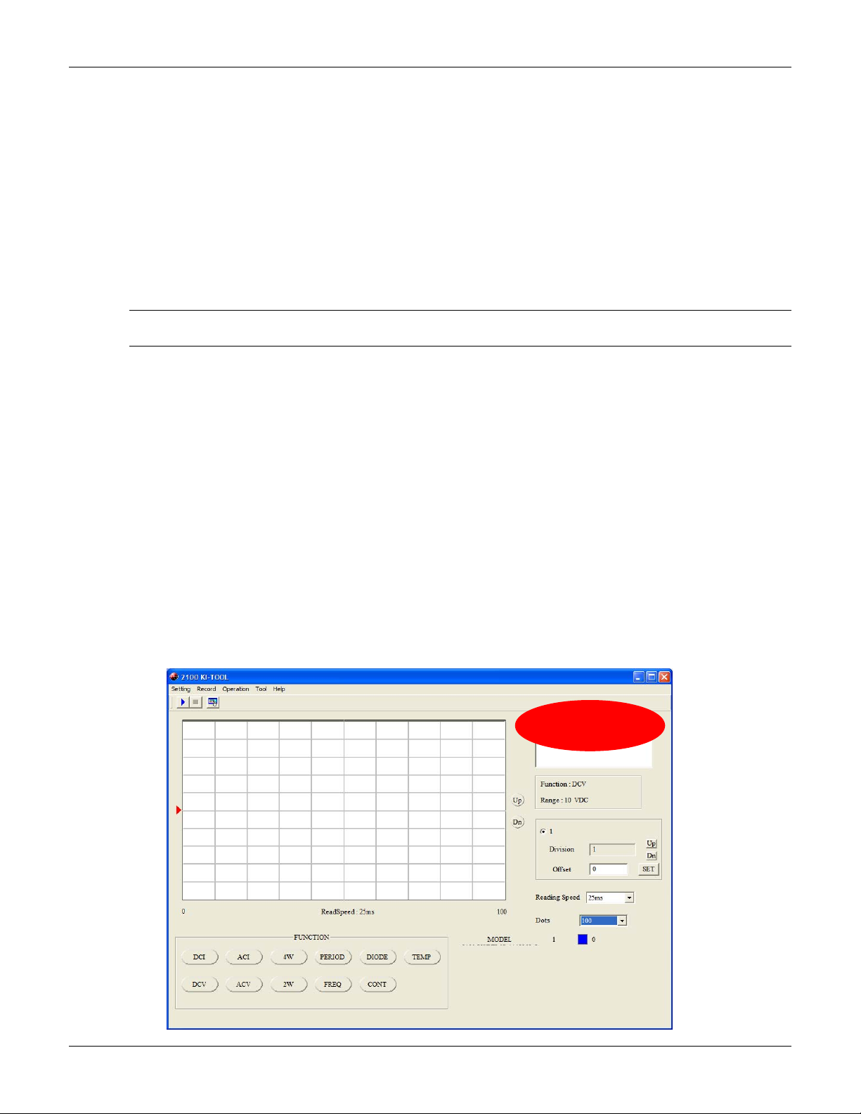
1. Install the USB device driver and KI-Tool Software from Keithley Instruments Model 2100
Product Information CD.
2. Connect the Model 2100 to the USB port and launch the KI-Tool application.
3. Verify that the correct model number is displayed in the upper right-hand corner window. See
Figure 1 for details.
Test the communications link between the Keithley Instruments Model 2100 and the control software by
clicking several function buttons and verifying that the DMM responds accordingly. See Figure 1 for more
details.
Figure 1
2100 KI-TOOL application
2 Model 2100 Calibration Manual Rev. A / April 2008
Page 9

Model 2100 Calibration Manual
The adjustment procedure consists of connecting Fluke 5700A Calibrator and Fluke 5725A Amplifier (or
equivalent) outputs to the Model 2100 front panel input, setting up appropriate ranges, and performing
adjustment functions by sending specific SCPI commands. In the following sections, you will be provided with
SCPI commands to be sent to the Model 2100. These commands should be entered into the Send String field
followed by the Write button. To access command control window from 2100 KI-TOOL application, click on
Tool > Command Control.
Note Be sure that the correct model number is selected before sending any SCPI commands.
Figure 2 shows the drop-down selection menu for the active units connected to the PC.
Environmental conditions
Conduct the calibration procedures in a location that has:
• An ambient temperature of 5°C to 40°C.
• A relative humidity of less than 80% unless otherwise noted.
Calibration considerations
When performing the calibration procedure:
• Make sure that the equipment is properly warmed up and connected to the appropriate input jacks.
Also make sure that the correct input jacks are selected with the INPUTS switch.
• Make sure the calibrator is in OPERATE before you complete each calibration step.
• Do not connect test equipment to the Model 2100 through a scanner or other switching equipment.
• If an error occurs during calibration, the Model 2100 will generate an appropriate error message.
Please refer to Model 2100 User’s Manual for error code descriptions.
• During the adjustment process the Model 2100 may not display the correct amplitude of the applied
signal. This condition is normal.
• After the adjustment procedure is completed, perform Section 3 (Performance Verification) to verify
that the Model 2100 is operating within the manufacturer’s specifications.
Recommended test equipment
Use a Fluke Model 5700A Calibrator and 5725A Amplifier (or the equivalent) to perform the Model 2100
multimeter adjustments.
Model 2100 Calibration Manual Rev. A / April 2008 3
Page 10
Model 2100 Calibration Manual
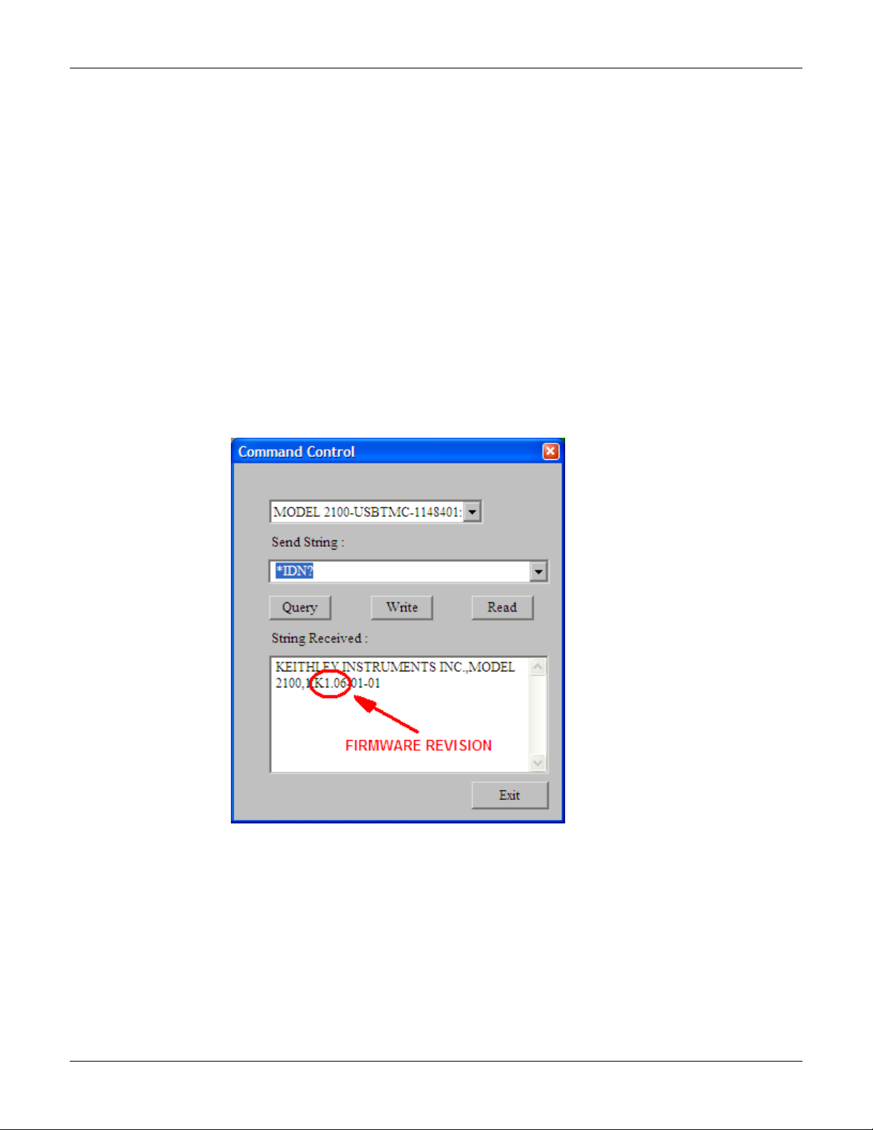
Firmware revision
If your Model 2100 has firmware versions 1.03 or 1.04, the firmware must be updated to the latest version
before this procedure can be performed. You may identify the firmware version as follows:
1. Press the QUERY button and enter the following SCPI command:
*IDN?
2. Figure 2 shows the typical location of the firmware version number. If the firmware requires
updating, refer to
Figure 2
Command Control Window
www.keithley.com for detailed instructions.
4 Model 2100 Calibration Manual Rev. A / April 2008
Page 11

Calibration code
Unlock the calibration routine by entering the following calibration code procedure:
1. Unlock the calibration function by sending the SCPI command:
CAL:PROT:CODE <up to 8-character string>
The default code command is:
CAL:PROT:CODE p8125652
2. Initiate the calibration routine by sending the SCPI command:
CAL:PROT:INIT
Model 2100 Calibration Manual
Zero calibration (front/rear)
Front panel zero calibration
1. Connect low thermal, 4-wire short (Keithley Instruments Model 8610 or equivalent) to the
instrument front panel input terminals.
2. Set INPUTS select switch to front terminals. Allow connections to stabilize for a minimum of
five minutes before proceeding.
Note Be sure to connect the low-thermal short properly to the HI, LO, and SENSE terminals.
Keep drafts away from low-thermal connections to avoid thermal drift, which could affect
calibration accuracy.
3. Initiate the Model 2100 zero calibration by sending the following SCPI command:
4. Wait until the following message is displayed on the Model 2100 display:
CAL:PROT:DC:STEP 3,0
Cali OK
Model 2100 Calibration Manual Rev. A / April 2008 5
Page 12

Model 2100 Calibration Manual
Rear panel zero calibration
1. Connect low thermal, 4-wire short (Keithley Instruments Model 8610 or equivalent) to the
instrument rear panel input terminals.
2. Set INPUTS select switch to rear terminals. Allow connections to stabilize for a minimum of five
minutes before proceeding.
3. Initiate the Model 2100 zero calibration by sending the following SCPI command:
4. Wait until the following message is displayed on the Model 2100 display:
5. Remove the low thermal, 4-wire short from the rear terminals.
6. Set the INPUTS select switch to front terminals.
CAL:PROT:DC:STEP 4,0
Cali OK
Voltage function adjustment (DC and AC)
The ranges for DC voltage (DCV) adjustment are 100mV, 1V, 10V, 100V, and 1000V. For AC voltage (ACV)
adjustment, the ranges are 100mV, 1V, 10V, 100V, and 750V RMS at 1kHz.
WARNING Do not apply more than 1 000V (peak) to the Model 2100 multimeter. Applying excess
voltage may damage the meter or cause electric shock, resulting in personal injury
or death.
Note
DC voltage range adjustment
1. Set the 5700A to 0V DC, RANGE: AUTO and output to STANDBY mode.
2. Using shielded, low thermal EMF cables connect the Fluke 5700A output HI and LO to Model
3. Configure the Model 2100 to 10V DC voltage range by sending the following SCPI command:
4. Set the 5700A output mode to OPERATE.
5. Adjust the input offset by sending the following SCPI command:
To eliminate the thermal EMFs due to the differences between two metals, use copper
leads to connect your source signal to the meter.
2100 input HI and LO terminals. Allow connections to stabilize for a minimum of five minutes
before proceeding.
CONF:VOLT:DC 10
6 Model 2100 Calibration Manual Rev. A / April 2008
Page 13

Model 2100 Calibration Manual
CAL:PROT:DC:STEP 1,10
6. Wait until the following message is displayed on the Model 2100 display:
Cali OK
7. Set the 5700A output to 10V DC.
8. Adjust the full scale measurement by sending the following SCPI command:
CAL:PROT:DC:STEP 2,10
9. Wait until the following message is displayed on the Model 2100 display:
Cali OK
10. Set the 5700A output mode to STANDBY.
11. Configure the Model 2100 to 1V range by sending the following SCPI command:
CONF:VOLT:DC 1
12. Set the 5700A 0V DC and output to OPERATE mode.
13. Adjust the input offset by sending the following SCPI command:
CAL:PROT:DC:STEP 1,1
14. Wait until the following message is shown on the Model 2100 display:
Cali OK
15. Set the 5700A output to 1V DC.
16. Adjust the full scale measurement by sending the following SCPI command:
CAL:PROT:DC:STEP 2,1
17. Wait until the following message is shown on the Model 2100 display:
Cali OK
18. Set the 5700A output mode to STANDBY.
19. Configure the Model 2100 to 0.1V range by sending the following SCPI command:
CONF:VOLT:DC 0.1
20. Set the 5700A to 0V DC and output to OPERATE mode.
21. Adjust the input offset by sending the following SCPI command:
CAL:PROT:DC:STEP 1,0.1
22. Wait until the following message is shown on the Model 2100 display:
Cali OK
Model 2100 Calibration Manual Rev. A / April 2008 7
Page 14

Model 2100 Calibration Manual
23. Set the 5700A output to 0.1V DC.
24. Adjust the full scale measurement by sending the following SCPI command:
25. Wait until the following message is shown on the Model 2100 display:
26. Set the 5700A output mode to STANDBY.
27. Configure the Model 2100 to 100V range by sending the following SCPI command:
28. Set 5700A to 0V DC and output to OPERATE mode.
29. Adjust input offset by sending the following SCPI command:
Wait until the following message is displayed on the Model 2100 display:
30. Set the 5700A output to 100V DC.
31. Adjust the full scale measurement by sending the following SCPI command:
32. Wait until the following message is displayed on the Model 2100 display:
33. Set the 5700A output mode to STANDBY.
34. Configure the Model 2100 to 1000V range by sending the following SCPI command:
35. Set the 5700A to 0V DC and output to OPERATE mode.
36. Adjust the input offset by sending the following SCPI command:
37. Wait until the following message is displayed on the Model 2100 display:
38. Set the 5700A output to 1000V DC.
39. Adjust the full scale measurement by sending the following SCPI command:
40. Wait until the following message is displayed on the Model 2100 display:
CAL:PROT:DC:STEP 2,0.1
Cali OK
CONF:VOLT:DC 100
CAL:PROT:DC:STEP 1,100
Cali OK
CAL:PROT:DC:STEP 2,100
Cali OK
CONF:VOLT:DC 1000
CAL:PROT:DC:STEP 1,1000
Cali OK
CAL:PROT:DC:STEP 2,1000
8 Model 2100 Calibration Manual Rev. A / April 2008
Page 15

Model 2100 Calibration Manual
Cali OK
41. Set the 5700A to 0V DC and output mode to STANDBY.
AC voltage range adjustment
1. Set the 5700A to 0.01V at 1kHz and output to STANDBY mode.
2. Using coaxial cable with dual banana terminals connect the Fluke 5700A output HI and LO
to the Model 2100 input HI and LO terminals. Allow connections to stabilize for a minimum
of five minutes before proceeding.
3. Configure the Model 2100 to 0.1V range by sending the following SCPI command:
CONF:VOLT:AC 0.1
4. Set the 5700A output mode to OPERATE.
5. Adjust 10% of the range by sending the following SCPI command:
CAL:PROT:AC:STEP 1,0.01
6. Wait until the following message is displayed on the Model 2100 display:
Cali OK
7. Set the 5700A output to 0.1V.
8. Adjust the full scale measurement by sending the following SCPI command:
CAL:PROT:AC:STEP 2,0.1
9. Wait until the following message is displayed on the Model 2100 display:
Cali OK
10. Set the 5700A output mode to STANDBY.
11. Configure the Model 2100 to 1V range by sending the following SCPI command:
CONF:VOLT:AC 1
12. Set the 5700A to 0.1V and output mode to OPERATE.
13. Adjust 10% of the range by sending the following SCPI command:
CAL:PROT:AC:STEP 1,0.1
14. Wait until the following message is displayed on the Model 2100 display:
Cali OK
15. Set the 5700A output to 1V.
16. Adjust the full scale measurement by sending the following SCPI command:
CAL:PROT:AC:STEP 2,1
Model 2100 Calibration Manual Rev. A / April 2008 9
Page 16

Model 2100 Calibration Manual
17. Wait until the following message is displayed on the Model 2100 display:
18. Set the5700A output mode to STANDBY.
19. Configure the Model 2100 to 10V range by sending the following SCPI command:
20. Set the 5700A to 1V and output mode to OPERATE.
21. Adjust 10% of the range by sending the following SCPI command:
22. Wait until the following message is displayed on the Model 2100 display:
23. Set the 5700A output to 10V.
24. Adjust the full scale measurement by sending the following SCPI command:
25. Wait until the following message is displayed on the Model 2100 display:
26. Set the 5700A output mode to STANDBY.
27. Configure the Model 2100 to 100V range by sending the following SCPI command:
28. Set the 5700A to 10V and output mode to OPERATE.
29. Adjust 10% of the range by sending the following SCPI command:
30. Wait until the following message is displayed on the Model 2100 display:
31. Set the 5700A output to 100V.
32. Adjust the full scale measurement by sending the following SCPI command:
33. Wait until the following message is displayed on the Model 2100 display:
Cali OK
CONF:VOLT:AC 10
CAL:PROT:AC:STEP 1,1
Cali OK
CAL:PROT:AC:STEP 2,10
Cali OK
CONF:VOLT:AC 100
CAL:PROT:AC:STEP 1,10
Cali OK
CAL:PROT:AC:STEP 2,100
Cali OK
10 Model 2100 Calibration Manual Rev. A / April 2008
Page 17

Model 2100 Calibration Manual
34. Set the 5700A output mode to STANDBY.
35. Configure the Model 2100 to 750V range by sending the following SCPI command:
CONF:VOLT:AC 750
36. Set the 5700A to 75V and output mode to OPERATE.
37. Adjust 10% of the range by sending the following SCPI command:
CAL:PROT:AC:STEP 1,75
38. Wait until the following message is displayed on the Model 2100 display:
Cali OK
39. Set the 5700A output to 750V.
40. Adjust the full scale measurement by sending the following SCPI command:
CAL:PROT:AC:STEP 2,750
41. Wait until the following message is displayed on the Model 2100 display:
Cali OK
42. Set the 5700A output mode to STANDBY. Press the RESET button on the 5700A front
panel to reset the calibrator to its default settings.
Model 2100 Calibration Manual Rev. A / April 2008 11
Page 18

Model 2100 Calibration Manual
Ohms function adjustment
Resistance low range adjustment (100Ω - 1MΩ)
1. Set the 5700A to 0
output to STANDBY mode.
2. Using shielded, low thermal EMF cables connect Fluke 5700A output HI and LO to Model
2100 input HI and LO terminals. Allow connections to stabilize for a minimum of five
minutes before proceeding.
3. Configure the Model 2100 for 2-wire, 1M
SCPI command:
4. Set the measurement rate to 10 PLC by sending the following SCPI command:
5. Set the average function to 100 counts by sending the following SCPI command:
6. Set the 5700A output mode to OPERATE.
7. Adjust the input offset by sending the following SCPI command:
8. Wait until the following message is displayed on the Model 2100 display:
9. Set the 5700A output to 1M
10. Adjust the full scale measurement by sending the following SCPI command:
CAL:PROT:DC:STEP 2,<ACTUAL CALIBRATOR OUTPUT>
, 2 WIRE COMP OFF, EX SNS button off, EX GRD button off, and
resistance function by sending the following
CONF:RES 1E6
RES:NPLC 10
AVERAGE:COUNT 100
CAL:PROT:DC:STEP 1,1E6
Cali OK
.
Note Enter the actual output value in scientific notation format. For example, if the calibrator’s
display shows 0.9999615 M, enter this value as:
CAL:PROT:DC:STEP 2,0.9999615E6
11. Wait until the following message is displayed on the Model 2100 display:
Cali OK
12. Set the 5700A output mode to STANDBY.
12 Model 2100 Calibration Manual Rev. A / April 2008
Page 19

Model 2100 Calibration Manual
13. Set the 5700A to 0, 2 WIRE COMP OFF, EX SNS button on, EX GRD button off, and
output to STANDBY mode.
14. Using shielded, low thermal EMF cables connect Fluke 5700A output HI, output LO, sense
HI, sense LO to Model 2100 input HI, input LO, sense HI, and sense LO terminals. Allow
connections to stabilize for a minimum of five minutes before proceeding.
15. Configure the Model 2100 for 4-wire, 1M
SCPI command:
resistance function by sending the following
CONF:FRES 1E6
16. Set the measurement rate to 10 PLC by sending the following SCPI command:
FRES:NPLC 10
17. Set the average function to 100 counts by sending the following SCPI command:
AVERAGE:COUNT 100
18. Set the 5700A output mode to OPERATE.
19. Adjust the input offset by sending the following SCPI command:
CAL:PROT:DC:STEP 1,1E6
20. Wait until the following message is displayed on the Model 2100 display:
Cali OK
21. Set the 5700A output to 1M
22. Adjust the full scale measurement by sending the following SCPI command:
.
CAL:PROT:DC:STEP 2,<ACTUAL CALIBRATOR OUTPUT>
23. Wait until the following message is displayed on the Model 2100 display:
Cali OK
24. Set the 5700A output mode to STANDBY.
25. Configure the Model 2100 for 4-wire, 100k
SCPI command:
resistance function by sending the following
CONF:FRES 1E5
26. Set the measurement rate to 10 PLC by sending the following SCPI command:
FRES:NPLC 10
27. Set the average function to 25 counts by sending the following SCPI command:
AVERAGE:COUNT 25
Model 2100 Calibration Manual Rev. A / April 2008 13
Page 20

Model 2100 Calibration Manual
28. Set the 5700A to 0 and output mode to OPERATE.
29. Adjust the input offset by sending the following SCPI command:
30. Wait until the following message is displayed on the Model 2100 display:
31. Set the 5700A output to 100k
32. Adjust the full scale measurement by sending the following SCPI command:
33. Wait until the following message is displayed on the Model 2100 display:
34. Set the 5700A output mode to STANDBY.
35. Configure the Model 2100 for 4-wire, 10k
SCPI command:
36. Set the measurement rate to 10 PLC by sending the following SCPI command:
37. Set the 5700A to 0 and output mode to OPERATE.
38. Adjust the input offset by sending the following SCPI command:
39. Wait until the following message is displayed on the Model 2100 display:
40. Set the 5700A output to 10k
41. Adjust the full scale measurement by sending the following SCPI command:
42. Wait until the following message is displayed on the Model 2100 display:
43. Set the 5700A output mode to STANDBY.
44. Configure the Model 2100 for 4-wire, 1k
SCPI command:
CAL:PROT:DC:STEP 1,1E5
Cali OK
.
CAL:PROT:DC:STEP 2,<ACTUAL CALIBRATOR OUTPUT>
Cali OK
resistance function by sending the following
CONF:FRES 1E4
FRES:NPLC 10
CAL:PROT:DC:STEP 1,1E4
Cali OK
.
CAL:PROT:DC:STEP 2,<ACTUAL CALIBRATOR OUTPUT>
Cali OK
resistance function by sending the following
14 Model 2100 Calibration Manual Rev. A / April 2008
Page 21

Model 2100 Calibration Manual
CONF:FRES 1E3
45. Set measurement rate to 10 PLC by sending the following SCPI command:
FRES:NPLC 10
46. Set the 5700A to 0 and output mode to OPERATE.
47. Adjust the input offset by sending the following SCPI command:
CAL:PROT:DC:STEP 1,1E3
48. Wait until the following message is displayed on the Model 2100 display:
Cali OK
49. Set the 5700A output to 1k
50. Adjust the full scale measurement by sending the following SCPI command:
.
CAL:PROT:DC:STEP 2,<ACTUAL CALIBRATOR OUTPUT>
51. Wait until the following message is displayed on the Model 2100 display:
Cali OK
52. Set the 5700A output mode to STANDBY.
53. Configure the Model 2100 for 4-wire, 100
SCPI command:
resistance function by sending the following
CONF:FRES 1E2
54. Set the measurement rate to 10 PLC by sending the following SCPI command:
FRES:NPLC 10
55. Set the 5700A to 0 and output mode to OPERATE.
56. Adjust the input offset by sending the following SCPI command:
CAL:PROT:DC:STEP 1,1E2
57. Wait until the following message is displayed on the Model 2100 display:
Cali OK
58. Set the 5700A output to 100
59. Adjust the full scale measurement by sending the following SCPI command:
.
CAL:PROT:DC:STEP 2,<ACTUAL CALIBRATOR OUTPUT>
60. Wait until the following message is displayed on the Model 2100 display:
Model 2100 Calibration Manual Rev. A / April 2008 15
Page 22

Model 2100 Calibration Manual
61. Set the 5700A output mode to STANDBY.
Resistance high range adjustment (10MΩ - 100MΩ)
1. Set the 5700A to 0
output to STANDBY mode.
2. Using shielded, low thermal EMF cables connect the Fluke 5700A output HI, output LO,
sense HI, and sense LO to the Model 2100 input HI, input LO, sense HI, and sense LO
terminals. Allow connections to stabilize for a minimum of five minutes before proceeding.
3. Configure the Model 2100 for 4-wire, 10M
SCPI command:
4. Set the measurement rate to 10 PLC by sending the following SCPI command:
5. Set the average function to 100 counts by sending the following SCPI command:
6. Set the 5700A output mode to OPERATE.
7. Adjust the input offset by sending the following SCPI command:
8. Wait until the following message is displayed on the Model 2100 display:
9. Set the 5700A output to 10M
10. Adjust the full scale measurement by sending the following SCPI command:
11. Wait until the following message is displayed on the Model 2100 display:
12. Set the 5700A output mode to STANDBY.
13. Set the 5700A to 0
output to STANDBY mode.
14. Using shielded, low thermal EMF cables connect the Fluke 5700A output HI and output LO
to the Model 2100 input HI and input LO terminals. Allow connections to stabilize for a
minimum of five minutes before proceeding.
15. Configure the Model 2100 for 2-wire, 10M
SCPI command:
Cali OK
, 2 WIRE COMP OFF, EX SNS button on, EX GRD button off, and
resistance function by sending the following
CONF:FRES 10E6
FRES:NPLC 10
AVERAGE:COUNT 100
CAL:PROT:DC:STEP 1,10E6
Cali OK
.
CAL:PROT:DC:STEP 2,<ACTUAL CALIBRATOR OUTPUT>
Cali OK
, 2 WIRE COMP OFF, EX SNS button off, EX GRD button off, and
resistance function by sending the following
16 Model 2100 Calibration Manual Rev. A / April 2008
Page 23

Model 2100 Calibration Manual
CONF:RES 10E6
16. Set the measurement rate to 10 PLC by sending the following SCPI command:
RES:NPLC 10
17. Set the average function to 100 counts by sending the following SCPI command:
AVERAGE:COUNT 100
18. Set the 5700A output mode to OPERATE.
19. Adjust the input offset by sending the following SCPI command:
CAL:PROT:DC:STEP 1,10E6
20. Wait until the following message is displayed on theModel 2100 display:
Cali OK
21. Set the 5700A output to 10M
22. Adjust the full scale measurement by sending the following SCPI command:
.
CAL:PROT:DC:STEP 2,<ACTUAL CALIBRATOR OUTPUT>
23. Wait until the following message is displayed on the Model 2100 display:
Cali OK
24. Set the 5700A output mode to STANDBY.
25. Configure the Model 2100 for 2-wire, 100M
SCPI command:
resistance function by sending the following
CONF:RES 100E6
26. Set the measurement rate to 10 PLC by sending the following SCPI command:
RES:NPLC 10
27. Set the average function to 25 counts by sending the following SCPI command:
AVERAGE:COUNT 25
28. Set the 5700A to 0 and output mode to OPERATE.
29. Adjust the input offset by sending the following SCPI command:
CAL:PROT:DC:STEP 1,100E6
30. Wait until the following message is displayed on the Model 2100 display:
Cali OK
Model 2100 Calibration Manual Rev. A / April 2008 17
Page 24

Model 2100 Calibration Manual
31. Set the 5700A to 100M and output to STANDBY.
32. Adjust the full scale measurement by sending the following SCPI command:
CAL:PROT:DC:STEP 2,99.99750
33. Wait until the following message is displayed on the Model 2100 display:
Cali OK
Current function adjustment (DC and AC)
DC current range adjustment
1. Set the 5700A to 0A, CURRNT OUTPUT: 5725, RANGE: AUTO, and output to STANDBY
mode.
2. Using shielded, low thermal EMF cables, connect the Fluke 5725A current output HI and
output LO to the Model 2100 input AMPS and input LO terminals. Allow connections to
stabilize for a minimum of five minutes before proceeding.
3. Configure Model 2100 to 0.01A DC current range by sending the following SCPI command:
CONF:CURR:DC 0.01
4. Set the measurement rate to 10 PLC by sending the following SCPI command:
CURR:NPLC 10
5. Set the 5700A output mode to OPERATE.
6. Adjust the front input offset by sending the following SCPI command:
CAL:PROT:DC:STEP 1,0.01
7. Wait until the following message is displayed on the Model 2100 display:
Cali OK
8. Set the 5700A output to 0.01A DC.
9. Adjust the full scale measurement by sending the following SCPI command:
CAL:PROT:DC:STEP 2,0.01
10. Wait until the following message is displayed on the Model 2100 display:
Cali OK
11. Set the 5700A output mode to STANDBY.
12. Configure the Model 2100 to 0.1A DC current range by sending the following SCPI
command:
CONF:CURR:DC 0.1
18 Model 2100 Calibration Manual Rev. A / April 2008
Page 25

Model 2100 Calibration Manual
13. Set the measurement rate to 10 PLC by sending the following SCPI command:
CURR:NPLC 10
14. Set the 5700A to 0A and output mode to OPERATE.
15. Adjust the front input offset by sending the following SCPI command:
CAL:PROT:DC:STEP 1,0.1
16. Wait until the following message is displayed on the Model 2100 display:
Cali OK
17. Set the 5700A output to 0.06A DC.
18. Adjust the mid-region of the range by sending the following SCPI command:
CAL:PROT:DC:STEP 2,0.06
19. Wait until the following message is displayed on the Model 2100 display:
Cali OK
20. Set the 5700A output to 0.12A DC.
21. Adjust the full scale measurement by sending the following SCPI command:
CAL:PROT:DC:STEP 2,0.12
22. Wait until the following message is displayed on the Model 2100 display:
Cali OK
23. Set the 5700A output mode to STANDBY.
24. Configure the Model 2100 to 1A DC current range by sending the following SCPI
command:
CONF:CURR:DC 1
25. Set the measurement rate to 10 PLC by sending the following SCPI command:
CURR:NPLC 10
26. Set the 5700A to 0A and output mode to OPERATE.
27. Adjust the front input offset by sending the following SCPI command:
CAL:PROT:DC:STEP 1,1
28. Wait until the following message is displayed on the Model 2100 display:
Cali OK
Model 2100 Calibration Manual Rev. A / April 2008 19
Page 26

Model 2100 Calibration Manual
29. Set the 5700A output to 1A DC.
30. Adjust the full scale measurement by sending the following SCPI command:
31. Wait until the following message is displayed on the Model 2100 display:
32. Set the 5700A output mode to STANDBY. Press RESET button on 5700A front panel to
reset the calibrator to its default settings.
AC current range adjustment
1. Set the 5700A to 0.1A at 1kHz, CURRNT OUTPUT: 5725, and output to STANDBY mode.
2. Using coaxial cable with dual banana terminals connect the Fluke 5725A current output HI
and LO to the Model 2100 input AMPS and LO terminals. Allow connections to stabilize for
a minimum of five minutes before proceeding.
3. Configure the Model 2100 to 1A AC current range by sending the following SCPI
command:
4. Set the 5700A output mode to OPERATE.
5. Adjust 10% of the range by sending the following SCPI command:
6. Wait until the following message is displayed on the Model 2100 display:
7. Set the 5700A output to 1A at 1kHZ.
8. Adjust the full scale range by sending the following SCPI command:
9. Wait until the following message is displayed on the Model 2100 display:
10. Set the 5700A output to 0.01A at 1kHZ.
11. Adjust 1% of the range by sending the following SCPI command:
12. Wait until the following message is displayed on the Model 2100 display:
CAL:PROT:DC:STEP 2,1
Cali OK
CONF:CURR:AC 1
CAL:PROT:AC:STEP 1,0.1
Cali OK
CAL:PROT:AC:STEP 2,1
Cali OK
CAL:PROT:AC:STEP 3,0.01
Cali OK
20 Model 2100 Calibration Manual Rev. A / April 2008
Page 27

Model 2100 Calibration Manual
13. Set the 5700A output mode to STANDBY.
14. Configure the Model 2100 to the 3A AC current range by sending the following SCPI
command:
CONF:CURR:AC 3
15. Set the 5700A to 0.2A at 1kHz and output mode to OPERATE.
16. Adjust the lower region of the range by sending the following SCPI command:
CAL:PROT:AC:STEP 1,0.2
17. Wait until the following message is displayed on the Model 2100 display:
Cali OK
18. Set the 5700A output to 2A at 1kHZ.
19. Adjust the upper region of the range by sending the following SCPI command:
CAL:PROT:AC:STEP 2,2
20. Wait until the following message is displayed on the Model 2100 display:
Cali OK
21. Set the 5700A output mode to STANDBY. Press RESET button on the 5700A front panel
to reset the calibrator to its default settings.
Model 2100 Calibration Manual Rev. A / April 2008 21
Page 28

Model 2100 Calibration Manual
Calibration date
1. Update the calibration date by sending the following SCPI command:
Note The date <string> must be enclosed in double quotes (“<string>”). Example: if calibration
date is 1 Jan 2008, send the following SCPI command:
2. Save the calibration constants in EEPROM by sending the following SCPI command:
3. Lock the calibration function by sending the following SCPI command:
CAL:PROT:DATE <”MM/DD/YYYY”>
CAL:PROT:DATE ”01/01/2008”
Calibration due date is automatically calculated for 12 months.
CAL:PROT:SAVE
CAL:PROT:LOCK
Performance verification
Note After adjustment is completed, the Model 2100 must be verified to ensure that its
performance is within manufacturer’s specifications.
Perform accuracy verifications using Fluke 5700A and 5725A standards and a function generator capable of
sourcing frequency with an accuracy of 25 ppm or better. Refer to Tables 1 through 6 for limits of accuracy on
specified ranges.
Table 1
DC voltage accuracy verification
Range Test Point
100 mV
1 V
10 V
100 V
1000 V
Specifications valid after 2-hour warm-up:
a. ADC set for continuous trigger operation.
b. Input bias current: <30pA at 25 °C.
c. Input protection: 1000V all ranges (2-W input).
d. Measurement rate set to 1 PLC.
100.0000 mV 99.9905 mV 100.0095 mV
-100.0000 mV -100.0095 mV -99.9905 mV
1.000000 V 0.999947 V 1.000053 V
-1.000000 V -1.000053 V -0.999947 V
10.00000 V 9.99956 V 10.00044 V
-10.00000 V -10.00044 V -9.99956 V
100.0000 V 99.9943 V 100.0057 V
-100.0000 V -100.0057 V -99.9943 V
1000.000 V 999.935 V 1000.065 V
-1000.000 V -1000.065 V -999.935 V
Limits of Accuracy
Lower Limit Upper Limit
22 Model 2100 Calibration Manual Rev. A / April 2008
Page 29

Table 2
AC voltage accuracy verification
Range Test Point
100 mV
1 V
10 V
100 V
750 V
* Note: verify this point instead of 700 V if a Fluke 5725A is not available.
Specifications valid for 2-hour warm-up at 6½ digits:
a. Slow ac filter (3Hz bandwidth).
b. Pure sine wave input greater than 5% of range.
Table 3
Resistance accuracy verification
Range Test Point
100 Ω 100.0000 Ω 99.9755 Ω 100.0155 Ω
1 kΩ 1.000000 kΩ 0.999837 kΩ 1.000177 kΩ
10 kΩ 10.00000 kΩ 9.99863 kΩ 10.00163 kΩ
100 kΩ 100.0000 kΩ 99.9831 kΩ 100.0171 kΩ
1 MΩ 1.000000 MΩ 0.999784 MΩ 1.000164 MΩ
10 MΩ 10.00000 MΩ 9.99475 MΩ 10.00415 MΩ
100 MΩ 100.0000 MΩ 98.9817 MΩ 101.0218 MΩ
a. Specifications for 4-W Ohms mode (for 2-W Ohms, use zero null or subtract lead resistance
from displayed reading).
b. Max lead resistance is 10% of range per lead for 100 Ω and 1 kΩ ranges; add 1 kΩ per lead for
all other ranges.
Model 2100 Calibration Manual
Limits of Accuracy
Lower Limit Upper Limit
100.0000 mV @ 1 kHz 99.87 mV 100.13 mV
100.0000 mV @ 35 kHz 99.79 mV 100.21 mV
1.000000 V @ 1 kHz 0.9988 V 1.0012 V
1.000000 V @ 35 kHz 0.998 V 1.002 V
10.00000 V @ 1 kHz 9.988 V 10.012 V
10.00000 V @ 35 kHz 9.98 V 10.02 V
100.0000 V @ 1 kHz 99.88 V 100.12 V
100.0000 V @ 35 kHz 99.8 V 100.2 V
700.0000 V @ 1 kHz 699.14 V 700.86 V
700.000 V @ 35 kHz 698.57 V 701.43 V
* 220.000 V @ 35 kHz 219.24 V 220.76 V
Limits of Accuracy
Lower Limit Upper Limit
Model 2100 Calibration Manual Rev. A / April 2008 23
Page 30

Model 2100 Calibration Manual
Table 4
DC current accuracy verification
Range Test Point
10 mA
100 mA
1 A
* 2.1 A
3 A
Note: Verify this point instead of 3 A range if a Fluke 5725A is not available.
Specifications valid after 2-hour warm-up:
a. ADC set for continuous trigger operation.
b. Input bias current: <30pA at 25 °C.
c. Input protection: 1000V all ranges (2-W input).
d. Measurement rate set to 1 PLC.
Table 5
AC current accuracy verification
Range Test Point
1 A 1.000000 A @ 1 kHz 0.998 A 1.002 A
* 2.1 A 2.10000 A @ 1 kHz 2.0937 A 2.1063 A
3 A 3.00000 A @ 1 kHz 2.9919 A 3.0081 A
* Note: verify this point instead of 3 A range if Fluke 5725A is not available.
Specifications valid for 2-hour warm-up at 6½ digits:
a. Slow ac filter (3Hz bandwidth).
b. Pure sine wave input greater than 5% of range.
Table 6
Frequency accuracy verification
Range Test Point
3 Hz 3.000000 Hz @ 1 Vpp 2.997 Hz 3.003 Hz
300 kHz 300.0000 kHz @ 1 Vpp 299.97 kHz 300.03 kHz
Specifications valid for 2-hour warm-up at 6½ digits:
a. Slow ac filter (3Hz bandwidth).
b. Pure sine wave input greater than 5% of range.
Limits of Accuracy
Lower Limit Upper Limit
10.00000 mA 9.992 mA 10.008 mA
-10.00000 mA -10.008 mA -9.992 mA
100.0000 mA 99.939 mA 100.061 mA
-100.0000 mA -100.061 mA -99.939 mA
1.000000 A 0.99865 A 1.00135 A
-1.000000 A -1.00135 A -0.99865 A
2.10000 A 2.0961 2.1039
-2.10000 A -2.1039 -2.0961
3.00000 A 2.99475 A 3.00525 A
-3.00000 A -3.00525 A -2.99475 A
Limits of Accuracy
Lower Limit Upper Limit
Limits of Accuracy
Lower Limit Upper Limit
24 Model 2100 Calibration Manual Rev. A / April 2008
Page 31

Service Form
Model No. Serial No. Date
Name and Telephone No.
Company
List all control settings, describe problem and check boxes that apply to problem.
❏ Intermittent ❏ Analog output follows display ❏ Particular range or function bad; specify
❏ IEEE failure ❏ Obvious problem on power-up ❏ Batteries and fuses are OK
❏ Front panel operational ❏ All ranges or functions are bad ❏ Checked all cables
Display or output (check one)
❏ Drifts ❏ Unable to zero
❏ Unstable ❏ Will not read applied input
❏ Overload
❏ Calibration only ❏ Certificate of calibration required
❏ Data required
(attach any additional sheets as necessary)
Show a block diagram of your measurement system including all instruments connected (whether power is turned on
or not). Also, describe signal source.
Where is the measurement being performed? (factory, controlled laboratory, out-of-doors, etc.)
What power line voltage is used? Ambient temperature?°F
Relative humidity? Other?
Any additional information. (If special modifications have been made by the user, please describe.)
Be sure to include your name and phone number on this service form.
12/06
Page 32

Page 33

Page 34

12/06
Specifications are subject to change without notice.
All Keithley trademarks and trade names are the property of Keithley Instruments, Inc.
All other trademarks and trade names are the property of their respective companies.
A GREATER MEASURE OF CONFIDENCE
Keithley Instruments, Inc.
Corporate Headquarters • 28775 Aurora Road • Cleveland, Ohio 44139 • 440-248-0400 • Fax: 440-248-6168 • 1-888-KEITHLEY • www.keithley.com
 Loading...