


www.keithley.com
A GREATER MEASURE OF CONFIDENCE
Model 2100 6 1/2-Digit Resolution
Digit al Multimeter
User’s Manual
2100-900-01 Rev. E / March 2012

Model 2100
6 1/2-Digit Resolution Digital Multimeter
User’s Manual
©2007-2012, Keithley Instruments, Inc.
Document Number:
All rights reserved.
Cleveland, Ohio, U.S.A.
2100-900-01 Rev. E / March 2012


Safety Precautions
The following safety precautions should be observed before using this product an d any associated instrumentation. Although some
instruments and accessories would normally be used with nonhazardous voltages, there are situations where hazardous conditions may
be present.
This product is intended for use by qualified personnel who recognize shock hazards and are familiar with the safety precautions required
to avoid possible injury. Read and follow all installation, operation, and maintenance information carefully before using the product. Refer
to the user documentation for complete product specifications.
If the product is used in a manner not specified, the protection provided by the product warranty may be impaired.
The types of product users are:
Responsible body is the individual or group responsible for the use and maintenance of equipment, for ensuring that the equipment is
operated within its specifications and operating limits, and for ensuring that operators are adequately trained.
Operators use the product for its intended function. They must be trained in electrical safety procedures and proper use of the instrument.
They must be protected from electric shock and contact with hazardous live circuits.
Maintenance personnel perform routine procedures on the product to keep it operating properly, for example, setting the line voltage or
replacing consumable materials. Maintenance procedures are described in the user documentation. The procedures explicitly state if the
operator may perform them. Otherwise, they should be performed only by service personnel.
Service personnel are trained to work on live circuits, perform safe installations, and repair products. Only properly trained service
personnel may perform installation and service procedures.
Keithley Instruments products are designed for use with electrical signals that are rate d Measurement Category I and Measurement
Category II, as described in the International Electrotechnical Commission (IEC) Standard IEC 60664. Most measurement, control, and
data I/O signals are Measurement Category I and must not be directly connected to mains voltage or to voltage sources with high transient
over-voltages. Measurement Category II connections require protection for high transient over-voltages often associated with local AC
mains connections. Assume all measurement, control, and data I/O connections are for connection to Category I sources unless otherwise
marked or described in the user documentation.
Exercise extreme caution when a shock hazard is present. Lethal voltage may be present on cable connector jacks or test fixtures. The
American National Standards Institute (ANSI) states that a shock hazard exists when voltage levels greater than 30 V RMS, 42.4 V peak,
or 60 V DC are present. A good safety practice is to expect that hazardous voltage is present in any unknown circuit before measuring.
Operators of this product must be protected from electric shock at all times. The responsible body must ensure that operators are
prevented access and/or insulated from every connection point. In some cases, connections must be exposed to potential human contact.
Product operators in these circumstances must be trained to protect themselves from the risk of electric shock. If the circuit is capable of
operating at or above 1000 V, no conductive part of the circuit may be exposed.
Do not connect switching cards directly to unlimited power circuits. They are intended to be used with impedance-limited sources. NEVER
connect switching cards directly to AC mains. When connecting sources to switching cards, install protective devices to limit f
and voltage to the card.
Before operating an instrument, ensure that the line cord is connected to a properly-grounded power receptacle. Inspect the connecting
cables, test leads, and jumpers for possible wear, cracks, or breaks before each use.
ault current
11/07

When installing equipment where access to the main power cord is restricted, such as rack mounting, a separate main input power
!
disconnect device must be provided in close proximity to the equipment and within easy reach of the operator.
For maximum safety, do not touch the product, test cables, or any other instruments while power is applied to the circuit under test.
ALW AYS remove power from the entire test system and discharge any capacitors before: Connecting or disconnecting cables or jumpers,
installing or removing switching cards, or making internal changes, such as installing or removing jumpers.
Do not touch any object that could provide a current path to the common side of the circuit under test or power line (earth) ground. Always
make measurements with dry hands while standing on a dry, insulated surface capable of withstanding the voltage being measured.
The instrument and accessories must be used in accordance with its specifications and operating instructions, or the safety of the
equipment may be impaired.
Do not exceed the maximum signal levels of the instruments and accessories, as defined in the specifications and operating information,
and as shown on the instrument or test fixture panels, or switching card.
When fuses are used in a product, replace with the same type and rating for continued protection against fire hazard.
Chassis connections must only be used as shield connections for measuring circuits, NOT as safety earth ground connections.
If you are using a test fixture, keep the lid closed while power is applied to the device under test. Safe operation requires the use of a lid
interlock.
If a screw is present, connect it to safety earth ground using the wire recommended in the user documentation.
The symbol on an instrument means caution, risk of danger. The user should refer to the operating instructions located in the user
documentation in all cases where the symbol is marked on the instrument.
The symbol on an instrument means caution, risk of electric shock. Use standard safety precautions to avoid personal contact with
these voltages.
The symbol on an instrument shows that the surface may be hot. Avoid personal contact to prevent burns.
The symbol indicates a connection terminal to the equipment frame.
If this symbol is on a product, it indicates that mercury is present in the display lamp. Please note that the lamp must be properly
disposed of according to federal, state, and local laws.
The WARNING heading in the user documentation explains dangers that might result in personal injury or death. Always read the
associated information very carefully before performing the indicated procedure.
The CAUTION heading in the user documentation explains hazards that could damage the instrument. Such damage may invalidate the
warranty.
Instrumentation and accessories shall not be connected to humans.
Before performing any maintenance, disconnect the line cord and all test cables.
T o maintain protection from electric shock and fire, replacement components in mains circuits - including the power transformer, test leads,
and input jacks - must be purchased from Keithley Instruments. Standard fuses with applicable national safety approvals may be used if
the rating and type are the same. Other components that are not safety-related may be purchased from other suppliers as long as they
are equivalent to the original component (note that selected parts should be purchased only through Keithley Instruments to maintain
accuracy and functionality of the product). If you are unsure about the applicability of a replacement component, call a Keithley Instruments
office for information.
To clean an instrument, use a damp cloth or mild, water-based cleaner. Clean the exterior of the instrument only. Do not apply cleaner
directly to the instrument or allow liquids to enter or spill on the instrument. Products that consist of a circuit board with no case or chassis
(e.g., a data acquisition board for installation into a computer) should never require cleaning if handled according to instructions. If the
board becomes contaminated and operation is affected, the board should be returned to the factory for proper cleaning/servicing
.

Table of Contents
Section T opic Page
1 General Information.............................................................................. 1-1
Introduction................................................................................................. 1-2
Feature overview........................................................................................ 1-2
Specifications.............................................................................................. 1-3
Manual addenda......................................................................................... 1-3
Precautions for operation............................................................................ 1-3
Upkeep of the Model 2100.......................................................................... 1-3
Safety information....................................................................................... 1-4
Safety symbols and terms.................................................................... 1-4
Inspection for damage................................................................................ 1-4
Shipment contents...................................................................................... 1-5
Instruction manual...................................................................................... 1-5
Repacking for shipment.............................................................................. 1-5
2 Getting Started....................................................................................... 2-1
Overview..................................................................................................... 2-2
Setting up the Model 2100 Digital Multimeter............................................. 2-2
Adjusting the handle............................................................................. 2-2
Setting the line voltage ......................................................................... 2-4
Connecting the power.......................................................................... 2-7
Changing the fuses.............................................................................. 2-9
Factory default settings...................................................................... 2-18
Model 2100 familiarization........................................................................ 2-19
The front panel................................................................................... 2-19
The display........................................................................................ 2-21
The rear panel.................................................................................... 2-23
3 Basic Measurement Functions........................................................... 3-1
Introduction................................................................................................. 3-2
Voltage measurements (DC and AC) ......................................................... 3-2
How to measure voltage....................................................................... 3-3
Current measurements (DC and AC) ......................................................... 3-3
How to measure current....................................................................... 3-3
Resistance measurements (2- and 4-wir e)................................................. 3-4
How to measure resistance.................................................................. 3-6
Frequency and period measurements........................................................ 3-6
How to measure frequency and period................................................ 3-6
Continuity measurements........................................................................... 3-7
How to measure the continuity............................................................. 3-7
Diode measurements.................................................................................. 3-7
How to measure a diode...................................................................... 3-8
RTD measurements.................................................................................... 3-8
2-wire RTD measurements .................................................................. 3-8
3-wire RTD measurements .................................................................. 3-9
4-wire RTD measurements ................................................................ 3-10
4 Front Panel Operations........................................................................ 4-1
Introduction................................................................................................. 4-2
Measurement configuration........................................................................ 4-2

Table of Contents Model 2100 6 1/2-Digit Resolution Digital Multimeter User’s Manual
Set ADC (Auto Zero and Auto Gain).................................................... 4-2
Filter ..................................................................................................... 4-4
Resolution setting (digits)..................................................................... 4-6
DC input resistance.............................................................................. 4-7
Threshold resistance (continuity).......................................................... 4-8
Range (manual and auto)..................................................................... 4-9
Rate (integration time)........................................................................ 4-10
Sensor selection for temperature.............................................................. 4-11
Measurements.................................................................................... 4-11
RTD.................................................................................................... 4-11
Input terminal switch........................................................................... 4-13
Trigger operations..................................................................................... 4-14
Trigger mode...................................................................................... 4-14
Trigger source .................................................................................... 4-16
Trigger setting..................................................................................... 4-18
Math operations........................................................................................ 4-20
Ratio................................................................................................... 4-21
% (Percent) ........................................................................................ 4-22
MIN/MAX............................................................................................ 4-23
Null..................................................................................................... 4-24
Limits test ........................................................................................... 4-25
MX+B.................................................................................................. 4-26
dB....................................................................................................... 4-27
dBm.................................................................................................... 4-29
Other system-related operations............................................................... 4-31
Display................................................................................................ 4-31
Beeper................................................................................................ 4-32
Reading memory (store and recall).................................................... 4-33
Sensitivity band (Hold) ....................................................................... 4-35
Initial mode......................................................................................... 4-35
Language ........................................................................................... 4-36
Error condition.................................................................................... 4-37
Firmware revision............................................................................... 4-38
Calibration .......................................................................................... 4-41
Self-test.............................................................................................. 4-41
5 Remote Interface Operations.............................................................. 5-1
Introduction................................................................................................. 5-2
Pass/fail output from the USB connector ............................................. 5-2
Setting up the remote interface................................................................... 5-2
Remote interface commands...................................................................... 5-3
Common commands............................................................................ 5-3
Other measurement configuration commands..................................... 5-7
Math operation commands................................................................... 5-7
Triggering.................................................................................................... 5-8
Triggering commands........................................................................... 5-8
System-related commands......................................................................... 5-9
Status reporting commands.................................................................. 5-9
Other interface commands................................................................. 5-10
6 Error Messages...................................................................................... 6-1
Introduction................................................................................................. 6-2
Execution errors.......................................................................................... 6-2
Self-test errors ............................................................................................ 6-4
A Remote Interface Reference................................................................ A-1
An introduction to SCPI language............................................................... A-2
Command format used in this manual.................................................. A-2
SCPI parameter types.......................................................................... A-4
Output data formats.............................................................................. A-5
The MEASure? command.................................................................... A-6
The CONFigure command ................................................................... A-7
The measurement configuration command.......................................... A-9
The math operation command ........................................................... A-14
ii 2100-900-01 Rev. E / March 2012

Model 2100 6 1/2-Digit Resolution Digital Multimeter User’s Manual Table of Contents
The triggering commands................................................................... A-17
The system-related commands.......................................................... A-18
Other interface commands................................................................. A-20
The SCPI status pattern..................................................................... A-20
Status reporting commands................................................................ A-26
Model 2100-specific SCPI compliance information............................ A-28
IEEE-488 compliance information...................................................... A-30
About application programs...................................................................... A-30
Visual Basic 6 programming example 1: MEASure.bas.................... A-30
Visual Basic programming example 2: CONFigur e....................... A-33
Visual C++ programming example: DEVQUERY............................... A-35
Visual C++ sample application........................................................... A-35
Index ........................................................................................................................... I-1
2100-900-01 Rev. E / March 2012 iii

Table of Contents Model 2100 6 1/2-Digit Resolution Digital Multimeter User’s Manual
This page left blank intentionally.
iv 2100-900-01 Rev. E / March 2012

In this section:
Topic Page
Introduction ......................................................................................... 1-2
Feature overview ................................................................................ 1-2
Specifications...................................................................................... 1-3
Manual addenda ................................................................................. 1-3
Precautions for operation.................................................................... 1-3
Upkeep of the Model 2100.................................................................. 1-3
Safety information............................................................................... 1-4
Inspection for damage ........................................................................ 1-4
Shipment contents .............................................................................. 1-5
Instruction manual............................................................................... 1-5
Repacking for shipment ...................................................................... 1-5
Section 1
General Information
Safety symbols and terms ............................................................ 1-4
Section 1: General Information Model 2100 6 1/2-Digit Resolution Digital Multimeter User’s Manual
Introduction
This section contains general information about the Keithley Instrument s Model 2100 6 1/2-Digit
Resolution Digital Multimeter. The information is organized as follows:
• Feature overview
• Manual addenda
• Precautions for operation
• Upkeep of the Model 2100
• Safety information
• Inspection for damage
• Shipment contents
• Instruction manual
• Repacking for shipment
If you have any questions after reviewing this information, please cont act your local Keithley
Instruments representative or call one of our Applications Engineers at 1-888-KEITHLEY
(1-888-534-8453). You can also contact us through our website at www.keithley.com.
Feature overview
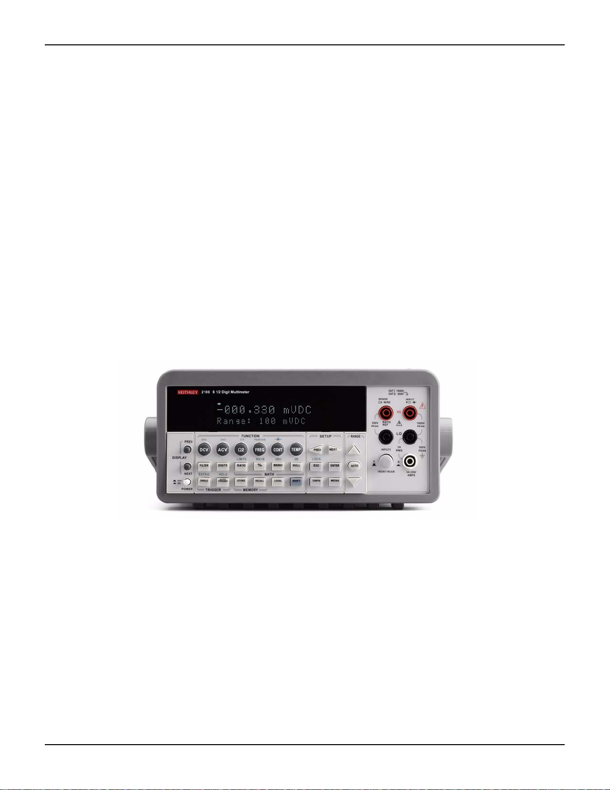
Figure 1-1
The Model 2100 6 1/2-Digit Resolution Digital Multimeter
The Keithley Instruments Model 2100 is a rugged and versatile 6 1/2-digit resolution digital
multimeter . It has 0.003% one-year basic DC volt age accura cy at 10V ra nge and 0.005 % one-year
basic resistance accuracy at 10kΩ range. At 6 1/2 digits, the multimeter delivers 50 triggered
RDGS/sec via the USB remote interface. At the fast 4 1/2-digit setting, it reads over 2000 RDGS/
sec into its internal buffer.
• Resolution: 6 1/2 digits
• 5x7 dot-matrix VFD, dual displays with 3-color annunciators
• Eleven standard measurement functions and eight math functions
• Stability, accuracy, and speed
• Built-in USB interfaces
• DC voltage: 0.1V, 1V, 10V, 100V, and 1000V
• AC voltage: 0.1V, 1V, 10V, 100V, and 750V
• DC current: 10mA, 100mA, 1A, and 3A
• AC current: 1A, and 3A
• Two and 4-wire resistance: 100Ω, 1KΩ , 10KΩ , 100KΩ , 1MΩ , 10MΩ, and 100MΩ
1-2 Return to Section Topics 2100-900-01 Rev. E / March 2012

Model 2100 6 1/2-Digit Resolution Digital Multimeter User’s Manual Section 1: General Information
• Frequency: From 3Hz to 300kHz
• Period measurement
• Diode measurement
• Continuity measurement for resistance
Some additional capabilities of the Model 2100 include:
• Temperature measurement using RTDs
• Full math functions: dB, dBm, MX+B, ratio, percentage, Max/Min, null, and limits
• TMC compliant USB remote control interface for PC control
•Microsoft
measured values from these applications
®
Office Word, and Excel add-in tools for remotely storing and recalling the
Specifications
Check the Keithley Instruments website at www.keithley.com for the latest updates to the
specifications.
Manual addenda
Any improvements or changes concerning the Model 2100 or manual will be explained in an
addendum included with the manual. Be sure to note these changes and incorporate th em into the
manual.
Precautions for operation
• Please carefully read the manual before operating this device.
• This manual is for reference only. Please consult your local service representative for
further assistance.
• The contents of this manual may be amended by the manufacturer without notice.
• Never allow unauthorized personnel to dismantle the equipment, or equipment may be
damaged.
• The equipment has been strictly tested for quality before delivery from our factory.
• Do not use the meter around explosive gas or flammable vapors.
• The patent and related documents for the equipment belong to Keithley Instruments, Inc.
and may not be used by others without permission.
Upkeep of the Model 2100
• Although the Model 2100 multimeter is very durable and weather resistant, care should be
taken not to expose it to severe impacts or forces.
• Keep the Model 2100 away from water and damp environments.
• Calibration should be performed every year. Please contact your local service
representative for more information.
• If an incorrect display or abnormal beeps occur, you should stop using the equipment at
once and contact your local service representative.
• Wipe the surface of the Model 2100 multimeter with a dry or damp clean cloth to dust and
clean any residue from the enclosure.
2100-900-01 Rev. E / March 2012 Return to Sect io n Topics 1-3

Section 1: General Information Model 2100 6 1/2-Digit Resolution Digital Multimeter User’s Manual
!
Safety information
WARNING To avoid possible electric shock, personal injury, or death, please read and
follow these guidelines carefully:
• Follow the guidelines in this manual and DO NOT use the meter if the case is
damaged. Check the meter case and terminals, and make sure all the devices
are in the proper positions.
• Do not apply excessive voltage to the multimeter. Apply voltage within the
rated range only.
• Use caution when measuring voltages above 30V RMS, 42V peak, or 60V DC.
Higher voltages pose an electric shock hazard.
• When using the probes, always keep your fingers behind the finger guards.
• Always connect the common test leads (black) before conne ct ing the live tes t
leads (red), and disconnect the live test leads (red) before disconnecting the
common test leads (black). This will reduce the chance of an electric shock.
• Disconnect circuit power and discharge all high-voltage capacitors before
testing resistance, continuity, diodes, or capacitance.
• Repairs must only be performed by qualified service personnel.
• When replacing fuses, use only the same type and same rating as specified.
Make sure the unit is disconnected from AC power and any external signals
first.
• Do not try to operate the meter if it is damaged. Disconnect the power from the
equipment and consult your local service representative. Return the product
to a Keithley Instruments service facility if necessary.
Safety symbols and terms
The following symbols and terms may be found on the Model 2100 or used in this manual.
The symbol indicates that the user should refer to the operating instructions lo cated in the
manual.
The
symbol shows that high voltage may be present on the terminal(s). Use standard safety
precautions to avoid personal contact with these voltages.
Inspection for damage
The Model 2100 was carefully inspected electrically and me chanically before shipment. After
unpacking all items from the shipping carton, check for any obvio us signs of physical dam age that
may have occurred during transit. Report any damage to the shippin g agent immediately. Save the
original packing carton for possible future shipment.
1-4 Return to Section Topics 2100-900-01 Rev. E / March 2012

Model 2100 6 1/2-Digit Resolution Digital Multimeter User’s Manual Section 1: General Information
Shipment contents
The following items are included with every Model 2100 order:
• One Model 2100 Multimeter unit (112mm/4.4in (H) x 256mm/10.1in (W) x 375/14.75in (D),
4.1Kg/9lbs)
• One power line cord
• One USB cable
• St andard safety test leads
• One CD-ROM (including this electronic User's Manual and software applications)
Instruction manual
A CD-ROM containing this User’s Manual and required softwar e and drivers is inclu ded with each
Model 2100 order.
Check the Keithley Instruments website at www.keithley.com for the latest revision of the manual.
The latest manual can be downloaded (in PDF format) from the website.
Repacking for shipment
Should it become necessary to return the Model 2100 for repair, carefully pack the unit in its
original packing carton or the equivalent, and follow these instructions:
• Call the Repair Department at 1-888-KEITHLEY (1-888-534-8453) for a Return Material
Authorization (RMA) number.
• Advise as to the warranty status of the Model 2100.
• Write ATTENTION REPAIR DEPARTMENT and the RMA number on the shipping label.
2100-900-01 Rev. E / March 2012 Return to Sect io n Topics 1-5

Section 1: General Information Model 2100 6 1/2-Digit Resolution Digital Multimeter User’s Manual
This page left blank intentionally.
1-6 Return to Section Topics 2100-900-01 Rev. E / March 2012

In this section:
Topic Page
Overview............................................................................................. 2-2
Setting up the Model 2100 Digital Multimeter ..................................... 2-2
Model 2100 familiarization .................................................................. 2-19
Section 2
Getting Started
Adjusting the handle..................................................................... 2-2
Setting the line voltage ................................................................. 2-4
Connecting the power................................................................... 2-7
Changing the fuses....................................................................... 2-9
Factory default settings ................................................................ 2-18
The front panel.............................................................................. 2-19
The display ................................................................................... 2-21
The rear panel .............................................................................. 2-23
Section 2: Getting Started Model 2100 6 1/2-Digit Resolution Digital Multimeter User’s Manual
Overview
This section will give you an overview of the Keithley Instruments Model 2100 6 1/2-Digit
Resolution Multimeter’s basic features and guide you through the basics of the Model 2100.
Setting up the Model 2100 Digital Multimeter
The purpose of this section is to prep are you to use the Model 2100 Digital Multimeter (DMM). You
should check whether you have all the parts needed to operate your multimeter. All Keithley
Instruments products are handled and inspected professionally before shipping out to our
customers. If you find any damaged or missing parts, please contact your lo cal service
representative immediately. Do not attempt to operate a damaged product; if you have any doubt
about the condition of your Model 2100, please contact your local service representative.
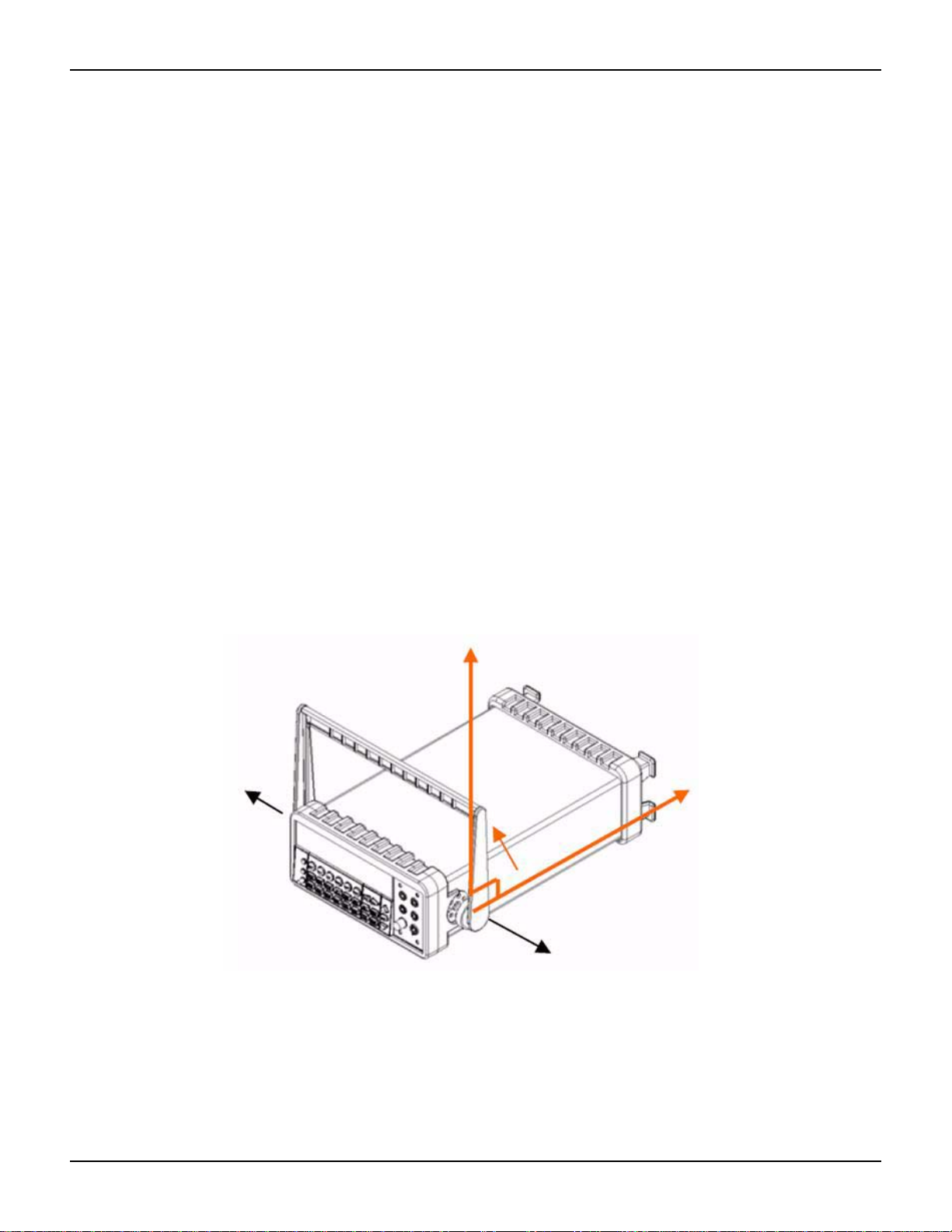
Adjusting the handle
You may adjust the carrying handle to suit your needs. Figures 2-1, 2-2, 2-3, 2-4, and 2-5 show
you how to adjust the handle.
Removing the handle
Step 1: Move the handle to an upright position.
Pull slightly outward on both sides of the handle, and slowly rotate it up as shown in Figure 2-1.
Figure 2-1
Moving the handle to an upright position
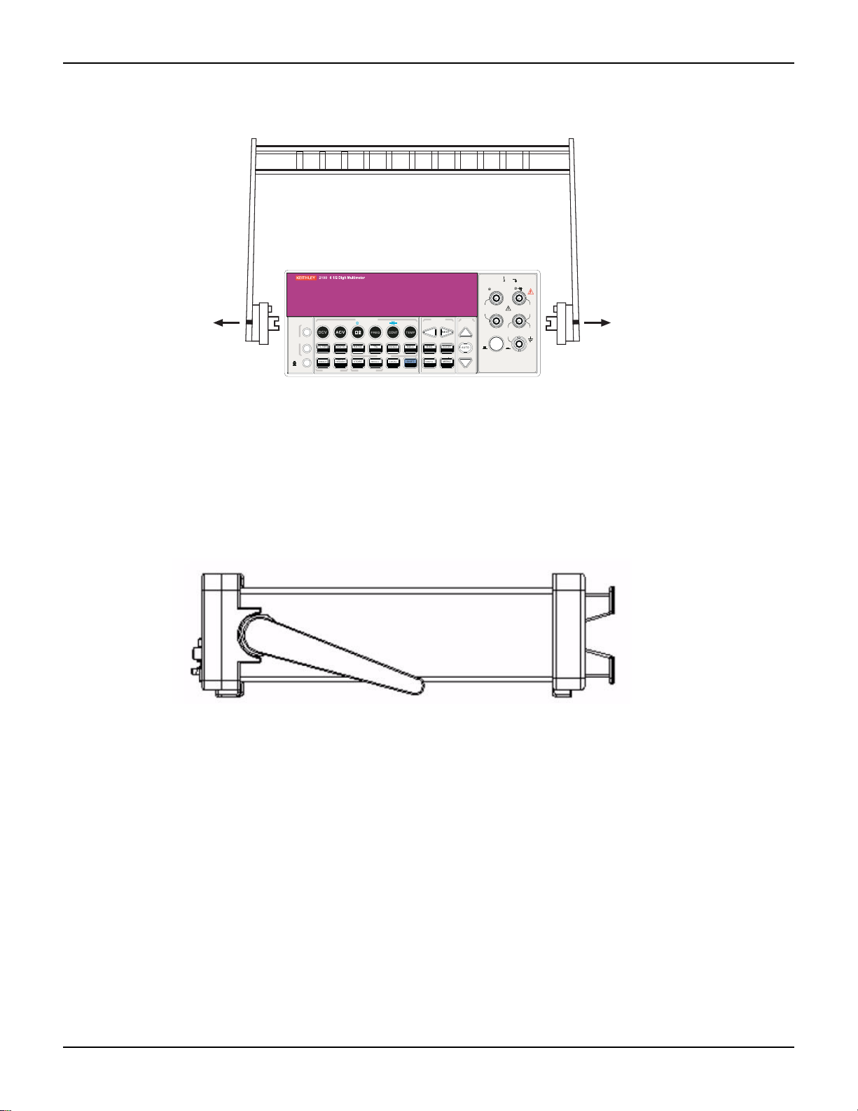
Step 2: Remove the handle
When the handle is turned up to a 90° angle with the multimeter, pull it away from the multimeter
(refer to Figure 2-2).
2-2 Return to Section Topics 2100-900-01 Rev. E / March 2012
Model 2100 6 1/2-Digit Resolution Digital Multimeter User’s Manual Section 2: Getting Started
FILTER
NEXT
PREV
DIGITS
RATIO
%
MIN/MAX
NULL
ESC
ENTER
AUTO
SINGLE
TRIGGER
STORE
RECALL
LOCAL
SHIFT
CONFIG
MENU
AUTO
DCV
ACV
22
FREQ
CONT
TEMP
4 WIRE
RATIO
V
INPUT
PEAK
200V
PEAK
HI
LO
PEAK
500V
3A
RMS
INPUTS
3A250V
FRONT/REAR
AMPS
R
1000V
REF
CAT 1000V
CAT 600V
LOCK
SETUP
ACV
22
FUNCTION
DCI ACI
4
PERIOD
LIMITS MX+B
dB
EXTRIG HOLD
MATH
TRIGGER MEMORY
dBm
RANGE
DISPLAY
NEXT
PREV
POWER
OFF
ON
SENSE
F
Figure 2-2
Removing the handle from the multimeter
Adjusting the handle position
You can adjust the Model 2100’s handle to suit your needs:
Position 1: Default
The default position is used for packing the Model 2100 (refer to Figure 2-3).
Figure 2-3
Default handle position
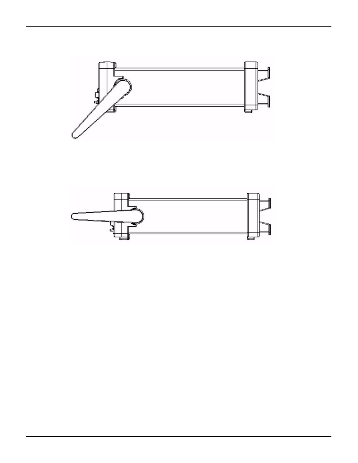
Position 2: Operating
The adjusted handle position shown in Figure 2-4 is for multimeter operation.
2100-900-01 Rev. E / March 2012 Return to Sect io n Topics 2-3
Section 2: Getting Started Model 2100 6 1/2-Digit Resolution Digital Multimeter User’s Manual
Figure 2-4
Operation handle position
Position 3: Carrying
The carrying position is shown in Figure 2-5.
Figure 2-5
Carrying position
Setting the line voltage
WARNING Before changing the setting, ensure that the multimeter is disconnected from
the AC power.
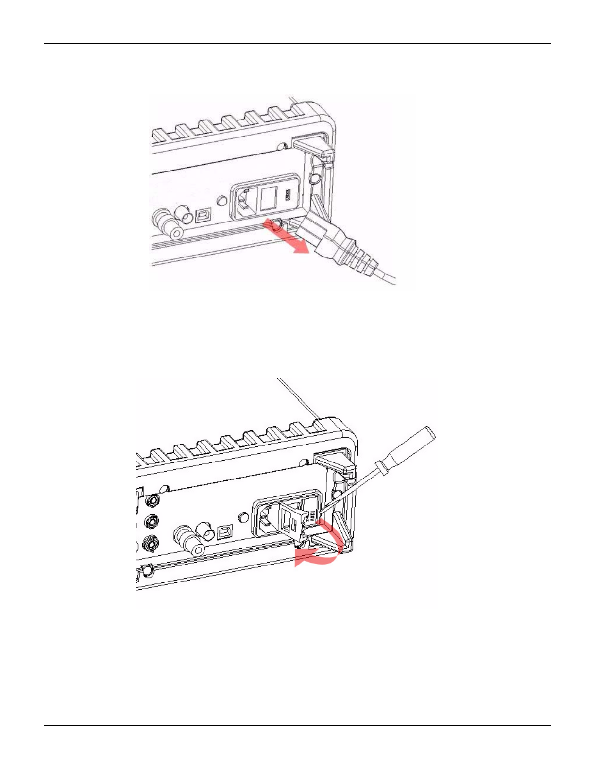
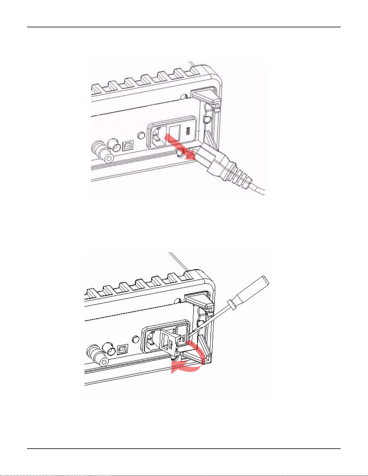
Step 1: Disconnect AC power
Verify that the meter is disconnected from AC power as shown in Figure 2-6.
2-4 Return to Section Topics 2100-900-01 Rev. E / March 2012
Model 2100 6 1/2-Digit Resolution Digital Multimeter User’s Manual Section 2: Getting Started
Figure 2-6
Disconnecting AC power
Step 2: Open the voltage setting selector
Open the voltage setting selector cap as shown in Figure 2-7 (a flat blade screwdriver may be
required).
Figure 2-7
Opening the voltage setting selector
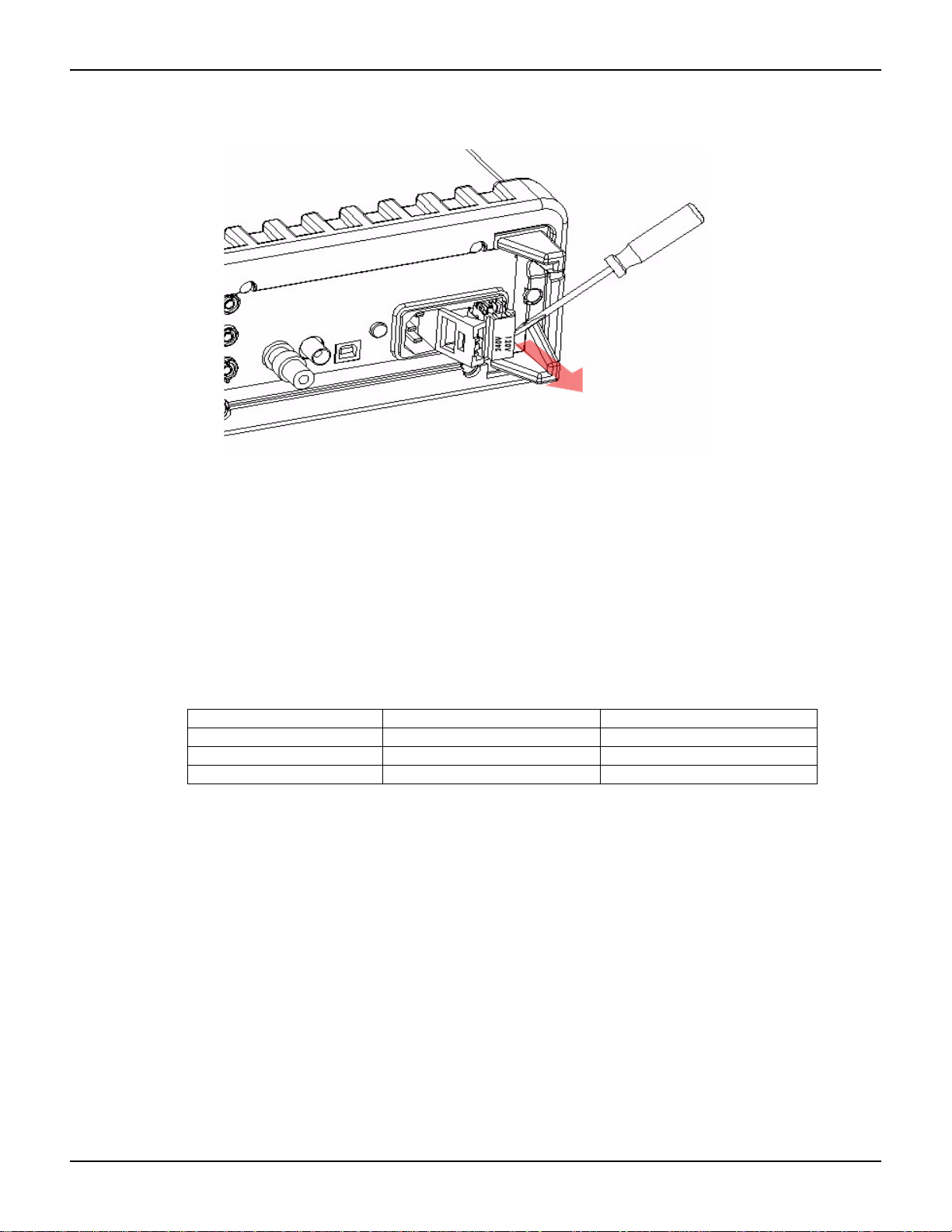
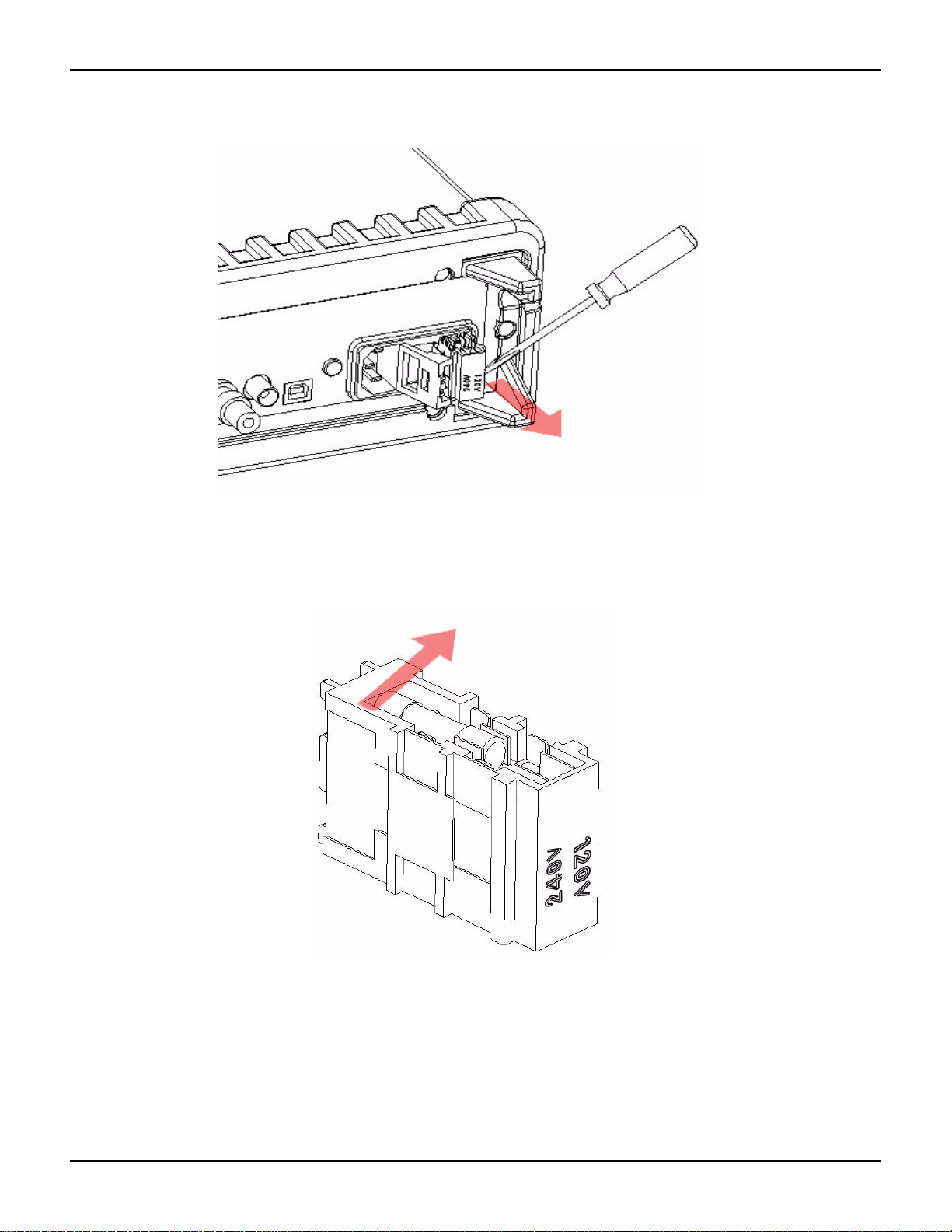
Step 3: Remove the red voltage setting selector
Remove the red voltage selector fuse holder from the righ t middle seam as shown in Fi gure 2-8 (a
flat blade screwdriver may be required).
2100-900-01 Rev. E / March 2012 Return to Sect io n Topics 2-5
Section 2: Getting Started Model 2100 6 1/2-Digit Resolution Digital Multimeter User’s Manual
Figure 2-8
Removing the red voltage selector fuse holder
Step 4: Change the voltage setting
Turn the voltage setting to the correct setting.
NOTE To accommodate differing local area power requ irement s, Keithl ey Instrument s has three
available models of voltage setting selectors for the Model 2100 (each with two voltage
settings). The voltage setting selector included with your Model 2100 should have the
appropriate voltage settings for your area's line power requirements. If you do not have
the correct voltage setting selector, please contact your local Keithley Instruments
representative to request the correct model (see Table 2-1, below).
Tab l e 2- 1
Available voltage setting selectors for local line power requirements
Model number Voltage select options Voltage set to:
2100/120 120/240 120
2100/230-240 120/240 240
2100/220 120/220 220
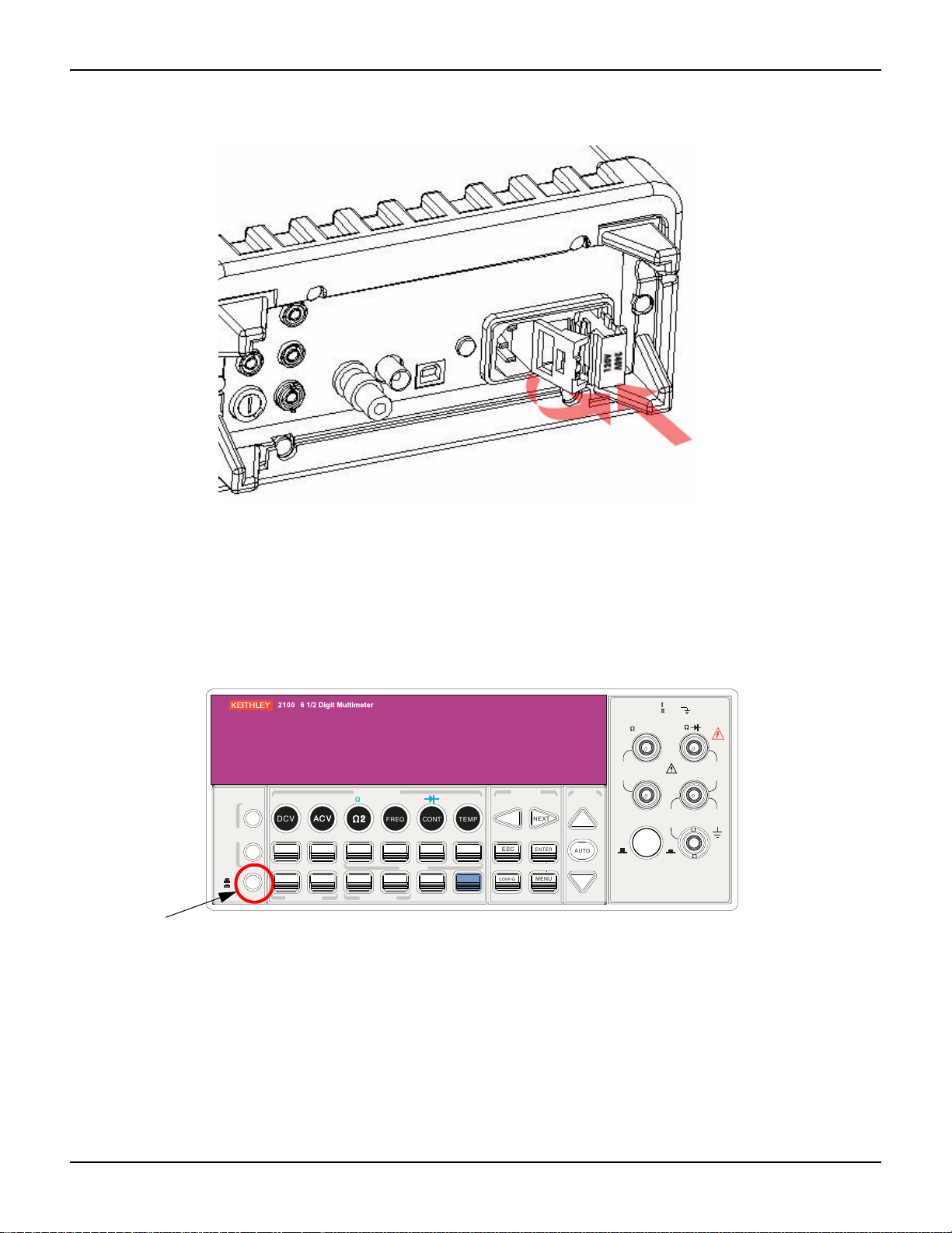
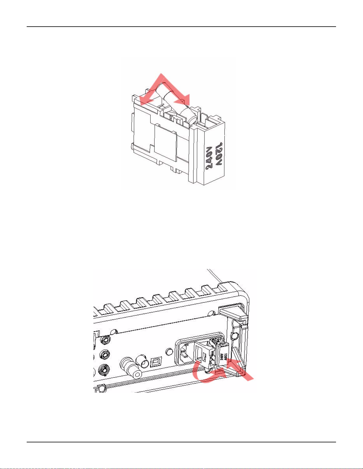
Step 5: Insert the voltage selector
Insert the voltage setting selector back into the socket and close the cap as shown in Figure 2-9.
2-6 Return to Section Topics 2100-900-01 Rev. E / March 2012
Model 2100 6 1/2-Digit Resolution Digital Multimeter User’s Manual Section 2: Getting Started
2
V
2
Figure 2-9
Inserting the voltage selector
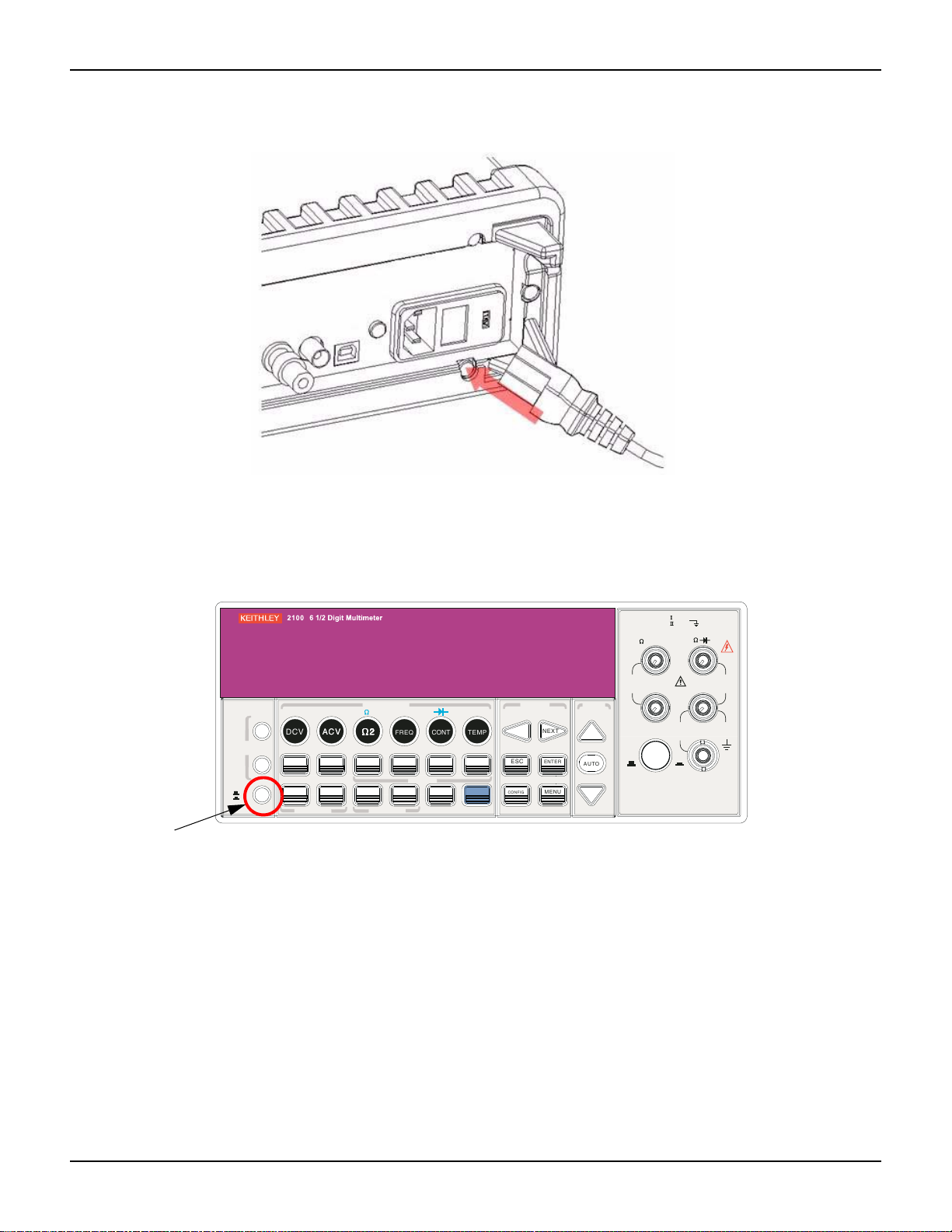
Connecting the power
Power-off the multimeter
Ensure that the power switch on the front panel is in the "POWER OFF" position before plugging
the Model 2100 in (refer to Figure 2-10).
Figure 2-10
Powering-off the multimeter
DCI ACI
PREV
DCV
ACV
DISPLAY
NEXT
OFF
ON
POWER
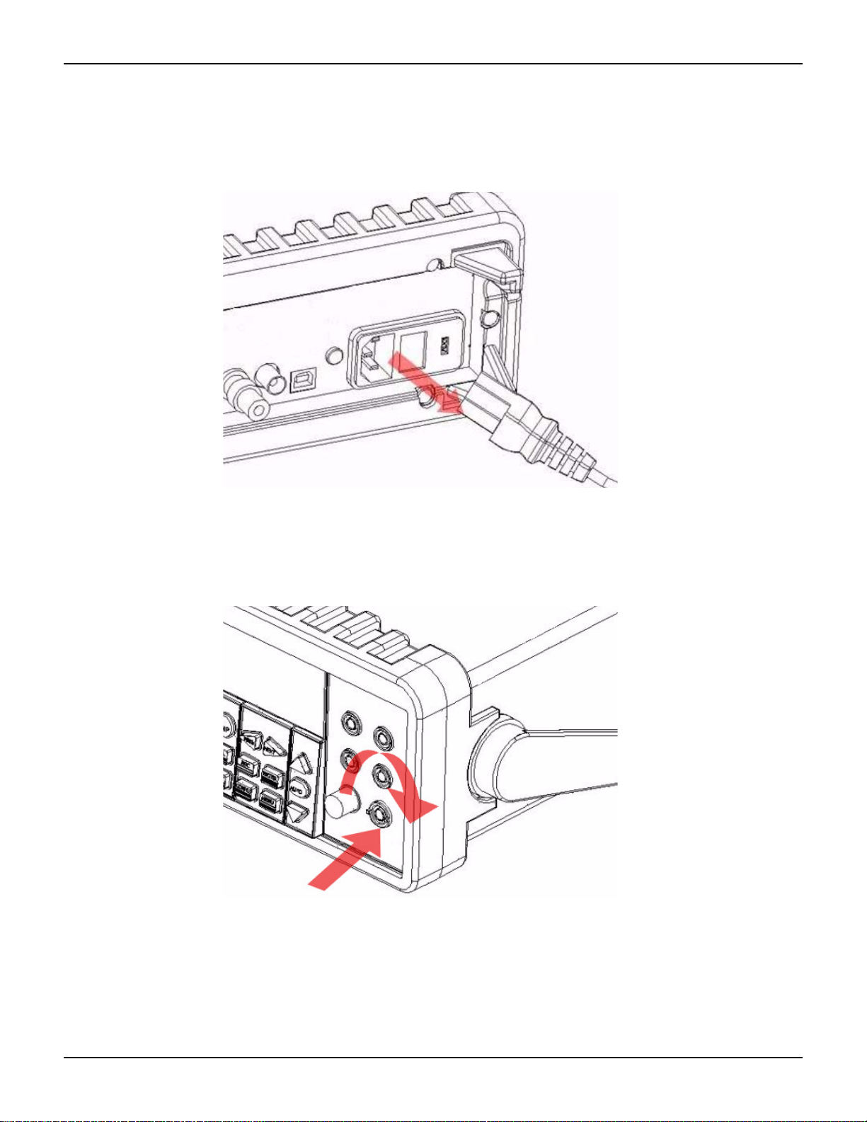
Plug-in the power cord
After finishing the above procedures, you can plug-in your power cord as shown in Figure 2-11.
ACV
FILTER
DIGITS
EXTRIG
HOLD
AUTO
SINGLE
TRIGGER
TRIGGER MEMORY
FUNCTION
4
PERIOD
2
2
FREQ
LIMITS MX+B
RATIO
%
RECALL
STORE
MATH
CONT
dBm
MIN/MAX
LOCAL
TEMP
dB
NULL
SHIFT
PREV
LOCK
ESC
CONFIG
SETUP
NEXT
ENTER
MENU
RANGE
AUTO
PEAK
200V
F
CAT 1000V
CAT 600V
SENSE
4 WIRE
RATIO
REF
INPUTS
FRONT/REAR
LO
RMS
INPUT
HI
1000V
PEAK
3A
500V
PEAK
R
3A 250V
AMPS
2100-900-01 Rev. E / March 2012 Return to Sect io n Topics 2-7
Section 2: Getting Started Model 2100 6 1/2-Digit Resolution Digital Multimeter User’s Manual
FILTER
NEXT
PREV
DIGITS
RATIO
%
MIN/MAX
NULL
ESC
ENTER
AUTO
SINGLE
TRIGGER
STORE
RECALL
LOCAL
SHIFT
CONFIG
MENU
AUTO
DCV
ACV
22
FREQ
CONT
TEMP
4 WIRE
RATIO
V
INPUT
PEAK
200V
PEAK
HI
LO
PEAK
500V
3A
RMS
INPUTS
3A 250V
FRONT/REAR
AMPS
R
1000V
REF
CAT 1000V
CAT 600V
LOCK
SETUP
ACV
22
FUNCTION
DCI ACI
4
PERIOD
LIMITS MX+B
dB
EXTRIG
HOLD
MATH
TRIGGER MEMORY
dBm
RANGE
DISPLAY
NEXT
PREV
POWER
OFF
ON
SENSE
F
Figure 2-11
Plugging in the power cord
Switch the power on
Press the power switch on the front panel to activate the Model 2100 as shown in Figure 2-12.
Figure 2-12
Switching on the power
Check the power-line voltage on the rear pa nel to see if the volt age setting is co rrect for your ar ea.
Change the setting if it is not correct by following the steps in “Setting the line voltage” later in this
section.
2-8 Return to Section Topics 2100-900-01 Rev. E / March 2012

Model 2100 6 1/2-Digit Resolution Digital Multimeter User’s Manual Section 2: Getting Started
WARNING Before connecting power to the Model 2100, ensure that the fuse is intact.
Refer to “Changing the fuses” later in this section if the fuse is open/blown.
WARNING The main power input voltage to the unit must be selecte d correctly accord ing
to the local installation’s power supply. Check the voltage indication window
on the power module at the back of the unit to verify the voltage setting is
correctly set. If the voltage is not correctly set, refer to “Setting the line
voltage” below.
WARNING The power cord supplied with the Model 2100 contains a separat e ground wire
for use with grounded outlets. When proper connections are made, the
instrument chassis is connected to power line ground through the ground
wire in the power cord. Failure to use a grounded outlet may r esult in personal
injury or death due to electric shock.
Changing the fuses
WARNING Before replacing the power-line fuse or current input fuses, verify that the
multimeter is disconnected from AC power. You must be qualified personnel
to perform this action.
CAUTION For continued protection against fire or instrument damage, only replace the
fuses with the same type and rating. If the instrument repe at edly blows fus es,
have the unit serviced at an authorized repair facility.
Power line fuse
A power-line fuse located next to the AC receptacle (in the voltage setting selector) protects the
power line input of the instrument. Verify that the power -line fuse is good an d replace it with a new
one if it is damaged. The Model 2100 is shipped from the factory with a 0.25A/250V, 5×20mm
slow-blow glass fuse installed (Keithley Instruments p art number FU-96-4) . This is the correct fuse
type for all line voltage settings; use only this type of replacement fuse.
T o change the power line fuse:
Step 1: Disconnect the AC power
Verify that the meter is disconnected from AC power as shown in Figure 2-13.
2100-900-01 Rev. E / March 2012 Return to Sect io n Topics 2-9
Section 2: Getting Started Model 2100 6 1/2-Digit Resolution Digital Multimeter User’s Manual
Figure 2-13
Disconnecting the AC power
Step 2: Open the voltage setting selector
Open the voltage setting selector cap as shown in Figure 2-14 (you will need a screwdriver to do
so).
Figure 2-14
Opening the voltage setting selector
Step 3: Remove the red voltage setting selector
Remove the red voltage setting selector from the right middle seam as shown in Figure 2-15 (you
might need a screwdriver to do so).
2-10 Return to Section Topics 2100-900-01 Rev. E / March 2012
Model 2100 6 1/2-Digit Resolution Digital Multimeter User’s Manual Section 2: Getting Started
Figure 2-15
Removing the red voltage setting selector
Step 4: Remove the damaged power line fuse
Remove the damaged fuse from the selector as shown in Figure 2-16.
Figure 2-16
Removing the damaged power line fuse
Step 5: Replace the power line fuse
Replace with the new fuse as shown in Figure 2-17.
2100-900-01 Rev. E / March 2012 Return to Sect io n Topics 2-11
Section 2: Getting Started Model 2100 6 1/2-Digit Resolution Digital Multimeter User’s Manual
Figure 2-17
Replacing the fuse
Step 6: Reinsert the voltage selector
Insert the voltage setting selector back into the socket and close the cap as shown in Figur e 2-18.
CAUTION Verify that the correct voltage setting appears in the red voltage selection
window in the power module before powering up the unit. Refer to
“Connecting the power” earlier in this section for instructions on how to
correctly power up the unit.
Figure 2-18
Reinserting the voltage selector
2-12 Return to Section Topics 2100-900-01 Rev. E / March 2012
Model 2100 6 1/2-Digit Resolution Digital Multimeter User’s Manual Section 2: Getting Started
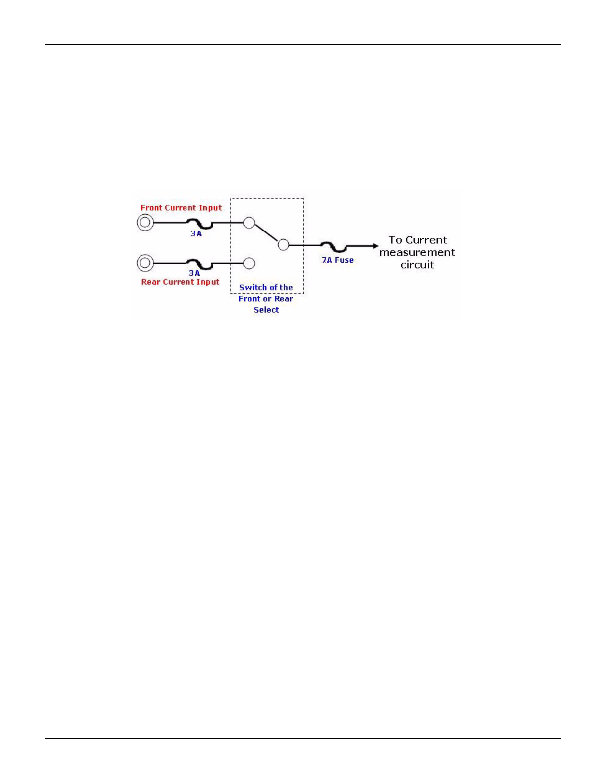
Current input fuses
The Model 2100 has two 3A fuses in the front and rear current input terminals, and an additional
7A fuse in series with either the front or rear current input fuse (depending on the front or rear
panel switch position) for added protection against a strong current pulse. If a strong current pulse
overloads the 7A fuse, it will blow quickly, thus saving the 3A fuse and the instrument's internal
circuitry (see Figure 2-19).
Figure 2-19
Current protection using 3A and 7A current input fuses in series
The two main fuses located in the front and rear current inp ut terminals of your Model 210 0 are 3A,
250V, 5x20mm fast-acting glass fuses (Keithley Instruments part number FU-99 -1). The additional
current input fuse is a 7A, 250V, 5x20mm fast-acting ceramic tube fuse. See the following text for
instructions on how to replace these fuses if they become damaged.
T o change the 3A front or rear p anel current input terminal fuses:
WARNING Before replacing the power line fuse or current input fuses, verify that the
multimeter is disconnected from AC power. You must be qualified personnel
to perform this procedure.
CAUTION For continued protection against fire or instrument damage, only replace the
fuses with the same type and rating. If the instrument repe at edly blows fus es,
have the unit serviced at an authorized repair facility.
NOTE Instructions for replacing the front panel current input terminal fuse are depicted here; the
rear panel current input terminal fuse can be changed using the same procedure.
2100-900-01 Rev. E / March 2012 Return to Sect io n Topics 2-13
Section 2: Getting Started Model 2100 6 1/2-Digit Resolution Digital Multimeter User’s Manual
Step 1: Disconnect the AC power
Verify that the meter is disconnected from AC power, as shown in Figure 2-20.
Figure 2-20
Disconnecting the AC power
Step 2: Release the current input terminal fuse holder
Push the current input terminal in and turn it to the right (see Figure 2-21) to rele as e it .
Figure 2-21
Releasing the current input terminal fuse holder
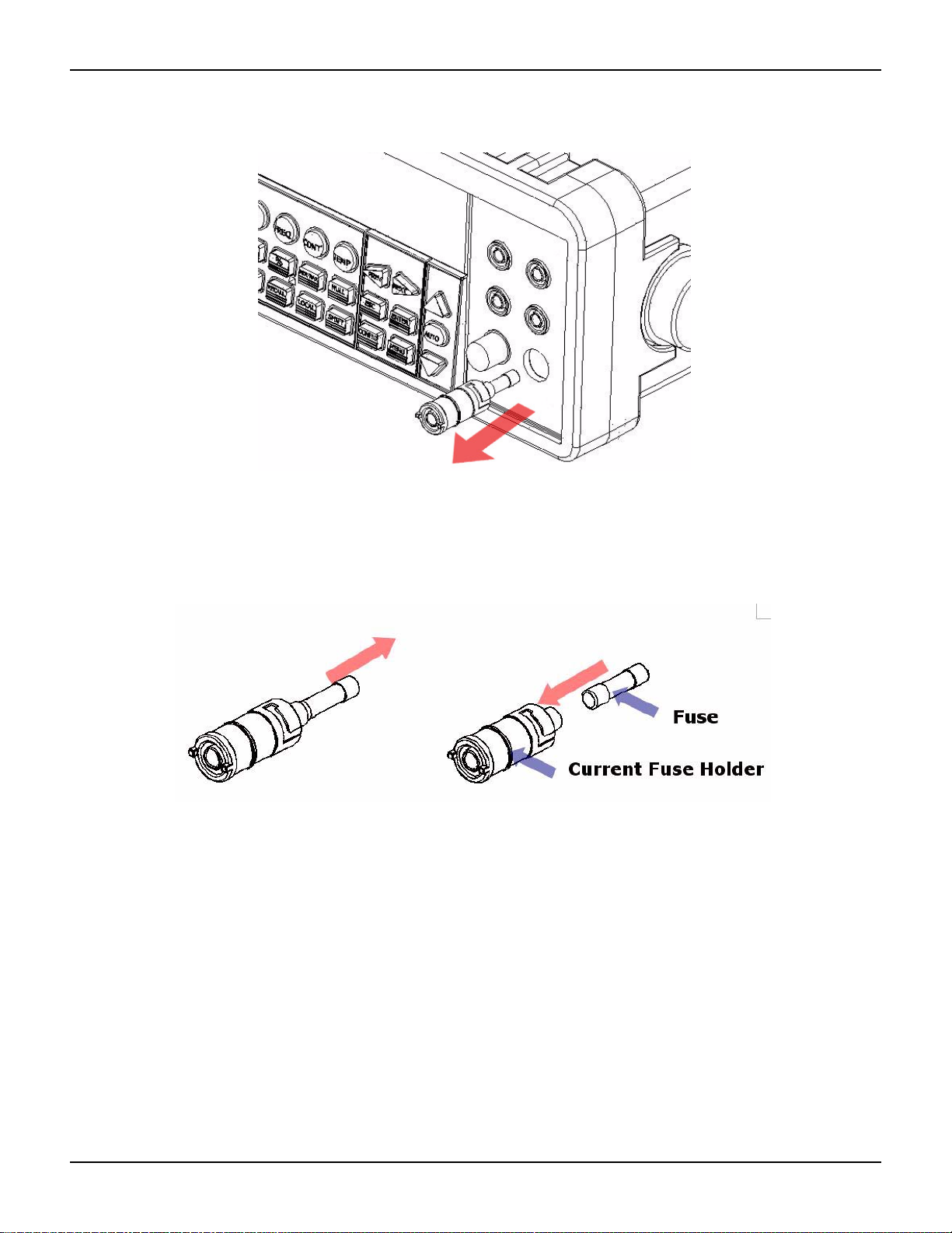
Step 3: Remove the current input terminal fuse holder
Gently pull out the current input terminal fuse holder to expose the current input fuse
(see Figure 2-22).
2-14 Return to Section Topics 2100-900-01 Rev. E / March 2012
Model 2100 6 1/2-Digit Resolution Digital Multimeter User’s Manual Section 2: Getting Started
Figure 2-22
Removing the current input terminal fuse holder
Step 4: Remove and replace the damaged fuse
Remove the damaged fuse and replace it with the same type and rating of fuse (see Figure 2-23).
Figure 2-23
Removing and replacing the damaged fuse
Step 5: Reinsert and secure the current input terminal fuse holder
Reinsert the current input terminal fuse holder, turning it to the left as you push it in
(see Figure 2-24). Ensure that the fuse holder is properly seated and secured.
2100-900-01 Rev. E / March 2012 Return to Sect io n Topics 2-15

Section 2: Getting Started Model 2100 6 1/2-Digit Resolution Digital Multimeter User’s Manual
Figure 2-24
Reinserting and securing the current input terminal fuse holder
WARNING Before reconnecting the power line cord to your multimeter, make sure that
the power switch is in the "POWER OFF" position.
T o change the 7A current input fuse on the rear p anel:
Step 1: Disconnect the AC power
Verify that the meter is disconnected from AC power, as shown in Figure 2-25.
Figure 2-25
Disconnecting the AC power
Step 2: Release the current input terminal fuse holder
Using a flat-blade screwdriver, turn the 7A current input fuse holder on the rear panel to the left
until it is released (see Figure 2-26).
2-16 Return to Section Topics 2100-900-01 Rev. E / March 2012

Model 2100 6 1/2-Digit Resolution Digital Multimeter User’s Manual Section 2: Getting Started
Figure 2-26
Releasing the 7A current input fuse holder on the rear panel
Step 3: Remove the current input terminal fuse holder
Gently pull out the current input terminal fuse holder to expose the 7A current input
fuse (see Figure 2-27).
Figure 2-27
Removing the 7A current input terminal fuse holder
Step 4: Remove and replace the damaged fuse
Remove the damaged fuse and replace it with the same type and rating of fuse (see Figure 2-28).
2100-900-01 Rev. E / March 2012 Return to Sect io n Topics 2-17

Section 2: Getting Started Model 2100 6 1/2-Digit Resolution Digital Multimeter User’s Manual
Figure 2-28
Removing and replacing the damaged fuse
Step 5: Reinsert and secure the 7A current input terminal fuse holder
Reinsert the 7A current input terminal fuse holder, turning it to the right as you push it in (see
Figure 2-29). Ensure that the fuse holder is properly seated and secur ed .
Figure 2-29
Reinserting and securing the 7A current input terminal fuse holder
WARNING Before reconnecting the power line cord to your multimeter, ensure that the
power switch is in the "POWER OFF" position.
Factory default settings
Table 2-2 shows the factory default settings for the Model 2100.
Table 2-2
Factory default
Function Default
Function DCV
Autozero On
Frequency and period source AC voltage
Output format ASCII
Ratio Off
AC bandwidth Input frequency 20Hz
2-18 Return to Section Topics 2100-900-01 Rev. E / March 2012

Model 2100 6 1/2-Digit Resolution Digital Multimeter User’s Manual Section 2: Getting Started
Table 2-2
Factory default
Function Default
Function DCV
Voltage AC digits 5.5
DC digits Slow 5.5 (1 PLC)
Range Auto
Current AC digits 5.5
DC digits slow 5.5 (1 PLC)
Range Auto
Frequency and period AC digits 5.5
Range Auto
Rate Medium (100ms)
Diode Test Digits 5.5
Range 1mA
Rate 0.1 PLC
Resistance (2-wire) Dig its Slow 5.5 (1 PLC)
Range Auto
Triggers Source Immediate
Delay Auto
Input Resistance 10MΩ
Model 2100 familiarization
The Model 2100 6 1/2-Digit Resolution Digital Multimeter consists of three major parts: the front
panel, the display, and the rear panel. Following is a discussion of these components.
The front panel
The keys and terminals on the front panel are divided into the following groups (refer to
Figure 2-30):
• DISPLAY and POWER
• FUNCTION, MATH, TRIGGER, MEMORY, SETUP, RANGE, and INPUT TERMINALS
• FILTER, DIGITS, LOCAL, and SHIFT
2100-900-01 Rev. E / March 2012 Return to Sect io n Topics 2-19

FILTER
NEXT
PREV
DIGITS
RATIO
%
MIN/MAX
NULL
ESC
ENTER
AUTO
SINGLE
TRIGGER
STORE
RECALL
LOCAL
SHIFT
CONFIG
MENU
AUTO
DCV
ACV
22
FREQ
CONT
TEMP
4 WIRE
RATIO
V
INPUT
PEAK
200V
PEAK
HI
LO
PEAK
500V
3A
RMS
INPUTS
3A 250V
FRONT/REAR
AMPS
R
1000V
REF
CAT 1000V
CAT 600V
LOCK
SETUP
ACV
22
FUNCTION
DCI ACI
4
PERIOD
LIMITS MX+B
dB
EXTRIG
HOLD
MATH
TRIGGER MEMORY
dBm
RANGE
DISPLAY
NEXT
PREV
POWER
OFF
ON
SENSE
F
1
5432
Section 2: Getting Started Model 2100 6 1/2-Digit Resolution Digital Multimeter User’s Manual
Figure 2-30
Front panel keys and terminals
1. DISPLAY and POWER keys:
i. DISPLAY: Shows model, version and condition by pressing the PREV and NEXT
keys
ii. POWER: Activates the Model 2100 digital multimeter
2. FUNCTION keys:
a. First row without SHIFT key:
i. DCV: Selects DC voltage measurement
ii. ACV: Selects AC voltage measurement
iii. Ω 2: Selects 2-wire resistance measurement
iv. FREQ: Selects frequency measurement
v. CONT: Selects the continuity test
b. First row with SHIFT key:
i. DCI: Selects DC current measurement
ii. ACI: Selects AC current measurement
iii. Ω 4: Selects 4-wire resistance measurement
iv. PERIOD: Selects period measurement
v. : Selects diode testing
c. Second row without SHIFT key:
i. FILTER: Enables or disables the digital filter
ii. DIGITS: Changes the resolution
iii. RATIO: Enables the dcv:dcv ratio function
iv. %: Calculates the ratio to a target value in percentage
v. MIN/MAX: Captures the minimum or maximum readings from the measurement
vi. NULL: Activates the offset function in order to get the real measured reading
d. Second row with SHIFT key:
i. LIMITS: Used for setting upper and lower limit values for readings
ii. MX+B: Used for calculating slope. X is the normal display reading; M and B are
iii. dBm: Used for displaying voltage measurement in dBm power unit
iv. dB
e. Third row without SHIFT key:
2-20 Return to Section Topics 2100-900-01 Rev. E / March 2012
constants specified by user for scale factor and offset
: Used for displaying voltage measurement in decibel unit

Model 2100 6 1/2-Digit Resolution Digital Multimeter User’s Manual Section 2: Getting Started
i. SINGLE: Manually triggers the multimeter to make measurements
ii. AUTO TRIGGER: Instructs the multimeter to make measurements continuously
iii. STORE: Stores a specified number of subsequent readings
iv. RECALL: Displays stored readings. Use the left and right
arrow keys or the up and down arrow keys to toggle between reading numbe r and
reading
v. LOCAL: Cancels USB remote mode
vi. SHIFT (in blue): Used to select functions that appear on keys in blue uppercase
text
f. Third row with SHIFT key:
i. EXTRIG: Selects external triggers as the trigger source via BNC port on the rear
panel
ii. HOLD: Holds a reading
3. SETUP keys:
a. First row in SETUP section:
i. : Scrolls through the buffer, conceals or reveals the digits while measuring
b. Second row in SETUP section:
i. ESC: Cancels selection, moving back to the measurement display
ii. ENTER: Accepts selection, moving to next choice or back to the measurement
display
iii. LOCK: Press SHIFT then ESC key to prevent unpredictable operation on the
panel; to release the lock condition, press ESC again
c. Third row in SETUP section:
i. CONFIG: Allows setting or adjustment functions relating to some front panel keys
ii. MENU: Allows setting or adjustment functions not relating to other front panel
keys
4. RANGE keys:
i. : Moves to higher range
ii. : Moves to lower range
iii. AUTO: Enables or disables auto-range
5. INPUTS (TERMINALS) toggle button, FUSE device connection, an d inserted connections:
i. : TERMINALS toggle button: Selects input signal
connections on front or rear panel
ii. Input HI and LO: Used for DCV, ACV, O2, CONT, FREQ, PERIOD, and RTD
temperature measurements
AMPS: Used with INPUT LO for DCI and ACI measurements; also
holds current fuse for front panel amps input
SENSE HI and LO:
measurements
iii. LO and I: Used for making DC and AC current measurements
iv. Front FUSE: Secures your meter against damage by strong current pulses
(maximum current: 3A, 250V)
Used with INPUT HI and LO for O4 and RTD temperature
The display
The Model 2100 has a 5x7 character dot-matrix, dual-line display with three-color (white, red, and
yellow) annunciators for easy viewing. There are two rows in the dual-display screen. The upper
row displays both readings and measurement units. A maximum of 13 characters is possible for
the upper row dot-matrix display. The lower row displays the range of the measurements and
conditions, or information about the current configuration. A maximum of 16 characters is possible
2100-900-01 Rev. E / March 2012 Return to Sect io n Topics 2-21

Section 2: Getting Started Model 2100 6 1/2-Digit Resolution Digital Multimeter User’s Manual
for the lower row dot-matrix display. There are additional annunciators above and on the right side
of the display screen that indicate the state or condition of an ongoing measurement. They are
explained individually in the following sections.
Figure 2-31
The display
Annunciators at the top
Figure 2-32
Annunciators at the top
• RMT (REMOTE): Indicates the remote state (USB Interface)
• MAN: Indicates the manual range mode is selected
• TRIG: Shows that single triggering is enabled
• HOLD: Indicates reading hold function is enabled
• MEM: Indicates the use of internal reading memory
• RATIO: Indicates the dcv:dcv ratio operation
• MATH: Indicates the MATH operation is enabled
• ERR: Error occurred
• SHIFT: Indicates the SHIFT button was pressed
• REAR: The rear panel input terminal is selected for the measurement
• FILT: The digital filter is enabled
• 4W: Indicates remote sense
• EXT: Indicates external trigger
2-22 Return to Section Topics 2100-900-01 Rev. E / March 2012

Model 2100 6 1/2-Digit Resolution Digital Multimeter User’s Manual Section 2: Getting Started
LIN E
120V
240V
2
4
0V
Annunciators on the right
• 4W: Indicates 4-wire mode is selected for resistance measurement
• : Indicates that continuity testing is enabled
• : Indicates the diode testing operation was initiated
• EXT: Indicates the External Trigger mode is been enabled
• LOCK: Indicates the front panel menu operation is locked
• OFF: Indicates the front panel display is turned off
Figure 2-33
Annunciators on the right
The rear panel
The rear panel of the Model 2100 is shown in Figure 2-34. This figure includes important
abbreviated information that should be reviewed before using the instrument.
Figure 2-34
The rear panel
1
CAT 1000V
CAT 600V
*T w0 00 01 00 0*
MADE IN
TAIWA N
WARNI NG
NO INTERNAL SERVICEABLE PARTS, SERVICE
BY QUAL IFIED PERSONNEL ONLY.
CAUTION:
FOR CONTINUED PROTECTION AGAINST FIRE HAZARD.
REPLACE FUSE WITH SAME TYPE AND RATING.
120V
240V
24
0V
432
1. Inserted connections and fuse devices:
a. Input HI and LO: Used for DCV, ACV, O2, CONT, FREQ, PERIOD, and RTD
temperature measurements
AMPS: Used with INPUT LO for DCI and ACI measurements; also
holds current fuse for front panel amps input
SENSE HI and LO: Use with INPUT HI and LO for O4 and RTD temperature
measurements
b. LO and I: Used for making AC and DC current measurements
c. Rear fuse: Secures the meter against damage by strong current pulses
2. USB connection:
a. Connects a remote computer to operate the meter (instead of the front panel control)
3. Chassis ground terminal
4. Power module:
2100-900-01 Rev. E / March 2012 Return to Sect io n Topics 2-23

Section 2: Getting Started Model 2100 6 1/2-Digit Resolution Digital Multimeter User’s Manual
a. Contains the AC line receptacle, power line fuse, and line voltage setting
• Configured for line voltages of 120/220V or 120/240V (depending on the power
utility in your area)
2-24 Return to Section Topics 2100-900-01 Rev. E / March 2012

In this section:
Topic Page
Introduction ......................................................................................... 3-2
Voltage measurements (DC and AC).................................................. 3-2
Current measurements (DC and AC).................................................. 3-3
Resistance measurements (2- and 4-wire)......................................... 3-4
Frequency and period measurements ................................................ 3-6
Continuity measurements ................................................................... 3-7
Diode measurements.......................................................................... 3-7
RTD measurements............................................................................ 3-8
Section 3
Basic Measurement Functions
How to measure voltage............................................................... 3-3
How to measure current ............................................................... 3-3
How to measure resistance.......................................................... 3-6
How to measure frequency and period......................................... 3-6
How to measure the continuity ..................................................... 3-7
How to measure a diode............................................................... 3-8
2-wire RTD measurements........................................................... 3-8
3-wire RTD measurements........................................................... 3-9
4-wire RTD measurements........................................................... 3-10

Section 3: Basic Measurement Functions Model 2100 6 1/2-Digit Resolution Digital Multimeter User’s Manual
FILTER
NEXT
PREV
DIGITS
RATIO
%
MIN/MAX
NULL
ESC
ENTER
AUTO
SINGLE
TRIGGER
STORE
RECALL
LOCAL
SHIFT
CONFIG
MENU
AUTO
DCV
ACV
22
FREQ
CONT
TEMP
4 WIRE
RATIO
V
INPUT
PEAK
200V
PEAK
HI
LO
PEAK
500V
3A
RMS
INPUTS
3A 250V
FRONT/REAR
AMPS
R
1000V
REF
CAT 1000V
CAT 600V
LOCK
SETUP
ACV
22
FUNCTION
DCI ACI
4
PERIOD
LIMITS MX+B
dB
EXTRIG
HOLD
MATH
TRIGGER MEMORY
dBm
RANGE
DISPLAY
NEXT
PREV
POWER
OFF
ON
SENSE
F
CONFIG
3
2
1
DCV
4
AUTO
5
6
DC voltage
source
Input resistance = 10MΩ on 1000V and 100V ranges:
> 10GΩ on 10V, 1V, and 100mV ranges.
2
V
2
CONFIG
ACVACV
AUTO
Introduction
This section introduces some basic measurement functions of the Keithley Instruments Model
2100 6 1/2-Digit Resolution Digital Multimeter
multimeter to measure voltage, current, resistance, frequency, period, continuity, and diode
forward voltage.
V olt age measurements (DC and AC)
The ranges for DC voltage (DCV) measurements for the Model 2100 are 100mV, 1V, 10V, 100V,
and 1000V. For AC voltage (ACV) measurements, the ranges are 100mV to 75 0V RMS, or 10 00V
peak. Figures 3-1 and 3-2 show the locations of the keys needed and message displays for
voltage measurement. Figure 3-3 shows the location of the input terminals on the rear panel.
WARNING Do not apply more than 1000V (peak) to the Model 2100 multimeter. Applying
excess voltage may damage your meter or cause possible electric shock,
resulting in personal injury or death.
NOTE To eliminate the thermal EMFs due to the differences between two metals, use copper
leads to connect your source signal to the meter.
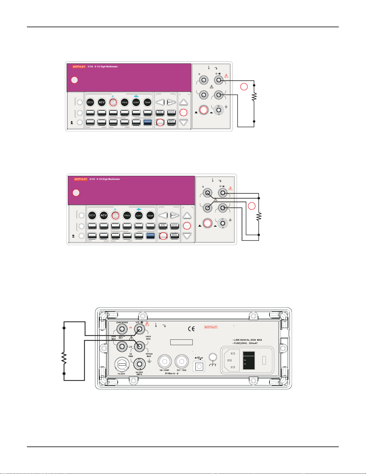
Figure 3-1
Model 2100 DC connections
®
. You will learn how to use the Model 2100
Figure 3-2
Model 2100 AC connections
6
DCI ACI
PREV
DCV
ACV
ACV
DISPLAY
NEXT
OFF
ON
POWER
3-2 Return to Section Topics 2100-900-01 Rev. E / March 2012
Input Impedence = 1MΩ in parallel with < 100pF
(Warning: Maximum input = 750V RMS, 1000V peak, 8x10’ V-Hz)
4
DIGITS
FILTER
EXTRIG
HOLD
AUTO
SINGLE
TRIGGER
TRIGGER MEMORY
FUNCTION
4
2
2
LIMITS MX+B
RATIO
STORE
PERIOD
FREQ
%
RECALL
MATH
CONT
dBm
MIN/MAX
LOCAL
TEMP
dB
NULL
SHIFT
LOCK
CONFIG
PREV
ESC
3
SETUP
NEXT
ENTER
MENU
RANGE
AUTO
5
CAT 1000V
CAT 600V
INPUT
SENSE
4 WIRE
HI
RATIO
200V
REF
PEAK
INPUTS
F
1
FRONT/REAR
1000V
PEAK
LO
3A
RMS
R
3A250V
AMPS
2
AC voltage
source
500V
PEAK

Model 2100 6 1/2-Digit Resolution Digital Multimeter User’s Manual Section 3: Basic Measurement Functions
AC
VM
CAT 1000V
CAT 600V
LINE
120V120V
240V240V
24
0V240V
*T w0 00 01 00 0*
MADE IN
TAIWA N
NO INTERNAL SERVICEABLE PARTS, SERVICE
WARNING
BY QUAL IFIED PERSONNEL ONLY.
FOR CONTINUED PROTECTION AGAINST FIRE HAZARD.
CAUTION:
REPLACEFUSEWITHSAMETYPEANDRATING.
DC
VM
or
VM = Voltage measurement
Figure 3-3
Model 2100 rear panel input terminals
NOTE Follow the same procedure when using either the front or rear panel terminals (refer to
Figure 3-3).
How to measure voltage
1. Select input signal connections on front or rear panel.
2. Connect the test leads to the terminals as shown in Figure 3-1 (DC) or Figure 3-2 (AC).
3. Set the resolution of DCV (refer to “Resolution setting (digits)” in Section 4), bandwidth of
ACV (refer to “AC filter” in Section 4) or skip this step if the default settings are used.
4. Press the DCV or ACV key for DC or AC voltage measurement.
5. Select the auto-range function by pressing the AUTO key on the front panel, or use the up
and down arrow keys to select the desired range.
6. Connect the test leads to your source signal and observe th e reading shown on the display.
If the input signal is beyond the allowed range, an overflow message ("OVLD") will be
displayed.
Current measurements (DC and AC)
The ranges for DC current measurements for the Model 2100 are 1 0mA, 100mA, 1A, and 3A, with
a sensitivity of 10NA. For AC current measurements, the range is 1A to 3A RMS with a sensitivity
of 10
μA. Figures 3-4 and 3-5 illustrate how to measure DC/AC currents with the Model 2100.
CAUTION The maximum input current allowed is 3A, 250V. Do not apply excess current
to your meter to avoid damaging the fuse of current input.
How to measure current
1. Select input signal connections on front or rear panel.
2. Connect the test leads to the terminals as shown in Figure 3-4.
3. Set the resolution of DCI (refer to “Resolution setting (digits)” in Section 4), and bandwidth
of ACI (refer to “AC filter” in Section 4), or skip this step if the default setting is used.
4. Press SHIFT + DCV or SHIFT + ACV keys for DCI or ACI measurement.
5. Select the auto-range function by pressing the AUTO key on the front panel, or use the up
6. Connect test leads to your source signal and observe the reading shown on the display. If
and down arrow keys to select the desired range.
the input signal is greater than the allowed range, an overflow message ("OVLD") will be
displayed.
2100-900-01 Rev. E / March 2012 Return to Sect io n Topics 3-3

Section 3: Basic Measurement Functions Model 2100 6 1/2-Digit Resolution Digital Multimeter User’s Manual
FILTER
NEXT
PREV
DIGITS
RATIO
%
MIN/MAX
NULL
ESC
ENTER
AUTO
SINGLE
TRIGGER
STORE
RECALL
LOCAL
SHIFT
CONFIG
MENU
AUTO
DCV
ACV
22
FREQ
CONT
TEMP
4 WIRE
RATIO
V
INPUT
PEAK
200V
PEAK
HI
LO
PEAK
500V
3A
RMS
INPUTS
3A250V
FRONT/REAR
AMPS
R
1000V
REF
CAT 1000V
CAT 600V
LOCK
SETUP
ACV
22
FUNCTION
DCI ACI
4
PERIOD
LIMITS MX+B
dB
EXTRIG
HOLD
MATH
TRIGGER MEMORY
dBm
RANGE
DISPLAY
NEXT
PREV
POWER
OFF
ON
SENSE
F
CONFIG
3
2
1
DCV
4
AUTO
5
6
Current
source
(Warning: Maximum input = 3A DC or RMS)
SHIFT
1
CM
CAT 1000V
CAT 600V
LIN E
120V120V
240V240V
24
0V240V
*T w0 00 01 00 0*
MADE IN
TAIWA N
NO INTERNAL SERVICEABLE PARTS, SERVICE
WARNING
BY QUAL IFIED PERSONNEL ONLY.
FOR CONTINUED PROTECTION AGAINST FIRE HAZARD.
CAUTION:
REPLACEFUSEWITHSAMETYPEANDRATING.
CM = Current measurement
Figure 3-4
Model 2100 current measurement (front panel)
NOTE Follow the same procedure when using either the front or rear panel terminals (refer to
Figure 3-5).
Figure 3-5
Model 2100 current measurement
Resistance measurement s (2- and 4-wire)
The ranges for resistance measurement are 100Ω, 1KΩ , 10kΩ , 100kΩ , 1MΩ , 10MΩ , and
100MΩ , with a sensitivity of 100
resistance:
2-wire mode (refer to Figure 3-6) and 4-wire mode (refer to Figure 3-7). In 4-wire mode, the test
current is sourced to the test resistance thr oug h one pair of test leads, and the test voltage across
the resistance under test is measured from another set of test leads. As a result, the 4-wire mode
is more accurate for low resistance measurements. The disadvantage of this is the longer settling
time for 4-wire mode. Figures 3-8 and 3-9 show the input terminal connections on the rear panel
for 2-wire mode and 4-wire mode respectively.
3-4 Return to Section Topics 2100-900-01 Rev. E / March 2012
μΩ (on 100Ω range). There are two modes for measuring the
Model 2100 6 1/2-Digit Resolution Digital Multimeter User’s Manual Section 3: Basic Measurement Functions
FILTER
NEXT
PREV
DIGITS
RATIO
%
MIN/MAX
NULL
ESC
ENTER
AUTO
SINGLE
TRIGGER
STORE
RECALL
LOCAL
SHIFT
CONFIG
MENU
AUTO
DCV
ACV
22
FREQ
CONT
TEMP
4 WIRE
RATIO
V
INPUT
PEAK
200V
PEAK
HI
LO
PEAK
500V
3A
RMS
INPUTS
3A250V
FRONT/REAR
AMPS
R
1000V
REF
CAT 1000V
CAT 600V
LOCK
SETUP
ACV
22
FUNCTION
DCI ACI
4
PERIOD
LIMITS MX+B
dB
EXTRIG
HOLD
MATH
TRIGGER MEMORY
dBm
RANGE
DISPLAY
NEXT
PREV
POWER
OFF
ON
SENSE
F
CONFIG
3
2
1
2222
4
AUTO
5
6
Ω2 resistance
under test
Note: Source current flows from the INPUT HI to
INPUT LO terminals.
FILTER
NEXT
PREV
DIGITS
RATIO
%
MIN/MAX
NULL
ESC
ENTER
AUTO
SINGLE
TRIGGER
STORE
RECALL
LOCAL
SHIFT
CONFIG
MENU
AUTO
DCV
ACV
22
FREQ
CONT
TEMP
4 WIRE
RATIO
V
INPUT
PEAK
200V
PEAK
HI
LO
PEAK
500V
3A
RMS
INPUTS
3A250V
FRONT/REAR
AMPS
R
1000V
REF
CAT 1000V
CAT 600V
LOCK
SETUP
ACV
22
FUNCTION
DCI ACI
4
PERIOD
LIMITS MX+B
dB
EXTRIG
HOLD
MATH
TRIGGER MEMORY
dBm
RANGE
DISPLAY
NEXT
PREV
POWER
OFF
ON
SENSE
F
CONFIG
3
2
1
2222
4
AUTO
5
6
Ω4 resistance
under test
Note: Source current flows from the INPUT HI to
INPUT LO terminals.
CAT 1000V
CAT 600V
LIN E
120V120V
240V240V
24
0V240V
*T w0 00 01 00 0*
MADE IN
TAIWA N
NO INTERNAL SERVICEABLE PARTS, SERVICE
WARNING
BY QUAL IFIED PERSONNEL ONLY.
FOR CONTINUED PROTECTION AGAINST FIRE HA ZARD.
CAUTION:
REPLACEFUSEWITHSAMETYPEANDRATING.
Figure 3-6
Model 2100 2-wire resistance
Figure 3-7
Model 2100 4-wire resistance
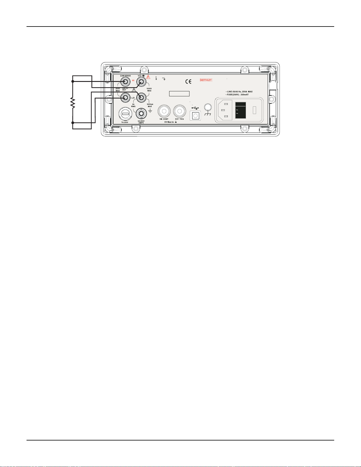
NOTE Follow the same procedure when using either the front or rear panel terminals as shown
Figure 3-8
Model 2100 rear panel 2-wire resistance measurement
2100-900-01 Rev. E / March 2012 Return to Sect io n Topics 3-5
in Figures 3-8 and 3-9.
Section 3: Basic Measurement Functions Model 2100 6 1/2-Digit Resolution Digital Multimeter User’s Manual
CAT 1000V
CAT 600V
LINE
120V120V
240V240V
24
0V240V
*T w0 00 01 00 0*
MADE IN
TAIWA N
NO INTERNAL SERVICEABLE PARTS, SERVICE
WARNING
BY QUAL IFIED PERSONNEL ONLY.
FOR CONTINUED PROTECTION AGAINST FIRE HAZARD.
CAUTION:
REPLACEFUSEWITHSAMETYPEANDRATING.
Figure 3-9
Model 2100 rear panel 4-wire resistance measurement
How to measure resistance
1. Select input signal connections on front or rear panel.
2. Connect the test leads to the terminals as shown in Figure 3-6 (2-wire) or Figure 3-7
(4-wire).
3. Set the resolution (refer to “Resolution setting (digits)” in Section 4), or skip this step if the
default setting is used.
4. Press Ω 2 key for a 2-wire measurement or SHIFT + Ω 2 keys for 4-wire measurement.
5. Select the auto-range function by pressing the AUTO key on the front panel, or use the up
and down arrow keys to select the desired range.
6. Connect test leads to your source signal and observe the reading shown on the display. If
the input signal is greater than the allowed range, an overflow message ("OVLD") will be
displayed.
Frequency and period measurements
The Model 2100 uses an on-board counter with 25MHz to measure the frequency (per iod). The
measurement band is from 3Hz to 300kHz (or 333ms to 3.3
range from 100mV to 750V in AC. The default setting for RANGE is “auto-range.”
WARNING The maximum input voltage allowed is 1000V. Applying excess voltage may
damage the meter and cause unpredictable hazards that may result in
personal injury or death.
How to measure frequency and period
1. Select input signal connections on front or rear panel.
2. Connect the test leads to the terminals as shown in Figure 3-2.
3. Set the resolution (refer to “Set ADC (Auto Zero and Auto Gain)” in Section 4) and input
4. Press the FREQ button for frequency measurement or the SHIFT + FREQ keys for period
5. Select the AUTO-RANGE function by pressing the AUTO key on the front panel, or use the
3-6 Return to Section Topics 2100-900-01 Rev. E / March 2012
jack, or skip this step if the default setting is used.
measurement.
up and down arrow keys to select the desired range.
μs), and the measurement voltages

Model 2100 6 1/2-Digit Resolution Digital Multimeter User’s Manual Section 3: Basic Measurement Functions
FILTER
NEXT
PREV
DIGITS
RATIO
%
MIN/MAX
NULL
ESC
ENTER
AUTO
SINGLE
TRIGGER
STORE
RECALL
LOCAL
SHIFT
CONFIG
MENU
AUTO
DCV
ACV
22
FREQ
CONT
TEMP
4 WIRE
RATIO
V
INPUT
PEAK
200V
PEAK
HI
LO
PEAK
500V
3A
RMS
INPUTS
3A 250V
FRONT/REAR
AMPS
R
1000V
REF
CAT 1000V
CAT 600V
LOCK
SETUP
ACV
22
FUNCTION
DCI ACI
4
PERIOD
LIMITS MX+B
dB
EXTRIG
HOLD
MATH
TRIGGER MEMORY
dBm
RANGE
DISPLAY
NEXT
PREV
POWER
OFF
ON
SENSE
F
CONFIG
3
2
1
CONT
4
5
Ω2 resistance
under test
Note: Source current flows from the INPUT HI to
INPUT LO terminals.
6. Connect test leads to your source signal and observe the reading shown on the display. If
the input signal is beyond the allowed range, an overflow message ("OVLD") will be
displayed.
NOTE Follow the same procedure when using either the front or rear panel terminals (refer to
Figure 3-3).
Continuity measurements
The Model 2100 uses 1KΩ range for the continuity measurement. The meter beeps when the test
resistance is less than the threshold resistance. The default threshold resistance is 10Ω , but you
can set the threshold resistance to anything between 1Ω and 1KΩ. The resistance value you set
is stored in volatile memory and will be cleared after the me ter has been turned off. The source
current for the continuity measurement is 1mA.
WARNING The maximum input voltage allowed is 1000V. Applying excess voltage may
damage the meter and cause unpredictable hazards that may result in
personal injury or death.
How to measure the continuity
Select input signal connections on the front or rear panel.
1. Connect the test leads to the terminals as shown in Figure 3-2.
2. Set the input signal reconnect as shown in Figure 3-10.
3. Set threshold resistance by pressing CONFIG + CONT keys, or skip this step if the default
resistance setting is used. When ready, press the ENTER key.
4. Press the CONT key.
5. The measured value will be shown on the display automatically. The meter will beep when
measured resistance value is lower than threshold value.
Figure 3-10
Model 2100 2-wire resistance / continuity
Diode measurements
The Model 2100 uses a current source of 1mA for diode testing. The maximum resolution is 10μV
on a fixed range of 1VDC. The default threshold voltage is fixed between 0.3V and 0.8V and the
reading rate is fixed at 0.1PLC (the voltage band is adjustable from 0.01V up to 1.2V). The meter
will beep when the diode measured value is in range.
2100-900-01 Rev. E / March 2012 Return to Sect io n Topics 3-7

Section 3: Basic Measurement Functions Model 2100 6 1/2-Digit Resolution Digital Multimeter User’s Manual
FILTER
NEXT
PREV
DIGITS
RATIO
%
MIN/MAX
NULL
ESC
ENTER
AUTO
SINGLE
TRIGGER
STORE
RECALL
LOCAL
SHIFT
CONFIG
MENU
AUTO
DCV
ACV
22
FREQ
CONT
TEMP
4 WIRE
RATIO
V
INPUT
PEAK
200V
PEAK
HI
LO
PEAK
500V
3A
RMS
INPUTS
3A 250V
FRONT/REAR
AMPS
R
1000V
REF
CAT 1000V
CAT 600V
LOCK
SETUP
ACV
22
FUNCTION
DCI ACI
4
PERIOD
LIMITS MX+B
dB
EXTRIG
HOLD
MATH
TRIGGER MEMORY
dBm
RANGE
DISPLAY
NEXT
PREV
POWER
OFF
ON
SENSE
F
3
2
1
CONT
4
or
Note: Source current flows from the INPUT HI to
INPUT LO terminals.
Zener
diode
General-purpose
diode
SHIFT
4
WARNING The positive end of the source signal must be connected to the HI input
terminals, and the negative end to the LO input terminals.
How to measure a diode
1. Select input signal connections on the front or rear panel.
2. Connect the diode to the terminals. For forward bias, connect the probe from the HI input
terminal to the positive end of the diode, and connect the probe from the LO input terminal
to the negative end of the diode.
3. Set voltage bound by pressing CONFIG + SHIFT + CONT keys. When ready, press
ENTER, or skip this step if the default voltage bound is used.
4. Press the SHIFT + CONT keys to select the diode testing function and observe the readin g
on the display.
Figure 3-11
Model 2100 general purpose diode
RTD measurements
There are three techniques that can be used to measure temperature with RTDs: 2-wire, 3-wire,
and 4-wire measurements. You will find connection instructions and measuring procedures in the
following subsections.
2-wire RTD measurements
How to measure temperature with a 2-wire RTD
Figure 3-12 shows a theory diagram of 2-wire RTD measurement.
3-8 Return to Section Topics 2100-900-01 Rev. E / March 2012

Model 2100 6 1/2-Digit Resolution Digital Multimeter User’s Manual Section 3: Basic Measurement Functions
FILTER
NEXT
PREV
DIGITS
RATIO
%
MIN/MAX
NULL
ESC
ENTER
AUTO
SINGLE
TRIGGER
STORE
RECALL
LOCAL
SHIFT
CONFIG
MENU
AUTO
DCV
ACV
22
FREQ
CONT
TEMP
4 WIRE
RATIO
V
INPUT
PEAK
200V
PEAK
HI
LO
PEAK
500V
3A
RMS
INPUTS
3A 250V
FRONT/REAR
AMPS
R
1000V
REF
CAT 1000V
CAT 600V
LOCK
SETUP
ACV
22
FUNCTION
DCI ACI
4
PERIOD
LIMITS MX+B
dB
EXTRIG
HOLD
MATH
TRIGGER MEMORY
dBm
RANGE
DISPLAY
NEXT
PREV
POWER
OFF
ON
SENSE
F
CONFIG
3
2
1
TEMP
4
5
Platinum
RTD
Note: Source current flows from the INPUT HI to
INPUT LO terminals.
Input HI
Input LO
FILTER
NEXT
PREV
DIGITS
RATIO
%
MIN/MAX
NULL
ESC
ENTER
AUTO
SINGLE
TRIGGER
STORE
RECALL
LOCAL
SHIFT
CONFIG
MENU
AUTO
DCV
ACV
22
FREQ
CONT
TEMP
4 WIRE
RATIO
V
INPUT
PEAK
200V
PEAK
HI
LO
PEAK
500V
3A
RMS
INPUTS
3A250V
FRONT/REAR
AMPS
R
1000V
REF
CAT 1000V
CAT 600V
LOCK
SETUP
ACV
22
FUNCTION
DCI ACI
4
PERIOD
LIMITS MX+B
dB
EXTRIG
HOLD
MATH
TRIGGER MEMORY
dBm
RANGE
DISPLAY
NEXT
PREV
POWER
OFF
ON
SENSE
F
Platinum
RTD
Sense Ω3-wire HI
Input HI
Input LO
Figure 3-12
Theory diagram of 2-wire RTD measurement
To take an RTD measurement:
1. Use the terminals switch to select the front terminals.
2. Connect the low thermal leads as shown in Figure 3-12.
3. Configure sensor type and unit using CONFIG + TEMP or the PREV and NEXT keys. When
ready, press the ENTER key.
4. Press the TEMP key.
5. Place the RTD at the measurement point and read the display.
3-wire RTD measurements
How to measure temperature with a 3-Wire RTD
Figure 3-13 shows a theory diagram of a 3-wire RTD measurement:
Figure 3-13
Theory diagram of 3-wire RTD measurement
To measure temperature with a 3-wire RTD:
1. Measure the third wire using the 4-wire resistance measurement function (detailed later in
this section).
2. Select USER RTD as the sensor:
a) Press the CONFIG key.
b) Next, press the TEMP key.
2100-900-01 Rev. E / March 2012 Return to Sect io n Topics 3-9

Section 3: Basic Measurement Functions Model 2100 6 1/2-Digit Resolution Digital Multimeter User’s Manual
FILTER
NEXT
PREV
DIGITS
RATIO
%
MIN/MAX
NULL
ESC
ENTER
AUTO
SINGLE
TRIGGER
STORE
RECALL
LOCAL
SHIFT
CONFIG
MENU
AUTO
DCV
ACV
22
FREQ
CONT
TEMP
4 WIRE
RATIO
V
INPUT
PEAK
200V
PEAK
HI
LO
PEAK
500V
3A
RMS
INPUTS
3A250V
FRONT/REAR
AMPS
R
1000V
REF
CAT 1000V
CAT 600V
LOCK
SETUP
ACV
22
FUNCTION
DCI ACI
4
PERIOD
LIMITS MX+B
dB
EXTRIG
HOLD
MATH
TRIGGER MEMORY
dBm
RANGE
DISPLAY
NEXT
PREV
POWER
OFF
ON
SENSE
F
CONFIG
3
2
1
TEMP
4
5
Platinum
RTD
Sense Ω4-wire HI
Input HI
Input LO
Sense Ω4-wire
c) Using the PREV and NEXT keys, select the SENSOR.
d) Press ENTER.
3. Select USER RTD and press ENTER.
4. Select R-ZERO and press ENTER.
5. Enter in the sum of the zero RTD resistance plus the resistance of the third wire measured
in step two (e.g., 100Ohms plus 0.05 Ohms = 100.05Ohms).
6. Also select the ALPHA, BETA, and DELTA parameters, and enter the coefficients for this
particular RTD. The manufacturer of the RTD normally provides these values in the
documentation shipped with the RTD.
7. Use the USER RTD selection as the SENSOR.
4-wire RTD measurements
How to measure temperature with a 4-Wire RTD
Figure 3-14 shows a theory diagram of a 4-wire RTD measurement:
Figure 3-14
Theory diagram of 4-wire RTD measurement
To measure temperature with a 4-wire RTD:
1. Use the terminals switch to select front terminals.
2. Connect the low thermal leads as shown in Figure 3-14.
3. Configure sensor type and unit using CONFIG + TEMP and the PREV or NEXT keys. When
ready, press the ENTER key.
4. Press the TEMP key.
5. Place the RTD at the measurement point and read the display.
3-10 Return to Section Topics 2100-900-01 Rev. E / March 2012

In this section:
Topic Page
Introduction ......................................................................................... 4-2
Measurement configuration ................................................................ 4-2
Sensor selection for temperature........................................................ 4-11
Trigger operations............................................................................... 4-14
Math operations .................................................................................. 4-20
Other system-related operations......................................................... 4-31
Front Panel Operations
Set ADC (Auto Zero and Auto Gain) ............................................ 4-2
Filter.............................................................................................. 4-4
Resolution setting (digits) ............................................................. 4-6
DC input resistance ...................................................................... 4-7
Threshold resistance (continuity).................................................. 4-8
Range (manual and auto)............................................................. 4-9
Rate (integration time).................................................................. 4-10
Measurements.............................................................................. 4-11
RTD .............................................................................................. 4-11
Input terminal switch..................................................................... 4-13
Trigger mode................................................................................ 4-14
Trigger source............................................................................... 4-16
Trigger setting............................................................................... 4-18
Ratio ............................................................................................. 4-21
% (Percent)................................................................................... 4-22
MIN/MAX ...................................................................................... 4-23
Null ............................................................................................... 4-24
Limits test...................................................................................... 4-25
MX+B............................................................................................ 4-26
dB ................................................................................................. 4-27
dBm .............................................................................................. 4-29
Display.......................................................................................... 4-31
Beeper.......................................................................................... 4-32
Reading memory (store and recall) .............................................. 4-33
Sensitivity band (Hold).................................................................. 4-35
Initial mode ................................................................................... 4-35
Language...................................................................................... 4-36
Error condition
Firmware revision......................................................................... 4-38
Calibration .................................................................................... 4-41
Self-test ........................................................................................ 4-41
.............................................................................. 4-37
Section 4

Section 4: Front Panel Operations Model 2100 6 1/2-Digit Resolution Digital Multimeter User’s Manual
Introduction
This section contains information about how to change the parameters and settings for your
measurements, and details about each feature and function.
Measurement configuration
The following information will guide you through ways to configure measurement functions. It
provides you the flexibility to change any parameter in any measurement function when needed,
including the ADC setting, filter, resolution settings (digits), DC input resistance, threshold
resistance (continuity), range (manual and auto), rate (integration time), remote interface
selection, and input terminal switch.
Set ADC (Auto Zero and Auto Gain)
Zero and Gain
The Auto Zero and Auto Gain functions are used to minimize offset influence on your
measurements. When Auto Zero or Auto Gain is enabled, the Model 2100 takes the input signal
reading as a base value and then internally disconnects the input signal, taking an offset reading
(a null offset). It then subtracts the offset from the base to get an accurate measurement:
Displayed reading = base value (input signal) - offset value
When Auto Zero or Auto Gain is enabled, the meter takes an offset reading for each subsequent
measurement. However, when Auto Zero or Auto Gain is disabled, the meter only takes one of fset
reading each time when you change the function settings. You can set the period to change the
time interval for taking an offset reading.
Defaults
The default settings for Auto Zero and Auto Gain are enabled by default. Selected values for Auto
Zero and Auto Gain are stored in volatile memory and the default settings will be restored when
the meter is turned-off.
How to set Auto Zero and Auto Gain
You can change the Auto Zero and Auto Gain settings using the front panel or through a remote
interface.
NOTE The Auto Zero setting is always affected by the resolution setting. Whenever the
resolution is altered, Auto Zero will change accordingly. The relationship between
resolution and Auto Zero is shown in T able 4-1.
4-2 Return to Section Topics 2100-900-01 Rev. E / March 2012

Model 2100 6 1/2-Digit Resolution Digital Multimeter User’s Manual Section 4: Front Panel Operations
FILTER
NEXT
PREV
DIGITS
RATIO
%
MIN/MAX
NULL
ESC
ENTER
AUTO
SINGLE
TRIGGER
STORE
RECALL
LOCAL
SHIFT
CONFIG
MENU
AUTO
DCV
ACV
22
FREQ
CONT
TEMP
4 WIRE
RATIO
V
INPUT
PEAK
200V
PEAK
HI
LO
PEAK
500V
3A
RMS
INPUTS
3A 250V
FRONT/REAR
AMPS
R
1000V
REF
CAT 1000V
CAT 600V
LOCK
SETUP
ACV
22
FUNCTION
DCI ACI
4
PERIOD
LIMITS MX+B
dB
EXTRIG
HOLD
MATH
TRIGGER MEMORY
dBm
RANGE
DISPLAY
NEXT
PREV
POWER
OFF
ON
SENSE
F
NEXT
PREV
MENU
ENTER
Table 4-1
Relationship of resolution to Auto Gain
Resolution Auto Zero Auto Gain Integration time
(PLC)
Fast 4 1/2 digits Off Off 0.02
Slow 4 1/2 digits Off Off 0.1
Fast 5 1/2 digits Off Off 0.1
Slow 5 1/2 digits On On 1
Fast 6 1/2 digits On On 1
Slow 6 1/2 digits On On 10
To set Auto Zero and Auto Gain from the front panel:
1. Press the MENU key on the multimeter front panel.
2. Using the PREV and NEXT keys, select SET ADC, then press the ENTER key.
3. Select either ZERO or GAIN (using the PREV and NEXT keys), then press the ENTER key.
4. Select either the AUTO ZERO or AUTO GAIN option, then press the ENTER key.
5. Select either ON or OFF and press the ENTER key.
Please refer to Figure 4-1 for the location of these front panel keys.
Procedures: MENU SET ADC ZERO AUTO ZERO {ON|OFF}
MENU SET ADC GAIN AUTO GAIN {ON|OFF}
NOTE To change the resolution, refer to “Resolution setting (digits).”
Figure 4-1
Setting Auto Zero and Auto Gain from the front panel
To set Auto Zero and Auto Gain from the remote interface:
To set Auto Zero and Auto Gain through the remote interface, use the following commands:
SENSe:ZERO:AUTO {OFF|ONCE|ON}
SENSe:GAIN:AUTO {OFF|ONCE|ON}
The OFF and ONCE parameters have a similar effect. Auto Zero OFF or Auto Gain OFF doesn't
issue a new offset measurement. However, Auto Zero ONCE or Auto Gain ONCE issues an
immediate offset measurement.
2100-900-01 Rev. E / March 2012 Return to Sect io n Topics 4-3

Section 4: Front Panel Operations Model 2100 6 1/2-Digit Resolution Digital Multimeter User’s Manual
Filter
Filter is used to remove noises in measurement readings. The Model 2100 is equipped with two
types of filters: an AC filter and a digital filter. The AC filter is used for AC measurements only, and
affects the speed measurement reading. The digital filter stabilizes the measurement readings by
averaging the readings. Both are described in detail in the following text.
AC filter
Definition
The measurement bandwidth can be set by selecting one of three AC filters (Slow, Medium, or
Fast) in order to achieve either higher accuracy in low frequency measurements, or faster AC
settling time.
Default
The factory default is 20Hz (Medium). You can select the appropriate filter type when you set
bandwidth value. Your selection is stored in volatile memory, and the default setting will be
restored when the meter is turned-off.
Table 4-2
AC filters default settings
Bandwidth AC filter Time (seconds per reading)
3Hz ~ 300KHz Slow 7
20Hz ~ 300KHz Medium 1
200Hz ~ 300KHz Fast 0.1
How to set the AC filter in AC measurements
You can set the AC Filter either through the front panel or through a remote inter face (see Section
5, “Remote Interface Operations”).
To set the AC Filter using the front panel:
1. Press the CONFIG + ACV keys.
2. Use the PREV or NEXT keys to select the BANDWIDTH submenu, then press the ENTER
key.
3. You can use one of three bandwidth options: 3Hz, 20Hz, and 200Hz. Select the desired
bandwidth using the PREV and NEXT keys, then press the ENTER key.
Please refer to Figure 4-2 for the location of these front panel keys.
4-4 Return to Section Topics 2100-900-01 Rev. E / March 2012

Model 2100 6 1/2-Digit Resolution Digital Multimeter User’s Manual Section 4: Front Panel Operations
FILTER
NEXT
PREV
DIGITS
RATIO
%
MIN/MAX
NULL
ESC
ENTER
AUTO
SINGLE
TRIGGER
STORE
RECALL
LOCAL
SHIFT
CONFIG
MENU
AUTO
DCV
ACV
22
FREQ
CONT
TEMP
4 WIRE
RATIO
V
INPUT
PEAK
200V
PEAK
HI
LO
PEAK
500V
3A
RMS
INPUTS
3A 250V
FRONT/REAR
AMPS
R
1000V
REF
CAT 1000V
CAT 600V
LOCK
SETUP
ACV
22
FUNCTION
DCI ACI
4
PERIOD
LIMITS MX+B
dB
EXTRIG
HOLD
MATH
TRIGGER MEMORY
dBm
RANGE
DISPLAY
NEXT
PREV
POWER
OFF
ON
SENSE
F
NEXT
PREV
ENTER
ACVACV
CONFIG
Figure 4-2
Setting the AC Filter using the front panel
Remote interface operation
From your PC terminal, use the following command to specif y the filter type :
DETector:BANDwidth_20
Digital filter
Definition
The Model 2100 uses an averaging digital filter to yield a reading from 2 to 100 past measurement
readings (past measurement readings are stored in stack memory). You can select one of two
modes of digital filter operation: Moving Average mode or Repeating Average mode.
The moving average filter puts the specified number of reading con versions in a first-in, first-out
order. The very first measuremen t reading simply fills up the st ack. To yield a reading for display,
the filter produces an average of the stacked measurement readings every time a new
measurement reading is available, replacing the oldest reading in the stack. In the Repeating
Average mode, the multimeter waits for the measurement reading stack to fill up, then take an
average to produce a reading for display. It then flushes the stack and starts over with an empty
stack. Consequently, the repeating digital filter yields one reading for display every specified
number of measurement readings.
The digital filter is not available for diode, continuity, frequency, and period measurements.
Default
The digital filter is enabled, is in Moving Average mode, and is set to use the last 10 readings by
default.
How to enable/disable the digital filter
Press the FILTER key to switch the digital filter function. The FILT annunciator indicates the state
of the digital filter; when it is lit, the filter is enabled.
How to configure the digital filter
You can configure the digital filter through either the front panel operation or the remote interface
operation.
2100-900-01 Rev. E / March 2012 Return to Sect io n Topics 4-5

Section 4: Front Panel Operations Model 2100 6 1/2-Digit Resolution Digital Multimeter User’s Manual
To set the number of readings from the front panel:
1. Press the CONFIG key, and then the FILTER key.
2. Use the PREV and NEXT keys to select the READINGS submenu, then press ENTER.
3. Use the up and down arrow keys to enter the number of readings (from 2 to 100) to be
taken in order to get an average value. Press the ENTER key when you are prompted to
confirm your settings.
To set the mode from the front panel:
1. Press the CONFIG key, and then the FILTER key.
2. Use the PREV and NEXT keys to select the MODE and press the ENTER key.
3. Use the PREV and NEXT keys to select MOVING AVG or REPEAT AVG , then press the
ENTER key to confirm your settings.
4. Press the FILTER key to enable or disable this function.
To set the digital filter from the remote interface:
Use the following commands to set your digital filter:
SENSe:AVERage:TCONtrol {MOVing|REPeat}
SENSe:AVERage:TCONtrol?
SENSe:AVERage:COUNt {<value>|MINimum|MAXimum}
SENSe:AVERage:COUNt? [MINimum|MAXimum]
SENSe:AVERage:STATe {OFF|ON}
SENSe:AVERage:STATe?
Resolution setting (digits)
Definition
Resolution is the number of digits a multimeter can measure. Usin g th e Mo d el 21 00 multim et er,
you can select the resolution for a specific measurement. The choices for the resolution setting
are: fast 4 1/2, slow 4 1/2, fast 5 1/2, slow 5 1/2, fast 6 1/2, and slow 6 1/2. For higher
measurement accuracy, select 6 1/2-digit resolution; for faster measurements, select 4 1/2-digit
resolution.
The resolution setting applies to all math operat i on s unde r th e se lected measurement function.
The selected value is stored in a volatile memory and the setting is only valid for the current
measurement function. You can select different resolutions for different measurement functions.
Default
The default value for resolution is “slow 5 1/2 digit” and the default value will be restored when the
meter has been turned off or after a remote interface reset. The user-selected value for the
resolution setting is stored in a volatile memory and the setting is only valid for the current
measurement function (refer to Table 2-2).
NOTE The resolution setting for AC measurements is actually fixed at 6 1/2 digits. When you
select a lower resolution, the meter will mask out the extra digits. Your selection of
resolution for AC function will not affect the actual speed or accuracy.
How to set the resolution
The resolution can be set either through the front panel or a remote interface.
4-6 Return to Section Topics 2100-900-01 Rev. E / March 2012

Model 2100 6 1/2-Digit Resolution Digital Multimeter User’s Manual Section 4: Front Panel Operations
2
V
2
2
To set the resolution from the front panel:
Method A:
1. Select the desired measurement function by pressing one of the function keys located on
the first row of your meter's front panel (the locations of the keys are shown with red frames
in Figure 4-3).
2. Press the DIGITS key to select the resolution for your measurement. You can press the
DIGITS key several times to see how the resolution setting changes from 4 1/2, 5 1/2, to 6
1/2.
NOTE When using Method A to set the resolution, your options are 4 1/2 (slow), 5 1/2 (slow),
and 6 1/2 (fast).
Method B:
1. Press the CONFIG key and select one of the following functio ns: DCV, DCI (SHIFT + DCV),
Ω 2, Ω 4 (SHIFT + Ω 2), FREQ, and PERIOD (SHIFT + FREQ).
2. Select the RESOLUTION submenu and press ENTER. If it is not shown on the display, use
the PREV or NEXT keys to locate it.
3. Use the PREV and NEXT keys to find the desired resolution. Press ENTER on your choice.
NOTE The resolution of AC measurements is fixed at 6 1/2 digits.
NOTE The options for frequency and period measurements are 4 1/ 2 (slow), 5 1/2 (slow), an d 6
1/2 (slow).
Figure 4-3
Front panel resolution
CAT 1000V
CAT 600V
INPUT
DISPLAY
OFF
ON
PREV
NEXT
POWER
DCI ACI
DCV
FILTER
EXTRIG
SINGLE
FUNCTION
4
2
2
ACV
ACV
LIMITS MX+B
DIGITS
RATIO
HOLD
AUTO
STORE
TRIGGER
TRIGGER MEMORY
PERIOD
FREQ
%
RECALL
MATH
CONT
dBm
MIN/MAX
LOCAL
TEMP
dB
NULL
SHIFT
PREV
LOCK
ESC
CONFIG
SETUP
NEXT
ENTER
MENU
RANGE
AUTO
PEAK
200V
F
SENSE
4 WIRE
RATIO
REF
INPUTS
FRONT/REAR
HI
1000V
LO
3A
RMS
R
3A 250V
AMPS
PEAK
500V
PEAK
DCV
CONFIG
PREV
or
SHIFT
ENTER
FREQ
DIGITS
NEXT
How to set the resolution using the remote interface:
Use the following commands on your PC terminal to set the resolution for your measurement:
CONFigure:<function> <range>,<resolution>
MEASure:<function>? <range>,<resolution>
SENSe:<function>:RESolution <resolution>
DC input resistance
Definition
To reduce the effect of loading errors due to the input resistance, the Model 2100 allows you to
select a much larger input resistance (> 10GΩ ) for low input DC voltage (100mV, 1V, and 10V)
2100-900-01 Rev. E / March 2012 Return to Sect io n Topics 4-7

Section 4: Front Panel Operations Model 2100 6 1/2-Digit Resolution Digital Multimeter User’s Manual
FILTER
NEXT
PREV
DIGITS
RATIO
%
MIN/MAX
NULL
ESC
ENTER
AUTO
SINGLE
TRIGGER
STORE
RECALL
LOCAL
SHIFT
CONFIG
MENU
AUTO
DCV
ACV
22
FREQ
CONT
TEMP
4 WIRE
RATIO
V
INPUT
PEAK
200V
PEAK
HI
LO
PEAK
500V
3A
RMS
INPUTS
3A 250V
FRONT/REAR
AMPS
R
1000V
REF
CAT 1000V
CAT 600V
LOCK
SETUP
ACV
22
FUNCTION
DCI ACI
4
PERIOD
LIMITS MX+B
dB
EXTRIG
HOLD
MATH
TRIGGER MEMORY
dBm
RANGE
DISPLAY
NEXT
PREV
POWER
OFF
ON
SENSE
F
NEXT
PREV
ENTER
DCV
CONFIG
measurements. This feature is only available for DC voltage measurements and is not applicable
to other measurement functions.
Default
The default input resistance for all measurement s is 10MΩ (refer to Table 2-2). The DC input
resistance can only be changed for measurements with 100mV, 1V, or 10V range. For 100V DCV,
1000V DCV, and other measurement functions, the input resistance is fixed at 10MΩ and cannot
be changed. Also note that the user-selected value is stored in volatile memory. The default
setting will be restored after the meter has been turned off.
How to set the DC input resistance
You can set the DC input resistance either through the front panel or through a remote interf ace.
To set the DC input resistance from the front p anel:
1. Press CONFIG + DCV.
2. Use the PREV and NEXT keys to locate the INPUT R option, then press ENTER to select it.
3. Select the desired value for the input resistance by pressing the PREV and NEXT keys,
then press ENTER. Two values are available: 10MΩ or > 10GΩ. The locations of these
keys are shown in Figure 4-4.
Figure 4-4
Front panel DCV
To set the DC input resistance from a remote interface:
The automatic input resistance mode can be enabled or disabled. When the automatic input
resistance mode is set to AUTO OFF (default), the input resist ance is fixed at 10MΩ for all ranges.
When set to AUTO ON, the input resistance is set to >10GΩ for the three lowest DC voltage
ranges (100mV, 1V, and 10V). Use the following command from your PC terminal to disable the
auto input DC resistance setting (the result is a fixed input DC resistance at 10MΩ for all
measurements):
INPut:IMPedance:AUTO {OFF | ON}
Threshold resistance (continuity)
Definition
When testing continuity, the multimeter will make a beeping sound when the measured resistance
is less than the threshold resistance. The threshold resistance can be set to any value between
1Ω and 1000Ω.
4-8 Return to Section Topics 2100-900-01 Rev. E / March 2012

Model 2100 6 1/2-Digit Resolution Digital Multimeter User’s Manual Section 4: Front Panel Operations
FILTER
NEXT
PREV
DIGITS
RATIO
%
MIN/MAX
NULL
ESC
ENTER
AUTO
SINGLE
TRIGGER
STORE
RECALL
LOCAL
SHIFT
CONFIG
MENU
AUTO
DCV
ACV
22
FREQ
CONT
TEMP
4 WIRE
RATIO
V
INPUT
PEAK
200V
PEAK
HI
LO
PEAK
500V
3A
RMS
INPUTS
3A 250V
FRONT/REAR
AMPS
R
1000V
REF
CAT 1000V
CAT 600V
LOCK
SETUP
ACV
22
FUNCTION
DCI ACI
4
PERIOD
LIMITS MX+B
dB
EXTRIG
HOLD
MATH
TRIGGER MEMORY
dBm
RANGE
DISPLAY
NEXT
PREV
POWER
OFF
ON
SENSE
F
NEXT
PREV
ENTER
CONFIG
CONT
Default
The factory default for continuity threshold resistance is 10Ω. Your settings are stored in volatile
memory, and the default value will be restored after the meter has been turned-off.
How to set the threshold resistance
Threshold resistance can only be changed through the fr ont panel:
1. Press the CONFIG key and then the CONT key.
2. Use the PREV and NEXT keys to move through the digits, and the up and down arrow
keys to lower or increase the number to your desired value.
3. Press ENTER to set the value. The locations of these keys are shown in Figure 4-5.
Figure 4-5
Front panel threshold resistance
Range (manual and auto)
Definition
The Model 2100 multimeter can automatically select measurement ranges for you (except for
CONT and DIODE); however, selecting the appropriate ranges manually can achieve a faster
settling time.
If the input signal is beyond allowed range, an OVLD message will be shown on the display. The
threshold of maximum readings for each range is 120% and the minimum is 10%.
Default
The default range setting for the Model 2100 is auto-range. The user-selected range is stored in
volatile memory and the default will be restored when the meter is turned off (refer to Table 2-2 for
the factory default range).
How to set the auto / manual range
You can set the auto / manual range either through the front panel or through a remote interface.
To set the auto/manual range from the front panel:
First choose a measurement function on the front panel, then press the AUTO key to select the
auto-range feature, or use up and down arrow keys to manually select a range. If the selected
range is not shown on the bottom of the display, press the round PREV or NEXT keys (on the left
side of the front panel) until the range information appears. The location of these keys shown in
Figure 4-6.
2100-900-01 Rev. E / March 2012 Return to Sect io n Topics 4-9

Section 4: Front Panel Operations Model 2100 6 1/2-Digit Resolution Digital Multimeter User’s Manual
FILTER
NEXT
PREV
DIGITS
RATIO
%
MIN/MAX
NULL
ESC
ENTER
AUTO
SINGLE
TRIGGER
STORE
RECALL
LOCAL
SHIFT
CONFIG
MENU
AUTO
DCV
ACV
22
FREQ
CONT
TEMP
4 WIRE
RATIO
V
INPUT
PEAK
200V
PEAK
HI
LO
PEAK
500V
3A
RMS
INPUTS
3A 250V
FRONT/REAR
AMPS
R
1000V
REF
CAT 1000V
CAT 600V
LOCK
SETUP
ACV
22
FUNCT ION
DCI ACI
4
PERIOD
LIMITS MX+B
dB
EXTRIG
HOLD
MATH
TRIGGER MEMORY
dBm
RANGE
DISPLAY
NEXT
PREV
POWER
OFF
ON
SENSE
F
AUTO
NEXT
PREV
Figure 4-6
Front panel auto-range
To set the range from a remote interface:
Use the following commands from your PC terminal to set the range:
CONFigure:<function> <range>,<resolution>
MEASure:<function>? <range>,<resolution>
SENSe:<function>:RANGe <range>
SENSe:<function>:RANGe:AUTO {OFF|ON}
Rate (integration time)
Definition
Integration time is the period of time the analog-to-digital (A/D) converter takes to sample the input
signal. The integration time feature allows you to optimize either the speed or the resolution, as
well as the noise rejection and accuracy of the measurement. The unit of the integration time is in
PLC (power line cycles); one PLC for 60Hz is 16.67ms, and for 50Hz is 20ms.
The Model 2100 has four different integration times you can select: 0.02 PLC, 0.1 PLC, 1 PLC,
and 10 PLC.
Default
For DCV, DCI, and resistance measurement, the default integration time is 1 PLC. The user
selected value is stored in volatile memory, and the default value will be restored when the meter
is turned-off.
How to set the integration time:
You can set the integration time either through the front panel or the remote interface operation.
To set the integration time from the front panel:
Integration time is set indirectly when you select the measurement resolution. Please refer to
“Resolution setting (digits)” later in this section for details about how to set resolution or digits.
Table 4-1 shows the relationship between the resolution and the integration time.
To set the resolution for your measurement from a remote interface:
Use the following commands on your PC terminal to set the resolution:
4-10 Return to Section Topics 2100-900-01 Rev. E / March 2012
Model 2100 6 1/2-Digit Resolution Digital Multimeter User’s Manual Section 4: Front Panel Operations
CONFigure:< function> <range>, <resolution>
MEASure:< function>? <range>, <resolution>
SENSe:< function>:RESolution <resolution>
To set the integration time through a remote interface, use the following commands:
SENSe:VOLTage:DC:NPLCycles {0.02|0.1|1|10|MINimum|MAXimum}
SENSe:VOLTage:DC:NPLCycles? [MINimum|MAXimum]
SENSe:CURRent:DC:NPLCycles {0.02|0.1|1|10|MINimum|MAXimum}
SENSe:CURRent:DC:NPLCycles? [MINimum|MAXimum]
SENSe:RESistance:NPLCycles {0.02|0.1|1|10|MINimum|MAXimum}
SENSe:RESistance:NPLCycles? [MINimum|MAXimum]
SENSe:FRESistance:DC:NPLCycles {0.02|0.1|1|10|MINimum|MAXimum}
SENSe:FRESistance:DC:NPLCycles? [MINimum|MAXimum]
To set the aperture time (or gate time) from a remote interface:
For frequency and period measurements, aper ture time (or gate time) is analogous to integration
time; use the following commands to set it (specify 10ms (4 1/2 digits), 100ms (default; 5 1/2
digits), or 1s (6 1/2 digits)):
SENSe:FREQuency:APERture {0.01|0.1|1|MINimum|MAXimum}
SENSe:FREQuency:APERture? [MINimum|MAXimum]
SENSe:PERiod:APERture {0.01|0.1|1|MINimum|MAXimum}
SENSe:PERiod:APERture? [MINimum|MAXimum]
Sensor selection for temperature
Measurements
The multimeter supports RTDs for temperature sensors. You will need to configure the multimeter
for the correct RTD type before you can make temperature measurements.
RTD
Definition
If you are using an RTD, the options are: P T100, D100, F100, P T385, PT3 916, user-defined RTD,
and SPRTD. If you need to change the factors that are used to calculate the temperature of the
RTD, choose user-defined RTD, where you can change any factors you wish. The default factors
used are listed in Table 4- 3 :
Table 4-3
Default factors
T ype Alpha Beta Delta R-zero
PT100 0.003850 0.10863 1.49990 100Ω
D100 0.003920 0.10630 1.49710 100Ω
F100 0.003900 0.11000 1.49589 100Ω
PT385 0.003850 0.11100 1.50700 100Ω
PT3916 0.003916 0.11600 1.50594 100Ω
The temperature equation that is used to determine the RTD temperature is:
When t < 0°C:
2
R
= R
[1+At+Bt
t
0
2100-900-01 Rev. E / March 2012 Return to Sect io n Topics 4-11
+Ct
3
(t-100)]

Section 4: Front Panel Operations Model 2100 6 1/2-Digit Resolution Digital Multimeter User’s Manual
δ
100
When 0°C < t < 630 °C:
R
= R
(1+At+Bt
t
0
When 0°C < t < 630 °C:
R
= R
(1+At+Bt
t
0
Where:
(1+ )
A = α
B = -αδ • 10
B = -αβ • 10
If you are using SPRTD (Standard Platinum RTD), select SPRTD and specify the seven
coefficients under SPRTD submenu.
The ITS (International Temperature Scale) -90 standard provides two reference equations for
Standard Platinum Thermometers covering temperature range from 18.8033K to 1234.93K.
However, one SPRTD usually cannot cover the entire range, so the temperature range is broken
up into a few subranges. These subranges depend on the calibration point of temperature scale
and are based on the melting or triple points of various pure substances. For an exact list of the
elements needed and details on RTD calibration, refer to NIST Technical Note 1265, “Guidelines
for Realizing the International Temperature Scale of 1990.” In each subrange, the calibration
constants required for that subrange are listed.
-4
-8
2
)
2
)
Default
The default sensor type is PT100.
How to set up the RTD
You can set up the RTD configuration either through the front panel or the remote interface
operation.
T o set up the RTD from the front p anel:
1. If you are using an RTD, press CONFIG and then TEMP.
2. Use the PREV and NEXT keys to locate the SENSOR submenu a nd press ENTER to go to
the submenu.
3. Use the PREV and NEXT keys to locate your sensor type, then press ENTER to select your
desired sensor type.
• Choosing USER takes you to a menu where you can specify factors used in the calcula tion
equation to obtain the temperature. Use the PREV and NEXT keys to move through the
digits and the up and down arrow keys to change the numbe rs to the d esired va lue. Pr ess
ENTER to set the value.
• Choosing SPRTD takes you to a menu where you can specify the seven coefficients that
are used to determine the temperature. Use the PREV and NEXT keys to move through the
digits and the up and down arrow keys to change the numbers to a desired value. Press
ENTER to set the value.
To set up the RTD from a remote interface:
Use the following commands to set up the RTD configuration:
4-12 Return to Section Topics 2100-900-01 Rev. E / March 2012

Model 2100 6 1/2-Digit Resolution Digital Multimeter User’s Manual Section 4: Front Panel Operations
FILTER
NEXT
PREV
DIGITS
RATIO
%
MIN/MAX
NULL
ESC
ENTER
AUTO
SINGLE
TRIGGER
STORE
RECALL
LOCAL
SHIFT
CONFIG
MENU
AUTO
DCV
ACV
22
FREQ
CONT
TEMP
4 WIRE
RATIO
V
INPUT
PEAK
200V
PEAK
HI
LO
PEAK
500V
3A
RMS
INPUTS
3A 250V
FRONT/REAR
AMPS
R
1000V
REF
CAT 1000V
CAT 600V
LOCK
SETUP
ACV
22
FUNCTION
DCI ACI
4
PERIOD
LIMITS MX+B
dB
EXTRIG
HOLD
MATH
TRIGGER MEMORY
dBm
RANGE
DISPLAY
NEXT
PREV
POWER
OFF
ON
SENSE
F
SENSe:TEMPerature:RTD:TYPE{PT100|D100|F100|PT385|PT3916|USER|SPRTD}
SENSe:UNIT {Cel|Far|K}
SENSe:UNIT?
SENSe:TEMPerature:RTD:RZERo {<value>|MINimum|MAXimum}
SENSe:TEMPerature:RTD:ALPHa {<value>|MINimum|MAXimum}
SENSe:TEMPerature:RTD:BETA {<value>|MINimum|MAXimum}
SENSe:TEMPerature:RTD:DELTa {<value>|MINimum|MAXimum}
SENSe:TEMPerature:SPRTD:RZERo {<value>|MINimum|MAXimum}
SENSe:TEMPerature:SPRTD:A4 {<value>|MINimum|MAXimum}
SENSe:TEMPerature:SPRTD:B4 {<value>|MINimum|MAXimum}
SENSe:TEMPerature:SPRTD:AX {<value>|MINimum|MAXimum}
SENSe:TEMPerature:SPRTD:BX {<value>|MINimum|MAXimum}
SENSe:TEMPerature:SPRTD:CX {<value>|MINimum|MAXimum}
SENSe:TEMPerature:SPRTD:DX {<value>|MINimum|MAXimum}
Input terminal switch
Definition
This Model 2100 has five input terminals on both the front and rear terminals for taking
measurements. When the rear input is selected, the REAR annunciator is shown on the front
panel display.
Default
The default setting is the front terminals.
How to switch the terminals:
To switch between the front and rear input terminals, press the INPUTS button on the front panel
(refer to Figure 4-7 for the location of the button and terminals).
Figure 4-7
Front panel input switch terminals
2100-900-01 Rev. E / March 2012 Return to Sect io n Topics 4-13

Section 4: Front Panel Operations Model 2100 6 1/2-Digit Resolution Digital Multimeter User’s Manual
Idle
Waiting for event
Delay
Sampling
Trigger = 1 Sample = 1 Sample = 1, Trigger = 1
T rigger operations
In this section, we will discuss the triggering system in the Model 2100 multimeter. The Model
2100 provides a variety of trigger operations. You can select a trigger mode, a trigger source, and
different trigger settings for spe cific measurements. Your selection is stored in volatile memory and
the default settings will be restored after power is turned-off. Figure 4-8 shows the trigger
operation for the Model 2100.
Figure 4-8
Trigger operation flow chart
T rigger mode
You can choose from three trigger modes in the Model 2100: auto, immediate, and single
triggering. The factory default is auto triggering.
Auto triggering mode (front panel operation only)
Definition
Auto triggering takes continuous readings at the fastest rate possible for the designated
measurement (the rate of readings depends on the current settings). Auto trigge ring mode, which
is the default trigger mode for the Model 2100, is only available through the front panel.
How to use auto trigger
Press the AUTO TRIGGER key on the front panel to toggle auto trig gering on and off (refer to
Figure 4-9).
4-14 Return to Section Topics 2100-900-01 Rev. E / March 2012

Model 2100 6 1/2-Digit Resolution Digital Multimeter User’s Manual Section 4: Front Panel Operations
FILTER
NEXT
PREV
DIGITS
RATIO
%
MIN/MAX
NULL
ESC
ENTER
AUTO
SINGLE
TRIGGER
STORE
RECALL
LOCAL
SHIFT
CONFIG
MENU
AUTO
DCV
ACV
22
FREQ
CONT
TEMP
4 WIRE
RATIO
V
INPUT
PEAK
200V
PEAK
HI
LO
PEAK
500V
3A
RMS
INPUTS
3A 250V
FRONT/REAR
AMPS
R
1000V
REF
CAT 1000V
CAT 600V
LOCK
SETUP
ACV
22
FUNCTION
DCI ACI
4
PERIOD
LIMITS MX+B
dB
EXTRIG
HOLD
MATH
TRIGGER MEMORY
dBm
RANGE
DISPLAY
NEXT
PREV
POWER
OFF
ON
SENSE
F
TRIGGER
AUT O
Figure 4-9
Toggle auto triggering on and off
Internal immediate trigger mode (remote interface operation only)
Definition
The Internal Immediate T rigger mode is only availa ble through the r emote interface operation, and
is the default setting for the remote interface. When the meter is in Immediate Trigger mode, a
trigger will be generated immediately after the meter goes into a "wait for event" state.
How to use immediate trigger
Use the following command from your PC terminal to set the Internal Immediate Trigger:
TRIGger:SOURce IMMediate
Single Trigger mode (accessible only through the front p anel)
Definition
Single Trigger mode t akes one read ing (or the s pecified number of reading s ) each time you pr ess
the SINGLE key (refer to “Trigger setting” for details on setting the number of samples on each
trigger). When the TRIG annunciator on the display is lit, the meter is ready for the next trig ger
event. Single Trigger mode is only available through the front-panel.
How to use Single Trigger
First select the measurement function, and then press the SINGLE key on the front panel to set
the trigger mode (refer to Figure 4-10).
2100-900-01 Rev. E / March 2012 Return to Sect io n Topics 4-15

Section 4: Front Panel Operations Model 2100 6 1/2-Digit Resolution Digital Multimeter User’s Manual
2
V
2
Figure 4-10
Single trigger
CAT 1000V
CAT 600V
4 WIRE
RATIO
REF
INPUTS
RMS
INPUT
HI
1000V
PEAK
LO
3A
500V
PEAK
R
3A 250V
AMPS
SINGLE
DISPLAY
OFF
ON
PREV
NEXT
POWER
DCI ACI
DCV
ACV
ACV
DIGITS
HOLD
AUTO
TRIGGER
LIMITS MX+B
RATIO
FILTER
EXTRIG
SINGLE
TRIGGER MEMORY
FUNCTION
4
2
2
STORE
PERIOD
FREQ
%
RECALL
MATH
CONT
dBm
MIN/MAX
LOCAL
TEMP
dB
NULL
SHIFT
PREV
LOCK
ESC
CONFIG
SETUP
NEXT
ENTER
MENU
RANGE
AUTO
PEAK
200V
F
SENSE
FRONT/REAR
T rigger source
You can specify one of three trigger-source options for the Model 2100: front panel, external
hardware trigger source, and remote interface.
Front panel operation
Use the front panel AUTO TRIGGER key for auto triggering, and the SINGLE key for single
triggering.
External hardware
You can apply a trigger pulse from an external hardwar e source connected to the Ext TRIG (BNC)
terminal on the rear panel. Press both the SHIFT + SINGLE keys to enable the external hardware
trigger (the “EXT” and annunciator on the display is lit when the external hardware trigger is
enabled).
External Trigger Terminal
You can trigger the Model 2100 by using a low-true pulse to the Ext Trig (external trigger) terminal
located on the rear panel. And to use this terminal via the remote interf ace, you have to select th e
external trigger source by using the TRIGger:SOURce EXTernal command.
NOTE You can use a simple switch to generate an external trigger by using the Ext T rig input
(see Figure 4-11).
4-16 Return to Section Topics 2100-900-01 Rev. E / March 2012

Model 2100 6 1/2-Digit Resolution Digital Multimeter User’s Manual Section 4: Front Panel Operations
Figure 4-11
Ext Trigger input
VM COMP (Voltmeter Complete) Terminal
The rear panel VM COMP terminal provides a low-true pulse after finishing each measurement.
The VM COMP and external trigger shown below provides a standard hardware handshake
sequence between measurement and switching devices (see Figure 4-12).
Figure 4-12
VM COMP Trigger output
Remote interface operation (software or internal trigger)
Software trigger: Software triggering is similar to single triggering, but instead of using the
SINGLE key on the front panel, you send a command from your PC to the multimeter to generate
an event. Use the following command from your PC terminal to set the trigger source:
TRIGger:SOURce BUS
Internal trigger: The Internal Trigger is the default trigg er mode for the remo te interface operation.
In the Internal Trigger mode, a trigger signal will be issued whenever the multimeter is in the
wait-for-trigger state. To set the internal trigger, use the following command from your PC terminal:
TRIGger:SOURce IMMediate
2100-900-01 Rev. E / March 2012 Return to Sect io n Topics 4-17

Section 4: Front Panel Operations Model 2100 6 1/2-Digit Resolution Digital Multimeter User’s Manual
FILTER
NEXT
PREV
DIGITS
RATIO
%
MIN/MAX
NULL
ESC
ENTER
AUTO
SINGLE
TRIGGER
STORE
RECALL
LOCAL
SHIFT
CONFIG
MENU
AUTO
DCV
ACV
22
FREQ
CONT
TEMP
4 WIRE
RATIO
V
INPUT
PEAK
200V
PEAK
HI
LO
PEAK
500V
3A
RMS
INPUTS
3A 250V
FRONT/REAR
AMPS
R
1000V
REF
CAT 1000V
CAT 600V
LOCK
SETUP
ACV
22
FUNCTION
DCI ACI
4
PERIOD
LIMITS MX+B
dB
EXTRIG
HOLD
MATH
TRIGGER MEMORY
dBm
RANGE
DISPLAY
NEXT
PREV
POWER
OFF
ON
SENSE
F
NEXT
PREV
ENTER
MENU
T rigger setting
You can specify a variety of trigger settings on the Model 2100, including the number of samples
per trigger, the number of triggers per event, reading hold, and the trigger delay for your
measurements.
Number of samples on each trigger
By default, the multimeter takes only one reading on each trigger, but you can instruct the
multimeter to take a specific number of readings (up to 50,000) each time it receives a trigger. The
sample count is stored in volatile memory. It is lost once power is disabled/lost.
To set the number of samples using the front panel:
1. Press the MENU key and use the PREV and NEXT keys to select TRIG, then press ENTER.
2. Next, use the PREV and NEXT keys to select N SAMPLE, then press ENTER.
3. Set the desired number of readings by pressing the up and down arrow keys to increase or
decrease the number, and use the PREV and NEXT keys to move through the digits. Refer
to Figure 4-13 for the location of the keys.
Procedures: MENU TRIG N SAMPLE <Number>
Figure 4-13
Trig submenu
To set the number of samples using a remote interface:
1. Use the following command to set the number of samples from your PC terminal:
SAMPle:COUNt <value>
Number of triggers
Although the meter normally takes one trigger before returning to the idle state, you can manually
specify the number of triggers it accepts before it returns to the idle state (this can only be done
using the remote interface).
To set the number of triggers between each idle state:
1. Use the following command from your PC terminal to set multiple triggers between each idle
state:
TRIGger:COUNt <value>
4-18 Return to Section Topics 2100-900-01 Rev. E / March 2012
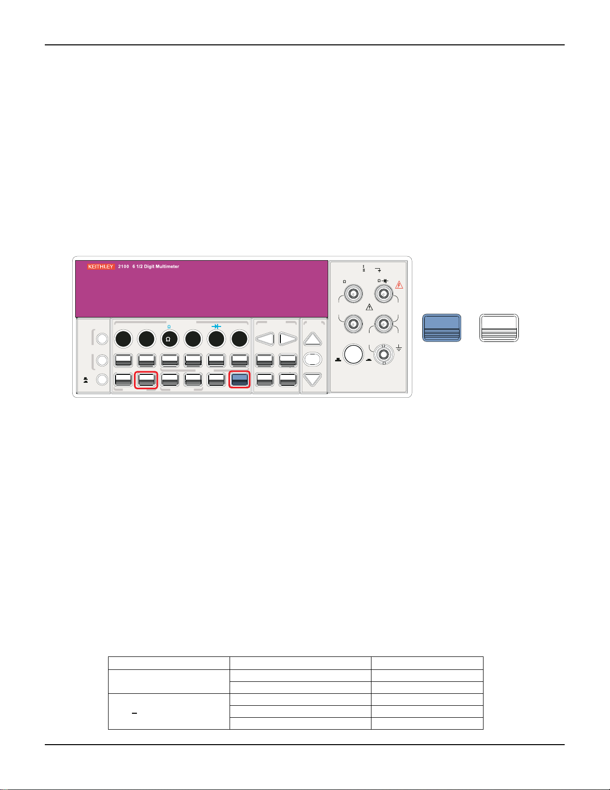
Model 2100 6 1/2-Digit Resolution Digital Multimeter User’s Manual Section 4: Front Panel Operations
2
V
2
Reading hold
The reading hold feature is used to hold a stable reading on the display. When a reading is stable,
enabling the reading hold will hold the stable reading and trigger a beeping sound. The reading
hold feature depends on an adjustable sensitivity band to determine if a reading is stable. The
Model 2100 Digital Multimeter considers a reading stable when three consecutive readings are
within the sensitivity band. Refer to "Sensitivity band (hold)" for a description of how to adjust the
sensitivity band.
To enable the reading hold feature (this feature is only available from the front panel):
1. Press both the SHIFT and AUTO TRIGGER keys.
2. To disable reading hold, simply press AUTO TRIGGER (refer to Figure 4-14).
Figure 4-14
Reading hold
CAT 1000V
CAT 600V
4 WIRE
RATIO
REF
INPUTS
LO
RMS
INPUT
HI
1000V
PEAK
SHIFT
3A
500V
PEAK
R
3A 250V
AMPS
+
AUT O
TRIGGER
DISPLAY
OFF
ON
PREV
NEXT
POWER
DCI ACI
DCV
ACV
ACV
DIGITS
HOLD
AUTO
TRIGGER
LIMITS MX+B
RATIO
STORE
FILTER
EXTRIG
SINGLE
TRIGGER MEMORY
FUNCTION
4
2
2
PERIOD
FREQ
%
RECALL
MATH
CONT
dBm
MIN/MAX
LOCAL
TEMP
dB
NULL
SHIFT
PREV
LOCK
ESC
CONFIG
SETUP
NEXT
ENTER
MENU
RANGE
AUTO
PEAK
200V
F
SENSE
FRONT/REAR
Trigger delay
This feature is useful if you need a longer delay time while the system is stabilizing. The time
needed to stabilize a measurement system is called the "settling time." The settling time depends
on the measurement range, cable properties, and signal source.
Trigger delay defaults
The default setting for trigger delay is automatically applied if you do not specify a delay value. The
Model 2100 will automatically select a delay time based on the measurement settings. A list of the
default settings for each measurement function is shown in Table 4-3. The time range for trigger
delay is from 0 to 3,600 seconds. Your selection of delay time is stored in volatile memory; the
default delay time will be restored when the meter is turned-off.
The internal settings of automatic trigger delay
The delay time for automatic trigger delay is determined by the selected combination of
measurement function, range, integration time, and AC filter speed (refer to Table 4-4 for default
measurement delay times).
Table 4-4
Default measurements
Measurement Setting Trigger delay time
DCV/DCI PLC > = 1 1.5ms
PLC < 1 1.0ms
Ω 2 and Ω 4
(PLC>
1)
100Ω ~ 100kΩ 1.5ms
1MΩ 15ms
10MΩ ~ 100MΩ 100ms
2100-900-01 Rev. E / March 2012 Return to Sect io n Topics 4-19

Section 4: Front Panel Operations Model 2100 6 1/2-Digit Resolution Digital Multimeter User’s Manual
FILTER
NEXT
PREV
DIGITS
RATIO
%
MIN/MAX
NULL
ESC
ENTER
AUTO
SINGLE
TRIGGER
STORE
RECALL
LOCAL
SHIFT
CONFIG
MENU
AUTO
DCV
ACV
22
FREQ
CONT
TEMP
4 WIRE
RATIO
V
INPUT
PEAK
200V
PEAK
HI
LO
PEAK
500V
3A
RMS
INPUTS
3A 250V
FRONT/REAR
AMPS
R
1000V
REF
CAT 1000V
CAT 600V
LOCK
SETUP
ACV
22
FUNCTION
DCI ACI
4
PERIOD
LIMITS MX+B
dB
EXTRIG
HOLD
MATH
TRIGGER MEMORY
dBm
RANGE
DISPLAY
NEXT
PREV
POWER
OFF
ON
SENSE
F
NEXT
PREV
ENTER
AUTO
MENU
Table 4-4 (continued)
Default measurements
Ω 2 and Ω 4
(PLC>1)
100Ω ~ 100kΩ 1.0ms
1MΩ 10ms
10MΩ ~ 100MΩ 100ms
Measurement Setting Trigger delay time
ACV / ACI
(remote interface/external
trigger/single trigger)
ACV / ACI
(Front panel w/ auto
trigger ON)
Frequency / period Remote interface / external 1.0s
3Hz 7.0s
20Hz 1.0s
200Hz 600ms
3Hz 1.5s
20Hz 200ms
200Hz 100ms
Front panel w/ auto trigger on 0s
Setting delay time
You can set the delay time from either the front panel or a remote interface.
To set the delay time from the front panel:
1. Press the MENU key and use the PREV and NEXT keys to select TRIG, then p ress ENTER.
2. Use the PREV and NEXT keys to select DELAY, then press ENTER.
3. Use the up and down arrow keys to move through the digits and to set the desired delay
time (between 0 to 3600 seconds). Refer to Figure 4-15 for the location of the keys.
Figure 4-15
Setting delay time from the front panel
To set the delay time from the remote interface:
You can either set the delay time or set the trigger delay to automatic operation from your PC
terminal using these commands:
TRIGger:DELay {<seconds>|MINimum|MAXimum}
or
TRIGger:DELay:AUTO {OFF|ON}
Math operations
The Model 2100 Digital Multimeter can perform eight math operations: RATIO, %, Min/Max, NULL,
4-20 Return to Section Topics 2100-900-01 Rev. E / March 2012
Limits, MX+B, dB, and dBm testing. Data from meas urement s ta ken are eithe r stored for late r use,

Model 2100 6 1/2-Digit Resolution Digital Multimeter User’s Manual Section 4: Front Panel Operations
DC input voltage
DC reference voltage
Ratio =
FILTER
NEXT
PREV
DIGITS
RATIO
%
MIN/MAX
NULL
ESC
ENTER
AUTO
SINGLE
TRIGGER
STORE
RECALL
LOCAL
SHIFT
CONFIG
MENU
AUTO
DCV
ACV
22
FREQ
CONT
TEMP
4 WIRE
RATIO
V
INPUT
PEAK
200V
PEAK
HI
LO
PEAK
500V
3A
RMS
INPUTS
3A 250V
FRONT/REAR
AMPS
R
1000V
REF
CAT 1000V
CAT 600V
LOCK
SETUP
ACV
22
FUNCTION
DCI ACI
4
PERIOD
LIMITS MX+B
dB
EXTRIG
HOLD
MATH
TRIGGER MEMORY
dBm
RANGE
DISPLAY
NEXT
PREV
POWER
OFF
ON
SENSE
F
NEXT
PREV
RATIO
ENTER
CONFIG
INPUTS
or used to perform mathematical operations on the readings. Note that these math operations are
available to all measurement functions except continuity and diode testing.
NOTE The "MAT H" annunciator on the display indicates th e st ate of a mathemat ical featur e and
will be lit when any math feature (excluding Ratio) is enabled. Press the same keys again
to disable the math feature.
NOTE When you press the RATIO key, the "RATIO" annunciator is lit on the display.
Ratio
Definition
The Ratio function calculates the ratio of an input DC voltage to a reference DC voltage , using the
following equation:
How to make a Ratio measurement
There are two ways to make a Ratio measurement: Using the front panel, or using a remote
interface.
To make a Ratio measurement from the front panel:
1. Use the INPUTS button to select the front or rear terminals.
2. Connect the DC input signal to the INPUT HI and LO terminals. Connect the reference
signal to the SENSE HI and LO terminals. Connect the SENSE LO to the INPUT LO
terminal.
3. Press CONFIG + RATIO, then use the PREV and NEXT keys to select the
RESOLUTION option (refer to "Resolution settings (digits)") and press ENTER.
4. Select the desired value by pressing the left, right, up, and down arrow keys, then press
ENTER.
5. To start the Ratio function, press the RATIO key and observe the reading on the display
(Figure 4-16 shows the location of the keys used).
NOTE To close this function, press one of the measurement function keys.
Figure 4-16
Making a Ratio measurement from the front panel
2100-900-01 Rev. E / March 2012 Return to Section T o pics 4-21

Section 4: Front Panel Operations Model 2100 6 1/2-Digit Resolution Digital Multimeter User’s Manual
Input reading • 100
Target value
Percent =
2
V
2
To make a ratio measurement using a remote interface:
Use the following command to make a Ratio measurement:
CONFigure:VOLTage:DC:RATio{<range>|MIN|MAX|DEF},{<resolution>|MIN|MAX|DEF}
% (Percent)
Definition
This mathematical function calculates the ratio of a measurement reading to a specified target
value in the form of a percentage. The calculation formula is shown below:
The specified target value is stored in volatile memory and will be cleared after the meter has
been turned-off or a remote interface has been reset.
Making a percent measurement
You can make a percent measurement using the front panel or through a remote interface.
To make a percent measurement using the front panel:
1. To specify a target value, first configure the % function by pressing CONFIG + %.
2. Use the PREV and NEXT keys to move through the digits, and the up and down arrow
keys to increase or decrease the numbers to a desired target va lue.
3. Press ENTER to set the value.
4. Press % to activate this function, then observe the calculated percent value on the display
(Figure 4-17 shows the location of the keys used).
NOTE Press % again to disable this function. The "MATH" annunciator on the display indicates
the state of a mathematical feature.
Figure 4-17
Making a percent measurement from the front panel
CAT 1000V
CAT 600V
4 WIRE
RATIO
REF
INPUTS
LO
RMS
INPUT
HI
1000V
PEAK
3A
500V
PEAK
R
3A 250V
AMPS
CONFIG
PREV
%
NEXT
ENTER
DISPLAY
OFF
ON
PREV
NEXT
POWER
DCI ACI
DCV
ACV
ACV
DIGITS
HOLD
AUTO
TRIGGER
LIMITS MX+B
RATIO
FILTER
EXTRIG
SINGLE
TRIGGER MEMORY
FUNCTION
4
2
2
STORE
PERIOD
FREQ
%
RECALL
MATH
CONT
dBm
MIN/MAX
LOCAL
TEMP
dB
NULL
SHIFT
PREV
LOCK
ESC
CONFIG
SETUP
NEXT
ENTER
MENU
RANGE
AUTO
200V
PEAK
F
SENSE
FRONT/REAR
To make a percent measurement from a remote interface:
Use the following commands to enable and configure the % function:
4-22 Return to Section Topics 2100-900-01 Rev. E / March 2012

Model 2100 6 1/2-Digit Resolution Digital Multimeter User’s Manual Section 4: Front Panel Operations
2
V
2
2
CALCulate:FUNCtion PERCent
CALCulate:STATe {OFF|ON}
CALCulate:STATe?
CALCulate:PERCent:TARGet{<value>|MINimum|MAXimum}
CALCulate:PERCent:TARGet? [MINimum|MAXimum
MIN/MAX
Definition:
When the MIN/MAX function is enabled, the multimeter takes in a series of readings from the
measurements, stores the minimum and maximum readings in memory, and then calculates the
average value of all readings. The number of readings taken since the MIN/MAX operation is
enabled is also stored in memory. These data are stored in volatile memory and will be cleared
when the meter is turned off, when MIN/MAX is turned on, or after a remote interface reset. The
meter beeps every time it captures a new minimum or maximum.
Using MIN/MAX
You can use the MIN/MAX feature either through the front panel or a remote interface.
To use the MIN/MAX function from the front panel:
1. First select the measurement function you want to use.
2. Press the MIN/MAX key to enable the MIN/MAX function.
3. To read the MIN/MAX value, the average value, or the readings count, press the CONFIG
key, and then the MIN/MAX key. Use the PREV and NEXT keys to switch between those
values (refer to Figure 4-18).
NOTE Press MIN/MAX again to disable this feature. The "MATH" annunciator on the display
indicates the state of a mathematical feature.
Figure 4-18
Using MIN/MAX from the front panel
CAT 1000V
CAT 600V
4 WIRE
RATIO
REF
INPUTS
RMS
INPUT
HI
LO
3A
R
3A 250V
AMPS
1000V
PEAK
500V
PEAK
DCV
ACVACV
FREQ
MIN/MAX
PREV
222
TEMP
CONFIG
NEXT
DISPLAY
OFF
ON
PREV
NEXT
POWER
DCI ACI
DCV
ACV
ACV
DIGITS
HOLD
AUTO
TRIGGER
LIMITS MX+B
RATIO
STORE
FILTER
EXTRIG
SINGLE
TRIGGER MEMORY
FUNCTION
4
2
2
PERIOD
FREQ
%
RECALL
MATH
CONT
dBm
MIN/MAX
LOCAL
TEMP
dB
NULL
SHIFT
PREV
LOCK
ESC
CONFIG
SETUP
NEXT
ENTER
MENU
RANGE
AUTO
PEAK
200V
F
SENSE
FRONT/REAR
To use the Min/Max function from a remote interface:
The following commands can be used with the Min/Max operation from your PC terminal:
2100-900-01 Rev. E / March 2012 Return to Section T o pics 4-23

Section 4: Front Panel Operations Model 2100 6 1/2-Digit Resolution Digital Multimeter User’s Manual
CALCulate:FUNCtion AVERage
CALCulate:STATe {OFF|ON}
CALCulate:STATe?
CALCulate:AVERage:MINimum?
CALCulate:AVERage:MAXimum?
CALCulate:AVERage:AVERage?
CALCulate:AVERage:COUNt?
Null
Definition
When the Null function is enabled, the displayed measurement reading is the difference between
the measured input signal reading and the stored null (also called relative) value. The null
(relative) value is stored in volatile memory, which will be cleared when the multimeter is shut off.
You can also specify or alter a null value. The null feature is available for all functions (except
continuity and diode). When you select the null feat ure for a measurement, it is visible only for one
measurement.
Using the Null (relative) function You can activate the Null function from either the front panel or a remote interface. To use the Null function from the front panel:
NOTE Null measurements can be used with any function except continuity and diode.
1. To store the null test lead resistance, short/connect the two test leads together and then
press the NULL key. The new reading taken will replace the old value (if any) in the null
register.
2. Connect the two test leads to the input source. The null offset value will show on the display
(refer to Figure 4-19 for the keys to use).
The null offset value can also be adjusted manually from the front panel:
1. Press CONFIG, then NULL.
2. Use the PREV and NEXT keys to move through the digits, and use the up and down arrow
keys to increase or decrease the numbers to the desired value.
3. Press ENTER.
NOTE Press NULL again to disable this feature. The "MATH" annunciator on the display
indicates the state of a mathematical feature.
4-24 Return to Section Topics 2100-900-01 Rev. E / March 2012

Model 2100 6 1/2-Digit Resolution Digital Multimeter User’s Manual Section 4: Front Panel Operations
FILTER
NEXT
PREV
DIGITS
RATIO
%
MIN/MAX
NULL
ESC
ENTER
AUTO
SINGLE
TRIGGER
STORE
RECALL
LOCAL
SHIFT
CONFIG
MENU
AUTO
DCV
ACV
22
FREQ
CONT
TEMP
4 WIRE
RATIO
V
INPUT
PEAK
200V
PEAK
HI
LO
PEAK
500V
3A
RMS
INPUTS
3A 250V
FRONT/REAR
AMPS
R
1000V
REF
CAT 1000V
CAT 600V
LOCK
SETUP
ACV
22
FUNCTION
DCI ACI
4
PERIOD
LIMITS MX+B
dB
EXTRIG
HOLD
MATH
TRIGGER MEMORY
dBm
RANGE
DISPLAY
NEXT
PREV
POWER
OFF
ON
SENSE
F
NEXT
PREV
NULL
ENTER
CONFIG
Figure 4-19
Using the NULL function from the front panel
To use the NULL function from a remote interface:
You can use the following commands on your PC terminal to make a Null measurement:
CALCulate:FUNCtion
NULLCALCulate:STATe {OFF|ON}
CALCulate:STATe?
CALCulate:NULL:OFFSet {<value>|MAXimum|MINimum}
Limits test
Definition
The limits testing operation allows you to adjust maximal and minimal limit values. The multimeter
beeps and a "HI" or "LO" message will be shown when the reading exceeds the upper or lower
limits. When you specify the limit values, they are stored in volatile memory. The default values for
both upper and lower limits are "0." This function can be used with all measurements (except
continuity and diode measurements).
Setting limits values or making a limits test
You can set limit values or make a limits test either through the front panel or a remote interface.
To set limits values from the front panel:
1. Configure the Limits math function by pressing CONFIG + SHIFT + RATIO, and then use
the PREV and NEXT keys to select either MIN or MAX, and press ENTER.
2. Use the PREV and NEXT keys to move through the digits and the up and down arrow
keys to increase or decrease the numbers to a desired value.
3. Press ENTER to set the value (refer to Figure 4-20).
2100-900-01 Rev. E / March 2012 Return to Section T o pics 4-25

Section 4: Front Panel Operations Model 2100 6 1/2-Digit Resolution Digital Multimeter User’s Manual
FILTER
NEXT
PREV
DIGITS
RATIO
%
MIN/MAX
NULL
ESC
ENTER
AUTO
SINGLE
TRIGGER
STORE
RECALL
LOCAL
SHIFT
CONFIG
MENU
AUTO
DCV
ACV
22
FREQ
CONT
TEMP
4 WIRE
RATIO
V
INPUT
PEAK
200V
PEAK
HI
LO
PEAK
500V
3A
RMS
INPUTS
3A 250V
FRONT/REAR
AMPS
R
1000V
REF
CAT 1000V
CAT 600V
LOCK
SETUP
ACV
22
FUNCTION
DCI ACI
4
PERIOD
LIMITS MX+B
dB
EXTRIG
HOLD
MATH
TRIGGER MEMORY
dBm
RANGE
DISPLAY
NEXT
PREV
POWER
OFF
ON
SENSE
F
NEXT
PREV
RATIO
ENTER
SHIFT
CONFIG
FILTER
NEXT
PREV
DIGITS
RATIO
%
MIN/MAX
NULL
ESC
ENTER
AUTO
SINGLE
TRIGGER
STORE
RECALL
LOCAL
SHIFT
CONFIG
MENU
AUTO
DCV
ACV
22
FREQ
CONT
TEMP
4 WIRE
RATIO
V
INPUT
PEAK
200V
PEAK
HI
LO
PEAK
500V
3A
RMS
INPUTS
3A 250V
FRONT/REAR
AMPS
R
1000V
REF
CAT 1000V
CAT 600V
LOCK
SETUP
ACV
22
FUNCTION
DCI ACI
4
PERIOD
LIMITS MX+B
dB
EXTRIG
HOLD
MATH
TRIGGER MEMORY
dBm
RANGE
DISPLAY
NEXT
PREV
POWER
OFF
ON
SENSE
F
SHIFT
DCV
FREQ
TEMP
ACVACV
2222
RATIO
Figure 4-20
Configuring the Limits function from the front panel
To make a limits test from the front panel:
1. Select any measurement function (except continuity and diode).
2. Enable the Limits function by pressing the SHIFT + RATIO keys.
3. After enabling the Limits function, you can set the limits values as described above.
4. Observe the displayed reading (refer to Figure 4-21 for the location of the keys to use).
NOTE Press SHIFT + RATIO again to disable this feature. The "MATH" annunciator on the
display indicates the state of a mathematical feature.
Figure 4-21
Making a limits test from the front panel
To enable the Limits function or set limits values from a remote interface:
Use the following commands to enable the Limits function or to set the limits values:
CALCulate:FUNCtion
LIMitCALCulate:STATe {OFF|ON}
CALCulate:STATe?
CALCulate:LIMit:LOWer {<value>|MINimum|MAXimum}
CALCulate:LIMit:UPPer {<value>|MINimum|MAXimum}
MX+B
Definition
4-26 Return to Section Topics 2100-900-01 Rev. E / March 2012

Model 2100 6 1/2-Digit Resolution Digital Multimeter User’s Manual Section 4: Front Panel Operations
FILTER
NEXT
PREV
DIGITS
RATIO
%
MIN/MAX
NULL
ESC
ENTER
AUTO
SINGLE
TRIGGER
STORE
RECALL
LOCAL
SHIFT
CONFIG
MENU
AUTO
DCV
ACV
22
FREQ
CONT
TEMP
4 WIRE
RATIO
V
INPUT
PEAK
200V
PEAK
HI
LO
PEAK
500V
3A
RMS
INPUTS
3A 250V
FRONT/REAR
AMPS
R
1000V
REF
CAT 1000V
CAT 600V
LOCK
SETUP
ACV
22
FUNCTION
DCI ACI
4
PERIOD
LIMITS MX+B
dB
EXTRIG
HOLD
MATH
TRIGGER MEMORY
dBm
RANGE
DISPLAY
NEXT
PREV
POWER
OFF
ON
SENSE
F
NEXT
PREV
%
ENTER
SHIFT
CONFIG
This mathematical function multiplies a measurement reading (X) by a specified scale factor (M),
and adds an offset (B) automatically. The answer (Y) will then be shown on the display according
to the following equation:
Y=MX+B
This is especially useful when you need to do slope calculations on a series of measurements.
The values of the "M" and "B" can be changed through the configuration of this function; these
values are stored in volatile memory until the meter has been turned off or the remote interface is
reset. You can use either the front panel or remote interface to pe rform this function and set the s e
two constants.
To use the MX+B function from the front panel:
NOTE Set the values of M and B before selecting a measurement function.
1. Set the values of M and B for your math function by pressing CONFIG and SHIFT + %.
2. Use the PREV and NEXT keys to switch between M and B, and press ENTER on your
selection.
3. Then use the PREV and NEXT keys to move through the digits, and use the up and down
arrow keys to increase or decrease the number to the desired value.
4. Press ENTER to set the value.
5. Select a measurement function and press SHIFT + % to activate the MX+B function (refer to
Figure 4-22).
Figure 4-22
Using the MX+B function from the front panel
To use the MX+B function from a remote interface:
Use the following commands to enable and configure the MX+B function:
CALCulate:FUNCtion MXB
CALCulate:STATe {OFF|ON}
CALCulate:STATe?
CALCulate:MXB:MMFactor {<value>|MINimum|MAXimum}
CALCulate:MXB:MMFactor? [MINimum|MAXimum]
CALCulate:MXB:MBFactor {<value>|MINimum|MAXimum}
CALCulate:MXB:MBFactor? [MINimum|MAXimum]
dB
2100-900-01 Rev. E / March 2012 Return to Section T o pics 4-27
Definition

Section 4: Front Panel Operations Model 2100 6 1/2-Digit Resolution Digital Multimeter User’s Manual
FILTER
NEXT
PREV
DIGITS
RATIO
%
MIN/MAX
NULL
ESC
ENTER
AUTO
SINGLE
TRIGGER
STORE
RECALL
LOCAL
SHIFT
CONFIG
MENU
AUTO
DCV
ACV
22
FREQ
CONT
TEMP
4 WIRE
RATIO
V
INPUT
PEAK
200V
PEAK
HI
LO
PEAK
500V
3A
RMS
INPUTS
3A 250V
FRONT/REAR
AMPS
R
1000V
REF
CAT 1000V
CAT 600V
LOCK
SETUP
ACV
22
FUNCTION
DCI ACI
4
PERIOD
LIMITS MX+B
dB
EXTRIG
HOLD
MATH
TRIGGER MEMORY
dBm
RANGE
DISPLAY
NEXT
PREV
POWER
OFF
ON
SENSE
F
NEXT
PREV
NULL
ENTER
SHIFT
CONFIG
The dB feature takes a DC or AC voltage measurement and displays it in decibel units that
correspond with a relative reference value. The calculation of dB is listed below:
dB = 20 x log(Vin / Vref)
or
dB = (Input signal in dBm) - (relative value in dBm)
NOTE The Vin is the input signal and the Vref is the relative reference.
The dB measurement is applied to DC and AC voltage only. The relative value is adjustable (from
0dBm to 200dBm) and is stored in volatile memory.
Setting the relative reference value
You can either manually select a number for the relative reference, or let the multimeter take the
first reading (0dB):
To set the relative reference value from the front panel:
1. Press the CONFIG + SHIFT + NULL keys.
2. Use the PREV and NEXT keys to move through the digits and the up and down arrow keys
to increase or decrease the numbers to the desired value.
3. Press ENTER to set the value (refer to Figure 4-23).
Figure 4-23
Setting the relative reference value
To make a dB measurement from the front panel:
1. Select the measurement function by pressing one of the DCV or ACV keys.
2. Enable the dB operation by pressing SHIFT + NULL keys.
3. After enabling the dB operation, you can set or alter the dB relative value as mentioned
above.
4. Observe the displayed reading (refer to Figure 4-24 for the location of the keys used).
NOTE Press SHIFT + NULL again to disable this feature. The "MATH" annunciator on the
display indicates the state of a mathematical feature.
4-28 Return to Section Topics 2100-900-01 Rev. E / March 2012

Model 2100 6 1/2-Digit Resolution Digital Multimeter User’s Manual Section 4: Front Panel Operations
FILTER
NEXT
PREV
DIGITS
RATIO
%
MIN/MAX
NULL
ESC
ENTER
AUTO
SINGLE
TRIGGER
STORE
RECALL
LOCAL
SHIFT
CONFIG
MENU
AUTO
DCV
ACV
22
FREQ
CONT
TEMP
4 WIRE
RATIO
V
INPUT
PEAK
200V
PEAK
HI
LO
PEAK
500V
3A
RMS
INPUTS
3A 250V
FRONT/REAR
AMPS
R
1000V
REF
CAT 1000V
CAT 600V
LOCK
SETUP
ACV
22
FUNCTION
DCI ACI
4
PERIOD
LIMITS MX+B
dB
EXTRIG
HOLD
MATH
TRIGGER MEMORY
dBm
RANGE
DISPLAY
NEXT
PREV
POWER
OFF
ON
SENSE
F
NULL
SHIFT
DCV
ACVACV
Figure 4-24
Making a dB measurement from the front panel
To make a dB measurement from a remote interface:
Use the following commands from your PC terminal to make the dB measurement:
CALCulate:FUNCtion DB
CALCulate:STATe {OFF|ON}
CALCulate:STATe?
CALCulate:DB:REFerence {<value>|MINimum|MAXimum}
dBm
Definition
With dBm selected, a voltage measurement is displayed as the level of power (relative to 1
milliwatt) dissipated through a reference resistance. The reference resistance is adjustable in the
Model 2100 Digital Multimeter. The calculation of dBm is defined as below:
dBm = 10 x log(V
NOTE Vin is the input signal voltage; Zref is the reference resistance. Changing the reference
resistance will not affect the stored relative reference value. The Zref is adjustable, with a
range from 50Ω to 8000Ω (the default value is 600Ω ). The user-selected reference
value is stored in volatile memory and will be cleared after the multimeter has been shutoff. This feature is available for DCV and ACV only.
Setting the reference resistance
You can set the reference resistance either through the front panel or from a remote interface.
To set the reference resistance from the front panel:
1. Press the CONFIG + SHIFT + MIN/MAX keys.
2. Use the PREV and NEXT keys to move through the digits and the up and down arrow keys
to increase or decrease the numbers to the desired value.
3. Press ENTER to set the value (refer to Figure 4-25 for the location of the keys used).
2
/Z
)/1mW
in
ref
2100-900-01 Rev. E / March 2012 Return to Section T o pics 4-29

Section 4: Front Panel Operations Model 2100 6 1/2-Digit Resolution Digital Multimeter User’s Manual
FILTER
NEXT
PREV
DIGITS
RATIO
%
MIN/MAX
NULL
ESC
ENTER
AUTO
SINGLE
TRIGGER
STORE
RECALL
LOCAL
SHIFT
CONFIG
MENU
AUTO
DCV
ACV
22
FREQ
CONT
TEMP
4 WIRE
RATIO
V
INPUT
PEAK
200V
PEAK
HI
LO
PEAK
500V
3A
RMS
INPUTS
3A 250V
FRONT/REAR
AMPS
R
1000V
REF
CAT 1000V
CAT 600V
LOCK
SETUP
ACV
22
FUNCTION
DCI ACI
4
PERIOD
LIMITS MX+B
dB
EXTRIG
HOLD
MATH
TRIGGER MEMORY
dBm
RANGE
DISPLAY
NEXT
PREV
POWER
OFF
ON
SENSE
F
NEXT
PREV
MIN/MAX
ENTER
SHIFT
CONFIG
FILTER
NEXT
PREV
DIGITS
RATIO
%
MIN/MAX
NULL
ESC
ENTER
AUTO
SINGLE
TRIGGER
STORE
RECALL
LOCAL
SHIFT
CONFIG
MENU
AUTO
DCV
ACV
22
FREQ
CONT
TEMP
4 WIRE
RATIO
V
INPUT
PEAK
200V
PEAK
HI
LO
PEAK
500V
3A
RMS
INPUTS
3A 250V
FRONT/REAR
AMPS
R
1000V
REF
CAT 1000V
CAT 600V
LOCK
SETUP
ACV
22
FUNCTION
DCI ACI
4
PERIOD
LIMITS MX+B
dB
EXTRIG
HOLD
MATH
TRIGGER MEMORY
dBm
RANGE
DISPLAY
NEXT
PREV
POWER
OFF
ON
SENSE
F
SHIFT
MIN/MAX
DCV
ACVACV
Figure 4-25
Setting the reference resistance from the front panel
Making a dBm measurement
To make a dBm measurement from the front panel:
1. Select the measurement function by pressing one of the DCV or ACV keys (the dBm feature
is only available for the DCV and ACV functions).
2. Enable the dBm operation by pressing SHIFT + MIN/MAX keys.
3. After enabling the dBm operation, you can set or alter the dBm relative value as mentioned
above.
4. Observe the displayed reading (refer to Figure 4-26 for the location of the keys used).
NOTE Press SHIFT + MIN/MAX again to disable this feature. The "MATH" annunciator on the
display indicates the state of a mathematical feature.
Figure 4-26
Making a dBm measurement from the front panel
To make a dBm measurement from a remote interface:
Use the following commands from your PC terminal to make the dBm measurement:
4-30 Return to Section Topics 2100-900-01 Rev. E / March 2012

Model 2100 6 1/2-Digit Resolution Digital Multimeter User’s Manual Section 4: Front Panel Operations
CALCulate:FUNCtion DBM
CALCulate:STATe {OFF|ON}
CALCulate:STATe?
CALCulate:DBM:REFerence {<value>|MINimum|MAXimum}
Other system-related operations
Each system-related operation performs a task that is not measurement-related but plays an
important role in making your measurements.
Display
Definition
The Model 2100 Digital Multimeter has a 5x7 dot-matrix, dual display with three-color (white, red
and yellow) annunciators for better viewing. A maximum of 13 characters are allowed for upper
row dot-matrix display, and a maximum 16 characters are allowed for lower row dot-matrix d isplay
(refer to Figure 4-27).
Figure 4-27
The Model 2100 dot-matrix display screen
You also have the option to turn off measurement readings on the instrument display for faster
measurements. When "OFF" is lit at the lower right corner of the display screen, measurement
readings will not be sent to the instrument display, but can be viewed later from a remote interface
(note that this does not mean the display is turned-off). This option accelerates the measurement
process because there is no I/O delay. Turning-off the measurement readings on the instrument
display will not affect the messages displayed from the Recall, Menu, and Config operations.
NOTE Messages sent from a remote interface (for instance, your PC terminal) will replace the
messages on the lower row of the original instrument display.
Default
The instrument display default is "ON." If you change the "ON/OFF" setting (which is stored in
volatile memory), the default setting will be restored when the meter is shut-off.
Controlling the Model 2100 display
You can control the instrument display through the front panel or using a remote interface.
NOTE Messages sent from a remote interface will have priority over messages sent from the
front panel.
To control the instrument display from the front panel:
1. Press the MENU key.
2. Use the PREV and NEXT keys to select the SYSTEM submenu and press ENTER.
2100-900-01 Rev. E / March 2012 Return to Section T o pics 4-31

Section 4: Front Panel Operations Model 2100 6 1/2-Digit Resolution Digital Multimeter User’s Manual
FILTER
NEXT
PREV
DIGITS
RATIO
%
MIN/MAX
NULL
ESC
ENTER
AUTO
SINGLE
TRIGGER
STORE
RECALL
LOCAL
SHIFT
CONFIG
MENU
AUTO
DCV
ACV
22
FREQ
CONT
TEMP
4 WIRE
RATIO
V
INPUT
PEAK
200V
PEAK
HI
LO
PEAK
500V
3A
RMS
INPUTS
3A 250V
FRONT/REAR
AMPS
R
1000V
REF
CAT 1000V
CAT 600V
LOCK
SETUP
ACV
22
FUNCTION
DCI ACI
4
PERIOD
LIMITS MX+B
dB
EXTRIG
HOLD
MATH
TRIGGER MEMORY
dBm
RANGE
DISPLAY
NEXT
PREV
POWER
OFF
ON
SENSE
F
NEXT
PREV
ENTER
MENU
3. Use the PREV and NEXT keys to select the DISPLAY submenu and press ENTER.
4. Use the PREV and NEXT keys to select either ON or OFF and press ENTER (refer to
Figure 4-28).
Figure 4-28
Controlling the display from the front panel
Controlling the display from a remote interface
Beeper
To control the instrument display from a remote interface:
Use the following commands to control the instrument display, or to send a message to the
display:
DISPlay {OFF|ON} Turns the display off or on
DISPlay:TEXT <quoted string> Displays the string you type in
DISPlay:TEXT:CLEar Clears the message displayed
Definition
The Model 2100 Digital Multimeter beeps when certain conditions are met or when an error
occurs. When you don't want the beeper to sound , you can disa ble it. Although you can turn off the
beeper, the click sound you hear when a key is pressed will not be disabled. The beeper state is
stored in volatile memory, and the default will be restored when the meter has been turned-off or
after a remote interface reset.
If the beeper is disabled, you will not hear meter beeps when:
• A new minimum or maximum is found in Min/Max operation.
• A stable reading is detected and held.
• The test voltage is within the limits in diode testing.
• The source signal fails the limit testing.
If the beeper is disabled, the meter still emits a tone when:
• An error occurs.
• Any key on the front panel is pressed.
• The threshold value is exceeded in continuity testing.
Default beeper setting
The beeper is enabled when it is shipped from the factory.
Controlling the beeper
4-32 Return to Section Topics 2100-900-01 Rev. E / March 2012

Model 2100 6 1/2-Digit Resolution Digital Multimeter User’s Manual Section 4: Front Panel Operations
FILTER
NEXT
PREV
DIGITS
RATIO
%
MIN/MAX
NULL
ESC
ENTER
AUTO
SINGLE
TRIGGER
STORE
RECALL
LOCAL
SHIFT
CONFIG
MENU
AUTO
DCV
ACV
22
FREQ
CONT
TEMP
4 WIRE
RATIO
V
INPUT
PEAK
200V
PEAK
HI
LO
PEAK
500V
3A
RMS
INPUTS
3A 250V
FRONT/REAR
AMPS
R
1000V
REF
CAT 1000V
CAT 600V
LOCK
SETUP
ACV
22
FUNCTION
DCI ACI
4
PERIOD
LIMITS MX+B
dB
EXTRIG
HOLD
MATH
TRIGGER MEMORY
dBm
RANGE
DISPLAY
NEXT
PREV
POWER
OFF
ON
SENSE
F
NEXT
PREV
ENTER
MENU
You can control the beeper from either the front panel or the remote interface.
To control the beeper from the front panel:
1. Press the MENU key then use the PREV and NEXT keys to select the SYSTEM
submenu, and press ENTER.
2. Use the PREV and NEXT keys to select the BEEP submenu, and press ENTER.
3. Use the PREV and NEXT keys to select ON or OFF and press ENTER
(refer to Figure 4-27).
Procedures: MENU SYSTEM BEEP {ON|OFF}
Figure 4-29
Controlling the beeper from the front panel
To control the beeper from a remote interface:
Use the following commands to disable or enable the beeper from a remote interface:
SYSTem:BEEPer
SYSTem:BEEPer:STATe {OFF|ON}
Reading memory (store and recall)
Definition
The Model 2100 Digital Multimeter has a memory capacity of 2000 readings. The readings are
stored in first-in-first-out order in volatile memory, which means the stored readings will be cleared
when the multimeter is turned-off. The reading memory feature can be used for all measurement
functions, math operations, trigger operations, and reading hold.
Using the reading memory
You can store readings and access those re ading s th ro ug h eit he r the fro n t panel or a remot e
interface.
NOTE Readings stored from the Model 2100 to a remote interface will be stored in first-in- first-
out order.
To store readings from the front panel:
NOTE When using the reading memory feature, you first need to select a measurement or math
function, then select the trigger mode.
1. Press the STORE key. The multimeter will start to store the readings produced until the
2. To change number of readings to store, press the CONFIG and then STORE keys.
2100-900-01 Rev. E / March 2012 Return to Section T o pics 4-33
specified number of readings is reached. The default number of readings to store is 100.

Section 4: Front Panel Operations Model 2100 6 1/2-Digit Resolution Digital Multimeter User’s Manual
FILTER
NEXT
PREV
DIGITS
RATIO
%
MIN/MAX
NULL
ESC
ENTER
AUTO
SINGLE
TRIGGER
STORE
RECALL
LOCAL
SHIFT
CONFIG
MENU
AUTO
DCV
ACV
22
FREQ
CONT
TEMP
4 WIRE
RATIO
V
INPUT
PEAK
200V
PEAK
HI
LO
PEAK
500V
3A
RMS
INPUTS
3A 250V
FRONT/REAR
AMPS
R
1000V
REF
CAT 1000V
CAT 600V
LOCK
SETUP
ACV
22
FUNCTION
DCI ACI
4
PERIOD
LIMITS MX+B
dB
EXTRIG
HOLD
MATH
TRIGGER MEMORY
dBm
RANGE
DISPLAY
NEXT
PREV
POWER
OFF
ON
SENSE
F
NEXT
PREV
ENTER
STORE
CONFIG
FILTER
NEXT
PREV
DIGITS
RATIO
%
MIN/MAX
NULL
ESC
ENTER
AUTO
SINGLE
TRIGGER
STORE
RECALL
LOCAL
SHIFT
CONFIG
MENU
AUTO
DCV
ACV
22
FREQ
CONT
TEMP
4 WIRE
RATIO
V
INPUT
PEAK
200V
PEAK
HI
LO
PEAK
500V
3A
RMS
INPUTS
3A 250V
FRONT/REAR
AMPS
R
1000V
REF
CAT 1000V
CAT 600V
LOCK
SETUP
ACV
22
FUNCTION
DCI ACI
4
PERIOD
LIMITS MX+B
dB
EXTRIG
HOLD
MATH
TRIGGER MEMORY
dBm
RANGE
DISPLAY
NEXT
PREV
POWER
OFF
ON
SENSE
F
NEXT
PREV
RECALL
3. Use PREV and NEXT keys to move between the digits and up and down arrow keys to
increase or decrease numbers as desired.
When ready, press ENTER (the default number of readings will be restored when the meter has
been turned off). Refer to Figure 4-30.
NOTE The "MEM" annunciator is lit while the multimeter stores readings, and then turned-off
when the specified number of readings is reached.
Procedures: CONFIG + STORE <NUMBER>
Figure 4-30
Storing readings from the front panel
To recall stored readings from the front panel:
1. Press the RECALL key . The multimeter will display all the stored readings starting from the
first reading.
2. Use the PREV and NEXT keys or the up and down arrow keys to move from the first
reading to the last reading the meter has stored (refer to Figure 4-31).
Figure 4-31
Recalling readings from the front panel
To store or retrieve readings from a remote interface:
Use the following commands from a remote interface to store or retrieve readings:
NOTE The value set for the Store function only can be set through front panel.
4-34 Return to Section Topics 2100-900-01 Rev. E / March 2012
INITiate Sets the multimeter to "wait-for-trigger" state; after a measurement is t aken,
measurement readings will be placed in the memory

Model 2100 6 1/2-Digit Resolution Digital Multimeter User’s Manual Section 4: Front Panel Operations
2
V
2
FETCh? Use this command to retrieve stored readings
DATA:POINts? Use this command to query the number of stored readings
Sensitivity band (Hold)
Definition:
The reading hold function captures and holds a stable reading on the display. The multimeter
beeps and holds the value when it detects a stable reading. The sensitivity band in reading hold
decides which reading is stable enough. This band is expressed as a percent of reading on the
selected range. The multimeter considers a reading stable when three consecutive values are
within the band; you can adjust this sensitivity band.
Default
The default band setting is 0.1%. Your setting is stored in a volatile memory, and will be cleared
after the meter has been turned-off.
Adjusting the sensitivity band
You can adjust the sensitivity band through the front panel.
To adjust the sensitivity band from the front panel:
1. Press the MENU key, then use the PREV and NEXT arrow keys to select the TRIG
submenu.
2. Press ENTER, then again use the PREV and NEXT arrow keys to select the READ HOLD
submenu.
3. Press ENTER, then use PREV and NEXT keys to choose the desired band.
4. Press ENTER to set the desired sensitivity band (refer to Figure 4-32).
Figure 4-32
Adjusting the sensitivity band from the front panel
CAT 1000V
CAT 600V
RATIO
REF
INPUTS
LO
RMS
INPUT
PREV
MENU
NEXT
ENTER
HI
1000V
PEAK
3A
500V
PEAK
R
3A 250V
AMPS
DISPLAY
OFF
ON
PREV
NEXT
POWER
DCI ACI
DCV
ACV
ACV
DIGITS
HOLD
AUTO
TRIGGER
LIMITS MX+B
RATIO
STORE
FILTER
EXTRIG
SINGLE
TRIGGER MEMORY
FUNCTION
4
2
2
PERIOD
FREQ
%
RECALL
MATH
CONT
dBm
MIN/MAX
LOCAL
TEMP
dB
NULL
SHIFT
PREV
LOCK
ESC
CONFIG
SETUP
NEXT
ENTER
MENU
RANGE
AUTO
200V
PEAK
F
SENSE
4 WIRE
FRONT/REAR
Initial mode
Definition
Initial mode has two settings: DEFAULT and SAVE DATA. You can select SAVE DA TA to save the
current configuration, or select DEFAULT to restore the factory default configuration after
restarting the Model 2100. The valid ranges for SAVE DATA are listed in Table 4- 5.
2100-900-01 Rev. E / March 2012 Return to Section T o pics 4-35

Section 4: Front Panel Operations Model 2100 6 1/2-Digit Resolution Digital Multimeter User’s Manual
FILTER
NEXT
PREV
DIGITS
RATIO
%
MIN/MAX
NULL
ESC
ENTER
AUTO
SINGLE
TRIGGER
STORE
RECALL
LOCAL
SHIFT
CONFIG
MENU
AUTO
DCV
ACV
22
FREQ
CONT
TEMP
4 WIRE
RATIO
V
INPUT
PEAK
200V
PEAK
HI
LO
PEAK
500V
3A
RMS
INPUTS
3A 250V
FRONT/REAR
AMPS
R
1000V
REF
CAT 1000V
CAT 600V
LOCK
SETUP
ACV
22
FUNCTION
DCI ACI
4
PERIOD
LIMITS MX+B
dB
EXTRIG
HOLD
MATH
TRIGGER MEMORY
dBm
RANGE
DISPLAY
NEXT
PREV
POWER
OFF
ON
SENSE
F
NEXT
PREV
ENTER
MENU
Table 4-5
Valid values of Save Dat a
No. Items of Save Data Contents
1Continuity
2 Diode
3 Temperature
dBm Reference resistance
4
mx + B Values: m, B
5
Reading hold Sensitivity band
6
Threshold resistance
Boundary voltage
Sensor type & units
To save settings or restore default settings from the front panel:
1. Press the MENU key and use the PREV and NEXT keys to select the SYSTEM submenu.
2. Press ENTER and use the PREV and NEXT keys to select the INIT MODE submenu.
3. Press ENTER, and use the PREV and NEXT keys to select either SAVE DATA to save your
current settings, or DEFAULT to return to default settings.
4. Press ENTER to save your selection (refer to Figure 4-33).
Figure 4-33
Saving or restoring default settings
Language
The Model 2100 Digital Multimeter supports two languages: Default and A34401.
To select a language:
1. Press the MENU key, and use the PREV and NEXT keys to select the SYSTEM
submenu.
2. Press ENTER, then use the PREV and NEXT keys to select the LANGUAGE submenu.
3. Press ENTER, then use the PREV and NEXT keys to select either Default or A34401.
Press ENTER to save your selection (refer to Figure 4-34).
4-36 Return to Section Topics 2100-900-01 Rev. E / March 2012

Model 2100 6 1/2-Digit Resolution Digital Multimeter User’s Manual Section 4: Front Panel Operations
FILTER
NEXT
PREV
DIGITS
RATIO
%
MIN/MAX
NULL
ESC
ENTER
AUTO
SINGLE
TRIGGER
STORE
RECALL
LOCAL
SHIFT
CONFIG
MENU
AUTO
DCV
ACV
22
FREQ
CONT
TEMP
4 WIRE
RATIO
V
INPUT
PEAK
200V
PEAK
HI
LO
PEAK
500V
3A
RMS
INPUTS
3A 250V
FRONT/REAR
AMPS
R
1000V
REF
CAT 1000V
CAT 600V
LOCK
SETUP
ACV
22
FUNCTION
DCI ACI
4
PERIOD
LIMITS MX+B
dB
EXTRIG
HOLD
MATH
TRIGGER MEMORY
dBm
RANGE
DISPLAY
NEXT
PREV
POWER
OFF
ON
SENSE
F
NEXT
PREV
ENTER
MENU
Figure 4-34
Selecting a language
Error condition
The error annunciator on the front panel display alerts you that the multimeter has an error
condition. If there are one or more syntax or hardware errors found, the error annunciator will be lit
to inform the user. The multimeter stores errors using the first-in-first-out (FIFO) order, and it can
record up to 20 errors in the error queue. The first error detected will be the first error retrieved.
Refer to Section 6 for the list of error messages.
Also note that:
• The error annunciator will be turned off when you have read the errors in the memory.
• If there is no error found when you check the error queue, the multimeter shows "NO
ERRORS."
• If there are more than 20 errors found, the last error in the error queue will be replaced with
"-350," which means there are too many errors.
• The error queue is cleared when the multimeter is turned off, or when a *CLS command is
received.
To check the error queue:
1. Press the MENU key, then use the PREV and NEXT keys to select the SYSTEM
submenu.
2. Press ENTER, then use the PREV and NEXT keys to select the ERROR option.
3. Press ENTER, and the message about the error queue will show on the display (refer to
Figure 4-35 for the location of the keys used). See Section 6 for descriptions of error
messages.
2100-900-01 Rev. E / March 2012 Return to Section T o pics 4-37

Section 4: Front Panel Operations Model 2100 6 1/2-Digit Resolution Digital Multimeter User’s Manual
FILTER
NEXT
PREV
DIGITS
RATIO
%
MIN/MAX
NULL
ESC
ENTER
AUTO
SINGLE
TRIGGER
STORE
RECALL
LOCAL
SHIFT
CONFIG
MENU
AUTO
DCV
ACV
22
FREQ
CONT
TEMP
4 WIRE
RATIO
V
INPUT
PEAK
200V
PEAK
HI
LO
PEAK
500V
3A
RMS
INPUTS
3A 250V
FRONT/REAR
AMPS
R
1000V
REF
CAT 1000V
CAT 600V
LOCK
SETUP
ACV
22
FUNCTION
DCI ACI
4
PERIOD
LIMITS MX+B
dB
EXTRIG
HOLD
MATH
TRIGGER MEMORY
dBm
RANGE
DISPLAY
NEXT
PREV
POWER
OFF
ON
SENSE
F
NEXT
PREV
ENTER
MENU
Figure 4-35
Checking the error queue
Firmware revision
Definition
The Model 2100 has three microprocessors for various internal systems. You can query the
multimeter to determine which revision of firmware is installed for each microprocessor.
To check the firmware revision:
1. Press the MENU key and then use the PREV and NEXT keys to select the SYSTEM
submenu.
2. Press ENTER, then use the PREV and NEXT keys to select the SYSTEM VER. option.
3. Press ENTER to select it; a three-part code in xx-xx-xx format will appear on the display.
The first part of the code, xx.xx, is the firmware version of the digital signal processor (DSP);
the second code, xx, represents the panel microprocessor; and the last code, xx, indicates
the front-end processor firmware version (refer to Figure 4-36).
Figure 4-36
Checking the firmware revision
Occasionally , updated firmware for th e Model 2100 is released. The Product Information CD-ROM
that came with your Model 2100 contains the latest firmware revision available at the time of
shipping; you can also download the latest version of the firmware from the Keithley Instruments
website, www.keithley.com.
4-38 Return to Section Topics 2100-900-01 Rev. E / March 2012
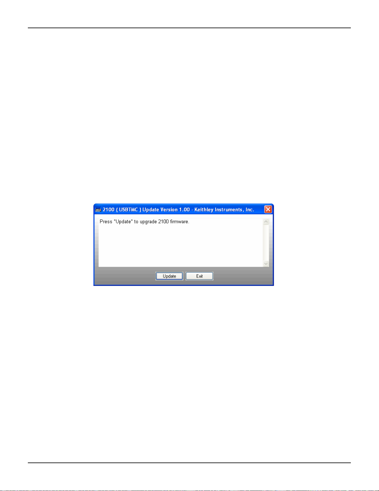
Model 2100 6 1/2-Digit Resolution Digital Multimeter User’s Manual Section 4: Front Panel Operations
To install updated firmware for the Model 2100:
NOTE You must have one of the following items installed on your computer in order to obtain
the proper VISA layer (Keithley Instruments I/O Layer 5.0 is included on the CD-ROM
that came with your Model 2100):
• Keithley Instruments I/O Layer 5.0 (KIOL-850BO5) or greater
• NI-VISA 3.1 or greater
• Agilent I/O Library Suite 14.2 or greater
1. Connect your Model 2100 to your computer with the included USB cable.
2. Insert the Product Information CD-ROM that came with your Model 2100 into the CD drive
of your computer (or navigate to the files you downloaded from the Keithley Instruments
website) and double-click the DmmUpdate.exe file to begin the installation of the Model
2100 firmware update.
3. When the 2100 (USBTMC) Update Version window appears, click the Select button (see
Figure 4-37).
Figure 4-37
Installing the Model 2100 firmware update
4. The Open dialog box will appear. The files for the front-end firmware and the digital signal
processor (DSP) updates are listed (see Figure 4-38):
• 1232_xxx.bin Updates the front-end firmware version
• 5407_xx.xx.bin Updates the DSP firmware version
NOTE Filenames may vary, depending upon which version of firmware you are installing. The
“xx.xx” and “xxx” in the filenames in this example represent alpha-numeric values that
denote specific firmware revisions.
2100-900-01 Rev. E / March 2012 Return to Section T o pics 4-39

Section 4: Front Panel Operations Model 2100 6 1/2-Digit Resolution Digital Multimeter User’s Manual
Figure 4-38
The Open dialog box
5. Highlight the 5407_xx.xx.bin file and click Open (see Figure 4-38) to start the DSP firmware
version update. The 2100 (USBTMC) Update Version window will display a "Please wait"
message while the file is executing, as shown in Figure 4-39.
Figure 4-39
Model 2100 firmware upgrade in progress
6. Once installation of the DSP firmware update file is complete, you will be prompted to
restart your Model 2100 to continue the update (see Figure 4-40). Power the Model 2100
off, and then power it on again.
Figure 4-40
Restart device to complete update message
4-40 Return to Section Topics 2100-900-01 Rev. E / March 2012
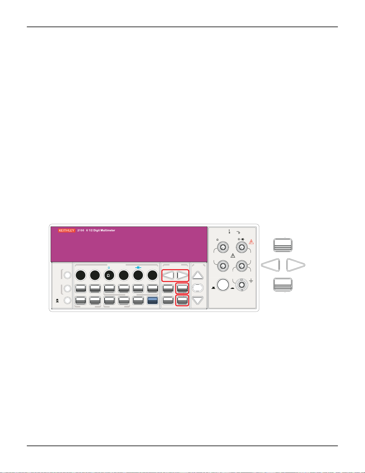
Model 2100 6 1/2-Digit Resolution Digital Multimeter User’s Manual Section 4: Front Panel Operations
FILTER
NEXT
PREV
DIGITS
RATIO
%
MIN/MAX
NULL
ESC
ENTER
AUTO
SINGLE
TRIGGER
STORE
RECALL
LOCAL
SHIFT
CONFIG
MENU
AUTO
DCV
ACV
22
FREQ
CONT
TEMP
4 WIRE
RATIO
V
INPUT
PEAK
200V
PEAK
HI
LO
PEAK
500V
3A
RMS
INPUTS
3A 250V
FRONT/REAR
AMPS
R
1000V
REF
CAT 1000V
CAT 600V
LOCK
SETUP
ACV
22
FUNCTION
DCI ACI
4
PERIOD
LIMITS MX+B
dB
EXTRIG
HOLD
MATH
TRIGGER MEMORY
dBm
RANGE
DISPLAY
NEXT
PREV
POWER
OFF
ON
SENSE
F
NEXT
PREV
ENTER
MENU
NOTE An error message may appear on the front-panel display when you restart your Model
2100. If it does, you will need to click Continue and install the front-end firmware revision
update file (1232_xxx.bin) following the procedures listed above.
If you do not receive an error message, you do not need to install the 1232_xxx.bin
update file.
7. The 2100 (USBTMC) Update Version window will reappear when the installation is
complete. Click Exit to exit the firmware update installation (see Figure 4-40).
To confirm the update has been properly completed, check the firmware revision number (see To
check the firmware revision).
Calibration
The Model 2100 will show the latest calibrated date and the next calibration date on the display
after following the operation below (refer to Figure 4-41 for the location of the keys used).
To view calibration information:
1. Press the MENU key, then use the PREV and NEXT keys to select the CALIBRATE option.
2. Press ENTER, then use the PREV and NEXT keys to switch between the last calibrated
date and the next calibration date.
Figure 4-41
Viewing calibration information
Self-test
Self-test procedures are built in the Model 2100 for checking that the logic and measurement
hardware are functioning properly. Every time the multimeter is powered on, a set of test
procedures is performed to make sure the basic function of the multimeter works properly. If any
error occurs during self-test procedures , it indica te s tha t parts of the multimete r ar e no t op erat i ng
properly and need to be serviced.
2100-900-01 Rev. E / March 2012 Return to Section T o pics 4-41

Section 4: Front Panel Operations Model 2100 6 1/2-Digit Resolution Digital Multimeter User’s Manual
FILTER
NEXT
PREV
DIGITS
RATIO
%
MIN/MAX
NULL
ESC
ENTER
AUTO
SINGLE
TRIGGER
STORE
RECALL
LOCAL
SHIFT
CONFIG
MENU
AUTO
DCV
ACV
22
FREQ
CONT
TEMP
4 WIRE
RATIO
V
INPUT
PEAK
200V
PEAK
HI
LO
PEAK
500V
3A
RMS
INPUTS
3A 250V
FRONT/REAR
AMPS
R
1000V
REF
CAT 1000V
CAT 600V
LOCK
SETUP
ACV
22
FUNCTION
DCI ACI
4
PERIOD
LIMITS MX+B
dB
EXTRIG
HOLD
MATH
TRIGGER MEMORY
dBm
RANGE
DISPLAY
NEXT
PREV
POWER
OFF
ON
SENSE
F
NEXT
PREV
ENTER
MENU
WARNING Erroneous self-test failures may occur if the setting of power line voltage is
incorrect. Errors may also occur because of signals present on the input terminal (front and rear) during the self-test procedure. Long test leads can act
as an antenna causing pick-up of AC signals.
How to execute Self-test
You can execute a complete self-test by using the front panel operation. This test procedure
provides more tests for the hardware of the Model 2100 than the power -on tests. Re fer to Figure 4-
42 for assistance and follow the procedure below to perform the complete self-test.
Figure 4-42
Self-test procedure
Procedure: MENU SYSTEM SELF-TEST
After the self-test procedure, the result, PASS or FAIL, will display. If the result is FAIL, the “ERR”
annunciator on the display panel will be lit, and error codes will be stored. You can check the error
codes using the following procedure:
Procedure: MENU SYSTEM ERROR
601 Front panel does not respond: The main CPU U1601 attempts to establish serial
communications with the front panel processor U3. Communication must function in both
directions for this test to pass.
602 RAM read/write failed: This test writes and reads a 55h and AAh checker board pattern to
each address of ram U1701. Any incorrect read back will cause a test failure. This error is only
readable from the remote interface.
603 Front-End MCU does not respond: The main CPU U1601 attempts to establish serial
communications with the front-end processor U2001. Communication must function in both
directions for this test to pass.
604 A/D noisy test failed: This test configures to the 10V DC range with 111 the internal 0V. A
20ms ADC measurement is performed and the result is checked against a limit of 0V ± 20uV.
605 N2 calibration parameter failed: This err or message ind icates that N2 calibration parameter
is out of range.
606 N3 calibration parameter failed: This err or message ind icates that N3 calibration parameter
is out of range.
607 Buffer1 offset out of range: This procedure is to test the offset of buffer U507. The result is
checked against a limit of 0 ± 0.1mV.
4-42 Return to Section Topics 2100-900-01 Rev. E / March 2012

Model 2100 6 1/2-Digit Resolution Digital Multimeter User’s Manual Section 4: Front Panel Operations
608 Buffer2 offset out of range: This procedure is to test the offset of buffer U508. The result is
checked against a limit of 0 ± 0.1mV.
609 DC gain x1 failed: This procedure is to test the tolerance of DC gain x 1 amplifier . The limit of
gain tolerance is ± 0.005.
610 DC gain x10 failed: This procedure is to test the tolerance of DC gain x 10 amplifier. The limit
of gain tolerance is ± 0.05.
611 DC gain x100 failed: This procedure is to test the tolerance of DC gain x 100 amplifier. The
limit of gain tolerance is ± 0.5.
612 Ohms 500 nA source failed: This test configures to the 10V DC range with the internal 10M
100:1 divider R204 connected across the input. The 500nA ohms current source is connected to
produce a nominal 5V signal. A 20ms ADC measurement is performed and the result is checked
against a limit of 5V ± 1V.
613 Ohms 5 uA source failed: This test configures to the 1000V DC range with the internal 10M
100:1 divider R204 connected across the input. The 5uA ohms current source is connected. The
compliance limit of the current source is measured. A 20ms ADC measurement is performed and
the result is checked against a limit of 0.12V ± 0.01V.
614 DC 1000V zero failed: This test configures to the 1000V DC range with no input applied. A
20ms ADC measurement is performed and the result is checked against a limit of 0V ± 5 mV.
615 Ohms 10 uA source failed: This test configures to the 1000V DC ra nge with the internal 10M
100:1 divider R204 connected across the input. The 10uA ohms cu rr en t source is co nne cte d. The
compliance limit of the current source is measured. A 20ms ADC measurement is performed and
the result is checked against a limit of 0.12V ± 0.01V.
616 DC current sense failed: This test configures to the 3A DC range. A 20ms ADC
measurement is performed and the result is checked agai nst a limit of 0A ± 5A. This test confirms
that the DC current sense path is functional. The test limit is set wide because K303 does not open
the current input during self-test. This test should catch a DC current sense failure without causing
false failures when current inputs are applied during self-test.
617 Ohms 100 uA source failed: This test configures to the 1000V DC range with the internal
10M 100:1 divider R204 connected across the input. The 100uA ohms cur rent source is
connected. The compliance limit of the current source is measured. A 20ms ADC measurement is
performed and the result is checked against a limit of 0.12V ± 0.01V.
618 DC high voltage attenuat or faile d: This test config ures to the 100 0 V DC r ange. Th e 5 00nA
ohms current source is connected to produce a nominal 5V signal. A 20ms ADC measurement is
performed and the result is checked against a limit of 5V ± 1V.
619 Ohms 1 mA source failed: This test configu res to the 1000V DC ra nge with the in tern al 10M
100:1 divider R204 connected across the input. The 1mA ohms current source is connected. The
compliance limit of the current source is measured. A 20ms ADC measurement is performed and
the result is checked against a limit of 0.12V ± 0.01V.
620 AC rms zero failed: This test configures for the 100mV AC range with the AC input grounded.
The internal residual noise of the AC section is measured and checked against a limit of -10mV to
70mV at the output of the RMS-to-DC converter.
621 AC rms full scale failed: This test configures for the 100mV AC range. The 1mA ohms
current source is switched on to charge the AC input capacitor C614. This produ ces a pulse on the
output of the RMS-to-DC converter which is sampled 100ms after the curre nt is applied. A 20ms A/
D measurement is performed and checked against a limit of 2V to 13V into the ADC.
622 DC 10V reference failed: This test configures to the 10V DC range with 5V input applied. A
20ms ADC measurement is performed and the result is checked against a limit of 4.55V ± 0.15mV.
2100-900-01 Rev. E / March 2012 Return to Section T o pics 4-43

Section 4: Front Panel Operations Model 2100 6 1/2-Digit Resolution Digital Multimeter User’s Manual
624 Unable to sense line frequency: The supplied voltage AC2 is routed through a comparator
U4 to generate a logic input signal. This test checks that the logic input from U4 to panel MCU U3
is toggling. If no logic input is detected, the instrument will assume 50Hz line operation for all future
measurements.
650 Front-End MCUs Firmware Version Error (System Error)
660 Firmware Version Error
661 External Memory Verion Error
662 Calibration Version Error
663 Scanner card Version Error
664 Temperature Version Error
665 GPIB Version Error
666 RS-232 Version Error
668 Manual Calibration Version Error
669 Self-Test Version Error
670 Command Version Error
4-44 Return to Section Topics 2100-900-01 Rev. E / March 2012

In this section:
Topic Page
Introduction ......................................................................................... 5-2
Setting up the remote interface........................................................... 5-2
Remote interface commands .............................................................. 5-3
Triggering............................................................................................ 5-8
System-related commands ................................................................. 5-9
Section 5
Remote Interface Operations
Pass/fail output from the USB connector...................................... 5-2
Common commands .................................................................... 5-3
Other measurement configuration commands ............................. 5-7
Math operation commands........................................................... 5-7
Triggering commands................................................................... 5-8
Status reporting commands.......................................................... 5-9
Other interface commands........................................................... 5-10

Section 5: Remote Interface Operations Model 2100 6 1/2-Digit Resolution Digital Multimeter User’s Manual
Introduction
The Keithley Instruments Model 2100 6 1/2-Digit Resolution Digital Multimeter has a built-in USB
interface for remote interface operations.
This section provides an overview of some of the SCPI commands (Standard Commands for
Programmable Instruments) available to control the Model 21 00. For a more detailed explanation
of SCPI commands, refer to “Appendix A: Remote Interface Reference.”
Pass/fail output from the USB connector
The USB connector on the rear panel of the Model 2100 is a series "B" connector. When the USB
interface is disabled, the internal pass and fail TTL output signals (limit testing) will be connected
to the USB connector.
The Pass/Fail signals are low true and indicate the Math Pass/Fail Limit Test result for the next
reading to be output.The signals are active low for approximately 2ms (+/-100μs) for each r eading
taken.
Table 5-1
USB connector pin out and designations
Contact number Signal name Typical wiring assignment Description
1 VBUS Red Floating
2 D- White Limit test pass
3 D+ Green Limit test fail
4 GND Black Ground
To enable/disable the Pass/Fail output function:
There are two procedures you can use to enable or disable the Pass/Fail output function:
1. Press the MENU key, then use the PREV and NEXT keys to select INTERFACE, and p ress
ENTER
2. Next, use the left and right arrow keys to select USB, then press ENTER.
3. Use the left and right arrow keys to select ENABLE or DISABLE, then press ENTER.
Procedure: MENU INTERFACE USB ENABLE/DISABLE
or
1. Press the CONFIG+SHIFT+RATIO keys, then use the left and right arrow keys to select
OUTPUT, and press ENTER.
2. Use the left and right arrow keys to select ENABLE or DISABLE, then press ENTER.
Procedure: CONFIG+SHIFT+RATIO OUTPUT ENABLE/DISABLE
NOTE You cannot use the USB interface for remote control if you want to enable the Pass/Fail
signal output. Disconnect the USB cable from your multimeter to eliminate abnormal
output of the Pass/Fail signal.
Setting up the remote interface
Y ou can use KI- TOOL, 2100 Excel Add-in, and 21 00 Word Add-in pr ograms developed by Keithley
Instruments to remotely control and configure the Model 2 100 multimeter through the USB
interface.
5-2 Return to Section Topics 2100-900-01 Rev. E / March 2012

Model 2100 6 1/2-Digit Resolution Digital Multimeter User’s Manual Section 5: Remote Interface Operations
To install the software:
NOTE You must have one of the following items installed on the remote interface in order to
obtain the proper VISA layer:
• Keithley I/O Layer 5.0 or greater
• NI-VISA 3.1 or greater
• Agilent I/O Library Suite 14.2 or greater
(the Keithley I/O Layer 5.0 is included on the CD-ROM that came with your Model 2100)
1. On the CD-ROM that came with your Model 2100, double-click the 2100.exe file to start the
software installation.
2. Accept all defaults. Select Next.
3. Select Install.
4. Connect the USB cable between the Model 2100 and the USB port on the remote computer.
5. The "Found New Hardware Wizard" will launch, and you will see a dialogue box asking,
"Can Windows connect to Windows Update to search for software?" Select No, then Next.
6. "USB Test and Measurement device" will appear on the computer screen; select Next, then
Finish.
7. Icons for KI-TOOL, 2100 Excel Add-in, and 2100 Word Add-in will display on the desktop.
Double-click any of these to control or configure the Model 2100.
.
Remote interface commands
Y ou can pr ogram the multimeter to t ake measurement s using SCPI commands (af ter appropriately
setting up the USB remote interface).
The following conventions are used in SCPI command syntax:
• Triangle brackets (<>) indicate that you must specify a value for the enclosed parameter.
• The square brackets ([ ]) indicate that the parameter is optional and can be omitted.
• Braces ({}) enclose the parameter choices for a given command string.
• A vertical bar (|) separates several choices for a parameter.
Common commands
MEASure?
Definition
Although it does not offer much flexibility, using the MEASure? command is the simplest way to
program the multimeter for measurements. You can select the measurement function, range, and
resolution; then the multimeter automatically sets the other parameters for you, makes the
measurement, and sends the results to the output buffer.
Commands: MEASure:
VOLTage:DC? {<range>|MIN|MAX|DEF},{<resolution>|MIN|MAX|DEF}
VOLTage:DC:RATio? {<range>|MIN|MAX|DEF },{<resolution>|MIN|MAX|DEF}
VOLTage:AC? {<range>|MIN|MAX|DEF},{<resolution>|MIN|MAX|DEF}
CURRent:DC? {<range>|MIN|MAX|DEF},{<resolution>|MIN|MAX|DEF}
CURRent:AC? {<range>|MIN|MAX|DEF},{<resolution>|MIN|MAX|DEF}
RESistance? {<range>|MIN|MAX|DEF},{<resolution>|MIN|MAX|DEF}
2100-900-01 Rev. E / March 2012 Return to Section T o pics 5-3

Section 5: Remote Interface Operations Model 2100 6 1/2-Digit Resolution Digital Multimeter User’s Manual
FRESistance? {<range>|MIN|MAX|DEF},{<resolution>|MIN|MAX|DEF}
FREQuency? {<range>|MIN|MAX|DEF},{<resolution>|MIN|MAX|DEF}
PERiod? {<range>|MIN|MAX|DEF},{<resolution>|MIN|MAX|DEF}
CONTinuity?
DIODe?
TEMPerature?
CONFigure:
Definition
The CONFigure command offers a little more flexibility than the MEASure? command. The
multimeter sets the parameters for the r equested function, range and resolution, but does not
make the measurements. You have an option to change the configuration. To initiate the
measurement, use the INITiate or READ? command.
Commands: CONFigure:
VOLTage:DC {<range>|MIN|MAX|DEF},{<resolution>|MIN|MAX|DEF}
VOLTage:DC:RATio {<range>|MIN|MAX|DEF },{<resolution>|MIN|MAX|DEF}
VOLTage:AC {<range>|MIN|MAX|DEF},{<resolution>|MIN|MAX|DEF}
CURRent:DC {<range>|MIN|MAX|DEF},{<resolution>|MIN|MAX|DEF}
CURRent:AC {<range>|MIN|MAX|DEF},{<resolution>|MIN|MAX|DEF}
RESistance {<range>|MIN|MAX|DEF},{<resolution>|MIN|MAX|DEF}
FRESistance {<range>|MIN|MAX|DEF},{<resolution>|MIN|MAX|DEF}
FREQuency {<range>|MIN|MAX|DEF},{<resolution>|MIN|MAX|DEF}
PERiod {<range>|MIN|MAX|DEF},{<resolution>|MIN|MAX|DEF}
CONTinuity
DIODe
TEMPerature
CONFigure?
Definition
Query the selected function.
READ?
The READ? command changes the state of the trigger system from "idle" to "wait-for-trigger."
When the specified trigger condition requirements are met after the multimeter receives the
READ? command, the measurement will be initiated. The results are sent to the output buffer right
away. You must enter the reading data into your bus controller or the multimeter will stop making
measurements when the output buffer fills. Readings are not stored in the multimeter's internal
memory when using the READ? command.
Using the READ? command has a similar effect as using the INITiate command followed
immediately by the FETCh? comma nd , exc ep t re ad ing s are not buffered internally.
INITiate and FETCh?
Definition
These two commands provide the lowest level of control of measurement triggering and reading
retrieval, but offer the most flexibility. After you have configured the multimeter, use INITiate to
change the state of the triggering system from the "idle" to "wait-for-trigger." The multimeter will
start the measurements when the specified trigger conditio n requirements are me t (after it receives
the INITiate command). The result s are sent to the internal m emory and stored until you are ready
to read them.
5-4 Return to Section Topics 2100-900-01 Rev. E / March 2012

Model 2100 6 1/2-Digit Resolution Digital Multimeter User’s Manual Section 5: Remote Interface Operations
The FETCh? command sends the data in the multimeter' s internal memory to the output buffer,
where you can read them into your bus controller.
SENSe
Definition The SENSe subsystem is used to configure and control the measurement functions.
NOTE Default parameters are shown in bold italic.
Commands: [SENSe:]
FUNCtion "VOLTage:DC"
FUNCtion "VOLTage:DC:RATio"
FUNCtion "VOLTage:AC"
FUNCtion "CURRent:DC"
FUNCtion "CURRent:AC"
FUNCtion "RESistance" (2-wire Ω)
FUNCtion "FRESistance" (4-wire Ω)
FUNCtion "FREQuency"
FUNCtion "PERiod"
FUNCtion "CONTinuity"
FUNCtion "DIODe"
FUNCtion "TEMPerature"
FUNCtion?
[SENSe:]
VOLTage:DC:RANGe {<range>|MINimum|MAXimum}
VOLTage:DC:RANGe? [MINimum|MAXimum]
VOLTage:AC:RANGe {<range>|MINimum|MAXimum}
VOLTage:AC:RANGe? [MINimum|MAXimum]
CURRent:DC:RANGe {<range>|MINimum|MAXimum}
CURRent:DC:RANGe? [MINimum|MAXimum]
CURRent:AC:RANGe {<range>|MINimum|MAXimum}
CURRent:AC:RANGe? [MINimum|MAXimum]
RESistance:RANGe {<range>|MINimum|MAXimum}
RESistance:RANGe? [MINimum|MAXimum]
FRESistance:RANGe {<range>|MINimum|MAXimum}
FRESistance:RANGe? [MINimum|MAXimum]
FREQuency:VOLTage:RANGe {<range>|MINimum|MAXimum}
FREQuency:VOLTage:RANGe? [MINimum|MAXimum]
PERiod:VOLTage:RANGe {<range>|MINimum|MAXimum}
PERiod:VOLTage:RANGe? [MINimum|MAXimum]
[SENSe:]
VOLTage:DC:RANGe:AUTO {OFF|ON}
VOLTage:DC:RANGe:AUTO?
VOLTage:AC:RANGe:AUTO {OFF|ON}
VOLTage:AC:RANGe:AUTO?
CURRent:DC:RANGe:AUTO {OFF|ON}
CURRent:DC:RANGeAUTO?
CURRent:AC:RANGe:AUTO {OFF|ON}
CURRent:AC:RANGe:AUTO?
RESistance:RANGe:AUTO {OFF|ON}
RESistance:RANGe:AUTO?
FRESistance:RANGe:AUTO {OFF|ON}
FRESistance:RANGe:AUTO?
FREQuency:VOLTage:RANGe:AUTO {OFF|ON}
2100-900-01 Rev. E / March 2012 Return to Section T o pics 5-5

Section 5: Remote Interface Operations Model 2100 6 1/2-Digit Resolution Digital Multimeter User’s Manual
FREQuency:VOLTage:RANGe:AUTO?
PERiod:VOLTage:RANGe:AUTO {OFF|ON}
PERiod:VOLTage:RANGe:AUTO?
[SENSe:]
VOLTage:DC:RESolution {<resolution>|MINimum|MAXimum}
VOLTage:DC:RESolution? [MINimum|MAXimum]
VOLTage:AC:RESolution {<resolution>|MINimum|MAXimum}
VOLTage:AC:RESolution? [MINimum|MAXimum]
CURRent:DC:RESolution {<resolution>|MINimum|MAXimum}
CURRent:DC:RESolution? [MINimum|MAXimum]
CURRent:AC:RESolution {<resolution>|MINimum|MAXimum}
CURRent:AC:RESolution? [MINimum|MAXimum]
RESistance:RESolution {<resolution>|MINimum|MAXimum}
RESistance:RESolution? [MINimum|MAXimum]
FRESistance:RESolution {<resolution>|MINimum|MAXimum}
FRESistance:RESolution? [MINimum|MAXimum]
[SENSe:]
TEMPerature:RTD:TYPE {PT100|D100|F100|PT385|PT3916|USER|SPRTD}
TEMPerature:RTD:TYPE?
value
TEMPerature:RTD:RZERo {<
TEMPerature:RTD:RZERo? {MINimum|MAXimum}
TEMPerature:RTD:ALPHa {<
TEMPerature:RTD:ALPHa? {MINimum|MAXimum}
TEMPerature:RTD:BETA {<
TEMPerature:RTD:BETA? {MINimum|MAXimum}
TEMPerature:RTD:DELTa {<
TEMPerature:RTD:DELTa? {MINimum|MAXimum}
TEMPerature:SPRTD:RZERo {<
TEMPerature:SPRTD:RZERo? {MINimum|MAXimum}
TEMPerature:SPRTD:A4 {<
TEMPerature:SPRTD:A4? {MINimum|MAXimum}
TEMPerature:SPRTD:B4 {<
TEMPerature:SPRTD:B4? {MINimum|MAXimum}
TEMPerature:SPRTD:AX {<
TEMPerature:SPRTD:AX? {MINimum|MAXimum}
TEMPerature:SPRTD:BX {<
TEMPerature:SPRTD:BX? {MINimum|MAXimum}
TEMPerature:SPRTD:CX {<
TEMPerature:SPRTD:CX? {MINimum|MAXimum}
TEMPerature:SPRTD:DX {<
TEMPerature:SPRTD:DX? {MINimum|MAXimum}
value
value
value
value
value
value
value
>|MINimum|MAXimum}
value
>|MINimum|MAXimum}
>|MINimum|MAXimum}
value
>|MINimum|MAXimum}
value
>|MINimum|MAXimum}
>|MINimum|MAXimum}
>|MINimum|MAXimum}
>|MINimum|MAXimum}
>|MINimum|MAXimum}
>|MINimum|MAXimum}
>|MINimum|MAXimum}
[SENSe:]
UNIT {Cel|Far|K}
UNIT?
[SENSe:]
VOLTage:DC:NPLCycles {0.02|0.1|1|10|MINimum|MAXimum}
VOLTage:DC:NPLCycles? [MINimum|MAXimum]
CURRent:DC:NPLCycles {0.02|0.1|1|10|MINimum|MAXimum}
CURRent:DC:NPLCycles? [MINimum|MAXimum]
RESistance:NPLCycles {0.02|0.1|1|10|MINimum|MAXimum}
RESistance:NPLCycles? [MINimum|MAXimum]
FRESistance:NPLCycles {0.02|0.1|1|10|MINimum|MAXimum}
FRESistance:NPLCycles? [MINimum|MAXimum]
5-6 Return to Section Topics 2100-900-01 Rev. E / March 2012

Model 2100 6 1/2-Digit Resolution Digital Multimeter User’s Manual Section 5: Remote Interface Operations
[SENSe:]
FREQuency:APERture {0.01|0.1|1|MINimum|MAXimum}
FREQuency:APERture? [MINimum|MAXimum]
PERiod:APERture {0.01|0.1|1|MINimum|MAXimum}
PERiod:APERture? [MINimum|MAXimum]
[SENSe:]
DETector:BANDwidth {3|20|200|MINimum|MAXimum}
DETector:BANDwidth? [MINimum|MAXimum]
[SENSe:]
AVERage:TCONtrol {MOVing|REPeat}
AVERage:TCONtrol?
AVERage:COUNt {<value>|MINimum|MAXimum}
AVERage:COUNt? [MINimum|MAXimum]
AVERage:STATe {OFF|ON}
AVERage:STATe?
[SENSe:]
ZERO:AUTO {OFF|ONCE|ON}
ZERO:AUTO?
GAIN:AUTO {OFF|ONCE|ON}
GAIN:AUTO?
Other measurement configuration commands
[INPut:]
IMPedance:AUTO {OFF|ON}
IMPedance:AUTO?
ROUTe:TERMinals?
Math operation commands
There are eight math operations. Only one of them can be enabled at a time. They either store
data for later use or perform mathematical operations on the readings. Note that these eight math
operations are available to all measurement functions except continuity and diode testing.
The math operations use one or more internal registers. You can preset the values in some of the
registers by entering constants in some of the commands (e.g., CALCulate:NULL:OFFSet
0.1), while others hold the results of the math operations (some commands are the result of a
calculation, e.g., CALCulate:AVERage:MINimum?).
[CALCulate:]
FUNCtion {PERCent|AVERage|NULL|LIMit|MXB|DB|DBM}
FUNCtion?
STATe {OFF|ON}
STATe?
[CALCulate:]
PERCent:TARGet {<value>|MINimum|MAXimum}
PERCent:TARGet? [MINimum|MAXimum]
[CALCulate:]
AVERage:MINimum?
AVERage:MAXimum?
2100-900-01 Rev. E / March 2012 Return to Section T o pics 5-7
 Loading...