

Page 1

INSTALLATION AND OPERATION INSTRUCTIONS
KBWT SERIES
These Installation and Operation Instructions
Cover Models KBWT-16, 26, 110, 112, 210
SAFETY WARNING, ON PAGE 7, MUST BE READ AND UNDERSTOOD BEFORE PROCEEDING!
1 DESCRIPTION
Thank you for purchasing the KBWT Series Pulse Width Modulated (PWM) Adjustable Speed DC Drive.
KB Electronics, Inc. is committed to providing total customer satisfaction by providing quality products that are
easy to install and operate.
Several models are available that provide the user a choice of input voltage and output current. The drives are
designed to operate Permanent Magnet (PM) DC motors rated 0.75 HP (0.5 kW) thru 2.2 HP (1.7 kW) continuous
duty and 1.5 HP (1.1 kW) thru 4.0 HP (3.0 kW) intermittent duty.
The drive provides excellent dynamic response to load variation. The efficient PWM waveform produces an
almost pure DC current to the motor (form factor < 1.05), which has several advantages over a conventional SCR
control. PWM significantly lowers audible motor noise and provides longer brush life. It also produces less motor
heating, allowing a smaller and less costly motor to be used for most applications. Another advantage of PWM is
higher output voltage, which provides increased output speed. In addition, pulse-by-pulse current sensing
provides short circuit protection and prevents control damage due to shorted motors.
A unique feature of the drive is its active bridge, which provides a substantial reduction in AC line surge current
each time the control is turned on. This prevents nuisance tripping of the circuit breaker and allows the control to
be turned on or off rapidly without damage to critical components. The drive also contains a built-in safety circuit
that will shut down the control if the main power transistor short circuits. This prevents high-speed runaway,
a potential problem with competitors’ controls.
The drive utilizes heat-spreader construction. This system provides an enhanced thermal path that eliminates
overtemperature cycles which cause premature failure of the power transistor. Other features of the drive are
Timed Current Limit (TCL) motor burnout protection (I x t), which will shut the control down if the motor is
overloaded for a predetermined time and the Potentiometer Safety Circuit™ (PSM), which prevents the control
from starting when the AC line is applied unless the signal input is reset to zero. Diagnostic LEDs for Power On
(PWR) and Overload (OL) indication are also provided. The drive contains barrier terminal blocks as standard or
quick-connect terminals for OEM applications. A 5 kΩ Main Speed Potentiometer (supplied), an isolated analog
input signal (0 – 5 Volts DC), or an isolated Pulse Width Modulated (PWM) signal from a microprocessor can be
used to control motor speed.
STANDARD FEATURES
• Short Circuit Protection: Pulse-by-pulse current sensing provides short circuit protection and prevents control
damage due to shorted motors.
• Timed Current Limit (TCL): Electronic Motor Burnout Protection (I x t) will trip the drive if an overload condition
persists for a predetermined time of 3 seconds (factory setting), 5 seconds, or 10 seconds.
• Status Indicator LEDs: Power On (PWR) and Overload (OL).
• Active Bridge: Provides controlled AC line inrush current limiting.
• Power Transistor Short Circuit Runaway Protection: Will shut down the control if the main power transistor
short circuits.
• Heat-Spreader: Eliminates overtemperature cycles which cause premature failure of the power transistor.
• Adjustable Trimpots: Current Limit (CL), IR Compensation (IR), Maximum Speed (MAX), Minimum Speed
(MIN), Acceleration (ACCEL), and Deceleration (DECEL).
• Potentiometer Safety Circuit: Prevents startup with the AC line unless the signal input is set to zero.
• Barrier Terminal Blocks: Facilitate wiring of the AC Line input, motor armature, motor field (shunt wound
motors only), and signal inputs.
• Quick-Connect Terminals: Used to connect an Inhibit switch or contact.
• Armature Fuse: Models KBWT-16, 26 contain a 10 Amp fuse, Models KBWT-110, 210 contain a 15 Amp fuse,
and Model KBWT-112 contains a 20 Amp fuse.
KBWT Series Installation and Operation Instructions (A40130) – Rev. B00 – 5/29/2013
RoHS
Page 1 of 7
Page 2

GENERAL PERFORMANCE SPECIFICATIONS
Description Specification Factory Setting
Models KBWT-16, 110, 112 AC Line Input Operating Range (Volts AC, 50/60 Hz) 115 (± 15%) ──
Models KBWT-26, 210 AC Line Input Operating Range (Volts AC, 50/60 Hz) 208 (-15%) / 230 (+15%) ──
Speed Range (Ratio) 50:1 ──
Field Voltage for Models KBWT-16, 110, 112 (for Shunt Wound Motors Only) (Volts DC) 100 / 50 ──
Field Voltage for Models KBWT-26, 210 (for Shunt Wound Motors Only) (Volts DC) 200 / 100 ──
Operating Frequency (kHz) >16 ──
Form Factor (RMS/AVG Amps) <1.05 ──
AC Line Load Regulation (% Base Speed) 0.5 ──
Load Regulation (% Base Speed) 1* ──
Analog Input Voltage (Voltage Following) (Volts DC) 0 – 5 ──
Voltage Following Linearity (% Base Speed) ±5 ──
Main Speed Potentiometer (5 Watts) 5 kΩ ──
Fixed Timed Current Limit (I X t) (Seconds) 3, 5, 10 3
Current Limit (CL) Trimpot Range (% Full Load) 0 – 200 150
IR Compensation (IR) Trimpot Range at Full Load (Models KBWT-16, 26) (Volts DC) 0 – 15 6
IR Compensation (IR) Trimpot Range at Full Load (Models KBWT-110, 112, 210) (Volts DC) 0 – 15 3
Maximum Speed (MAX) Trimpot Range (% Base Speed) 50 – 100 100
Minimum Speed (MIN) Trimpot Range (% Base Speed) 0 – 30 0
Acceleration (ACCEL) Trimpot Range (Seconds) 0.2 – 12 2
Deceleration (DECEL) Trimpot Range (Seconds) 0.2 – 12 2
Operating Temperature Range (°C / °F) 0 – 40 / 32 – 104 ──
Operating Humidity Range (% Relative, Non-Condensing) 0 – 95 ──
Storage Temperature (°C / °F) -25 – +85 / -13 – +185 ──
*Based on a motor having linear IR compensation characteristics.
Maximum Horsepower
Continuous
Duty
Model No. Part No.
KBWT-16 8614 0.75 (0.5) 1.5 (1.1) 115 10 15 6.0 90 6.0 130 10.0
KBWT-26 8615 1.5 (1.1) 3.0 (2.0) 208/230 10 15 6.0 180 6.0 200 10.0
KBET-110 8603 1.2 (0.9) 2.0 (1.5) 115 15 20 10.0 90 8.5 130 15.0
KBWT-112 8612 1.5 (1.1) 2.5 (1.9) 115 18 25 12.0 90 10.5 130 20.0
KBWT-210 8610 2.2 (1.7) 4.0 (3.0) 208/230 15 20 10.0 180 8.5 200 15.0
HP (kW) HP (kW)
Intermittent
Duty
(1 Minute) Continuous Duty Rating
Volts AC
(50/60 Hz)
TABLE 1
TABLE 2
ELECTRICAL RATINGS
AC Line Input Output
Maximum
Current
(Amps RMS)
Fuse or
Circuit
Breaker
Rating
(Amps AC)
Amps DC Volts DC Amps DC Volts DC
Armature
Fuse
(Amps DC)
WARNING! This drive has been factory Hi-Pot tested. If you choose to perform another Hi-Pot test on the
drive, there is a risk that the drive can be damaged. Contact our Sales Department.
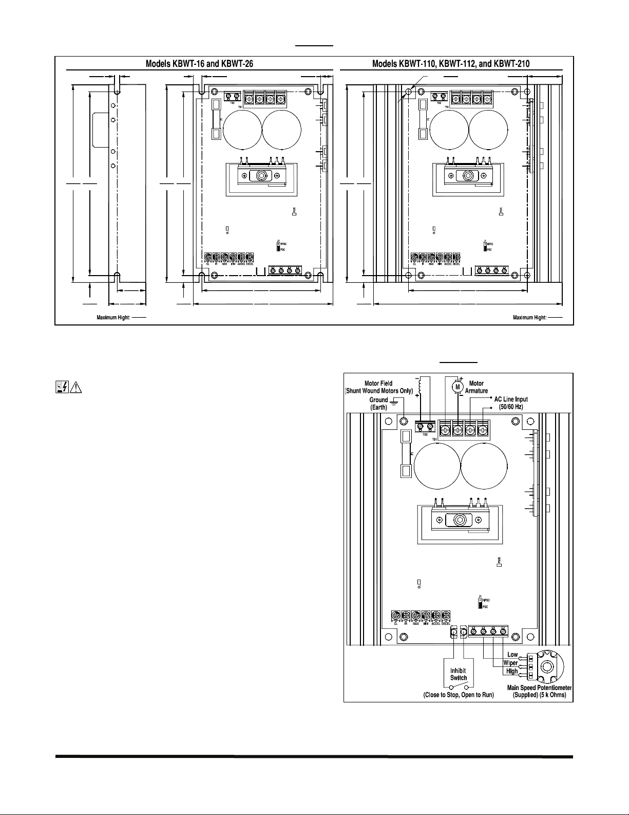
2 MOUNTING INSTRUCTIONS
The drive should be mounted on a flat surface and located in an area where it will not be exposed to
contaminants such as water, metal chips, solvents, or excessive vibration. When mounting the drive in an
enclosure, the enclosure should be large enough to allow proper heat dissipation so that the ambient temperature
does not exceed 40 °C (104 °F) at full rating. See Figure 1, on page 3.
KBWT Series Installation and Operation Instructions (A40130) – Rev. B00 – 5/29/2013
Page 2 of 7
Page 3
MECHANICAL SPECIFICATIONS (INCH / mm)
FIGURE 1
7.00
178
6X Ø
6.50
165
0.25
6.35
0.19
4.83
1.125
28.6
1.325
33.7
2.00
50.8
7.00
178
0.305
7.75
F+ F− A+ A− L1 L2
6.50
165
I1I2
4.25
108
0.25
2X
6.35
5.00
127
V+ P1 P2 P3
TB3
0.445
11.3
7.00
178
6.50
165
0.25
2X
6.35
0.20
4X Ø
5.08
F+ F− A+ A− L1 L2
I1I2
4.25
108
6.75
171
V+ P1 P2 P3
1.25
2X
31.8
TB3
3.25
82.6
3 ELECTRICAL CONNECTIONS
See Figure 2 for the connections to the drive.
GENERAL CONNECTION DIAGRAM AND DRIVE LAYOUT
FIGURE 2
WARNING! HIGH VOLTAGE! The Safety Warning,
on page 7, must be read and understood before using
the drive. Disconnect the main power before making
F+ F− A+ A− L1 L2
connections to the drive. To avoid electric shock, be
sure to properly ground the drive.
3.1 AC Line Input and Ground: Connect the AC line input
to TB1 Terminals L1 and L2. Connect the chassis to earth
ground. Be sure the AC Line voltage corresponds to the drive
voltage rating, as shown in Table 2, on page 2.
3.2 AC Line Input Fusing: The drive does not contain AC
Line fuses. Most electrical codes require that each
ungrounded conductor contain circuit protection. Do not fuse
neutral or ground connections. It is recommended to install a
fuse (Littelfuse 326, Buss ABC, or equivalent) or a circuit
breaker (Square D QOU or equivalent) in series with each
ungrounded conductor. For the recommended fuse or circuit
breaker rating, see Table 2, on page 2.
3.3 Motor Armature: Connect the motor armature to TB1
I1I2
TB3
V+ P1 P2 P3
Terminals A+ and A-. Be sure the motor voltage corresponds
to the drive output voltage rating, as shown in Table 2, on
page 2.
3.4 Armature Fuse: Models KBWT-16, 26 contain a 10 Amp fuse, Models KBWT-110, 210 contain a 15 Amp
fuse, and Model KBWT-112 contains a 20 Amp fuse. The fuse should be rated 1.5 times the full load rating of
the motor. See Table 2, on page 2.
KBWT Series Installation and Operation Instructions (A40130) – Rev. B00 – 5/29/2013
Page 3 of 7
Page 4

3.5 Motor Field (Shunt Wound Motors Only): Connect the motor field as described in Sections 3.5.1 and 3.5.2.
A
r
FIGURE 3
FULL VOLTAGE FIELD
F+ F− A+ A− L1 L2
TABLE 3
FIELD CONNECTION (SHUNT WOUND MOTORS ONLY)
Model
KBWT-16, 110, 112 115 0 – 90
KBWT-26, 210 208/230
*Step-down operation.
AC Line
Input Voltage
(Volts AC)
Armature
Voltage
(Volts DC)
0 – 180 200 F+ and F-
0 – 90* 100 F+ and L1
Field Voltage
(Volts DC) Terminals
100 F+ and F-
50 F+ and L1
FIGURE 4
HALF VOLTAGE FIELD
F+ F− A+ A− L1 L2
M
Notes: 1. Do not use field terminals for any purpose other than to power the field of a shunt wound motor. 2. Do
not connect motor armature to the field terminals. 3. Shunt wound motors may be damaged if the field remains
energized without armature rotation for an extended period of time.
3.5.1 Full Voltage Field: For 90 Volt DC motors with 100 Volt DC field and 180 Volt DC motors with 200 Volt DC
field. Connect the field positive (+) lead to TB2 Terminal F+ and the field negative lead (-) to TB2 Terminal F-, as
shown in Figure 3 and Table 3, above.
3.5.2 Half Voltage Field: For 90 Volt DC motors with 50 Volt DC field and 180 Volt DC motors with 100 Volt DC
field. Connect the field positive lead (+) to TB2 Terminal F+ and the field negative lead (-) to TB1 Terminal L1, as
shown in Figure 4 and Table 3, above.
3.6 Inhibit Switch or Contact: The drive can be electronically stopped and started with
an Inhibit switch or contact connected to TB3 Terminals I1 and I2. When the switch or
FIGURE 5
INHIBIT
contact is closed, the drive motor will coast to stop. When the switch or contact is opened,
the motor will run at the Main Speed Potentiometer or signal input setting. See Figure 5.
I1I2
3.7 Signal Input: The drive can be operated with a 5 kΩ Main Speed Potentiometer
(supplied), an isolated 0 – 5 Volt DC analog signal, or an isolated Pulse Width Modulated
(PWM) signal from a microprocessor.
Note: If an isolated signal is not available, an optional signal isolator must be installed (KBSI-240D
(Part No. 9431) or equivalent).
3.7.1 Main Speed Potentiometer:
Connect the potentiometer low side
to Terminal P1, the wiper to
Terminal P2, and the high side to
Terminal P3. See Figure 6.
3.7.2 Voltage Following Signal:
An isolated 0 – 5 Volt DC analog
voltage signal can be used to
control motor speed. Connect the
isolated voltage signal positive (+)
lead to Terminal P2 and the
negative (-) to Terminal P1. See
Figure 7.
3.7.3 Microprocessor Signal:
n isolated PWM signal from a
microprocessor can be used to
control motor speed. The
output frequency should be 200
Hz or higher and should be
derived from an optocouple
with a transistor or operational
amplifier signal output. See
Figure 8.
MAIN SPEED POTENTIOMETER
FIGURE 6
TB3
V+ P1 P2 P3
FIGURE 7
VOLTAGE FOLLOWING SIGNAL INPUT
TB3
V+ P1 P2 P3
+
FIGURE 8
MICROPROCESSOR SIGNAL INPUT
TB3
V+ P1 P2 P3
KBWT Series Installation and Operation Instructions (A40130) – Rev. B00 – 5/29/2013
Page 4 of 7
Page 5

4 SELECTABLE JUMPER J1
The drive contains a Potentiometer Safety Circuit (PSC). When power is applied to
the drive the signal input must first be set to zero: the Main Speed Potentiometer
must be set fully counterclockwise, or the analog signal must be set to 0 Volts DC,
FIGURE 9
JUMPER JI SETTINGS
Jumper J1 Set to
"PSC" Position
(Factory setting)
Jumper J1 Set to
"NPSC" Position
or the PWM signal must be set to 0 Volts DC. Then increase the signal to the
desired setting to control motor speed.
Jumper J1 is factory set to the "PSC" position, to enable the Potentiometer Safety Circuit. To disable the
Potentiometer Safety Circuit, set Jumper J1 to the "NPSC" position. See Figure 9. See Figure 2, on page 3, for
the location of Jumper J1.
5 DIAGNOSTIC INDICATORS
Two diagnostic LEDs are provided to indicate the drive's operational status. See Figure 2, on page 3, for the
location of the LEDs.
5.1 Power ON (PWR): The PWR LED will illuminate green when AC line is applied to the drive.
5.2 Overload (OL): When the motor is loaded to the Current Limit (CL) set point (established by the CL Trimpot
setting), the OL LED will illuminate red. If the drive is allowed to stay in CL and then "times out" in Timed Current
Limit (TCL), the OL LED will remain illuminated until the drive is restarted (either by an On/Off AC Line Switch or
with the Inhibit Switch). If the OL LED remains illuminated during normal drive operation, a fault condition may
exist. On cyclical loads, it may be normal for the CL LED to momentarily flash.
6 ADJUSTABLE TRIMPOTS
The drive contains trimpots which have been factory set for most applications. Figure 2, on page 3, illustrates the
location of the trimpots and their approximate factory settings. Some applications may require readjustment of the
trimpots in order to tailor the drive for a specific requirement. See Figures 10 – 15, for the trimpot ranges.
WARNING! If possible, do not adjust trimpots with the main power applied. If adjustments are
made with the main power applied, an isolated adjustment tool must be used and safety glasses must be
worn. High voltage exists in this control. Electrocution can result if caution is not exercised. The Safety
Warning, on page 7, must be read and understood before proceeding.
FIGURE 10
CL TRIMPOT
RANGE
(% FULL LOAD)
150
2000
FIGURE 11
IR TRIMPOT
RANGE
(VOLTS DC)
3, 6
150
FIGURE 12
MAX TRIMPOT
RANGE
(% BASE SPEED)
50
100
FIGURE 13
MIN TRIMPOT
RANGE
(% BASE SPEED)
300
FIGURE 14
ACCEL TRIMPOT
RANGE
(SECONDS)
2
120.2
FIGURE 15
DECEL TRIMPOT
RANGE
(SECONDS)
2
120.2
6.1 Current Limit Trimpot (CL): The CL Trimpot sets the current limit (overload), which limits the maximum
current (torque) to the motor. The CL also limits the AC line inrush current to a safe level during startup. The CL
Trimpot is factory set to 1.5 times the full load rating of the drive. To increase the current limit, rotate the CL
Trimpot clockwise (do not exceed 2 times motor current rating (maximum clockwise position)). To decrease
the current limit, rotate the CL Trimpot counterclockwise. See Figure 10, above.
Note: On cyclical loads, it may be normal for the CL LED to momentarily flash.
KBWT Series Installation and Operation Instructions (A40130) – Rev. B00 – 5/29/2013
Page 5 of 7
Page 6

To Recalibrate the CL Trimpot:
1 Disconnect the AC power and wire a DC ammeter in series with either motor armature lead.
Note: If only an AC ammeter is available, wire it in series with either AC line input lead.
2 Set the Main Speed Potentiometer to approximately 30 – 50 % clockwise position.
3 Set the CL Trimpot fully counterclockwise. The CL LED will illuminate red.
4 Lock the motor shaft (be sure the CL Trimpot is set fully counterclockwise).
5 Apply power and rotate the CL Trimpot clockwise until the desired current reading is observed on the DC
ammeter. Factory Current Limit setting is 1.5 times the full load rating of the motor (with a DC ammeter wired
in series with the motor armature). If using an AC ammeter wired in the AC line input, the factory Current Limit
setting will read 0.75 times the full load rating of the motor. Do not exceed 2 times motor current rating
(maximum clockwise position).
Note: Steps 4 and 5 must be completed within 3 seconds or the Timed Current Limit (TCL) will trip the drive. If the
drive trips in TCL the drive must be restarted (either with the On/Off AC Line Switch or the Inhibit Switch).
Warning! Do not leave motor shaft locked for more than 2 – 3 seconds or motor damage may result.
6.2 IR Compensation Trimpot (IR): The IR Trimpot sets the amount of compensating voltage required to keep
the motor speed constant under changing loads. If the load does not vary substantially, the IR Trimpot may be set
to a minimum level (approximately 1/4 of full clockwise rotation). The IR Trimpot is factory set to provide 6 Volts of
compensation for Models KBWT-16, 26 and 3 Volts of compensation for Models KBWT-110, 112, 210.
To increase the amount of compensating voltage, rotate the IR Trimpot clockwise. To decrease the amount of
compensating voltage, rotate the IR Trimpot counterclockwise. See Figure 11, on page 5.
Note: Excessive IR Compensation will cause the motor to become unstable, which causes cogging.
To Recalibrate the IR Trimpot:
1 Set the IR Trimpot to approximately 25 % rotation.
2 Run the motor unloaded at approximately 1/3 speed and record the RPMs.
3 Run the motor with the maximum load and adjust the IR Trimpot so that the motor speed under load equals
the unloaded speed recorded in step 2.
4 Remove the load and recheck the RPMs.
5 If the unloaded RPM has changed, repeat steps 2 – 4 for more exact regulation. The control is now
compensated to provide minimal speed change due to changing loads.
6.3 Maximum Speed Trimpot (MAX): The MAX Trimpot sets the maximum speed of the motor when the Main
Speed Potentiometer is set fully clockwise. The MAX Trimpot is factory set to 100% of base motor speed.
To increase the maximum speed, rotate the MAX Trimpot clockwise. To decrease the maximum speed, rotate the
MAX Trimpot counterclockwise. See Figure 12, on page 5.
Caution! Do not set the maximum speed above the rated motor RPM since unstable motor operation may occur.
6.4 Minimum Speed Trimpot (MIN): The MIN Trimpot sets the minimum speed of the motor when the Main
Speed Potentiometer is set fully counterclockwise. The MIN Trimpot is factory set to 0% of base motor speed.
To increase the minimum speed, rotate the MIN Trimpot clockwise. To decrease the minimum speed, rotate the
MIN Trimpot counterclockwise. See Figure 13, on page 5.
6.5 Acceleration Trimpot (ACCEL): The ACCEL Trimpot is provided to allow for a smooth start over an
adjustable time period each time the AC power is applied or the Main Speed Potentiometer is adjusted to a higher
speed. The ACCEL Trimpot is factory set to 2 seconds, which is the amount of time it will take for the motor to
accelerate from zero speed to full speed. To increase the acceleration time, rotate the ACCEL Trimpot clockwise.
To decrease the acceleration time, rotate the ACCEL Trimpot counterclockwise. See Figure 14, on page 5.
KBWT Series Installation and Operation Instructions (A40130) – Rev. B00 – 5/29/2013
Page 6 of 7
Page 7

6.6 Deceleration Trimpot (DECEL): The DECEL Trimpot controls the amount of ramp-down time when the
Main Speed Potentiometer is adjusted to a lower speed. The DECEL Trimpot is factory set to 2 seconds, which is
the amount of time it will take for the motor to decelerate from full speed to zero speed. To increase the
deceleration time, rotate the DECEL Trimpot clockwise. To decrease the acceleration time, rotate the DECEL
Trimpot counterclockwise. See Figure 15, on page 5.
Note: The deceleration time cannot be made less than the natural coast time of the motor and actual load.
7 OPERATION
WARNING! The Safety Warning, on page 1, must be read and understood before attempting to
operate this drive or severe injury or electrocution can result.
After the drive has been set up properly and wiring has been completed, the start-up procedure can begin. If the
AC power has been properly connected to the drive, the PWR LED should illuminate green. Before starting, be
sure that the Main speed Potentiometer is in the minimum position (fully counterclockwise). To start the drive,
rotate the potentiometer clockwise. The motor should begin to rotate.
Note: If the motor rotates in the incorrect direction, it will be necessary to disconnect the main AC power and
reverse the armature leads.
SAFETY WARNING! – PLEASE READ CAREFULLY!
This product must be installed and serviced by a qualified technician, electrician, or electrical maintenance
person familiar with its operation and the hazards involved. Proper installation, which includes electrical
connections, fusing or other current protection, and grounding, can reduce the chance of electrical shocks,
and/or fires, in this product or products used with this product, such as electric motors, switches, coils, solenoids,
and/or relays. Do not use this drive in an explosion-proof application. Eye protection must be worn and insulated
adjustment tools must be used when working with drive under power. This product is constructed of materials
(plastics, metals, carbon, silicon, etc.) which may be a potential hazard. Proper shielding, grounding, and filtering
of this product can reduce the emission of radio frequency interference (RFI) which may adversely affect
sensitive electronic equipment. It is the responsibility of the equipment manufacturer and individual installer to
supply this Safety Warning to the ultimate end user of this product. (SW 8/2012)
The drive contains electronic Start/Stop circuits, which can be used to start and stop the drive. However, these
circuits are never to be used as safety disconnects since they are not fail-safe. Use only the AC Line for this
purpose.
Be sure to read and follow all instructions carefully. Fire and/or electrocution can result due to improper use of this
product.
This product complies with all CE directives pertinent at the time of manufacture. Contact our Sales
Department for Declaration of Conformity. Installation of a CE approved RFI filter (KBRF-200A (Part No. 9945),
or equivalent) is required. Additional shielded motor cable and/or shielded AC Line cables may be required along
with a signal isolator (KBSI-240D (Part No. 9431) or equivalent).
KBWT Series Installation and Operation Instructions (A40130) – Rev. B00 – 5/29/2013
Page 7 of 7
 Loading...