

Page 1
KM 120/150 R G
KM 120/150 R D
KM 120/150 R LPG
59637740 09/14
Page 2

2
Page 3

Please read and comply with
these original instructions prior
to the initial operation of your appliance and
store them for later use or subsequent owners.
Before first start-up it is definitely necessary to read the safety indications no.
5.956-250!
Contents
Appliance description . . . . . EN . . . 1
Safety instructions . . . . . . . EN . . . 1
General notes . . . . . . . .
Symbols on the machine
Symbols in the operating in-
structions. . . . . . . . . . . . EN
Safety Guidelines for liquified gas vehicles (only KM
120/150 R LPG) . . . . . . EN
Function . . . . . . . . . . . . . . . EN . . . 3
Proper use . . . . . . . . . . . . . EN . . . 3
Suitable surfaces. . . . . .
Environmental protection . . EN . . . 3
Operating and Functional Ele-
ments . . . . . . . . . . . . . . . . . EN . . . 4
Machines without driver cab-
in . . . . . . . . . . . . . . . . . . EN
Machines with driver cabin
Colour coding . . . . . . . .
Opening/closing and secur-
ing cover . . . . . . . . . . . . EN
Operator console. . . . . .
Before Startup. . . . . . . . . . . EN . . . 7
Unloading . . . . . . . . . . .
Moving sweeper without en-
gaging self-propulsion . . EN
Moving sweeper by engag-
ing self-propulsion . . . . . EN
Start up . . . . . . . . . . . . . . . . EN . . . 7
General notes . . . . . . . .
Refuelling (only KM 120/150
R G and R D) . . . . . . . . EN
Connect/ change gas cylin-
der (only KM 120/150 R
LPG) . . . . . . . . . . . . . . . EN
Inspection and maintenance
work. . . . . . . . . . . . . . . . EN
Operation . . . . . . . . . . . . . . EN . . . 8
Adjusting driver's seat . .
Adjusting the external mirror
(only KM 120/150 without
driver cabin) . . . . . . . . . EN
Switching on/off the wipers
(only KM 120/150 without
driver cabin) . . . . . . . . . EN
Programme selection . .
Starting the machine . . .
Drive the machine . . . . .
Sweeping mode . . . . . .
Emptying waste container
Turn off the appliance . .
Shutdown . . . . . . . . . . . . . . EN . . . 9
Close fuel tap (only KM 120/
150 R G and R D) . . . . . EN
Close gas supply (only KM
120/150 R LPG) . . . . . . EN
Transport. . . . . . . . . . . . . . . EN . . 10
Storing the device . . . . . . . . EN . . 10
EN
EN
EN
EN
EN
EN
EN
EN
EN
EN
EN
EN
EN
EN
EN
. . . 1
. . . 2
. . . 2
. . . 2
. . . 3
. . . 4
. . . 4
. . . 4
. . . 5
. . . 6
. . . 7
. . . 7
. . . 7
. . . 7
. . . 7
. . . 7
. . . 8
. . . 8
. . . 8
. . . 8
. . . 8
. . . 8
. . . 8
. . . 8
. . . 9
. . . 9
. . 10
. . 10
Maintenance and care . . . . . EN . 10
General notes . . . . . . . .
EN
. 10
Cleaning the inside of the
machine . . . . . . . . . . . . . EN
. 10
External cleaning of the ap-
EN
EN
. 10
. 10
. .11
pliance . . . . . . . . . . . . . . EN
Maintenance intervals . .
Maintenance Works . . . .
Troubleshooting. . . . . . . . . . EN . 16
Technical specifications . . . . EN . 17
Accessories . . . . . . . . . . . . . EN . 18
Installation set suction hose
EN
. 18
EC Declaration of Conformity EN . 18
Warranty . . . . . . . . . . . . . . . EN . 18
Appliance description
– KM 120/150 R G = Petrol engine
– KM 120/150 R D = diesel engine
– KM 120/150 R LPG = gas engine
Safety instructions
– The machine (without driver cabin) has
been approved for use on surfaces with
gradients of up to 18%.
– The machine (with driver cabin) has
been approved for use on surfaces with
gradients of up to 10%.
General notes
Your sales outlet should be informed about
any transit damage noted when unpacking
the product.
– Warning and information plates on the
machine provide important directions
for safe operation.
– In addition to the information contained
in the operating instructions, all statutory safety and accident prevention regulations must be observed.
Drive mode
Danger
Risk of injury!
Danger of tipping if gradient is too high.
– Drive up the slopes only with max. 18%
gradient (without driver cabin) or 10%
(with driver cabin).
Danger of tipping when driving round
bends at high speed.
– Drive slowly when cornering.
Danger of tipping on unstable ground.
– Only use the machine on sound surfac-
es.
Danger of tipping with excessive sideways
tilt.
– The gradient perpendicular to the direc-
tion of travel should not exceed 10%.
– It is important to follow all safety instruc-
tions, rules and regulations applicable
for driving motor vehicles.
– The operator must use the appliance
properly. He must consider the local
conditions and must pay attention to
third parties, in particular children, when
working with the appliance.
– The appliance may only be used by per-
sons who have been instructed in han-
dling the appliance or have proven
qualification and expertise in operating
the appliance or have been explicitly
assigned the task of handling the appliance.
– The appliance must not be operated by
children, young persons or persons
who have not been instructed accordingly.
– It is strictly prohibited to take co-pas-
sengers.
– Ride-on appliances may only be started
after the operator has occupied the driver's seat.
Please remove the ignition key, when
not in use, to avoid unauthorised use of
the appliance.
Never leave the machine unattended
so long as the engine is running. The
operator may leave the appliance only
when the engine has come to a standstill, the appliance has been protected
against accidental movement, if necessary, by applying the immobilization
brake and the ignition key has been removed.
Appliances with combustion engine
Danger
Risk of injury!
– Do not close the exhaust.
– Do not bend over the exhaust or touch
it (risk of burns).
– Do not touch the drive motor (risk of
burns).
– Only KM 120/150 R LPG: Ensure that
there is adequate ventilation or provision for diverting the exhaust gas while
operating the appliance in closed
rooms (risk of poisoning).
– Exhaust gases are poisonous and haz-
ardous to health, do not inhale them.
– The engine requires approx. 3-4 sec-
onds to come to a standstill once it has
been switched off. During this time, stay
well clear of the working area.
Machines with driver cabin
Note
The driver cabin only provides protection
against weather; it is not a safety roof or a
lock against overrolling!
Danger
The plastic sheet doors of the driver cabin
have ventilation slots. Always leave these
open to ensure adequate ventilation.
Risk of hearing impairment. Always use
proper ear-protection
aids while working with
the appliance.
Accessories and Spare Parts
– Only use accessories and spare parts
which have been approved by the manufacturer. The exclusive use of original
accessories and original spare parts
- 1
3EN
Page 4

ensures that the appliance can be operated safely and trouble free.
– At the end of the operating instructions
you will find a selected list of spare
parts that are often required.
– For additional information about spare
parts, please go to the Service section
at www.kaercher.com.
Symbols on the machine
Risk of burns on account of hot surfaces!
Allow the exhaust to
cool down sufficiently
before starting work on
the machine.
Symbols in the operating instruc-
tions
DANGER
Immediate danger that can cause severe
injury or even death.
몇 WARNING
Possible hazardous situation that could
lead to severe injury or even death.
CAUTION
Possible hazardous situation that could
lead to mild injury to persons or damage to
property.
Safety Guidelines for liquified gas
vehicles (only KM 120/150 R LPG)
Hauptverband der gewerblichen Berufsgenossenschaften e.V. (HVBG / Germany). Liquified gases (propellants) are
butane and propane or a mixture of butane/
propane. They are available in special cylinders. The operating pressure of these
gases depends on the outside temperature.
Danger
Risk of explosion! Do not handle liquified
gas like petrol. Petrol evaporates slowly,
liquified gas immediately turns into gas.
The risk of gas spreading in the room and
getting ignited is thus higher in case of liquefied gas than in petrol.
Danger
Risk of injury! Use only liquefied gas cylinders with propellant filled according to DIN
51622 of A or B quality, depending on the
surrounding temperature.
CAUTION
Use of cooking gas is strictly prohibited. For
the gas engine, use only liquid gas mixtures of propane/ butane or their mixtures
where the mixing ratio lies between 90/10
to 30/70. On account of better cold start behaviour even at low outside sub-zero temperatures (below 0° C / 32 °F) always
prefer a mixture with a higher propane
share because evaporation takes place
even at low temperatures.
Liabilities of the factory management
and the employee
– All persons handling liquid gases are li-
able to acquaint themselves with the
special properties of the liquefied gases
for hazard-free handling of operations.
The current documentation is always to
be kept with the sweeper.
Maintenance by expert
– Propellant-operated units are to be
checked at regular intervals, at least
once a year, by an expert against leaks
(according to BGG 936) and ensure
that the unit is functioning properly.
– The inspection must be certified and
documented. The inspection guidelines
are § 33 and § 37 UVV (occupation accident prevention regulations) "Use of
liquid gas" (BGV D34).
– General applicable regulations are the
guidelines for inspecting vehicles
whose engines are driven by liquefied
gases of the Federal Transportation
Minister.
Commissioning/Operations
– Gas must always be drawn only from
one cylinder. Drawing gas from multiple
cylinders simultaneously can cause liquid gas from one cylinder flowing into
the other. This causes the over-filled
cylinder to be subjected to an unpermitted excess pressure when the cylinder
valve is closed later (refer B.1 of these
guidelines).
– Ensure the correct positioning of the
cylinder with the "top" marking while
connecting a full cylinder (the connection screw points vertically upward).
Perform the replacement of the gas cylinder carefully. During assembly and disassembly, the gas outlet nozzle of the
cylinder valve must be sealed by means of
a cap nut that is tightened using a wrench.
– Discontinue the use of leaky gas cylin-
ders. Such cylinders are to be emptied
by slowly letting out the gas in open
spaces by conforming to all safety regulations and are to be indicated as
leaky. Also inform the issuing company
or its representative (the filling-station
attendant) in writing about the damage
to the cylinder while delivering or receiving the cylinders.
– Before connecting the gas cylinder,
check that its connection neck is in a
proper state.
– After connecting the cylinder, regularly
check that it is not leaky by using a
foaming agent.
– Open the valves slowly. Do not use
hammers to open and close the cylinders.
– Use only dry fire extinguishers (with
carbonic acid gas) in case of fire
caused by liquefied gases.
– The entire LPG unit must be continu-
ously checked to ensure that there are
no leaks and the unit is functioning
properly. Using the vehicle with a leaky
gas unit is strictly prohibited.
– First close the cylinder valve before
loosening the pipe or tube connection.
Unscrew and loosen the connection nut
of the gas cylinder slowly because otherwise the gas under pressure in the
tube will flow out instantly.
– If the gas is refilled from a larger tank,
then ask the sales agent of the LPG
about the important regulations to be
followed.
Danger
Risk of injury!
– LPG in a liquid state can cause frost
bites on bare skin.
– After disconnecting the cylinder, tighten
the closing nut firmly on the connecting
threading of the cylinder.
– Use soap water or some such foaming
agent to check whether the cylinder is
leaking. The use of open flames to illuminate the LPG unit is strictly prohibited.
– Follow the manufacturer's installation
specifications while changing individual
parts of the LPG unit. Close all cylinder
and locking valves while doing so.
– Regularly check the status of the elec-
trical unit of the LPG vehicles . Sparks
can cause explosions if the gas-carrying parts of the unit are leaky.
– If a LPG-driven vehicle has been idling
for a long time, then first ventilate the
4 EN
- 2
Page 5
setting room before commissioning the
vehicle or its electrical unit.
– Immediately inform the trade associa-
tion and the concerned trade supervisory authority about accidents with gas
cylinders or LPG units. Store the damaged parts carefully until all investigations have been completed.
In the installation and storage rooms as
well as the workshops
– Propellants or LPG cylinders must al-
ways be stored according to the regulations of TRF 1996 (Technical
Regulations for Liquid Gases, refer DA
to BGV D34, Appendix 4).
– Always store the gas cylinders in a ver-
tical position. Use of open flames and
smoking at the installation site of the
cylinders and during repairs is strictly
prohibited. Protect the stored cylinders
against unauthorised access. Close all
empty cylinders properly.
– Close the cylinder and main locking
valves immediately when you switch off
the vehicle.
– Follow the regulations for garages and
the construction guidelines of the respective State about the location and
structure of the parking areas for LPGdriven vehicles.
– Gas cylinders are to be stored in sepa-
rate rooms away from the parking areas
(refer DA to BGV D34, Appendix 2).
– The electrical hand-held lamps used in
the rooms are to be equipped with
closed, sealed case and a strong protection cover.
– Close all cylinder and main valves be-
fore working in repair workshops and
protect the gas cylinders against effect
of external heat.
– A responsible person must check that
all valves, especially the cylinder
valves, are closed during operational
breaks and before closing the factory.
Do not carry out any jobs involving fire such as cutting and welding jobs - in the
vicinity of the gas cylinders. Do not
store gas cylinders, not even empty
ones, in the workshops.
– The parking and storage rooms and the
repair workshops must be ventilated
properly. Please note that liquefied gases are heavier than atmospheric air.
They get collected on the floor, in recesses and other holes in the floors and
form a gas-air mixture that can lead to
explosions.
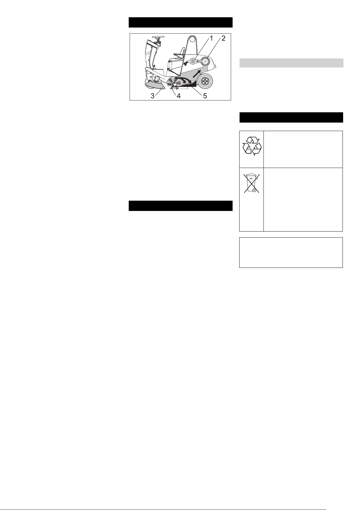
Function
Figure 1
The sweeper operates using the overthrow
principle.
– The side brushes (3) clean the corners
and edges of the surface, moving dirt
and debris into the path of the roller
brush.
– The rotating roller brush (4) moves the
dirt and debris directly into the waste
container (5).
– The dust raised in the container is sep-
arated by the dust filter (2) and the filtered clean air is drawn off by the
suction fan (1).
Proper use
Use this appliance only as directed in these
operating instructions.
The machine with working equipment
must be checked to ensure that it is in
proper working order and is operating
safely prior to use. Otherwise, the appliance must not be used.
– This sweeper has been designed to
sweep dirt and debris from outdoor surfaces.
– Only KM 120/150 R LPG: This sweeper
is also suitable for sweeping dirty floors
in closed spaces provided the same are
ventilated adequately.
– The machine can only be used on pub-
lic highways with the StVZO extension
kit.
– The machine is not suitable for vacuum-
ing dust which endangers health.
– The machine may not be modified.
– Never vacuum up explosive liquids,
combustible gases or undiluted acids
and solvents. This includes petrol, paint
thinner or heating oil which can generate explosive fumes or mixtures upon
contact with the suction air. Acetone,
undiluted acids and solvents must also
be avoided as they can harm the materials on the machine.
– Do not sweep/vacuum up any burning
or glowing objects.
– The machine is only suitable for use on
the types of surfaces specified in the
operating instructions.
– The machine may only be operated on
the surfaces approved by the company
or its authorised representatives.
– The machine may not be used or stored
in hazardous areas. It is not allowed to
use the appliance in hazardous locations.
– The following applies in general: Keep
highly-flammable substances away
from the appliance (danger of explosion/fire).
Suitable surfaces
– Asphalt
– Industrial floor
– Screed
– Concrete
– Paving stones
Environmental protection
The packaging material can be
recycled. Please do not throw
the packaging material into
household waste; please send
it for recycling.
Old appliances contain valuable materials that can be recycled; these should be sent for
recycling. Batteries, oil, and
similar substances must not
enter the environment. Please
dispose of your old appliances
using appropriate collection
systems.
Please do not release engine oil, fuel oil,
diesel and petrol into the environment
Protect the ground and dispose of used
oil in an environmentally-clean manner.
Notes about the ingredients (REACH)
You will find current information about the
ingredients at:
www.kaercher.com/REACH
- 3
5EN
Page 6
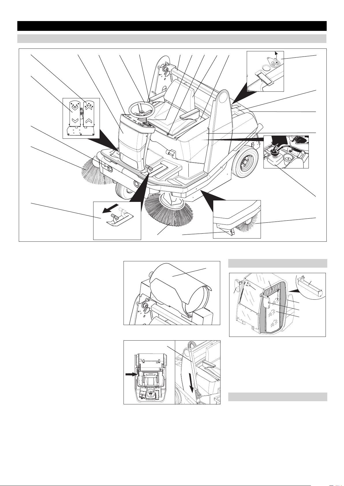
Operating and Functional Elements
Machines without driver cabin
11
5
4321 1213141516
17
6
18
19
7
20
8
21
22
Figure 2a
1 Operator control unit for waste contain-
er and parking brake
2 Steering wheel
3 Operator console
4 Fuses (behind front panel)
5 Accelerator pedal, forwards
6 Accelerator pedal, reverse
7 Lights
8 Right side brush
9 Left side brush
10 Bulk waste flap
11 Pedal for raising/lowering bulk waste
flap
12 Lift/tilt emptying mechanism
13 Lever for steering wheel adjustment
14 Lever for seat adjustment
15 Seat (with seat contact mat)
16 Seat bracket
17 Wet/dry flap
18 Filter case
19 Waste container
20 Cover
21 Tank
22 Roller brush
23 Gas cylinder (only KM 120/150 R LPG)
24 Installation set suction hose (option)
Figure 2b
Figure 2c
910
24
23
Machines with driver cabin
72
4
3
1
5
6
Figure 2d
1 Driver cabin (optional)
2 Tank
3 Turn on/off the wipers
4 Right exterior mirror
5 Left exterior mirror
6 Plastic sheet doors
7 Ventilation slots
Colour coding
The operating elements for the cleaning
process are yellow.
The controls for the maintenance and
service are light gray.
6 EN
- 4
Page 7
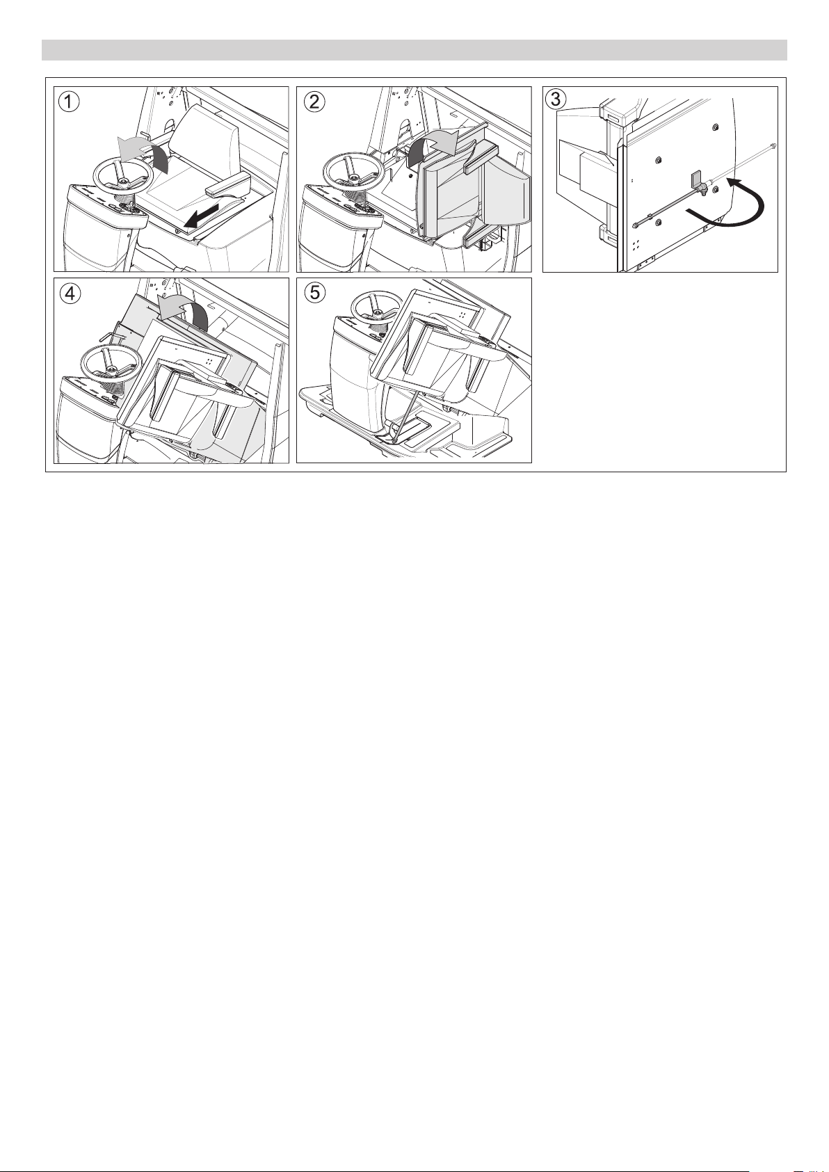
Opening/closing and securing cover
Figure 3
Danger
Risk of injury! When open, the cover must
be propped up using the retaining rod.
Figure 1
Operate steering wheel adjustment le-
ver and fold steering wheel forwards.
Operate seat adjustment lever and
slide seat forwards.
Figure 2
Fold seat bracket to the side.
Figure 3
Fold out retaining rod.
(only 120/150 KM without driver cabin)
Figure 4
Fold cover forwards.
Figure 5
Insert retaining rod into the recess next
to the bulk waste flap pedal.
(only 120/150 KM without driver cabin)
Follow this sequence in reverse order to
close the cover.
- 5
7EN
Page 8

Operator console
16
12
13
14
3
4
567
8
1
9
2
10
11
15
Figure 4
1 Programme switch
2 Switch two-hand operations Lift/tilt
emptying mechanism
3 Button for filter shaker system
4 Button for power-operating mode
5 Indicator lamp for power-operating
mode
6 Elapsed-time counter with reset button
7 Switch for working lamp
8 Horn switch
9 Raise/lower waste container
10 Tilt waste container outwards/inwards
11 Parking brake
12 Ignition lock
13 Charge indicator lamp (only KM 120/
150 R D and LPG)
14 Choke (only KM 120/150 R G)
15 Remote button (only KM 120/150 R
LPG)
16 Wet cleaning switch, installation set
suction hose (option)
8 EN
- 6
Page 9

Before Startup
Unloading
몇
Warning
Do not use a forklift truck to unload the machine as this may damage it.
To unload the machine, proceed as follows:
Cut plastic packing belt and remove foil.
Connect battery (see section on Care
and maintenance)
Remove the elastic tape fasteners at
the stop points.
Four indicated floor boards of the pallet
are fastened with screws. Unscrew
these boards.
Place the boards on the edge of the pal-
let. Place the boards in such a way that
they lie in front of the four wheels of the
machine. Fasten the boards with screws.
Slide the four support beams included
in the packaging under the ramp.
Remove the wooden blocks used for ar-
resting the wheels and slide them under
the ramp.
The machine can be moved in 2 ways:
(1) By pushing it (see Moving sweeper
without engaging self-propulsion).
(2) By driving it (see Moving sweeper by
engaging self-propulsion).
Moving sweeper without engaging
self-propulsion
Danger
Risk of injury! Before engaging the freewheel operation, the machine must be secured to prevent it rolling away.
Lock parking brake.
Open cover and secure it (Diag. 3).
Moving sweeper by engaging self-
propulsion
Unhook the free wheel lever.
The travel drive is now ready for operation.
Close cover.
Release parking brake.
The appliance can now be driven.
Start up
General notes
Park the sweeper on an even surface.
Remove ignition key.
Lock parking brake.
Refuelling (only KM 120/150 R G and
R D)
Refuelling the machine
Danger
Risk of explosion!
– Only use the fuels specified in the Op-
erations Manual.
– Do not refuel the machine in enclosed
spaces.
– Smoking and naked flames are strictly
prohibited.
– Ensure that no fuel reaches the hot
open surfaces.
Switch off engine.
Only KM 120/150 without driver cabin:
Open cover and secure it (Diag. 3).
Open fuel filler cap.
Insert funnel provided.
KM 120/150 R G: Use regular unleaded
petrol.
KM 120/150 R D: Use diesel.
Fill tank to max. 1 cm below the lower
edge of the filler nozzle.
Wipe off any spilt fuel, remove funnel
and close fuel filler cap.
Only KM 120/150 without driver cabin:
Close cover.
Resetting fuel gauge
Note
After the machine is switched on, the number of operating hours is displayed for 10
seconds. The fuel gauge is then automatically displayed.
Note
The fuel gauge shows the length of time the
machine has been in operation since the
elapsed-time counter was last reset.
Press reset button (2) on the elapsed-
time counter.
Connect/ change gas cylinder (only
KM 120/150 R LPG)
몇 Warning
Only use replacement cylinders with 11 kg
contents of tested models.
Danger
Risk of injury!
– Follow safety regulations for LPG vehi-
cles.
– Formation of crusts and yellow-frothing
deposits on the gas cylinder indicate
leakiness.
– Cylinders must be changed only by in-
structed persons.
– Cylinders containing propellant gases
must not be changed in garages and
underground areas.
– Do not smoke and use uncovered light
while changing the cylinder.
– While changing cylinders, first close the
locking valve of the LPG cylinder firmly
and immediately put the protective cap
on the empty cylinder.
1
2
3
Place the cylinder in such a way that the
connection threading of the locking
valve vertically points upwards.
Close the bracket closure.
Attach safety splint.
Remove protective lid (1) from the con-
nection valve of the cylinder.
Connect the gas tube with Union nut (2)
(use 30 mm spanner).
Note
Connection has a left threading.
몇 Warning
Open the gas drawing valve (3) only after
starting the appliance (refer chapter Starting the appliance).
Engage freewheel lever in hole.
This blocks the travel drive function.
Close cover.
Release parking brake.
The machine can now be pushed.
Note
Do not move the machine for long distances without engaging self-propulsion, a
speed of 6 km/h should not be exceeded.
Note
The machine can be operated for a maximum of 3 hours on a full tank.
- 7
9EN
Page 10

Inspection and maintenance work
Check engine oil level. *
Only KM 120/150 R G and R D: Check
fill level of fuel tank. *
Only KM 120/150 R LPG: Check and
ensure that the Union nut is fixed prop-
erly on the gas tube. *
Check hydraulics fluid fill level. *
Check side brush. *
Check roller brush. *
Empty waste container.
Check tyre pressure. *
* For description, see section on Care and
maintenance.
Operation
몇 Warning
The air inlets next to the driver's seat must
not be covered. Do not store any objects
next to or behind the seat.
Adjusting driver's seat
Pull seat adjustment lever outwards.
Slide seat, release lever and lock in
place.
Check that the seat is properly locked in
position by attempting to move it back-
wards and forwards.
Adjusting the external mirror (only
KM 120/150 without driver cabin)
Adjust the left and right exterior mirror
manually.
Switching on/off the wipers (only
KM 120/150 without driver cabin)
Press the switch for windscreen washer
system.
Programme selection
3
2
1
4
5
Starting the machine
Note
The machine is equipped with a seat contact mat. If the driver's seat is vacated, the
machine is switched off.
NOTICE
Only KM 120/150 R G and R LPG: Device
starts only if the immobilising brakes are
applied (parking position).
Open fuel tap (only KM 120/150 R G and
R D)
Note
The fuel cock is supplied from the factory
open. If the machine has been out of use
for a longer period of time, open the fuel
cock.
Open cover and secure it (Diag. 3).
KM 120/150 R G:
Push lever in "ON" direction.
KM 120/150 R D:
Turn lever to position "O".
Close cover.
Open gas supply (only KM 120/150 R
LPG)
Only KM 120/150 R LPG: Press remote
switch for 5 seconds, then release it.
Turn ignition key past position 1.
If the machine starts, release the igni-
tion key.
Note
Never operate the starter motor for longer
than 10 seconds. Wait at least 10 seconds
before operating the starter motor again.
Note
Operation during winter: When starting at
temperatures below +10 °C, the parking
brake is to be applied to disengage the engine from the transmission and therefore
assist the starting process.
Drive the machine
Release parking brake.
Drive forward
Press right accelerator pedal down
slowly.
Reverse drive
Danger
Risk of injury! While reversing, ensure that
there is nobody in the way, ask them to
move if somebody is around.
Press left accelerator pedal down slowly.
Note
Driving method
– The accelerator pedal can be used to
vary the driving speed infinitely.
– Avoid pressing the pedal suddenly as
this may damage the hydraulic system.
– In the event of power loss on inclined
surfaces, slightly reduce the pressure
on the accelerator pedal.
Brakes
Release the accelerator pedal, the ma-
chine brakes automatically and stops.
Driving over obstacles
Driving over fixed obstacles which are 50
mm high or less:
Drive forwards slowly and carefully.
Driving over fixed obstacles which are
more than 50 mm high:
Only drive over these obstacles using a
suitable ramp.
Sweeping mode
1 Driving
Driving to the Place of Use.
2 Sweeping with sweep roller
Roller brush is lowered.
3 Sweeping with right side brush
Sweep roller and right side brush are
lowered.
4 Sweep using left side brush (optional)
Sweep roller and left side brush are
lowered.
5 Sweep using both brushes (optional)
Sweep roller and both brushes are low-
ered.
Open the gas drawing valve by turning
it in anti-clockwise direction.
Turning on the Appliance
Lock parking brake.
Sit on the driver's seat.
Do NOT press the accelerator pedal.
Set programme switch to step 1 (driv-
ing).
Only KM 120/150 R G: Press choke le-
ver downwards. Once the engine is running, pull choke lever back up.
10 EN
Danger
Risk of injury! If the bulk waste flap is open,
stones or gravel may be flung forwards by
the roller brush. Make sure that this does
not endanger persons, animals or objects.
몇 Warning
Do not sweep up packing strips, wire or
similar objects as this may damage the
sweeping mechanism.
몇 Warning
To avoid damaging the floor, do not continue to operate the sweeping machine in the
same position.
Note
To achieve an optimum cleaning result, the
driving speed should be adjusted to take
specific situations into account.
- 8
Page 11

Note
During operation, the waste container
should be emptied at regular intervals.
Note
When cleaning surfaces, only lower the
roller brush.
Note
Also lower side brush when cleaning along
edges.
Sweeping with roller brush (basic-operating mode)
Note
Two operating modes are possible with the
roller brush. In the basic-operating mode,
the roller brush is only subjected to a small
amount of wear and tear.
Set programme switch to step 2. Roller
brush is lowered.
Sweeping with roller brush (power-operating mode)
Note
Two operating modes are possible with the
roller brush. Power-operating mode increases cleaning performance.
Set programme switch to step 2. Roller
brush is lowered.
Press power button. Indicator lamp
lights up.
Note
The following actions reset the power button automatically:
– Press the power button again.
– Set programme switch to step 1 (driv-
ing).
– Switching off the machine.
The indicator lamp goes out and the basicoperating mode is activated.
Note
To sweep up larger items with a height of
60 mm, e.g. soft drink cans, the bulk waste
flap must be raised briefly.
Sweeping with bulk waste flap raised
Raising bulk waste flap:
Press the pedal for the bulk waste flap
forwards and keep pressed down.
To lower it, take foot off pedal.
Note
An optimum cleaning result can only be
achieved if the bulk waste flap has been
lowered completely.
Sweeping with side brushes
To sweep in edge area on right-hand side:
Set programme switch to step 3. The
right side brush and roller brush are
lowered.
To sweep in edge area on left-hand side:
Set programme switch to step 4. The
left side brush and roller brush are low-
ered.
To sweep in edge areas on right- and left-
hand side:
Set programme switch to step 5. Both
side brushes and roller brush are lowered.
Note
Roller brush and side brush start operating
automatically.
Sweeping dry floors
Close wet/dry flap on waste container.
Installation set suction hose (option):
Press wet sweeping button repeatedly.
Sweeping damp or wet floors
Open wet/dry flap on waste container.
Installation set suction hose (option):
Press wet sweeping button.
Note
This protects the filter from moisture.
Emptying waste container
Note
Wait until the automatic filter shaking process is finished and the dust has settled before you open or empty the waste
container.
Danger
Risk of injury! When emptying the waste
container, care should be taken to ensure
that no persons or animals are within its
swivelling range.
Danger
Danger of crushing. Never reach into the
rod assembly for the drainage mechanism.
Stay away from the area under the raised
container.
Danger
Danger of tipping. Place the machine on an
even surface during emptying.
Stop the machine.
Set programme switch to step 1 (driv-
ing).
Note
The container can only be tilted and emptied once a set minimum level has been
reached.
Note
A two-handed operation is required to carry
out the following steps.
1
2
3
45
Raise waste container. Press button 1
(operator console) and 2 simultaneously.
Once the required height has been
reached:
Tip waste container out. Press button 1
(operator console) and 5 simultaneously.
Tip waste container back in. Press but-
ton 1 (operator console) and 4 simultaneously.
Lower waste container. Press button 1
(operator console) and 3 simultaneously.
Note
The container can only be fully retracted if
it is tipped back into its starting position beforehand.
Turn off the appliance
Set programme switch to step 1 (driv-
ing). The side brush and roller brush are
raised.
Turn ignition key to "0" and remove it.
Lock parking brake.
Note
Once the machine has been switched off,
the dust filter is shaked automatically for
approx. 15 seconds.
Shutdown
If the sweeper is going to be out of service
for a longer time period, observe the following points:
Park the sweeper on an even surface.
Only KM 120/150 R G and R D: Fill fuel
tank and close fuel cock.
Only KM 120/150 R LPG: Close the gas
cylinder valve and remove the cylinder.
Store the gas cylinder according to the
safety regulations for LPG vehicles.
Change engine oil.
Set programme switch to step 1 (driv-
ing). The roller brush and side brushes
are raised to prevent the bristles being
damaged.
Turn ignition key to "0" and remove it.
- 9
11EN
Page 12

Only KM 120/150 R G and R LPG: Un-
screw spark plugs and pour approx.
3 cm³ of oil into the spark plug hole.
Crank the engine several times before
replacing the spark plug. Screw in the
spark plug.
Secure sweeper to prevent it rolling
away, lock parking brake.
Clean the inside and outside of the
sweeper.
Park the machine in a safe and dry
place.
Disconnect battery.
Charge battery approx. every 2 months.
Close fuel tap (only KM 120/150 R G
and R D)
Open cover and secure it (Diag. 3).
KM 120/150 R G:
Transport
CAUTION
Risk of injury and damage! Observe the
weight of the appliance when you transport
it.
몇 Warning
In general, when shipping the machine, the
freewheel lever must be engaged in the upper hole. Only once this has been done, will
the travel drive be ready for operation. The
machine must always be moved up or
down slopes by engaging self-propulsion.
Turn ignition key to "0" and remove it.
Only KM 120/150 R G and R D: Empty
tank. Draw off fuel using suitable pump.
Only KM 120/150 R LPG: Close the gas
cylinder valve and remove the cylinder.
Store the gas cylinder according to the
safety regulations for LPG vehicles.
Secure the wheels of the machine with
wheel chocks.
Secure the machine with tensioning
straps or cables.
Lock parking brake.
– Use only roller brushes/ side-brushes
that are provided with the appliance or
specified in the Operations Manual.
The use of other roller brushes/ sidebrushes can affect the safety of the appliance.
– Do not clean the appliance with a water
hose or high-pressure water jet (danger
of short circuits or other damage).
Cleaning the inside of the machine
Danger
Risk of injury! Wear dust mask and protective goggles.
Open cover and secure it (Diag. 3).
Clean machine with a cloth.
Blow through machine with com-
pressed air.
Close cover.
External cleaning of the appliance
Clean the machine with a damp cloth
which has been soaked in mild detergent.
Note
Do not use aggressive cleaning agents.
Maintenance intervals
Push lever in "OFF" direction.
KM 120/150 R D:
Turn lever to position "S".
Close cover.
Close gas supply (only KM 120/150
R LPG)
Close gas drawing valve by turning it in
clock-wise direction.
Note
Observe markings for fixing points on base
frame (chain symbols). When loading or
unloading the machine, it may only be operated on gradients of max. 18%.
Storing the device
CAUTION
Risk of injury and damage! Note the weight
of the appliance in case of storage.
Park the machine in a safe and dry place.
Maintenance and care
General notes
First switch off the appliance and re-
move the ignition key before performing
any cleaning or maintenance tasks on
the appliance, replacing parts or switching over to another function.
Pull out the battery plug or clamp the
battery while working on the electrical
unit.
– Maintenance work may only be carried
out by approved customer service outlets or experts in this field who are familiar with the respective safety
regulations.
– Mobile appliances used for commercial
purposes are subject to safety inspections according to VDE 0701.
Note
The elapsed-time counter shows the timing
of the maintenance intervals.
Maintenance by the customer
Daily maintenance:
Check engine oil level.
Check axle drive oil level.
Check tyre pressure.
Only KM 120/150 R LPG: Check gas
pipes and connecting screws.
Only KM 120/150 R LPG: Check gas fil-
ter in the screw to the gas cylinder to
see if it is dirty, clean it if required (every
time you change the cylinder).
Check function of all operator control el-
ements.
Weekly maintenance:
Check leakiness of fuel or gas connec-
tions.
Check return-line filter for sweeping
system.
Check air filter.
Check oil level of sweeper hydraulics.
Check hydraulic lines for leaks.
Check moving parts for freedom of
movement.
Check the sealing strips in the sweep-
ing area for position and wear.
Maintenance to be carried out every 100
operating hours:
Check leakiness of fuel or gas connec-
tions.
Change engine oil (initial change after
20 operating hours).
Only KM 120/150 R G and R LPG:
Check spark plug.
Check function of seat contact mat.
Check battery acid level.
12 EN
- 10
Page 13

Check tension, wear and function of
drive belts (V-belt and circular belt).
Maintenance following wear:
Replace sealing strips.
Replace roller brush.
Replace side brush.
For description, see section on Maintenance work.
Note
Where maintenance is carried out by the
customer, all service and maintenance
work must be undertaken by a qualified
specialist. If required, a specialised Kärcher dealer may be contacted at any time.
Maintenance by Customer Service
Maintenance to be carried out after 20 operating hours:
Carry out initial inspection.
Maintenance to be carried out every 100
operating hours
Maintenance to be carried out every 200
operating hours
Maintenance to be carried out every 300
operating hours
Note
In order to safeguard warranty claims, all
service and maintenance work during the
warranty period must be carried out by the
authorised Kärcher Customer Service in
accordance with the maintenance booklet.
Maintenance Works
Preparation:
Park the sweeper on an even surface.
Turn ignition key to "0" and remove it.
Lock parking brake.
General notes on safety
Danger
Risk of injury! While working around the lift/
tilt emptying mechanism, raise the waste
container to its highest point and secure.
Insert safety support into the piston rod
for the lifting cylinder and secure it.
Danger
Risk of injury due to engine overrun. Once
the engine has been switched off, wait for 5
seconds. Stay well clear of the working
area for this time.
Allow the machine sufficient time to cool
down before carrying out any mainte-
nance and repair work.
Do not touch any hot parts, such as the
drive motor and exhaust system.
Please do not release engine
oil, fuel oil, diesel and petrol
into the environment. Protect
the ground and dispose of
used oil in an environmentallyclean manner.
Safety notes regarding the batteries
Please observe the following warning notes
when handling batteries:
Observe the directions on the
battery, in the instructions for
use and in the vehicle operating instructions!
Wear an eye shield!
Keep away children from acid
and batteries!
Risk of explosion!
Fire, sparks, open light, and
smoking not allowed!
Danger of causticization!
First aid!
Warning note!
Disposal!
Do not throw the battery in the
dustbin!
Danger
Risk of explosion! Do not put tools or similar
on the battery, i.e. on the terminal poles
and cell connectors.
Danger
Risk of injury! Ensure that wounds never
come into contact with lead. Always clean
your hands after having worked with batteries.
Installing and connecting the battery
Open cover and secure it (Diag. 3).
Insert battery in battery mount.
Screw on mounts on battery base.
Connect pole terminal (red cable) to
positive pole (+).
Connect pole terminal to negative pole
(-).
Charging battery
Danger
Risk of injury! Comply with safety regulations on the handling of batteries. Observe
the directions provided by the manufacturer
of the charger.
Disconnect battery.
Connect positive terminal cable from
the charger to the positive pole connection on the battery.
Connect negative terminal cable from
the charger to the negative pole connection on the battery.
Plug in mains connector and switch on
charger.
Charge battery using lowest possible
level of charging current.
Check fluid level in the battery and adjust if required
몇 Warning
Regularly check the fluid level in acid-filled
batteries.
Unscrew all cell caps.
Where fluid level is too low, top up cells
to the mark provided with distilled water.
Charge battery.
Screw in cell caps.
Remove the battery
Note
Before removing the battery, make sure
that the negative pole lead is disconnected.
Check that the battery pole and pole terminals are adequately protected with pole
grease.
Open cover and secure it (Diag. 3).
Disconnect battery.
Remove the battery from the battery
holder.
Dispose of the used battery according
to the local provisions.
Check fuel indicator (only KM 120/150
R G and R D)
Note
After the machine is switched on, the number of operating hours is displayed for 10
seconds. The fuel gauge is then automatically displayed.
Note
The fuel gauge shows the length of time the
machine has been in operation since the
elapsed-time counter was last reset.
Note
The machine can be operated for a maximum of 3 hours on a full tank.
Check fuel gauge for elapsed-time
counter.
- 11
13EN
Page 14

Check gas filter (only KM 120/150 R LPG)
Check gas filter in the screw to gas cyl-
inder to see if it is dirty.
Clean dirty filters with compressed air.
Check gas connections (only KM 120/
150 R LPG)
Note
Inspection must be carried out by a qualified specialist.
Check gas connections, pipes and
evaporators using leak-search spray for
leaks.
Note
Leaks in the gas cylinder cause formation
of crusts or yellow frothy deposits on the
gas connections, pipes and evaporator.
Contact Kärcher Customer Service for
maintenance of the gas unit.
Check the tyre pressure
Park the sweeper on an even surface.
Connect air pressure testing device to
tyre valve.
Check air pressure and adjust if re-
quired.
Set air pressure for the front and rear
tyres at 6 bar.
Replacing wheel
Danger
Risk of injury!
Park the sweeper on an even surface.
Remove ignition key.
When carrying out repairs on public
highways, wear warning clothing when
working close to passing traffic.
Check stability of ground. Also secure
the machine with wheel chock(s) to pre-
vent it rolling away.
Lock parking brake.
Check tyres
Check tyre contact face for foreign ob-
jects.
Remove objects found.
Use suitable, commercially available
materials to carry out tyre repairs.
Note
Observe the manufacturer's recommendations. The journey may be resumed providing that the directions supplied by the
product manufacturer have been observed.
The tyre/wheel change should nonetheless
be carried out as soon as possible.
Open quick-release locks on the rele-
vant side panel.
Remove side panel.
Loosen wheel nuts.
Position vehicle jack at the appropriate
mounting point for the front or rear
wheel.
Raise machine using vehicle jack.
Remove wheel nuts.
Remove wheel.
Mount spare wheel.
Screw on wheel nuts.
Lower machine using vehicle jack.
Tighten wheel nuts.
Screw on side panel.
Note
Use a suitable commercially available vehicle jack.
Check engine oil level and top up, if required
몇 Warning (only KM 120/150 R G and R
LPG)
The engine is equipped with an oil deficiency switch. When the fill level is insufficient,
the engine switches off and can only be restarted once the engine oil has been replenished.
Danger
Risk of burns!
Allow engine to cool down.
Wait for at least 5 minutes after switch-
ing off the engine before checking the
engine oil fill level.
Open cover and secure it (Diag. 3).
KM 120/150 R G and R LPG:
KM 120/150 R D:
Pull out oil dipstick.
Wipe off oil dipstick and insert.
Pull out oil dipstick.
Note
Oil must be present on at least one third of
the oil dipstick. If the oil level is less than
this, top up engine oil until it reaches the
lower edge of the filler opening.
Only KM 120/150 R G and R LPG: Dis-
mantle the extension piece at the oil filler opening.
Top up engine oil using 6.491-538 oil-
change pump.
Only KM 120/150 R G and R LPG: In-
stall the extension piece at the oil filler
opening.
Close oil filler opening.
Wait at least 5 minutes.
Check engine oil level.
Oil grade: see Technical Data
Change the engine oil
Pull out oil dipstick.
Only KM 120/150 R G and R LPG: Dis-
mantle the extension piece at the oil filler opening.
Suck off engine oil using 6.491-538 oil-
change pump.
Fill in new engine oil using 6.491-538
oil-change pump.
Oil grade: see Technical Data
Only KM 120/150 R G and R LPG: In-
stall the extension piece at the oil filler
opening.
Close oil filler opening.
Wait at least 5 minutes.
Check engine oil level.
Only KM 120/150 R G and R LPG: The motor oil can be drained via a hose.
Danger
Risk of burns due to hot oil!
Ready a catch bin for appr. 1.5 litre oil.
Allow engine to cool down.
Open quick-release locks on the left-
hand side panel.
Remove side panel.
Remove the oil drain hose from the
holder.
Unscrew oil drain plug.
Pull out oil dipstick.
Drain off oil.
Screw in oil drain plug.
Insert the oil drain hose in the holder.
14 EN
- 12
Page 15

Check air filter and replace, if necessary
Open cover and secure it (Diag. 3).
KM 120/150 R G and R LPG:
KM 120/150 R D:
Unscrew wing nut.
Remove, check and clean filter car-
tridge.
Use either a new or cleaned filter car-
tridge in the vacuum container.
Screw on wing nut.
Clean and change spark plug (only KM
120/150 R G and R LPG)
Open cover and secure it (Diag. 3).
Remove spark-plug connector.
Unscrew and clean spark plug.
Screw in cleaned or new spark plug.
Push on spark-plug connector.
Check and adjust fill level of hydraulic
fluid – sweeping hydraulics circuit
Note
The sweeper is equipped with 2 hydraulic
circuits.
Note
Drive in the waste container to check/ correct the filling status.
The cap with the oil dipstick is located in the
storage tank above the right rear wheel.
Open cover and secure it (Diag. 3).
Loosen screws (1).
Remove panel (2).
Open the lock with the oil dipstick (3).
Check oil level using the oil dipstick.
Note
The oil level must lie between “MIN“ and
“MAX“.
Top up hydraulic oil if necessary.
Close container.
Screw on panel.
Oil grade: see Technical Data
Check and adjust hydraulic fluid fill level
and change oil – axle drive circuit
Note
The sweeper is equipped with 2 hydraulic
circuits.
(1) Checking fill level
Raise waste container.
Insert safety support into the piston rod
for the lifting cylinder and secure it.
Check the fill level in the header tank.
Note
The oil level must lie between the “MAX“
mark and a distance of 2 cm above the
base of the tank.
몇 Warning
This inspection may only be carried out
when the engine is cold.
(2) Adjusting fill level
Raise waste container.
Insert safety support into the piston rod
for the lifting cylinder and secure it.
Remove the lid of the container.
If required, top up oil carefully.
Close container.
Oil grade: see Technical Data
(3) Changing oil
Raise waste container.
Insert safety support into the piston rod
for the lifting cylinder and secure it.
Unscrew oil drain plug.
Remove the lid of the container.
Drain off oil.
Screw in oil drain plug.
Replenish oil.
Close container.
Check oil filter/Check backflow pressure
The oil filter needs to be cleaned or re-
placed if the manometer display is in
the red area.
Check side brush
Park the sweeper on an even surface.
Set programme switch to step 1 (driv-
ing). Side brushes lift up.
Turn ignition key to "0" and remove it.
Check side brush.
Note
The side brush floating mounting adjusts
the sweeping track as the bristles wear
down. The side brush must be replaced if it
becomes too worn.
Replacing side brush
Park the sweeper on an even surface.
Set programme switch to step 1 (driv-
ing). Side brushes lift up.
Turn ignition key to "0" and remove it.
Loosen 3 retaining nuts on underside.
Clip side brush on to driver and screw
on.
Checking roller brush
Park the sweeper on an even surface.
Set programme switch to step 1 (driv-
ing). Roller brush is raised.
Turn ignition key to "0" and remove it.
Secure the machine with wheel
chock(s) to prevent it from rolling away.
Lock parking brake.
Remove belts or cords from roller
brush.
Replacing roller brush
Replacement is due if a visible deterioration in sweeping performance caused by
bristle wear is evident.
Park the sweeper on an even surface.
Set programme switch to step 1 (driv-
ing). Roller brush is raised.
Turn ignition key to "0" and remove it.
Secure the machine with wheel
chock(s) to prevent it from rolling away.
Lock parking brake.
Open quick-release locks on the right-
hand side panel.
- 13
15EN
Page 16

Remove side panel.
Unscrew and withdraw bolt on the roller
brush swinging arm.
Pull out roller brush swinging arm.
Remove lifting rod assembly from pins.
Open quick-release locks and remove
cover.
Pull out roller brush.
Installation position of roller brush in direction of travel
Push new roller brush into the roller
brush housing and onto the drive pin.
Note
When installing the new roller brush, ensure
correct positioning of the bristle assembly.
Position roller brush cover.
Push lifting rod assembly on to pins.
Push roller brush mount on to the pins.
Tighten bolt on the roller brush mount.
Position retaining screws for the roller
brush cover and screw home.
Screw on side panel.
Note
Once the new roller brush has been installed, the sweeping track must be readjusted.
Check and adjust roller brush sweeping
track
Note
To do this, the machine must be in basicoperating mode. The power button indicator light should not light up.
Set programme switch to step 1 (driv-
ing). The side brush and roller brush are
raised.
Drive sweeper on to a smooth, even
surface covered with a visible layer of
dust or chalk.
Lower roller brush and allow it to briefly
rotate.
Raise roller brush.
Press pedal which raises bulk waste
flap and keep pressed.
Drive machine backwards.
The sweeping track should have an even
rectangular shape which is between 20 and
30 mm wide.
Note
The shape of the sweeping track must not
be trapezoidal. If so, consult Customer Service.
Note
The sweeping track can be adjusted using
a handwheel in basic-operating mode.
Open cover and secure it (Diag. 3).
Release the wing nut.
Enlarging sweeping track:
Turn the adjustment screw in an anti-
clockwise direction (+).
Reducing sweeping track:
Turn the adjustment screw in a clock-
wise direction (-).
Tighten the wing nut.
Note
In power-operating mode, the sweeping
track is automatically adjusted due to the
floating mounting for the side brush as the
bristles wear down. The roller brush must
be replaced if it becomes too worn.
Adjusting and replacing sealing strips
Park the sweeper on an even surface.
Set programme switch to step 1 (driv-
ing). Roller brush is raised.
Turn ignition key to "0" and remove it.
Secure the machine with wheel
chock(s) to prevent it from rolling away.
Lock parking brake.
Open the side panel quick-release
locks on both sides.
Remove side panels.
Front sealing strip
Loosen retaining nuts for the front seal-
ing strip (1) slightly (to replace, unscrew).
Screw on new sealing strip without fully
tightening the nuts.
Adjust sealing strip.
Set the distance of the sealing strip to
the floor so that the bottom edge trails
behind at a distance of between 35 and
40 mm.
Tighten nuts.
Rear sealing strip
Set the distance between the sealing
strip and the floor so that the bottom
edge trails behind at a distance of between 5 and 10 mm.
If worn, replace.
Remove roller brush.
Unscrew retaining nuts for rear sealing
strip (2).
Screw on new sealing strip.
Side sealing strips
Slightly loosen retaining nuts for the
side sealing strip (to replace, unscrew).
Screw on new sealing strip without fully
tightening the nuts.
To set the floor clearance, insert a
sheet with a thickness of between 1 and
2 mm under the sealing strip.
Adjust sealing strip.
Tighten nuts.
Screw on side panels.
16 EN
- 14
Page 17

Replacing dust filter
Danger
Empty waste container before replacing
dust filter. Wear a dust mask when working
around the dust filter. Observe safety regulations on the handling of fine particulate
material.
Slightly raise the waste container and
tipp it a little.
Disconnect filter motor from power sup-
ply (1).
Disconnect the plug connection of the
limit switch.
Loosen the screw joint of the filter agita-
tor motor.
Open catches (2).
Slightly tip the filter box backwards and
take it out (3).
Loosen filter mount (1), turn (2) and pull
out.
Remove louver filter (3).
Insert new filter.
Make sure driver engages with grooves
on drive side.
Snap filter mount back on and tighten
screws.
Note
Make sure when installing the new filter
that the fins are not damaged and the filter
case seal does not get jammed.
Replacing filter case seal
Lift filter case seal out of groove in the
cover.
Insert new seal.
Checking drive belt
Danger
The engine requires approx. 3-4 seconds
to come to a standstill once it has been
switched off. During this time, stay well
clear of the working area.
Turn ignition key to "0" and remove it.
Open cover and secure it (Diag. 3).
Check tension of drive belt and V-belt of
the suction blower, also check for wear
or damage.
Check tension of drive belt and V-belt of
the roller brush also check for wear or
damage.
Only KM 120/150 R LPG and KM 120/
150 with driver cabin:
Check tension of drive belt and V-belt of
the light machine; also check for wear
or damage.
Check cup seal
Chek the cup seal at the suction blower
regularly to see that it sits properly.
Replacing electric bulb
Turn ignition key to "0" and remove it.
Remove side brush.
Remove splash guard (1).
Disconnect plug (2).
Twist contact plate to one side (3).
Remove defective bulb (4).
Insert new bulb.
Twist contact plate back into original
position.
Connect plug.
Mount splash guard.
Screw on side brush.
Replacing fuses of drive control/ electronic system
The drive control/electronic system is installed behind the front panel. To replace a
fuse, the front panel must be removed.
Loosen screws on both sides of the
panel.
Note
The assignment of fuses is indicated on the
inside of the front panel. Only use fuses
with identical safety ratings.
Replace defective fuses.
Replace front panel.
Replacing electrical starter in the engine
room (only KM 120/150 R D)
Open cover and secure it (Diag. 3).
Replace defective fuse.
- 15
17EN
Page 18

Troubleshooting
Fault Remedy
Appliance cannot be started Sit on the driver seat, activate seat contact mat
Refuel/ replace gas cylinder
Open fuel tap/ gas supply
Check connections and links in petrol or gas lines.
Check fuse of the electrical starter, replace if required (only KM 120/150 R D)
Charging battery
Clean and change spark plug, replace if required (only KM 120/150 R G and R LPG)
Inform Kärcher Customer Service.
For temperatures below +10 °C: Lock parking brake
Engine is running erratically Clean or replace air filter
Check connections and links in petrol or gas lines.
Inform Kärcher Customer Service.
Engine is running but machine is
not moving
Engine is running but machine is
only moving slowly
Machine is not sweeping properly Check roller brush and side brushes for wear, replace if necessary.
Dust gathers in the machine Empty waste container
Poor cleaning performance at
edges
Side brush or roller brush switchon operation is not working
Side brush or roller brush is not
being lowered
Insufficient vacuum performance Check filter case seal
Roller brush does not turn. Remove belts or cords from roller brush
Charge indicator lamp glows only
during operations (only KM 120/
150 R D and R LPG)
Release parking brake
Check setting of freewheel lever
Inform Kärcher Customer Service.
Release parking brake
Allow machine to warm up for approx. 3 minutes in sub-zero temperatures
Inform Kärcher Customer Service.
Check function of bulk waste flap
Check sealing strips for wear, adjust or replace as required
Adjust roller mirror
Check hydraulic system (sweeping) for leaks.
Inform Kärcher Customer Service.
Check suction fan drive belt
Check sealing cover on suction fan
Check dust filter, clean or replace
Check filter case seal
Check sealing strips for wear, adjust or replace as required
Replace side brush
Check sealing strips for wear, adjust or replace as required
Inform Kärcher Customer Service.
Check hydraulic system (sweeping) for leaks.
Inform Kärcher Customer Service.
Inform Kärcher Customer Service.
Check sealing cover on suction fan
Insert lamella filter correct; see Changing dust filter
Inform Kärcher Customer Service.
18 EN
- 16
Page 19

Technical specifications
KM 120/150 R G KM 120/150 R D KM 120/150 R LPG
Machine data
Length x width x height (without driver cabin) mm 1900 x 1230 x 1400 1900 x 1230 x 1400 1900 x 1230 x 1800
Length x width x height (with driver cabin) mm 1900 x 1230 x 2010 1900 x 1230 x 2010 1900 x 1230 x 2010
Length x width x height (with driver cabin and beacon
mm 1900 x 1230 x 2205 1900 x 1230 x 2205 1900 x 1230 x 2205
light)
Unladen weight (without attachment sets) kg 660 670 710
Permissible overall weight kg 1110 1120 1160
Driving speed km/h 10 10 10
Cleaning speed km/h 8 8 8
Max. climbing performance (appliance without driver
%181818
cabin)
Max. climbing performance (appliance with driver
%101010
cabin)
Roller brush diameter mm 300 300 300
Roller brush width mm 850 850 850
Side brush diameter mm 600 600 600
2
Surface cleaning performance without side brushes m
Surface cleaning performance with 2 side brushes m
/h 6800 6800 6800
2
/h 11588 11588 11588
Working width without side brushes mm 850 850 850
Working width with 2 side brushes mm 1470 1470 1470
Volume of waste container l 150 150 150
Protection type, drip-proof -- IPX 3 IPX 3 IPX 3
Engine
Type -- Honda, 1 cyl., four-
stroke
Cylinder capacity cm
3
390 406 390
Yanmar L100AE, 1
cyl., four-stroke
Honda, 1 cyl., four-
stroke
Max. power kW/PS 9,5/13 7,4/10 9,5/13
Maximum torque at 2500 rpm Nm 26,5 -- 26,5
Maximum torque at 2700 rpm Nm -- 27 --
Capacity of fuel tank, normal petrol (unleaded) l 6 -- --
Capacity of fuel tank, diesel l -- 5,5 --
Spark plug, NGK -- BPR 6 ES -- BPR 6 ES
Type of protection -- IP 22 IP 22 IP 22
Battery V, Ah 12, 44 12, 44 12, 44
Fuel consumption l/h ca. 2 ca. 1,3 --
Gas consumption kg/h -- -- ca.
Oil grades
SAE 15 W 40 engine l 1,1 1,65 1,1
Sweeping hydraulics -- HVLP 46 HVLP 46 HVLP 46
Axle drive -- SAE 20 W 50 SAE 20 W 50 SAE 20 W 50
Tyres
Size, front -- 4.00-4 4.00-4 4.00-4
Air pressure, front bar 6 6 6
- 17
19EN
Page 20

Size, rear -- 4.00-8 4.00-8 4.00-8
Air pressure, rear bar 6 6 6
Brake
Service brake -- hydrostatic hydrostatic hydrostatic
Parking brake -- Hand lever (with
spring)
Hand lever (with
spring)
Hand lever (with
spring)
Filter and vacuum system
Filter surface area, fine dust filter m
2
999
Category of use – filter for non-hazardous dust -- U U U
Nominal vacuum, suction system mbar 12 12 12
Nominal volume flow, suction system l/s 50 50 50
Working conditions
Temperature °C -5 and +40 -5 and +40 -5 and +40
Air humidity, non-condensing % 0 - 90 0 - 90 0 - 90
Noise emission
Sound pressure level L
pA
dB(A) 82 83 82
Machine without driver cabin
Sound pressure level L
pA
dB(A) 88 88 88
Machine with driver cabin
Uncertainty K
pA
Sound power level L
+ Uncertainty K
WA
WA
dB(A) 2 2 2
dB(A) 101 100 100
Machine vibrations
Hand-arm vibration value m/s
Seat m/s
Uncertainty K m/s
2
2
2
<2,5 <2,5 <2,5
<0,5 <0,5 <0,5
0,2 0,2 0,2
Accessories
Installation set suction hose
Remove suction hose from holder.
Suck in the dirt.
Insert the suction hose in the holder.
Note
After completing the suction, ensure that
the tube of the suction hose lies on the floor
of the holder.
EC Declaration of Conformity
We hereby declare that the machine described below complies with the relevant
basic safety and health requirements of the
EU Directives, both in its basic design and
construction as well as in the version put
into circulation by us. This declaration shall
cease to be valid if the machine is modified
without our prior approval.
Product: Ride-on vacuum sweeper
Type: 1.511-xxx
Relevant EU Directives
2006/42/EC (+2009/127/EC)
2004/108/EC
2000/14/EC
Applied harmonized standards
EN 60335–1
EN 60335–2–72
EN 61000–6–2: 2005
EN 62233: 2008
Applied national standards
CISPR 12
Applied conformity evaluation method
2000/14/EC: Appendix V
Sound power level dB(A)
KM 120/150 R D
Measured: 99
Guaranteed: 101
KM 120/150 R G
Measured: 98
Guaranteed: 100
KM 120/150 R LPG
Measured: 98
Guaranteed: 100
The undersigned act on behalf and under
the power of attorney of the company management.
CEO
Head of Approbation
Authorised Documentation Representative
S. Reiser
Alfred Kärcher GmbH Co. KG
Alfred-Kärcher-Str. 28 - 40
71364 Winnenden (Germany)
Phone: +49 7195 14-0
Fax: +49 7195 14-2212
Warranty
The warranty terms published by the relevant sales company are applicable in each
country. We will repair potential failures of
your appliance within the warranty period
free of charge, provided that such failure is
caused by faulty material or defects in manufacturing. In the event of a warranty claim
please contact your dealer or the nearest
authorized Customer Service centre.
Please submit the proof of purchase.
20 EN
- 18
Page 21

Page 22

http://www.kaercher.com/dealersearch
 Loading...