

Page 1

VM R750
Italiano
English
Deutsch
Français
Español
5.963-386.0 05/09
Page 2

2
Page 3

R750
Manuale d’istruzioni per l’uso del motore
Engine instructions manual
Gebrauchsanweisungenhandbch
Manuel d’instructions pour l’emploi du moteur
Manual instrucciones para el uso del motor
Italiano
IT
English
GB
Deutsch
Français
Español
C145300602.fm
Ed. 2 - 2007-06
DE
FR
ES
Page 4

Page 5

INDICE GENERALE
R750
INFORMAZIONI GENERALI
Premessa .......................................................... 2
Certificazione sistema qualità ISO 9001-
QS 9000-ISO 14001.......................................... 2
Scopo del manuale............................................ 3
Identificazione costruttore e motore .................. 4
Modalità di richiesta assistenza......................... 4
Condizioni di garanzia .......................................5
Documentazione allegata .................................. 5
INFORMAZIONI TECNICHE
Descrizione generale motore............................. 6
Dati tecnici......................................................... 8
INFORMAZIONI SULLA SICUREZZA
Norme per la sicurezza.................................... 10
Norme per la sicurezza sull'impatto
ambientale....................................................... 11
Rischi residui ................................................... 12
INFORMAZIONI SULLA MOVIMENTAZIONE
E INSTALLAZIONE
Raccomandazioni per la movimentazione
e installazione.................................................. 13
imballo e trasporto........................................... 13
Disimballo........................................................ 14
Movimentazione e sollevamento ..................... 15
Stoccaggio motore........................................... 15
Progettazione dell'installazione ....................... 16
INFORMAZIONI SULL'USO
Raccomandazioni per l'uso e funzionamento.. 17
Consigli per l'uso ............................................. 17
Funzionamento del motore in
condizioni particolari........................................ 18
Accensione e spegnimento motore .................19
Rifornimento combustibile ...............................19
INFORMAZIONI SULLA MANUTENZIONE
Raccomandazioni per la manutenzione ...........20
Manutenzione del motore.................................20
Manutenzione in caso di inattività del motore ..27
Trattamento protettivo motore..........................27
Manutenzione per rimessa in attività
del motore ........................................................28
Verifiche e controlli...........................................28
Spurgo circuito alimentazione..........................29
Controllo serraggio viti e tenuta raccordi..........29
Controllo livello olio motore..............................30
Controllo livello liquido raffreddamento
motore..............................................................30
Modalità per allentare o tendere la
cinghia (tipo Poly-V).........................................31
Cambio olio motore..........................................32
Cambio liquido di raffreddamento ....................33
Cambio cartuccia filtro olio...............................34
Cambio filtro combustibile................................35
Pulizia filtro antiparticolato ...............................36
Lubrificanti consigliati .......................................37
INFORMAZIONI SUI GUASTI
Ricerca guasti ..................................................38
INFORMAZIONI SULLA SOSTITUZIONE DEI
COMPONENTI
Raccomandazioni per la sostituzione parti.......41
Sostituzione cinghia (tipo Poly-V) ....................41
Smaltimento motore.........................................42
INDICE ANALITICO ........................................43
IT
C145300602.fm
Italiano Indice generale
- 1 -
Page 6
PREMESSA
R750
INFORMAZIONI GENERALI
Gentile Cliente, desideriamo ringraziarla per
aver scelto VM MOTORI S.P.A. per l'acquisto del suo motore.
Il nostro reparto Assistenza Tecnica e Ricambi si è ulteriormente rafforzato per meglio servire i nostri Clienti.
Soltanto con l'impiego di ricambi originali e
con l'intervento del nostro personale specializzato, è possibile garantire il mantenimento del migliore rendimento del motore da Lei
acquistato.
Ci permetta quindi di consigliarle di affidare
ESCLUSIVAMENTE al nostro Servizio Assistenza Tecnica e Ricambi, la manutenzione
del motore prodotto da VM MOTORI S.P.A.
Se la riparazione dei motori progettati e
costruiti da VM MOTORI S.P.A. viene ef-
operazioni di manutenzione programmata previste non sono rispettate, se si usano parti di ricambio NON ORIGINALI, se
il rifornimento dei liquidi di raffreddamento, degli oli motore e dei combustibili non è conforme alle specifiche fornite
dal costruttore, ogni obbligo di garanzia
e di assistenza tecnica da parte di VM
MOTORI S.P.A. decadrà immediatamente.
Siamo certi che comprenderà l'importanza
sotto il profilo tecnico del rispetto della norma qui sopra citata, che ha l'intento di evitare prima di tutto ai nostri Clienti di incorrere
in cattive esperienze.
Rimaniamo a Sua disposizione e con l'occasione porgiamo distinti saluti.
fettuata da tecnici non autorizzati, se le
CERTIFICAZIONE SISTEMA QUALITÀ ISO 9001-QS 9000-ISO 14001
La VM MOTORI S.P.A. ha ottenuto e man-
IT
tiene la certificazione di azienda che opera
in regime di garanzia della qualità conformemente alle norme UNI EN ISO 9001 ed
alle ancora più severe prescrizioni date
dall'associazione dei costruttori automobilistici Ford, Chrysler e General Motors nel
QS-9000 (Quality System Standard), per la
costruzione di motori Diesel. Ha inoltre conseguito la certificazione del proprio sistema
di gestione ambientale, secondo la normativa ISO 14001.
Questo è il risultato di un piano di lavoro che
coinvolge tutti i livelli aziendali.
C145300602.fm
ISO 14001 - Cert.n° 0043/1
IDM-45300302600.tif
Italiano Informazioni generali
- 2 -
Page 7
R750
La politica della qualità ed ambiente, con
particolare riferimento al principio del miglioramento continuo, è componente essenziale della strategia del management
VM MOTORI S.P.A., ed è implementata in
tutte le funzioni aziendali in accordo con
sistemi di gestione della qualità ed ambiente, riconosciuti a livello internazionale
e nel rispetto dell'ambiente e della popolazione.
La soddisfazione del cliente, l'efficienza e la
motivazione del personale, intesi come insieme dei servizi resi all'interno ed all'esterno
SCOPO DEL MANUALE
Questo manuale, che è parte integrante del
motore, è stato realizzato dal costruttore per
fornire le informazioni necessarie a tutti coloro che sono autorizzati ad interagire con
esso nell'arco della sua vita prevista: i movimentatori, i trasportatori, gli installatori e gli
utilizzatori.
Oltre ad adottare una buona tecnica di utilizzo, i destinatari delle informazioni devono
leggerle attentamente ed applicarle in modo
rigoroso.
Un po' di tempo dedicato alla lettura di tali
informazioni permetterà di evitare rischi alla
salute e alla sicurezza delle persone e danni
economici.
Conservare questo manuale per tutta la durata di vita del motore in un luogo noto e facilmente accessibile, per averlo sempre a
disposizione nel momento in cui è necessario consultarlo.
C145300602.fm
Nel caso in cui, in questo manuale, vi siano
delle informazioni supplementari rispetto
all'effettivo allestimento del motore, esse
non interferiscono con la lettura.
dell'azienda, sono i più importanti elementi
del concetto di qualità.
Tutti i dipendenti VM MOTORI S.P.A. partecipano alla realizzazione degli obiettivi della
politica della qualità ed ambiente.
Un addestramento regolarmente pianificato
assicura una preparazione adeguata e sempre
aggiornata dei dipendenti VM MOTORI S.P.A.
VM MOTORI S.P.A. guarda alla qualità
come ad un processo dinamico di continuo
miglioramento in tutte le attività per raggiungere gli obiettivi.
Il costruttore si riserva il diritto di apportare
modifiche senza l'obbligo di fornire preventivamente alcuna comunicazione.
Per evidenziare alcune parti di testo di rilevante importanza o per indicare alcune specifiche importanti, sono stati adottati alcuni
simboli il cui significato viene di seguito descritto.
IT
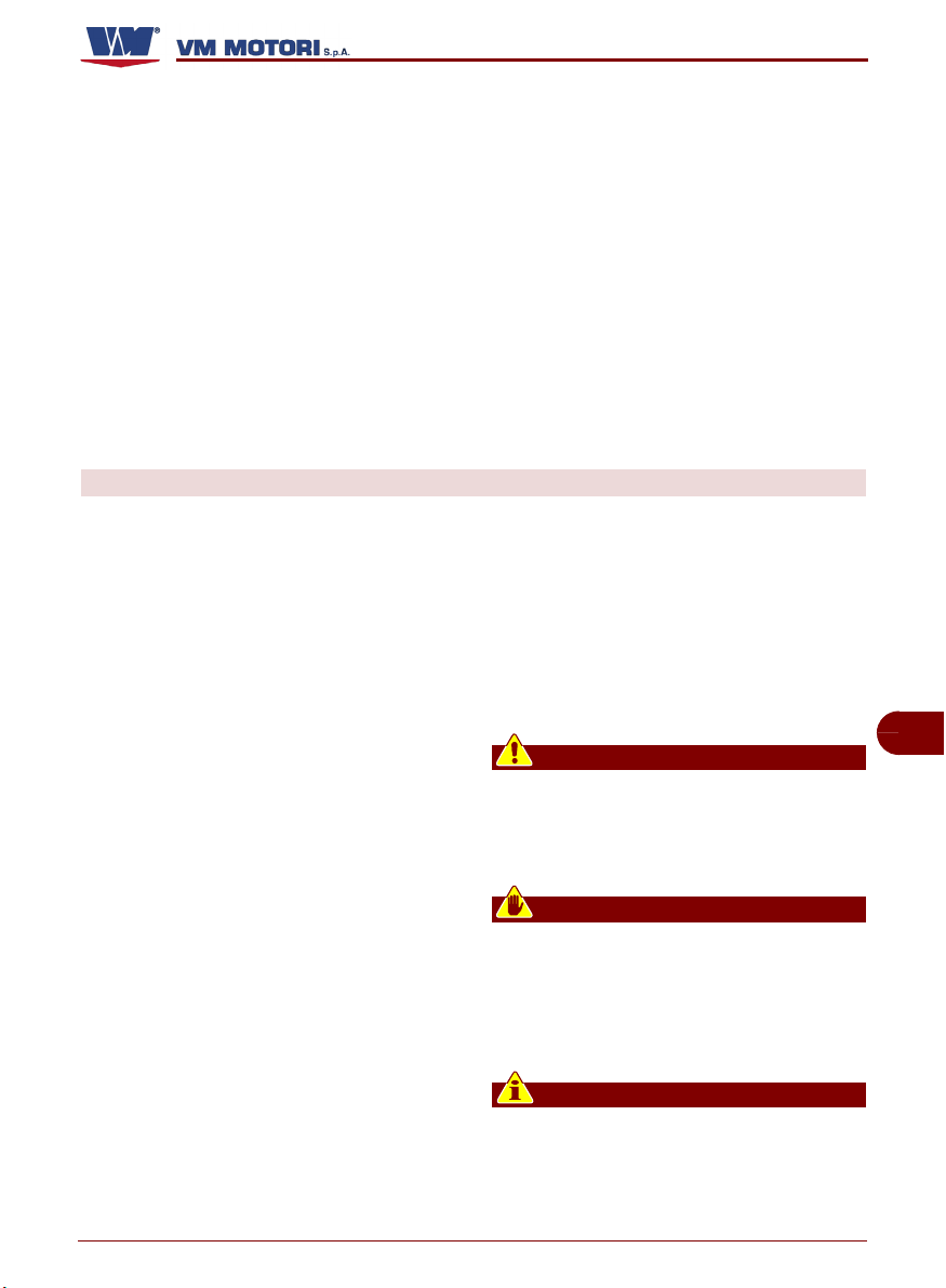
Pericolo - Attenzione
Indica situazioni di grave pericolo che,
se trascurate, possono mettere seriamente a rischio la salute e la sicurezza
delle persone.
Cautela - Avvertenza
Indica che è necessario adottare comportamenti adeguati per non mettere a rischio la salute e la sicurezza delle
persone e non provocare danni economici.
Importante
Indica informazioni tecniche di particolare importanza da non trascurare.
Italiano Informazioni generali
- 3 -
Page 8
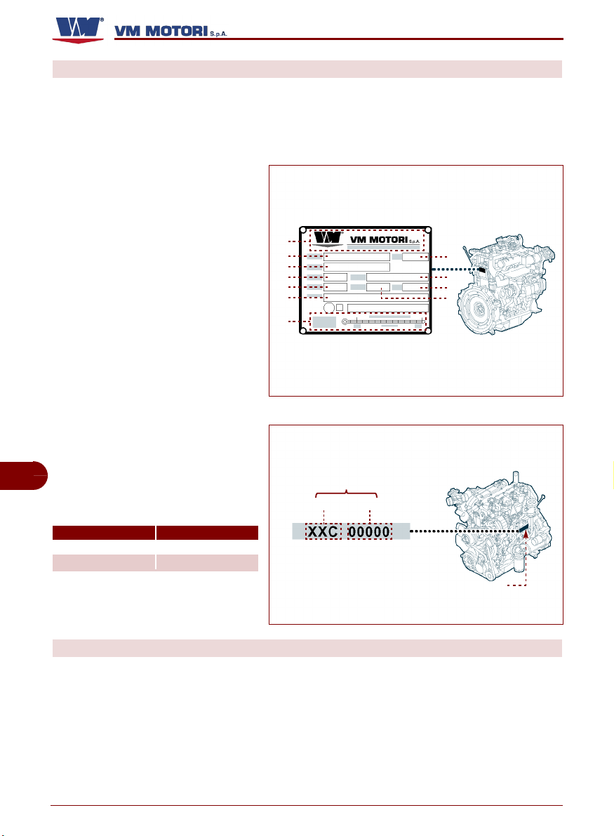
IDENTIFICAZIONE COSTRUTTORE E MOTORE
La targhetta di identificazione raffigurata è
applicata direttamente sul motore.
In essa sono riportati i riferimenti e tutte le
indicazioni indispensabili alla sicurezza di
esercizio.
A) Identificazione costruttore
B) Numero di matricola
C) Peso
D) Tipo
E) Famiglia
F) Modello
G) Versione
H) Potenza massima (kW)
L) Numero massimo di giri
M) Numero di omologazione
N) Caratteristiche olio di lubrificazio-
ne
P) Numero matricola motore (stam-
pigliato sul basamento)
q) Codice motore
IT
r) Numero progressivo
La tabella facilita l'identificazione del
modello tramite il codice motore.
Codice motore Modello motore
56 C R 754 EU4
79 C R 756 EU4
R750
A
B
D
E
G
M
N
P
qr
C
F
L
H
IDM-45300600100.tif
P
IDM-45300600200.tif
MODALITÀ DI RICHIESTA ASSISTENZA
Per ogni richiesta di assistenza tecnica ri-
C145300602.fm
guardante il motore, indicare i dati riportati
sulla targhetta di identificazione, il numero
di matricola, le ore approssimative di utilizzo
e il tipo di difetto riscontrato.
gata “Libretto indirizzi centri assistenza e
ricambi”).
Per ulteriori informazioni consultare il sito:
www.vmmotori.it, nella sezione “Contatti -
Richiedere info”.
Per qualsiasi esigenza rivolgersi al Servizio
Assistenza tecnica del costruttore o ad officine autorizzate (vedi Documentazione alle-
Italiano Informazioni generali
- 4 -
Page 9

CONDIZIONI DI GARANZIA
Le condizioni di garanzia sono riportate nella documentazione allegata (vedi “Scheda
di garanzia”)
DOCUMENTAZIONE ALLEGATA
Assieme a questo manuale, al cliente viene
rilasciata la documentazione indicata.
R750
– Libretto indirizzi centri assistenza e ri-
cambi
– Scheda di garanzia
C145300602.fm
Italiano Informazioni generali
- 5 -
IT
Page 10

INFORMAZIONI TECNICHE
DESCRIZIONE GENERALE MOTORE
I motori modello R754 EU4 - R756 EU4
sono stati progettati e costruiti per essere installati su veicoli stradali ad esempio spazzatrici, autocarri ecc. poichè omologati
secondo le direttive antiquinamento EURO 4.
I motori modello R754 IE3 - R756 IE3 sono
stati progettati per un uso non stradale, ma
per essere applicati su macchine di tipo
Componenti principali
A) Scambiatore di calore: raffredda l'olio
motore attraverso lo scambio termico
con il liquido di raffreddamento.
B) Turbo: costituito da una turbina che
sfrutta una parte dell'energia del gas di
scarico per effettuare la sovralimentazione del motore.
C) Valvola “EGR”: modula il ricircolo dei
gas di scarico prima che convoglino nel
collettore di aspirazione.
D) Valvola “waste-gate”: comanda l'atti-
vazione del turbo, in funzione della pres-
IT
sione dei gas di scarico.
E) Valvola termostatica: regola la tempe-
ratura dell'acqua in funzione della temperatura di esercizio del motore.
F) Filtro combustibile: trattiene le impuri-
tà.
G) Filtro olio: trattiene le impurità.
H) Coppa olio: contiene l'olio per la lubrifi-
cazione del motore.
L) Collettore di aspirazione: convoglia
l'aria comburente nella camera di combustione.
M) Pompa acqua: alimenta il circuito di raf-
freddamento.
C145300602.fm
N) Cinghia di trasmissione tipo Poly-V
(solo per motori modello R754EU4 R756EU4): aziona gli organi di servizio,
l'alternatore (Q) e la pompa acqua (M).
R750
agricolo o per il sollevamento di carichi.
I modelli di motore si differenziano fra loro
per potenza e prestazioni (vedi “Dati tecni-
ci”).
In dotazione vengono forniti alcuni accesso-
ri.
P) Tenditore automatico cinghia (solo
per motori modello R754EU4 R756EU4): mantiene la cinghia costan-
temente in tensione.
Q) Alternatore: produce e regola la tensio-
ne dell'impianto elettrico.
R) Motorino di avviamento: serve per av-
viare il motore.
S) Collettore di scarico: serve per l'espul-
sione dei gas di combustione.
T) Collettore acqua: serve per raccogliere
il liquido di raffreddamento proveniente
dalle testate.
U) Pompa iniezione ad alta pressione:
alimenta gli iniettori con combustibile in
pressione.
V) Iniettore: inietta combustibile in pressio-
ne nella camera di combustione.
W) Filtro antiparticolato: è installato nel
condotto del tubo di scarico del motore.
Serve per trattenere le particelle solide
(polveri sottili PM10) in modo da abbattere le emissioni prodotte dai motori diesel, responsabili dell'inquinamento
atmosferico.
Z) Rail: immagazzina combustibile in pres-
sione e lo distribuisce agli iniettori.
Italiano Informazioni tecniche
- 6 -
Page 11
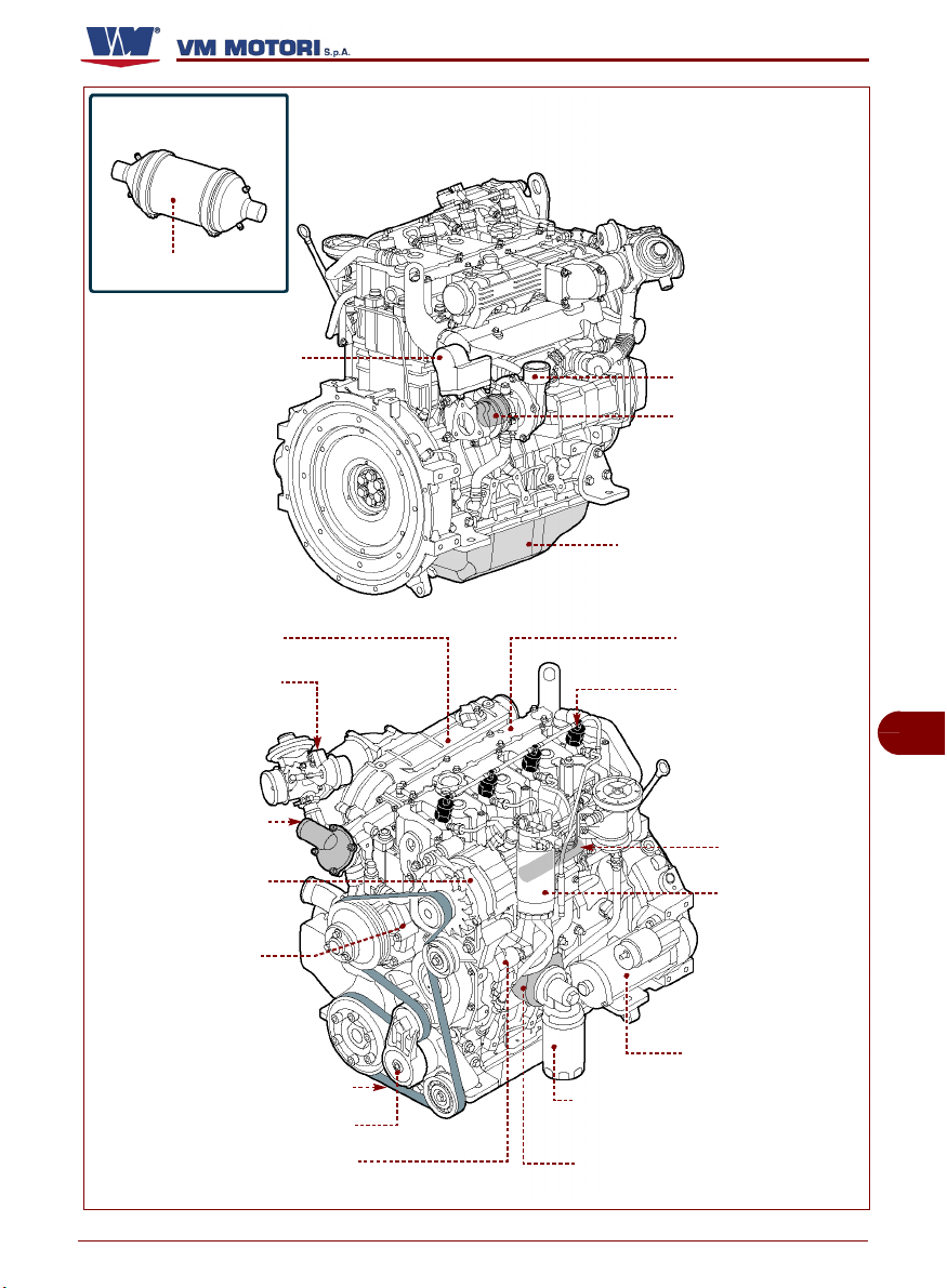
filtro antiparticolato (W)
collettore di scarico (S)
R750
turbo (B)
valvola "waste-gate" (D)
coppa olio (H)
collettore aspirazione (L)
valvola “EGR” (C)
valvola termostatica (E)
alternatore (Q)
pompa acqua (M)
C145300602.fm
cinghia trasmissione (N)
tenditore cinghia (P)
pompa iniezione alta pressione (U)
Italiano Informazioni tecniche
- 7 -
filtro olio (G)
scambiatore di calore (A)
collettore acqua (T)
iniettore (V)
rail (Z)
filtro
combustibile (F)
motorino di
avviamento (R)
IDM-45300600301.tif
IT
Page 12
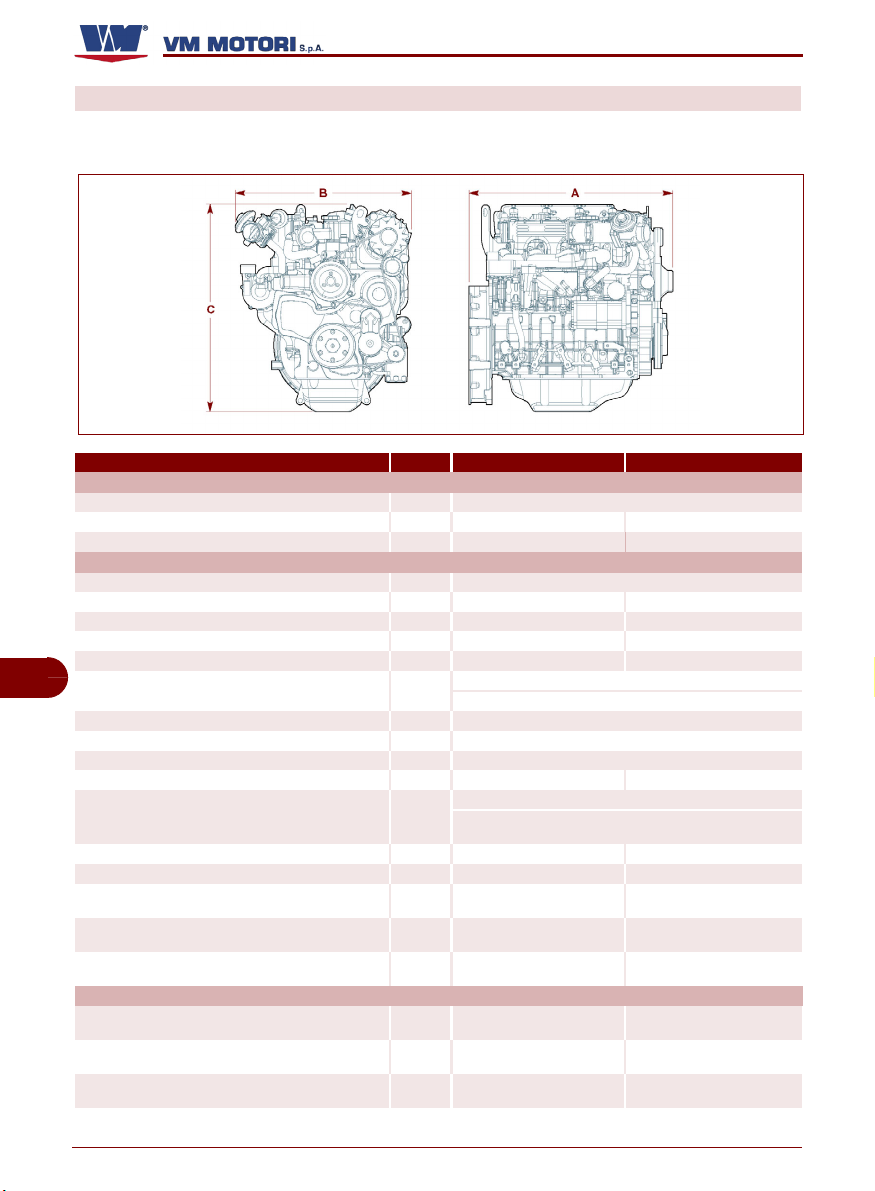
DATI TECNICI
Questi dati e specifiche tecniche si riferiscono esclusivamente a motori standard VM MOTORI S.P.A.
Modello R754 EU4 R756 EU4
A mm
B mm
C mm
Ciclo di funzionamento
Cilindrata totale litri
Quantità cilindri n.
Alesaggio x Corsa mm
Rapporto di compressione
IT
Aspirazione
Raffreddamento
Scambiatore di calore
Rotazione albero motore
Sequenza di scoppio
Distribuzione
Regime minimo a vuoto (motore standard) giri/min
Peso del motore a secco Kg
Massima inclinazione longitudinale
permanente (con volano in alto)
Massima inclinazione longitudinale
permanente (con volano in basso)
Massima inclinazione trasversale
C145300602.fm
permanente
Regime massimo di esercizio
Potenza massima
Coppia massima
DIMENSIONI
DATI GENERALI
Aste e bilanceri con punterie idrauliche e albero a camme
Gradi
Gradi
Gradi
POTENZA E COPPIA
giri/min
(rpm)
kW (CV)
giri/min
Nm (kgm)
giri/min
340 (34.65) a 1350 535 (54.53) a 1350
918 930
602 560
706 700
Diesel quattro tempi
2.970 4.455
4 6
94x107 94x107
17,8 ± 0.5:1 17,8 ± 0.5:1
Circuito sovralimentato e interrefrigerato
Filtro aria (a secco)
Circuito ad acqua
Senso antiorario (vista lato volano)
1-3-4-2 1-5-3-6-2-4
Comando a cascata di ingranaggi e albero a camme
800 +/-50 750 +/-50
260 335
30° 30°
35° 35°
30° 30°
3000 3000
74 (100) a 3000 121 (165) a 3000
Acqua/Olio
posizionato nel basamento
R750
IDM-45300600400.tif
Italiano Informazioni tecniche
- 8 -
Page 13
Modello R754 EU4 R756 EU4
CONSUMI ALLA POTENZA MASSIMA
Consumo specifico combustibile g/kWh
Consumo specifico olio g/CVh
274 254
0,3 0,3
CIRCUITO ALIMENTAZIONE
Tipo di iniezione
Tipo di combustibile
Alimentazione combustibile
Alimentazione iniettori
Il motore è stato progettato per essere alimentato con combustibili standard disponibili sul territorio europeo (secondo le specifi-
che DIN EN 590). In caso di alimentazione con combustibile
BIODIESEL (secondo le specifiche UNI EN 14214), esso può
essere miscelato, fino al 5%, con combustibile disponibile
sul territorio europeo (secondo la norma DIN EN 590).
Per motori modello R754EU4 - R756EU4, utilizzare combustibile
percentuale di zolfo non deve essere superiore a 10-50 ppm
È vietato l'uso di combustibili con specifiche diverse
Iniezione diretta Common Rail
con basso contenuto di zolfo. La
(parte per milione).
Importante
da quelle indicate.
Pompa ad ingranaggi
Pompa iniezione ad alta pressione
CIRCUITO LUBRIFICAZIONE
Tipo di lubrificazione
Alimentazione circuito
Cambio olio compreso filtro
(coppa standard)
Quantità olio al livello minimo
(coppa standard)
Quantità olio al livello massimo
(coppa standard)
Pressione olio a regime minimo
(a motore caldo)
Raffreddamento olio
litri (kg)
litri (kg)
litri (kg)
bar
Lubrificazione forzata
Pompa a rotori
7,8 (6.8) 9,4 (8.3)
6,6 (5.8) 7,5 (6.6)
7,4 (6.4) 8,4 (7.4)
1 - 1.5 1 - 1.5
Scambiatore olio/acqua
CIRCUITO RAFFREDDAMENTO
capacità totale circuito di raffreddamento
(senza radiatore e relative tubazioni)
Pressione taratura tappo vaso espansione bar
Liquido di raffreddamento
Allarme massima temperatura liquido di raffreddamento °C
litri
Acqua fredda demineralizzata 50% + Fluido antiossidante e anticongelante 50% (Glicol etilene inibito conforme a ASTM D 3306)
5 7.5
1 ± 0.1 1 ± 0.1
107 107
IMPIANTO ELETTRICO
Tensione nominale V
Alternatore (tensione nominale) V
Alternatore (corrente nominale) A
Potenza motorino avviamento kW
Capacità batteria consigliata Ah
Corrente di spunto batteria A
C145300602.fm
12 12
14 14
105 105
2,3 2,3
90 90
400 400
CIRCUITO ASPIRAZIONE
Massima depressione ammessa con filtro aria nuovo mbar
70 70
R750
IT
Italiano Informazioni tecniche
- 9 -
Page 14

INFORMAZIONI SULLA SICUREZZA
NORME PER LA SICUREZZA
– Il costruttore, in fase di progettazione e
costruzione, ha posto particolare attenzione agli aspetti che possono provocare rischi alla sicurezza e alla salute
delle persone che interagiscono con il
motore. Oltre al rispetto delle leggi vigenti in materia, egli ha adottato tutte le
“regole della buona tecnica di costruzione”. Scopo di queste informazioni è
quello di sensibilizzare gli utenti a porre
particolare attenzione per prevenire
qualsiasi rischio. La prudenza è comunque insostituibile. La sicurezza è
anche nelle mani di tutti gli operatori
che interagiscono con il motore.
– Leggere attentamente le istruzioni ri-
portate nel manuale in dotazione e
quelle applicate direttamente, in particolare rispettare quelle riguardanti la
sicurezza. Un po' di tempo dedicato
alla lettura risparmierà spiacevoli incidenti.
IT
– Prestare attenzione al significato dei
simboli delle targhette applicate; la loro
forma e colore sono significativi ai fini
della sicurezza. Mantenerle leggibili e
rispettare le informazioni indicate.
– Attuare solo gli usi previsti dal costrut-
tore e non manomettere alcun dispositivo per ottenere prestazioni diverse da
quelle previste.
– Il personale che effettua qualsiasi tipo
di intervento, in tutto l'arco di vita del
motore, deve possedere precise com-
C145300602.fm
petenze tecniche, particolari capacità
ed esperienze acquisite e riconosciute
nel settore specifico. La mancanza di
questi requisiti può causare danni alla
sicurezza e alla salute delle persone.
– Tutte le fasi di installazione devono es-
sere già considerate sin dalla realizza-
R750
zione del progetto iniziale. Il progettista
dovrà rispettare i punti di fissaggio del
motore e le indicazioni generali fornite
dal costruttore.
– Eseguire la movimentazione del moto-
re nel rispetto delle informazioni riportate direttamente sul motore,
sull'imballo e nelle istruzioni per l'uso
fornite dal costruttore.
– Il sollevamento ed il trasporto del moto-
re senza imballo vanno eseguiti con
mezzi di portata adeguata, ancorati nei
punti previsti.
– Il sollevamento ed il trasporto del moto-
re con imballo vanno eseguiti con mezzi di portata adeguata, come indicato
direttamente sull'imballo.
– Per trasferimenti successivi, creare le
condizioni necessarie per garantire la
stabilità ed evitare danneggiamenti alle
parti del motore.
– L'installatore, prima di iniziare la fase di
installazione, dovrà attuare un “piano di
sicurezza” e rispettare le indicazioni del
progettista. Per nessun motivo dovranno essere apportate modifiche ai componenti del motore.
– È necessario accertarsi che la zona di
installazione sia predisposta per tutti gli
allacciamenti di aspirazione, alimentazione e scarico.
– Il costruttore non si assume alcuna re-
sponsabilità per eventuali danni causati
dall'uso improprio del motore, dal mancato rispetto delle indicazioni contenute
nel presente manuale e da manomissioni o modifiche apportate senza autorizzazione.
Italiano Informazioni sulla sicurezza
- 10 -
Page 15

R750
– Anche dopo essersi documentati oppor-
tunamente, al primo uso, se necessario,
simulare alcune manovre di prova per individuare i comandi e le loro funzioni principali, in particolare quelle relative
all'accensione ed allo spegnimento.
– Non fare funzionare il motore in ambienti
chiusi e non sufficientemente arieggiati; i
fumi di scarico sono dannosi e possono
provocare conseguenze gravi alla salute
delle persone.
– Non continuare ad utilizzare il motore se
si riscontrano anomalie ed in particolare
se si verificano vibrazioni sospette.
– In caso di anomalia, arrestare immedia-
tamente il motore o ridurre al minimo le
prestazioni fino a raggiungere il più vicino
centro assistenza.
– Riavviare il motore solo dopo aver ripristi-
nato le normali condizioni d'esercizio.
– Ogni intervento, salvo quando espressa-
mente indicato, va eseguito a motore
spento, raffreddato e con chiave comando disinserita.
Chi è autorizzato ad eseguire tali interventi, dovrà tenere conto di tutti gli accorgimenti necessari per garantire la
sicurezza delle persone coinvolte, nel ri-
spetto dei requisiti rispondenti alle leggi
vigenti in materia di sicurezza sul lavoro.
– Mantenere il motore in condizioni di mas-
sima efficienza ed effettuare le operazioni di manutenzione programmata
previste dal costruttore. Una buona manutenzione consentirà di ottenere le migliori prestazioni, una più lunga durata di
esercizio e un mantenimento costante
dei requisiti di sicurezza.
– Sostituire i particolari troppo usurati con
ricambi originali. Usare gli oli e i grassi
consigliati dal costruttore. Tutto questo
potrà assicurare la funzionalità del motore ed il livello di sicurezza previsto.
– Non disperdere materiale inquinante
nell'ambiente. Effettuare lo smaltimento
nel rispetto delle leggi vigenti in materia.
– In fase di manutenzione utilizzare solo gli
indumenti e/o i dispositivi di protezione
individuali indicati nelle istruzioni per
l'uso fornite dal costruttore e quelli previsti dalle leggi vigenti in materia di sicurezza sul lavoro.
– Gli interventi di manutenzione vanno
eseguiti con l'uso di attrezzature ed utensili adeguati e in buone condizioni.
IT
NORME PER LA SICUREZZA SULL'IMPATTO AMBIENTALE
Ogni organizzazione ha il compito di applicare delle procedure per individuare, valutare e controllare l'influenza che le proprie
attività (prodotti, servizi, ecc.) hanno
sull'ambiente.
Le procedure da seguire per identificare im-
C145300602.fm
patti significativi sull'ambiente devono tener
conto dei seguenti fattori:
– Emissioni nell'atmosfera
– Scarichi dei liquidi
– Gestione dei rifiuti
– Uso delle materie prime e delle risorse
naturali
– Problematiche locali relative all'impatto
ambientale. Allo scopo di minimizzare
l'impatto ambientale, il costruttore fornisce, di seguito, alcune indicazioni che
dovranno essere tenute in considerazione da tutti coloro che, a qualunque titolo,
interagiscono con il motore nell'arco della
sua vita prevista.
– Contaminazione del suolo
Italiano Informazioni sulla sicurezza
- 11 -
Page 16

R750
– Tutti i componenti di imballo vanno smal-
titi secondo le leggi vigenti nel paese in
cui lo smaltimento viene effettuato.
– In fase di installazione del motore, fare in
modo che l'ambiente abbia un adeguato
ricambio d'aria per evitare la concentrazione di aria insalubre per gli operatori.
– In fase d'uso e manutenzione, evitare di
disperdere nell'ambiente prodotti inquinanti (oli, grassi, ecc.) e provvedere allo
smaltimento differenziato in funzione della composizione dei diversi materiali e
RISCHI RESIDUI
Il costruttore, in fase di progettazione e costruzione, ha posto particolare attenzione
agli aspetti che possono provocare rischi
alla sicurezza e alla salute delle persone
che interagiscono con il motore.
Nonostante ciò, permangono alcuni rischi
potenziali non evidenti.
IT
nel rispetto delle leggi vigenti in materia.
In caso di componenti elettrici ed elettronici provvedere allo smaltimento come rifiuti speciali.
– Mantenere efficienti i tubi di scarico per li-
mitare il livello di rumorosità del motore e
ridurre l'inquinamento atmosferico.
– In fase di dismissione del motore, sele-
zionare tutti componenti in funzione delle
loro caratteristiche chimiche e provvedere allo smaltimento differenziato.
Pericolo di lesioni arti superiori
Non introdurre le mani all'interno di organi in
movimento
Pericolo di scottatura
Fare attenzione alle superfici calde
C145300602.fm
Italiano Informazioni sulla sicurezza
- 12 -
Page 17
INFORMAZIONI SULLA MOVIMENTAZIONE E INSTALLAZIONE
RACCOMANDAZIONI PER LA MOVIMENTAZIONE E INSTALLAZIONE
Eseguire la movimentazione e l'installazione nel rispetto delle informazioni fornite dal
costruttore e riportate direttamente sull'imballo e nelle istruzioni per l'uso. Chi è auto-
rizzato ad eseguire queste operazioni
dovrà, se necessario, organizzare un “piano
di sicurezza” per salvaguardare l'incolumità
delle persone direttamente coinvolte.
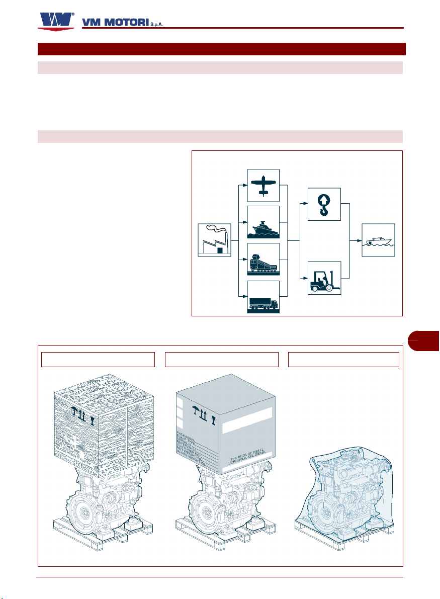
IMBALLO E TRASPORTO
L'imballo è realizzato, con contenimento degli ingombri, anche in funzione del tipo di trasporto adottato.
– via stradale
Mezzi di
trasporto
Mezzi di
sollevamento
– via ferroviaria
– via marittima
–via aerea
Il motore può essere trasportato con
diversi tipi di imballo in funzione della destinazione, delle modalità di trasporto e delle specifiche tecnicocommerciali predefinite.
R750
IDM-45300300700.tif
IT
Imballo con cassa in legno Imballo con scatola in cartone Imballo con cellofan
C145300602.fm
IDM-45300600500.tif
Italiano Informazioni sulla movimentazione e installazione
- 13 -
Page 18
Per garantire la perfetta conservazione dei componenti del motore, in
caso di trasporto marittimo, l'imballo
è di tipo “oltremare”.
Sull'imballo sono riportate tutte le informazioni necessarie ad effettuare
il carico e lo scarico. In fase di trasporto, al fine di evitare spostamenti
intempestivi, ancorare al mezzo di
trasporto in modo adeguato.
Per trasferimenti stradali del motore
senza coperture, utilizzare gli appositi punti di sollevamento per ancorarlo in modo stabile ed evitare
danneggiamenti ai componenti.
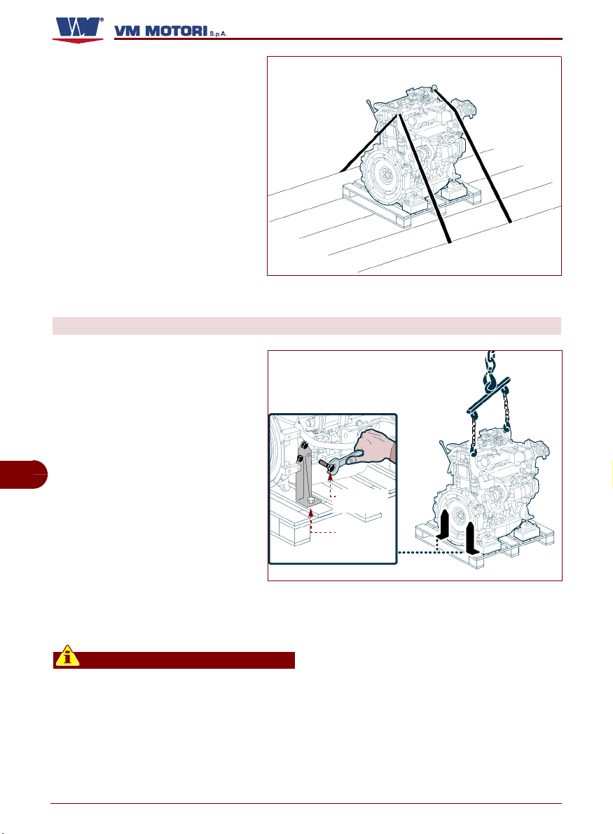
DISIMBALLO
Procedere nel modo indicato.
1- Rimuovere la copertura dell'imbal-
lo. All'interno dell'imballo è contenuta la busta con tutta la
documentazione tecnica di accompagnamento e gli accessori in
dotazione.
2- In fase di disimballo, controllare
IT
l'integrità e l'esatta quantità dei
componenti.
3- Posizionare il dispositivo di solle-
vamento come indicato in figura.
4- Svitare le viti (A) e smontare i sup-
porti laterali (B).
5- Trasferire il motore nella zona di
installazione.
Se necessario, conservare il materiale per successivi imballaggi.
R750
IDM-45300600600.tif
vite (A)
supporto (B)
IDM-45300600700.tif
Importante
In caso di danni o mancanza di alcune
C145300602.fm
parti, contattare il Servizio Assistenza
del costruttore per concordare le procedure da adottare. Il materiale di imballo
va opportunamente smaltito nel rispetto
delle leggi vigenti.
Italiano Informazioni sulla movimentazione e installazione
- 14 -
Page 19
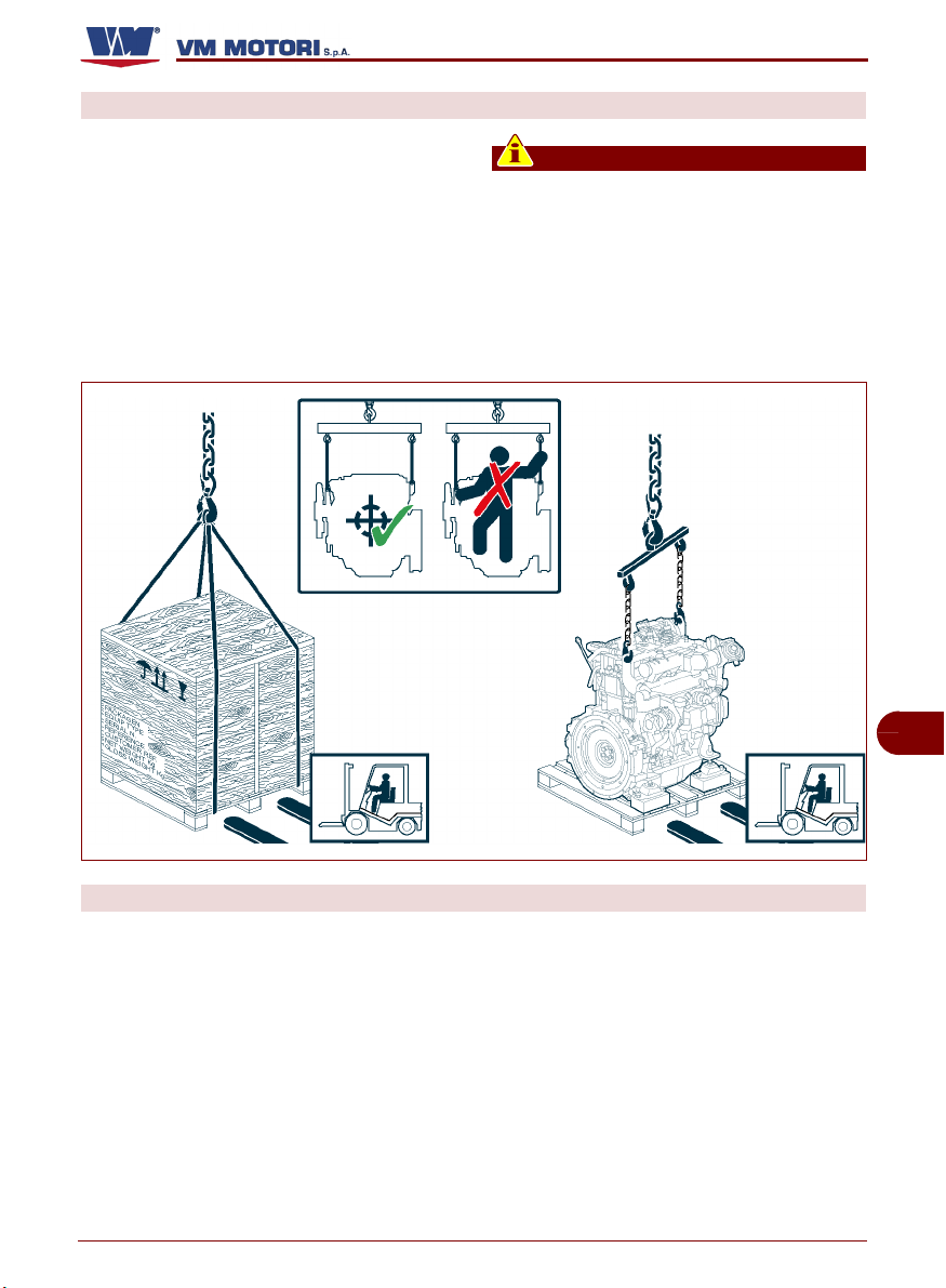
MOVIMENTAZIONE E SOLLEVAMENTO
Ancorare il motore con un dispositivo di sollevamento (bilancino) di portata adeguata.
Agganciare il dispositivo di sollevamento ai
punti di attacco indicati in figura.
Prima di effettuare il sollevamento, controllare la posizione del baricentro del carico.
R750
Importante
Le staffe dei punti di attacco sono dimensionate per sollevare solo il motore
e non sono omologate per sollevare pesi
aggiuntivi. Non sollevare il motore con
modalità diverse rispetto a quelle indicate; in caso contrario decadrà la garanzia
assicurativa per i danni riportati.
IDM-45300600800.tif
STOCCAGGIO MOTORE
In caso di inattività prolungata, verificare le
condizioni dell'ambiente di stoccaggio, il
tipo di imballo e controllare che tali condizioni assicurino un corretto mantenimento del
motore.
C145300602.fm
Evitare ambienti umidi ed esposti ad intemperie.
Il costruttore consegna il motore già sottoposto ad un trattamento di protezione valido
per 6 mesi a partire dalla data di fornitura.
Trascorsi i primi 6 mesi, se il motore non viene utilizzato, è necessario eseguire una
specifica manutenzione per estendere il periodo di stoccaggio per ulteriori 6 mesi.
Per le informazioni relative all'estensione
del periodo di stoccaggio, consultare le condizioni generali di garanzia.
Italiano Informazioni sulla movimentazione e installazione
- 15 -
IT
Page 20

PROGETTAZIONE DELL'INSTALLAZIONE
R750
Al fine di assicurare le massime prestazioni
e garantire la sicurezza per le persone, per
il prodotto e l'ambiente, prima di procedere
all'installazione, è necessario eseguire un
progetto completo.
In fase di progettazione, è necessario considerare i dati tecnici del motore (vedi “Dati
tecnici”) e analizzare tutti i rischi che possono verificarsi nell'arco della sua vita prevista: dall'installazione allo smaltimento.
IT
In fase di progettazione e installazione, è opportuno consultare anche l'apposito manuale
di servizio realizzato da VM MOTORI S.P.A.
Per ulteriori informazioni consultare il sito:
www.vmmotori.it, nella sezione “Contatti Richiedere info”.
C145300602.fm
Italiano Informazioni sulla movimentazione e installazione
- 16 -
Page 21
INFORMAZIONI SULL'USO
RACCOMANDAZIONI PER L'USO E FUNZIONAMENTO
Il motore è stato progettato e costruito per
soddisfare tutte le condizioni operative indicate dal costruttore. Manomettere qualsiasi
da quelle previste può comportare rischi per
la sicurezza e la salute delle persone e danni economici.
dispositivo per ottenere prestazioni diverse
CONSIGLI PER L'USO
Il motore viene consegnato dalla
fabbrica in ordine di marcia. Durante
l'uso è comunque necessario attenersi alle seguenti indicazioni:
1- Durante il rodaggio (prime 50 ore
di esercizio) e in tutto l'arco di
vita del motore, effettuare la manutenzione secondo gli intervalli
stabiliti dal costruttore (vedi “Manutenzione del motore”).
2- Se il motore non viene usato re-
golarmente, ogni mese di inattività è necessario metterlo in moto
e farlo girare a regime minimo
fino a raggiungere la temperatura di esercizio (70÷80°C).
3- Evitare di utilizzare il motore al massimo
delle sue prestazioni per lunghi periodi
durante il rodaggio.
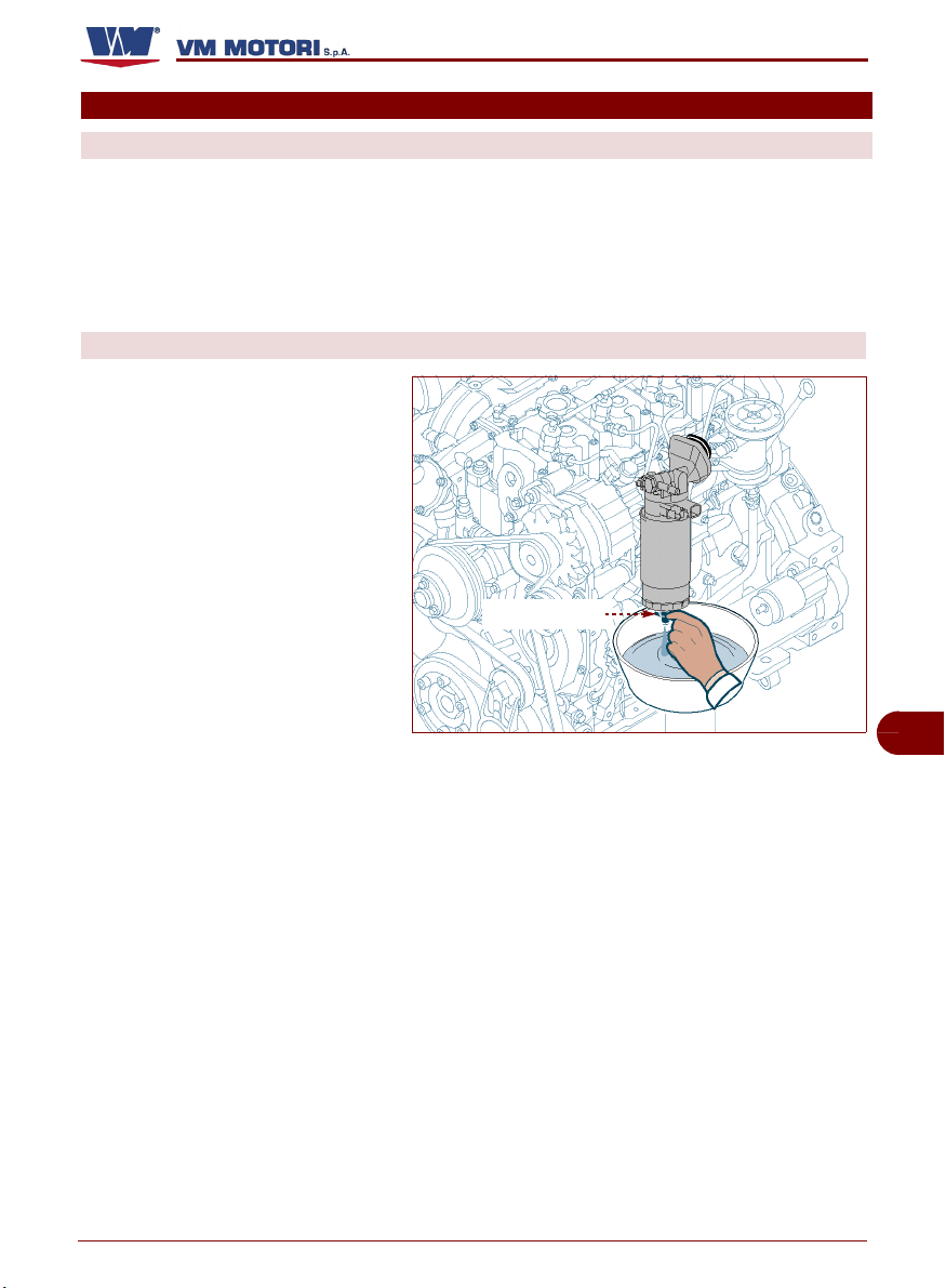
4- Al primo avviamento far girare il motore
7- In caso di accensione della spia di allar-
me “presenza acqua nel combustibile”,
procedere come segue:
– Spegnere il motore e disinserire la
a vuoto e a regime minimo per alcuni minuti e controllare che il valore della pres-
– Lasciare raffreddare adeguatamente il
sione dell'olio corrisponda a quello
riportato in tabella (vedi “Dati tecnici” -
– Predisporre un recipiente di capienza
“Circuito lubrificazione”).
5- Preriscaldare adeguatamente il motore
– Svitare il tappo (A) posto alla base inin caso d'uso a basse temperature.
In caso d'uso a basse temperature (infe-
C145300602.fm
riori a -10°C), rifornire con carburante di
tipo invernale.
6- Utilizzare oli e lubrificanti con caratteri-
stiche adeguate (gradazione, specifiche
e temperatura d'esercizio) (vedi “Lubrificanti consigliati”)
R750
tappo (A)
IDM-45300601800.tif
chiave di accensione.
motore, per evitare rischi di scottature.
adeguata.
feriore del filtro combustibile e lasciare
defluire il combustibile fino a quando
non è privo di acqua.
IT
Italiano Informazioni sull'uso
- 17 -
Page 22
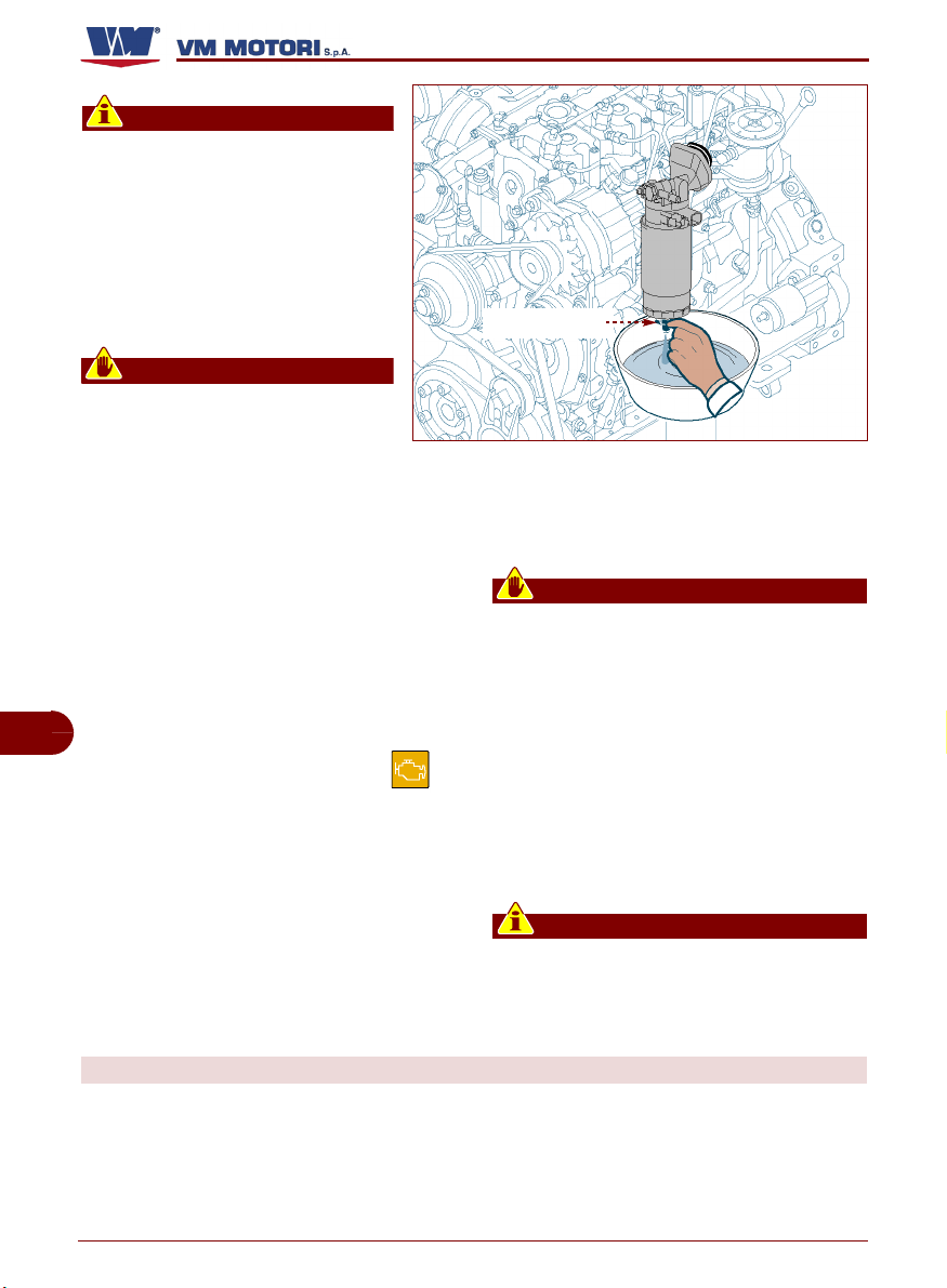
Importante
Fare attenzione che non fuori
esca tutto il combustibile contenuto nel filtro. In tale caso, procedere alla sua rimozione (vedi
“Cambio filtro combustibile”), effettuarne manualmente il riempimento e ripetere l'operazione di
spurgo.
Cautela - Avvertenza
Non disperdere materiale inquinante nell'ambiente. Effettuare lo
smaltimento nel rispetto delle leggi vigenti in materia.
– Riavvitare il tappo (A).
8- L'attivazione di una segnalazione di al-
larme (visiva e/o acustica) proveniente
dal quadro comandi indica la presenza
di un'anomalia.
In presenza di anomalie, il sistema di
gestione elettronica attiva il funzionamento del motore in condizioni di
emergenza con la limitazione auto-
IT
matica delle sue prestazioni.
In tali condizioni la spia (MIL) si
accende e le cause da ricercare possono essere il malfunzionamento del
motore o del filtro antiparticolato.
R750
tappo (A)
IDM-45300601800.tif
ti da adottare e rimediare alle cause
che hanno generato le condizioni di
emergenza.
Cautela - Avvertenza
Non continuare ad utilizzare il motore
con la spia MIL accesa. Se l'accensione
della spia è causata dal malfunzionamento del filtro antiparticolato, può sussistere il rischio di incendio.
Non tentare di disconnettere il sensore
di funzionamento della spia MIL per eliminare il segnale. VM motori non si assume alcuna responsabilità in caso di
danni economici o rischi alla sicurezza
delle persone.
Per risolvere l'anomalia riscontrata, procedere nel modo indicato.
– Spegnere il motore.
– Consultare il capitolo “Informazioni sui
guasti” per conoscere i comportamen-
C145300602.fm
Importante
Per maggiori informazioni, consultare la
documentazione fornita dal costruttore
del veicolo/dispositivo in cui il motore è
installato.
FUNZIONAMENTO DEL MOTORE IN CONDIZIONI PARTICOLARI
Le prestazioni del motore sono influenzate
dalla temperatura del combustibile, dalla
temperatura e umidità relativa dell'aria in
aspirazione e dall’altitudine.
In caso di uso del motore ad alta quota, a
temperature elevate dell'aria e del combustibile, la potenza erogata si riduce.
Per maggiori informazioni contattare un
centro assistenza VM MOTORI S.P.A.
Italiano Informazioni sull'uso
- 18 -
Page 23
ACCENSIONE E SPEGNIMENTO MOTORE
Il motore non è dotato di quadro comandi.
Per le informazioni riguardanti comandi e dispositivi di controllo consultare la documen-
RIFORNIMENTO COMBUSTIBILE
R750
tazione fornita dal costruttore del veicolo/
dispositivo in cui il motore è installato.
Durante il rifornimento, assicurarsi che il
combustibile non contenga residui, in caso
contrario usare appositi filtri.
Evitare di utilizzare combustibile mescolato
ad acqua o ad altre sostanze per non provocare danni al motore.
Il motore è stato progettato per essere alimentato con combustibili standard disponibili sul territorio europeo (secondo le
specifiche DIN EN 590). In caso di alimentazione con combustibile BIODIESEL (secondo le specifiche UNI EN 14214), esso può
essere miscelato, fino al 5%, con combustibile disponibile sul territorio europeo (secondo la norma DIN EN 590).
Cautela - Avvertenza
È vietato l'uso di combustibili con specifiche diverse da quelle indicate.
Per motori modello R754EU4 - R756EU4,
utilizzare combustibile con basso contenuto
di zolfo. La percentuale di zolfo non deve
essere superiore a 10-50 ppm (parte per milione).
Cautela - Avvertenza
Se la percentuale di zolfo contenuto nel
combustibile è superiore al valore indicato, si compromette la funzionalità del
filtro antiparticolato.
Pericolo - Attenzione
Tutti i combustibili sono infiammabili. Le
perdite e la caduta di combustibile su superfici calde e su componenti elettrici
possono causare incendi. Non fumare
quando si fa rifornimento o quando ci si
trova in tale area.
IT
C145300602.fm
Italiano Informazioni sull'uso
- 19 -
Page 24

INFORMAZIONI SULLA MANUTENZIONE
RACCOMANDAZIONI PER LA MANUTENZIONE
Mantenere il motore in condizioni di massima efficienza, con le operazioni di manutenzione programmata previste dal costruttore.
Se ben effettuate, si potranno ottenere migliori prestazioni, una più lunga durata di
esercizio e un mantenimento costante dei
requisiti di sicurezza.
Cautela - Avvertenza
Ogni intervento, salvo quando espressamente indicato, va eseguito a motore
spento e freddo. Chi è autorizzato ad
eseguire tali interventi, dovrà tenere conto di tutti gli accorgimenti necessari per
MANUTENZIONE DEL MOTORE
Le operazioni di manutenzione sono suddivise in:
– Manutenzione in fase di rodaggio (prime 50
IT
ore)
– Manutenzione ordinaria (dopo il rodaggio)
La frequenza indicata nella tabella “manutenzione ordinaria” si riferisce ad un'attività
giornaliera costante del motore.
Alcuni lubrificanti o componenti del motore,
anche in caso di inattività, perdono le loro
caratteristiche nel tempo, quindi, nella valu-
R750
garantire la sicurezza delle persone coinvolte, nel rispetto dei requisiti rispondenti alle leggi vigenti in materia di
sicurezza sul lavoro.
Importante
Per ogni intervento di manutenzione
compilare l'apposita “Scheda di registrazione degli interventi di manutenzione
periodica” in modo da conservare la
tracciabilità delle operazioni effettuate e
poter quindi stabilire le modalità più adeguate per i futuri interventi.
tazione degli intervalli di manutenzione, è
necessario considerare anche la loro sostituzione per l'invecchiamento e non per le
ore di funzionamento.
Di seguito è riportato indicativamente il tempo massimo di mantenimento delle caratteristiche chimico-fisiche di alcuni componenti
o lubrificanti.
– 1 anno: Olio lubrificante
– 1 anno: Cartuccia filtro combustibile
– 2 anni: Liquido di raffreddamento
C145300602.fm
Italiano Informazioni sulla manutenzione
- 20 -
Page 25

Tabella manutenzione in fase di rodaggio (prime 50 ore)
Importante
Per ogni intervento di manutenzione
compilare l'apposita “Scheda di registrazione degli interventi di manutenzione
tracciabilità delle operazioni effettuate e
poter quindi stabilire le modalità più adeguate per i futuri interventi.
periodica” in modo da conservare la
(1)
Frequenza
Ogni 10 ore
(ogni giorno)
dopo le prime
50 ore (a fine
rodaggio)
Componente Tipo di intervento Modalità di intervento Riferimento
Olio motore
Liquido di raffreddamento
Filtro aria Controllo pulizia
Radiatore liquido di
raffreddamento
Filtro olio Sostituzione
(2)
(4)
Controllo livello
Controllo livello
Controllo pulizia
Rabboccare, se necessario
Rabboccare, se necessario
Pulire con aria compressa a bassa pressione.
Sostituire, se necessario
Pulire con spazzola a
setole morbide
R750
Vedi “Controllo livello
olio motore”
Vedi “Controllo livello
liquido raffreddamento
motore”
Vedi “Cambio cartuccia
filtro olio
”
Tabella manutenzione ordinaria (dopo il rodaggio)
Importante
Per ogni intervento di manutenzione
compilare l'apposita “Scheda di registrazione degli interventi di manutenzione
tracciabilità delle operazioni effettuate e
poter quindi stabilire le modalità più adeguate per i futuri interventi.
periodica” in modo da conservare la
(1)
Frequenza
Ogni 10 ore
C145300602.fm
Ogni 300 ore
Italiano Informazioni sulla manutenzione
Componente Tipo di intervento Modalità di intervento Riferimento
Olio motore
Liquido di raffreddamento
Filtro aria Controllo pulizia
Radiatore liquido
di raffreddamento
Olio motore
Filtro olio
(2)
(4)
(2)
Controllo livello
Controllo livello
Controllo pulizia
Sostituire
Sostituire la cartuccia
Rabboccare, se necessario
Rabboccare, se necessario
Pulire con aria compressa a bassa pressione.
Sostituire, se necessario
Pulire con spazzola a
setole morbide
Vedi “Controllo livello
olio motore”
Vedi “Controllo livello
liquido raffreddamento motore”
Vedi “Cambio olio
”
motore
Vedi “Cambio cartuc-
cia filtro olio
- 21 -
”
IT
Page 26
R750
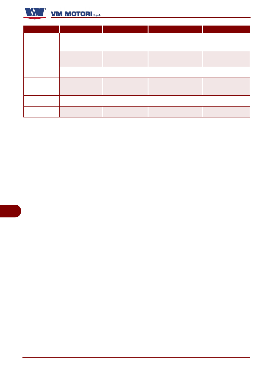
(1)
Frequenza
Ogni 300 ore
(ogni
30.000 km)
Ogni 900 ore
Ogni 1200 ore
Ogni 1500 ore
(ogni
50.000 km)
Ogni 4000 ore Motore
Ogni 8000 ore Motore
(1) In caso di mancanza di contaore, la frequenza degli interventi va calcolata in funzione del giorno solare: un giorno
solare corrisponde a 12 ore di funzionamento.
(2) In condizioni di lavoro gravose, come ambienti polverosi e funzionamento a carichi estremi, effettuare la sostituzione
dell'olio motore ogni 150 ore di funzionamento. Se il motore non è stato in esercizio per il tempo indicato, è necessario
effettuare ugualmente la sostituzione dell'olio almeno una volta all'anno.
(3) Se il motore non è stato in esercizio per il tempo indicato, è necessario effettuare ugualmente la sostituzione del
filtro almeno ogni 12 mesi.
(4) Se il motore non è stato in esercizio per il tempo indicato, è necessario effettuare ugualmente la sostituzione del
liquido almeno ogni 24 mesi.
(5) Se il motore non è stato in esercizio per il tempo indicato, è necessario effettuare ugualmente la sostituzione della
cinghia almeno ogni 24 mesi.
Componente Tipo di intervento Modalità di intervento Riferimento
Filtro combusti-
(3)
bile
Cinghia di trasmissione (tipo
(5)
Poly-V)
Liquido di raffred-
(4)
damento
Filtro antiparticolato
Sostituire
Sostituire
Sostituire
Pulire
Effettuare la revisione parziale
Effettuare la revisione generale
Rivolgersi ad una officina autorizzata
Rivolgersi ad una officina autorizzata
Vedi “Cambio filtro
combustibile”
Vedi “Sostituzione
cinghia (tipo Poly-V)”
Vedi “Cambio liquido
di raffreddamento
Vedi "Pulizia filtro
antiparticolato"
”
IT
C145300602.fm
Italiano Informazioni sulla manutenzione
- 22 -
Page 27
Scheda di registrazione degli interventi di manutenzione periodica
Importante
Per ogni intervento di manutenzione
compilare la scheda in modo da conser-
tuate e poter quindi stabilire le modalità
più adeguate per i futuri interventi.
vare la tracciabilità delle operazioni effet-
R750
Data
Ore
(1)
Tipo di manutenzione effettuata Timbro e firma officina
..........................................................................
..........................................................................
..........................................................................
..........................................................................
..........................................................................
..........................................................................
_____ _____ _____________________________________ ________________
..........................................................................
..........................................................................
..........................................................................
..........................................................................
..........................................................................
..........................................................................
_____ _____ _____________________________________ ________________
..........................................................................
..........................................................................
..........................................................................
C145300602.fm
..........................................................................
..........................................................................
..........................................................................
_____ _____ _____________________________________ ________________
IT
(1) Indicare le ore totali di funzionamento.
Italiano Informazioni sulla manutenzione
- 23 -
Page 28

R750
Data
Ore
(1)
Tipo di manutenzione effettuata Timbro e firma officina
..........................................................................
..........................................................................
..........................................................................
..........................................................................
..........................................................................
..........................................................................
_____ _____ _____________________________________ ________________
..........................................................................
..........................................................................
..........................................................................
..........................................................................
..........................................................................
..........................................................................
_____ _____ _____________________________________ ________________
..........................................................................
..........................................................................
..........................................................................
..........................................................................
..........................................................................
..........................................................................
IT
_____ _____ _____________________________________ ________________
..........................................................................
..........................................................................
..........................................................................
..........................................................................
..........................................................................
..........................................................................
_____ _____ _____________________________________ ________________
..........................................................................
..........................................................................
C145300602.fm
..........................................................................
..........................................................................
..........................................................................
..........................................................................
_____ _____ _____________________________________ ________________
(1) Indicare le ore totali di funzionamento.
Italiano Informazioni sulla manutenzione
- 24 -
Page 29
R750
Data
Ore
(1)
Tipo di manutenzione effettuata Timbro e firma officina
..........................................................................
..........................................................................
..........................................................................
..........................................................................
..........................................................................
..........................................................................
_____ _____ _____________________________________ ________________
..........................................................................
..........................................................................
..........................................................................
..........................................................................
..........................................................................
..........................................................................
_____ _____ _____________________________________ ________________
..........................................................................
..........................................................................
..........................................................................
..........................................................................
..........................................................................
..........................................................................
_____ _____ _____________________________________ ________________
..........................................................................
..........................................................................
C145300602.fm
..........................................................................
..........................................................................
..........................................................................
..........................................................................
_____ _____ _____________________________________ ________________
IT
(1) Indicare le ore totali di funzionamento.
Italiano Informazioni sulla manutenzione
- 25 -
Page 30
R750
Data
Ore
(1)
Tipo di manutenzione effettuata Timbro e firma officina
..........................................................................
..........................................................................
..........................................................................
..........................................................................
..........................................................................
..........................................................................
_____ _____ _____________________________________ ________________
..........................................................................
..........................................................................
..........................................................................
..........................................................................
..........................................................................
..........................................................................
_____ _____ _____________________________________ ________________
..........................................................................
..........................................................................
..........................................................................
..........................................................................
..........................................................................
..........................................................................
IT
_____ _____ _____________________________________ ________________
..........................................................................
..........................................................................
..........................................................................
..........................................................................
..........................................................................
..........................................................................
_____ _____ _____________________________________ ________________
..........................................................................
..........................................................................
C145300602.fm
..........................................................................
..........................................................................
..........................................................................
..........................................................................
_____ _____ _____________________________________ ________________
(1) Indicare le ore totali di funzionamento.
Italiano Informazioni sulla manutenzione
- 26 -
Page 31

MANUTENZIONE IN CASO DI INATTIVITÀ DEL MOTORE
Se il veicolo/apparecchiatura su cui è installato il motore rimane inattivo, è necessario
effettuare alcuni interventi di manutenzione
per mantenere il motore in condizioni di
massima efficienza.
In caso di brevi periodi di inattività, effettuare i seguenti interventi:
1- Controllare l'efficienza dei contatti elet-
trici e, se necessario, proteggerli con
uno spray antiossidante.
2- Controllare la carica della batteria e il li-
vello del liquido.
3- Eseguire, se necessario, gli interventi di
manutenzione programmati (vedi “Manutenzione del motore”)
È consigliabile comunque mettere in moto il
motore e portarlo alla temperatura di esercizio (70÷80°C) almeno una volta al mese.
È obbligatorio mettere in moto il motore una
volta al mese, qualora sia installato per impieghi di emergenza.
In caso di lunghi periodi di inattività, per evitare continui interventi di controllo e manutenzione, effettuare il trattamento protettivo
del motore in modo da garantirne l'efficienza
per 6 mesi. Se l'inattività si prolunga ulteriormente, verificare la necessità di ripetere il
trattamento protettivo per altri 6 mesi (vedi
“Trattamento protettivo motore”).
TRATTAMENTO PROTETTIVO MOTORE
Procedere nel modo indicato.
1- Controllare che l'olio motore e il liquido
di raffreddamento siano a livello.
2- Riempire il serbatoio di servizio con una
miscela composta da 10% di olio protettivo (Castrol Safecoat DW30X, Rustilo
181, Rustilo DWX31) e 90% di combustibile.
ve di accensione.
7- Lasciare raffreddare adeguatamente il
motore, per evitare rischi di scottature.
8- Proteggere i contatti elettrici con uno
spray antiossidante.
9- Proteggere il motore con cere e/o spray
antiossidante di resine sintetiche.
10-Scollegare i morsetti della batteria.
11-Riempire completamente il serbatoio di
Importante
Per questa operazione è possibile utilizzare un serbatoio supplementare, con attacchi per il collegamento al circuito di
alimentazione del motore.
3- Scollegare dal motore tutti gli organi
meccanici e le applicazioni ausiliarie che
potrebbero danneggiarsi con il funziona-
C145300602.fm
mento a vuoto.
combustibile.
12-Allentare la cinghia di trasmissione per
garantire una più lunga durata (vedi
“Modalità per allentare o tendere la cin-
ghia (tipo Poly-V)”)
13-Assicurarsi che il motore rimanga al ri-
paro dagli agenti atmosferici.
4- Accendere il motore e mantenerlo al re-
gime minimo per 5 minuti.
5- Portare il motore a 1500÷1800 giri/min
per 15 minuti fino al raggiungimento della temperatura di esercizio (70÷80°C).
6- Spegnere il motore e disinserire la chia-
R750
IT
Italiano Informazioni sulla manutenzione
- 27 -
Page 32

MANUTENZIONE PER RIMESSA IN ATTIVITÀ DEL MOTORE
Dopo un periodo di inattività, prima di rimettere in moto il motore, è necessario effettuare alcuni interventi di manutenzione per
garantire condizioni di massima efficienza.
– Controllare la carica della batteria e il li-
vello del liquido.
– Controllare l'integrità e l'efficienza dei
contatti elettrici.
– Eseguire la diagnosi della funzionalità
del motore
– Controllare il livello dell'olio e, se ne-
cessario, rabboccare o sostituirlo in
base alla frequenza stabilita (vedi “Tabella manutenzione ordinaria - dopo il
rodaggio”)
– Sostituire il filtro olio in base alla fre-
quenza stabilita (vedi “Tabella manutenzione ordinaria - dopo il rodaggio”)
– Controllare il livello del liquido di raf-
freddamento e, se necessario, rabboccare o sostituirlo in base alla frequenza
stabilita (vedi “Tabella manutenzione
ordinaria - dopo il rodaggio”)
– Sostituire il filtro combustibile in base
alla frequenza stabilita (vedi “Tabella
IT
– Sostituire il filtro aria in base alla fre-
quenza stabilita (vedi “Tabella manutenzione ordinaria - dopo il rodaggio”)
– Rimettere in tensione la cinghia di tra-
smissione (vedi “Modalità per allentare
o tendere la cinghia (tipo Poly-V)”)
– Controllare il serraggio dei raccordi
idraulici (vedi “Controllo serraggio viti e
tenuta raccordi”)
– Controllare l'integrità dei manicotti in
gomma e delle relative fascette di fissaggio.
– Utilizzare un panno imbevuto di prodot-
to sgrassante per rimuovere il trattamento protettivo esterno.
– Accendere il motore e mantenerlo al re-
gime minimo per qualche minuto (vedi
“Accensione e spegnimento motore”).
– Se non si riscontrano anomalie di fun-
zionamento, portare il motore alla temperatura di esercizio (70÷80°C).
– Spegnere il motore e controllare nuova-
mente che l'olio motore e il liquido di
raffreddamento siano a livello.
manutenzione ordinaria - dopo il rodaggio”).
R750
VERIFICHE E CONTROLLI
L'elenco riporta alcune delle attività di manutenzione, verifica e controllo da effettuare
sul motore durante il normale esercizio.
– Cambio cartuccia filtro olio
– Cambio filtro combustibile
– Pulizia filtro antiparticolato
– Spurgo circuito alimentazione
– Controllo serraggio viti e tenuta raccordi
– Controllo livello olio motore
C145300602.fm
– Controllo livello liquido raffreddamento
motore
– Modalità per allentare o tendere la cin-
ghia
– Cambio olio motore
– Cambio liquido di raffreddamento
Italiano Informazioni sulla manutenzione
- 28 -
Importante
Per ogni intervento di manutenzione
compilare l'apposita “Scheda di registrazione degli interventi di manutenzione
periodica” in modo da conservare la
tracciabilità delle operazioni effettuate e
poter quindi stabilire le modalità più adeguate per i futuri interventi.
Page 33

SPURGO CIRCUITO ALIMENTAZIONE
Importante
Questa operazione deve essere
eseguita dopo ogni cambio della
cartuccia combustibile
Procedere nel modo indicato.
1- Spegnere il motore e disinserire
la chiave di accensione.
2- Lasciare raffreddare adeguata-
mente il motore, per evitare rischi
di scottature.
3- Predisporre un recipiente di ca-
pienza adeguata.
4 -Allentare la vite (E).
5 -Azionare manualmente la pom-
pa (G) per eliminare l'aria dal circuito.
6 -Verificare che dalla vite di spurgo (E)
fuori esca un flusso di gasolio pulito privo di aria.
Importante
Fare attenzione che non fuori esca tutto
il combustibile contenuto nel filtro. In
tale caso, procedere alla sua rimozione
R750
pompa (G)
vite spurgo (E)
IDM-45300600900.tif
(vedi “Cambio filtro combustibile”), effettuarne manualmente il riempimento e
ripetere l'operazione di spurgo.
7- Serrare la vite (E).
8- Asciugare i residui di combustibile prima
di accendere il motore.
IT
CONTROLLO SERRAGGIO VITI E TENUTA RACCORDI
Procedere nel modo indicato.
1- Accendere il motore e mantenerlo al re-
gime minimo per qualche minuto.
2- Portare il motore a regime fino a rag-
giungere la temperatura di esercizio
(70÷80°C).
4- Controllare il serraggio delle viti di fis-
saggio degli organi principali.
5- Verificare la tenuta dei raccordi sul cir-
cuito di alimentazione.
6- Controllare il serraggio delle fascette.
7- Verificare eventuali perdite di fluidi.
3- Spegnere il motore e lasciarlo raffredda-
re
C145300602.fm
Italiano Informazioni sulla manutenzione
- 29 -
Page 34

CONTROLLO LIVELLO OLIO MOTORE
Procedere nel modo indicato.
1- Accendere il motore e portarlo
alla temperatura di esercizio
(70÷80 °C).
2- Spegnere il motore e disinserire
la chiave di accensione.
3- Posizionare il motore perfetta-
mente in piano.
4- Attendere alcuni minuti per fare
defluire tutto l'olio nella coppa.
5- Estrarre l'asta (L) e controllare il
livello dell'olio.
6- Rabboccare, se necessario, dal
tappo (M). Per la quantità di olio,
vedi “Dati tecnici”.
Importante
Il livello dell'olio deve essere compreso fra i riferimenti di minimo e
massimo. Non mescolare oli di
marche o caratteristiche diverse
(vedi “Lubrificanti consigliati”)
asta (L)
R750
tappo carico (M)
IDM-45300601000.tif
IT
CONTROLLO LIVELLO LIQUIDO RAFFREDDAMENTO MOTORE
Procedere nel modo indicato.
1- Accendere il motore e portarlo
tappo carico (P)
alla temperatura di esercizio
(70÷80 °C).
2- Spegnere il motore e disinserire
la chiave di accensione.
3- Lasciare raffreddare adeguata-
mente il motore.
4- Svitare il tappo di carico (P).
Cautela - Avvertenza
Aprire il tappo con cautela in ma-
C145300602.fm
niera da far scaricare la pressione.
Italiano Informazioni sulla manutenzione
- 30 -
IDM-45300601100.tif
Page 35

5- Rabboccare, se necessario, dal
tappo (P). Per la quantità e il tipo
di liquido, vedi “Dati tecnici”.
Importante
tappo carico (P)
Il livello del liquido deve essere
alla base del collo dove si avvita il
tappo del radiatore. Per maggiori
informazioni, consultare la documentazione fornita dal costruttore
del veicolo/dispositivo in cui il
motore è installato.
MODALITÀ PER ALLENTARE O TENDERE LA CINGHIA (TIPO POLY-V)
Procedere nel modo indicato.
1- Spegnere il motore e disinserire
la chiave di accensione.
2 -Lasciare raffreddare adeguata-
mente il motore, per evitare rischi
di scottature.
Per allentare la cinghia: ruotare il
tenditore (A) in senso antiorario fino
a far combaciare i fori (B). Quando i
fori combaciano, bloccare il tenditore
con la spina (C).
Per tendere la cinghia: agire sul tenditore (A) per estrarre la spina (C).
Rilasciare il tenditore in modo da ripristinare la tensione della cinghia.
C145300602.fm
Cautela - Avvertenza
Prima di tensionare la cinghia,
spina (C)
foro (B)
fare attenzione che sia posizionata correttamente nelle sedi delle
pulegge (vedi “Sostituzione cinghia (tipo Poly-V)”).
R750
IDM-45300601100.tif
IT
tenditore (A)
IDM-45300601200.tif
Italiano Informazioni sulla manutenzione
- 31 -
Page 36

CAMBIO OLIO MOTORE
Procedere nel modo indicato.
1- Spegnere il motore e disinserire
la chiave di accensione.
2- Lasciare raffreddare adeguata-
mente il motore, per evitare rischi di scottature.
3- Predisporre un recipiente di ca-
pienza adeguata.
Per la quantità di olio, vedi “Dati
tecnici”.
4- Svitare il tappo di carico (M).
5- Svitare il tappo di scarico (Q) e
lasciare defluire tutto l'olio nel recipiente.
6- Sostituire la guarnizione e riavvi-
tare il tappo (Q).
R750
tappo carico (M)
Importante
Serrare il tappo con coppia di serraggio di 55 Nm.
7- Introdurre l'olio nuovo fino a raggiungere
il livello corretto segnalato sull'asta (vedi
“Controllo livello olio motore”).
8- Riavvitare il tappo di carico (M).
IT
9- Accendere il motore e portarlo alla tem-
peratura di esercizio (70÷80 °C).
Verificare eventuali perdite d'olio
Cautela - Avvertenza
In presenza di perdite d'olio, arrestare
immediatamente il motore e contattare
un centro autorizzato.
C145300602.fm
tappo scarico (Q)
IDM-45300601300.tif
10-Spegnere il motore e controllare il livello
dell'olio (vedi “Controllo livello olio moto-
re”).
Importante
Non disperdere olio nell'ambiente ma
eseguire lo smaltimento nel rispetto delle leggi vigenti del paese di utilizzo.
Usare oli e lubrificanti consigliati dal costruttore (vedi “Lubrificanti consigliati”).
Italiano Informazioni sulla manutenzione
- 32 -
Page 37

CAMBIO LIQUIDO DI RAFFREDDAMENTO
1- Accendere il motore e mantener-
lo al regime minimo per qualche
minuto.
Il circuito di raffreddamento raggiunge la pressione di esercizio.
2 -Spegnere il motore e disinserire
la chiave di accensione.
3 -Lasciare raffreddare adeguata-
mente il motore, per evitare rischi
di scottature.
4 -Predisporre un recipiente di ca-
pienza adeguata.
Per la quantità di liquido, vedi
“Dati tecnici”.
5- Svitare il tappo di carico (P).
Cautela - Avvertenza
Aprire il tappo con cautela in maniera da far scaricare la pressione.
6- Aprire il rubinetto (S).
Importante
In mancanza del rubinetto per lo scarico
del liquido di raffreddamento, verificare
la presenza di un tappo di scarico. Per
maggiori informazioni, consultare la documentazione fornita dal costruttore del
veicolo/dispositivo in cui il motore è installato.
7- Lasciare defluire il liquido nel recipiente.
8- Chiudere il rubinetto (S).
9- Introdurre il liquido nuovo.
Importante
Il livello del liquido deve essere alla base
del collo dove si avvita il tappo del radia-
C145300602.fm
tore. Per maggiori informazioni, consultare la documentazione fornita dal
costruttore del veicolo/dispositivo in cui
il motore è installato.
Per la quantità e il tipo di liquido, vedi
“Dati tecnici”.
R750
tappo carico (P)
rubinetto (S)
IDM-45300601400.tif
10-Riavvitare il tappo (P).
11-Accendere il motore e mantenerlo al re-
gime minimo per qualche minuto fino a
portarlo alla temperatura di esercizio
(70÷80°C).
Importante
Se il livello del liquido diminuisce, rabboccare per mantenerlo costante fra le
tacche di riferimento
12-Spegnere il motore e lasciarlo raffredda-
re adeguatamente.
13-Verificare il livello del liquido di raffred-
damento e, se necessario, eseguire il
rabbocco (vedi “Controllo livello liquido
raffreddamento motore”)
Importante
Non disperdere materiale inquinante
nell'ambiente. Effettuare lo smaltimento
nel rispetto delle leggi vigenti in materia.
IT
Italiano Informazioni sulla manutenzione
- 33 -
Page 38

CAMBIO CARTUCCIA FILTRO OLIO
Procedere nel modo indicato.
1- Spegnere il motore e disinserire
la chiave di accensione.
2- Lasciare raffreddare adeguata-
mente il motore, per evitare rischi
di scottature.
3- Predisporre un recipiente per
contenere le eventuali perdite.
4- Svitare il filtro (U) e sostituirlo.
5- Verificare le condizioni della
guarnizione (V) e, se necessario,
sostituirla.
6- Lubrificare la guarnizione della
cartuccia nuova prima di montarla.
7- Montare il filtro olio.
Importante
Serrare la vite con coppia di serraggio di
25 Nm.
8- Accendere il motore e mantenerlo al re-
IT
gime minimo per qualche minuto fino a
portarlo alla temperatura di esercizio
(70÷80°C).
9- Spegnere il motore e disinserire la chia-
ve di accensione.
10-Attendere alcuni minuti per fare defluire
tutto l'olio nella coppa.
R750
guarnizione (V)
filtro (U)
IDM-45300601500.tif
11-Controllare il corretto livello dell'olio
all'interno del serbatoio e, se necessa-
rio, rabboccare. (vedi "Controllo livello
olio motore")
12-Verificare eventuali perdite d'olio.
Cautela - Avvertenza
In presenza di perdite d'olio, arrestare
immediatamente il motore e contattare
un centro autorizzato.
Importante
Non disperdere materiale inquinante
nell'ambiente. Effettuare lo smaltimento
nel rispetto delle leggi vigenti in materia.
C145300602.fm
Italiano Informazioni sulla manutenzione
- 34 -
Page 39

CAMBIO FILTRO COMBUSTIBILE
Procedere nel modo indicato.
1- Spegnere il motore e disinserire
la chiave di accensione.
2- Lasciare raffreddare adeguata-
mente il motore, per evitare rischi
di scottature.
3- Predisporre un recipiente per
contenere le eventuali perdite.
4- Smontare il filtro (Z) e sostituirlo.
5- Riempire il filtro nuovo con il
combustibile del filtro smontato.
6- Lubrificare la guarnizione del fil-
tro nuovo prima di montarlo.
7- Rimontare il filtro.
8- Spurgare l'aria dal circuito di alimenta-
zione combustibile (vedi “Spurgo circui-
to alimentazione”).
9- Accendere il motore e verificare even-
tuali perdite di combustibile.
R750
filtro combustibile
(Z)
IDM-45300601600.tif
Cautela - Avvertenza
In presenza di perdite di combustibile,
arrestare immediatamente il motore e
contattare un centro autorizzato.
Importante
Non disperdere materiale inquinante
nell'ambiente. Effettuare lo smaltimento
nel rispetto delle leggi vigenti in materia.
C145300602.fm
Italiano Informazioni sulla manutenzione
- 35 -
IT
Page 40

PULIZIA FILTRO ANTIPARTICOLATO
f
Procedere nel modo indicato.
Predisporre l'attrezzatura e gli indumenti di protezione elencati.
– Pistola aria compressa 5÷7 bar
– aspiratore di tipo industriale o di-
spositivo per raccolta polvere
– dispositivi di protezione individua-
le (guanti, occhiali, maschera protezione vie respiratorie)
1- Spegnere il motore e disinserire
la chiave di accensione.
2- Lasciare raffreddare adeguata-
mente il motore, per evitare rischi
di scottature.
Cautela - Avvertenza
E' obbligatorio indossare tutti i dispositivi di protezione individuale
previsti per salvaguardare le mani
dal contatto con sostanze dannose
(guanti), le vie respiratorie (maschere antinalazione) e gli occhi (occhiali).
3- Scollegare i tubi di entrata e uscita di
IT
scarico gas dal filtro.
4- Prima di smontare il filtro, contrassegna-
re il lato di collegamento con il collettore
(entrata gas), in modo da rimontarlo in
posizione contraria a quella originaria.
5- Allentare le fascette (A) e togliere il cor-
po centrale del filtro.
6- Collegare l'aspiratore alla zona di entra-
ta gas del filtro.
7- Soffiare aria (5 - 7 bar) dal lato opposto
all'interno del filtro per circa 30÷40 minuti.
Importante
C145300602.fm
Muovere lentamente la pistola dell'aria
compressa e direzionarla verso ogni cella del filtro per pulirla accuratamente.
Mantenere una distanza di 10 cm tra il
getto d'aria la e la superficie del filtro.
Non pulire filtro con vapore e/o altri de-
R750
fascetta (A)
corpo centrale
IDM-45300601901.ti
tergenti. L'uso di questi prodotti può
danneggiare e/o deteriorare il filtro.
Cautela - Avvertenza
Non disperdere materiale inquinante
nell'ambiente. Effettuare lo smaltimento
nel rispetto delle leggi vigenti in materia.
8- Smontare e sostituire le fascette (A) con
ricambi originali nuovi.
Importante
Per la richiesta di qualsiasi componente
del filtro antiparticolato, rivolgersi ad
un'officina autorizzata VM motori o a un
distributore Dinex. All'atto dell'ordine,
indicare i dati riportati sulla targhetta di
identificazione applicata sul filtro.
9- Installare il filtro in direzione contraria ri-
spetto alla posizione originaria. Il lato
contrassegnato precedentemente deve
essere collegato al tubo gas di scarico.
10-Serrare le fascette con coppia di serrag-
gio di 30 Nm.
Italiano Informazioni sulla manutenzione
- 36 -
Page 41

LUBRIFICANTI CONSIGLIATI
Il lubrificante consigliato da
VM MOTORI S.P.A. è:
Q8 FORMULA ADVANCED DIESEL
10W-40 per temperature d'esercizio
da -20°C a +50°C.
Si possono utilizzare oli di marche
diverse purché abbiano le seguenti
caratteristiche:
R750 IE3 R750 EU4
Gradazione SAE 10W-40 SAE 10W-40
Specifiche minime
API CF, CG-4, CH-4, CI-4
ACEA A3/B4
API, CG-4, CH-4, CI-4
ACEA A3/B4
Importante
È buona norma non mescolare oli con
caratteristiche diverse.
R750
IDM-45300302500.tif
C145300602.fm
Italiano Informazioni sulla manutenzione
- 37 -
IT
Page 42

RICERCA GUASTI
R750
INFORMAZIONI SUI GUASTI
Le informazioni di seguito riportate hanno lo
scopo di aiutare l'identificazione e correzione di eventuali anomalie e disfunzioni che
potrebbero presentarsi in fase d'uso. Alcuni
di questi problemi possono essere risolti
dall'utilizzatore, per tutti gli altri è richiesta
una precisa competenza tecnica o particolari capacità e quindi devono essere eseguiti
esclusivamente da personale qualificato
L'attivazione di una segnalazione visiva
e/o acustica indica la presenza di un'anomalia. In questo caso, spegnere immediatamente il motore e consultare la
documentazione fornita dal costruttore
del veicolo/dispositivo in cui il motore è
installato.
con esperienza riconosciuta e acquisita nel
settore specifico di intervento.
Inconveniente Causa Rimedio
Nella fase di accensione
il quadro comandi e il
motore non si accendono
Il motore non va in moto
IT
Il motorino di avviamento gira a vuoto
Il motorino di avviamento non gira
C145300602.fm
Il motore si arresta dopo
l'accensione
Batteria scarica Ricaricare o sostituire la batteria
Fusibile interrotto Sostituire fusibile
I cavi elettrici sono scollegati o non garantiscono continuità
Sensore giri motore in avaria
Presenza di aria nel circuito di alimentazione
Iniettori sporchi o difettosi
Valvola regolazione pressione combustibile difettosa
Comando di avviamento in avaria
Presenza di acqua e/o impurità nel combustibile
Filtro combustibile intasato
L'elettromagnete è in avaria
Batteria scarica Ricaricare o sostituire la batteria
Collegamento elettrico interrotto Controllare i collegamenti elettrici
Spazzole usurate
Presenza di aria nel circuito di alimentazione
Filtro combustibile intasato
Pompa iniezione in avaria Rivolgersi ad una officina autorizzata
Valvola regolazione pressione combusti-
bile difettosa
Presenza di aria nel circuito di alimenta-
zione
Presenza di acqua e/o impurità nel combustibile
I cavi elettrici sono scollegati o non garan-
tiscono continuità
Cautela - Avvertenza
Controllare i collegamenti elettrici
Sostituire il sensore
Rivolgersi ad una officina autorizzata
Effettuare lo spurgo (vedi “Spurgo circuito
alimentazione”).
Sostituire gli iniettori.
Rivolgersi ad una officina autorizzata
Sostituire la valvola.
Rivolgersi ad una officina autorizzata
Sostituire il comando di avviamento.
Rivolgersi ad una officina autorizzata
Rivolgersi ad una officina autorizzata
Sostituire il filtro (vedi “Cambio filtro combustibile”)
Controllare il motorino di avviamento.
Rivolgersi ad una officina autorizzata
Sostituire spazzole usurate.
Rivolgersi ad una officina autorizzata
Effettuare lo spurgo (vedi “Spurgo circuito
alimentazione”)
Sostituire il filtro (vedi “Cambio filtro combustibile”)
Sostituire la valvola.
Rivolgersi ad una officina autorizzata
Effettuare lo spurgo (vedi “Spurgo circuito
alimentazione”).
Rivolgersi ad una officina autorizzata
Controllare i collegamenti elettrici
Italiano Informazioni sui guasti
- 38 -
Page 43

R750
Inconveniente Causa Rimedio
Filtro combustibile intasato
Presenza di aria nel circuito di alimentazione
Pompa iniezione in avaria Rivolgersi ad una officina autorizzata
Il motore non raggiunge
il regime di esercizio
Emissione di fumo nero
dal tubo di scarico
Leggera emissione di
fumo bianco dal tubo di
scarico
Abbondante emissione
di fumo bianco dal tubo
di scarico
Il manometro indica una pressione olio motore
insufficiente e la
relativa spia si
accende
La spia temperatura liquido di
raffreddamento
si accende
C145300602.fm
Iniettori sporchi o difettosi
Presenza di acqua e/o impurità nel combustibile
Filtro aria intasato Pulire o sostituire il filtro
Flusso aria comburente insufficiente Rivolgersi ad una officina autorizzata
Surriscaldamento del motore Rivolgersi ad una officina autorizzata
Sovraccarico Ridurre il carico
Iniettori sporchi o difettosi
Turbina sovralimentazione difettosa
Livello olio troppo alto Ripristinare livello olio
Segmenti usurati
Guidavalvole usurati
Guarnizione testa bruciata Rivolgersi ad una officina autorizzata
Pompa acqua in avaria
Sostituire la cinghia Vedi “Sostituzione cinghia”
Valvola termostatica in avaria
Liquido di raffreddamento insufficiente
Manometro in avaria
Livello dell'olio insufficiente
Pompa olio in avaria
Sensore in avaria
Filtro olio motore intasato
Liquido di raffreddamento insufficiente
Valvola di sovrapressione del tappo di carico bloccata
Pompa acqua in avaria
Valvola termostatica in avaria
Cinghia rotta o usurata
Sostituire il filtro (vedi “Cambio filtro combustibile”)
Effettuare lo spurgo (vedi “Spurgo circuito
alimentazione”)
Sostituire gli iniettori.
Rivolgersi ad una officina autorizzata
Rivolgersi ad una officina autorizzata
Sostituire gli iniettori.
Rivolgersi ad una officina autorizzata
Sostituire la turbina.
Rivolgersi ad una officina autorizzata
Verificare la compressione.
Rivolgersi ad una officina autorizzata
Verificare l'usura.
Rivolgersi ad una officina autorizzata
Sostituire la pompa.
Rivolgersi ad una officina autorizzata
Sostituire la valvola.
Rivolgersi ad una officina autorizzata
Rabboccare, se necessario (vedi “Controllo
livello liquido raffreddamento motore”)
Controllare o sostituire il manometro.
Rivolgersi ad una officina autorizzata
Ripristinare livello olio (vedi “Controllo livello
olio motore”)
Controllare o sostituire la pompa.
Rivolgersi ad una officina autorizzata
Controllare ed eventualmente sostituire il
sensore.
Rivolgersi ad una officina autorizzata
Sostituire il filtro olio motore (vedi “Cambio
cartuccia filtro olio”)
Ripristinare livello liquido raffreddamento
motore (vedi “Controllo livello liquido raffreddamento motore”)
Sostituire il tappo
Sostituire la pompa.
Rivolgersi ad una officina autorizzata
Sostituire la valvola.
Rivolgersi ad una officina autorizzata
Sostituire la cinghia (vedi “Sostituzione cinghia (tipo Poly-V)”)
IT
Italiano Informazioni sui guasti
- 39 -
Page 44

R750
Inconveniente Causa Rimedio
Filtro combustibile intasato
Presenza di aria nel circuito di alimentazione
Riduzione di potenza
La spia della batteria si accende
La spia pressione olio si accende
La spia presenza
acqua nel combustibile si accende
La spia motore
(MIL) si accende
Pompa iniezione in avaria
Iniettori sporchi o difettosi
Filtro aria intasato Pulire o sostituire il filtro
Surriscaldamento del motore Rivolgersi ad una officina autorizzata
Flusso aria comburente insufficiente Rivolgersi ad una officina autorizzata
L'alternatore non carica la batteria
Pressione olio motore insufficiente Rivolgersi ad una officina autorizzata
Presenza di acqua nel filtro combustibile
La gestione elettronica del motore non
funziona correttamente.
Motore in avaria Rivolgersi ad una officina autorizzata
Filtro antiparticolato intasato
Sostituire il filtro (vedi “Cambio filtro combustibile”)
Effettuare lo spurgo (vedi “Spurgo circuito
alimentazione”)
Sostituire la pompa.
Rivolgersi ad una officina autorizzata
Sostituire gli iniettori.
Rivolgersi ad una officina autorizzata
Controllare ed eventualmente sostituire l’alternatore.
Rivolgersi ad una officina autorizzata
Sostituire il filtro (vedi “Cambio filtro combustibile”)
Rivolgersi ad una officina autorizzata
Pulire o sostituire il filtro (vedi "Pulizia filtro
antiparticolato")
IT
C145300602.fm
Italiano Informazioni sui guasti
- 40 -
Page 45

INFORMAZIONI SULLA SOSTITUZIONE DEI COMPONENTI
RACCOMANDAZIONI PER LA SOSTITUZIONE PARTI
Prima di effettuare qualsiasi intervento di
sostituzione, attivare tutti i dispositivi di sicurezza previsti e valutare la necessità di informare il personale che opera e quello
nelle vicinanze. In particolare, segnalare
adeguatamente le zone limitrofe ed impedire l'accesso a tutti i dispositivi che potrebbero, se attivati, provocare condizioni di
pericolo inatteso e di rischio per la sicurezza
e la salute delle persone. Qualora sia necessario sostituire componenti usurati, uti-
lizzare esclusivamente ricambi originali. Si
declina ogni responsabilità per danni a persone o componenti derivanti dall'impiego di
ricambi non originali e riparazioni eseguite
senza l'autorizzazione del costruttore. Per
la richiesta dei ricambi rivolgersi al centro ricambi VM MOTORI S.P.A. di zona (Vedi
“Documentazione allegata”: Libretto indirizzi centri assistenza ricambi) fornendo la matricola del motore (vedi “Identificazione
costruttore e motore”).
SOSTITUZIONE CINGHIA (TIPO POLY-V)
Procedere nel modo indicato.
1- Spegnere il motore e disinserire la chia-
ve di accensione.
2- Lasciare raffreddare adeguatamente il
motore, per evitare rischi di scottature.
3- Ruotare il tenditore (A) in senso antiora-
rio per allentare la cinghia. Quando i fori
(B) combaciano, bloccare il tenditore
con la spina (C).
4 -Sfilare la cinghia (D) e sostituirla.
R750
cinghia (D)
cinghia (D)
spina (C)
C145300602.fm
foro (B)
cinghia (D)
Italiano Informazioni sulla sostituzione dei componenti
- 41 -
tenditore (A)
IDM-45300301700.tif
IT
Page 46

R750
5 -Agire sul tenditore (A) per estrarre la spi-
na (C). Rilasciare il tenditore in modo da
ripristinare la tensione della cinghia.
Importante
Prima di tensionare la cinghia, fare attenzione che sia posizionata correttamente
nelle sedi delle pulegge
cinghia (D)
Cautela - Avvertenza
Non disperdere i ricambi sostituiti
nell'ambiente; effettuare lo smaltimento
nel rispetto delle leggi vigenti in materia.
Importante
Prima di riaccendere il motore, controllare che non siano rimasti attrezzi o altro
materiale in prossimità degli organi in
movimento.
cinghia (D)
spina (C)
tenditore (A)
IT
foro (B)
cinghia (D)
SMALTIMENTO MOTORE
Tale operazione deve essere eseguita da
operatori esperti, nel rispetto delle leggi vigenti in materia di sicurezza sul lavoro.
Non disperdere nell'ambiente prodotti non
C145300602.fm
biodegradabili, oli lubrificanti e componenti
non ferrosi (gomma, PVC, resine, ecc.).
Italiano Informazioni sulla sostituzione dei componenti
In fase di dismissione del motore, selezionare tutti componenti in funzione delle loro
caratteristiche chimiche e provvedere allo
smaltimento differenziato.
- 42 -
IDM-45300301700.tif
Page 47

INDICE ANALITICO
A
Accensione e spegnimento motore, 19
Alimentazione, spurgo circuito, 29
Allentare o tendere la cinghia (Tipo Poly-V),
modalità per, 31
Assistenza, modalità di richiesta, 4
C
Cambio cartuccia filtro olio, 34
Cambio filtro combustibile, 35
Cambio liquido di raffreddamento, 33
Cambio olio motore, 32
Certificazione sistema qualità ISO 9001-QS 9000-ISO
14001, 2
Cinghia (Tipo Poly-V), sostituzione, 41
Circuito alimentazione, spurgo, 29
Combustibile, cambio filtro, 35
Combustibile, rifornimento, 19
Condizioni di garanzia, 5
Consigli per l'uso, 17
Controllo livello liquido raffreddamento motore, 30
Controllo livello olio motore, 30
Controllo serraggio viti e tenuta raccordi, 29
Costruttore e motore, identificazione, 4
D
Dati tecnici, 8
Descrizione generale motore, 6
Disimballo, 14
Documentazione allegata, 5
F
Filtro antiparticolato, pulizia, 36
Filtro olio, cambio cartuccia, 34
Funzionamento del motore in condizioni particolari, 18
Funzionamento e uso, raccomandazioni, 17
G
Garanzia, condizioni di, 5
Guasti, ricerca, 38
I
Identificazione costruttore e motore, 4
Imballo e trasporto, 13
Impatto ambientale, norme per la sicurezza, 11
Inattività del motore, manutenzione, 27
Installazione e movimentazione, raccomandazioni
per la, 13
Installazione, progettazione dell’, 16
L
Liquido di raffreddamento, cambio, 33
Liquido raffreddamento motore, controllo livello, 30
Livello olio motore, controllo, 30
Lubrificanti consigliati, 37
M
Manuale, scopo del, 3
C145300602.fm
Manutenzione del motore, 20
Manutenzione in caso di inattività del motore, 27
Manutenzione per rimessa in attività del motore, 28
Manutenzione, raccomandazioni per la, 20
Modalità di richiesta assistenza, 4
Modalità per allentare o tendere la
cinghia (Tipo Poly-V), 31
Motore, descrizione generale, 6
Motore, manutenzione, 20
Motore, smaltimento, 42
Motore, stoccaggio, 15
Motore, trattamento protettivo, 27
Movimentazione e installazione, raccomandazioni
per la, 13
Movimentazione e sollevamento, 15
N
Norme per la sicurezza, 10
Norme per la sicurezza sull’impatto ambientale, 11
O
Olio motore, cambio, 32
Olio motore, controllo livello, 30
P
Premessa, 2
Progettazione dell’installazione, 16
Pulizia filtro antiparticolato, 36
R
Raccomandazioni per l'uso e funzionamento, 17
Raccomandazioni per la manutenzione, 20
Raccomandazioni per la movimentazione e
installazione, 13
Raccomandazioni per la sostituzione parti, 41
Ricerca guasti, 38
Richiesta assistenza, modalità di, 4
Rifornimento combustibile, 19
Rimessa in attività del motore, manutenzione, 28
Rischi residui, 12
S
Scopo del manuale, 3
Serraggio viti e tenuta raccordi, controllo, 29
Sicurezza, norme per la, 10
Smaltimento motore, 42
Sollevamento e movimentazione, 15
Sostituzione cinghia (Tipo Poly-V), 41
Sostituzione parti, raccomandazioni per la, 41
Spegnimento motore, arresto, 19
Spurgo circuito alimentazione, 29
Stoccaggio motore, 15
T
Tendere o allentare la cinghia (Tipo Poly-V),
modalità per, 31
Tenuta raccordi e serraggio viti, controllo, 29
Trasporto e imballo, 13
Trattamento protettivo motore, 27
U
Uso e funzionamento, raccomandazioni, 17
Uso, consigli per, 17
V
Verifiche e controlli, 28
R750
IT
Italiano Indice analitico
- 43 -
Page 48

Page 49

GENERAL INDEX
R750
GENERAL INFORMATION
Introduction........................................................ 2
Quality system certificate ISO 9001 -QS 9000-
ISO 14001 ......................................................... 2
Purpose of the manual ...................................... 3
Manufacturer and engine identification.............. 4
Procedure to request technical
assistance.......................................................... 4
Warranty conditions........................................... 5
Attached documentation.................................... 5
TECHNICAL INFORMATION
Engine general description................................ 6
Specifications .................................................... 8
SAFETY INFORMATION
Safety rules...................................................... 10
Safety rules for the environmental
impact.............................................................. 11
Residual risks .................................................. 12
HANDLING AND INSTALLATION INFORMATION
Recommendations for handling and
installation........................................................ 13
Packaging and transport.................................. 13
Unpacking........................................................ 14
handling and lifting........................................... 15
Engine storage ................................................ 15
Installation design............................................ 16
OPERATING INFORMATION
Recommendations for use and
operation.......................................................... 17
Recommendations for use............................... 17
Operating the engine under specific
conditions ........................................................ 18
Engine ignition and turning off..........................19
Refuelling .........................................................19
MAINTENANCE INFORMATION
Recommendations for maintenance ................20
Engine maintenance ........................................20
Maintenance when the engine is left
idle....................................................................27
Engine protective treatment .............................27
Maintenance in case of engine
inactivity ...........................................................28
Checks and controls.........................................28
Fuel supply circuit bleeding..............................29
Control screw tightening and union
sealing..............................................................29
Engine oil level control .....................................30
Engine coolant level check...............................30
Procedure for loosening or tensioning the belt
(type Poly-V) ....................................................31
Engine oil change.............................................32
Coolant replacement........................................33
Oil filter cartridge replacement .........................34
Fuel filter replacement......................................35
Cleaning the antiparticulate filter......................36
Recommended lubricants ................................37
INFORMATION ABOUT FAILURES
Troubleshooting ...............................................38
INFORMATION ABOUT COMPONENT REPLACEMENT
Recommendations for part
replacement .....................................................41
Belt replacement (type Poly-V) ........................41
Engine disposal................................................42
ANALYTIC INDEX...........................................43
GB
C145300602.fm
English
- 1 -
General index
Page 50

GENERAL INFORMATION
INTRODUCTION
Dear Client, we wish to thank you for purchasing an engine manufactured by
VM MOTORI S.P.A.
Our Technical Assistance and Spare Part
department has recently been strengthened
to ensure even better service to all our Clients.
Only by using original spare parts and by relying on our specialised staff you can ensure
the best performance to your engine.
Let us advise you to rely EXCLUSIVELY on
our Technical Assistance and Spare Part
Service for the maintenance of engines
manufactured by VM MOTORI S.P.A.
R750
If engines designed and built by VM
MOTORI S.P.A. are repaired by unauthorised technicians, if the planned
maintenance operations foreseen are
not carried out, if NON ORIGINAL spare
parts are used, if the coolants, engine
oil and fuels used do not comply with
the manufacturer's specifications, then
any service or technical guarantee provided by VM MOTORI S.P.A. will immediately expire.
We are confident that you will understand
the technical importance of this recommendation, which is mainly aimed at protecting
our Clients from any unpleasant situation.
Please get in touch with us for any requirements. Best regards.
QUALITY SYSTEM CERTIFICATE ISO 9001 -QS 9000-ISO 14001
VM MOTORI S.P.A. has obtained the certi-
fication of its quality assurance regime in
compliance with UNI EN ISO 9001 stand-
GB
ards and with the even stricter prescriptions
established by Ford, Chrysler and General
Motors car manufacturer association under
the QS-9000 Quality System Standard for
C145300602.fm
English
the manufacture of Diesel engines. Moreover, its environmental management system
has been certified against the ISO 14001
standard.
This is the result of a working plan which involves all company levels.
- 2 -
ISO 14001 - Cert.n° 0043/1
IDM-45300302600.tif
General information
Page 51

R750
The quality and environmental policy, with
a special focus on the continuous improvement principle, is an essential part of
VM MOTORI S.P.A top management ‘s
strategy and it is being implemented in all
company departments in accordance with
internationally accepted quality and environmental management systems and
while respecting the environment and the
population.
Customer satisfaction, efficiency and personnel motivation, intended as a set of services rendered inside and outside the
PURPOSE OF THE MANUAL
This manual is an essential part of the engine and it has been written by the manufacturer to provide all the information
necessary to those who are authorized to interact with it throughout its expected life:
handlers, carriers, installers and users.
Besides adopting a good operation technique, the recipients of the information
should carefully read it and apply it rigorously.
Spend some of your time reading this information to avoid any risk for people’s health
and safety as well as economic damage.
Keep this manual throughout the life of the
engine in a place within easy reach, so that
it is always at hand and you can consult it at
all times.
Besides the actual installation of the engine,
this manual may contain additional information which, however, will not hinder the general understanding.
C145300602.fm
company, are the most important elements
of the quality concept.
All VM MOTORI S.P.A. employees are
committed to the achievement of quality and
environmental policy goals.
Regular training ensures a suitable and
constantly updated knowledge to
VM MOTORI S.P.A. employees.
VM MOTORI S.P.A. considers quality as a
dynamic process of continuous improvement in all activities to achieve the goals.
The manufacturer reserves the right to
make changes without any prior notice.
The relevance of certain parts of the manual
and of some specifications is pointed out by
a few symbols whose meaning is described
below.
Danger - Attention
It indicates very dangerous situations
which can seriously endanger people’s
health and safety if they are neglected.
Warning - Caution
It indicates that a correct behaviour
should be adopted to avoid any risk for
people’s health and safety as well as any
economic damage.
Important
It indicates some very important pieces
of technical information which should
not be neglected.
GB
English
- 3 -
General information
Page 52

MANUFACTURER AND ENGINE IDENTIFICATION
The identification plate shown is applied directly on the engine.
It contains all the references and indications
needed for a safe operation.
A) Manufacturer identification
B) Serial number
C) Weight
D) Type
E) Family
F) Model
G) Version
H) Maximum power (kW)
L) Maximum number of revolutions
M) Homologation number
N) Lubricating oil features
P) Engine serial number (punched
on the crankcase)
q) Engine code
r) Consecutive number
The table helps you to identify the
GB
model through the engine code.
Engine code Engine model
56 C R 754 EU4
79 C R756EU4
R750
A
B
D
E
G
M
N
P
qr
C
F
L
H
IDM-45300600100.tif
P
PROCEDURE TO REQUEST TECHNICAL ASSISTANCE
Please state the data contained in the iden-
C145300602.fm
tification plate, the serial number, approximate hours of operation and the type of
defect detected in every request of technical
assistance for the engine.
documentation "Address booklet of assistance and spare part centres")
Further information are available in the website: www.vmmotori.it, in the "Contacts –
Request Info" section.
In case of need, please apply to the manufacturer’s Technical Assistance Service or
to an authorised workshop (see attached
English
- 4 -
IDM-45300600200.tif
General information
Page 53

WARRANTY CONDITIONS
The warranty conditions are stated in the attached documentation (see "Warranty
sheet")
ATTACHED DOCUMENTATION
The stated documentation is supplied to the
client along with this manual.
R750
– Address booklet of assistance and spare
part centres
– Warranty sheet
C145300602.fm
English
- 5 -
GB
General information
Page 54

TECHNICAL INFORMATION
ENGINE GENERAL DESCRIPTION
R750
Model R754 EU4 - R756 EU4 engines have
been designed and built to be installed in
on-road vehicles such as sweepers, trucks
etc., as they comply with EURO 4 anti-pollution requirements.
Model R754 IE3 - R756 IE3 engines have
been designed for off-road use, fitted in agricultural machinery or load lifting machines.
Main components
A) Cooler: cools the engine oil by heat ex-
change with the coolant fluid.
B) Turbo device: made up of a turbine
which exploits a part of the exhaust gas
energy to carry out the engine turbocharging.
C) "EGR" valve: modulates the recircula-
tion of exhaust gasses before they flow
into the suction manifold.
D) "Waste-gate" valve: it controls the tur-
bo device activation, depending on the
pressure of the exhaust gases.
E) Heat expansion valve: it adjusts the
GB
water temperature according to the engine working temperature
F) Fuel filter: it traps any impurity
G) Oil filter: it traps any impurity
H) Oil sump: it contains the engine lubrica-
tion oil
L) Suction manifold: conveys the com-
bustion air into the combustion chamber.
M) Water pump: feeds the cooling circuit
N) Drive belt type Poly-V (only for en-
gines model R754EU4 - R756EU4):
C145300602.fm
drives the service organs, the alternator
(Q) and the water pump (M).
The models of engine differ from each other in
both power and performance (see "Specifica-
tions")
A few accessories are supplied with the en-
gine.
P) Automatic belt tensioner (only for en-
gines model R754EU4 - R756EU4):
keeps the belt taught at all times.
Q) Alternating current generator: it pro-
duces and regulates the electric system
voltage
R) Starter: it is used to start the engine
S) Exhaust manifold: it is used to expel
the combustion gases
T) Water manifold: it is used to collect the
coolant from the heads
U) High pressure injection pump: it feeds
the injectors with fuel under pressure
V) Injector: injects pressurised fuel into the
combustion chamber.
W) Antiparticulate filter: this is installed in
the engine exhaust pipe conduit. It
serves to retain solid particles (PM10
fine dust particles) so as to reduce the
emissions from diesel engines, which
are responsible for atmospheric pollution.
Z) Rail: stores pressurised fuel and distrib-
utes it to the injectors.
English
- 6 -
Technical information
Page 55

antiparticulate filter (W)
exhaust manifold (S)
R750
turbo device (B)
"waste-gate" valve (D)
oil sump (H)
suction manifold (L)
"EGR" valve (C)
heat expansion valve (E)
alternating current
generator (Q)
water pump (M)
C145300602.fm
transmission belt (N)
belt tensioner (P)
high pressure injection pump (U)
English
- 7 -
water manifold (T)
injector (V)
GB
rail (Z)
fuel filter (F)
starter (R)
oil filter (G)
cooler (A)
IDM-45300600301.tif
Technical information
Page 56

SPECIFICATIONS
These technical data and specifications refer exclusively to standard
VM MOTORI S.P.A. engines.
Modèle R754 EU4 R756 EU4
A mm
B mm
C mm
Cycle
Total displacement litres
Number of cylinders n.
Bore and stroke mm
Compression ratio
Intake
Cooling
GB
Cooler
Crankshaft rotation
Combustion sequence
Timing
Minimum idling speed (standard engine) tr/min
Dry shipping weight of engine Kg
Maximum permanent lengthwise inclination
(with handwheel up)
Maximum permanent lengthwise inclination
(with handwheel down)
Maximum permanent
crosswise inclination
C145300602.fm
Maximum operating speed
Maximum power
Maximum torque
DIMENSIONS
GENERAL DATA
Anticlockwise (observing the engine from the handwheel side)
Pushrods and rocker arms with hydraulic tappets and camshaft
Gear cascade control and camshaft fitted on the crankbase
Degrees
Degrees
Degrees
POWER AND TORQUE
R.p.m.
(rpm)
kW (CV)
R.p.m.
Nm (kgm)
R.p.m.
74 (100) a 3000 121 (165) a 3000
340 (34.65) a 1350 535 (54.53) a 1350
918 930
602 560
706 700
Four stroke diesel
2.970 4.455
4 6
94x107 94x107
17,8 ± 0.5:1 17,8 ± 0.5:1
Turbocharged and inter-cooled circuit
(Dry) air filter
Water circuit
Water/Oil
1-3-4-2
800 +/-50 750 +/-50
260 335
30° 30°
35° 35°
30° 30°
3000 3000
R750
IDM-45300600400.tif
English
- 8 -
Technical information
Page 57

Modèle R754 EU4 R756 EU4
CONSUMPTION AT MAXIMUM POWER
Specific fuel consumption g/kWh
Specific oil consumption g/CVh
274 254
0,3 0,3
FUEL SUPPLY CIRCUIT
Type of injection
Type of fuel
The engine has been designed to be powered by standard fuels
available on the European market (according to specifications
DIN EN 590). If it is to be powered by BIODIESEL fuels (according to specifications UNI EN 14214), it can be mixed, up to 5%,
with fuel available on the European market (according to regulation DIN EN 590). For engines model R754EU4 - R756EU4, use
fuel with a low sulphur content. The percentage sulphur must
Common Rail direct injection
never exceed 10-50 ppm (parts per million).
Important
Fuel supply
Injector supply
LUBRICATION CIRCUIT
Type of lubrication
Circuit fuel supply
Oil change including filter
(standard sump)
Oil quantity at minimum level
(standard sump)
Oil quantity at maximum level
(standard sump)
Oil pressure at minimum speed
(with started engine)
Oil cooling
Total capacity of cooling circuit
(excluding radiator and relevant pipes)
Setting pressure of the expansion tank plug bar
Coolant
Coolant maximum temperature alarm °C
Nominal voltage V
Alternating current generator (nominal voltage) V
Alternating current generator (nominal current) A
Starter motor output kW
Recommended battery capacity Ah
Battery breakaway current A
C145300602.fm
Maximum depression allowed with new air filter mbar
litres (kg)
litres (kg)
litres (kg)
bar
COOLING CIRCUIT
litres
Demineralised cold water 50% + Antioxidant and anti-freeze fluid
50% (Inhibited glycol ethylene in compliance with ASTM D 3306)
ELECTRIC SYSTEM
SUCTION CIRCUIT
Do not use fuels with specifications other than
7,8 (6.8) 9,4 (8.3)
6,6 (5.8) 7,5 (6.6)
7,4 (6.4) 8,4 (7.4)
1 - 1.5 1 - 1.5
1 ± 0.1 1 ± 0.1
those indicated
Gear pump
High pressure injection pump
Forced lubrication
Rotor pump
Oil/water cooler
5 7.5
107 107
12 12
14 14
105 105
2,3 2,3
90 90
400 400
70 70
R750
GB
English
- 9 -
Technical information
Page 58

SAFETY RULES
– During the design and construction phas-
es, the Manufacturer paid special attention to the aspects which are liable to
cause any risk for the safety and health of
people interacting with the engine. Besides complying with the relevant legislation in force, he followed all the "rules for
a good construction technique". The purpose of this information is making users
aware of the need to pay the utmost attention to prevent any risk. Caution is
however imperative. Safety also depends on all the operators who interact
with the engine.
– Read carefully the instructions contained
in the manual supplied and those applied
on the engine, in particular follow those
concerning safety. Spend some of your
time reading the instructions to avoid unpleasant accidents.
– Pay attention to the meaning of the sym-
bols in the applied plates; their shape and
colour have a specific meaning related to
safety. Keep them visible and follow the
stated information.
– Use the engine only for the tasks author-
GB
ised by the manufacturer and do not
tamper with any device to achieve a different performance from the intended
one.
– The staff carrying out any type of inter-
vention throughout the life of the engine
should have precise technical skills, specific abilities and experiences acquired
and acknowledged in this sector. The
lack of these requirements may cause
damages to people’s safety and health.
C145300602.fm
– All the installation phases should have
been taken into account since the development of the initial project. The designer
has to observe with the engine fixing
points and the general indications provided by the manufacturer.
R750
SAFETY INFORMATION
– Carry out the handling of the engine in
compliance with the information stated
directly on the engine, on the packaging
and in the operating instructions supplied
by the manufacturer.
– When lifting or transporting unpacked en-
gines use means of appropriate load capacity which must be properly anchored.
– When lifting and transporting packaged
engines, means of appropriate load capacity as stated on the packaging itself.
– Before carrying out other transfers, cre-
ate the conditions required to guarantee
stability and to prevent any engine part
from being damaged.
– Before starting the installation, the install-
er has to implement a "safety plan" and to
follow the designer’s indications. Do not
make changes to the engine components
for any reason.
– It is necessary to make sure that the in-
stallation area is fitted with all intake, fuel
supply and exhaust connections.
– The manufacturer cannot be held re-
sponsible for any damage resulting from
the misuse of the engine, from the failure
to follow the indications contained in this
manual and from any tampering with or
change made without the manufacturer’s
authorization.
– If appropriate, before using the engine for
the first time, after gathering all the necessary information, simulate a few trial
manoeuvres to identify the controls and
their main functions, especially those related with starting and stop operations.
English
- 10 -
Safety information
Page 59

R750
– Do not operate the engine in a closed
and insufficiently ventilated environment;
the exhaust fumes are harmful and can
have serious consequences on people’s
health.
– Do not keep using the engine if anoma-
lies are detected and in particular if suspect vibrations occur.
– In case of anomaly, stop immediately the
engine or reduce the speed as much as
possible and reach the closest assistance centre.
– Start again the engine only when the nor-
mal operating conditions have been restored.
– Unless otherwise stated, all interventions
should be carried out when the engine
has been stopped, cooled down and the
ignition key has been removed. Those
authorized to carry out these interventions should follow all the precautions
needed to guarantee the safety of the
people involved, in compliance with the
requirements laid down in the applicable
legislation regarding safety at the workplace.
– Keep the equipment as much efficient as
possible and carry out the scheduled
maintenance operations established by
the manufacturer. A good maintenance
will ensure the highest performance, a
longer working lifetime and a constant
compliance with safety requirements.
– Replace any worn part with original spare
parts. Use the oils and greases recommended by the manufacturer. All this will
ensure the engine good operation and
the prescribed safety level.
– Do not throw away any polluting material
in the environment. Carry out their disposal in compliance with the relevant legislation in force.
– During all maintenance operations al-
ways use the individual protection clothing and/or devices indicated in the
operating instructions supplied by the
manufacturer and those provided by the
applicable legislation concerning safety
at the workplace.
– All maintenance operations should be
carried out by using suitable and efficient
equipment and tools.
SAFETY RULES FOR THE ENVIRONMENTAL IMPACT
Each organization is responsible for implementing procedures aimed at identifying,
evaluating and controlling the environmental impact of its own activities (products,
services, etc.).
The procedures to be followed to identify
any significant environmental impact should
take into account the following factors:
C145300602.fm
– Emissions in the atmosphere
– Discharged liquids
– Use of raw materials and natural resourc-
es
– Local problems related to the environ-
mental impact. In order to reduce the environmental impact, the manufacturer
provides below a few indications to be
taken into account by all those who will
interact with the engine throughout its expected life.
– Waste disposal
– Soil contamination
English
- 11 -
GB
Safety information
Page 60

R750
– All packaging components should be dis-
posed of in accordance with the legislation in force in the country where disposal
takes place.
– When installing the engine, ensure a suit-
able air renewal in the environment to
protect the operators from a high concentration of harmful substances.
– During operation and maintenance, do
not throw away polluting products (oils,
greases, etc) in the environment and carry out the differentiated waste disposal
RESIDUAL RISKS
During the design and construction phases,
the Manufacturer paid special attention to
the aspects which are liable to cause any
risk for the safety and health of people interacting with the engine.
Despite this, some potential and hidden
risks still exist.
according to the composition of the different materials and in compliance with the
legislation in force. Electric and electronic components should be carried out as
special waste.
– Keep the exhaust pipelines efficient to
limit the noise level of the engine and to
reduce atmospheric pollution.
– While decommissioning the engine, di-
vide all the components depending on
their chemical composition and dispose
of them accordingly.
Danger of injuring your arms
Do not put your hands inside any moving
part.
Danger of being burnt
Pay attention to hot surfaces
GB
C145300602.fm
English
- 12 -
Safety information
Page 61

HANDLING AND INSTALLATION INFORMATION
RECOMMENDATIONS FOR HANDLING AND INSTALLATION
Carry out handling and installation following
the information provided by the manufacturer and stated directly on the packaging and
carry out these operations should prepare, if
necessary, a "safety plan" to protect and the
safety of people directly involved.
operating instructions. Those authorized to
PACKAGING AND TRANSPORT
The packaging is also made according to the type of transport chosen to
Means of
transport
keep sizes as small as possible.
– By road
– By railway
– By sea
– By air
The engine can be transported with
different types of packaging according to the destination, the transport
system and preset technical-commercial specifications.
R750
Lifting means
IDM-45300300700.tif
packaging with wooden case packaging with cardboard box packaging with cellophane
C145300602.fm
English
- 13 -
Handling and installation information
GB
IDM-45300600500.tif
Page 62

In order to guarantee the perfect conservation of all engine components,
an "overseas" packaging should be
used in case of maritime transport.
The packaging contains all the information needed to carry out the loading and unloading operations.
During transport, make sure the load
is properly secured to the means of
transport to avoid unexpected displacements.
When transporting the uncovered
engine by road, use the lifting points
provided to secure it steadily and
prevent components from being
damaged.
UNPACKING
Follow the procedure below.
1- Remove the cover of the packag-
ing. The packaging includes a bag
with all the relevant technical documentation and standard components.
2- While unpacking, make sure the
components are intact and their
quantity is correct.
3- Place the lifting device as shown
GB
in the figure.
4- Loosen the screws (A) and disas-
semble the side supports (B).
5- Move the engine to the installation
area.
If necessary, keep the material in
case you need to pack the engine in the future.
R750
IDM-45300600600.tif
screw (A)
support (B)
IDM-45300600700.tif
Important
In case of any damage or missing part,
C145300602.fm
contact the manufacturer’s Assistance
Service to establish the procedure to be
adopted. The packaging material should
be suitably eliminated in compliance
with the applicable legislation.
English
- 14 -
Handling and installation information
Page 63
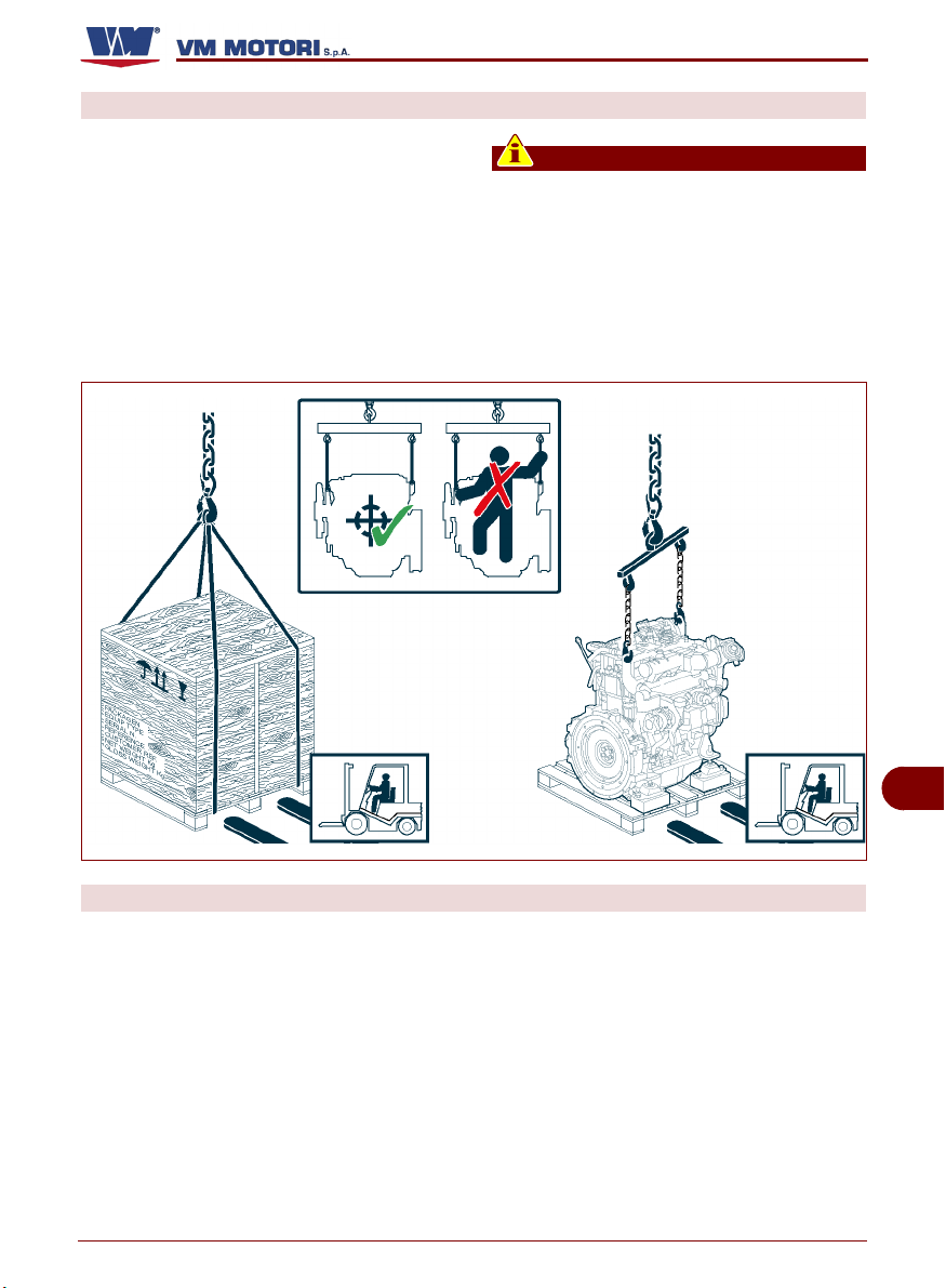
HANDLING AND LIFTING
Secure the engine with a lifting device (lifting beam) of appropriate capacity.
Hook the lifting device to the fixing points as
shown in the figure.
Before carrying out the lifting, identify the
barycentre position of the load.
R750
Important
The brackets of the fixing points have
been designed to lift the engine only
without any additional weight. Do not lift
the engine using a different procedure
from the prescribed one; otherwise, the
warranty for damages will be invalidated.
ENGINE STORAGE
If the engine is left idle for prolonged periods, check the possible conditions of conservation in relation to the storage area and
the type of packaging.
Avoid any environment exposed to damp-
C145300602.fm
ness or to the inclemency of weather.
English
The manufacturer supplies the engine with
a protection treatment which is valid for 6
months from the delivery date.
After the first 6 months, if the engine is not
used, it is necessary to carry out a specific
maintenance to extend the storage period
for a further 6-month period.
The information related to the extension of
the storage period are included in the general warranty conditions.
- 15 -
Handling and installation information
GB
IDM-45300600800.tif
Page 64

INSTALLATION DESIGN
R750
In order to ensure the highest performance
while protecting people, the product itself
and the environment, a full project has to be
developed before carrying out the installation.
The design phase should take into account
the technical data of the engine (see "Specifications") and all the risks which may occur
during its expected lifetime, from installation
to disposal.
During the design and installation phases, it
is advisable to consult the service manual
supplied by VM MOTORI S.P.A.
Further information are available in the website: www.vmmotori.it, in the "Contacts - Request Info" section.
GB
C145300602.fm
English
- 16 -
Handling and installation information
Page 65

OPERATING INFORMATION
RECOMMENDATIONS FOR USE AND OPERATION
R750
The engine has been designed and manufactured to satisfy all the operating conditions indicated by the manufacturer.
Tampering with any device to achieve a dif-
RECOMMENDATIONS FOR USE
The engine is delivered by the factory in the running order. However,
during operation the following indications should be observed:
1- During running-in (first 50 work-
ing hours) and throughout the
engine lifetime, carry out the
maintenance in compliance with
the intervals established by the
manufacturer (see "Engine maintenance").
2 -If the engine is not used regular-
ly, start it after each month of inactivity and run it at minimum
speed until the operating temperature (70÷80°C) is reached.
3 -Avoid using the engine at the highest
speed for prolonged periods during running-in.
4 -When starting the engine for the first
time, run it at no-load for a few minutes
and make sure that the oil pressure value matches the one stated in the table
(see "Specifications" - "Lubrication circuit")
5 -Properly pre-heat the engine when us-
ing it at low temperatures.
When using the engine at low tempera-
C145300602.fm
tures (lower than -10°C), fill it with winter-type fuel.
6 -Use oils and lubricants with suitable fea-
tures (viscosity grade, specifications
and operating temperature) (see "Recommended lubricants").
ferent performance from the intended one
can entail risks for people's safety and
health as well as economic damages.
plug (A)
IDM-45300601800.tif
7- If the "water in fuel" indicator lights up,
proceed as follows:
– Turn off the engine and remove the ig-
nition key.
– Let the engine cool down adequately
to avoid being burnt.
– Prepare a container of appropriate ca-
pacity.
– Unscrew the plug (A) located at the
base of the fuel filter, and leave the
fuel to drain out until there is no more
water in it.
GB
English
- 17 -
Operating information
Page 66

Important
Be careful to ensure that the fuel
in the filter does not drain completely out. If it does, remove it
(see "Oil filter cartridge replacement"), fill it manually and then repeat the bleeding operation.
R750
Warning - Caution
Do not throw away any polluting material in the environment. Carry out
their disposal in compliance with
the relevant legislation in force.
– Screw again the plug (A).
8 -When an alarm signal (visual and/or
acoustic) is triggered by the control panel this indicates that there is a malfunction of some kind.
In the presence of faults, the electronic management system sets the engine to operate in emergency mode,
with automatic limitation of performance.
In these conditions the indicator light
GB
(MIL)
to be dealt with may be malfunction
will light up and the cause
of the engine or the antiparticulate filter.
To solve the problem, proceed as indicated.
– Turn off the engine.
– Consult chapter "Informazioni sui
guasti" for the action to be taken and
plug (A)
IDM-45300601800.tif
details of how to deal with the causes
that triggered the state of emergency.
Warning - Caution
Do not continue to use the engine when
the MIL is on. If the indicator lights up
due to a malfunction in the antiparticulate filter, there may be a risk of fire.
Do not attempt to disconnect the MIL indicator sensor to eliminate the signal.
VM motors will not be liable in any way in
the event of economic damage or risks
for the health and safety of persons.
Important
For further information, please consult
the documentation provided by the manufacturer of the vehicle/device in which
the engine is installed.
C145300602.fm
OPERATING THE ENGINE UNDER SPECIFIC CONDITIONS
The engine performance is affected by fuel
temperature, the temperature and relative
humidity of incoming air and altitude.
When using the engine at high altitudes and
high air and fuel temperatures, the output is
reduced.
For further information contact a
VM MOTORI S.P.A. assistance centre.
English
- 18 -
Operating information
Page 67

ENGINE IGNITION AND TURNING OFF
The engine is not fitted with a control panel.
For information on the commands and control devices, please see the documentation
REFUELLING
R750
provided by the manufacturer of the vehicle/
device in which the engine is installed.
During refuelling, make sure the fuel does
not contain any residue; in this case use
specific filters.
Avoid using fuel mixed with water or other
substances which may damage the engine.
The engine has been designed to be powered by standard fuels available on the European market (according to specifications
DIN EN 590). If it is to be powered by BIODIESEL fuels (according to specifications
UNI EN 14214), it can be mixed, up to 5%,
with fuel available on the European market
(according to regulation DIN EN 590).
Warning - Caution
Do not use fuels with specifications
other than those indicated.
For engines model R754EU4 - R756EU4,
use fuel with a low sulphur content. The percentage sulphur must never exceed 10-50
ppm (parts per million).
Danger - Attention
If the percentage sulphur contained in
the fuel exceeds the value indicated, the
antiparticulate filter will not work properly.
Danger - Attention
All fuels are inflammable. Any fuel leaking or dropping on hot surfaces and
electric components can cause fires. Do
not smoke when refuelling or nearby any
filling station.
GB
C145300602.fm
English
- 19 -
Operating information
Page 68

MAINTENANCE INFORMATION
RECOMMENDATIONS FOR MAINTENANCE
Keep the equipment as much efficient as
possible and carry out the scheduled maintenance operations established by the manufacturer.
A good maintenance will ensure the highest
performance, a longer operating lifetime
and a constant compliance with safety requirements.
Warning - Caution
Unless otherwise stated, all interventions should be carried out when the engine has been stopped, cooled down and
the ignition key has been removed.
Those authorized to carry out these in-
ENGINE MAINTENANCE
The maintenance operations are subdivided
into:
– Maintenance during running-in (first 50
hours)
GB
– Routine maintenance (after running-in)
The frequency stated in the " routine maintenance" table should be applied to engines
which are used regularly.
Some lubricants or components lose their
characteristics over time even if the engine
is left idle for long periods; therefore, main-
R750
terventions should follow all the precautions needed to guarantee the safety of
the people involved, in compliance with
the requirements laid down in the applicable legislation concerning safety at the
workplace.
Important
For each maintenance operation, fill in
the "Periodic maintenance operation
record sheet" provided, so as to keep a
trace of the operations performed and
therefore establish the most suitable
methods for future operations.
tenance intervals should be established
considering that these parts need to be replaced not only on the basis of their hours of
operation but of ageing as well.
The approximate maximum time during
which the chemical-physical characteristics
of a few components or lubricants are maintained is stated below.
– 1 year: Lubricant oil
– 1 year: Fuel filter cartridge
– 2 years: Coolant
C145300602.fm
English
- 20 -
Maintenance information
Page 69

Maintenance during running-in table (first 50 hours)
Important
For each maintenance operation, fill in
the "Periodic maintenance operation
record sheet" provided, so as to keep a
(1)
Frequency
Every
10 hours
(every day)
After the first
50 hours (at
the end of
running-in)
Component Type of intervention Intervention procedures Reference
Engine oil
Coolant
Air filter Check it is clean
Coolant fluid radiator
Oil filter Replacement
(2)
(4)
Level control Top up, if necessary
Level control Top up, if necessary
Check it is clean Clean with a soft brush
trace of the operations performed and
therefore establish the most suitable
methods for future operations.
Clean with low pressure compressed air.
Replace, if necessary
R750
See "Engine oil level
control"
See "Engine coolant
level check"
See "Oil filter cartridge
replacement"
Routine maintenance table (after running-in)
Important
For each maintenance operation, fill in
the "Periodic maintenance operation
record sheet" provided, so as to keep a
(1)
Frequency
Every
10 hours
C145300602.fm
Every
300 hours
English
Component Type of intervention Intervention procedures Reference
Engine oil
Coolant
Air filter Check it is clean
Coolant fluid radiator
Engine oil
Oil filter
(2)
(4)
(2)
Level control Top up, if necessary
Level control Top up, if necessary
Check it is clean Clean with a soft brush
Replacement
Replace the cartridge
trace of the operations performed and
therefore establish the most suitable
methods for future operations.
See "Engine oil level
control"
See "Engine coolant
level check"
Clean with low pressure
compressed air.
Replace, if necessary
See "Engine oil
change"
See "Oil filter cartridge replacement"
- 21 -
Maintenance information
GB
Page 70

R750
(1)
Frequency
Every
300 hours
(Every 30.000
km)
Every
900 hours
Every
1200 hours
Every
1500 hours
(Every 50.000
km)
Every
4000 hours
Every
8000 hours
(1) If an hour counter is not available, the frequency of the interventions should be calculated on the basis of a calendar
day: one calendar day corresponds to 12 hours of operation.
(2) In severe working conditions, such as dusty environments and operation at extreme loads, the engine oil must be
changed every 150 working hours. If the engine has not been in operation for the length of time indicated, the oil must
still be changed at least once a year.
(3) If the engine has not been in operation for the length of time indicated, the filter must still be changed at least once
every 12 months.
(4) If the engine has not been in operation for the length of time indicated, the fluid must still be changed at least once
every 24 months.
(5) If the engine has not been in operation for the length of time indicated, the belt must still be changed at least once
every 24 months
Component Type of intervention Intervention procedures Reference
Fuel filter
Drive belt (type
Poly-V)
Coolant
(3)
(5)
(4)
Replace
Replace
Replace
Antiparticulate filter Clean
Engine
Engine
Performing partial
overhaul
Performing general
overhaul
Apply to an authorised
workshop
Apply to an authorised
workshop
See "Fuel filter
replacement"
See "Belt replacement (type Poly-V)"
See "Coolant
replacement"
See "Cleaning the
antiparticulate filter"
GB
C145300602.fm
English
- 22 -
Maintenance information
Page 71

Periodic maintenance operation record sheet
Important
For each maintenance operation, fill in
the sheet, so as to keep a trace of the operations performed and therefore estab-
R750
lish the most suitable methods for future
operations.
Date
Hours
(1)
Type of maintenance performed Signature and stamp of workshop
..........................................................................
..........................................................................
..........................................................................
..........................................................................
..........................................................................
..........................................................................
_____ _____ _____________________________________ ________________
..........................................................................
..........................................................................
..........................................................................
..........................................................................
..........................................................................
..........................................................................
_____ _____ _____________________________________ ________________
..........................................................................
..........................................................................
..........................................................................
C145300602.fm
..........................................................................
..........................................................................
..........................................................................
_____ _____ _____________________________________ ________________
GB
(1) Indicate the total number of working hours.
English
- 23 -
Maintenance information
Page 72

R750
GB
Date
Hours
(1)
Type of maintenance performed Signature and stamp of workshop
..........................................................................
..........................................................................
..........................................................................
..........................................................................
..........................................................................
..........................................................................
_____ _____ _____________________________________ ________________
..........................................................................
..........................................................................
..........................................................................
..........................................................................
..........................................................................
..........................................................................
_____ _____ _____________________________________ ________________
..........................................................................
..........................................................................
..........................................................................
..........................................................................
..........................................................................
..........................................................................
_____ _____ _____________________________________ ________________
..........................................................................
..........................................................................
..........................................................................
..........................................................................
..........................................................................
..........................................................................
_____ _____ _____________________________________ ________________
..........................................................................
..........................................................................
C145300602.fm
..........................................................................
..........................................................................
..........................................................................
..........................................................................
_____ _____ _____________________________________ ________________
(1) Indicate the total number of working hours.
English
- 24 -
Maintenance information
Page 73

R750
Date
Hours
(1)
Type of maintenance performed Signature and stamp of workshop
..........................................................................
..........................................................................
..........................................................................
..........................................................................
..........................................................................
..........................................................................
_____ _____ _____________________________________ ________________
..........................................................................
..........................................................................
..........................................................................
..........................................................................
..........................................................................
..........................................................................
_____ _____ _____________________________________ ________________
..........................................................................
..........................................................................
..........................................................................
..........................................................................
..........................................................................
..........................................................................
_____ _____ _____________________________________ ________________
..........................................................................
..........................................................................
..........................................................................
..........................................................................
..........................................................................
..........................................................................
_____ _____ _____________________________________ ________________
..........................................................................
..........................................................................
C145300602.fm
..........................................................................
..........................................................................
..........................................................................
..........................................................................
_____ _____ _____________________________________ ________________
GB
(1) Indicate the total number of working hours.
English
- 25 -
Maintenance information
Page 74

R750
GB
Date
Hours
(1)
Type of maintenance performed Signature and stamp of workshop
..........................................................................
..........................................................................
..........................................................................
..........................................................................
..........................................................................
..........................................................................
_____ _____ _____________________________________ ________________
..........................................................................
..........................................................................
..........................................................................
..........................................................................
..........................................................................
..........................................................................
_____ _____ _____________________________________ ________________
..........................................................................
..........................................................................
..........................................................................
..........................................................................
..........................................................................
..........................................................................
_____ _____ _____________________________________ ________________
..........................................................................
..........................................................................
..........................................................................
..........................................................................
..........................................................................
..........................................................................
_____ _____ _____________________________________ ________________
..........................................................................
..........................................................................
C145300602.fm
..........................................................................
..........................................................................
..........................................................................
..........................................................................
_____ _____ _____________________________________ ________________
(1) Indicate the total number of working hours.
English
- 26 -
Maintenance information
Page 75

MAINTENANCE WHEN THE ENGINE IS LEFT IDLE
If the vehicle/equipment to which the engine
is fitted remains inactive, certain maintenance operations must be carried out to ensure the engine remains in full working
order.
If the engine is not used for short periods of
time, carry out the following interventions:
1- Make sure the electric contacts are
working properly and, if necessary, protect them with an anti-oxidant spray.
2 -Check the charge of the battery and the
liquid level.
3 -If necessary, carry out the scheduled
maintenance work (see "Engine maintenance")
ENGINE PROTECTIVE TREATMENT
Follow the procedure below.
1- Check the engine oil and coolant level.
2- Fill the service tank with a mixture made
up of 10% protective oil (Castrol Safecoat DW30X, Rustilo 181, Rustilo
DWX31) and 90% fuel.
Important
This operation can be carried out using
an additional tank fitted with couplings
connecting it to the engine fuel supply
circuit.
3- Disconnect all the mechanical parts and
auxiliary applications from the engine as
they could be damaged by running it at
no-load.
C145300602.fm
4- Start the engine and run it at minimum
speed for 5 minutes.
5- Bring the engine to 1500÷1800 rpm for
15 minutes until the operating temperature (70÷80°C) is reached.
6- Turn off the engine and remove the igni-
R750
It is advisable to start the engine bringing it
to the operating temperature (70÷80°C) at
least once per month.
The engine must be started once per month
if it is installed for emergency purposes.
If the engine is left idle for prolonged periods, carry out the engine protective treatment to guarantee its efficiency for 6 months
and to avoid continuous control and maintenance interventions. If the engine is not
used for a further period of time, check the
need to repeat the protective treatment for
other 6 months (see "Engine protective
treatment").
tion key.
7- Let the engine cool down adequately to
avoid being burnt.
8- Protect the electric contacts with an anti-
oxidant spray.
9- Protect the engine with waxes and/or a
synthetic resin anti-oxidant spray.
10-Disconnect the terminals of the battery.
11-Fill up the fuel tank.
12-Loosen the transmission belt to guaran-
tee it a longer life (see "Procedure for
loosening or tensioning the belt (type
Poly-V)")
13-Make sure the engine is sheltered from
weather agents.
GB
English
- 27 -
Maintenance information
Page 76

MAINTENANCE IN CASE OF ENGINE INACTIVITY
After a period of inactivity, it is necessary to
– Replace the air filter according to the es-
carry out a few maintenance interventions
before starting the engine again to ensure
its maximum efficiency conditions.
– Tension again the transmission belt (see
– Check the charge of the battery and the
liquid level.
– Make sure the electric contacts are intact
– Check the tightening of the hydraulic un-
and properly working.
– Carry out the operation diagnosis of the
engine
– Check the rubber gaskets and relevant
– Check the oil level, and, if necessary, top
up or replace it according to the established intervals (see "Routine mainte-
– Use a cloth soaked in a degreasing prod-
nance table (after running-in)").
– Replace the oil filter according to the es-
tablished intervals (see "Routine mainte-
– Start the engine and run it at minimum
nance table (after running-in)n")
– Check the coolant level, and if neces-
sary, top up or replace it according to the
– If no anomalies are detected, bring the
established intervals (see "Routine maintenance table (after running-in)")
– Replace the fuel filter according to the es-
– Turn off the engine and check again the
tablished intervals (see "Routine maintenance table (after running-in)")
R750
tablished intervals (see "Routine maintenance table (after running-in)")
"Procedure for loosening or tensioning
the belt (type Poly-V)")
ions (see "Control screw tightening and
union sealing")
fixing clips to ensure they are undamaged.
uct to remove the external protective
treatment.
speed for a few minutes (see "Engine ignition and turning off")
engine to its operating temperature
(70÷80°C).
engine oil and coolant level.
GB
CHECKS AND CONTROLS
The list indicates some of the maintenance,
testing and control operations to be carried
out on the engine during normal operation.
– Fuel supply circuit bleeding
– Control screw tightening and union sealing
– Engine oil level control
– Engine coolant level check
C145300602.fm
– Procedure for loosening or tensioning the
belt
– Engine oil change
– Coolant replacement
– Oil filter cartridge replacement
English
– Fuel filter replacement.
– Cleaning the antiparticulate filter
Important
For each maintenance operation, fill in
the "Periodic maintenance operation
record sheet" provided, so as to keep a
trace of the operations performed and
therefore establish the most suitable
methods for future operations.
- 28 -
Maintenance information
Page 77

FUEL SUPPLY CIRCUIT BLEEDING
Important
This operation must be carried
out each time the fuel cartridge is
changed
Follow the procedure below.
1- Turn off the engine and remove
the ignition key.
2- Let the engine cool down ade-
quately to avoid being burnt.
3- Prepare a container of appropri-
ate capacity.
4- Loosen the screw (E).
5- Operate the pump (F) manually
to eliminate air from the circuit.
6- Check that a flow of clean fuel contain-
ing no air bubbles is coming out of the
bleeder screw (E).
Important
Be careful to ensure that the fuel in the
filter does not drain completely out. If it
does, remove it (see "Fuel filter replace-
R750
pump (G)
bleeding screw (E)
IDM-45300600900.tif
ment"), fill it manually and then repeat
the bleeding operation.
7- Tighten the screw (E).
8- Wipe out the fuel residues before start-
ing the engine.
CONTROL SCREW TIGHTENING AND UNION SEALING
Follow the procedure below.
1- Start the engine and run it at minimum
speed for a few minutes.
2- Run the engine at normal speed until the
operating temperature (70÷80°C) is
reached.
4- Make sure the fixing screws of the main
parts are tightened properly.
5- Check the union sealing on the fuel sup-
ply circuit.
6- Check the tightening of the clamps.
7- Check any fluid leaks.
3- Turn off the engine and let it cool down.
C145300602.fm
English
- 29 -
GB
Maintenance information
Page 78

ENGINE OIL LEVEL CONTROL
Follow the procedure below.
1- Start the engine and bring it to
the operating temperature
(70÷80 °C).
2- Turn off the engine and remove
the ignition key.
3- Place the engine on a perfectly
level surface.
4- Wait a few minutes so that all the
oil will flow into the sump.
5- Remove the dipstick (L) and
check the oil level.
6- Top up, if necessary, from plug
(M). As for the oil quantity, see
"Specifications".
Important
The oil level should be included
between the minimum and maximum marks. Do not mix oils of different brands or with different
features (see "Recommended lubricants").
dipstick (L)
R750
load plug (M)
IDM-45300601000.tif
ENGINE COOLANT LEVEL CHECK
Follow the procedure below.
GB
1- Start the engine and bring it to
the operating temperature
(70÷80 °C).
2- Turn off the engine and remove
the ignition key.
3- Let the engine cool down proper-
ly.
4- Unscrew the filler plug (P).
Warning - Caution
Open the plug gently to drain the
C145300602.fm
pressure.
English
- 30 -
load plug (P)
IDM-45300601100.tif
Maintenance information
Page 79

5- Top up, if necessary, from plug
(P). As for the liquid quantity and
type, see "Specifications".
Important
load plug (P)
The fluid level must be up to the
base of the neck into which the radiator plug is screwed. For further
information, please consult the
documentation provided by the
manufacturer of the vehicle/device in which the engine is installed.
`
PROCEDURE FOR LOOSENING OR TENSIONING THE BELT (TYPE POLY-V)
Follow the procedure below.
1- Turn off the engine and remove
the ignition key.
2- Let the engine cool down ade-
quately to avoid being burnt.
To loosen the belt: turn the tensioner
(A) anticlockwise until holes (B) correspond. When holes correspond,
lock the tensioner with pin (C).
To tighten the belt: adjust the tensioner (A) to extract the pin (C). Relea-
tensioner (A)
se the tensioner so as to restore the
required tension in the belt.
R750
IDM-45300601100.tif
GB
Warning - Caution
C145300602.fm
Before tightening the belt, make
sure that it is correctly positioned
in the pulley seats (see "Belt replacement (type Poly-V)").
English
- 31 -
pin (C)
hole (B)
IDM-45300601200.tif
Maintenance information
Page 80

ENGINE OIL CHANGE
Follow the procedure below.
1- Turn off the engine and remove
the ignition key.
2- Let the engine cool down ade-
quately to avoid being burnt.
3- Prepare a container of appropri-
ate capacity.
As for the oil quantity, see "Specifications".
4- Unscrew the load plug (M).
5- Unscrew the exhaust plug (Q)
and let all the oil flow into the
container.
6- Replace the gasket and screw
plug (Q) back into place.
R750
load plug (M)
Important
Lock the plug to a torque of 55 Nm.
7- Pour the new oil until it reaches
the correct level on the dipstick
(see "Engine oil level control").
8- Screw again the load plug (M).
9- Start the engine and bring it to the oper-
ating temperature (70÷80 °C).
Check for any oil leaks
GB
Warning - Caution
If any oil leaks are found, stop the engine
immediately and contact an authorised
service centre.
C145300602.fm
drain plug (Q)
IDM-45300601300.tif
10-Turn off the engine and check the oil lev-
el (see "Engine oil level control").
Important
Do not throw the oil in the environment
but carry out its disposal in compliance
with legislation in force in the country
where it is used.
Use the oils and lubricators recommended by the manufacturer (see "Recommended lubricants").
English
- 32 -
Maintenance information
Page 81

COOLANT REPLACEMENT
Follow the procedure below.
1- Start the engine and run it at min-
imum speed for a few minutes.
The cooling circuit reaches the
operating pressure.
2- Turn off the engine and remove
the ignition key.
3- Let the engine cool down ade-
quately to avoid being burnt.
4- Prepare a container of appropri-
ate capacity.
As for the liquid quantity, see
"Specifications".
5- Unscrew the load plug (P).
Warning - Caution
Open the plug gently to drain the
pressure.
6- Open the cock (S).
Important
If there is no coolant drainage tap, check
to see if there is a drain plug. For further
information, please consult the documentation provided by the manufacturer
of the vehicle/device in which the engine
is installed.
7- Let the liquid flow into the container.
8- Close the cock (S).
9- Pour in the new liquid.
Important
The fluid level must be up to the base of
the neck into which the radiator plug is
screwed. If there is a coolant expansion
C145300602.fm
tank, consult the documentation provided by the manufacturer of the vehicle/device in which the engine is installed.
As for the liquid quantity and type, see
"Specifications".
10-Screw again the plug (P).
R750
load plug (P)
cock (S)
IDM-45300601400.tif
11-Turn the engine on and keep it running
at idle speed for a few minutes to bring it
up to working temperature (70÷80°C).
Important
If the fluid level decreases, top it up until
it is constantly between the reference
marks
12-Turn off the engine and let it cool down
properly.
13-Check the coolant level and, if neces-
sary, carry out topping-up (see "Engine
oil level control")
Important
Do not throw away any polluting material
in the environment. Carry out their disposal in compliance with the relevant
legislation in force.
GB
English
- 33 -
Maintenance information
Page 82

OIL FILTER CARTRIDGE REPLACEMENT
Follow the procedure below.
1- Turn off the engine and remove
the ignition key.
2- Let the engine cool down ade-
quately to avoid being burnt.
3- Prepare a container to collect
any leak.
4- Unscrew the filter (U) and re-
place it.
5- Check the conditions of gasket
(V) and, if necessary, replace it.
6 -Lubricate the seal of the new car-
tridge before assembling it.
7- Install the oil filter.
Important
Lock the screw to a torque of 25 Nm.
8- Turn the engine on and keep it running
at idle speed for a few minutes to bring it
up to working temperature (70÷80°C).
9 -Turn off the engine and remove the igni-
tion key.
10-Wait a few minutes so that all the oil will
GB
flow into the sump.
11-Check that the oil in the tank is at the
correct level, and top up if necessary
(see "Controllo livello olio motore").
R750
gasket (V)
filter (U)
IDM-45300601500.tif
12-Check for any oil leaks
Warning - Caution
If any oil leaks are found, stop the engine
immediately and contact an authorised
service centre.
Important
Do not throw away any polluting material
in the environment. Carry out their disposal in compliance with the relevant
legislation in force.
C145300602.fm
English
- 34 -
Maintenance information
Page 83

FUEL FILTER REPLACEMENT
Follow the procedure below.
1- Turn off the engine and remove
the ignition key.
2- Let the engine cool down ade-
quately to avoid being burnt.
3- Prepare a container to collect
any leak.
4- Disassemble filter (Z) and re-
place it.
5- Fill the new filter with fuel from
the filter you have just removed.
6- Lubricate the gasket of the new
filter before mounting it.
7- Refit the filter.
8- Bleed air from the fuel supply circuit
(see "Fuel supply circuit bleeding").
9- Turn the engine on and check for any
fuel leaks.
R750
fuel filter (Z)
IDM-45300601600.tif
Warning - Caution
If any fuel leaks are found, stop the engine immediately and contact an authorised service centre.
Important
Do not throw away any polluting material
in the environment. Carry out their disposal in compliance with the relevant
legislation in force.
C145300602.fm
English
- 35 -
GB
Maintenance information
Page 84

CLEANING THE ANTIPARTICULATE FILTER
f
Follow the procedure below.
Provide the equipment and protective clothing listed.
– Compressed air gun 5÷7 bar
– industrial type vacuum cleaner or
dust collection device
– individual safety devices (gloves,
goggles, face mask)
1- Turn off the engine and remove
the ignition key.
2- Let the engine cool down ade-
quately to avoid being burnt.
Warning - Caution
It is compulsory to wear all the individual safety devices foreseen
for protection of the hands from
contact with harmful substances
(gloves), the respiratory tract
(protective face masks) and the eyes
(goggles).
3- Disconnect the gas inlet and exhaust
pipes from the filter.
4- Before removing the filter , mark the side
connecting to the manifold (gas inlet), so
GB
that it is replaced in the opposite position
to the one in which it was originally fitted.
5- Loosen the clamps (A) and remove the
centre body of the filter.
6- Connect the vacuum cleaner to the filter
gas inlet area.
7 -Blow air (5 - 7 bar) from the opposite
side into the filter for approximately
30÷40 minutes.
Important
C145300602.fm
Move the compressed air gun slowly, directing it into each cell of the filter to
clean it thoroughly. Keep a distance of
10 cm between the jet of air and the surface of the filter.
Do not clean the filter with steam and/or
other detergents. The use of these prod-
R750
clamp (A)
centre body
IDM-45300601901.ti
ucts may damage and/or deteriorate the
filter.
Warning - Caution
Do not throw away any polluting material
in the environment. Carry out their disposal in compliance with the relevant
legislation in force.
8 -Remove and replace the clamps (A) with
new original spare parts.
Important
When requesting any components for
the antiparticulate filter, always contact
your nearest VM MOTORI workshop or
Dinex distributor. When ordering, provide the details indicated on the identification plate affixed to the filter.
9 -Fit the filter in the opposite direction to its
original position. The side marked as
above must be connected to the exhaust
pipe.
10-Tighten the clamps to a torque of 30 Nm.
English
- 36 -
Maintenance information
Page 85

RECOMMENDED LUBRICANTS
The lubricant recommended by
VM MOTORI S.P.A. is:
Q8 FORMULA ADVANCED DIESEL
10W-40 for operating temperatures
from -20°C to +50°C.
Oils of different brands can be used
provided that they have the following
features:
R750 IE3 R750 EU4
Gradazione SAE 10W-40 SAE 10W-40
Specifiche minime
API CF, CF-4, CG-4, CH-4, CI-4
ACEA A3/B4
API CF-4, CG-4, CH-4, CI-4
ACEA A3/B4
Important
It is advisable not to mix oils with different characteristics.
R750
IDM-45300302500.tif
C145300602.fm
English
- 37 -
GB
Maintenance information
Page 86

INFORMATION ABOUT FAILURES
TROUBLESHOOTING
The information below are provided to facilitate the identification and solution of possible anomalies and failures which may occur
during operation. Some of these problems
can be solved by the user, while others require specific technical skills or abilities,
therefore they should be exclusively dealt
with by qualified technicians with extensive
experience in the specific sector of intervention.
Problem Cause Remedy
During the ignition
phase the control board
and the engine do not
start.
The engine does not
start
The starter motor runs
idle
GB
The starter motor is not
running
The engine stops after
ignition
C145300602.fm
Flat battery Recharge or replace battery
Blown fuse Replace fuse
The electric cables are disconnected or
they do not guarantee continuity
Failure of engine revolution sensor
Presence of air in the fuel supply circuit
Dirty or faulty injectors
Faulty fuel pressure regulation valve
Failure of the start control
Water and/or impurities in the fuel Apply to an authorised workshop
Clogged fuel filter
Electromagnet failure
Flat battery Recharge or replace battery
Interrupted electric connection Check the electric connections
Worn brushes
Presence of air in the fuel supply circuit
Clogged fuel filter
Injection pump malfunction Apply to an authorised workshop
Faulty fuel pressure regulation valve
Presence of air in the fuel supply circuit
Water and/or impurities in the fuel Apply to an authorised workshop
The electric cables are disconnected or
they do not guarantee continuity
R750
Warning - Caution
Activation of a visual and/or acoustic
signal indicates some form of malfunction. In this case, turn the engine off immediately and consult the
documentation supplied by the manufacturer of the vehicle/device in which the
engine is installed.
Check the electric connections
Replace the sensor
Apply to an authorised workshop
Carry out bleeding (see "Fuel supply circuit
bleeding")
Replace the injectors
Apply to an authorised workshop
Replace the valve
Apply to an authorised workshop
Replace the start control
Apply to an authorised workshop
Replace filter (see "Fuel filter replacement")
Check the starter motor
Apply to an authorised workshop
Replace the worn brushes
Apply to an authorised workshop
Carry out bleeding (see "Fuel supply circuit
bleeding")
Replace filter (see “Fuel filter replacement”)
Replace the valve
Apply to an authorised workshop
Carry out bleeding (see “Fuel supply circuit
bleeding”).
Check the electric connections
English
- 38 -
Information about failures
Page 87

R750
Problem Cause Remedy
Clogged fuel filter
Presence of air in the fuel supply circuit
The engine does not
reach the operating
speed
Emission of black
smoke from the exhaust pipe
Light emission of white
smoke from the exhaust pipe
Abundant emission of
white smoke from the
exhaust pipe
The pressure
gauge shows a
too low engine
oil pressure and
the corresponding warning light
comes on
The coolant temperature warning light comes
on
C145300602.fm
Injection pump malfunction Apply to an authorised workshop
Dirty or faulty injectors
Water and/or impurities in the fuel Apply to an authorised workshop
Clogged air filter Clean or replace the filter
Insufficient combustion air flow Apply to an authorised workshop
Engine overheating Apply to an authorised workshop
Overload Reduce the load
Dirty or faulty injectors
Faulty turbocharging turbine
Oil level too high Adjust the oil level
Worn segments
Worn valve guideways
Burnt gasket head Apply to an authorised workshop
Water pump malfunction
Replace the belt See “Belt replacement (type Poly-V)”
Thermostat valve malfunction
Coolant too low
Failure of pressure gauge
Oil level too low
Oil pump failure
Faulty sensor
Engine oil filter blocked
Coolant too low
Stucked overpressure valve of the load
plug
Water pump malfunction
Thermostat valve malfunction
Broken or worn belt
Replace filter (see “Fuel filter replacement”)
Carry out bleeding (see “Fuel supply circuit
bleeding”)
Replace the injectors
Apply to an authorised workshop
Replace the injectors
Apply to an authorised workshop
Replace the turbine
Apply to an authorised workshop
Check compression
Apply to an authorised workshop
Check wear
Apply to an authorised workshop
Replace the pump
Apply to an authorised workshop
Replace the valve
Apply to an authorised workshop
Top up, if necessary (see “Engine coolant
level check”)
Check or replace the pressure gauge
Apply to an authorised workshop
Adjust the oil level (see “Engine oil level
control”)
Check or replace the pump
Apply to an authorised workshop
Check and, if appropriate, replace the sensor.
Apply to an authorised workshop
Replace the engine oil filter (see “Oil filter
cartridge replacement”)
Adjust the engine coolant level (see “Engine coolant level check”)
Replace the plug
Replace the pump
Apply to an authorised workshop
Replace the valve
Apply to an authorised workshop
Replace the belt (see “Belt replacement
(type Poly-V)”)
GB
English
- 39 -
Information about failures
Page 88

R750
Problem Cause Remedy
Clogged fuel filter
Presence of air in the fuel supply circuit
Output reduction
The battery
warning light
comes on
The oil pressure
warning light
comes on
The warning
light which detects water in
fuel comes on
The engine indicator light (MIL)
comes on
Injection pump malfunction
Dirty or faulty injectors
Clogged air filter Clean or replace the filter
Engine overheating Apply to an authorised workshop
Insufficient combustion air flow Apply to an authorised workshop
The alternating current generator does
not charge the battery
Engine oil pressure too low Apply to an authorised workshop
Presence of water in the fuel filter
Electronic engine management does not
work properly
Engine malfunction Apply to an authorised workshop
Antiparticulate filter blockedo
Replace filter (see “Fuel filter replacement”)
Carry out bleeding (see “Fuel supply circuit
bleeding”)
Replace the pump
Apply to an authorised workshop
Replace the injectors
Apply to an authorised workshop
Check and, if appropriate, replace the alternating current generator
Apply to an authorised workshop
Replace filter (see “Fuel filter replacement”)
Apply to an authorised workshop
Clean or replace the filter (see "Cleaning the
antiparticulate filter")
GB
C145300602.fm
English
- 40 -
Information about failures
Page 89

INFORMATION ABOUT COMPONENT REPLACEMENT
RECOMMENDATIONS FOR PART REPLACEMENT
Before carrying out any replacement, activate all safety devices and evaluate the
need to inform the personnel working on the
engine or nearby. In particular, place proper
signs in the nearby areas and keep away all
devices which, once activated, may represent a source of unexpected danger and
risk for people's safety and health. When
necessary, replace the worn components,
and use original spare parts only. The manufacturer cannot be held responsible for
damages to people or components resulting
from the use of non original spare parts and
from repairs carried out without the authorisation of the manufacturer.
When requesting spare parts, always contact your nearest VM MOTORI S.P.A. spare
parts centre (see "Documentation enclosed": Spare parts and service centre address booklet), indicating the engine serial
number (see "Manufacturer and engine
identification").
BELT REPLACEMENT (TYPE POLY-V)
Follow the procedure below.
3- Turn the tensioner (A) anticlockwise to
1- Turn off the engine and remove the igni-
tion key.
2- Let the engine cool down adequately to
4- Remove the belt (D) and replace it.
avoid being burnt.
R750
loosen the belt. When holes (B) corre-
spond, lock the tensioner with pin (C).
C145300602.fm
English
belt (D)
belt (D)
- 41 -
GB
belt (D)
pin (C)
tensioner (A)
hole (B)
IDM-45300301700.tif
Information about component replacement
Page 90

R750
5 -Adjust the tensioner (A) to extract the
pin (C). Release the tensioner so as to
restore the required tension in the belt.
Important
Before tightening the belt, make sure
that it is correctly positioned in the pulley seats.
belt (D)
Warning - Caution
Do not throw away any replaced part in
the environment. Carry out their disposal
in compliance with the relevant legislation in force.
Important
Before restarting the engine, make sure
there are no tools or other material left
near the moving parts.
belt (D)
pin (C)
tensioner (A)
GB
belt (D)
ENGINE DISPOSAL
This operation should be carried out by experienced operators, in compliance with the
legislation in force concerning safety at the
workplace.
C145300602.fm
Do not throw away non bio-degradable
products and non ferrous components (rubber, PVC, resins, etc.).
English
hole (B)
While decommissioning the engine, divide
all the components depending on their
chemical composition and dispose of them
accordingly.
- 42 -
Information about component replacement
IDM-45300301700.tif
Page 91

ANALYTIC INDEX
A
Antiparticulate filter, cleaning the, 36
Assistance, procedure to request, 4
Attached documentation, 5
B
Belt replacement (type Poly-V), 41
C
Checks and controls, 28
Cleaning the antiparticulate filter, 36
Control screw tightening and union sealing, 29
Coolant replacement, 33
Coupling sealing and screw tightening, control, 29
E
Engine coolant level check, 30
Engine disposal, 42
Engine general description, 6
Engine ignition and turning off, 19
Engine inactivity, maintenance in case of, 27
Engine maintenance, 20
Engine oil change, 32
Engine oil level control, 30
Engine protective treatment, 27
Engine storage, 15
Engine, protective treatment, 27
Environmental impact, safety rules for, 11
F
Fuel filter replacement, 35
Fuel supply circuit bleeding, 29
H
Handling and installation, recommendations for, 13
Handling and lifting, 15
I
In case of engine inactivity, maintenance, 28
Installation and handling, recommendations for, 13
Installation design, 16
Introduction, 2
L
Lifting and handling, 15
Loosen or tension the belt, procedures to, 31
M
Maintenance in case of engine inactivity, 28
Maintenance when the engine is left idle, 27
Maintenance, recommendations for, 20
R750
Manual, purpose of the, 3
Manufacturer and engine identification, 4
Manufacturer and engine, identification, 4
O
Oil filter cartridge replacement, 34
Operating the engine under specific conditions, 18
Operation and use, recommendations, 17
P
Packaging and transport, 13
Part replacement, recommendations for, 41
Procedure for loosening or tensioning the belt, 31
Procedure to request technical assistance, 4
Purpose of the manual, 3
Q
Quality system certificate ISO 9001 -QS 9000-ISO
14001, 2
R
Recommendations for handling and installation, 13
Recommendations for maintenance, 20
Recommendations for part replacement, 41
Recommendations for use, 17
Recommendations for use and operation, 17
Recommended lubricants, 37
Refuelling, 19
Request assistance, procedure to, 4
Residual risks, 12
S
Safety rules, 10
Safety rules for the environmental impact, 11
Screw tightening and coupling sealing, control, 29
Specifications, 8
T
Tension or loosen, procedure to, 31
Transport and packaging, 13
Troubleshooting, 38
Turning off engine, stop, 19
U
Unpacking, 14
Use and operation, recommendations, 17
Use, recommendations for, 17
W
Warranty conditions, 5
GB
C145300602.fm
English
- 43 -
Analytic index
Page 92

Page 93

ALLGEMEINES INHALTSVERZEICHNIS
R750
ALLGEMEINE INFORMATIONEN
Einleitung........................................................... 2
Zertifizierung des Qualitätssystems ISO 9001 -
QS 9000 ISO 14001 .......................................... 2
Zweck des Handbuchs ......................................3
Bezeichnung von Hersteller und Motor ............. 4
Vorgehensweise zur Anforderung des
Kundendienstes................................................. 4
Garantiebedingungen ........................................ 5
Beiliegende Dokumentation............................... 5
TECHNISCHE DATEN
Allgemeine Beschreibung des Motors ............... 6
Technische Daten.............................................. 8
INFORMATIONEN ZUR SICHERHEIT
Vorgaben zur Sicherheit.................................. 10
Vorgaben zur Sicherheit beim Einfluss auf die
Umwelt............................................................. 11
Restrisiken....................................................... 12
INFORMATIONEN ZUR UMSETZUNG UND
INSTALLATION
Empfehlungen zur Umsetzung und
Installation ....................................................... 13
Verpackung und Transport .............................. 13
Entfernen der Verpackung............................... 14
Umsetzung und Anheben................................ 15
Lagern des Motors........................................... 15
Planung der Installation................................... 16
GEBRAUCHSHINWEISE
Empfehlungen zu Gebrauch und
Funktionsweise................................................ 17
Gebrauchsempfehlungen ................................17
Funktionsweise des Motors unter besonderen
Bedingungen ................................................... 18
Ein- und Ausschalten des Motors.................... 19
Nachfüllen von Treibstoff................................. 19
INFORMATIONEN ZUR WARTUNG
Empfehlungen zur Wartung .............................20
Wartung des Motors.........................................20
Wartung im Falle des Stillstands des
Motors ..............................................................27
Schutzbehandlung des Motors.........................27
Wartung bei erneuter Inbetriebnahme des
Motors ..............................................................28
Tests und Kontrollen ........................................28
Entlüftung des Speisleitungskreises ................29
Prüfen Sie die Festigkeit der Schrauben und die
Dichtheit der Anschlüsse..................................29
Prüfen Sie den Motorölstand............................30
Prüfen Sie den
Motorkühlflüssigkeitsstand...............................30
Vorgehensweise zum Lockern oder Spannen des
Riemens (Typ Poly-V)......................................31
Motorölwechsel ................................................32
Wechsel der Kühlflüssigkeit .............................33
Wechsel der Ölfiltereinsatz ..............................34
Wechsel des Treibstofffilters............................35
Reinigung Partikelfilter .....................................36
Empfohlene Schmiermittel ...............................37
INFORMATIONEN ZU STÖRUNGEN
Störungssuche .................................................38
INFORMATIONEN ZUM AUSTAUSCH DER
BAUTEILE
Empfehlungen zum Austausch von
Bauteilen ..........................................................41
Austausch des Riemens (typ Poly-V)...............41
Entsorgung des Motors....................................42
ANALYTISCHES INHALTSVERZEICHNIS ....43
DE
C145300602.fm
Deutsch
- 1 -
Allgemeines Inhaltsverzeichnis
Page 94

ALLGEMEINE INFORMATIONEN
EINLEITUNG
Sehr geehrter Kunde, wir möchten Ihnen danken, sich für die VM MOTORI S.P.A. beim
Kauf Ihres Motors entschieden zu haben.
Unser Kundendienst- und Ersatzteilbereich
wurde zusätzlich verstärkt, um unsere Kunden noch besser bedienen zu können.
Nur bei Einsatz von Original-Ersatzteilen
und unter Hinzuziehung unseres Fachpersonals ist es möglich, die Aufrechterhaltung
der besten Leistung des von Ihnen erworbenen Motors zu gewährleisten.
Erlauben Sie uns also, Ihnen zu raten, sich
hinsichtlich der Wartung des von der VM
MOTORI S.P.A. hergestellten Motors AUS-
SCHLIESSLICH an unseren Technischen
Kundendienst und Ersatzteilservice zu wenden.
Falls die Reparatur der von VM MOTORI
S.P.A. entwickelten und gebauten Moto-
R750
ren durch nicht autorisierte Techniker erfolgt, falls die vorgesehenen
planmäßigen Wartungsarbeiten nicht
durchgeführt werden, falls NICHT-ORIGINALERSATZTEILE verwendet werden,
falls das Nachfüllen der Kühlflüssigkeiten, Motoröle und Kraftstoffe nicht gemäß
den Herstellerangaben erfolgt, erlischt
sofort jegliche Verpflichtung zu Garantieleistungen und technischem Kundendienst seitens der VM MOTORI S.P.A.
Wir sind uns gewiss, dass Sie die Bedeutung der Einhaltung der oben genannten
Festlegung unter technischem Profil verstehen werden, mit der Zweck verfolgt wird, vor
allem zu verhindern, dass unsere Kunden
negative Erfahrungen machen.
Wir stehen gern zu Ihrer Verfügung und verbleiben bei dieser Gelegenheit mit höflichen
Grüßen.
ZERTIFIZIERUNG DES QUALITÄTSSYSTEMS ISO 9001 -QS 9000 ISO 14001
Die VM MOTORI S.P.A. hat die Zertifizierung
als ein Unternehmen erlangt und aufrecht erhalten, das unter Einhaltung der Qualitätsgarantie in Übereinstimmung mit den Normen
UNI EN ISO 9001 sowie den noch strengeren Vorschriften des Verbandes der Automo-
DE
bilhersteller Ford, Chrysler und General
dard) für die Herstellung von Diesel-Motoren
tätig ist. Außerdem hat es eine Zertifizierung
für sein Umweltmanagementsystem gemäß
der Norm ISO 14001 erhalten.
Dies ist das Ergebnis eines Arbeitsplanes,
in den alle betrieblichen Ebenen einbezogen sind.
Motors im QS-9000 (Quality System Stan-
C145300602.fm
ISO 14001 - Cert.n° 0043/1
Deutsch
- 2 -
IDM-45300302600.tif
Allgemeine Informationen
Page 95

R750
Die Qualitäts- und Umweltpolitik ist mit besonderem Bezug auf das Prinzip einer ständigen Verbesserung ein wesentlicher
Bestandteil der Managementstrategie der
VM MOTORI S.P.A. und ist in alle betrieblichen Funktionen in Übereinstimmung mit
den international anerkannten Qualitätsund Umweltmanagementsystemen zum
Schutz der Umwelt und der Bevölkerung
eingebunden.
Die Zufriedenheit des Kunden, die Effizienz
und die Motivierung des Personals als Gesamtheit der erbrachten Leistungen innerhalb und außerhalb des Unternehmens sind
die wichtigsten Elemente des Konzeptes
der Qualität.
ZWECK DES HANDBUCHS
Dieses Handbuch, das einen wesentlichen
Teil des Motors bildet, wurde vom Hersteller
erarbeitet, um allen denjenigen die erforderlichen Informationen bereit zu stellen, die dazu
befugt sind, innerhalb seiner vorgesehenen
Lebensdauer an ihm tätig zu werden: das Umsetzungs-, das Transportpersonal, die Installateure und die Anwender.
Neben der Anwendung einer guten Einsatztechnik müssen die Empfänger der Informationen diese sorgfältig lesen und genau
anwenden.
Dem Lesen dieser Informationen ein wenig
Zeit zu widmen ermöglicht es, Gefahren für
die Gesundheit und Sicherheit der Personen sowie wirtschaftliche Schäden zu vermeiden.
Bewahren Sie dieses Handbuch während
der gesamten Lebensdauer des Motors an
einem bekannten und leicht zugängigen Ort
C145300602.fm
auf, damit es immer zur Verfügung steht,
wenn darin nachgeschlagen werden muss.
Sollten in diesem Handbuch zusätzliche Informationen bezüglich der effektiven Ausstattung des Motors enthalten sein, haben
diese keinen Einfluss auf das Lesen.
Alle Beschäftigten der VM MOTORI S.P.A.
sind an der Verwirklichung der Zielstellungen
dieser Qualitäts- und Umweltpolitik beteiligt.
Eine regelmäßige und planmäßige Schulung gewährleistet eine angemessene und
immer auf dem neuesten Stand befindliche Ausbildung der Beschäftigten bei der
VM MOTORI S.P.A.
Die VM MOTORI S.P.A. betrachtet die Qualität als einen dynamischen Prozess ständiger Verbesserung bei allen Tätigkeiten zur
Erreichung der Zielstellungen.
Der Hersteller behält sich vor, Änderungen
vorzunehmen, ohne dass dabei für ihn die
Pflicht besteht, davon vorab Mitteilung zu
machen.
Zur Hervorhebung einiger besonders wichtiger Textteile oder zur Kennzeichnung einiger wichtiger Vorgaben wurden einige
Symbole verwendet, deren Bedeutung
nachfolgend beschrieben wird.
Gefahr - Achtung
Weist auf schwere Gefahrensituationen
hin, die wenn sie vernachlässigt werden,
die Gesundheit und Sicherheit der Personen stark gefährden können.
Vorsicht
Gibt an, dass es notwendig ist, ein angemessenes Verhalten anzuwenden, um
die Gesundheit und Sicherheit der Personen nicht zu gefährden und keine wirtschaftlichen Schäden hervorzurufen.
Wichtig
Weist auf technische Informationen von
besonderer Wichtigkeit hin, die nicht
vernachlässigt werden dürfen.
DE
Deutsch
- 3 -
Allgemeine Informationen
Page 96

BEZEICHNUNG VON HERSTELLER UND MOTOR
Das abgebildete Kennschild ist direkt am
Motor angebracht.
Darauf befinden sich Verweise und alle für die
Betriebssicherheit unerlässlichen Angaben.
A) Bezeichnung des Herstellers
B) Seriennummer
C) Gewicht
D) Typ
E) Familie
F) Modell
G) Version
H) Maximale Leistung (kW)
L) Maximale Drehzahl
M) Zulassungsnummer
N) Technische Daten zum Schmier-
öl
P) Seriennummer des Motors (am
Fuß eingeprägt)
q) Motorcode
r) Fortlaufende Nummer
Die Tabelle erleichtert die Bestimmung des Modells mit Hilfe des
Motorcodes.
DE
Motorcode Motormodell
56 C R 754 EU4
79 C R 756 EU4
R750
A
B
D
E
G
M
N
P
qr
C
F
L
H
IDM-45300600100.tif
P
VORGEHENSWEISE ZUR ANFORDERUNG DES KUNDENDIENSTES
Bei jeder Anforderung des technischen Kun-
C145300602.fm
dendienstes bezüglich des Motors sind die auf
dem Kennschild angegebenen Daten, die Seriennummer, die etwaigen Betriebsstunden
und die Art der festgestellten Störung anzugeben. Wenden Sie sich bei jeglichen Erforder-
statt (siehe in der beiliegenden Dokumentation "Prospekt mit Adressen von Kundendienstund Ersatzteilzentren")
Für weitere Informationen siehe auf der Internetseite: www.vmmotori.it, im Abschnitt
"Kontakt – Anforderung von Informationen".
nissen an den technischen Kundendienst des
Herstellers oder an eine zugelassene Werk-
Deutsch
- 4 -
IDM-45300600200.tif
Allgemeine Informationen
Page 97

GARANTIEBEDINGUNGEN
Die Garantiebedingungen werden in der
beiliegenden Dokumentation aufgeführt
(siehe "Garantieurkunde").
BEILIEGENDE DOKUMENTATION
Zusammen mit diesem Handbuch wird dem
Kunden die angegebene Dokumentation
ausgehändigt.
R750
– Prospekt mit Adressen von Kunden-
dienst- und Ersatzteilzentren
– Garantieurkunde
C145300602.fm
Deutsch
- 5 -
DE
Allgemeine Informationen
Page 98

TECHNISCHE DATEN
ALLGEMEINE BESCHREIBUNG DES MOTORS
R750
Die Motoren Modell R754 EU4 - R756 EU4
sind für die Installation auf Straßenfahrzeugen bestimmt, wie zum Beispiel Kehrmaschinen, LKW usw. und entsprechen der
RUO 4-Abgasnorm.
Die Motoren Modell R754 IE3 - R756 IE3
sind nicht für den Einsatz im Straßenverkehr bestimmt, sondern für landwirtschaftliche Maschinen oder Maschinen zum Heben
von Lasten.
Hauptbauteile
A) Wärmetauscher: kühlt das Motoröl
durch den thermischen Austausch mit
der Kühlflüssigkeit.
B) Turbo: besteht aus einer Turbine, die ei-
nen Teil des Abgases nutzt, um eine
Überspeisung des Motors hervorzurufen.
C) "EGR"-Ventil: moduliert die Abgasum-
wälzung vor deren Abführung in den Absaugsammler.
D) Ventil "Waste-Gate": steuert das Ein-
schalten des Turbo in Abhängigkeit vom
Druck der Abgase
E) Thermostatventil: regelt die Tempera-
DE
tur des Wassers in Abhängigkeit von der
Betriebstemperatur des Motors
F) Treibstofffilter: fängt Unreinheiten auf
G) Ölfilter: fängt Unreinheiten auf
H) Ölwanne: enthält das Öl zur Schmie-
rung des Motors
L) Absaugsammler: leitet die Verbren-
nungsluft in die Brennkammer.
M) Wasserpumpe: speist den Kühlkreislauf
N) Transmissionsriemen Typ Poly-V
C145300602.fm
(nur für Motoren des Modells
R754EU4 - R756EU4): für den Antrieb
der Verbraucher, des Wechselstromgenerators (Q) und der Wasserpumpe (M).
Die Motorenmodelle unterscheiden sich in
Stärke und Leistungen voneinander (Siehe
"Technische Daten")
Beiliegend werden einige Zubehörteile ge-
liefert.
P) Automatischer Riemenspanner (nur
für Motoren des Modells R754EU4 R756EU4): zur Gewährleistung einer
konstanten Spannung des Riemens.
Q) Wechselstromgenerator: erzeugt und
regelt die Spannung der Elektroanlage
R) Anlassermotor: dient zum Starten des
Motors
S) Abflusssammelleitung: dient zum
Ausstoß des Abgases
T) Wassersammelleitung: dient zum
Sammeln der von den Köpfen kommenden Kühlflüssigkeit
U) Hochdruck-Einspritzpumpe: speist
die Einspritzer mit unter Druck stehendem Treibstoff
V) Einspritzventil: spritzt Treibstoff mit
Druck in die Brennkammer.
W) Partikelfilter: er ist in der Abgasrohrlei-
tung des Motors installiert. Er hält die
Festpartikel zurück (Feinstaub PM10)
und reduziert so den Ausstoß umweltschädlicher Abgase von Dieselmotoren.
Z) Rail: speichert unter Druck stehenden
Treibstoff und verteilt ihn an die Einspritzventile.
Deutsch
- 6 -
Technische Daten
Page 99

Partikelfilter (W)
Abflusssammelleitung (S)
R750
Turbo (B)
Ventil "Waste-Gate" (D)
Ölwanne (H)
Absaugsammler (L)
"EGR"-Ventil (C)
Thermostatventil (E)
Wechselstromgenerator
Wasserpumpe (M)
C145300602.fm
Übertragungsriemen (N)
Hochdruck-Einspritzpumpe (U)
Deutsch
(Q)
Riemenspanner (P)
- 7 -
Wassersammelleitung (T)
Einspritzventil (V)
Anlassermotor (R)
Ölfilter (G)
Wärmetauscher (A)
Rail (Z)
Treibstofffilter (F)
IDM-45300600301.tif
Technische Daten
DE
Page 100

TECHNISCHE DATEN
Diese Daten und technischen Beschreibungen beziehen sich ausschließlich auf Standardmotoren der VM MOTORI S.P.A.
Modell R754 EU4 R756 EU4
A mm
B mm
C mm
Betriebszyklus
Gesamthubraum Liter
Zylinderzahl n.
Bohrung x Hub mm
Verdichtungsverhältnis
Einlass
Kühlung
Wärmetauscher
Rotation der Motorwelle
DE
Berstabfolge
Verteilung
Mindestdrehzahl im Leerlauf (Standardmotor) U.p.M.
Trockengewicht des Motors Kg
Maximale Dauerlängsneigung
(mit Schwungrad oben)
Maximale Dauerlängsneigung
(mit Schwungrad unten)
Maximale Dauerquerneigung Grad
C145300602.fm
Maximale Betriebsdrehzahl
Höchstleitung
Maximales Drehmoment
ABMESSUNGEN
918 930
602 560
706 700
ALLGEMEINE DATEN
2.970 4.455
4 6
94x107 94x107
17,8 ± 0.5:1 17,8 ± 0.5:1
Überspeister und zwischengekühlter Leitungskreis
Im Gegen Uhrzeigersinn (Ansicht von Schwungradseite)
Stäbe und Kipphebel mit hydraulischen Ventilstößeln und Nockenwelle
Kaskadensteuerung von Zahnrädern und im Fuß positionierter Nocken-
Grad
Grad
1-3-4-2 1-5-3-6-2-4
800 +/-50 750 +/-50
260 335
30° 30°
35° 35°
30° 30°
LEISTUNG UND DREHMOMENT
U.p.M.
(rpm)
kW (CV)
U.p.M.
Nm (kgm)
U.p.M.
3000 3000
74 (100) a 3000 121 (165) a 3000
340 (34.65) a 1350 535 (54.53) a 1350
Viertakt Diesel
Luftfilter (trocken)
Wasserleitungskreis
Wasser/Öl
R750
IDM-45300600400.tif
Deutsch
- 8 -
Technische Daten
 Loading...