

Page 1
DVD
SOUND
DVD STB VCR TV
ANALOG/DIGITAL
TAPE
INPUT
BASS+CENTER
SOUND
123
Ð
BASS
TEST
456
BASS BOOST
TREBLE
+
789
EFFECT
Ð
TREBLE
10
RETURN FM MODE
TA/NEWS/INFO
SURROUND
ON/OFF
PTY PTY
ENTER
SURROUND
MODE
PTY
SEARCH
CHANNEL VOLUMETV VOL
TV/VIDEO
VCR
CONTROL
/REW
PLAY
TUNING
DOWN UP
REC
STOP PAUSE
RM-SRXE111R
REMOTE CONTROL
HOME CINEMA CONTROL CENTER
RX-E112RSL/RX-E111RSL
SERVICE MANUAL
HOME CINEMA CONTROL CENTER
RX-E112RSL
RX-E111RSL
AUDIO
VCR
SLEEP TV DIRECT
FM
Ð
REAR-L
Ð
REAR-R
Ð
SUBWOOFER
Ð
0
DVD MENU
DIMMER
FF/
+10
+100
DISPLAY MODE
MUTING
TVSTB
AM
+
+
+
+
RDS
DVD
MENU
STANDBY/ON
PHONES
STANDBY
TV DIRECT
CONTROL
ADJUST
SETTING
MEMORY
HOME CINEMA CONTROL CENTER
DVD STB VCR TV TAPE FM/AM
ANALOG
PL
LCR
SLEEP MODE TA
INFONEWS AUTO MUTING
AUTO
DSP HP
LPCM
SUBWFRLFE
AUTO SR
DOLBY D
LS S RS
DTS
INPUT ATT
DVD STB VCR TV TAPE
STTUNED
RDS
MH
KH
VOL
Z
Z
FM/AM
INPUT
ANALOG/DIGITAL
INPUT ATT
SURROUND
ON/OFF
SURROUND
MODE
B ------------------------ U.K.
E ---- Continental Europe
EN ----- Northern Europe
EV ------- Eastern Europe
MASTER VOLUME
Area suffix
Each difference points
MODEL
RX-E112RSL
RX-E111RSL
Source indication lens color
GRAY SMOKE
CLEAR LIGHT GREEN
Contents
Safety precautions --------------------------------------------------------1- 2
Disassembly method -----------------------------------------------------1- 3
Adjustment method -------------------------------------------------------1- 8
Description of major ICs -------------------------------------------------1- 9~22
COPYRIGHT 2002 VICTOR COMPANY OF JAPAN, LTD.
No.21085
Apr. 2002
Page 2
RX-E112RSL/RX-E111RSL
1. This design of this product contains special hardware and many circuits and components specially for safety
purposes. For continued protection, no changes should be made to the original design unless authorized in
writing by the manufacturer. Replacement parts must be identical to those used in the original circuits. Services
should be performed by qualified personnel only.
2. Alterations of the design or circuitry of the product should not be made. Any design alterations of the product
should not be made. Any design alterations or additions will void the manufacturer`s warranty and will further
relieve the manufacture of responsibility for personal injury or property damage resulting therefrom.
3. Many electrical and mechanical parts in the products have special safety-related characteristics. These
characteristics are often not evident from visual inspection nor can the protection afforded by them necessarily
be obtained by using replacement components rated for higher voltage, wattage, etc. Replacement parts which
have these special safety characteristics are identified in the Parts List of Service Manual. Electrical
components having such features are identified by shading on the schematics and by ( ) on the Parts List in
the Service Manual. The use of a substitute replacement which does not have the same safety characteristics
as the recommended replacement parts shown in the Parts List of Service Manual may create shock, fire, or
other hazards.
4. The leads in the products are routed and dressed with ties, clamps, tubings, barriers and the like to be
separated from live parts, high temperature parts, moving parts and/or sharp edges for the prevention of
electric shock and fire hazard. When service is required, the original lead routing and dress should be
observed, and it should be confirmed that they have been returned to normal, after re-assembling.
5. Leakage currnet check (Electrical shock hazard testing)
After re-assembling the product, always perform an isolation check on the exposed metal parts of the product
(antenna terminals, knobs, metal cabinet, screw heads, headphone jack, control shafts, etc.) to be sure the
product is safe to operate without danger of electrical shock.
Do not use a line isolation transformer during this check.
Plug the AC line cord directly into the AC outlet. Using a "Leakage Current Tester", measure the leakage
current from each exposed metal parts of the cabinet, particularly any exposed metal part having a return
path to the chassis, to a known good earth ground. Any leakage current must not exceed 0.5mA AC (r.m.s.).
Alternate check method
Plug the AC line cord directly into the AC outlet. Use an AC voltmeter having, 1,000 ohms per volt or more
sensitivity in the following manner. Connect a 1,500 10W resistor paralleled by a 0.15 F AC-type capacitor
between an exposed metal part and a known good earth ground.
Measure the AC voltage across the resistor with the AC
voltmeter.
Move the resistor connection to each exposed metal part,
particularly any exposed metal part having a return path to
the chassis, and meausre the AC voltage across the resistor.
Now, reverse the plug in the AC outlet and repeat each
measurement. Voltage measured any must not exceed 0.75 V
AC (r.m.s.). This corresponds to 0.5 mA AC (r.m.s.).
0.15 F AC TYPE
1500 10W
Good earth ground
AC VOLTMETER
(Having 1000
ohms/volts,
or more sensitivity)
Place this
probe on
each exposed
metal part.
!
1. This equipment has been designed and manufactured to meet international safety standards .
2. It is the legal responsibility of the repairer to ensure that these safety standards are maintained.
3. Repairs m ust be made in accordance with the relevant safety standards.
4. It is essential that safety critical components are replaced by approved parts.
5. If mains voltage selector is provided, check setting for local voltage.
Burrs formed during molding may
be left over on some parts of the
chassis. Therefore, pay attention to
such burrs in the case of
preforming repair of this system.
In regard with component parts appearing on the silk-screen pr inted side (parts side) of the PWB diagrams, the
parts that are printed over with black such as the resistor ( ), diode ( ) and ICP ( ) or identified by the " "
mark nearby are critical for safety.
(This regulation does not correspond to J and C version.)
1-2
Page 3
RX-E112RSL/RX-E111RSL
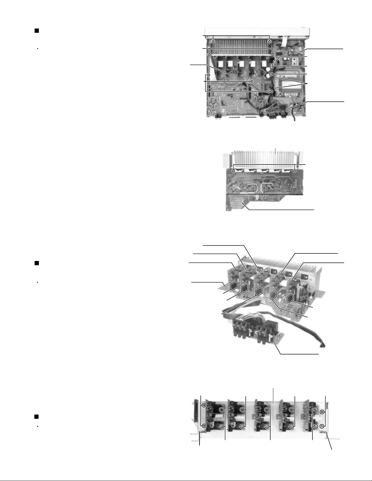
Disassembly method
Removing the top cover (See Fig.1)
1.
Remove the four screws A attaching the top cover on
both sides of the body.
2.
Remove the three screws B on the back of the body.
3.
Remove the top cover from behind in the direction of
the arrow while pulling both sides outward.
Removing the front panel assembly
(See Fig.2 and 3)
Prior to performing the following procedure, remove
the top cover.
1.
Cut off the tie band fixing the harness, if needed.
2.
Disconnect the card wire from the connector CN411
on the audio board, CN412 on the input board and
CN204 on the power supply board.
3.
Disconnect the harness form the connector CN209
on the power supply board.
Tie band
Main board
CN411
Audio board
Top cover
A
(both sides)
CN412
B
Fig.1
Front panel assembly
CC
Input board
Fig.2
CN209
D
(attaching the
headphone jack board)
CN204
Power supply
board
4.
Remove the three screws C attaching the front
panel assembly.
5.
Remove the screw D attaching the headphone jack
board.
6.
Remove the four screws E attaching the front panel
assembly on the bottom of the body. Detach the front
panel assembly toward the front.
Removing the rear panel (See Fig.4)
Prior to performing the following procedure, remove
the top cover.
1.
Remove the power cord stopper from the rear panel
by moving it in the direction of the arrow.
2.
Remove the nineteen screws F & G attaching the
each boards to the rear panel.
3.
Remove the four screws H attaching the rear panel
on the back of the body.
Rear panel
F
E
(Bottom side)
Front panel assembly
E
Fig.3
Power cord
stopper
Fig.4
F
GF
HHHH
1-3
Page 4
RX-E112RSL/RX-E111RSL
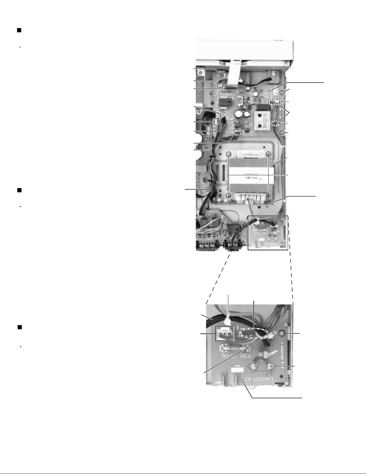
Removing the input board (See Fig.5)
Prior to performing the following procedure, remove
the top cover and rear panel.
1.
Disconnect the card wire from the connector CN412
and CN512 on the input board.
Removing the tuner board
(See Fig.5 and 6)
Prior to performing the following procedure, remove
the top cover and rear panel.
1.
Disconnect the connector CN111 and CN112 on the
tuner board and draw out the tuner board in the
direction of the arrow (see fig.5).
2.
Disconnect the connector CN513 and CN514 on the
relay board (tuner) and draw out the relay board
(tuner) in the direction of the arrow (see fig. 6).
Removing the DSP board (See Fig.5 and 6)
Prior to performing the following procedure, remove
the top cover and rear panel.
1.
Disconnect the connector CN681 on the DSP board
and draw out the DSP board in the direction of the
arrow (see fig.5).
2.
Disconnect the connector CN511 on the relay board
(DSP) and draw out the relay board (DSP) in the
direction of the arrow (see fig.6).
CN112
CN111
Tuner board
Relay board(tuner)
CN412
CN513
CN514
CN512
Fig.5
CN681
DSP board
Input board
Removing the audio board (See Fig.7)
Prior to performing the following procedure, remove
the top cover, rear panel, input board, tuner board,
DSP board and relay boards (tuner & DSP).
Remove the harness band[1] fixing the harness.
1.
Disconnect the card wire from the connector CN411
2.
on the audio board.
Disconnect the harness from the connector CN224
3.
/CN225 on the audio board.
Disconnect the harness from the connector CN515,
4.
CN516 and CN517 on the main board.
Remove the three screws I attaching the audio board.
5.
1-4
CN516
CN515
Main board
CN517
CN411
Audio board
CN511
Relay board(DSP)
Fig.6
I
Harness band[1]
CN224
/CN225
Fig.7
Page 5
RX-E112RSL/RX-E111RSL
Removing the main board with speaker
board (See Fig.8 to 10)
Prior to performing the following procedure, remove
the top cover, rear panel, input board, DSP board
and relay board (DSP).
1.
Disconnect the harness from the connector CN515,
CN516 and CN517 on the main board (see fig.7).
2.
Remove the harness band[1] (see fig.7) and harness
band[2] fixing the harness.
3.
Disconnect the harness from the connector CN707
on the power supply board .
4.
Disconnect the harness from the connector CN202
and CN226/CN227 on the main board .
5.
Remove the five screws J and two screws K
attaching the main board.
6.
Remove the two screws L attaching the heat sink to
the main board.
7.
Disconnect the connector of each amp. board.
J
K
Main
board
J
power supply
board
CN707
CN226/CN227
CN202
Harness
band[2]
Speaker board
Fig.8
Heat sink
L
Main board (reverse side)
Removing the each amp. board of Cch,
Lch, Rch, SLch and SRch (See Fig.11)
Prior to performing the following procedure, remove
the top cover and main board.
1.
Remove the two screws M attaching the Cch amp.
board and remove the Cch amp. board.
2.
Remove the two screws N attaching the Lch amp.
board and remove the Lch amp. board.
3.
Remove the two screws O attaching the Rch amp.
board and remove the Rch amp. board.
4.
Remove the two screws P attaching the SLch amp.
board and remove the SLch amp. board.
5.
Remove the two screws Q attaching the SRch amp.
board and remove the SRch amp. board.
Rch amp. board
SLch amp. board
SRch amp. board
Main board
CN704
CN703
CN702
R
P
Fig.9
Fig.10
(SLch)
Heat sink
Lch amp. board
Cch amp. board
CN701
Speaker board
N
(Lch)
CN705
R
Removing the Heat sink (See Fig.11)
Prior to performing the following procedure, remove
the top cover, main board and each amp. board.
Remove the four screws R attaching the two
1.
brackets to the heat sink and remove the two
brackets.
Bracket
Q
(SRch)
O
Fig.11
(Rch)
M
(Cch)
Bracket
1-5
Page 6
RX-E112RSL/RX-E111RSL
Removing the power supply board
(See Fig.12)
Prior to performing the following procedure, remove
the top cover.
1.
Disconnect the card wire from the connector CN204
on the power supply board.
2.
Disconnect the harness from the connector CN201,
CN209 and CN707 on the power supply board.
3.
Disconnect the harness from the connector CN226
/CN227 on the main board
4.
Remove the three screws S attaching the power
supply board and pull out the power supply board
removing the hook.
5.
Unsolder the three harness connected to the power
supply board (If necessary, cut off the band fixing the
harness on the side of the base chassis).
Removing the power transformer
(See Fig.12 and 13)
Prior to performing the following procedures, remove
the top cover.
S
CN209
CN204
Hook
CN707
CN226
/CN227
CN201
CN202
J
(fixing the
earth wire)
Power supply
board
S
PW201
PW203
Solder
PW202
S
Power
transformer
R
Power
transformer
board
1.
Cut off the tie band.
2.
Disconnect the harness from the connector CN217
on the power/fuse board.
3.
Disconnect the harness from the connector CN201
on the power supply board and CN202 on the main
board.
4.
Remove the one screw J and remove the earth wire.
5.
Remove the four screws R attaching the power
transformer.
Removing the power/fuse board
(See Fig.13)
Prior to performing the following procedure, remove
the top cover.
1.
Remove the screw G attaching the power/fuse board
to the rear panel (see fig. 4).
2.
Disconnect the harness from the connector CN217
on the power/fuse board (If necessary, cut off the
band fixing the harness on the side of the base
chassis).
Power cord
CN217
Tie band
Fig.12
Tie band
Solder
(on the reverse side)
U
Solder
Power/fuse board
Fig.13
3.
Remove the screw U attaching the power/fuse
board.
4.
Unsolder the power cord and other harness
connected to the power/fuse board.
1-6
Page 7
RX-E112RSL/RX-E111RSL
<Front panel assembly>
Removing the system control board with
power switch board (See Fig.1 to 3)
Prior to performing the following procedure, remove
the top cover and front panel assembly.
1.
Remove the two screws A attaching the power
switch board.
2.
Remove the eight screws B attaching the system
control board.
3.
Disconnect the card wire from the connector CN401,
CN402 and CN412 on the system control board.
4.
Remove the switch buttons and indicator esc., if
needed.
Removing the headphone jack board
(See Fig.1)
Prior to performing the following procedure, remove
the top cover and front panel assembly.
1.
Remove the screw C attaching the headphone jack
board to the front panel assembly.
Front panel assembly (inner side)
BBA
System control board
Power switch board (forward side)
Headphone jack board
Power switch board
C
Headphone
jack board
Fig.1
C
CN401CN412 CN402
System control board (forward side)
Fig.2
Front panel assembly (inner side)
Indicator esc.
Switch button
Fig.3
1-7
Page 8

RX-E112RSL/RX-E111RSL
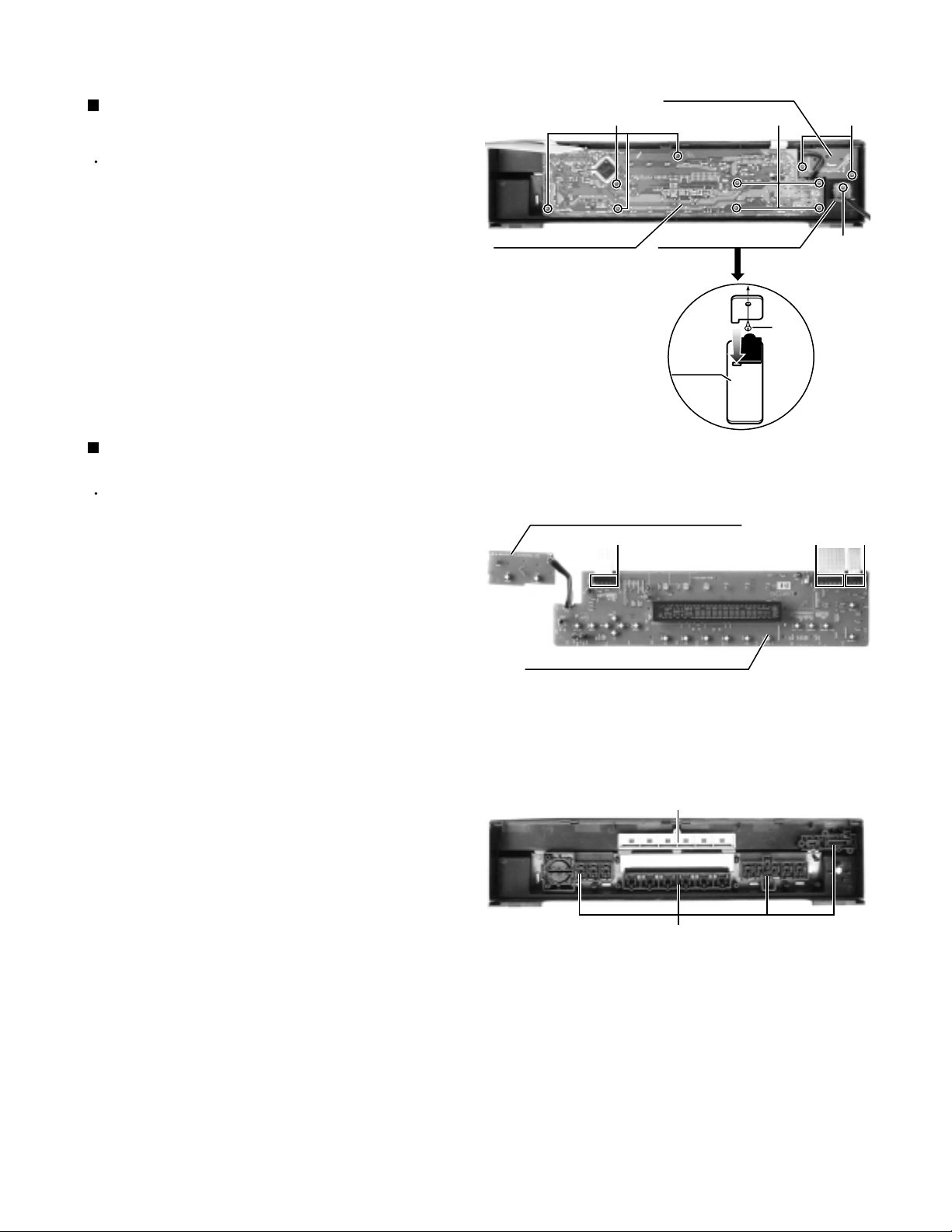
Adjustment method
Power amplifier section
Adjustment of idling current
Measurement terminal B451-B452(Lch) , B453-B454(Rch)
Adjustment volume VR301(Lch) , VR302(Rch)
Attention
This adjustment does not obtain a correct adjustment value immediately after the amplifier is
used (state that an internal temperature has risen).
Please adjust immediately after using the amplifier after turning off the power supply of the
amplifier and falling an internal temperature.
<Adjustment method>
1. Prior to turning the power ON, fully turn the adjusting resistor (VR301(Lch),VR302(Rch)) counterclockwise
direction and connect the DC voltmeter to the measuring terminal(B451-B452(Lch) , B453-B454(Rch)).
2. Set the surround mode OFF.
3. Adjust the resistor so that the measured value becomes 3.2mV immediately after turning the power ON.
4. When the idling current has been stable (about 30 minutes after the power is turned ON),
confirm that the measured value falls within 1.0mV 10mV(2.7mV).
* It is not abnormal though the idling current might not become 0mA even if it is finished to turn variable
resistance (VR301VR302) in the direction of counterclockwise.
Heat sink
Rch amp. board
B453-B454 (Rch)
Lch amp. board
B451-B452 (Lch)
VR302 (Rch)
VR301 (Lch)
1-8
Page 9

Description of major ICs
UPD784215AGC (IC671) : Unit CPU
1.Pin layout
75 ~ 51
76
~
50
~
RX-E112RSL/RX-E111RSL
100
2.Pin function
Pin No.
1~8
9
10
11
12
13
14
15
16
17
18
19
20
21
22
23
24
25~32
33
34,35
36
37,38
39
40
41
42
43
44
45,46
47
48
49
50
51,52
53
54~63
64,65
66
67
68
69,70
71
72
73~80
81
82,83
84
85
86
87
88
89
90~93
94
95~100
1 ~ 25
Symbol
VDD
X2
X1
VSS
XT2
XT1
RESET
AUTODAT A
LOCK
DIGITAL0
FORMAT
CHANNEL
ERR
RSTDET
AVDD
AVREF0
AVSS
AV REF1
RX,TX
DSPCOM
DSPSTS
DSPCLK
DSPRDY
MIDIO_IN/OUT
MICK
MICS
MILP
MIACK
DSPRST
CDTI/CDTO
CCLK
CS
XTS
PD
GND
VDD
ANA/T-TONE
LEF-MIX
S.MUTE
ASW1~4
TEST
26
I/O
O
O
O
I/O
O
O
O
O
O
I/O
O
O
O
O
O
O
O
O
O
Function
-
-
I
-
I
I
I
I
I
I
I
I
I
-
-
-
-
-
-
-
I
I
I
-
-
-
-
-
-
-
-
-
-
-
-
Non connect
Power supply terminal
Connecting the crystal oscillator for system main clock
Connecting the crystal oscillator for system main clock
Connect to GND
Connecting the crystal oscillator for system sub clock
Connecting the crystal oscillator for system sub clock
System reset signal input
Output of DSP to general-purpose port
Output of DSP to general-purpose port
Output of DSP to general-purpose port
Output of DSP to general-purpose port
Output of DSP to general-purpose port
Output of DSP to general-purpose port
Reset signal input
Power supply terminal
Connect to GND
Connect to GND
Connect to GND
Non connect
Power supply terminal
Not use
Non connect
Communication port
Status communication port
Clock input
Ready signal input
Non connect
Interface I/O terminal with microcomputer
Interface I/O terminal with microcomputer of clock signal
Interface I/O terminal with microcomputer of chip select
Interface I/O termonal with microcomputer
Interface I/O termonal with microcomputer
Non connect
Reset signal output of DSP
Non connect
Interface I/O terminal with microcomputer
Interface I/O terminal with microcomputer of clock signal
Interface I/O terminal with microcomputer of chip select
OSC Select
Non connect
Reset signal output
Connect to GND
Non connect
Power supply
Non connect
Test tone control
Control at output destination of LFE channel
Non connect
Mute of the digital out terminal is controlled
Mute of the audio signal is controlled
Non connect
Selection of digital input selector
Test terminal
Non connect
1-9
Page 10

RX-E112RSL/RX-E111RSL
AK4527B (IC601) : A/D,D/A Converter
1.Pin layout
LOOP1
LOOP0/SDA/CDTI
DIF1/SCL/CCLK
DIF0/CSN
P/S
MCLK
DZF1
AVSS
AVDD
VREFH
VCOM
SDOS
I2C
SMUTE
BICK
LRCK
SDTI1
SDTI2
SDTI3
SDTO
DAUX
DFS
4443424140393837363534
1
2
3
4
5
6
7
8
9
10
11
AK4527BVQ
T op Vie w
1213141516171819202122
NC
DZFE
TVDD
DVDD
DVSS
PDN
TSTNCADIF
CAD1
CAD0
33
32
31
30
29
28
27
26
25
24
23
DZF2/OVF
RIN+
RINLIN+
LINROUT1
LOUT1
ROUT2
LOUT2
ROUT3
LOUT3
2. Pin function (1/2)
No.
1
Pin name
SDOS
I/O
I
SDTO Source Select Pin (Note 1)
Function
"L" : Internal ADC output, "H" : DAUX input
2
3
I2C
SMUTE
I
Control Mode Select Pin
"L" : 3-wire Serial, "H" : I
I
Soft Mute Pin (Note 1)
2
C Bus
When this pin goes to "H", soft mute cycle is initialized.
When returning to "L", the output mute releases.
4
5
6
7
8
9
10
11
BICK
LRCK
SDTI1
SDTI2
SDTI3
SDTO
DAUX
DFS
I
Audio Serial Data Clock Pin
I/O
Input Channel Clock Pin
I
DAC1 Audio Serial Data Input Pin
I
DAC2 Audio Serial Data Input Pin
I
DAC3 Audio Serial Data Input Pin
O
Audio Serial Data Output Pin
I
Sub Audio Serial Data Input Pin
I
Double Speed Sampling Mode Pin (Note 1)
"L" : Normal Speed, "H" : Double Speed
12
NC
-
No Connect
No internal bonding.
13
DZEF
I
Zero Input Detect Enable Pin
"L" : mode 7 (disable) at parallel mode,
zero detect mode is selectable by DZFM2-0 bits at serial mode.
"H" : mode 0 (DZF is AND of all six channels)
14
15
16
17
TVDD
DVDD
DVSS
PDN
-
Output Buffer Power supply Pin, 2.7V~5.5V
-
Digital Power Supply Pin, 4.5V~5.5V
-
De-emphasis Pin, 0V
I
Power-Down & Reset Pin
When "L", the AK4527B is powered-do wn and the control registers are reset to def ault
state. If the state of P/S or CAD0-1 changes, then the AK4527B m ust be reset b y PDN.
18
TST
I
Test Pin
This pin should be connected to DVSS.
1-10
Page 11

RX-E112RSL/RX-E111RSL
2. Pin function (2/2)
No.
19
20
21
22
23
24
25
26
27
28
29
30
31
32
33
34
35
36
37
38
39
40
41
42
43
44
Pin name
NC
ADIF
CAD1
CAD0
LOUT3
ROUT3
LOUT2
ROUT2
LOUT1
ROUT1
LINLIN+
RINRIN+
DZF2
OVF
VCOM
VREFH
AVDD
AVSS
DZF1
MCLK
P/S
DIF0
CSN
DIF1
SCL/CCLK
LOOP0
SAD/CDTI
LOOP1
I/O
No Connect
No internal bonding.
Analog Input Format Select Pin
I
"H" : Full-differential input, "L" : Single-ended input
Chip Address 1 Pin
I
Chip Address 0 Pin
I
DAC3 Lch Analog Output Pin
O
DAC3 Rch Analog Output Pin
O
DAC2 Lch Analog Output Pin
O
DAC2 Rch Analog Output Pin
O
DAC1 Lch Analog Output Pin
O
DAC1 Rch Analog Output Pin
O
Lch Analog Negative Input Pin
I
Lch Analog Positive Input Pin
I
Rch Analog Negative Input Pin
I
Rch Analog Positive Input Pin
I
Zero Input Detect 2 Pin (Note 2)
O
When the input data of the group 1 follow total 8192LRCK cycles with "0" input data,
this pin goes to "H".
Analog Input Overflow Detect Pin (Note 3)
O
This pin goes to "H" if the analog input of Lch or Rch is overflows.
Common Voltage Output Pin,AVDD/2
O
Large external capacitor around 2.2uF is used to reduce power-supply noise.
Positive Voltage Reference Input Pin,AVDD
I
Analog Power Supply Pin,4.5V~5.5V
Analog Ground Pin,0V
Zero Input Detect 1 Pin (Note 2)
O
When the input data of the group 1 follow total 8192 LRCK cycles with "0" input data,
this pin goes to "H".
Master Clock Input Pin
I
Parallel / Serial Select Pin
I
"L" : Serial control mode, "H" : Parallel control mode
Audio Data Interface Format 0 Pin in parallel mode
I
Chip select pin in 3-wire serial control mode
I
This pin should be connected to DVDD at I2C bus control mode
Audio Data Interface Format 1 Pin in parallel mode
I
Control Data Clock Pin in serial control mode
I
I2C = "L" : CCLK(3-wire Serial), I2C = "H" : SCL(I2CBus)
Loopback Mode 0 Pin in parallel control mode
I
Enables digital loop-back from ADC to 3 DACs.
Control Data Input Pin in serial control mode
I/O
I2C = "L" : CDTI(3-wire Serial), I2C = "H" : SDA(I2CBus)
Loopback Mode 1 Pin (Note 1)
I
Enable all 3 DAC channels to be input from SDTII.
Function
Notes : 1. SDOS, SMUTE, DFS, and LOOP1 pins are ORed with register data if P/S = "L".
2. The group 1 and 2 can be selected by DZFM2-0 bit if P/S = "L" and DZFME = "L".
3. This pin becomes OVF pin if OVFE bit is set to "1" at serial control mode.
4. All input pins should not be left floating.
1-11
Page 12

RX-E112RSL/RX-E111RSL
M61501FP (IC501) : Analog sound processor
1. Block diagram
40 39 38 37 36 35 34 33 32 31 30 29 28 27 26 25
41
42
43
44
45
46
47
48
49
50
51
52
53
54
55
56
57
58
59
60
61
62
63
64
0/6/10dB
A
SW2
A
B
B
A
B
M
M
0/6/10dB
M
Lch Vol
BYPASS
A
TONE
B
B
A
SW1
ATT
0/-6dB
SLch Vol
10/2dB
Cch Vol
Bus boost
MCU I/F
0/6/10dB
+
SWch Vol
Bus boost
L+R+C
SRch Vol
0/6/10dB
Rch Vol
BYPASS
TONE
0/6/10dB
SW1
M
A
B
B
A
ATT
0/-6dB
B
A
B
M
0/6/10dB
B
M
SW2
10/2dB
24
23
22
21
20
19
A
18
17
16
15
14
13
A
12
11
10
9
8
7
6
5
4
3
2
1
65 66 67 68 69 70 71 72 73 74 75 76 77 78 79 80
2. Pin function (1/2)
Pin No.
1
2
3
4
5
6
7
8
9
10
11
12
13
14
15
16
17
18
19
20
21
Symbol
NC
ING1
RECOUT1B
RECOUT1A
SELOUT1
TINA1
TINB1
TCC
TCB1
TCA1
TONEOUT1
SWOUT
AGND
RchAIN
RchBIN
RchOUT
RchBBO
RchBBI
AGND
SRchAIN
SRchBIN
I/O
-
I
O
O
O
I
I
I
I
I
O
O
-
I
I
O
O
I
-
I
I
Function
No connect
G signal input of right side input selector
B through signal output of right side
A through signal output of right side
Signal output after 0/-6dB of right side
Tone A signal input of right side
Tone B signal input of right side
Tone C control of right side
Tone B control of right side
Tone A control of right side
Tone signal output of right side
L+R+C signal output
Analog ground for Rch
A select signal input of Rch
B select signal input of Rch
Signal output of Rch
Bus boost control output of Rch
Bus boost control input of Rch
Analog ground for SRch
A signal input of SRch
B signal input of SRch
1-12
Page 13

RX-E112RSL/RX-E111RSL
2. Pin function (2/2)
Pin No.
22
23
24
25
26
27
28
29
30
31
32
33
34
35
36
37
38
39
40
41
42
43
44
45
46
47
48
49
50
51
52
53
54
55
56
57
58
59
60
61
62
63
64
65
66
67
68
69
70
71
72
73
74
75
76
77
78
79
80
Symbol
SRchOUT
AGND
NC
NC
SWchAIN
SWchBIN
SWchOUT
AVSS
DVDD
CLOCK
DATA
LATCH
DGND
AGND
AGND
CchOUT
CchBIN
CchAIN
NC
NC
AGND
SLchOUT
SLchBIN
SLchAIN
AGND
LchBBI
LchBBO
LchOUT
LchBIN
LchAIN
AGND
NC
TONEOUT2
TCA2
TCB2
TCC2
TINB2
TINA2
SELOUT2
RECOUT2A
RECOUT2B
ING2
NC
NC
INF2
INE2
IND2
INC2
INB2
INA2
AVDD
AVDD
INA1
INB1
INC1
IND1
INE1
ING1
NC
I/O
O
-
-
-
O
-
-
-
-
-
O
-
-
-
O
-
O
O
-
-
O
O
O
O
-
-
-
-
-
Function
Signal output of SRch
Analog ground for SWch
No connect
No connect
I
I
I
I
I
I
I
I
I
I
I
I
I
I
I
I
I
I
I
I
I
I
I
I
I
I
I
I
I
I
A select signal input of SWch
B select signal input of SWch
Signal output of SWch
Analog power supply
Digital power supply
Digital clock input
Digital data input
Digital latch input
Digital ground
Analog ground
Analog ground
Signal output of Cch
B select signal input of Cch
A select signal input of Cch
No connect
No connect
Analog ground for Cch
Signal output of SLch
B select signal input of SLch
A select signal input of SLch
Analog ground for SLch
Bus boost control input of Lch
bus boost control output of Lch
Signal output of Lch
B select signal input of Lch
A select signal input of Lch
Analog ground for Lch
No connect
Tone signal output of left side
Tone A control of left side
Tone B control of left side
Tone C control of left side
Tone B signal input of left side
Tone A signal input of left side
Signal output after 0/-6dB of left side
A through signal output of left side
B through signal output of left side
G signal input of left side input selector
No connector
No connector
F signal input of left side input selector
E signal input of left side input selector
D signal input of left side input selector
C signal input of left side input selector
B signal input of left side input selector
A signal input of left side input selector
Analog power supply
Analog power supply
A signal input of right side input selector
B signal input of right side input selector
C signal input of right side input selector
D signal input of right side input selector
E signal input of right side input selector
F signal input of right side input selector
No connect
1-13
Page 14

RX-E112RSL/RX-E111RSL
LA1838(IC102) : FM AM IF amp. & detector, FM MPX decoder
1. Block diagram
30
ALC
BUFF
FM
S-METER
FM IF
1
2. Pin function
Pin
Symbol
No.
FM IN
1
AM MIX
2
3
FM IF
AM IF
4
GND
5
6
TUNED
STEREO
7
8
VCC
9
FM DET
10
AM SD
FM VSM
11
AM VSM
12
13
MUTE
14
FM/AM
MONO/ST O
15
29
28
AM
OSC
SD
COMP
S-CLRVE
PM
DET
2
I/O
I
This is an input terminal of FM IF
REG
AM
MIX
AM/FM
IF-BUFF
3
27
FM
RF.AMP
AM IF
4
26
AGC
AM
S-METER
GND
Function
DET
5
signal.
This is an out put terminal for AM
O
mixer.
I
Bypass of FM IF
Input of AM IF Signal.
I
I
This is the device ground terminal.
When the set is tuning, this terminal
O
becomes "L".
O
Stereo indicator output. Stereo "L",
Mono: "H"
III
This is the power supply terminal.
I
FM detect transformer.
I
This is a terminal of AM ceramic filter.
O
Adjust FM SD sensitivity.
O
Adjust AM SD sensitivity.
I/O
When the signal of IF REQ of IC121(
LC72131) appear, the signal of FM/AM
IF output. //Muting control input.
Change over the FM/AM input.
I
"H" :FM, "L" : AM
Stereo : "H", Mono: "L"
25
TUNING
DRIVE
6
24
STEREO
DRIVE
7
22
23
P-DET
VCC
89
Pin
Symbol
No.
16
L OUT
17
R OUT
18
19
20
21
22
23
24
25
26
27
28
29
30
L IN
R IN
RO
LO
IF IN
FM OUT
AM DET
AM AGC
AFC
AM RF
REG
AM OSC
OSC BUFFER
21
DECODER
ANIT-BIRDIE
VCO
384KHz
10
20
STEREO
5N
SW
FF
38k
11
I/O
O
Left channel signal output.
O
Right channel signal output.
Input terminal of the left channel post
I
18
19
MUTE
FF
/
19k
2
12 13
FF
19k
/
LS
Function
17 16
PILOT
DET
14
AMP.
Input terminal of the right channel
I
post AMP.
Mpx Right channel signal output.
O
O
Mpx Left channel signal output.
I
Mpx input terminal
FM detection output.
O
AM detection output.
O
This is an AGC voltage input terminal
I
for AM
I
This is an output terminal of voltage
for FM-AFC.
AM RF signal input.
I
Register value between pin 26 and pin28
O
desides the frequency width of the
input signal.
I
This is a terminal of AM Local
oscillation circuit.
AM Local oscillation Signal output.
O
15
1-14
Page 15

LC72136N (IC121) : PLL frequency synthesizer
1. Pin layout
FM/ST/VCO
2. Block diagram
XT
FM/AM
CE
DI
CLOCK
DO
AM/FM
SDIN
1
2
3
4
5
6
7
8
9
10
11
22
21
20
19
18
17
16
15
14
13
12
XT
GND
LPFOUT
LPFIN
PD
VCC
FMIN
AMIN
IFCONT
IFIN
RX-E112RSL/RX-E111RSL
1
22
16
15
3
4
5
6
17
21
3. Pin function
Pin
Symbol
No.
1
2
3
4
5
6
7
8
9
10
11
XT
FM/AM
CE
DI
CLOCK
DO
FM/ST/VCO
AM/FM
LW
MW
SDIN
Reference
Driver
Swallow Counter
1/2
2B
C
I/F
Power
on
Reset
Function
I/O
X'tal oscillator connect (75kHz)
I
LOW:FM mode
O
When data output/input for 4pin(input) and
I
Swallow Counter
1/16,1/17 4bit
1/16,1/17 4bit
12bit
Programmable
DriverS
Data Shift Register & Latch
7821113
6pin(output): H
Input for receive the serial data from
I
controller
Sync signal input use
I
Data output for Controller
O
Output port
"Low": MW mode
O
Open state after the power on reset
O
Input/output port
I/O
Input/output port
I/O
Data input/output
I/O
Phase
Detector
Charge Pump
Unlock
Detector
Universal
Counter
Pin
No.
12
IFCONT
13
14
15
16
17
18
19
LPFOUT
20
21
22
Symbol
IFIN
AMIN
FMIN
VCC
PD
LPFIN
GND
XT
18
19
20
12
I/O
Function
IF counter signal input
I
IF signal output
O
Not use
-
AM Local OSC signal output
I
FM Local OSC signal input
I
Power suplly(VDD=4.5-5.5V)
When power ON:Reset circuit move
PLL charge pump output(H: Local OSC
O
frequency Height than Reference frequency.
L: Low Agreement: Height impedance)
Input for active lowpassfilter of PLL
I
Output for active lowpassfilter of PLL
O
Connected to GND
X'tal oscillator(75KHz)
I
1-15
Page 16

RX-E112RSL/RX-E111RSL
NJU3713 (IC402) : L.E.D. driver
1.Pin layout
P5
2.Block diagram
P6
P7
P8
Vss
P9
P10
p11
P12
1
2
3
4
5
6
7
8
9
18
17
16
15
14
13
12
11
10
VDD
P4
P3
P2
P1
CLR
STB
CLK
DATA
DATA
CLK
STB
CLR
3.Pin function
Shift
resistor
Control Circuit
Latch
circuit
P1
P2
P3
P4
P5
P11
P12
1-16
PIN No.
1~4
5
6~9
10
11
12
13
14
15
16~17
18
I/O
O
O
O
I
I
I
O
O
O
-
Symbol
P5, P6, P7, P8
Vss
P9, P10, P11, P12
DA TA
CLK
STB
CLR
P1
P2
P3, p4,
DD
V
Function
Parallel conversion data output terminal.
Connect to GND.
Parallel conversion data output terminal.
Serial data input terminal.
Clock signal input terminal.
Strobe signal input terminal.
Clear signal input terminal.
Parallel conversion data output terminal.
Parallel conversion data output terminal.
Parallel conversion data output terminal.
Power supply terminal.
Page 17

SAA6588 (IC191) : RDS detector
RX-E112RSL/RX-E111RSL
1. Pin layout
MRO
NC
GND
OSCO
OSCI
VSSD
VDDD
DAVN
SDA
SCL
1
2
3
4
5
6
7
8
9
10
20
19
18
17
16
15
14
13
12
11
NC
CIN
SCOUT
Vref
MPX
VSSA
VDDA
NC
GND
NC
2. Pin function
Pin
No.
1
2
3
4
5
6
7
8
9
10
11
12
13
14
15
16
17
18
19
20
MRO
GND
OSCO
OSCI
VSSD
VDDD
DAVN
SDA
SCL
GND
VDDA
VSSA
MPX
Vref
SCOUT
CIN
NC
NC
NC
NC
FunctionI/OSymbol
Multi-path rectifier output
O
Non connect
Test control input pin
I
Oscillator output
O
Oscillator input
I
Digital ground (0V)
Digital power supply (5V)
Data available output (active LOW)
O
IC-bus serial data I/O
I/O
IC-bus serial clock input
I
Non connect
Connect to ground
Non connect
Analog power supply (5V)
Connect to ground
Multiplex input signal
I
Reference voltage output
O
Band-pass filter output
O
Comparator output
O
Level input
I
3. Block diagram
16
MPX
13
AFIN
LVIN
20
14
VDDA
8th ORDER
BAND-PASS
DETECTOR
POWER
SUPPLY
AND RESET
VSSA
SCOUT
57 kHz
PAUSE
15
18
17
Vref
19
CLOCK
COMPARATOR
MULTI-PATH
DETECTOR
TEST
CONTROL
3
TCON
RDS/RDBS
DEMODULATOR
SIGNAL QUALITY
DETECTOR
OSCILLATOR
AND CLOCK
1
MRO
OSCI OSCO
VDDDCIN
7
DAVN
12
MAD
11
10
8
2
9
PSWN
MPTH
SDA
SCL
RDS/RDBS
DECODER
INTERFACE
REGISTER
IC-BUS SLAVE
TRANSCEIVER
5
4
6
VSSD
1-17
Page 18

RX-E112RSL/RX-E111RSL
L
TC9446F-025 (IC631) : Audio digital processor
1. Block diagram
Program
ROM
4k word x3
RAM
128 word
Program
Instruction
control
IRQ
Interrupt
RX
2
4
MCU interface
Audio
Interface
DIR
Timer
SDIn
SDOn
RCK/BCK
LOCK
RST
MIMD
MICS
MILP
MIDIO
MICK
MIACK
40 bit
Instruction
Detector
1 bus
X bus
Y bus
XRAM
4k word
YRAM
4k word
Register
X0, X1, X2
Y0, Y2, Y3
MX
A1
CROM
4k word
MY
MAC ALU
Round/Limiter Round/Limiter
ERAM
4k word
MZ
A0 A2 A3
AX
Address Operater
X pointer
register
AY
x2
Y pointer
register
C pointer
register
Timing
DLL
Bus switch
External SRAM
interface
General output
port
Flag
DIT
17
3
8
8
4
SCKO
SCKI
DLON
LPFO
CE, OE, WR
ADn
IOn
POn
FIn
TXO
2. Pin function
Pin No.
8~11
12
13
14
15
16~19
20
21
22, 23
24
25
26
27, 28
29
30
31
32,33
34
35
36
37
38
39
40
1-18
1
2
3
4
5
6
7
Symbol
RST
MIMD
MICS
MILP
MIDIO
MICK
MIACK
FI0~3
IRQ
VSS
LRCKA
BCKA
SDO0~3
LRCKB
BCKB
SDI0, 1
VDD
LRCKOA
BCKOA
TEST0,1
LRCKOB
BCKOB
TXO
TEST2,3
RX
VSS
TSTSUB0
FCONT
TSTSUB1
TSTSUB2
PDO
I/O
Function
I
Reset signal input terminal
(L:reset H:nomal operation)
I
Mode select input for MCU interface
(L:serial H:IC bus)
I
Chip select input for MCU interface
I
Latch pulse input for MCU interface
I/O
Data I/O for MCU interface
I
Clock input for MCU interface
O
Acknowledge output for MCU interface
I
Flag input 0~3
I
Interrupt input
-
Digital ground
I
LR clock input-A for audio interface
I
Bit clock input-A for audio interface
O
Data output-0~3 for audio interface
I
LR clock input-B for audio interface
I
Bit clock input-B for audio interface
I
Data input-0, 1 for audio interface
-
Digital power supply
O
LR clock output-A for audio interface
O
Bit clock output-A for audio interface
I
Test input-0, 1 (L:test H:nomal operation)
O
LR clock output-B for audio interface
O
Bit clock output-B for audio interface
O
SPDIF output
I
Test input-2, 3 (L:test H:nomal operation)
I
SPDIF input
-
Digital ground
I
Test sub input-0 (L:test H:nomal operation)
O
Frequency control output for VCO circuit
I
Test sub input-1, 2
(L:test H:nomal operation)
O
Phase detect signal output
Pin No.
41
42
43
44
45
46
47
48
49
50
51
52
53
54~61
62
63~70
71
72~80
81
82~89
90
91
92
93
94
95
96
97
98, 99
100
Symbol
VDDA
PLON
AMPI
AMPO
CKI
VSSA
CKO
LOCK
VSS
WR
OE
CE
VDD
IO7~0
VSS
AD0~7
VDD
AD8~16
VSS
PO0~7
VDDDL
LPFO
DLON
DLCKS
SCKO
VSSDL
SCKI
VSSX
XO,XI
VDDX
I/O
Function
-
Analog power supply
I
Clock selection input
(L:external clock H:VCO clock)
I
AMP.input for LPF
O
AMP.output for LPF
I
External clock input
-
Analog ground
O
DIR clock output
O
VCO lock output
-
Gigtal ground
O
Writing signal output for extrenal SRAM
O
Enable signal output for external SRAM
O
Chip enable signal output for external SRAM
-
Digital power supply
I/O
Data I/O-7~0 for external SRAM
-
Digital ground
O
Address output-0~7 for external SRAM
-
Digital power supply
O
Address output-8~16 for external SRAM
-
Digital ground
O
General output port-0~7
-
Power supply for DLL circuit
O
LPF output for DLL circuit
I
*
O
ASP clock output
-
Ground for DLL circuit
I
External system clock input
-
Ground for crysoal oscillator
I/O
Crystal oscillator I/O
-
Digital power supply
*
DLCKS pin
DLON pin
L
L
H
H
DLL clock setting
L
SCKI input (DLL circuit OFF)
H
Four times XI clock
L
Three times XI clock
H
Six times XI clock
Page 19

BA033LBSG (IC683) : Standard voltage power supply
1. Block diagram
RX-E112RSL/RX-E111RSL
Vcc 1
CLT 3
GND 2
Standard voltage
Current restriction
circuit
Temperature
protection circuit
5 OUT
4 C
BA15218F (IC503, IC609, IC610, IC650, IC651, IC661, IC690, IC691) : OP amp.
1. Block diagram
EE
1OUT1
2-IN1
1
3+IN1
+
2
4
8
V
CC
7
OUT2
6
5V
-IN2
+IN2
-
+
BA7625 (IC514) : Video selector
1. Block diagram 2. Truth table
MONITOR OUT
GND
IN5
GND
IN4
CTL E
IN3
CTL D
1
2
3
4
5
6
7
8
logic
logic
16
15
14
13
12
11
10
11
IN1
CTL A
VOUT 1
CC
V
IN2
CTL B
VOUT 2
CTL C
A B E MONITOR OUT
LL
HL
LH
H H L IN4
HHH
*
*
*
C D E VOUT1
LL
HL
LH
H H L IN4
HHH
*
*
*
C D E VOUT2
LL
HL
LH
H H L IN4
H H H IN5
*
*
*
IN1
IN2
IN3
IN5
-IN2
IN3
IN5
IN1
-IN3
1-19
Page 20

RX-E112RSL/RX-E111RSL
TC74HC08AF (IC611) : AND gate
1. Pin layout
1A
1B
1Y
2A
2B
2Y
GND
1
2
3
4
5
6
7
14
13
12
11
10
9
8
Vcc
4B
4A
4Y
3B
3A
3Y
TC74HC4072AF (IC612) : OR gate
1. Pin layout
1Y
1A
1B
1C
1D
NC
GND
1
2
3
4
5
6
7
14
13
12
11
10
9
8
Vcc
2Y
2D
2C
2B
2A
NC
2. Truth table
A
L
L
H
H
2. Truth table
A
B
H
X
X
H
X
X
X
X
L
L
X : Don't care
B
L
H
L
H
Y
L
L
L
H
C
D
Y
X
X
H
X
X
H
H
X
H
X
H
H
L
L
L
TC74HC4053A (IC515) : Multiplexer
1. Pin layout
1Y
1-20
0Y
1Z
Z-COM
0Z
INH
V
GND
EE
1
2
3
4
5
6
7
8
16
15
14
13
12
11
10
9
Vcc
Y-COM
X-COM
1X
0X
A
B
C
2. Truth table
CONTROL INPUTS
INHIBIT
L
L
L
L
L
L
L
L
H
X: Don't Care.
C
L
L
L
L
H
H
H
H
X
B
H
H
H
H
"ON" CHANNEL
A
L
L
L
H
L
H
L
L
L
H
L
H
X
X
0X, 0Y, 0Z
1X, 0Y, 0Z
0X, 1Y, 0Z
1X, 1Y, 0Z
0X, 0Y, 1Z
1X, 0Y, 1Z
0X, 1Y, 1Z
1X, 1Y, 1Z
NONE
Page 21

NJM2246M (IC511, IC512, IC513) : Video switch
1. Block diaglam
RX-E112RSL/RX-E111RSL
GND Vout V+ Vin3
8 7 6 5
6dB
AMP.
BIAS
1 2 3 4
Vin1 CTL1 Vin2 CTL2
INPUT CONTROL SIGNAL- OUTPUT SIGNAL
CTL1
L
H
L/ H
CTL2
L
L
H
OUTPUT SIGNAL
Vin1
Vin2
Vin3
TC74HCU04AF (IC621) : Inverter
1. Pin layout
1Y
2A
2Y
3A
3Y
11A
2
3
4
5
6
7
14
13
12
11
10
9
8GND
VCC
6A
6Y
5A
5Y
4A
4Y
TC7SET32FU (IC672) : 2 input or gate
1
IN B
A
L
H
Y
H
L
54VCC
IN A
GND
2
3
OUT Y
1-21
Page 22

RX-E112RSL/RX-E111RSL
W24L010AJ-12 (IC641) : CMOS SRAM
32
NC
A16
A14
A12
A7
A6
A5
A4
A3
A2
A1
A0
I/O1
I/O2
I/O3
Vss
1
2
3
4
5
6
7
8
9
10
11
12
13
14
15
16
31
30
29
28
27
26
25
24
23
22
21
20
19
18
17
VDD
A15
CS2
WE
A13
A8
A9
A11
OE
A10
CS2
I/O8
I/O7
I/O6
I/O5
I/O4
2. Block diagram1. Pin layout
A16
A14
A12
A4
A3
A2
A7
A6
A5
A9
I/O 1
I/O8
WE
R
O
W
D
E
C
O
D
E
R
DATA
CNTRL.
CLK
GEN.
PRECHARGE CKT.CLK GEN.
CORE CELL ARRAY
7024 ROWS
728x8 COLUMN5
I/O CKT
COLUMN DECODER
A15 A13 A8 A1 A0 A11 A10
CS1
CS2
OE
1-22
Page 23

< MEMO >
RX-E112RSL/RX-E111RSL
1-23
Page 24

RX-E112RSL/RX-E111RSL
VICTOR COMPANY OF JAPAN, LIMITED
AUDIO & COMMUNICATION BUSINESS DIVISION
PERSONAL & MOBILE NETWORK BUSINESS UNIT. 10-1,1chome,Ohwatari-machi,Maebashi-city,371-8543,Japan
(No.21085)
200204
 Loading...