

Page 1
AUDIO/VIDEO CONTROL RECEIVER
RX-8022PSL
A/V CONTROL RECEIVER
CATV/DBS VCR1 TV AUDIO
DVD
DVD MULTI
CD
CDR
TV/DBS VIDEO PHONO
TAPE/MD
VCR1 VCR 2
SURR/DSP
ANALOG/DIGITAL
DSP
SURROUND
OFF
ANALOG
BASS
DIRECT
BOOST∗FRONT•L
231
MENU
SOUND
CENTER∗SUBWFR
TEST
∗
564
ENTER
SURR•L∗SURR•R
DIMMER
∗
7/P
89
SBACK•L∗SBACK•R
DIGITAL EQ
MUTING
∗
∗
0
10
RETURN FM MODE 100
CATV/DBS
CONTROL
+−+−+
CH/
LEVEL
TV VOL
∗
TV/VIDEO
TEXT
PLAY
MENU
DISPLAY
REC
/REW
PAUSE
PAUSE
SET
DOWN – TUNING – UP
SLEEP
STOP
RM-SRX8020J
REMOTE CONTROL
FM/AM
FRONT•R
∗
VOLUME
FF/
CONTROL
USB
INPUT
FM/AM TUNING FM/AM PRESET FM MODE
STANDBY
+10
+
−
EXIT
STANDBY/ON
SPEAKERS ON/OFF
SUBWOOFER OUT ON/OFF
PHONES
1
SURROUND
2
USB AUDIO
PUSH OPEN
DSP
S-VIDEO VIDEO
MEMORY
SURROUND/DSP
OFF
VIDEO
ANALOG/DIGITAL
L—AUDIO—R
RX-8022P
AUDIO/VIDEO CONTROL RECEIVER
MASTER VOLUME
TV SOUND/DBSVIDEOVCR 2VCR 1DVDDVD MULTI
DIGITAL
INPUT
INPUT ATT
SOUCE NAME
SOURCE NAME
LEVEL
EQ
ADJUST
EFFECT SETTING
FM/AMUSB AUDIOTAPE/MDCDRCDPHONO
CONTROL
DOWN UP
ANALOG DIRECT
BASS BOOST
INSTRUCTIONS
For Customer Use:
Enter below the Model No. and Serial
No. which are located either on the rear,
bottom or side of the cabinet. Retain this
information for future reference.
Model No.
Serial No.
LVT0870-006A
[A]
Page 2

Warnings, Cautions and Others
Caution ––
Disconnect the mains plug to shut the power off completely.
The
line. The power can be remote controlled.
CAUTION
To reduce the risk of electrical shocks, fire, etc.:
CAUTION
• Do not block the ventilation openings or holes.
• Do not place any naked flame sources, such as lighted
• When discarding batteries, environmental problems must
• Do not expose this apparatus to rain, moisture, dripping
switch in any position does not disconnect the mains
1. Do not remove screws, covers or cabinet.
2. Do not expose this appliance to rain or moisture.
(If the ventilation openings or holes are blocked by a
newspaper or cloth, etc., the heat may not be able to get
out.)
candles, on the apparatus.
be considered and local rules or laws governing the
disposal of these batteries must be followed strictly.
or splashing and that no objects filled with liquids such as
vases, shall be placed on the apparatus.
switch!
G-1
Page 3
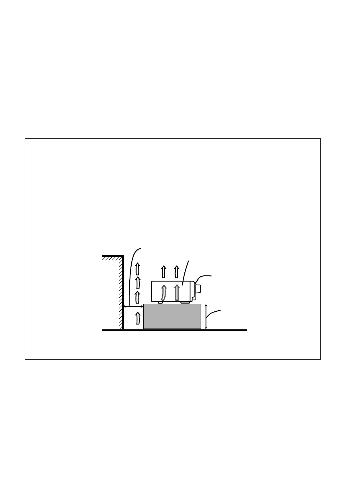
Caution: Proper Ventilation
To avoid risk of electric shock and fire and to protect from
damage.
Locate the apparatus as follows:
Front: No obstructions open spacing.
Sides: No obstructions in 10 cm from the sides.
Top: No obstructions in 10 cm from the top.
Back: No obstructions in 15 cm from the back
Bottom: No obstructions, place on the level surface.
In addition, maintain the best possible air circulation as illustrated.
Wall or obstructions
Spacing 15 cm or more
RX-8022PSL
Front
Stand height 15 cm or more
Floor
G-2
Page 4

Table of Contents
Introduction ................................................ 2
Features ...................................................................................... 2
Precautions ................................................................................. 2
Parts Identification ...................................... 3
Getting Started ........................................... 5
Setting Sound ........................................... 30
Attenuating the Input Signal .................................................... 30
Turning Analog Direct On and Off .......................................... 30
Reinforcing the Bass ................................................................ 31
Activating the Subwoofer Sound ............................................. 31
Before Installation ...................................................................... 5
Checking the Supplied Accessories ........................................... 5
Setting the Voltage Selector........................................................ 5
Connecting the FM and AM Antennas ....................................... 5
Connecting the Speakers ............................................................ 6
Connecting Audio/Video Components ....................................... 8
7 Analog Connections ............................................................... 8
7 Digital Connections .............................................................. 13
7 USB Connection ................................................................... 14
Connecting the Power Cord ..................................................... 15
Putting Batteries in the Remote Control .................................. 15
Basic Operations ....................................... 16
Turning On the Power .............................................................. 16
Selecting the Source to Play ..................................................... 16
Adjusting the Volume ............................................................... 18
Selecting the Front Speakers .................................................... 18
Listening Only with Headphones ............................................. 18
Selecting the Analog or Digital Input Mode ............................ 19
Muting the Sound ..................................................................... 20
Changing the Display Brightness ............................................. 20
Using the Sleep Timer .............................................................. 20
Basic Settings ........................................... 21
Basic Procedure ........................................................................ 21
1 Setting the Speakers ........................................................... 22
2 Selecting Channel Numbers to Reproduce
Multi-channel Digital Software ................................... 23
3 Setting the Speaker Distance ............................................. 23
4 Setting the Bass Sounds ..................................................... 24
5 Setting the Dynamic Range ............................................... 24
6 Setting the Digital Input (DIGITAL IN) Terminals ........... 25
7 Setting the Component Video Input ................................... 25
8 Memorizing the Volume Level for Each Source ................ 26
9 Showing the Text Information on the Display ................... 26
Using Surround Modes and DSP Modes ........
7 Surround Modes ................................................................... 32
Reproducing Theater Ambience ................................................ 32
Introducing the Surround Modes ............................................. 32
7 DSP Modes ........................................................................... 34
Available Surround and DSP Modes According to
the Speaker Layouts ........................................................... 35
Activating the Surround Modes ............................................... 36
Activating the DSP Modes ....................................................... 36
32
Using the DVD MULTI Playback Mode .......... 37
Activating the DVD MULTI Playback Mode .......................... 37
Adjusting Sound ........................................ 38
Basic Procedure ........................................................................ 38
Adjusting the Equalization Patterns—DIGITAL EQ ............... 39
Adjusting the Speaker Output Levels—LEVEL ADJUST ...... 40
Adjusting the Sound Parameters for the Surround and
DSP Modes—EFFECT ADJUST ...................................... 42
COMPU LINK Remote Control System ......... 43
TEXT COMPU LINK Remote Control System ... 44
7 Showing the Disc Information on the TV Screen................. 45
7 Searching for a Disc (Only for the CD player) .................... 46
7 Entering the Disc Information .............................................. 47
AV COMPU LINK Remote Control System .... 49
Operating JVC’s Audio/Video Components ... 51
Operating Audio Components .................................................. 51
Operating Video Components .................................................. 53
Operating Other Manufacturers’ Video
Equipment ............................................ 54
Receiving Radio Broadcasts ........................ 27
Tuning into Stations Manually ................................................. 27
Using Preset Tuning ................................................................. 27
Selecting the FM Reception Mode ........................................... 28
Operating the Tuner Using the On-Screen Display.................. 29
1
Troubleshooting ......................................... 57
Specifications ............................................ 59
Page 5

Introduction
We would like to thank you for purchasing one of our JVC products.
Before operating this unit, read this manual carefully and thoroughly to obtain the best possible performance
from your unit, and retain this manual for future reference.
Features
Dolby Digital EX*
Dolby Digital EX is newly introduced surround encoding format
as an extension of multi-channel Dolby Digital, designed to add
an extra surround channel to Dolby Digital 5.1-channel. By using
a matrix encoding/decoding method, additional “surround back”
channel signal is encoded (and decoded) in both the left and right
surround channel signals.
DTS-ES Extended Surround (DTS-ES)**
DTS-ES is another new format developed by Digital Theater
Systems, Inc., adding a surround back channel on the basis of
DTS Digital Surround.
Dolby Pro Logic II*
Dolby Pro Logic II converts all 2-channel stereo software,
especially Dolby Surround encoded software, into 5-channel
(plus subwoofer) signals. It reproduces realistic Surround sounds
approaching to Dolby Digital 5.1-channel. Dolby Pro Logic II has
two modes to reproduce—Movie mode and Music mode.
Neo:6**
Neo:6 can reproduce realistic Surround fields by converting
2-channel stereo software into 6-channel (plus subwoofer) signals.
Neo:6 has two modes to reproduce—Neo:6 Cinema and Neo:6
Music.
DAP (Digital Acoustic Processor)
Sound field simulation technology allows precise ambience
recreation of existing theaters and halls. Thanks to the highperformance DSP (Digital Signal Processor) and high-capacity
memory, you can enjoy 5.1-channel surround by playing
2-channel or multi-channel software.
Precautions
Power sources
• When unplugging the receiver from the wall outlet, always pull
the plug, not the AC power cord.
• Do not handle the AC power cord with wet hands.
• If you are not going to operate the receiver for an extended period
of time, unplug the AC power cord from the wall outlet.
Ventilation
High power amplifiers built in this receiver will generate heat inside
the cabinet. For safety, observe the following carefully.
• Make sure there is good ventilation around the receiver. Poor
ventilation could overheat and damage the receiver.
• Do not block the ventilation openings or holes. (If the ventilation
openings or holes are blocked by a newspaper or cloth, etc., the
heat may not be able to get out.)
Others
• Should any metallic object or liquid fall onto the unit, unplug the
unit and consult your dealer before operating any further.
• Do not expose this apparatus to rain, moisture, dripping or
splashing and that no objects filled with liquids, such as vases
shall be placed on the apparatus.
• Do not disassemble the unit since there are no user serviceable
parts inside.
If anything goes wrong, unplug the AC power cord and consult your
JVC dealer.
Multi-channel headphone virtual surround
sound—3D HEADPHONE
The built-in headphone virtual surround system is compatible with
Multi-channel software like Dolby Digital, DTS Digital Surround,
etc. Thanks to the new signal processing algorithms used by the
high-performance DSP, you can enjoy a natural surround sound
through the headphones.
COMPU LINK/TEXT COMPU LINK/AV COMPU
LINK remote control systems
These COMPU LINK remote control systems allow you to
operate other JVC’s audio/video components from this receiver.
*
Manufactured under license from Dolby Laboratories. “Dolby,” “Pro
Logic,” and the double-D symbol are trademarks of Dolby
Laboratories.
**
“DTS,” “DTS-ES Extended Surround” and “Neo:6” are trademarks
of Digital Theater Systems, Inc.
2
Page 6
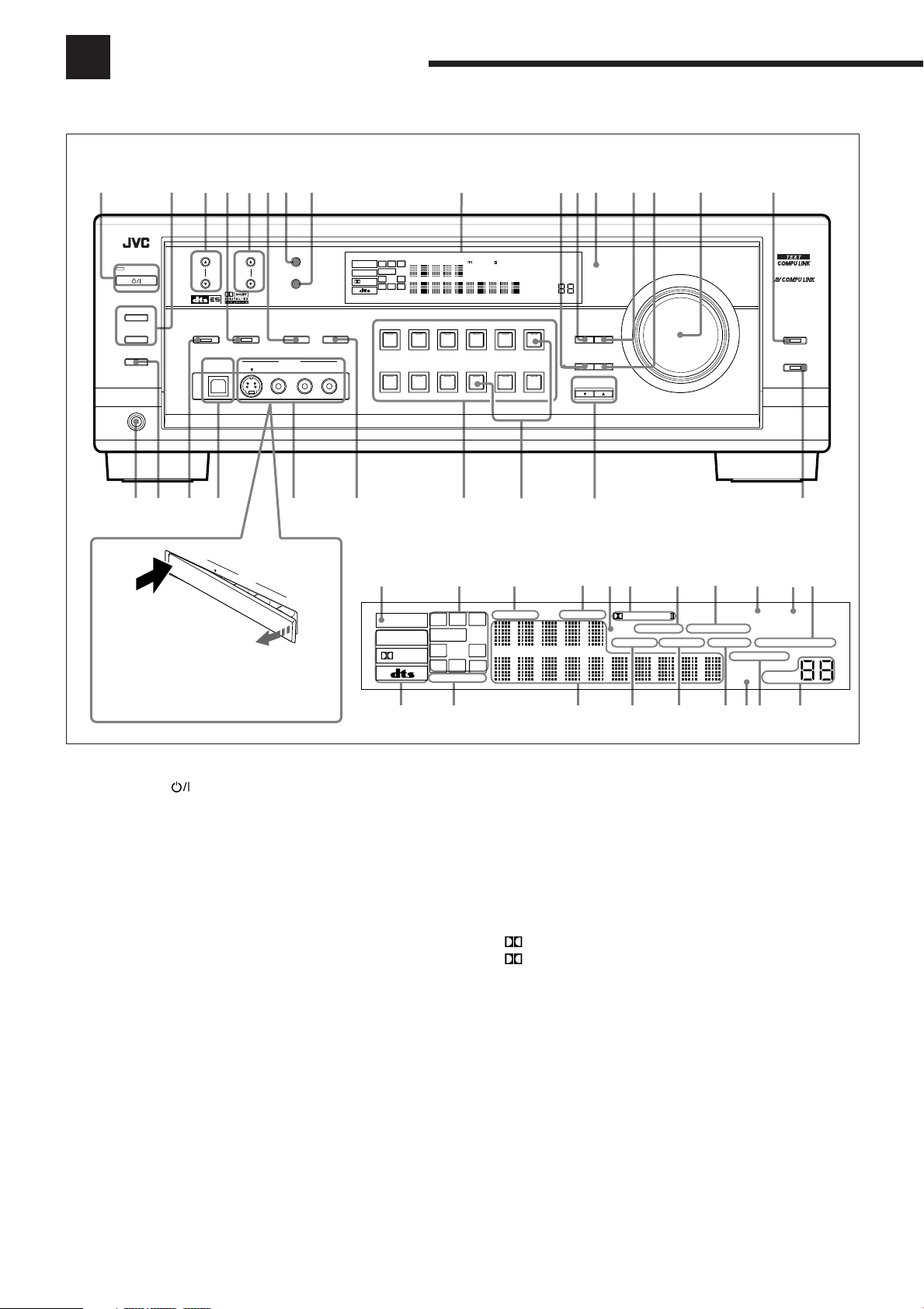
Parts Identification
Become familiar with the buttons and controls on the receiver before use.
Refer to the pages in parentheses for details.
Front Panel
7
5
DSP
S-VIDEO VIDEO
VIDEO
VIDE
6
8
MEMORY
SURROUND/DSP
ANALOG/DIGITAL
OFF
VIDEO
L—AUDIO—R
a;
O
L—
AUDIO—R
STANDBY
STANDBY/ON
SPEAKERS ON/OFF
1
2
SUBWOOFER OUT ON/OFF
PHONES
u
2134
FM/AM TUNING FM/AM PRESET FM MODE
SURROUND
USB AUDIO
i
o
U
S
B
A
U
D
IO
S-VIDEO
PUSH OPEN
When using the VIDEO input jacks and/or
USB AUDIO terminal on the front panel,
detach the front terminal cover.
9q y
RX-8022P
AUDIO/VIDEO CONTROL RECEIVER
INPUT
INPUT ATT
DIGITAL
LS RSCRS
SPEAKERS
SB
12
DGTL AUTO DVD MULTI
L
ANALOG
SUBWFR
LFE
LINEAR PCM
s
SOURCE NAME
d
PRO LOGIC
DSP
HEADPHONE
3D - PHONIC MIDNIGHT MODE
DIGITAL EQ INPUT ATT
TV SOUND/DBSVIDEOVCR 2VCR 1DVDDVD MULTI
SOURCE NAME
f
TUNED STEREO
ONE TOUCH OPERATION
AUTO MUTING
SLEEP VOLUME
FM / AMUSB AUDIOTAPE / MDCDRCDPHONO
w
prt
DIGITAL
EFFECT SETTING
DOWN UP
EQ
CONTROL
LEVEL
ADJUST
e
MASTER VOLUME
g
ANALOG DIRECT
BASS BOOST
h
Display Window
1
ANALOG
LINEAR PCM
DIGITAL
=
2
L
CR
SUBWFR
LS RS
S
SB
SPEAKERS
~
3
DGTL AUTO DVD MULTI
LFE
12
!
4
67
5
PRO LOGIC
3D - PHONIC
DSP
HEADPHONE
DIGITAL EQ INPUT ATT
@
MIDNIGHT MODE
#
8
AUTO MUTING
SLEEP
$%^
9
0
TUNED STEREO
ONE TOUCH OPERATION
VOLUME
&
-
Front Panel
1 STANDBY/ON button and STANDBY lamp (16)
2 • SPEAKERS ON/OFF 1 button (18)
• SPEAKERS ON/OFF 2 button (18)
3 FM/AM TUNING 5 / ∞ buttons (27)
4 DSP button and lamp (36)
5 FM/AM PRESET 5 / ∞ buttons (27, 28)
6 SURROUND/DSP OFF button (36)
7 FM MODE button (28)
8 MEMORY button (27)
9 Display window (16)
p EFFECT button (42)
q DIGITAL EQ (equalization) button (39)
w Remote sensor (15)
e LEVEL ADJUST button (41)
r SETTING button (21)
t MASTER VOLUME control (18)
y ANALOG DIRECT button and lamp (30)
u PHONES jack (18)
i SUBWOOFER OUT ON/OFF button (31)
o SURROUND button and lamp (36)
; USB AUDIO terminal (14)
a VIDEO input jacks (10)
s • INPUT ANALOG/DIGITAL button (19)
• INPUT ATT button (30)
d Source selecting buttons and lamps (16, 17, 19, 27, 28, 37)
DVD MULTI, DVD, VCR 1, VCR 2, VIDEO, TV SOUND/DBS, PHONO,
CD, CDR, TAPE/MD, USB AUDIO, FM/AM
f SOURCE NAME buttons (17)
g CONTROL UP 5/DOWN ∞ buttons (21, 41, 42)
h BASS BOOST button and lamp (31)
Display Window
1 ANALOG indicator (19)
2 Speaker indicators and signal indicators (17)
3 DGTL (digital) AUTO indicator (19)
4 DVD MULTI indicator (37)
5 DSP indicator (18, 34)
6 •
7 3D-PHONIC indicator (33, 34)
8 MIDNIGHT MODE indicator (24)
9 TUNED indicator (27)
0 STEREO indicator (27, 28)
- ONE TOUCH OPERATION indicator (26)
= Digital signal format indicators (19)
~ SPEAKERS 1/2 indicators (18)
! Main Display
@ HEADPHONE indicator (18, 34)
# DIGITAL EQ (equalization) indicator (39)
$ INPUT ATT (attenuator) indicator (30)
% SLEEP indicator (20)
^ AUTO MUTING indicator (28)
& VOLUME level indicator (16, 20)
PRO LOGIC indicator (33)
PRO LOGIC II indicator (32)
•
3
Page 7
Remote Control
1
2
3
4
5
6
7
8
9
p
q
w
e
r
t
CATV/DBS VCR1 TV AUDIO
DVD
TV/DBS VIDEO PHONO
VCR1 VCR2
SURROUND
ANALOG
DIRECT
SOUND
DIMMER
MUTING
CATV/DBS
CONTROL
TV/VIDEO
TEXT
DISPLAY
REC
PAUSE
SLEEP
A/V CONTROL RECEIVER
DVD MULTI
BOOST∗FRONT•L
DIGITAL EQ
∗
RETURN FM MODE 100
CH/
MENU
DOWN – TUNING – UP
DSP
BASS
TEST
7/P
10
+
∗
−
LEVEL
/REW
CD
CDR
TAPE/MD
SURR/DSP
ANALOG/DIGITAL
OFF
231
MENU
CENTER∗SUBWFR
∗
564
ENTER
SURR•L∗SURR•R
∗
89
SBACK•L∗SBACK•R
∗
0
+
TV VOL
−
PLAY
PAUSE
SET
CONTROL
STOP
FM/AM
USB
INPUT
FRONT•R
∗
+10
VOLUME
EXIT
FF/
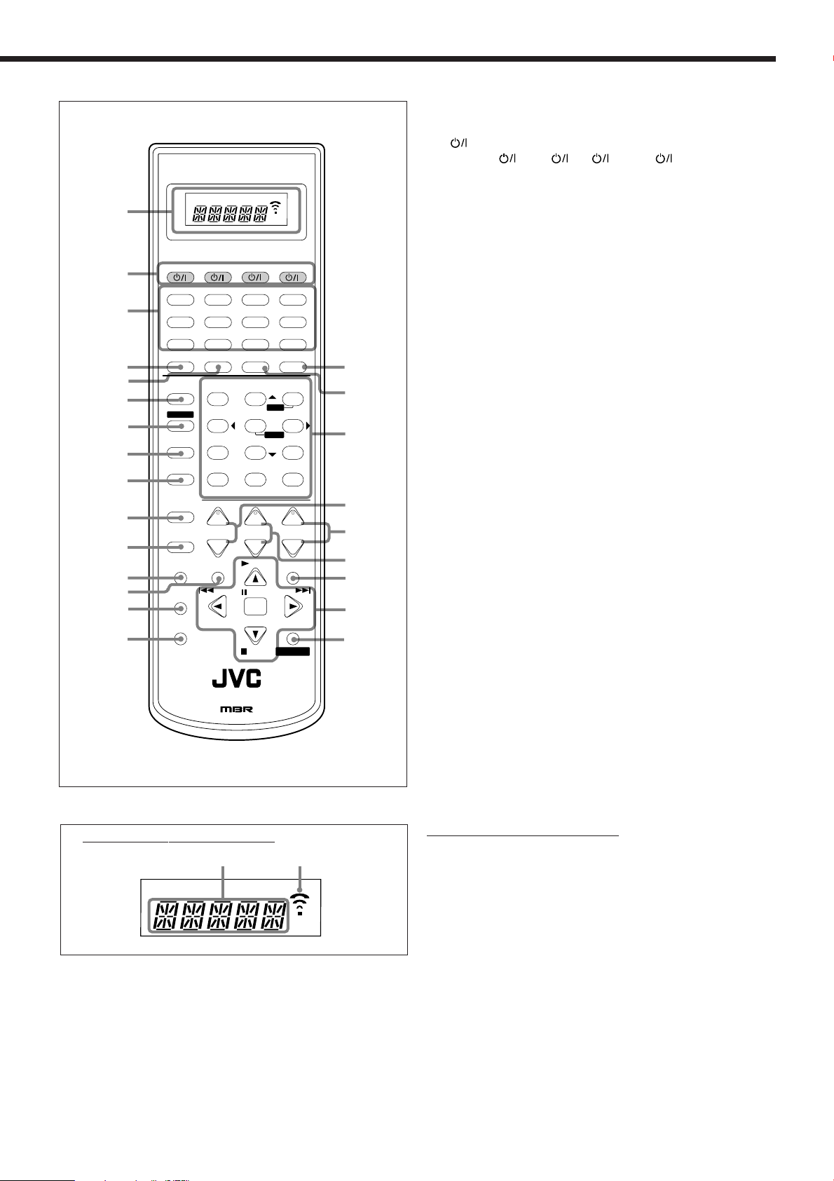
Remote Control
1 Remote control display window
2
buttons (16, 53 – 56)
CATV/DBS
3 Source selecting buttons (16, 17, 19, 27, 28, 37)
DVD, DVD MULTI, CD, FM/AM, TV/DBS, VIDEO, CDR, PHONO,
VCR1, VCR2, TAPE/MD, USB
4 SURROUND button (36)
5 DSP button (36)
6 ANALOG DIRECT button (30)
7 SOUND button (31, 39, 41)
8 DIMMER button (20)
9 MUTING button (20)
p CATV/DBS CONTROL button (55)
q TV/VIDEO button (53)
w TEXT DISPLAY button (45 – 48)
y
u
e MENU button (21, 29 – 31, 38)
r REC PAUSE button (52, 53, 55)
t SLEEP button (20)
y ANALOG/DIGITAL INPUT button (19)
u SURR (surround)/DSP OFF button (36)
i
i • 10 keys for operating tuner (28)
• 10 keys for adjusting sound (31, 39, 41, 51)
• 10 keys for operating audio/video components (51 – 55)
+
o
+
;
−
a
s
o • CH (channel) +/– buttons (53 – 55)
• LEVEL +/– buttons (39, 41)
These buttons function only after pressing 10 keys which are marked with
an asterisk (*).
; VOLUME +/– buttons (18)
a TV VOL (volume) +/– buttons (53, 54)
s EXIT button (21, 29 – 31, 38, 40, 42, 45 – 47)
d • TUNING UP /DOWN buttons (27)
d
• On-screen operating buttons (21, 29 – 31, 38 – 40, 42, 45 – 48)
• Operating buttons for audio/video components (52, 53, 55, 56)
f
f CONTROL button (51 – 53)
, VCR1 , TV , AUDIO
RM-SRX8020J
REMOTE CONTROL
Remote control display window
1
2
Remote control display window
1 Remote control operation mode display (16)
• Remote control operation mode such as “DVD,” “CD,” “SOUND,” etc.
appears.
When the remote control operation mode changes, it is shown on the
display.
2 Signal transmission indicator
• Lights up when transmitting the remote control signals.
4
Page 8
Getting Started
ANTENNA
AM
EXT
AM
LOOP
FM 75
COAXIAL
AM
LO
O
P
ANTENNA
AM
EXT
FM
75
C
O
A
XIA
L
AM
LO
O
P
ANTENNA
AM
EXT
FM
75
C
O
A
XIA
L
This section explains how to connect audio/video components and speakers to the receiver, and how to connect the
power supply.
Before Installation
General Precautions
• Be sure your hands are dry.
• Turn the power off to all components.
• Read the manuals supplied with the components you are going to
connect.
Locations
• Install the receiver in a location that is level and protected from
moisture.
• The temperature around the receiver must be between –5˚C and
35˚C.
• Make sure there is good ventilation around the receiver. Poor
ventilation could cause overheating and damage the receiver.
Handling the receiver
• Do not insert any metal object into the receiver.
• Do not disassemble the receiver or remove screws, covers, or
cabinet.
• Do not expose the receiver to rain or moisture.
Checking the Supplied Accessories
Check to be sure you have all of the following items, which are
supplied with the receiver.
The number in the parentheses indicates quantity of the pieces
supplied.
• Remote Control (1)
• Batteries (2)
• AM Loop Antenna (1)
• FM Antenna (1)
• AC Plug Adaptor (1)
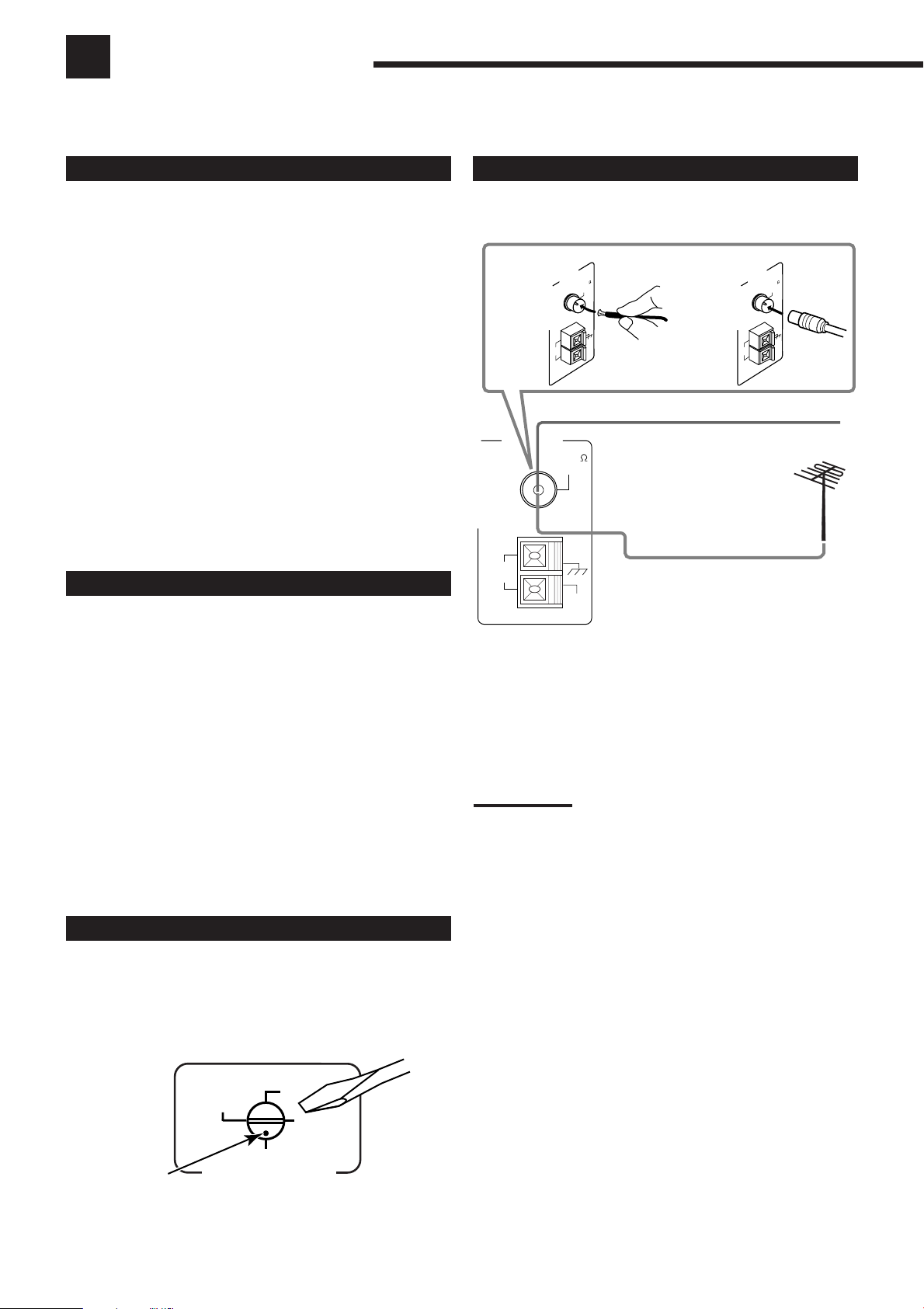
Connecting the FM and AM Antennas
FM Antenna Connections
A
FM Antenna (supplied)
Extend the supplied FM antenna horizontally.
Outdoor FM Antenna Cable (not
supplied)
A. Using the Supplied FM Antenna
The FM antenna provided can be connected to the FM 75 Ω
COAXIAL terminal as temporary measure.
B. Using the Standard Type Connector (not supplied)
A standard type connector should be connected to the FM 75 Ω
COAXIAL terminal.
Note:
If reception is poor, connect the outdoor FM antenna (not supplied).
Before attaching a 75
going to an outdoor antenna), disconnect the supplied FM antenna.
Ω
coaxial cable (the kind with a round wire
B
If anything is missing, contact your dealer immediately.
Setting the Voltage Selector
Before connections, always do the following first if necessary.
Select the correct voltage in VOLTAGE SELECTOR on the rear by
using a screw driver. Check to be sure if the voltage mark is set to
the voltage for your area where this unit plugs in.
220V
Voltage mark
VOLTAGE SELECTOR
110V
230 - 240V
127V
5
Page 9

AM Antenna Connections
Connecting the Speakers
ANTENNA
AM
LOOP
FM 75
COAXIAL
Turn the loop until you have
the best reception.
AM Loop Antenna
(supplied)
AM
EXT
Snap the tabs on the loop into the
slots of the base to assemble the
AM loop.
1
2
3
Outdoor single vinyl-covered wire (not supplied)
Notes:
• If the AM loop antenna wire is covered with vinyl,
remove the vinyl by twisting it as shown in the
diagram.
• Make sure the antenna conductors do not touch any other
terminals, connecting cords and power cord. This could cause poor
reception.
• If reception is poor, connect an outdoor single vinyl-covered wire
(not supplied) to the AM EXT terminal. (Keep the AM loop antenna
connected.)
You can connect the following speakers:
• Two pairs of front speakers to produce normal stereo sound.
• One pair of surround speakers to enjoy the surround effect.
• One surround back speaker or one pair of surround back speakers
to enjoy 6.1-channel sound reproduction.
• One center speaker to produce more effective surround effect (to
emphasize human voices).
• One subwoofer to enhance the bass.
IMPORTANT:
After connecting the speakers listed above, set the speaker
setting information properly to obtain the best possible
Surround and DSP effect. For details, see page 22.
CAUTION:
Use speakers with the SPEAKER IMPEDANCE indicated by the
speaker terminals.
Typical speaker layout
Center speaker
Subwoofer
Left front speaker(s)
Right front speaker(s)
Left surround speakerLeft surround speaker
Surround back speaker(s)
Right surround speaker
6
Page 10
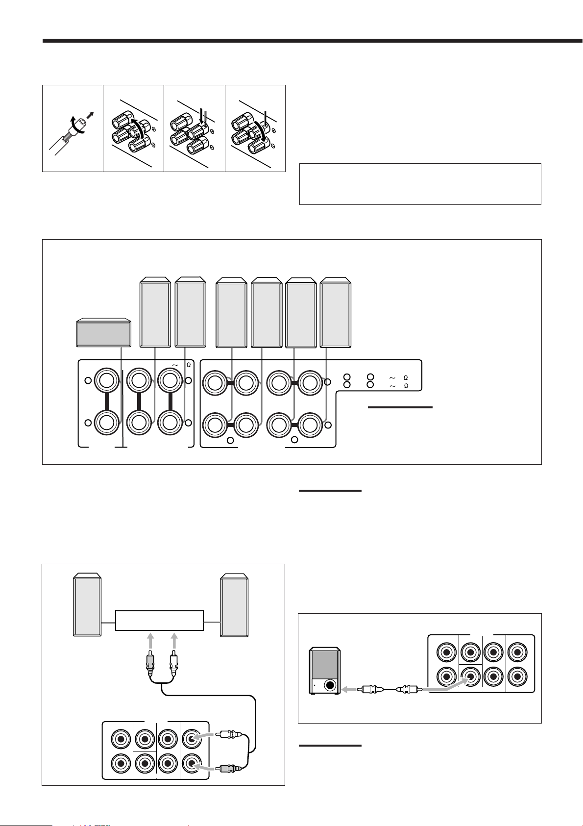
Basic connecting procedure
Powered
subwoofer
R
L
CENTER
SURR
SURR BACK
FRONT
SUBWOOFER
PRE OUT
R
L
1
2
3
4
Connecting the front, center and surround speakers
Surround
Center speaker
speakers
Right / Left
Front speakers 2
Right / Left
Front speakers 1
Right / Left
1 Cut, twist and remove the insulation at the end of
each speaker signal cable (not supplied).
2 Turn the knob counterclockwise.
3 Insert the speaker signal cable.
4 Turn the knob clockwise.
For each speaker (except for a subwoofer), connect the (+) and
(–) terminals on the rear panel to the (+) and (–) terminals
marked on the speakers.
CAUTION : SPEAKER IMPEDANCE
+
–
CENTER
SPEAKER
RIGHT LEFT
SURROUND SPEAKERS
816
+
RIGHT LEFT RIGHT LEFT
–
2
FRONT SPEAKERS
Connecting the surround back speakers
To fully enjoy Dolby Digital EX and DTS-ES Extended Surround
(see pages 32 and 33), you need to connect the surround back
speakers through a power amplifier connected to the PRE OUT
SURR BACK jacks on the rear panel, using a cable with RCA pin
plugs (not supplied). Connect the white plug to the audio left jack,
and the red plug to the audio right jack.
Power amplifier
Left surround
back speaker
Right surround
back speaker
CAUTION : SPEAKER IMPEDANCE
1
+
1
OR
AND
:
2
16
8
:
2
16
32
Note:
You can connect two pairs of front
–
1
speakers (one pair to the FRONT
SPEAKERS
1
terminals, and another pair
to the FRONT SPEAKERS 2 terminals).
Note:
If you have selected “1SPK” for the surround back speaker quantity
(see page 22), connect the surround back speaker to the PRE OUT
SURR BACK L (left) jack.
Connecting the subwoofer speaker
You can enhance the bass by connecting a subwoofer.
Connect the input jack of a powered subwoofer to the PRE OUT
SUBWOOFER jack on the rear panel, using a cable with RCA pin
plugs (not supplied).
7
L
R
FRONT
PRE OUT
CENTER
SUBWOOFER
SURR
SURR BACK
L
R
Note:
You can place a subwoofer wherever you like since bass sound is
non-directional. Normally place it in front of you.
Page 11
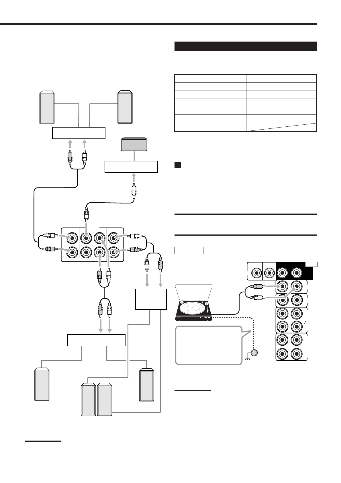
Enhancing your audio system
You can use this receiver as the pre-amplifier (control amplifier)
when you connect power amplifiers to the PRE OUT jacks on the
rear panel using cables with RCA pin plugs (not supplied).
Connect the white plug to the audio left jack, and the red plug to the
audio right jack.
Left front
speaker
Power amplifier
Right front
speaker
Center speaker
Connecting Audio/Video Components
You can connect the following audio/video components to this
receiver. Refer also to the manuals supplied with your components.
Audio Components Video Components
• Turntable • VCRs (VCR 1 and VCR 2)
• CD player* • Video camera
• Cassette deck or • TV*
MD recorder* • DBS tuner*
• CD recorder* • DVD player*
• Personal computer (PC)
*
You can connect these components using the methods described in
“Analog Connections” (see below) and in “Digital Connections” (see
page 13).
FRONT
L
R
SUBWOOFER
Power amplifier
PRE OUT
CENTER
SURR
Power amplifier
SURR BACK
L
R
Power
amplifier
Analog Connections
Audio component connections
Use the cables with RCA pin plugs (not supplied).
Connect the white plug to the audio left jack, and the red plug to the
audio right jack.
CAUTION:
If you connect a sound-enhancing device such as a graphic equalizer
between the source components and this receiver, the sound output
through this receiver may be distorted.
Turntable
Turntable
To audio
output
If a ground cable is
provided for your turntable,
connect the cable to the
screw marked (H) on the
rear panel.
DVD
SUB
WOOFER
CENTER
RIGHT
LEFT
AUDIO
SURR
(REAR)
PHONO
CD
OUT
(REC)
TAPE
MD
IN
(PLAY)
OUT
(REC)
CDR
IN
(PLAY)
Left surround
speaker
Right surround
speaker
Left / Right
Surround back speakers
Note:
If you have selected “1SPK” for the surround back speaker quantity
(see page 22), connect the surround back speaker to the PRE OUT
SURR BACK L (left) jack.
Note:
This connection is for the turntable with an MM (moving-magnet) type
cartridge.
Any turntables incorporating a small-output cartridge such as an MC
(moving-coil) type must be connected to this receiver through a
commercial head amplifier or step-up transformer. Direct connection
may result in insufficient volume.
8
Page 12
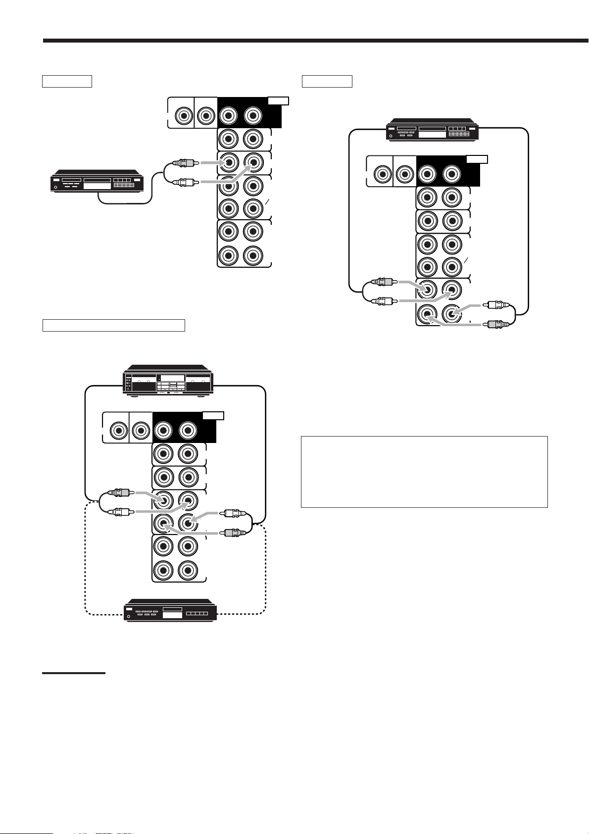
CD player
OUT
(REC)
IN
(PLAY)
IN
(PLAY)
OUT
(REC)
RIGHT
LEFT
PHONO
TAPE
MD
CDR
CD
AUDIO
DVD
SUB
WOOFER
CENTER
SURR
(REAR)
CD recorder
CD player
To audio output
Cassette deck or MD recorder
Cassette deck
To audio input
DVD
SUB
WOOFER
CENTER
RIGHT
To audio output
LEFT
AUDIO
SURR
(REAR)
PHONO
CD
OUT
(REC)
TAPE
MD
IN
(PLAY)
OUT
(REC)
CDR
IN
(PLAY)
To audio input
CD recorder
To audio output
DVD
SUB
WOOFER
CENTER
RIGHT
LEFT
AUDIO
SURR
(REAR)
PHONO
CD
OUT
(REC)
TAPE
MD
IN
(PLAY)
OUT
(REC)
CDR
IN
(PLAY)
To audio outputTo audio input
MD recorder
Note:
You can connect either a cassette deck or an MD recorder to the
TAPE/MD jacks. When connecting an MD recorder to the TAPE/MD
jacks, change the source name to “MD,” which will be shown on the
display when it is selected as the source. See page 17 for details.
If your audio components have a COMPU LINK or TEXT
COMPU LINK jack
• See also page 43 for detailed information about the connection
and the COMPU LINK remote control system.
• See also page 44 for detailed information about the connection
and the TEXT COMPU LINK remote control system.
9
Page 13
Video component connections
S-VIDEO
VIDEO
VIDEO
L—AUDIO—R
Use the cables with RCA pin plugs (not supplied).
Connect the white plug to the audio left jack, the red plug to the
audio right jack, and the yellow plug to the video jack.
• If your video components have S-video (Y/C-separation) and/or
component video (Y, P
B/CB, PR/CR) terminals, connect them using
an S-video cable (not supplied) and/or component video cable (not
supplied). By using these jacks, you can get a better picture
quality in the order—Component video > S-video > Composite
video.
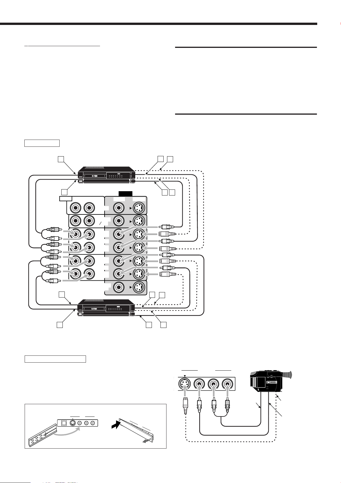
VCR(s)
A
S-VHS/VHS VCR
IMPORTANT:
This receiver is equipped with the following video jacks—composite
video, S-video and component video jacks. You can use any of the
three to connect a video component.
However, the video signals from one type of these input jacks are
output only through the video output jacks of the same type.
Therefore, if a recording video component and a playing video
component are connected to the receiver through the video jacks of
the different type, you cannot record the picture. In addition, if the TV
and a playing video component are connected to the receiver through
the video jacks of the different type, you cannot view the playback
picture on the TV.
C
D
A
B
AUDIO
RIGHT
LEFT
DVD
FRONT
TV SOUND
DBS
OUT
(REC)
VCR1
IN
(PLAY)
OUT
(REC)
VCR2
IN
(PLAY)
MONITOR
OUT
VIDEO
S-VIDEOVIDEO
C
F
E
Å To left/right audio output
ı To left/right audio input
D
Ç To composite video output
Î To S-video output
‰ To composite video input
Ï To S-video input
S-VHS/VHS VCR
B
E
F
Video camera
The VIDEO input jacks on the front panel are convenient when
connecting and disconnecting the equipment frequently.
• When you do not use the terminals on the front panel, attach the
supplied front terminal cover to protect them from dust.
• When attaching the cover
USB AUDIO
S-VIDEO VIDEO
VIDEO
• When removing the cover
L—AUDIO—R
PUSH OPEN
To audio
output
To S-video
output
U
SB
A
U
D
IO
S
-V
ID
E
O
V
V
ID
ID
E
E
O
O
L
—
A
U
D
IO
—
R
To composite
video output
10
Page 14
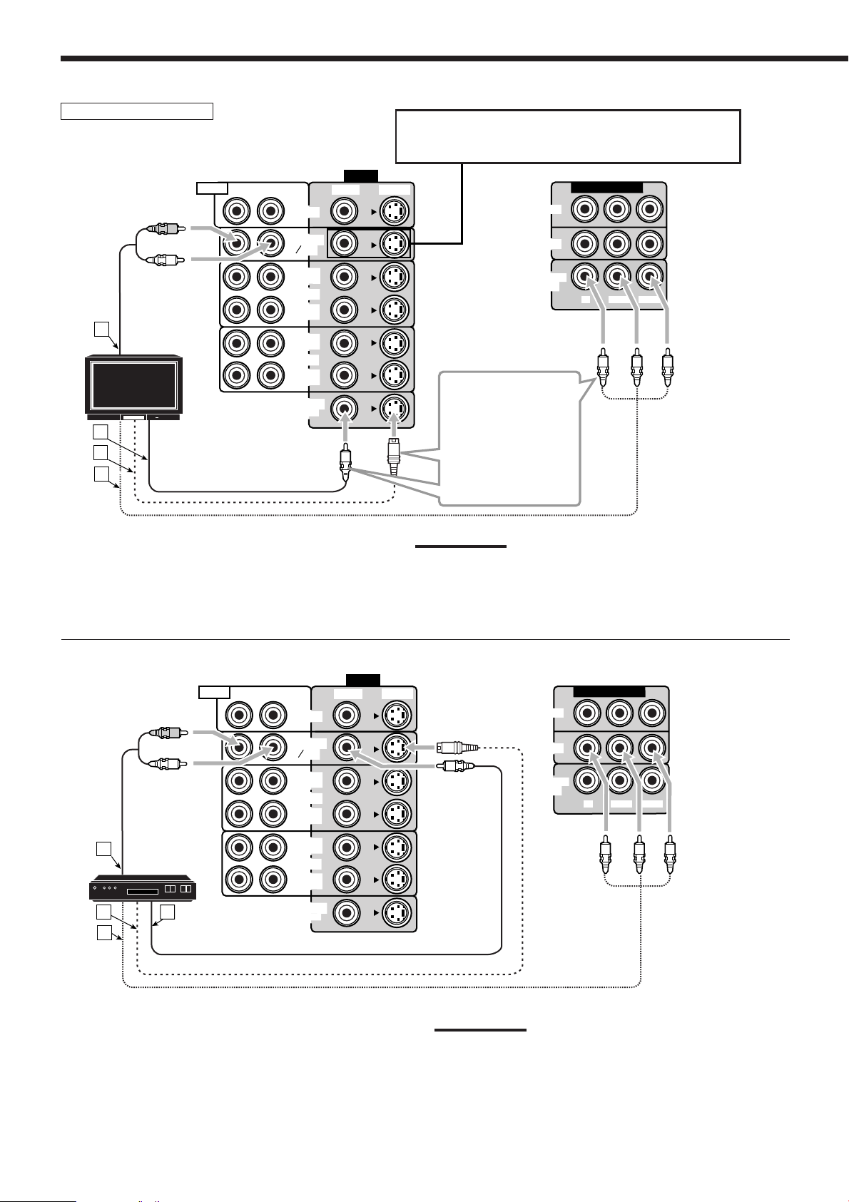
TV and/or DBS tuner
A
TV
B
C
D
AUDIO
RIGHT
LEFT
DVD
FRONT
TV SOUND
DBS
OUT
(REC)
VCR1
IN
(PLAY)
OUT
(REC)
VCR2
IN
(PLAY)
MONITOR
OUT
VIDEO
When connecting the TV to the AUDIO jacks
(TV SOUND/DBS), DO NOT connect the TV’s video output
to these video input jacks.
DVD
DBS
MONITOR
OUT
COMPONENT VIDEO
P
B/CB
Y
PR/C
R
S-VIDEOVIDEO
Connect the TV to the
appropriate MONITOR
OUT jacks to view a
play-backing picture
from other connected
video components.
Å To audio output
ı To composite video input
Ç To S-video input
Î To component video input
AUDIO
A
DBS tuner
DBS
B
D
C
RIGHT
LEFT
DVD
FRONT
TV SOUND
DBS
OUT
(REC)
VCR1
IN
(PLAY)
OUT
(REC)
VCR2
IN
(PLAY)
MONITOR
OUT
VIDEO
Note:
Use a TV of PAL- or multi-color system.
S-VIDEOVIDEO
MONITOR
DVD
DBS
OUT
COMPONENT VIDEO
B/CB
P
Y
PR/C
R
Å To audio output
ı To S-video output
Ç To component video output
Î To composite video output
11
Notes:
• When connecting a DBS tuner to the TV SOUND/DBS jacks,
change the source name to “DBS,” which will be shown on the
display when it is selected as the source. See page 17 for details.
• When connecting a DBS tuner to the component video input jacks,
make the component video input setting correctly. See pages 25
and 49 for details.
Page 15

DVD player
• When you connect a DVD player with stereo output jacks:
AUDIO
RIGHT
LEFT
A
DVD player
DVD
B
D
C
Å To front left/right audio output
ı To S-video output
Ç To component video output
Î To composite video output
DVD
FRONT
TV SOUND
DBS
OUT
(REC)
VCR1
IN
(PLAY)
OUT
(REC)
VCR2
IN
(PLAY)
MONITOR
OUT
VIDEO
DVD
DBS
MONITOR
OUT
COMPONENT VIDEO
PB/CB
Y
PR/CR
S-VIDEOVIDEO
• When you connect a DVD player with its analog discrete output (5.1-channel reproduction) jacks:
DVD player
D
LEFT
FRONT
TV SOUND
MONITOR
E
DVD
DBS
OUT
(REC)
VCR1
IN
(PLAY)
OUT
(REC)
VCR2
IN
(PLAY)
OUT
G
DVD
F
VIDEO
S-VIDEOVIDEO
Å To surround left/right audio output
ı To center audio output
Ç To subwoofer output
Î To front left/right audio output
‰ To composite video output
DVD
SUB
WOOFER
CENTER
RIGHT
B
AUDIO
SURR
(REAR)
PHONO
CD
OUT
(REC)
TAPE
MD
IN
(PLAY)
OUT
(REC)
CDR
IN
(PLAY)
C
RIGHT
A
LEFT
Ï To S-video output
Note:
When connecting a DVD player to the component video input jacks,
make the component video input setting correctly. See pages 25 and 49
for details.
Ì To component video output
DVD
DBS
MONITOR
OUT
COMPONENT VIDEO
B/CB
P
Y
PR/C
R
12
Page 16

PCM/DOLBY DIGITAL
/DTS
DIGITAL OUT
Digital Connections
This receiver is equipped with four DIGITAL IN terminals—one
digital coaxial terminal and three digital optical terminals—and one
DIGITAL OUT terminal.
IMPORTANT:
• When connecting a DVD player, digital TV broadcast tuner or DBS
tuner using the digital terminals, you also need to connect it to the
video jacks on the rear. Without connecting it to the video jacks, you
can view no playback picture.
• After connecting the components using the DIGITAL IN terminals,
set the following correctly if necessary.
– Set the digital input (DIGITAL IN) terminal setting correctly. For
details, see “6 Setting the Digital Input (DIGITAL IN) Terminals”
on page 25.
– Select the digital input mode correctly. For details, see “Selecting
the Analog or Digital Input Mode” on page 19.
Notes:
• When shipped from the factory, the DIGITAL IN terminals have
been set for use with the following components:
– DIGITAL 1 (coaxial): For DVD player
– DIGITAL 2 (optical): For CD player
– DIGITAL 3 (optical): For digital TV broadcast tuner
– DIGITAL 4 (optical): For CD recorder
• When you want to operate the CD player, CD recorder, or MD
recorder using the COMPU LINK remote control system, connect
the target component also as described in “Analog Connections”
(see page 9).
• When you want to operate a DVD player using the AV COMPU
LINK remote control system (see page 49), connect the DVD player
also as described in “Analog Connections” (see page 12).
Digital input terminals
You can connect any digital equipment as follows:
Digital TV
DVD player
DVD
CD recorder
MD recorder
Digital coaxial cable (not supplied)
between digital coaxial terminals
Digital optical cable (not supplied)
between digital optical terminals
DBS tuner
Digital VCR
DBS
CD player
Digital output terminal
CD recorder
Digital optical cable (not supplied)
between digital optical terminals
When the digital recording
equipment such as an MD recorder
and CD recorder has a digital
optical input terminal, connecting it
to the DIGITAL OUT terminal
enables you to perform digital-todigital recording.
MD recorder
When the component has a digital
coaxial output terminal, connect it to the
DIGITAL 1 (DVD) terminal, using a
digital coaxial cable (not supplied).
When the component has a digital
optical output terminal, connect it to the
DIGITAL 2 (CD), DIGITAL 3 (TV) or
DIGITAL 4 (CDR) terminal, using a
digital optical cable (not supplied).
Before connecting a digital
optical cable, unplug the
protective plug.
13
Note:
The digital signal format output through the DIGITAL OUT terminal is
the same as that of the input signal. This means that when the DTS
Digital Surround signals are input, the DTS Digital Surround signals
are output.
DIGITAL IN
DIGITAL 1 (DVD)
DIGITAL 2 (CD)
DIGITAL 3 (TV)
DIGITAL 4 (CDR)
Page 17
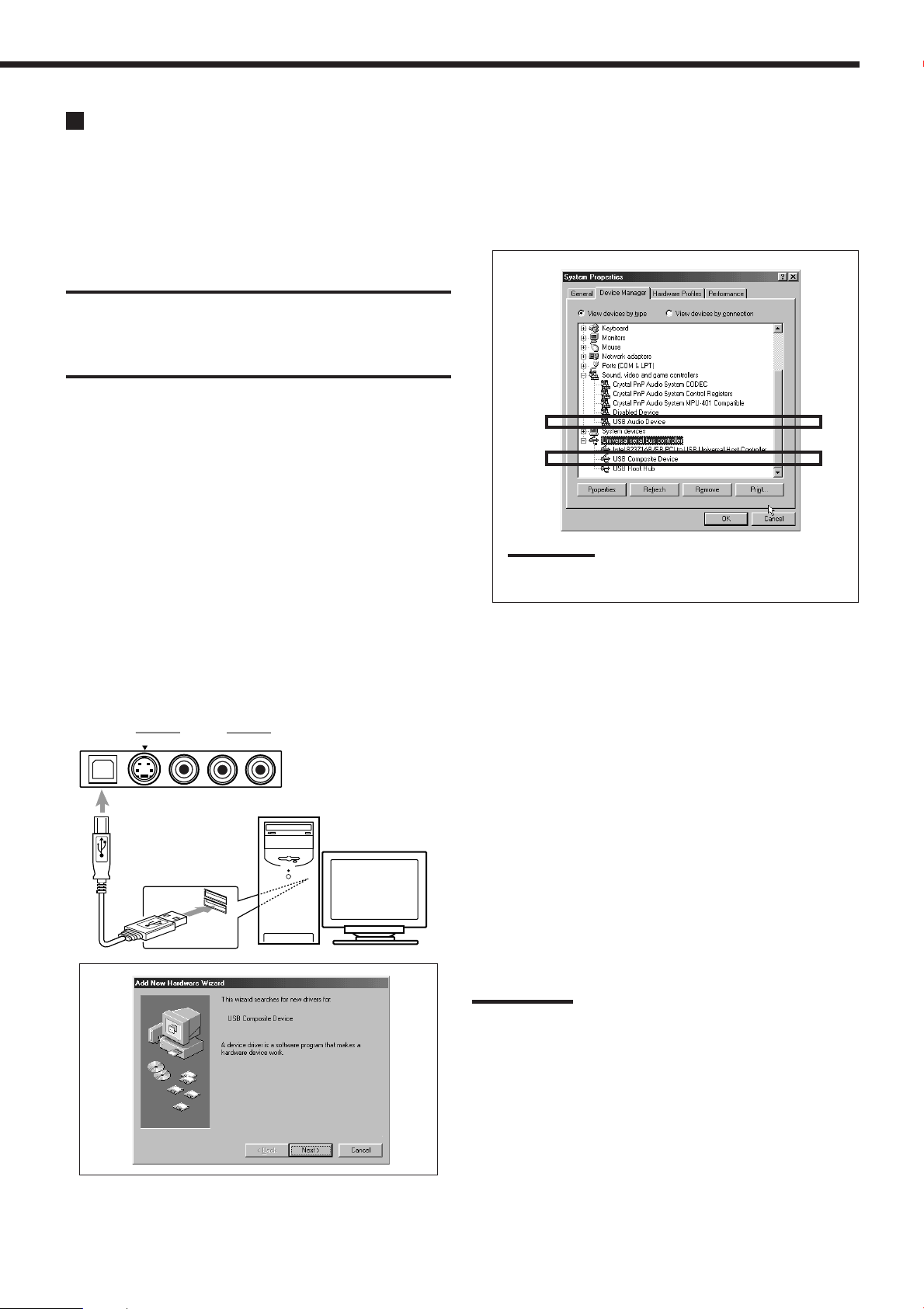
USB Connection
This receiver is equipped with a USB terminal on the front panel.
You can connect your PC to this terminal and enjoy sound
reproduced through your PC.
When you connect your PC for the first time, follow the procedure
below.
• Remember you cannot send any signal or data to your PC from
this receiver.
IMPORTANT:
• Check if your PC equipped with the CD-ROM drive is running on
Windows
CD-ROM.
• Check your PC’s BIOS setting—whether USB is available, and
whether USB IRQ is set to “AUTO” or to available IRQ number.
R
98*, WindowsR Me* or WindowsR XP* and prepare its
How to install the USB drivers
The following procedure is described using the English version of
Windows
operation system or language, the screens shown on your PC’s
monitor will differ from the ones used in the following procedure.
R
98. If your PC is running on a different version of
5. Check if the drivers are correctly installed.
1. Open the Control Panel on your PC: Select [Start] =
[Settings] = [Control Panel].
2. Select [System], then [Device Manager] and click [Sound,
video and game controllers] and [Universal serial bus
controller].
The following window appears, and you can check whether
the drivers are installed.
1. Turn on your PC and start running Windows
Windows
R
Me or WindowsR XP.
R
98,
If the PC has been turned on, quit all the applications now running.
2. Turn on the receiver, and press USB AUDIO on the front
panel or USB on the remote control.
The lamp on the USB AUDIO button on the front panel lights
up.
3. Connect the receiver to the PC using a USB cable (not
supplied).
Your PC automatically recognizes this connection, and shows
the following screen on the monitor.
USB AUDIO
S-VIDEO
VIDEO
VIDEO
L—AUDIO—R
PC
USB cable
(not supplied)
Note:
The items shown on the PC’s monitor differ depending on
your PC settings.
6. Change the PC audio setting.
1. If you have closed Control Panel, open it again: Select [Start]
= [Settings] = [Control Panel].
2. Click [Multimedia], then select “USB Audio Device [1]” for
“Playback” of “Audio,” and close the window.
To play back a CD from CD-ROM drive on PC, click [Multimedia],
[CD Music], then check [Enable digital CD audio for this CD-ROM
device].
Now PC is ready for playback through the USB connection.
After installation is completed, you can use your PC as the playback
source. The PC automatically recognizes the receiver whenever a
USB cable is connected between the PC and the receiver while the
receiver is turned on.
• When not using the PC as the playback source, disconnect the
USB cable.
To play back sounds on the PC, refer to the manuals supplied with
the sound reproduction application installed in the PC.
4. Install the USB drivers following the instructions shown on
the PC’s monitor.
Notes:
• DO NOT turn off the receiver or disconnect the USB cable while
installing the drivers and for several seconds while your PC is
recognizing the receiver.
• Use a full speed USB cable (revision 1.0). Recommended cord
length is 1.5 m.
• If your PC does not recognize the receiver, disconnect the USB
cable and connect it again. If it does not work yet, restart Windows.
• The installed drivers can be recognized only when the USB cable is
connected between the receiver and your PC.
• The sound may not be played back correctly—interrupted or
degraded—due to your PC settings and PC specifications.
• When you do not use the terminals on the front panel, attach the
supplied front terminal cover to protect them from dust.
*
MicrosoftR, WindowsR 98, WindowsR Me and WindowsR XP are
registered trademarks of Microsoft Corporation.
14
Page 18
Connecting the Power Cord
Putting Batteries in the Remote Control
Before plugging the receiver into an AC outlet, make sure that all
connections have been made.
Plug the power cord into an AC outlet.
Keep the power cord away from the connecting cables and the
antenna. The power cord may cause noise or screen interference. We
recommend that you use a coaxial cable to connect the antenna,
since it is well-shielded against interference.
Note:
The preset settings such as preset channels and sound adjustment
may be erased in a few days in the following cases:
– When you unplug the power cord.
– When a power failure occurs.
CAUTIONS:
• Do not plug in before setting the voltage selector switch on the rear
of the unit and all connection procedures are complete.
• Do not touch the power cord with wet hands.
• Do not pull on the power cord to unplug the cord. When unplugging
the cord, always grasp the plug so as not to damage the cord.
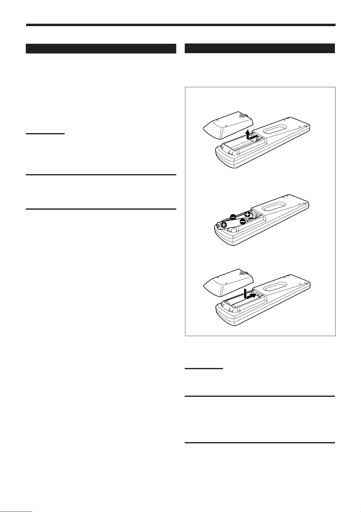
Before using the remote control, put two supplied batteries first.
When using the remote control, aim the remote control directly at
the remote sensor on the receiver.
1. On the back of the remote control, remove the
battery cover.
2. Insert batteries. Make sure to match the
polarity: (+) to (+) and (–) to (–).
R6P(SUM-3)/AA(15F)
3. Replace the cover.
If the range or effectiveness of the remote control decreases, replace
the batteries. Use two R6P(SUM-3)/AA(15F) type dry-cell batteries.
Note:
After replacing the batteries, set the manufacturers’ codes again (see
page 54).
CAUTION:
Follow these precautions to avoid leaking or cracking cells:
• Place batteries in the remote control so they match the polarity:
(+) to (+) and (–) to (–).
• Use the correct type of batteries. Batteries that look similar may
differ in voltage.
• Always replace both batteries at the same time.
• Do not expose batteries to heat or flame.
15
Page 19
Basic Operations
The following operations are commonly used when you play any sound sources.
Before using the remote control
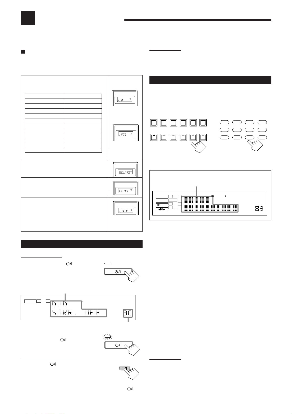
How to confirm the remote control operation mode
The display window on the remote control shows the following
information when you press certain buttons on the remote control, so
that you can confirm which operation you do.
Pressing one of the source selecting buttons,
the source name selected appears on the
display.
Buttons
FM/AM
CD
PHONO
TAPE/MD
DVD or DVD MULTI
CDR
USB
TV/DBS
VCR1
VCR2
VIDEO
Indications
TUNER
CD
PHONO
TAPE
DVD
CDR
USB
TV
VCR1
VCR2
VIDEO
Pressing SOUND before you adjust the sound
A/V CONTROL RECEIVER
Ex.: When you
press CD.
A/V CONTROL RECEIVER
Ex.: When you
press USB.
A/V CONTROL RECEIVER
effect, “SOUND” appears on the display.
Pressing TEXT DISPLAY or MENU before
you use on-screen menu or TEXT COMPU
A/V CONTROL RECEIVER
LINK, “MENU” appears on the display.
Pressing CONTROL or CATV/DBS
A/V CONTROL RECEIVER
CONTROL before you operate an audio or
video equipment connected to the receiver,
the remote control operation mode selected
appears on the display (see pages 51 and 54).
Ex.: When you
press CATV/
DBS CONTROL.
Turning On the Power
On the front panel:
Press STANDBY/ON .
The STANDBY lamp goes off. The name of
the current source and Surround/DSP mode
appear on the display.
Current source name and Surround/DSP mode appear
L R
ANALOG
SPEAKERS
1
Current volume level appears
To turn off the power (into standby mode),
press STANDBY/ON
again.
The STANDBY lamp lights up.
From the remote control:
Press AUDIO .
The STANDBY lamp on the front panel goes off.
The name of the current source and Surround/DSP
mode appear on the display.
To turn off the power (into standby mode), press AUDIO
again. The STANDBY lamp on the front panel lights up.
STANDBY
STANDBY/ON
VOLUME
STANDBY
STANDBY/ON
AUDIO
Note:
A small amount of power is consumed in standby mode. To turn the
power off completely, unplug the AC power cord.
Selecting the Source to Play
Press one of the source selecting buttons.
The lamp on the front panel button for selected source lights up.
• The selected source name and the previously selected Surround/
DSP mode also appear on the display.
TV SOUND/DBSVIDEOVCR 2VCR 1DVDDVD MULTI
SOURCE NAME
FM / AMUSB AUDIOTAPE / MDCDRCDPHONO
SOURCE NAME
On the front panel
Selected source name and current
Surround/DSP mode appear
ANALOG
LINEAR PCM
DIGITAL
L
SUBWFR
LS RSCRS
SPEAKERS
DGTL AUTO DVD MULTI
LFE
SB
12
PRO LOGIC
DSP
HEADPHONE
DVD MULTI :Select the DVD player for viewing a DVD
using the analog discrete output mode
(5.1-channel reproduction).
To enjoy the DVD MULTI playback, see
page 37.
DVD :Select the DVD player.
VCR 1 :Select the video component connected to the
VCR 1 jacks.
VCR 2 :Select the video component connected to the
VCR 2 jacks.
VIDEO :Select the video component connected to the
VIDEO jacks.
TV (SOUND)/DBS :Select TV sounds (or the DBS tuner).
PHONO
CD
CDR
TAPE/MD
*:Select the turntable.
*:Select the CD player.
* :Select the CD recorder.
*:Select the cassette deck (or the MD recorder).
USB (AUDIO) :Select the personal computer (PC) connected
to the USB terminal.
FM/AM
*:Select an FM or AM broadcast.
• Each time you press the button, the band
alternates between FM and AM.
Notes:
• When connecting an MD recorder (to the TAPE/MD jacks) and a
DBS tuner (to the TV SOUND/DBS jacks), change the source
names shown on the display. For details, see page 17.
• When you press one of the source selecting buttons on the remote
control marked with an asterisk (*) above, the receiver
automatically turns on.
DVD MULTIDVD
TV/DBS VIDEO PHONO
VCR 1 VCR 2
CD
CDR
TAPE/MD
FM/AM
From the remote control
3D–PHONIC MIDNIGHT MODE
TUNED STEREO
DIGITAL EQ INPUT ATT
AUTO MUTING
ONE TOUCH OPERATION
SLEEP VOLUME
USB
16
Page 20
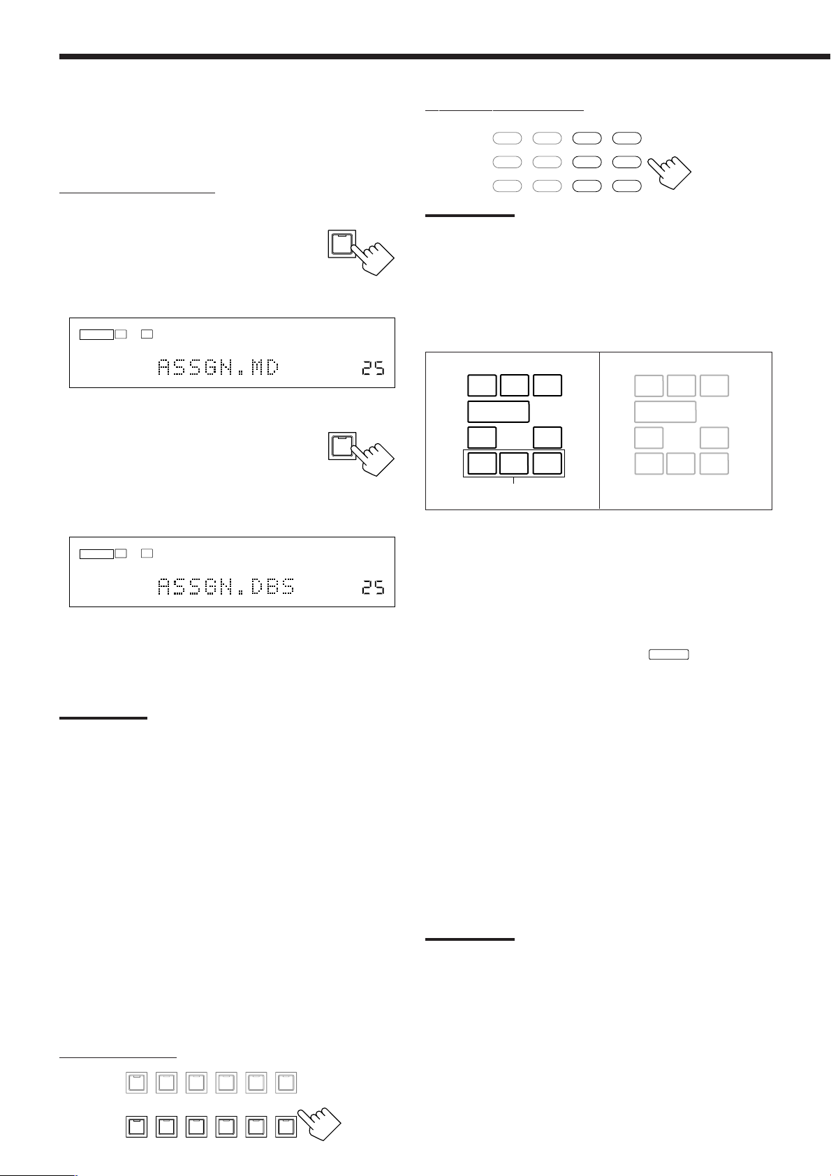
Changing the source name
DVD MULTI
DVD
USB
CD
CDR
TAPE/MD
TV/DBS VIDEO PHONO
FM/AM
VCR 1 VCR 2
L
SUBWFR
LS RS
CR
S
LFE
SB
L
LS RS
CR
SB
SUBWFR
LFE
S
When you have connected an MD recorder to the TAPE/MD jacks
or a DBS tuner to the TV SOUND/DBS jacks on the rear panel,
change the source name which will be shown on the display.
On the front panel ONLY:
When changing the source name from “TAPE” to “MD”:
1. Press TAPE/MD (SOURCE NAME).
• Make sure “TAPE” appears on the display.
2. Press and hold SOURCE NAME
TAPE / MD
SOURCE NAME
(TAPE/MD) until “ASSGN. MD”
appears on the display.
L R
ANALOG
From the remote control:
Note:
Once you have selected a video source, pictures of the selected
source are sent to the TV until you select another video source.
Speaker and signal indicators on the display
By checking the following indicators, you can easily confirm which
speakers you are activating and which signals are coming into this
receiver from the source.
SPEAKERS
1
VOLUME
When changing the source name from “TV” to “DBS”:
1. Press TV SOUND/DBS (SOURCE
TV SOUND/DBS
NAME).
• Make sure “TV” appears on the display.
SOURCE NAME
2. Press and hold SOURCE NAME (TV
SOUND/DBS) until “ASSGN. DBS”
appears on the display.
L R
ANALOG
SPEAKERS
1
VOLUME
To change the source name to “TAPE” or “TV,” repeat the same
procedure above—press and hold SOURCE NAME (TAPE/MD) to
select “TAPE,” or press and hold SOURCE NAME (TV SOUND/
DBS) to select “TV.”
Note:
Without changing the source name, you can still use the connected
components. However, there may be some inconvenience.
–“TAPE” or “TV” will appear on the display when you select the MD
recorder or DBS tuner.
– You cannot use the digital input mode (see page 19) for the MD
recorder.
– You cannot use the COMPU LINK remote control system (see page
43) to operate the MD recorder.
Selecting different sources for picture and
sound
You can watch picture from a video component while listening to
sound from another component.
Press one of the audio source selecting buttons— PHONO,
CD, CDR, TAPE/MD, USB (AUDIO), FM/AM—while
viewing the picture from a video component such as the
VCR or DVD player, etc.
The lamp on the front panel button for the selected source lights up.
Speaker indicators (white)
Signal indicators (red)
Surround back speaker
indicators *
The speaker indicators light up—:
• When the corresponding speakers are set to “LARGE” or
“SMALL” (see “1 Setting the Speakers” on page 22) and are also
required for the Surround/DSP mode currently selected.
If you have selected “1SPK” for the surround back speaker quantity
*
(see page 22), the center surround back speaker indicator lights up.
If you have selected “2SPK,” the left and right surround back
speaker indicators light up.
• When “SUBWOOFER” is set to “YES,”
SUBWFR
lights up. (See
“1 Setting the Speakers” on page 22.)
The signal indicators light up to indicate the incoming signals.
L : • When digital input is selected: Lights up when the left
channel signal comes in.
• When analog input is selected: Always lights up.
R : • When digital input is selected: Lights up when the right
channel signal comes in.
• When analog input is selected: Always lights up.
C : Lights up when the center channel signal comes in.
LFE : Lights up when the LFE channel signal comes in.
LS : Lights up when the left surround channel signal comes in.
RS : Lights up when the right surround channel signal comes in.
S : When the monaural rear channel signal or 2 channel Dolby
Surround encoded signal comes in.
SB : Lights up when the surround back channel signal comes in.
Note:
When “DVD MULTI” is selected as the source, “L,” “C,” “R,” “LFE,” “LS”
and “RS” light up.
On the front panel:
DVD MULTI
17
VCR 1
DVD
SOURCE NAME
VIDEO
VCR 2
USB AUDIOTAPE / MDCDRCDPHONO
TV SOUND/DBS
SOURCE NAME
FM / AM
Page 21

Adjusting the Volume
Listening Only with Headphones
On the front panel:
To increase the volume, turn MASTER
MASTER VOLUME
VOLUME clockwise.
To decrease the volume, turn it
counterclockwise.
From the remote control:
To increase the volume, press VOLUME +.
To decrease the volume, press VOLUME –.
+
VOLUME
−
CAUTION:
Always set the volume to the minimum before starting any sources. If
the volume is set at its high level, the sudden blast of sound energy
can permanently damage your hearing and/or ruin your speakers.
Notes:
• The volume level can be adjusted within the range of “0” (minimum)
to “70” (maximum).
• If you set One Touch Operation to “ON” (see page 26), you do not
have to adjust the volume level each time you change the source. It
is automatically set to the stored level.
You can listen with the headphones without deactivating both pairs
of speakers by connecting a pair of headphones to the PHONES jack
on the front panel. If you want to use a pair of headphones without
outputting sounds from the front speakers, you must turn off both
pairs of the front speakers as mentioned above.
HEADPHONE mode
When using the headphones, the following signals are output
regardless of your speaker setting:
— For 2 channel software, the front left and right channel signals
are output directly from the headphones.
— For multi-channel software, the front left and right, center, and
surround channel signals are down-mixed and then output
from the headphones.
• If a DSP mode is activated, you can enjoy the DSP effects.
“3D H.PHONE” appears on the display and the DSP indicator
lights up on the display. (See page 34.)
Note:
In the following cases, the speakers connected to the FRONT
SPEAKERS 2 terminals are deactivated even if both pairs of the front
speakers are activated.
– If you select “DVD MULTI” as the source.
– If you select any of the Surround/DSP modes which activate the
center and/or surround speaker(s).
Selecting the Front Speakers
On the front panel ONLY:
When you have connected two pairs of the front speakers, you can
select which to use.
To use the speakers connected to the
FRONT SPEAKERS 1 terminals, press
SPEAKERS ON/OFF 1 so that the
SPEAKERS 1 indicator lights up on the
display. Make sure that the SPEAKERS 2
indicator is not lit on the display.
To use the speakers connected to the FRONT SPEAKERS 2
terminals, press SPEAKERS ON/OFF 2 so that SPEAKERS 2
indicator lights up on the display. Make sure that the SPEAKERS 1
indicator is not lit on the display.
To use both sets of the speakers, press SPEAKERS ON/OFF 1 and
SPEAKERS ON/OFF 2 so that the SPEAKERS 1 and SPEAKERS 2
indicators light up on the display.
To use neither sets of the speakers, press SPEAKERS ON/OFF 1
and SPEAKERS ON/OFF 2 so that the SPEAKERS 1 and
SPEAKERS 2 indicators disappear from the display.
The HEADPHONE indicator lights up and “HEADPHONE”
appears on the display.
• Activating the speakers turns on the Surround and DSP modes
previously selected.
SPEAKERS ON/OFF
1
2
CAUTION:
Be sure to turn down the volume:
• Before connecting or putting on headphones, as its high volume can
damage both the headphones and your hearing.
• Before turning on speakers again, as its high volume may output
from the speakers.
18
Page 22

VOLUME
DIGITAL
L R
SPEAKERS
DGTL AUTO
1
DGTL AUTO DGTL D.D
DGTL DTS
(Digital Dolby Digital)
(Digital)
(Digital)
Selecting the Analog or Digital Input
Mode
When you have connected digital source components using the
digital terminals (see page 13), you need to change the input mode
for these components to the appropriate digital input mode
correctly—DGTL AUTO, DGTL DTS, or DGTL D.D.
Before you start, remember...
The digital input (DIGITAL IN) terminal setting should be
correctly done for the sources you want to select the digital input
mode for (see “6 Setting the Digital Input (DIGITAL IN)
Terminals” on page 25). Without setting this digital input terminal
correctly, you cannot change the input mode from analog input to
digital input even if you follow the procedure below.
1. Press one of the source selecting buttons—DVD, TV
(SOUND)/DBS, CD, CDR or TAPE/MD—for which you
want to change the input mode.
The lamp on the front panel button for the selected source lights
up.
DVDDVD MULTI
VCR 1
SOURCE NAME
On the front panel
Note:
If “TAPE” has been assigned as the source name to the TAPE/MD
button when using an MD recorder, it does not work in this step.
To change the source name, see “Changing the source name” on
page 17.
TV SOUND/DBSVIDEOVCR 2
SOURCE NAME
USB AUDIOTAPE / MDCDRCDPHONO
DVD
DVD MULTI
TV/DBS VIDEO PHONO
FM / AM
VCR 1 VCR 2
CD
CDR
TAPE/MD
FM/AM
USB
From the remote control
DGTL AUTO: Select this for the digital input mode. The
receiver automatically detects the incoming
signals.
The DGTL AUTO indicator lights up on the
display, and the digital signal format indicators
for the detected signals also light up.
ANALOG: Select this for the analog input mode.
The ANALOG indicator lights up.
When selecting “DGTL AUTO,” the following indicators
showing detected signals light up on the display.
LINEAR PCM
: Lights up when Linear PCM signals come
in.
LINEAR PCM
: Lights up when the digital signals are not
recognized.
DIGITAL
: Lights up when Dolby Digital or Dolby
Digital EX signals come in.
: Lights up when DTS Digital Surround or
DTS-ES signals come in.
When playing a software encoded with the Dolby Digital or DTS
Digital Surround, the following symptoms may occur:
• Sound does not come out at the beginning of playback.
• Noise comes out while chapters or tracks are being searched for or
skipped over.
1. Press INPUT ANALOG/DIGITAL (INPUT ATT) or
ANALOG/DIGITAL INPUT on the remote control.
•“DGTL AUTO” appears on the display.
2. Press CONTROL UP 5 or DOWN ∞ on the front panel to
select “DGTL D.D” or “DGTL DTS” while “DGTL AUTO”
still remains on the display.
• Each time you press the button, the input mode changes as
follows:
2. Press INPUT ANALOG/DIGITAL (INPUT ATT)—or
ANALOG/DIGITAL INPUT on the remote control—
briefly to change the input mode.
INPUT
ANALOG/DIGITAL
INPUT ATT
On the front panel
• Each time you press the button, the input mode changes as
follows:
DGTL AUTO
L R
DIGITAL
1
SPEAKERS
DGTL AUTO
(Digital)
19
ANALOG/DIGITAL
INPUT
From the remote control
ANALOG
VOLUME
When selecting “DGTL D.D” or “DGTL DTS,” the following
indicators showing detected signals light up on the display.
DGTL : Always lights up.
When selecting “DGTL D.D”
DIGITAL
: • Lights up when Dolby Digital signals
come in.
• The frame flashes when Dolby Digital
signals are not recognized.
When selecting “DGTL DTS”
: • Lights up when DTS Digital Surround
signals come in.
• The frame flashes when DTS Digital
Surround signals are not recognized.
Note:
When you turn off the power or select another source, “DGTL D.D”
and “DGTL DTS” settings are canceled and the digital input mode is
automatically reset to “DGTL AUTO.”
Page 23

Muting the Sound
When the shut-off time comes:
The receiver turns off automatically.
From the remote control ONLY:
Press MUTING to mute the sound through
MUTING
all speakers and headphones connected.
“MUTING” appears on the display and the volume
turns off (the volume level indicator goes off).
L R
ANALOG
SPEAKERS
1
Ex.: When the source is “DVD.”
The volume level
indicator goes off.
To restore the sound, press MUTING again.
• Turning MASTER VOLUME on the front panel or pressing
VOLUME +/– on the remote control also restores the sound.
Changing the Display Brightness
You can dim the display.
From the remote control ONLY:
Press DIMMER.
DIMMER
• Each time you press the button, the display dims
and brightens alternately.
Using the Sleep Timer
Using the Sleep Timer, you can fall asleep while listening to music.
From the remote control ONLY:
Press SLEEP repeatedly.
The SLEEP indicator lights up on the display, and
the shut-off time changes in 10 minutes intervals.
L R
ANALOG
1
SPEAKERS
2010 30 40 50 60 70 80 90
(Canceled)
0
Ex.: When the source is “DVD.”
SLEEP
SLEEP VOLUME
To check or change the time remaining until the shut-off time:
Press SLEEP once.
The remaining time until the shut-off time appears in minutes.
• To change the shut-off time, press SLEEP repeatedly.
To cancel the Sleep Timer:
Press SLEEP repeatedly until “SLEEP 0min” appears on the display.
(The SLEEP indicator goes off.)
• Turning off the power also cancels the Sleep Timer.
Recording a source
For analog-to-analog recording
You can record any analog source through the receiver to—
• the cassette deck (or MD recorder) connected to the TAPE/MD
jacks,
• the VCRs connected to the VCR 1 and VCR 2 jacks, and
• the CD recorder connected to the CDR jacks
—at the same time.
For digital-to-digital recording
You can record the currently selected digital input source
through the receiver to a digital recording device connected to
the DIGITAL OUT terminal.
Notes:
• Analog-to-digital and digital-to-analog recordings are not
possible.
• The output volume level, Midnight Mode (see page 24), Bass
Boost (see page 31), digital equalization (see page 39),
Surround modes and DSP modes (see pages 32 to 36) cannot
affect the recording.
• The test tone signal (see pages 40 and 41) does not come out
through the DIGITAL OUT terminal.
Basic adjustment auto memory
This receiver memorizes sound settings for each source—
• when you turn off the power,
• when you change the source, and
• when you assign the source name (see page 17).
When you change the source, the memorized settings for the
newly selected source are automatically recalled.
The following can be stored for each source:
• Analog/digital input mode (see page 19)
• Input attenuator mode (see page 30)
• Analog Direct (see page 30)
• Speaker channel output levels (see pages 40 and 41)
• Digital equalization pattern (see page 39)
• Sound parameters (see page 42)
• Surround and DSP mode selection (see pages 35 and 36)
• Bass Boost setting (see page 31)
Notes:
• If the source is FM or AM, you can assign a different setting for
each band.
• If you want to memorize the volume level with the above
settings, set “ONE TOUCH (OPR)” to “ON” (see page 26).
20
Page 24

Basic Settings
Some of the following settings are required after connecting and positioning your speakers while others will make
operations easier.
• When performing the basic settings, it is recommended to use the remote control so that you can show the
on-screen display on the TV.
• When using the buttons on the front panel, you can perform the same settings. (The following on-screen display
cannot be shown if you use the buttons on the front panel.)
• The on-screen display will disappear if no operation is done for about 1 minute.
Basic Procedure
Ex. When setting the subwoofer information
Using the on-screen display (through the remote control):
1. Press MENU.
The MENU screen appears on
the TV.
MENU
DOWN – TUNING – UP
/REW
PLAY
PAU SE
SET
STOP
EXIT
FF/
CONTROL
On-screen operating
buttons
2. Press 5 or ∞ to move to “SETTING,” then
press 2 or 3.
SETTING 1 menu showing setting items appears on the TV.
• The item pointed by
is also shown on the display on the
unit.
3.
Press 5 or ∞ to move to
“SUBWOOFER.”
• To go to the next screen, press ∞ continuously.
• To go back to the previous screen, press 5 continuously.
1
2
SETTING 1 menu
SETTING 2 menu
6
7
8
9
SETTING 3 menu
For details about each setting item (1 to 9), see pages 22 to 26.
4. Press 2 or 3 to select
a setting you want to
use.
In this example, the
subwoofer information is set
to “YES” to output bass
sound through the
subwoofer.
5. When you finish, press EXIT repeatedly until the
menu disappears from the TV.
21
On the front panel:
Before you start, remember...
There is a time limit in doing the following steps. If the setting is
canceled before you finish, start from step 1 again.
1. Press SETTING repeatedly until
“SUB WOOFER” appears on the
display.
Each time you press the button, the setting items
change as follows.
• For details about each setting item (1 to 9), see pages 22 to
26.
L R
ANALOG
SPEAKERS
1
SUB WOOFER:NO (1)
CNTR SPK:SMALL (1)
SBACK SPK:SMALL (1)
SURR CH:SURR (1)
DIST UNIT:meter (3)
3
CNTR DIST:3.0m (3)
4
SBACK DIST:3.0m (3)
5
LFE ATT:0dB (4)
DGTL COAX 1:DVD (6)
VIDEO DVD:S/C (7)
ONE TOUCH:OFF (8)
FRONT SPK:LARGE (1)
SURR SPK:SMALL (1)
SBACK OUT:2SPK (1)
EX/ES:AUTO (2)
FRONT DIST:3.0m (3)
SURR DIST:3.0m (3)
CROSS OVER:100Hz (4)
MID NIGHT:OFF (5)
2:CD 3:TV 4:CDR (6)
VIDEO DBS:S/C (7)
FL DISP:TEXT (9)
(Back to the beginning)
2. Press CONTROL UP 5 or
DOWN ∞ to select a setting you
want to use.
In this example, the subwoofer information is
set to “YES” to output bass sound through the
subwoofer.
R
L
ANALOG
SUBWFR
SPEAKERS
1
NOTICE—
• Items shown on the on-screen display and on the front
panel display in this section are initial values when shipped
from the factory.
• Some of the items cannot be shown or cannot be adjusted
according to currently selected settings. (For details, see
the respective explanation.)
SETTING
VOLUME
CONTROL
DOWN UP
VOLUME
Page 25

1 Setting the Speakers
To obtain the best possible surround sound from the Surround and
DSP modes, you have to register the setting about the speaker
arrangement after all connections are completed.
7
Subwoofer setting—SUBWOOFER
[On-screen display] [Front panel]
Select whether you have connected a subwoofer or not.
YES : Select this when a subwoofer is connected.
NO : Select this when no subwoofer is used.
Note:
If you have selected “NO” for the subwoofer, you cannot use
SUBWOOFER OUT ON/OFF on the front panel.
7
Sizes for front speakers, center speaker, surround
speakers, and surround back speakers–—FRONT
SPK, CENTER (CNTR) SPK, SURR SPK, S BACK
(SBACK) SPK
[On-screen display] [Front panel]
7
Surround back speakers quantity—S BACK (SBACK)
OUT
[On-screen display] [Front panel]
Select the surround back speakers quantity.
2SPK : Select this to use 2 surround back speakers.
1SPK : Select this to use 1 surround back speaker.
Notes:
• If you have selected “NONE” for the surround back speakers
(see the left), this setting cannot be available.
• If you have selected “1SPK” for the surround back speaker
quantity, connect the surround back speaker to the PRE OUT
SURR BACK L (left) jack.
7
Selecting surround speakers to use—SURR CH (OUT)
[On-screen display] [Front panel]
Select the sizes for each connected speaker.
LARGE : Select this when the speaker size is relatively large.
SMALL : Select this when the speaker size is relatively small.
NONE : Select this when you have not connected a speaker.
(Not selectable for the front speakers)
Notes:
• Keep the following comments in mind as reference when
adjusting.
– If the size of the cone speaker unit built in your speaker is
larger than 12 cm, select “LARGE,” and if it is smaller than
12 cm, select “SMALL.”
• If you have selected “NO” for the subwoofer setting, you can
only select “LARGE” for the front speakers.
• If you have selected “SMALL” for the front speakers, you
cannot select “LARGE” for the center, surround, and surround
back speakers.
• If you have selected “SMALL” for the surround speakers, you
cannot select “LARGE” for the surround back speakers.
• If you have selected “NONE” for the surround speakers, the
surround back speakers are fixed to “NONE.”
Select the surround speakers to activate when playing back
5.1-multi-channel software.
SURR : Select this to use only the left and right
surround speakers.
SBACK : Select this to use only the surround back
speakers.
SURR+SBK : Select this to use both the surround speakers
(S+SBK) and surround back speakers.
Notes:
• If you have selected “NONE” for the surround back speakers
(see the left), this setting is skipped.
• If you have selected “1SPK” for the surround back speaker
quantity, this setting is skipped. The surround channels’ signals
are output through the surround speakers.
• This setting is ignored when performing 6.1-channel
reproduction.
22
Page 26

2 Selecting Channel Numbers to Reproduce
2.1 m
(7 ft)
2.4 m
(8 ft)
2.7 m
(9 ft)
3.0 m
(10 ft)
3.3 m
(11 ft)
C
LR
LS RS
LSB
RSB
30˚
90˚
60˚ 60˚
90˚
30˚
Multi-channel Digital Software—EX/ES
[On-screen display] [Front panel]
You can select 5.1-channel reproduction or 6.1-channel reproduction
when playing back multi-channel (more than 5.1-channel) digital
software with setting the surround back speakers to “LARGE” or
“SMALL” (see page 22). “AUTO” is initial setting.
AUTO : Select this to reproduce signals originally recorded as
marked on the software such as
or .
• When playing back Dolby Digital EX software (bearing
the mark
), “DOLBY D EX (Dolby Digital EX)”
activates using the surround back speaker(s).
• When playing back Dolby Digital 5.1-channel software,
“DOLBY D (Dolby Digital)” activates without using the
surround back speaker(s).
• When playing back DTS-ES Discrete software (bearing
the mark
), “ES DSCRETE (DTS-ES Discrete)”
activates using the surround back speaker(s).
• When playing back DTS-ES Matrix software (bearing the
mark
), “ES MATRIX (DTS-ES Matrix)”
activates using the surround back speaker(s).
• When playing back DTS Digital Surround 5.1-channel
software, “DTS (DTS Digital Surround)” activates
without using the surround back speaker(s).
ON : Select this to activate 6.1-channel reproduction using the
surround back speaker(s).
• When playing back Dolby Digital EX software (bearing
the mark
), “DOLBY D EX (Dolby Digital EX)”
activates using the surround back speaker(s).
• When playing back Dolby Digital 5.1-channel software,
“DOLBY D EX (Dolby Digital EX)” activates using the
surround back speaker(s). Surround back channels are
reproduced using digital matrix processing.
• When playing back DTS-ES Discrete software (bearing
the mark
), “ES DSCRETE (DTS-ES Discrete)”
activates using the surround back speaker(s).
• When playing back DTS-ES Matrix software (bearing the
mark
), “ES MATRIX (DTS-ES Matrix)”
activates using the surround back speaker(s).
• When playing back DTS Digital Surround 5.1-channel
software, “DTS NEO:6” activates using the surround
back speaker(s). Surround back channels are reproduced
using digital matrix processing.
OFF : Select this to activate 5.1-channel reproduction without
using the surround back speaker(s).
• When playing back Dolby Digital EX software (bearing
the mark
surround speakers mixed with the surround signals.
• When playing back Dolby Digital or DTS Digital
Surround 5.1-channel software, conventional “DOLBY D
(Dolby Digital)” or “DTS (DTS Digital Surround)”
activates.
Note:
If you have selected “NONE” for the surround back speakers (see
page 22), you cannot select this setting. The 6.1-channel and 5.1channel software are played back as “OFF” is selected.
) or DTS-ES software (bearing the mark
), the surround back signals are output from the
23
3 Setting the Speaker Distance
The distance from your listening point to the speakers is another
important element to obtain the best possible sound of the Surround
and DSP modes. You need to set the distance from your listening
point to the speakers.
By referring to the speaker distance setting, this unit automatically
sets the delay time of the sound through each speaker so that sounds
through all the speakers can reach you at the same time.
Measuring unit—DIST UNIT
7
[On-screen display] [Front panel]
Select which unit you use.
meter : Select this to set the distance in meters.
feet : Select this to set the distance in feet.
Speaker distance—FRONT DIST, CENTER (CNTR)
7
DIST, SURR DIST, S BACK (SBACK) DIST
[On-screen display] [Front panel]
Set the distance from the listening point within the range of
0.3 m (1 ft) to 9.0 m (30 ft), in 0.3 m (1 ft) intervals.
Notes:
• You cannot set the speaker distance for the speakers you have
selected “NONE” (see page 22).
• This setting is not valid for the DVD MULTI playback mode.
EX. In the above case, set the speaker distance as follows:
FRONT DIST : 3.0 m or 10 ft
CENTER (CNTR) DIST : 3.0 m or 10 ft
SURR DIST : 2.7 m or 9 ft
S BACK (SBACK) DIST : 2.4 m or 8 ft
Page 27
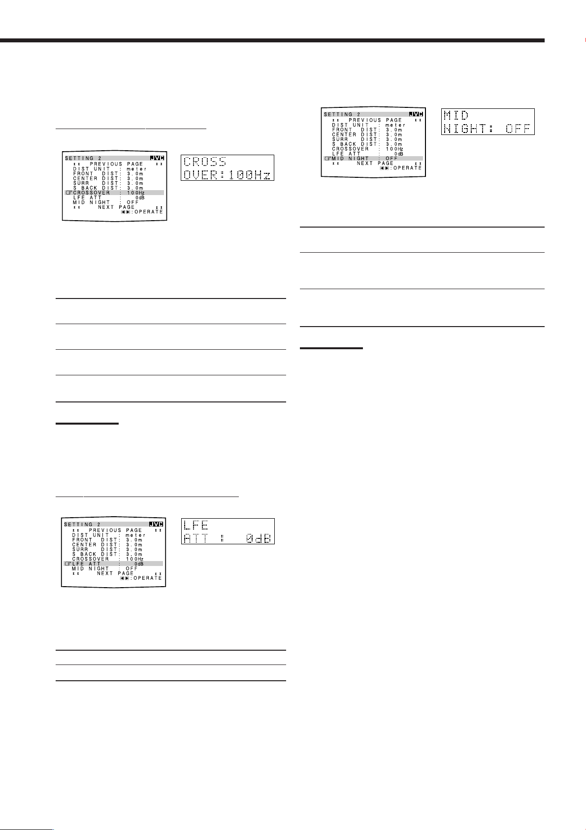
4 Setting the Bass Sounds
You can adjust subwoofer and bass sounds precisely according to
your preference.
7
Crossover frequency—CROSSOVER
[On-screen display] [Front panel]
5 Setting the Dynamic Range—MID NIGHT
[On-screen display] [Front panel]
You can enjoy a powerful sound at night using the Midnight Mode.
Select one of the following:
When you use a subwoofer, you can select the cutoff frequency
for the small speakers used.
Select one of the crossover frequency levels from “80Hz,”
“100Hz,” “120Hz” and “150Hz” according to the size of the
small speaker connected.
80Hz : Select this frequency when the cone speaker unit
built in the speaker is about 12 cm.
100Hz : Select this frequency when the cone speaker unit
built in the speaker is about 10 cm.
120Hz : Select this frequency when the cone speaker unit
built in the speaker is about 8 cm.
150Hz : Select this frequency when the cone speaker unit
built in the speaker is about 6 cm.
Notes:
• If you have selected “LARGE” for all activated speakers (see
page 22), this function is fixed to “OFF.”
• Crossover frequency is not valid for the DVD MULTI playback,
All Channel Stereo and 3D HEADPHONE mode.
7
Low frequency effect attenuator—LFE ATT
[On-screen display] [Front panel]
1:Select this when you want to reduce the dynamic range. The
MIDNIGHT MODE indicator lights up on the display.
2:Select this when you want to apply the compression effect
(useful at midnight). The MIDNIGHT MODE indicator
lights up on the display.
OFF : Select this when you want to enjoy surround with its full
dynamic range (no effect applied). The MIDNIGHT MODE
indicator goes off from the display.
Notes:
• If Analog Direct is in use, Midnight Mode is temporarily canceled.
• Midnight Mode is not valid for DVD MULTI playback mode even
though the setting is adjustable.
If the bass sound is distorted while playing back software
encoded with Dolby Digital or DTS Digital Surround, set the
LFE level to eliminate distortion.
Select one of the following:
0dB : Normally select this.
−10dB : Select this when the bass sound is distorted.
24
Page 28

6 Setting the Digital Input (DIGITAL IN)
Terminals
[On-screen display] [Front panel]
When you use the digital input terminals, you have to register which
components you have connected to the digital input terminals.
7
Digital coaxial terminal—DIGITAL 1 (DGTL COAX 1)
Set the component connected to the digital coaxial terminal
(DIGITAL IN 1)—DVD, MD**, CDR, TV (or DBS*) or CD.
*
If you have changed the source name from “TV” to “DBS,”
“DBS” appears (see page 17).
**
If you want to connect an MD recorder to the digital input
terminal, change the source name to “MD” from “TAPE” (see
page 17).
7
Digital optical terminals—DIGITAL 2, DIGITAL 3 and
DIGITAL 4
Set the components connected to the digital optical terminals
(DIGITAL IN 2 – 4).
• Each time you press 2 or 3 on the remote control or
CONTROL UP 5 or DOWN ∞ on the front panel, the digital
component names change as follows:
When “DIGITAL 1 (DGTL COAX 1)” is set to “DVD”
2: CD 3: TV (or DBS* ) 4: CDR “
2: CD 3: TV (or DBS*) 4: MD** “
2: CD 3: MD** 4: CDR “
2: MD** 3: TV (or DBS* ) 4: CDR “
(back to the beginning)
When “DIGITAL 1 (DGTL COAX 1)” is set to “MD”**
2: CD 3: TV (or DBS*) 4: CDR “
2: CD 3: TV (or DBS*) 4: DVD “
2: CD 3: DVD 4: CDR “
2: DVD 3: TV (or DBS*) 4: CDR “
(back to the beginning)
When “DIGITAL 1 (DGTL COAX 1)” is set to “CDR”
2: CD 3: TV (or DBS*) 4: DVD “
2: CD 3: TV (or DBS*) 4: MD** “
2: CD 3: MD** 4: DVD “
2: MD** 3: TV (or DBS*) 4: DVD “
(back to the beginning)
When “DIGITAL 1 (DGTL COAX 1)” is set to “CD”
2: DVD 3: TV (or DBS*) 4: CDR “
2: DVD 3: TV (or DBS*) 4: MD** “
2: DVD 3: MD** 4: CDR “
2: MD** 3: TV (or DBS*) 4: CDR “
(back to the beginning)
*
If you have changed the source name from “TV” to “DBS,”
“DBS” appears (see page 17).
**
If you want to connect an MD recorder to the digital input
terminal, change the source name to “MD” from “TAPE” (see
page 17).
Note:
When shipped from the factory, the DIGITAL IN terminals have been
set for use with the following components:
– DIGITAL 1 (coaxial): For DVD player
– DIGITAL 2 (optical): For CD player
– DIGITAL 3 (optical): For digital TV broadcast tuner
– DIGITAL 4 (optical): For CD recorder
7 Setting the Component Video Input
When you use the component video inputs for the DVD player and/
or DBS tuner, you have to register the type of input jacks.
Without setting this correctly, you cannot view the correct input on
the TV.
For the DVD player—VIDEO DVD
7
[On-screen display] [Front panel]
Select one of the following:
COMPONENT : Select this when connecting the DVD
(COMPNT) player to the component video input jacks.
S/C : Select this when connecting the DVD
player to the composite video or S-video
input jacks.
For the DBS tuner—VIDEO DBS
7
[On-screen display] [Front panel]
When “DIGITAL 1 (DGTL COAX 1)” is set to “TV” or
“DBS”*
2: CD 3: DVD 4: CDR “ 2: CD 3: DVD 4: MD** “
2: CD 3: MD** 4: CDR “ 2: MD** 3: DVD 4: CDR “
(back to the beginning)
25
Select one of the following:
COMPONENT : Select this when connecting the DBS
(COMPNT) tuner to the component video input jacks.
S/C : Select this when connecting the DBS tuner
to the composite video or S-video input
jacks.
Note:
If you have not selected appropriate video input jacks, the AV
COMPU LINK remote control system cannot operate properly.
(See page 49.)
Page 29

8 Memorizing the Volume Level for Each Source
—ONE TOUCH OPR (ONE TOUCH)
9 Showing the Text Information on the Display
—FL DISPLAY (DISP)
[On-screen display] [Front panel]
This unit memorizes some settings separately for each source (see
page 20).
In addition, you can store the volume level for each source with the
other memorized settings.
Select one of the following:
ON : Select this to store the volume level separately for each
source. (The ONE TOUCH OPERATION indicator
lights up on the display.)
This receiver memorizes the volume level—
• when you change the source
• when you change the source name.
OFF : Select this not to store the volume level.
To recall the volume level
With the ONE TOUCH OPERATION indicator lits, the volume
level for the currently selected source is recalled when the source is
selected.
[On-screen display] [Front panel]
When you have connected an MD recorder or CD player equipped
with TEXT COMPU LINK remote control system (see page 44),
you can show the text information such as disc title or track title on
the display of this receiver.
Select one of the following:
NORMAL : Source name and Surround/DSP mode appear
(NORM) during play.
TEXT : Text information appears during play.
Note:
Though you have selected “TEXT,” the source name and
Surround/DSP mode will appear while playing a disc that has no text
information.
To cancel the One Touch Operation
Set One Touch Operation to “OFF” so that the ONE TOUCH
OPERATION indicator goes off.
26
Page 30

Receiving Radio Broadcasts
ANALOG
VOLUME
TUNED STEREO
L R
SPEAKERS
1
ANALOG
VOLUME
TUNED STEREO
L R
SPEAKERS
1
You can browse through all the stations or use the preset function to go immediately to a particular station.
Tuning into Stations Manually
On the front panel:
1. Press FM/AM to select the band
(FM or AM).
The FM/AM lamp on the front panel button
lights up. The last received station of the
selected band is tuned in.
• Each time you press the button, the band
alternates between FM and AM.
L R
ANALOG
1
SPEAKERS
2. Press FM/AM TUNING 5 or ∞
until you find the frequency you
want.
• Pressing FM/AM TUNING 5 increases
the frequency.
• Pressing FM/AM TUNING ∞ decreases
the frequency.
From the remote control:
1. Press FM/AM to select the band
(FM or AM).
The FM/AM lamp on the front panel button
lights up. The last received station of the
selected band is tuned in.
• Each time you press the button, the band
alternates between FM and AM.
FM/AM
TUNED STEREO
VOLUME
FM/AM TUNING
FM / AM
Using Preset Tuning
Once a station is assigned to a channel number, the station can be
quickly tuned in. You can preset up to 30 FM and 15 AM stations.
To store the preset stations
Before you start, remember...
There is a time limit in doing the following steps. If the setting is
canceled before you finish, start from step 2 again.
On the front panel ONLY:
1. Tune in the station you want to preset (see
“Tuning into Stations Manually” on the left).
• If you want to store the FM reception mode for this station,
select the FM reception mode you want. See “Selecting the
FM Reception Mode” on page 28.
L R
ANALOG
1
SPEAKERS
2. Press MEMORY.
The channel number position starts flashing on the display for
about 10 seconds.
TUNED STEREO
VOLUME
MEMORY
2. Press TUNING UP 3 or
TUNING DOWN 2 until
you find the frequency you
/REW FF/
PAUSE
SET
DOWN – TUNING – UP
want.
• Pressing TUNING UP 3 increases the
frequency.
• Pressing TUNING DOWN 2 decreases
the frequency.
Notes:
• When a station of sufficient signal strength is tuned in, the TUNED
indicator lights up on the display.
• When an FM stereo program is received, the STEREO indicator
also lights up.
• When you hold and then release the button in step 2, the frequency
keeps changing until a station is tuned in.
3. Press FM/AM PRESET 5 or ∞ to
FM/AM PRESET
select a channel number while the
channel number position is
flashing.
L R
ANALOG
1
SPEAKERS
4. Press MEMORY again while the
TUNED STEREO
VOLUME
MEMORY
selected channel number is
flashing on the display.
The selected channel number stops flashing.
The station is assigned to the selected channel number.
5. Repeat steps 1 to 4 until you store all the stations
you want.
27
To erase a stored preset station
Storing a new station on a used number erases the previously stored
one.
Page 31
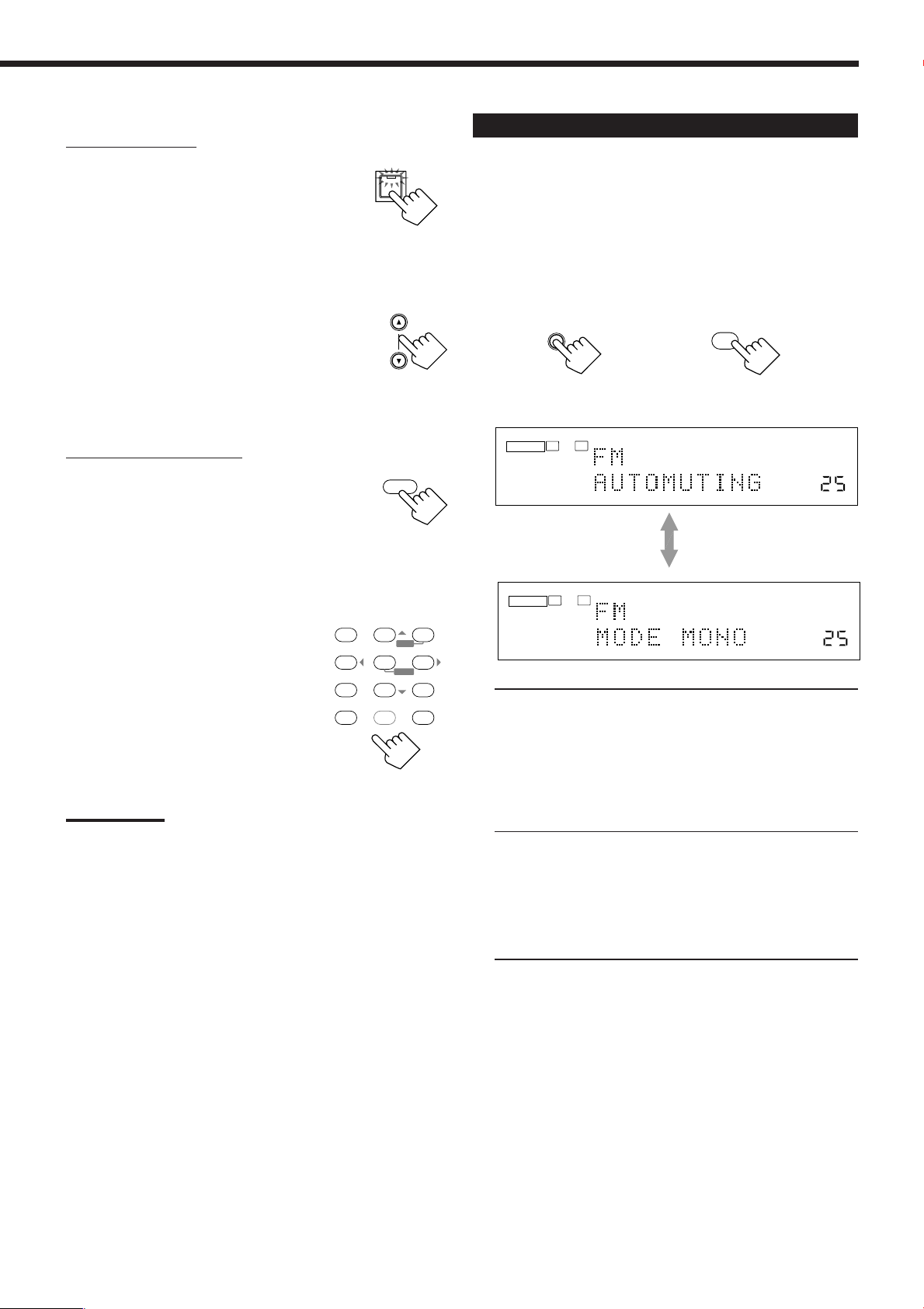
To tune in a preset station
0
∗
SBACK•L
FM MODE
On the front panel:
1. Press FM/AM to select the band
FM/AM
(FM or AM).
The FM/AM lamp on the front panel button lights
up. The last received station of the selected band is
tuned in.
• Each time you press the button, the band
alternates between FM and AM.
2. Press FM/AM PRESET 5 or ∞
FM/AM PRESET
until you find the channel you
want.
• Pressing FM/AM PRESET 5 increases the
number.
• Pressing FM/AM PRESET ∞ decreases the
number.
From the remote control:
1. Press FM/AM to select the band
FM / AM
(FM or AM).
The FM/AM lamp on the front panel button lights
up. The last received station of the selected band is
tuned in.
• Each time you press the button, the band
alternates between FM and AM.
2. Press the 10 keys to select a
preset channel number.
• For channel number 5, press 5.
• For channel number 15, press +10
then 5.
• For channel number 20, press +10
then 10.
• For channel number 30, press +10, +10,
then 10.
Note:
When you use the 10 keys on the remote control, be sure that they
are activated for the tuner, not for the CD and others. (See page 51.)
BASS
BOOST∗FRONT•L
231
CENTER
TEST
∗
564
ENTER
SURR•L∗SURR•R
∗
7/P
89
SBACK•L ∗SBACK•R
DIGITAL EQ
∗
∗
RETURN FM MODE 10 0
0
MENU
FRONT•R
∗
SUBWFR
∗
+1010
+
Selecting the FM Reception Mode
When an FM stereo broadcast is hard to receive or noisy, you can
change the FM reception mode while receiving an FM broadcast.
• You can store the FM reception mode for each preset station (see
page 27).
While listening to an FM station, press FM MODE.
• Each time you press the button, the FM reception mode alternates
between “FM AUTOMUTING” and “FM MODE MONO.”
FM MODE
On the front panel From the remote control
L R
ANALOG
SPEAKERS
1
L R
ANALOG
SPEAKERS
1
FM AUTOMUTING: Normally select this.
When a program is broadcasted in
stereo, you will hear stereo sound;
when in monaural, you will hear
monaural sounds. This mode is also
useful to suppress static noise between
stations. The AUTO MUTING indicator
lights up on the display. (Initial setting)
FM MODE MONO: Select this to improve the reception (but
stereo effect will be lost).
In this mode, you will hear noise while
tuning into the stations. The AUTO
MUTING indicator goes off from the
display. (The STEREO indicator also
goes off.)
TUNED STEREO
AUTO MUTING
VOLUME
TUNED
VOLUME
28
Page 32

Operating the Tuner Using the On-Screen
Display
You can also operate the tuner using the on-screen display.
• The on-screen display will disappear if no operation is done for
about 1 minute.
7
Operating the tuner
1. Press MENU.
The MENU screen appears on
the TV.
MENU
/REW
DOWN – TUNING – UP
On-screen operating
PLAY
PAUSE
SET
STOP
buttons
EXIT
FF/
CONTROL
2. Press 5 or ∞ to move to “TUNER CONTROL,”
then press 2 or 3.
The TUNER CONTROL menu appears.
7
Storing the preset stations
1. Press MENU.
The MENU screen appears on the TV.
2. Press 5 or ∞ to move to “TUNER CONTROL,”
then press 2 or 3.
The TUNER CONTROL menu appears.
3. Tune into a station you want to store on the
TUNER CONTROL menu, referring to
“Operating the tuner”.
4. Press 5 or ∞ to move
to “PRESET MEMORY,”
then press 2 or 3.
moves to “PRESET CH” and the channel number starts
flashing.
5. Press 2 or 3 to select a channel number you
want.
3. Press 5 or ∞ to move to an item you want to
set or adjust.
On the TUNER CONTROL menu, you can do the following:
BAND : Select the band.
PRESET CH : Select a preset channel station.
FREQUENCY : Tune in a station manually.
FM MODE : Select the FM reception mode.*
PRESET MEMORY : See “Storing the preset stations” on
the right.
Note:
*
“FM MODE” is not displayed when an AM station is selected.
4. Press 2 or 3 to select an item you want to use.
5. When you finish, press EXIT repeatedly until the
menu disappears from the TV.
6. Press SET to store the setting.
The selected channel number stops flashing.
7. Repeat steps 3 to 6 until you store all the stations
you want.
8. When you finish, press EXIT repeatedly until the
menu disappears from the TV.
29
Page 33

Setting Sound
DIRECT
ANALOG
You can select the following sound settings to your preference according to your listening conditions or sources.
• Items shown in this section are the initial values when shipped from the factory.
• The on-screen display will disappear if no operation is done for about 1 minute.
Attenuating the Input Signal
When the input level of the analog source is too high, the sounds
will be distorted. If this happens, you need to attenuate the input
signal level to prevent the sound distortion.
• Once you have made adjustment, it is memorized for each source.
On the front panel:
Press and hold INPUT ATT (INPUT
INPUT
ANALOG/DIGITAL
ANALOG/DIGITAL) so that the
INPUT ATT indicator lights up on the
INPUT ATT
display.
• Each time you press and hold the button, the
input attenuator mode turns on (“ATT ON”) or
off (“NORMAL”).
Using the on-screen display (through the remote control]:
1. Press MENU.
/REW
PLAY
PAUSE
SET
STOP
buttons
EXIT
FF/
CONTROL
The MENU screen appears on
the TV.
MENU
DOWN – TUNING – UP
On-screen operating
Turning Analog Direct On and Off
You can enjoy the sound closer to the original source by overriding
the sound adjustments such as speaker output level adjustments (see
page 40), Equalization pattern (see page 39), Surround and DSP
modes (see pages 32 to 36), Bass Boost (see page 31) and Midnight
Mode (see page 24). You can only adjust the volume level while
Analog Direct is in use.
• Once you have made adjustment, it is memorized for each source.
Press ANALOG DIRECT to turn on Analog Direct.
The ANALOG DIRECT lamp on the front panel button lights up.
• Each time you press the button, Analog Direct turns on and off.
– When Analog Direct turns on, “A. DIRECT” appears on the
display.
ANALOG DIRECT
On the front panel
From the remote control
Using the on-screen display (through the remote control]:
1. Press MENU.
The MENU screen appears on the TV.
2. Press 5 or ∞ to move to “SOUND CONTROL,”
then press 2 or 3.
The SOUND CONTROL menu appears.
2. Press 5 or ∞ to move to “SOUND CONTROL,”
then press 2 or 3.
The SOUND CONTROL menu appears.
3. Press 5 or ∞ to move to “INPUT ATT.”
4. Press 2 or 3 to select “ATT ON” or
“NORMAL.”
When “ATT ON” is selected, the INPUT ATT indicator lights up
on the display.
5. When you finish, press EXIT repeatedly until the
menu disappears from the TV.
Notes:
• This function is available when analog input terminals are in use.
• This function is not valid for the DVD MULTI playback mode.
3. Press 5 or ∞ to move to “ANALOG
DIRECT.”
4. Press 2 or 3 to select “ON” or “OFF.”
When Analog Direct is turned on, the ANALOG DIRECT lamp
on the front panel button lights up.
– When Analog Direct turns on, “A. DIRECT” appears on the
display.
5. When you finish, press EXIT repeatedly until the
menu disappears from the TV.
Notes:
• When digital input mode is in use, Analog Direct is not available.
• Turning on Surround or DSP mode cancels Analog Direct and
previously selected sound adjustments are recalled.
• If Analog Direct is in use, Midnight Mode is temporarily canceled
even though adjustable.
30
Page 34

Reinforcing the Bass
SUBWOOFER OUT ON/OFF
You can boost the bass level.
• Once you have made adjustment, it is memorized for each source.
On the front panel:
Press BASS BOOST to turn on Bass
BASS BOOST
Boost function.
The BASS BOOST lamp on the front panel button
lights up.
• Each time you press the button, Bass Boost
activates (“BOOST ON”) and deactivates
(“BOOST OFF”) alternately.
From the remote control:
PLAY
PAUSE
SET
STOP
buttons
SOUND
BASS
BOOST
1
EXIT
FF/
CONTROL
1. Press SOUND.
The 10 keys are activated for sound
adjustments.
2. Press BASS BOOST to turn on Bass
Boost function.
The BASS BOOST lamp on the front panel
button lights up.
• Each time you press the button, Bass Boost activates
(“BOOST ON”) and deactivates (“BOOST OFF”) alternately.
Using the on-screen display (through the remote control]:
1. Press MENU.
The MENU screen appears on
the TV.
MENU
/REW
DOWN – TUNING – UP
On-screen operating
Notes:
• This function does not affect the sounds outputting from the
surround speakers.
• When Analog Direct is in use (see page 30), the Bass Boost
function is canceled temporarily.
Activating the Subwoofer Sound
You can cancel the subwoofer sound even though you have
connected a subwoofer and have set “SUBWOOFER” to “YES”
(see page 22). This is useful when enjoying surround sound at night.
On the front panel:
Press SUBWOOFER OUT ON/OFF
to cancel the subwoofer sound
output.
Each time you press the button, the subwoofer sound output is
deactivated (“SUBWFR OFF”) and activated (“SUBWFR ON”)
alternately.
Using the on-screen display (through the remote control]:
1. Press MENU.
The MENU screen appears on the TV.
2. Press 5 or ∞ to move to “SOUND
CONTROL,” then press 2 or 3.
The SOUND CONTROL menu appears.
3. Press 5 or ∞ to move to “SUBWOOFER.”
2. Press 5 or ∞ to move to “SOUND CONTROL,”
then press 2 or 3.
The SOUND CONTROL menu appears.
3. Press 5 or ∞ to move to “BASS BOOST.”
4. Press 2 or 3 to select “ON” or “OFF.”
When Bass Boost is turned on, the BASS BOOST lamp on the
front panel button lights up.
5. When you finish, press EXIT repeatedly until the
menu disappears from the TV.
31
4. Press 2 or 3 to select “ON” or “OFF.”
5. When you finish, press EXIT repeatedly until the
menu disappears from the TV.
Notes:
• If you have selected “NO” for the subwoofer (see page 22), you
cannot use this function.
• When you have selected “SMALL” for the front speakers, you
cannot select “OFF” for the subwoofer even if it is set to “YES” (see
page 22).
Page 35

Using Surround Modes and DSP Modes
DIGITAL
This unit activates a variety of Surround modes and DSP (Digital Signal Processor) modes. To use Surround and DSP
modes properly, speakers required for creating each Surround and DSP modes should be activated.
■ Surround Modes
Reproducing Theater Ambience
In a movie theater, many speakers are located on the walls to
reproduce impressive multi-surround sounds, reaching you from all
directions.
With these many speakers, sound localization and sound movement
can be expressed.
Surround modes built in this receiver can create almost the same
surround sounds as you can feel in a real movie theater.
Movie theater
At home
Center speaker
Subwoofer
Left front speaker(s)
Right front speaker(s)
Introducing the Surround Modes
■ Dolby Surround
Dolby Digital EX*
Dolby Digital EX is newly introduced surround encoding format as
an extension of multi-channel Dolby Digital, designed to add an
extra surround channel to Dolby Digital 5.1-channel (see below). By
using a matrix encoding/decoding method, additional “surround
back” channel signal is encoded (and decoded) in both the left and
right surround channel signals.
Compared to the conventional Dolby Digital 5.1-channel, this newly
added surround back channel can reproduce more detailed
movements behind you while viewing the video software. In
addition, surround sound localization will become more stable, so
that you can enjoy a realistic surround field in your listening room.
Best used to reproduce multi-channel movie sound tracks of the
software encoded with Dolby Digital EX (
• To enjoy the software encoded with Dolby Digital EX, connect the
source component using the digital terminals on the rear of this
receiver. (See page 13.)
Dolby Digital*
Used to reproduce multi-channel sound tracks of the software
encoded with Dolby Digital (
Dolby Digital 5.1-channel encoding method (so-called discrete
5.1-channel digital audio format) records and digitally compresses
the left front channel, right front channel, center channel, left
surround channel, right surround channel, and LFE channel signals
(total 6 channels, but LFE channel is counted as 0.1 channel,
therefore, called 5.1-channel).
Since each channel is completely independent from the other
channel signals to avoid interference, you can obtain a much better
sound quality with better stereo and surround effects.
• To enjoy the software encoded with Dolby Digital, connect the
source component using the digital terminals on the rear of this
receiver. (See page 13.)
* Dolby Digital software can be roughly grouped into two categories
—multi-channel (up to 5.1-channel) and 2-channel software. To
enjoy surround sounds while playing Dolby Digital 2-channel
software, you can use Dolby Pro Logic II.
).
).
Left surround speakerLeft surround speaker
Surround back speaker(s)
Right surround speaker
Dolby Pro Logic II*
Dolby Pro Logic II has a newly developed multi-channel playback
format to convert all 2-channel software into 5-channel (plus subwoofer).
Matrix-based conversion method for Dolby Pro Logic II makes no
limitation for the cutoff frequency of the surround treble and enables
stereo surround sound unavailable with conventional Dolby Pro Logic.
Dolby Pro Logic II can reproduce spacious sound from original
sound without adding any new sounds and tonal colorations.
Dolby Pro Logic II has two modes—Movie mode and Music mode:
Pro Logic II Movie (PL II MOVIE)—suitable for the reproduction
of Dolby Surround encoded sources bearing the mark
You can enjoy a sound field very close to the one created with
discrete 5.1-channel sounds.
Pro Logic II Music (PL II MUSIC)—suitable for the reproduction
of any 2-channel stereo sources. You can enjoy wide and deep sound
by using this mode. For this mode, you can make precise
adjustments to match the sound to your taste.
• When Dolby Pro Logic II is activated, the
indicator lights up on the display.
PRO LOGIC II
DOLBY SURROUND
32
.
Page 36

Dolby Surround (Dolby Pro Logic)*
Used to reproduce sound tracks of the software encoded with Dolby
Surround (
DOLBY SURROUND
).
Dolby Surround encoding format records the left front channel,
right front channel, center channel, and surround channel signals
(total 4 channels) into 2 channels.
The Dolby Pro Logic decoder built in this receiver decodes these
2-channel signals into original 4-channel signals—matrix-based
multi-channel reproduction, and allows you to enjoy a realistic
surround sound in your listening room.
• When Dolby Pro Logic is activated, the
PRO LOGIC indicator
lights up on the display.
DTS Digital Surround**
Used to reproduce multi-channel sound tracks of the software
encoded with DTS Digital Surround (
).
DTS Digital Surround is a discrete 5.1-channel digital audio
format available on CD, LD, and DVD software.
Compared to Dolby Digital, DTS Digital Surround format has a
lower audio compression ratio which enables it to add breadth and
depth to the sounds reproduced. As such, DTS Digital Surround
features natural, solid and clear sound.
• To enjoy the software encoded with DTS Digital Surround,
connect the source component using the digital terminals on the
rear of this receiver. (See page 13.)
■ DTS Digital Surround
DTS-ES Extended Surround (DTS-ES)**
DTS-ES Extended Surround is another new digital surround
encoding format, developed by Digital Theater Systems, Inc., that
adds the third surround channel—surround back channel. (See
“Dolby Digital EX.”)
DTS ES has two types—DTS-ES Discrete 6.1 and DTS-ES Matrix 6.1:
DTS-ES Discrete 6.1—compatible with DTS-ES Extended
Surround (DTS-ES), which has discrete 6.1-channel. You can play
back the software encoded with DTS ES (
DTS-ES Matrix 6.1—is designed to add an extra surround channel
to DTS Digital Surround 5.1-channel. By using a matrix encoding/
decoding method, additional “surround back” channel signal is
encoded (and decoded) in both the left and right surround channel
signals. You can playback the software encoded with DTS-ES
(
).
• To enjoy the software encoded with DTS-ES, connect the source
component using the digital terminal on the rear of this receiver.
(See page 13.)
Neo:6**
Neo:6 is a newly developed conversion method to create
6-channel (plus subwoofer) from all 2-channel software. Neo:6 has
two modes—Neo:6 Cinema and Neo:6 Music:
Neo:6 Cinema—suitable for reproduction of matrix-based 2-channel
software.
Neo:6 Music—suitable for reproduction of all 2-channel stereo
music software.
).
When using Surround mode, the sounds come out of all the
connected and activated speakers.
• If only the front speakers are connected, JVC’s original
3D-PHONIC processing (which has been developed to create the
surround effect only through the front speakers) is used.
The 3D-PHONIC indicator lights up on the display.
DVD MULTI Playback Mode
This receiver provides the DVD MULTI playback mode for
reproducing the analog discrete 5.1-channel output mode of the
DVD player.
You can adjust the sound reproduced by DVD MULTI playback
mode while playing back video software such as a DVD using
the analog discrete 5.1-channel output mode.
• For the connection and the details of the DVD MULTI
playback mode, see page 37.
Note:
When you select “DVD MULTI” as the source to play, you cannot
select any Surround and DSP modes.
*
Manufactured under license from Dolby Laboratories. “Dolby,” “Pro
Logic,” and the double-D symbol are trademarks of Dolby
Laboratories.
**
“DTS,” “DTS-ES Extended Surround” and “Neo:6” are trademarks
of Digital Theater Systems, Inc.
Reproduced software and channels for each Surround mode
Surround
mode
Playback
software 2-channel stereo software 2-channel stereo software
Reproduced
channels
Surround
mode
Playback DTS-ES DTS-ES
software
Reproduced
channels
Dolby Digital EX Dolby Digital 5.1-channel Dolby Pro Logic II Dolby Surround
Dolby Digital EX Dolby Digital 5.1-channel
Dolby Digital 2-channel Dolby Surround
6.1-channel 5.1-channel 5-channel + (subwoofer) 4-channel + (subwoofer)
DTS-ES Discrete 6.1 DTS-ES Matrix 6.1
Neo:6 Cinema
DTS Digital Surround
Neo:6 Music
(with Discrete
signals) signals)
6.1-channel 6.1-channel
-channel (with Matrix 6.1-channel
6.1
2-channel stereo software DTS Digital Surround
6-channel + (subwoofer)
5.1-channel
33
Page 37

■ DSP Modes
DAP (Digital Acoustic Processor) modes
The sound heard in a concert hall, club, etc. consists of direct sound
and indirect sound—early reflections and reflections from behind.
Direct sounds reach the listener directly without any reflection. On
the other hand, indirect sounds are delayed by the distances of the
ceiling and walls (see the diagram below). These indirect sounds are
the most important elements of the acoustic surround effects.
The DAP mode can reproduce a realistic sound field by adding these
indirect sounds.
Reflections from
Early reflections
Direct sounds
behind
All Channel Stereo mode (ALL STEREO)
This mode can reproduce a larger stereo sound field using all the
connected (and activated) speakers.
All Channel Stereo can be used when the front and surround
speakers are connected to this receiver without respect to the
center and/or surround back speakers connection.
Sound reproduced from normal stereo
You can use the following DAP modes in order to reproduce a more
acoustic sound field in your listening room.
HALL 1: Gives clear vocal and the feeling of a large concert
hall (where the seating capacity is about 1,000).
HALL 2: Gives clear vocal and the feeling of a small concert
hall (where the seating capacity is about 300).
LIVE CLUB: Gives the feeling of a live music club with a low
ceiling.
DANCE CLUB: Gives a throbbing bass beat.
PAVILION: Gives the spacious feeling of a pavilion with a
high ceiling.
JVC Theater Surround
In order to reproduce a more realistic sound field in your listening
room, you can use JVC Theater Surround.
THEATER 1: Reproduces the sound field of a large theater
(where the seating capacity is about 1,000).
THEATER 2: Reproduces the sound field of a small theater
(where the seating capacity is about 300).
When using DAP mode or JVC Theater Surround, the sounds
come out of all the connected and activated speakers.
• If only the front speakers are connected or the front and
center speakers are connected, JVC’s original 3D-PHONIC
processing (which has been developed to create the surround
effect only through the front speakers) is used.
The 3D-PHONIC indicator lights up on the display.
Sound reproduced from All Channel Stereo mode
3D HEADPHONE Mode
This receiver creates acoustic environment through the
headphones as though using 5 speakers by signal processing
algorithms—3D HEADPHONE mode. The processor combines
all channels except LFE channel into two encoded channels.
By turning off both the SPEAKERS ON/OFF 1 and
SPEAKERS ON/OFF 2 then pressing DSP, 3D HEADPHONE
mode is activated without respect to the type of software played
back. You can enjoy more natural sound as though you are
listening to directly through the conventional stereo headphones.
The DSP and HEADPHONE indicators also light up.
34
Page 38

Available Surround and DSP Modes According to the Speaker Layouts
Available Surround and DSP modes will vary depending on how many speakers are used with this receiver.
Make sure that you have set the speaker setting correctly (see page 22).
• To turn on and select Surround and DSP modes, see page 36.
Speaker layouts
6 or 7 speakers
Front
speaker
Surround
speaker
Surround
back
speaker
* When selecting “1SPK” for the surround
back speaker setting (see page 22).
TV
Center speaker
Surround
back
speaker*
Front
speaker
Surround
speaker
Surround
back
speaker
5 speakers
Front
speaker
Surround
speaker
TV
Center speaker
Front
speaker
Surround
speaker
Dolby Digital EX software : DOLBY D EX*
Dolby Digital 5.1-channel software
DTS-ES software : ES DSCRETE*
DTS 5.1-channel software : DTS*
2-channel software : PL II MOVIE, PL II MUSIC
Dolby Digital EX software : DOLBY D
Dolby Digital 5.1-channel software
DTS-ES software : DTS
DTS 5.1-channel software : DTS
2-channel software : PL II MOVIE, PL II MUSIC
Available Surround modes
: DOLBY D*
: DOLBY D EX**
ES MATRIX*
: DTS NEO:6**
PRO LOGIC, NEO:6CINMA
NEO:6MUSIC
: DOLBY D
PRO LOGIC, NEO:6CINMA
NEO:6MUSIC
Available DSP modes
THEATER 1
THEATER 2
HALL 1
HALL 2
LIVE CLUB
DANCE CLUB
PAVILION
ALL STEREO
THEATER 1
THEATER 2
HALL 1
HALL 2
LIVE CLUB
DANCE CLUB
PAVILION
ALL STEREO
4 speakers
Front
speaker
Surround
speaker
3 speakers
Front
speaker
2 speakers
Front
speaker
TV
TV
Center speaker
TV
TV
Front
speaker
Surround
speaker
Front
speaker
Front
speaker
Dolby Digital EX software : DOLBY D
Dolby Digital 5.1-channel software
: DOLBY D
DTS-ES software : DTS
DTS 5.1-channel software : DTS
2-channel software : PL II MOVIE, PL II MUSIC
PRO LOGIC, NEO:6CINMA
NEO:6MUSIC
Dolby Digital EX software : DOLBY D
Dolby Digital 5.1-channel software
: DOLBY D
DTS-ES software : DTS
DTS 5.1-channel software : DTS
2-channel software : PL II MOVIE, PL II MUSIC
PRO LOGIC, NEO:6CINMA
NEO:6MUSIC
Dolby Digital EX software : DOLBY D
Dolby Digital 5.1-channel software
: DOLBY D
DTS-ES software : DTS
DTS 5.1-channel software : DTS
2-channel software : PL II MOVIE, PL II MUSIC
THEATER 1
THEATER 2
HALL 1
HALL 2
LIVE CLUB
DANCE CLUB
PAVILION
ALL STEREO
THEATER 1
THEATER 2
HALL 1
HALL 2
LIVE CLUB
DANCE CLUB
PAVILION
THEATER 1
THEATER 2
HALL 1
HALL 2
LIVE CLUB
DANCE CLUB
PAVILION
3D H.PHONE
Notes:
*
You can select these modes by setting “EX/ES” to “AUTO” (initial setting) when the surround back speakers are set to “LARGE” or “SMALL” (see
pages 22 and 23).
**
You can select these modes by setting “EX/ES” to “ON” when the surround back speakers are set to “LARGE” or “SMALL” (see pages 22 and 23).
35
Page 39
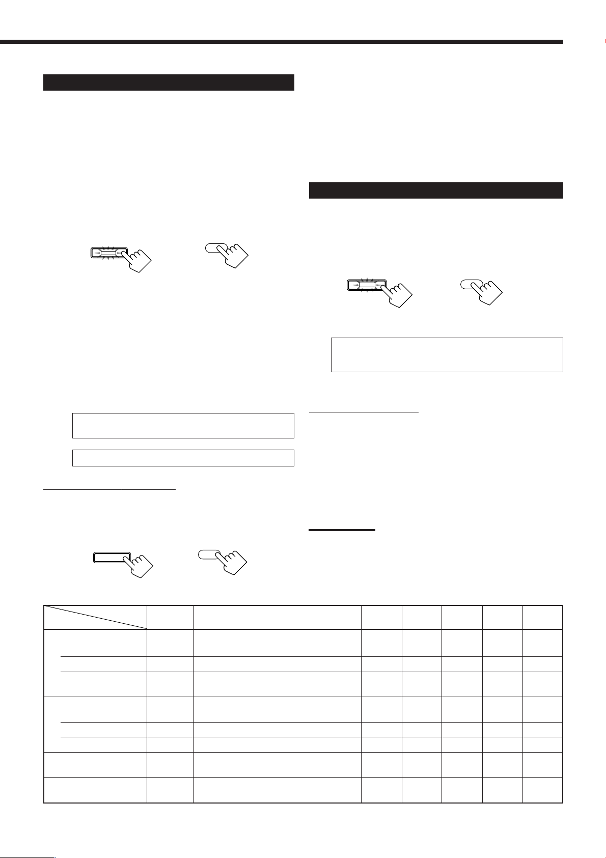
Activating the Surround Modes
DSP
DSP
Available Surround modes will vary depending on how many
speakers are used with this receiver.
Make sure that you have set the speaker setting correctly (see
page 22).
1. Set the analog or digital input mode for the
source you like to use and start playing.
When playing back multi-channel digital software, select the
digital input mode (see page 19).
• If Surround mode is canceled while playing back multi-channel
digital software, all channel signals are mixed and output through
the front speakers (and subwoofer if you have connected a
subwoofer and set its setting correctly—“YES”).
You can also adjust digital equalization patterns,
speaker output levels and some sound parameters.
See “Adjusting Sound” on pages 38 to 42 for details.
Activating the DSP Modes
2. Press SURROUND to activate Surround mode.
• The SURROUND lamp on the front panel button lights up.
SURROUND
On the front panel
• When playing back multi-channel digital software, an
appropriate Surround mode will be selected according to your
setting. See “2 Selecting Channel Numbers to Reproduce
Multi-channel Digital Software” on page 23 for details.
When selecting “AUTO” (initial setting) for “EX/ES” setting,
Surround modes shown on page 35 are activated.
• If you are playing back any other software—analog, Linear
PCM, Dolby Digital 2-channel—the last selected Surround
mode is activated. Each time you press the button, Surround
mode changes as follow:
• More than 3 speakers*
PL II MOVIE = PL II MUSIC = PRO LOGIC
NEO:6CINMA = NEO:6MUSIC = (Back to the beginning)
• 2 speakers*
PL II MOVIE
*
See also speaker layouts on page 35.
“
PL II MUSIC
To cancel the Surround mode
Press SURROUND/DSP OFF on the front panel or SURR/DSP
OFF on the remote control so that “SURR OFF” appears on the
display. Surround and DSP modes are deactivated. The
SURROUND lamp on the front panel button goes off.
SURROUND/DSP
OFF
SURROUND
From the remote control
=
SURR/DSP
OFF
1. Select and play any sound source.
2. Press DSP to activate DSP mode.
The last selected DSP mode is activated.
• The DSP lamp on the front panel button lights up.
On the front panel
• Each time you press the button, DSP mode changes as follow:
THEATER 1 = THEATER 2 = HALL 1 = HALL 2
LIVE CLUB = DANCE CLUB = PAVILION
ALL STEREO* =(Back to the beginning)
*
“ALL STEREO” can be selected when the surround speakers
are set to “LARGE” or “SMALL” (see page 22).
To cancel the DSP mode
Press SURROUND/DSP OFF on the front panel or SURR/DSP OFF
on the remote control so that “SURR OFF” appears on the display.
DSP and Surround modes are deactivated. The DSP lamp on the
front panel button goes off.
You can also adjust digital equalization patterns,
speaker output levels and some sound parameters.
See “Adjusting Sound” on pages 38 to 42 for details.
Note:
If Analog Direct is turned on when using analog input mode (see
pages 19 and 30), currently selected Surround and/or DSP mode is
canceled temporarily.
From the remote control
=
=
On the front panel
From the remote control
Available Surround and DSP modes for each input signal
Mode Surround
䡬 Dolby D EX 䡬䡬䡬䡬䡬
䡬 (DTS-) ES DSCRETE, DTS 䡬䡬䡬䡬䡬
䡬 (DTS-) ES MATRIX, DTS 䡬䡬䡬䡬䡬
䡬
䡬
PL II MOVIE, PL II MUSIC, PRO LOGIC,
NEO:6CINMA, NEO:6MUSIC
PL II MOVIE, PL II MUSIC, PRO LOGIC,
NEO:6CINMA, NEO:6MUSIC
PL II MOVIE, PL II MUSIC, PRO LOGIC,
NEO:6CINMA, NEO:6MUSIC
Signals off (stereo)
Dolby Digital
EX (6.1-channel)
(5.1-channel) 䡬 Dolby D, Dolby D EX* 䡬䡬䡬䡬䡬
(2-channel) 䡬
DTS Digital Surround
ES Discrete (6.1-channel)
ES Matrix (6.1-channel)
(5.1-channel) 䡬 DTS, DTS NEO:6* 䡬䡬䡬䡬䡬
Linear PCM
Analog
*
You can select these modes by setting “EX/ES” to “ON” when the surround back speakers are set to “LARGE” or “SMALL” (see pages 22 and 23).
Available Surround mode
DAP JVC Theater All Channel
modes Surround Stereo headphon
䡬䡬䡬䡬䡬
䡬䡬䡬䡬䡬
䡬䡬䡬䡬䡬
Headphone
3D
e
36
Page 40

Using the DVD MULTI Playback Mode
This receiver provides the DVD MULTI playback mode for reproducing the analog discrete output mode of the DVD
player. Before playing back a DVD, refer also to the manual supplied with the DVD player.
When using DVD MULTI playback mode, connect the DVD player with its analog discrete output jacks (Å – ‰).
DVD
SUB
WOOFER
CENTER
RIGHT
B
AUDIO
SURR
(REAR)
PHONO
CD
OUT
(REC)
TAPE
MD
IN
(PLAY)
OUT
(REC)
CDR
IN
(PLAY)
C
RIGHT
A
LEFT
DVD player
D
LEFT
FRONT
TV SOUND
DVD
E
DVD
DBS
OUT
(REC)
VCR1
IN
(PLAY)
OUT
(REC)
VCR2
IN
(PLAY)
MONITOR
OUT
VIDEO
G
F
DVD
DBS
MONITOR
OUT
COMPONENT VIDEO
B/CB
P
Y
PR/CR
S-VIDEOVIDEO
Å To surround left/right audio output
ı To center audio output
Ç To subwoofer output
Î To front left/right audio output
‰ To composite video output
Ï To S-video output
Ì To component video output
Activating the DVD MULTI Playback Mode
1. Press DVD MULTI so that “DVD MULTI”
appears on the display.
The DVD MULTI lamp on the front panel button and the DVD
MULTI indicator light up.
DVD MULTI
On the front panel
Note:
When you select “DVD MULTI” as the source to play, the
Surround and DSP modes are canceled, and the SURROUND
and DSP buttons do not work.
DVD MULTI
From the remote control
2. Select the analog discrete output mode on the
DVD player, and start playing a DVD.
• Refer also to the manual supplied with the DVD player.
You can also adjust digital equalization patterns and
speaker output levels. See “Adjusting Sound” on
pages 38 to 41 for details.
• Test tone does not output through the speakers to adjust the
speakers output levels when selecting DVD MULTI.
Notes:
• Midnight Mode is not available for DVD MULTI playback mode (see
page 24).
• When using a pair of headphones, the sounds of front left and right
channels are output from the headphones.
37
Page 41

Adjusting Sound
You can adjust sound parameters to your preference after completing basic setting.
• When performing the sound adjustments, it is recommended to use the TV screen so that you can show the
on-screen display on the TV.
• When using the buttons on the front panel or remote control without using the on-screen display, you can perform
the same adjustments. (The on-screen display cannot be shown.)
• The on-screen display will disappear if no operation is done for about 1 minute.
Basic Procedure
You can also adjust the sound without showing menus on the TV. For details, see each explanation that follows.
Using the on-screen display (through the remote control]:
1. Press MENU.
The MENU screen appears on the TV.
MENU
PLAY
EXIT
/REW
DOWN – TUNING – UP
On-screen operating buttons
PAUSE
SET
STOP
FF/
CONTROL
2. Press 5 or ∞ to move to “SOUND CONTROL,” then press 2 or 3.
The SOUND CONTROL menu appears.
3. Press 5 or ∞ to move to select “DIGITAL EQ (Equalization),” “LEVEL ADJUST” or “EFFECT
ADJUST,” then press 2 or 3.
4. Press 5 or ∞ to move
SOUND CONTROL menu
to an item you want to set.
DIGITAL EQ (Equalization) menu
(see page 39)
LEVEL ADJUST menu (see page 40)
EFFECT ADJUST menu (see page 42)
5. Press 2 or 3 to adjust a sound parameter.
6. When you finish, press EXIT repeatedly until the menu disappears from the TV.
• If Analog Direct is in use, you cannot make any sound adjustments.
• Above items shown on the on-screen display are initial values when shipped from the factory.
• Some of the items cannot be shown or cannot be adjusted. (For details, see the respective explanation in this section.)
38
Page 42

EQ 63Hz EQ250Hz
EQ 1kHz
EQ 4kHzEQ16kHz
and its level
and its level
and its level
and its level
and its level
Adjusting the Equalization Patterns
U
—DIGITAL EQ
You can adjust the equalization patterns to your preference.
• Once you have made adjustment, it is memorized for each source.
Using the on-screen display (through the remote control]:
1. Show DIGITAL EQ (Equalization) menu (see
page 38).
2. Press 5 or ∞ to move
to the frequency you
want to adjust.
3. Press 2 or 3 to adjust the frequency level you
want.
The DIGITAL EQ indicator lights up on the display.
• The frequency level changes from –8 dB to +8 dB in 2 dB
steps.
2. Press CONTROL UP 5 or
CONTROL
DOWN UP
DOWN ∞ repeatedly to adjust the
frequency level.
The DIGITAL EQ indicator lights up on the
display.
• The frequency level changes from –8 dB to
+8 dB in 2 dB steps.
3. Repeat steps 1 and 2 to adjust the other
frequency levels.
To flat the equalization pattern,
set all the frequency levels to “0dB” in step 2. The DIGITAL EQ
indicator goes off from the display.
From the remote control:
Before you start, remember...
There is a time limit in doing the following steps. If the setting is
canceled before you finish, start from step 2 again.
1. Press SOUND.
“SOUND” appears on the remote control display
window.
• The 10 keys are activated for sound adjustments.
SOUND
4. Repeat steps 2 and 3 to adjust the other
frequency levels.
5. When you finish, press EXIT repeatedly until the
menu disappears from the TV.
To flat the equalization pattern,
set all the frequency levels to “0dB” in step 3. The DIGITAL EQ
indicator goes off from the display.
On the front panel:
Before you start, remember...
There is a time limit in doing the following steps. If the setting is
canceled before you finish, start from step 1 again.
1. Press DIGITAL EQ (Equalization)
DIGITALEQLEV
ADJ
repeatedly to select the frequency you
want to adjust.
• Each time you press the button, the frequency
with its current level changes as follows:
EQ 63Hz EQ250Hz
and its level
•“0dB” is the initial setting for each frequency.
and its level
and its level
EQ 1kHz
and its level
EQ 4kHzEQ16kHz
and its level
DIGITAL EQ
2. Press DIGITAL EQ (Equalization)
repeatedly to select the frequency you
∗
10
RETURN
want to adjust.
“EQ” appears on the remote control display window.
• Each time you press the button, the frequency with its current
level changes as follows:
•“0dB” is the initial setting for each frequency.
3. Press LEVEL + or − repeatedly
to adjust the frequency level.
The DIGITAL EQ indicator lights up on
the display.
• The frequency level changes from
–8 dB to +8 dB in 2 dB steps.
+
CH/∗LEVEL
−
4. Repeat steps 2 and 3 to adjust the other
frequency levels.
To flat the equalization pattern,
set all the frequency levels to “0dB” in step 3. The DIGITAL EQ
indicator goes off from the display.
39
Notes:
• When Analog Direct is in use, the digital equalization patterns
cannot be adjusted.
• The digital equalization patterns affect the front speaker sounds
only.
Page 43
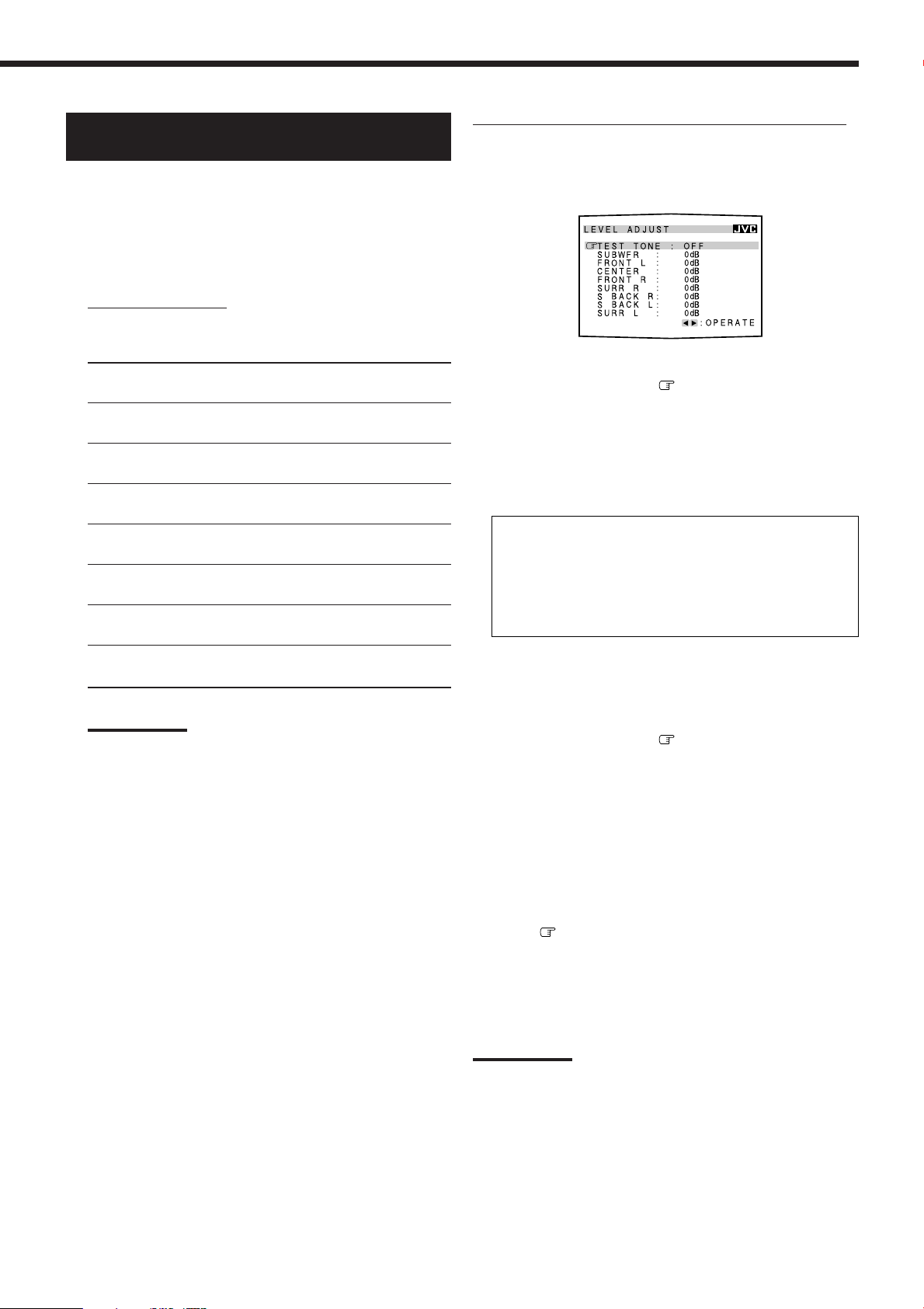
Adjusting the Speaker Output Levels
—LEVEL ADJUST
Using the on-screen display (through the remote control]:
Adjustment is also possible without outputting the test tone. In this
case, you can skip steps 2, 3 and 7 below.
You can adjust the speaker output levels. The test tone can be also
output from each speaker except subwoofer to check the output level
balance when using the Surround mode.
• Once you have made adjustment, it is memorized for each source.
• When using the buttons on the front panel to adjust output level
for the Surround mode, no test tone is available.
7
Adjustable speakers
You can adjust the following speakers’ output levels within the
range of –10 dB to +10 dB (“0 dB” is the initial setting):
SUBWFR :
FRONT L (FRNT L) :
CENTER :
FRONT R (FRNT R):
SURR R :
S BACK R (SBK R) *:
S BACK L (SBK L) :
or S BACK*
SURR L :
Select this to adjust the subwoofer
output level.
Select this to adjust the left front
speaker output level.
Select this to adjust the center
speaker output level.
Select this to adjust the right front
speaker output level.
Select this to adjust the right
surround speaker output level.
Select this to adjust the right
surround back speaker output level.
Select this to adjust the left surround
back speaker output level.
Select this to adjust the left surround
speaker output level.
Notes:
*
If you have selected “1SPK” for the surround back speaker (see
page 22), “S BACK” appears instead of “S BACK (SBK) L” and
“S BACK (SBK) R.” No test tone outputs from the right surround
back speaker.
• If you have selected “NO” or “NONE” for a speaker (see page
22), the output level for the corresponding speaker cannot be
adjustable.
• The center and left and right surround speakers’ output levels
are adjustable for DVD MULTI playback mode, even though
“NONE” is selected for the speaker settings.
• Speaker output levels except that of the subwoofer are not
adjustable when Analog Direct is in use.
1. Show LEVEL ADJUST menu (see page 38).
2. Press 5 or ∞ to move
3. Press 2 or 3 to select “ON”
to “TEST TONE.”
to check if you can
hear the sounds through all the speakers at equal
level.
A test tone comes out of the speakers (only if the speakers are
activated) in the following order:
FRONT L (Left front speaker) = CENTER (Center speaker)
FRONT R (Right front speaker)
SURR R (Right surround speaker)
S BACK R (Right surround back speaker)
S BACK L (Left surround back speaker) or
S BACK (Surround back speaker)
SURR L (Left surround speaker) = (Back to the beginning)
*
If you have selected “1SPK” for the surround back speaker (see
page 22), “S BACK” appears instead of “S BACK L” and
“S BACK R.” No test tone outputs from the right surround back
speaker.
* =
=
=
* =
=
4. Press 5 or ∞ to move to a speaker you want
to adjust.
5. Press 2 or 3 to adjust the speaker output level
(–10 dB to +10 dB).
6. Repeat steps 4 and 5 to adjust the other speakers
output levels.
7. After the adjustment is finished, press 5 or ∞ to
move
to “TEST TONE,” then select “OFF.”
8. When you finish, press EXIT repeatedly until the
menu disappears from the TV.
Notes:
• If you have selected “NO” or “NONE” for a speaker (see page 22),
test tone does not come out of the corresponding speaker.
• Subwoofer output level cannot be adjusted when outputting test
tone. When you adjust the subwoofer output level, select “OFF” for
“TEST TONE.”
• Test tone does not output through the speakers when selecting
DVD MULTI.
40
Page 44

From the remote control:
Before you start, remember...
There is a time limit in doing the following steps. If the setting is
canceled before you finish, start from step 2 again.
Adjustment is also possible without outputting the test tone. In this
case, you can skip steps 2 and 6 below.
5. Press SOUND again then repeat steps 3
and 4 to adjust the other speakers
output levels.
6. Press TEST again to stop the test
tone.
SOUND
TEST
4
MENU
1. Press SOUND.
“SOUND” appears on the remote control display
window.
• The 10 keys are activated for sound adjustments.
2. Press TEST to
check if you can
hear the sounds through all the
TEST
MENU
speakers at equal level.
A test tone comes out of the speakers (only if the speakers are
activated) in the following order:
FRNT L (Left front speaker) = CENTER (Center speaker)
FRNT R (Right front speaker)
SURR R (Right surround speaker)
SBK R (Right surround back speaker)
SBK L (Left surround back speaker) or
S BACK (surround back speaker)
SURR L (Left surround speaker) = (Back to the beginning)
*
If you have selected “1SPK” for the surround back speaker (see
page 22), “S BACK” appears instead of “SBK L” and “SBK R.”
No test tone outputs from the right surround back speaker.
=
=
* =
* =
3. Select a speaker you want to adjust.
The selected speaker name appears on
the remote control display window for
a while.
• To select the left front speaker, press
FRONT•L. “FRL” appears on the
remote control display window.
• To select the center speaker, press
CENTER. “CTR” appears on the
remote control display window.
• To select the right front speaker,
press FRONT•R. “FRR” appears on
the remote control display window.
• To select the right surround speaker, press SURR•R.
“SURRR” appears on the remote control display window.
• To select the right surround back speaker, press SBACK•R.
“SBKR” appears on the remote control display window.
• To select the left surround back speaker, press SBACK•L.
“SBKL” appears on the remote control display window.
• To select the left surround speaker, press SURR•L. “SURRL”
appears on the remote control display window.
Note:
If you have selected “1SPK” for the surround back speaker (see
page 22), press SBACK•L to adjust the surround back speaker
output level.
FRONT•L
∗
∗
∗
∗
FM MODE 100
FRONT•R
∗
23
MENU
CENTER
SUBWFR
∗
56
ENTER
SURR•L∗SURR•R
89
SBACK•L ∗SBACK•R
0
+10
SOUND
4
+
=
Notes:
• If you have selected “NO” or “NONE” for a speaker (see page 22),
test tone does not come out of the corresponding speaker.
• Subwoofer output level cannot be adjusted when
outputting test tone. When you adjust the
subwoofer output level, press SOUND, SUBWFR
then LEVEL + or – to adjust the speaker output
level (–10 dB to +10 dB). (“S-WFR” appears on the
remote control display window.)
It is recommended to make adjustments while listening to the
sound of the source played back.
• Test tone does not output through the speakers when selecting
DVD MULTI.
SUBWFR
∗
6
On the front panel:
You can also use the buttons on the front panel to adjust the speaker
output levels. However, no test tone is available when using the
buttons on the front panel. So make adjustments while listening to
the sound of the source played back.
Before you start, remember...
There is a time limit in doing the following steps. If the setting is
canceled before you finish, start from step 1 again.
1. Press LEVEL ADJUST repeatedly to
LEVEL
ADJUST
select a speaker you want to adjust.
• Each time you press the button, the items change
as follows.
SUBWFR (Subwoofer) = FRNT L (Left front speaker)
CENTER (Center speaker) = FRNT R (Right front speaker)
SURR R (Right surround speaker)
SBK R (Right surround back speaker)
SBK L (Left surround back speaker) or
S BACK (surround back speaker)
SURR L (Left surround speaker) = (Back to the beginning)
*
If you have selected “1SPK” for the surround back speaker (see
page 22), “S BACK” appears instead of “SBK L” and “SBK R.”
=
* =
* =
2. Press CONTROL UP 5 or
=
CONTROL
DOWN UP
=
DOWN ∞ to adjust the speaker
output level (–10 dB to +10 dB).
3. Repeat steps 1 and 2 to adjust the
other speakers output levels.
4. Press LEVEL + or – to adjust the
speaker output level (–10 dB to
+10 dB).
41
+
CH/∗LEVEL
−
Page 45

Adjusting the Sound Parameters for the
T
Surround and DSP Modes—EFFECT ADJUST
You can adjust the Surround and DSP sound parameters to your
preference.
• Once you have made adjustment, it is memorized for each source.
7
Adjustable parameters
You can adjust the following parameters:
Using the on-screen display (through the remote control]:
1. Show EFFECT ADJUST menu (see page 38).
For Surround, DAP, JVC Theater Surround and All Channel
Stereo modes (when the center speaker is connected)
CENTER TONE :
(CTR TONE)
For DAP modes and JVC Theater Surround
EFFECT LEVEL :
(EFFECT)
ROOM SIZE :
(ROOMSIZE)
LIVENESS :
Note:
You can only adjust the Effect Level when using a DAP mode with
the 3D-PHONIC indicator lights up.
Adjust the center tone. As the number
increases, the dialogue becomes clearer so
that the human voices change from soft to
sharp. (Normally select “3.” Adjustable range:
1 to 5)
Adjust the DAP effect level. As the
number increases, the DAP effect
becomes stronger. (Normally select “3.”
Adjustable range: 1 to 5)
Adjust the virtual room size. As the
number increases, the interval between
reflections increases so that you will feel
as if you were in a larger room. (Normally
select “3.” Adjustable range: 1 to 5)
Adjust the liveness effect. As the number
increases, the attenuation level of
reflections over time decreases so that
acoustics change from “Dead” to “Live.”
(Normally select “3.” Adjustable range: 1 to 5)
Parameters that are not adjustable for the currently
selected Surround and DSP modes are skipped.
2. Press 5 or ∞ to move to a parameter you
want to adjust.
3. Press 2 or 3 to adjust the parameter.
4. Repeat steps 2 and 3 to adjust the other
parameters.
5. When you finish, press EXIT repeatedly until the
menu disappears from the TV.
On the front panel:
Before you start, remember...
There is a time limit in doing the following steps. If the setting is
canceled before you finish, start from step 1 again.
1. Press EFFECT repeatedly to select a
EFFECT SET
parameter you want to adjust.
• Each time you press the button, the items change
as follows:
EFFECT = ROOMSIZE = LIVENESS
CTR (center) TONE = PNRAMA (Panorama)
C (center) WIDTH = DIMENSION
(Back to the beginning)
=
=
=
For Pro Logic II Music only
PANORAMA :
(PNRAMA)
control
CENTER WIDTH :
(CWIDTH)
DIMENSION :
Note:
Parameters that are not adjustable for the currently selected Surround
and DSP modes are skipped.
Select “ON” to add “wraparound” sound
effect with side-wall image. (Initial
setting: “OFF”)
Adjust the center channel localization
between the center speaker and the left/
right speakers. As the number increases, the
center channel sound moves toward the left
and right speakers. (Normally select “3.”
Adjustable range: OFF and 1 to 7)
Adjust sound localization position. As the
number increases, the sound localization
moves towards forward from backward.
(Normally select “4.” Adjustable range: 1 to 7)
Parameters that are not adjustable for the currently selected
Surround and DSP modes are skipped.
2. Press CONTROL UP 5 or
DOWN UP
DOWN ∞ to adjust the sound
parameter.
3. Repeat steps 1 and 2 to adjust the other
parameters.
CONTROL
42
Page 46

COMPU LINK Remote Control System
The COMPU LINK remote control system allows you to operate JVC’s audio components through the remote sensor on
the receiver.
To use this remote control system, you need to connect JVC’s audio
components through the COMPU LINK-4 (SYNCHRO) jacks (see
below) in addition to the connections using cables with RCA pin
plugs (see pages 8 and 9).
• Make sure that the AC power cords of these components are
unplugged before connection. Plug the AC power cords only after
all connections are complete.
CD player
CD recorder
Cassette deck
or
MD recorder
COMPU LINK – 4
(SYNCHRO)
Turntable
Notes:
• There are four versions of COMPU LINK remote control system.
This receiver is equipped with the fourth version—COMPU LINK-4.
This version is added systematic operations with the CD recorder to
the previous version—COMPU LINK-3.
• If your audio component has two COMPU LINK jacks, you can use
either one. If it has only one COMPU LINK jack, connect it so that it
is the last item in the series of components. (For example, the
turntable or CD player in the diagram above.)
• To operate a cassette deck or MD recorder using the COMPU LINK
remote control system, set the source name correctly. (See page
17.)
• Refer also to the manuals supplied with your audio components.
This remote control system allows you to use four functions listed
below.
Remote Control through the Remote Sensor on the
Receiver
You can control the connected audio components through the remote
sensor on the receiver using this remote control. Aim the remote
control directly at the remote sensor on the receiver. For details, see
pages 51 and 52.
Automatic Source Selection
When you press the play (
on its own remote control, the receiver automatically turns on and
changes the source to the component. On the other hand, if you
select a new source on the receiver or on the remote control, the
selected component begins playing immediately.
In both cases, the previously selected source continues playing
without sound for a few seconds.
33
3) button on a connected component or
33
Automatic Power On/Off (Standby): only possible with
the COMPU LINK-3 and COMPU LINK-4
The connected components turn on and off (standby) along with the
receiver.
When you turn on the receiver, one of the connected components
will turn on automatically, depending on which component has been
previously selected.
When you turn off the receiver, the connected components will turn
off (standby).
Synchronized Recording
Synchronized recording means the cassette deck (or MD recorder)
starts recording as soon as a CD begins playing.
To use synchronized recording, follow these steps:
1. Put a tape in the cassette deck (or an MD in the
MD recorder), and a disc in the CD player.
2. Press the record (¶) button and the pause (8)
button on the cassette deck (or MD recorder) at
the same time.
This puts the cassette deck (or MD recorder) into recording
pause.
If you do not press the record (¶) button and pause (8) button at
the same time, the synchronized recording feature will not
operate.
3. Press the play (3) button on the CD player.
The source changes on the receiver, and as soon as play starts,
the cassette deck (or MD recorder) starts recording. When the
play ends, the cassette deck (or MD recorder) enters recording
pause, and stops about 4 seconds later.
Notes:
• During synchronized recording, the selected source cannot be
changed.
• If the power of any component is shut off during synchronized
recording, the COMPU LINK remote control system may not
operate properly. In this case, you must start again from the
beginning.
43
Page 47

TEXT COMPU LINK Remote Control System
The TEXT COMPU LINK remote control system has been developed to deal with the disc information recorded in the
CD Text
the TEXT COMPU LINK remote control system through the receiver.
*
and MDs. Using these information in the discs, you can operate a CD player or MD recorder equipped with
Connections:
To use this remote control system, you need to connect a CD player
and/or MD recorder you want to operate, following the procedures
below.
1. If you have already plugged your CD player, MD
recorder, and this receiver into the AC outlets,
unplug their AC power cords first.
2. Connect your CD player, MD recorder, and this
receiver as follows, through the COMPU LINK
jacks and TEXT COMPU LINK jacks.
1) COMPU LINK jacks: Use the cables with the monaural
mini-plugs (not supplied with this receiver).
CD player
MD recorder
COMPU LINK – 4
(SYNCHRO)
2) TEXT COMPU LINK jacks: Use the cables with the
stereo mini-plugs (not supplied with this receiver).
CD player
MD recorder
TEXT
COMPU LINK
3. Connect your CD player, MD recorder, and this
receiver, using the cables with RCA pin plugs (see
page 9).
4. Plug the AC power cords of these components
into the AC outlets.
5. Turn on the connected components first, then
turn on this receiver.
Functions:
This remote control system allows you to use the functions listed
below.
Showing the Disc Information on the TV screen
Disc information such as its performer and disc title (and track titles
only when a CD Text is selected) is shown on the TV screen.
Searching for a Disc: Only for the CD Player
This remote control system can allow you to search for discs by the
performer, disc title, and music genre.
With this disc search, you can easily find the disc you want to play.
Entering the Disc Information
If your CD player or MD recorder has the disc memory function,
you can input the following information about the normal audio CDs
or MDs on the TV screen.
• For CDs: Performer, disc title, and music genre
• For MDs: Disc title and song titles
*
What is a CD Text?
In a CD Text, some information about the disc (its disc title, performer,
composer, arranger, etc.) is recorded.
Notes:
• If your audio component has two COMPU LINK jacks, you can use
either one. If it has only one COMPU LINK jack, connect it so that it
is the last item in the series of components. (For example, the CD
player in the diagram in the left column.)
• If your audio component has two TEXT COMPU LINK jacks, you
can use either one. If it has only one TEXT COMPU LINK jack,
connect it so that it is the last item in the series of components. (For
example, the CD player in the diagram in the left column.)
•“TEXT COMPULINK SOURCE NOT CONNECTED” appears on the
display in the following cases:
– When the connections explained in the left column are not
correctly done.
– When you try to use the TEXT COMPU LINK function a few
seconds after you turn on the connected equipment.
This is not a malfunction of the units.
• Refer also to the manuals supplied with your CD player or MD
recorder.
IMPORTANT:
If you turn on the receiver before turning on the other components
after connecting the components, the TEXT COMPU LINK remote
control system does not work correctly.
If this happens:
1. Turn off all the components including this receiver.
2. Turn on the connected components.
3. Turn on this receiver.
44
Page 48
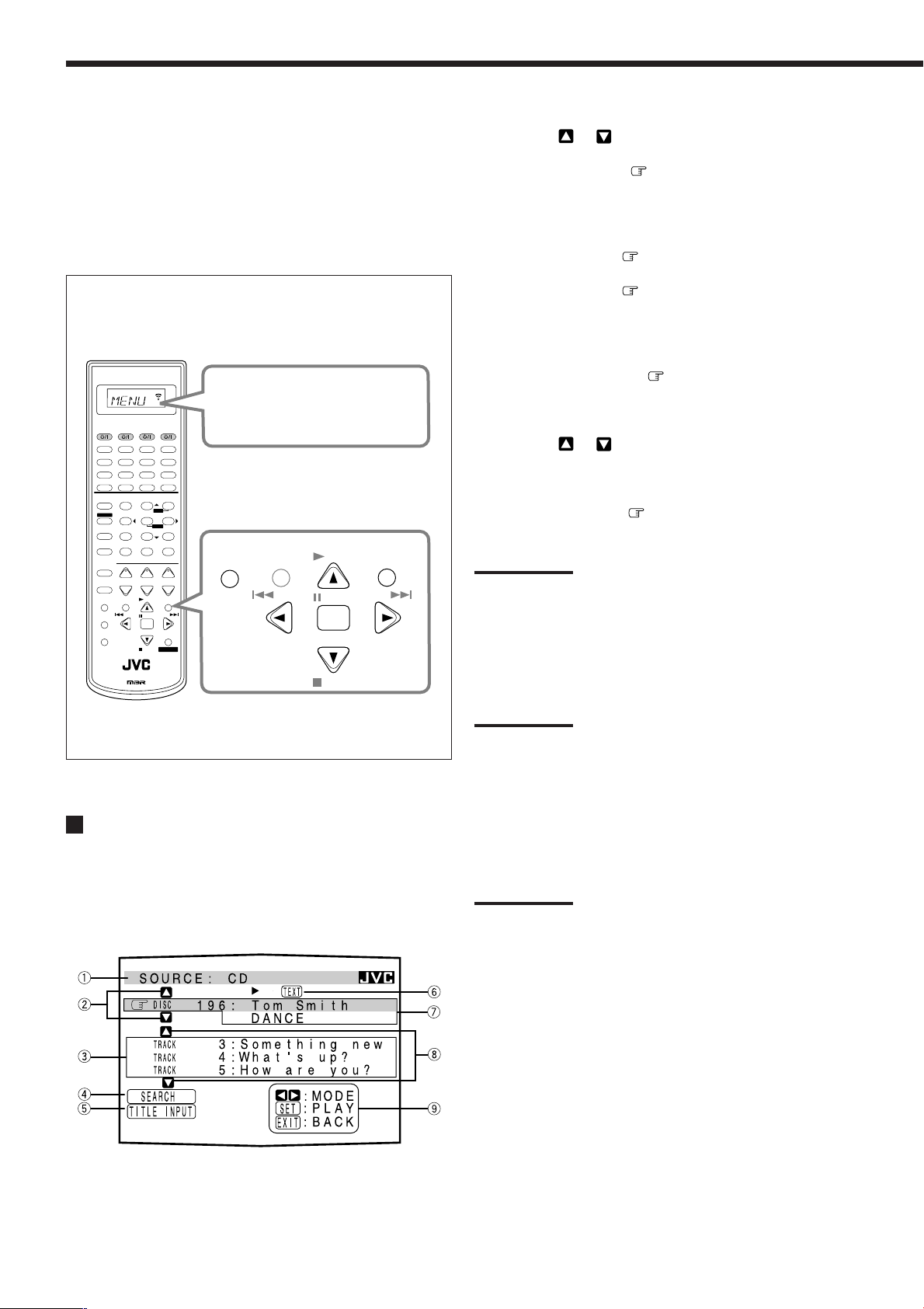
Operations:
To use this remote control system, you need to connect the TV to the
MONITOR OUT jack on the rear panel (see page 11), and set the
TV’s input mode to the proper position to which the receiver is
connected. Make sure you have connected a CD player or
MD recorder equipped with the TEXT COMPU LINK
remote control system. If not, you cannot use the
following functions.
On-Screen Operating buttons (on the remote control)
A/V CONTROL RECEIVER
When you press TEXT DISPLAY,
“MENU” appears on the remote
CATV/DB S VCR1 TV AUDIO
DVD
DVD MULTI
CD
CDR
TV/DBS VIDEO PHONO
TAPE/MD
VCR1 VCR2
SURR/DSP
ANALOG/DIGITAL
DSP
SURROUND
ANALOG
DIMMER
CATV/DBS
CONTROL
TV/VIDEO
DISPLAY
BASS
DIRECT
BOOST∗FRONT•L
SOUND
TEST
7/P
DIGITAL EQ
MUTING
∗
10
RETURN FM MODE 1 00
+−+−+
CH/
∗
TEXT
MENU
REC
PAUSE
DOWN – TUNING – UP
SLEEP
RM-SRX8020J
∗
SURR•L∗SURR•R
∗
SBACK•L∗SBACK•R
∗
LEVEL
TV VOL
/REW
REMOTE CONTROL
OFF
∗
231
MENU
CENTER∗SUBWFR
564
ENTER
89
0
PLAY
PAUSE
SET
CONTROL
STOP
FM/AM
FRONT•R
VOLUME
FF/
USB
INPUT
+10
+
−
EXIT
control display window.
TEXT
DISPLAY
MENU
/REW
DOWN – TUNING – UP
PLAY
PAUSE
SET
STOP
EXIT
FF/
1 Source name: CD or MD
2 Select
or , then press SET to change the disc.
3 Track numbers and track titles.
• When you move to a track number, you can
change the track information by pressing 2 or 3.
Each time you press the button, track information
alternates between its track title and its performer.
(You can also start playing the track by pressing SET.)
4 Select this (move
in front), then press SET to go to
the DISC SEARCH screen (see page 46).
5 Select this (move in front), then press SET to go to
the TITLE INPUT screen (see page 47).
6 This appears only when a CD Text is selected.
7 Disc information such as the disc title, performer, and
music genre.
When this is selected (
in front), you can change the
disc information by pressing 2 or 3. Each time you
press the button, disc information (see “Note on 7”)
changes.
8 Select
or , then press SET to change the track.
9 Usable buttons and their functions for the current
selection.
Indication here will be changed according to what is
currently selected (
in front) on the screen. See “Note
on 9.”
Note on 7:
The following information will appear on the display:
• For CD Texts—Disc title, Performer, Genre, Song writer, Composer,
Arranger, Message
Only recorded information will be shown. If there is no data,
“NO DATA” will appear.
• For MDs—Disc title
If there is no data, “NO DATA” will appear.
Showing the Disc Information on the TV
Screen
Press TEXT DISPLAY while “CD” or “MD” is
selected as the source.
The Disc Information screen appears on the TV.
Note on 9:
For example, SET button will be used to start play (PLAY), to go to the
next screen (ENTER), and to determine the selection (ENTER).
To exit from the Disc information screen
Press EXIT.
Notes:
• The on-screen display will disappear in the following cases:
– if no operation is done for about 10 minutes.
– if you do any operation other than explained in this section.
• To control an MD recorder using the TEXT COMPU LINK remote
control system, you have to change the source name shown on the
display from “TAPE” to “MD.” (See page 17.)
• Some special characters and marks cannot be displayed correctly.
45
Page 49

Searching for a Disc (Only for the CD player)
Search for a disc by its performer:
1. Press TEXT DISPLAY while “CD” is selected as
the source.
The Disc Information screen appears on the TV.
2. Press 5 or ∞ to move
to “SEARCH,” then
press SET.
The DISC SEARCH screen
appears.
3. Press 5 or ∞ to move
to “PERFORMER,”
then press SET.
The PERFORMER SEARCH
screen appears.
Search for a disc by its disc title:
1. Press TEXT DISPLAY while “CD” is selected as
the source.
The Disc Information screen appears on the TV.
2. Press 5 or ∞ to move
to “SEARCH,” then
press SET.
The DISC SEARCH screen
appears.
3. Press 5 or ∞ to move
to “DISC TITLE,”
then press SET.
The DISC TITLE SEARCH
screen appears.
4. Press 5 / ∞ / 2 / 3 to move in front of the
first character of the performer you want to
search for, then press SET.
To correct the incorrect entry, press 5 / ∞ / 2 / 3 to move
in front of the correct character, then press SET.
Note:
Symbols such as @, # or $ are not be available for search.
5. Press SET again.
Disc search starts, then the
SEARCH RESULT screen
showing the performers
appears.
6. On the SEARCH RESULT screen, you can do the
following:
• Changing the indication of the disc information: Press 5 or
∞ to move
time you press 2 or 3, the disc information alternates
between its performer and its disc title.
• Starting a disc play and going to the Disc Information
screen (see page 45): Press 5 or ∞ to move
searched-for disc, then press SET.
• Showing unseen disc information (if more than 5 discs are
listed as a result of the search): Press 5 or ∞ until they
appear.
• Going back to the PERFORMER SEARCH screen: Press
EXIT.
to a searched-for disc, then press 2 or 3. Each
to a
4. Press 5 / ∞ / 2 / 3 to move in front of the
first character of the disc title you want to search
for, then press SET.
To correct the incorrect entry, press 5 / ∞ / 2 / 3 to move
in front of the correct character, then press SET.
Note:
Symbols such as @, # or $ are not be available for search.
5. Press SET again.
Disc search starts, then the
SEARCH RESULT screen
showing the disc titles
appears.
6. On the SEARCH RESULT screen, you can do the
following:
• Changing the indication of the disc information: Press 5 or
∞ to move
time you press 2 or 3, the disc information alternates
between its performer and its disc title.
• Starting a disc play and going to the Disc Information
screen (see page 45): Press 5 or ∞ to move to a
searched-for disc, then press SET.
• Showing unseen disc information (if more than 5 discs are
listed as a result of the search): Press 5 or ∞ until they
appear.
• Going back to the DISC TITLE SEARCH screen: Press
EXIT.
to a searched-for disc, then press 2 or 3. Each
46
Page 50

Search for a disc by its genre:
1. Press TEXT DISPLAY while “CD” is selected as
the source.
The Disc Information screen appears on the TV.
2. Press 5 or ∞ to move
to “SEARCH,” then
press SET.
The DISC SEARCH screen
appears.
Entering the Disc Information
For the CD Player with the disc memory function:
You can use the disc memory function through this receiver.
The disc information (its performer, disc title, and music genre) of
normal audio CDs will be stored into the memory built in the CD
player.
For the disc memory function, refer to the manual supplied with
your CD player.
• The performer, disc title, and music genre information are usually
recorded in a CD Text. However, if a CD Text has no genre
information recorded on the disc itself, you can input its music
genre by yourself.
3. Press 5 or ∞ to move
to “GENRE,” then
press SET.
The GENRE SEARCH screen
appears.
4. Press 5 or ∞ to move
to the genre you
want to search for, then
press SET.
To show the unseen genres,
press 5 or ∞ until they
appear.
Disc search starts, then the SEARCH RESULT screen showing
the disc titles appears.
5. On the SEARCH RESULT screen, you can do the
following:
• Changing the indication of the disc information: Press 5
or ∞ to move
Each time you press 2 or 3, the disc information alternates
between its performer and its disc title.
• Starting a disc play and going to the Disc Information
screen (see page 45): Press 5 or ∞ to move
searched-for disc, then press SET.
• Showing unseen disc information (if more than 5 discs are
listed as a result of the search): Press 5 or ∞ until they
appear.
• Going back to the GENRE SEARCH screen: Press EXIT.
to a searched-for disc, then press 2 or 3.
to a
Note:
You can enter the TITLE INPUT screen for a CD Text and input its
titles. However, you cannot store the titles you have input for a CD
Text.
Example: Entering the following information for Disc 1
Performer: “MICHAEL”
Disc title: “MY FAVORITE”
1. Press TEXT DISPLAY while “CD” is selected as
the source.
The Disc Information screen appears on the TV.
2. Press 5 or ∞ to move
to “TITLE INPUT,”
then press SET.
The TITLE INPUT/
PERFORMER screen appears.
3. Press 5 / ∞ / 2 / 3 to move in front of a
character you want, then press SET to enter the
character.
• If the current CD is a CD Text, go to step 5 without entering
the performer.
To use the lower case letters, press 5 / ∞ / 2 / 3 to move
to , then press SET.
To use the upper case letters again, press 5 / ∞ / 2 / 3 to
move to , then press SET.
47
Page 51

4. Repeat step 3 until you
finish putting a
performer name (up to
32 characters).
To insert a space, press 5 / ∞
/ 2 / 3 to move
then press SET.
To correct an incorrect character:
1) Press 5 / ∞ / 2 / 3 to move
SET until the incorrect character is selected.
2) Press 5 / ∞ / 2 / 3 to move
to erase the character.
3) Press 5 / ∞ / 2 / 3 to move
character, then press SET to enter the correct character.
to ,
to + or =, then press
to , then press SET
in front of the correct
For the MD recorder:
You can write the disc information (disc title and song titles) onto
the disc. You can only write the song title for the song currently
selected.
• If you have the CD-MD combination deck, you can also enter the
disc information (its performer, disc title, and its music genre) of
normal audio CDs into the memory built in the CD-MD
combination deck. (To do this, follow the procedure of “For the
CD Player with the disc memory function” on page 47.)
• If you change the disc or song title with more than 32 characters,
the characters following 32nd will be erased from the title.
1. Press TEXT DISPLAY while “MD” is selected as
the source.
The Disc Information screen appears on the TV.
5. Press 5 / ∞ / 2 / 3 to
move
to “DISC 1:
MICHAEL (in this
example),” then press
SET.
The TITLE INPUT/DISC
TITLE screen appears.
6. Enter the disc title,
referring to steps 3 and
4.
• If the current CD is a CD
Text, go to the next step
without entering the disc
title.
7. Press 5 / ∞ / 2 / 3 to
move
to “DISC 1:
MY FAVORITE (in this
example),” then press
SET.
The TITLE INPUT/DISC 1
GENRE screen appears.
8. Press 5 or ∞ to move to the genre you want,
then press SET.
The Disc Information screen appears again.
To show the unseen genres, press 5 or ∞ until they appear.
2. Press 5 or ∞ to move
to “TITLE INPUT,”
then press SET.
The DISC TITLE INPUT
screen appears.
3. Enter the title,
referring to steps 3 and
4 of “For the CD Player
with the disc memory
function.”
• You can enter up to 32
characters for the disc title.
4. Press 5 / ∞ / 2 / 3 to
move
to the disc title
you have just entered,
then press SET.
The disc title is stored into the
memory and the SONG
TITLE INPUT screen for the
currently selected song appears.
• You can enter a song title for the song currently selected.
5. Enter the song title, referring to steps 3 and 4 of
“For the CD Player with the disc memory
function.”
• You can enter up to 32 characters for the song title.
6. Press 5 / ∞ / 2 / 3 to move to the song title
you have just entered, then press SET.
The song title is stored into the memory and the Disc
Information screen appears again.
48
Page 52

AV COMPU LINK Remote Control System
The AV COMPU LINK remote control system allows you to operate JVC’s video components (TV, VCR, and DVD player)
through the receiver.
This receiver is equipped with the AV COMPU LINK-III, which adds a function to operate JVC’s video components through the video
components terminals. To use this remote control system, you need to connect the video components you want to operate, following the
diagrams below and the procedure on the next page.
CONNECTIONS 1: AV COMPU LINK Connection
VCR 1
(VCR connected to
VCR 1 jacks)
VHS
DVD player
DVD
AV
COMPU LINK-
TV
ΙΙΙ
AV
COMPU LINK
AV
COMPU LINK
IMPORTANT:
The AV COMPU LINK remote control system cannot control the
DBS tuner connected to the TV SOUND/DBS and DBS component
video jacks, and video components connected to the VIDEO and
VCR 2 jacks on the receiver.
AV
COMPU LINK EX
AV
COMPU LINK-
ΙΙΙ
CAUTION:
You can only connect to the TV
with the AV COMPU LINK EX or
AV COMPU LINK-III jack. DO
NOT connect to the TV with AV
COMPU LINK RECEIVER/AMP
jack.
Notes:
• When connecting the receiver and a TV with the AV COMPU LINK EX terminal by using a component video cable, you cannot use automatic
selection of TV’s input mode (see page 50).
• When connecting only the VCR 1 or DVD player to this receiver, connect it directly to the receiver using cables with the monaural mini-plugs.
CONNECTIONS 2: Video Cable Connection
This receiver is equipped with three types of the video terminals—S-video, composite video, and component video, and the signals coming
into this receiver through one type of video jacks can output only through the jack of the same type. So you need to connect the VCR and/or
DVD player to the TV using one of the following three ways:
• When using the AV COMPU LINK remote control system, set the component video input for the DVD player and the DBS tuner
correctly (see “7 Setting the Component Video Input” on page 25); otherwise, the correct input for this receiver will not be selected on
the TV.
CASE 1
CASE 2
CASE 3
When connecting the source equipment to the receiver through the S-video jacks, connect this receiver
to the TV’s Video Input 1 jack using S-video cables.
Source
Equipment
S-video cable
RX-8022PSL
S-video cable
TV
To Video Input 1
When connecting the source equipment to the receiver through the composite video jacks, connect this
receiver to the TV’s Video Input 2 jack (composite video input) using composite video cables.
Source
Equipment
Composite
video cable
RX-8022PSL
Composite
video cable
TV
To Video Input 2
(Composite)
When connecting the source equipment to the receiver through the component video jacks, connect this
receiver to the TV’s Video Input 2 jack (component video input) using component video cables.
Source
Equipment
Component
video cable
RX-8022PSL
Component
video cable
TV
To Video Input 2
(Component)
49
Page 53

1. If you have already plugged your VCR 1 (VCR
connected to the VCR 1 jacks), DVD player, TV
and this receiver into the AC outlets, unplug their
AC power cords first.
2. Connect your VCR 1, DVD player, TV and this
receiver, using the cables with the monaural miniplugs (not supplied).
• See “CONNECTIONS 1” on the previous page.
3. Connect the audio input/output jacks on VCR 1,
DVD player, TV and this receiver using the cables
with RCA pin plugs.
• See pages 10 to 12.
4. Connect the video input/output jacks on VCR 1,
DVD player, TV and this receiver, using the
cables with RCA pin plugs, S-video plug or
component video plugs.
• See “CONNECTIONS 2” on the previous page.
One-Touch DVD Play
Simply by starting playback on the DVD player, you can enjoy the
DVD playback without setting other switches manually.
• When the DVD player is connected through the analog input jacks
on this receiver (and analog input is selected), the receiver
automatically turns on and changes the source to “DVD” or
“DVD MULTI.”
• When the DVD player is connected through the digital input
terminal on this receiver (and digital input is selected), the
receiver automatically turns on and changes the source to “DVD.”
The TV automatically turns on and changes the input mode to the
appropriate position so that you can view the playback picture.
Automatic Selection of TV’s Input Mode
• When you select “TV” as the source to play on the receiver, the
TV automatically changes the input mode to the TV tuner so that
you can watch TV.
• When you select “DVD,” “DVD MULTI,” “VCR 1,” “VCR 2,”
“VIDEO” or “DBS” as the source to play on the receiver, the TV
automatically changes the input mode to the appropriate position
(either Video Input 1 or Video Input 2) so that you can view the
playback picture.
5. Plug the AC power cords of the components and
the receiver into the AC outlets.
6. When turning on the TV for the first time after
the AV COMPU LINK connection, turn the TV
volume to the minimum using the TV volume
control on the TV.
7. Turn on the connected components first, then
turn on this receiver.
• When turning on the VCR 1 (VCR connected to the VCR 1
jacks), use the remote control supplied with this receiver
(press VCR1
The AV COMPU LINK remote control system allows you to use the
five basic functions listed below.
Remote Control of the TV, DVD player, and VCR Using
This Remote Control
See page 53 for details.
• Aim the remote control directly at the remote sensor on each
target component.
One-Touch Video Play
Simply by inserting a video cassette without its safety tab into the
VCR 1 (VCR connected to the VCR 1 jacks), you can enjoy the
video playback without setting other switches manually. The
receiver automatically turns on and changes the source to “VCR 1.”
The TV automatically turns on and changes the input mode to the
appropriate position so that you can view the playback picture.
When you insert a video cassette with its safety tab, press the play
33
(
3) button on the VCR 1 (VCR connected to the VCR 1 jacks) or on
33
the remote control. So, you can get the same result.
).
Notes:
• When you select “TV” as the source on the receiver, you cannot
see the menu on the TV screen since the AV COMPU LINK remote
control system automatically changes the TV’s input mode to the
TV tuner.
If you do not mind stopping listening to the TV sounds, you can
then show the on-screen displays after changing the TV’s input
mode to the appropriate position (either Video Input 1 or Video
Input 2).
• This function does not work when you connect this receiver and the TV
with the AV COMPU LINK using the TV’s AV COMPU LINK EX
terminal. In this case, reconnect the TV referring to CASE 1 or CASE 2
on page 49.
Automatic Power On/Off
The TV, VCR 1 (the VCR connected to the VCR 1 jacks), and DVD
player turn on and off along with the receiver.
When you turn on the receiver;
• If the previously selected source is “VCR 1,” the TV and VCR 1
will turn on automatically.
• If the previously selected source is “DVD” or “DVD MULTI,” the
TV and DVD player will turn on automatically.
• If the previously selected source is “VIDEO,” “VCR 2,” “TV” or
“DBS,” only the TV will turn on automatically.
When you turn off the receiver, the TV, VCR 1 and the DVD player
will turn off.
Note:
If you turn off the receiver while recording on the VCR 1, the VCR 1
will not turn off, but continue recording.
50
Page 54

Operating JVC’s Audio/Video Components
You can operate JVC’s audio and video components with this receiver’s remote control, since control signals for JVC’s
components are preset in the remote control.
Operating Audio Components
IMPORTANT:
To operate JVC’s audio components using this remote control:
• You need to connect JVC’s audio components through the COMPU
LINK (SYNCHRO) jacks (see page 43) in addition to the
connections using cables with RCA pin plugs (see pages 8 and 9).
• Aim the remote control directly at the remote sensor on the
receiver.
• If you use the buttons on the front panel or the menu function to
choose a source, the remote control will not operate that source.
To operate a source with the remote control, the source must be
selected using source selecting buttons on the remote control.
• To operate a cassette deck or MD recorder using the COMPU LINK
remote control system, set the source name correctly. (See page 17.)
• Refer also to the manuals supplied with your components.
A/V CONTROL RECEIVER
CATV/DBS VCR1 TV AUDIO
DVD MULTIDVD
CD
FM/AM
TV/DBS VIDEO PHONO
VCR1 VCR2
SURROUND
ANALOG
DIRECT
SOUND
DIMMER
MUTING
CATV/DBS
CONTROL
TV/VIDEO
TEXT
DISPLAY
REC
PAUSE
SLEEP
RM-SRX8020J REMOTE CONTROL
Note:
When you press one of the source selecting buttons, the
operation mode appears on the display window. For example,
the above illustration shows the remote control now works for
CD operation.
Buttons Indications
FM/AM TUNER
CD CD
CDR CDR
PHONO PHONO
TAPE/MD TAPE
CONTROL (repeatedly)*
SOUND SOUND
*
By pressing CONTROL repeatedly, you can select “VCR1,”
“TAPE,” “CDR” or “CDDSC” as the source.
CDR
TAPE/MD
SURR/DSP
DSP
OFF
BASS
BOOST∗FRONT•L
231
MENU
TEST
CENTER∗SUBWFR
∗
564
ENTER
SURR•L∗SURR•R
∗
7/P
89
SBACK•L∗SBACK•R
DIGITAL EQ
∗
∗
0
10
RETURN FM MODE 100
+−+−+
CH/
LEVEL
TV VOL
∗
PLAY
MENU
/REW
PAUSE
SET
DOWN – TUNING – UP
STOP
USB
ANALOG/DIGITAL
INPUT
FRONT•R
∗
+10
+
VOLUME
−
EXIT
FF/
CONTROL
VCR1
CDDSC
TAPE
CDR
Tuner
You can always perform the following operations on a tuner:
FM/AM :Alternate between FM and AM.
After pressing FM/AM, you can perform the following operations
on a tuner:
1 – 10, +10 :Select a preset channel number directly.
For channel number 5, press 5.
For channel number 15, press +10, then 5.
For channel number 20, press +10, then 10.
TUNING UP/DOWN :Tune into stations.
FM MODE :Change the FM reception mode.
Sound control section (Amplifier)
You can always perform the following operations:
SURROUND :Turn on and select Surround modes
DSP :Turn on and select DSP modes.
SURR/DSP OFF :Turn off Surround and DSP modes.
After pressing SOUND, you can perform the following operations:
FRONT•L then LEVEL +/– :Adjust the left front speaker output
level. “FRL” appears on the display.
FRONT•R then LEVEL +/– :Adjust the right front speaker output
level. “FRR” appears on the display.
CENTER then LEVEL +/– : Adjust the center speaker output level.
“CTR” appears on the display.
SURR•L then LEVEL +/– : Adjust the left surround speaker output
level. “SURRL” appears on the display.
SURR•R then LEVEL +/– :Adjust the right surround speaker output
level. “SURRR” appears on the display.
SBACK•L then LEVEL +/– :Adjust the left surround back speaker
output level. “SBKL” appears on the
display.
SBACK•R then LEVEL +/– :Adjust the right surround back speaker
output level. “SBKR” appears on the
display.
SUBWFR then LEVEL +/– :Adjust the subwoofer output level.
“S-WFR” appears on the display.
DIGITAL EQ then LEVEL+/– :Select the audio band and adjust its
frequency level. “EQ” appears on the
display.
TEST :Turn on or off the test tone output.
BASS BOOST :Turn on or off Bass Boost function.
Note:
After adjusting sounds, press the corresponding source selecting
button to operate your target source by using the 10 keys; otherwise,
the 10 keys cannot be used for operating your target source.
51
Page 55

CD player
After pressing CD, you can perform the following operations on a
CD player:
3 PLAY :Start playing.
4 :Return to the beginning of the current (or previous)
track.
¢ :Skip to the beginning of the next track.
7 STOP :Stop playing.
8 PAUSE :Pause playing. To resume, press 3 PLAY.
1 – 10, +10 :Select a track number directly.
For track number 5, press 5.
For track number 15, press +10, then 5.
For track number 20, press +10, then 10.
For track number 30, press +10, +10, then 10.
1 – 10, +10 :Select a track number directly.
For track number 5, press 5.
For track number 15, press +10, then 5.
For track number 20, press +10, then 10.
For track number 30, press +10, +10, then 10.
REC PAUSE :Enter recording pause by pressing this button.
To start recording again, press this button, then
3 PLAY.
Note:
You can use either CDR or CONTROL to activate the buttons listed
above. If you press CDR, the playing source also changes. On the
other hand, if you press CONTROL repeatedly to select “CDR,” the
playing source does not change.
CD changer
After selecting “CDDSC” by pressing CONTROL repeatedly, you
can perform the following operations on a CD changer:
3 PLAY :Start playing.
4 :Return to the beginning of the current (or
previous) track.
¢ :Skip to the beginning of the next track.
7 STOP :Stop playing or recording.
8 PAUSE :Pause playing. To resume, press 3 PLAY.
1 – 6, 7/P :Select the number of a disc installed in a CD
changer.
After pressing CD, you can perform the following operations on a
CD changer:
1 – 10, +10 :Select a track number directly.
For track number 5, press 5.
For track number 15, press +10, then 5.
For track number 20, press +10, then 10.
For track number 30, press +10, +10, then 10.
Example:
• Selecting disc number 4, track number 12, and starting playback.
1. Press CONTROL repeatedly until “CDDSC” appears on
the display window, then press 4.
2. Press CD, then press +10, 2.
Turntable
After pressing PHONO, you can perform the following operations
on a turntable:
3 PLAY :Start playing.
7 STOP :Stop playing.
CD recorder
After pressing CDR (or selecting “CDR” by pressing CONTROL
repeatedly), you can perform the following operations on a CD
recorder:
3 PLAY :Start playing.
4 :Return to the beginning of the current (or
previous) track.
¢ :Skip to the beginning of the next track.
7 STOP :Stop playing or recording.
8 PAUSE :Pause playing. To resume, press 3 PLAY.
Cassette deck
After pressing TAPE/MD (or selecting “TAPE” by pressing
CONTROL repeatedly), you can perform the following operations
on a cassette deck:
3 PLAY :Start playing.
REW :Fast wind the tape from right to left.
FF :Fast wind the tape from left to right.
7 STOP :Stop playing or recording.
8 PAUSE :Pause playing. To resume, press 3 PLAY.
REC PAUSE :Enter recording pause by pressing this button.
To start recording again, press this button, then
3 PLAY.
Notes:
• When you use a cassette deck, change the source name
connected to TAPE/MD jacks correctly (see page 17).
• You can use either TAPE/MD or CONTROL to activate the buttons
listed above. If you press TAPE/MD, the playing source also
changes. On the other hand, if you press CONTROL repeatedly to
select “TAPE,” the playing source does not change.
MD recorder
After pressing TAPE/MD (or selecting “TAPE*” by pressing
CONTROL repeatedly), you can perform the following operations
on the MD recorder:
3 PLAY :Start playing.
4 :Return to the beginning of the current (or
previous) track.
¢ :Skip to the beginning of the next track.
7 STOP :Stop playing or recording.
8 PAUSE :Pause playing. To resume, press 3 PLAY.
REC PAUSE :Enter recording pause by pressing this button.
To start recording again, press this button then
3 PLAY.
Notes:
• When you use an MD recorder, change the source name
connected to TAPE/MD jacks correctly (see page 17).
• You can use either TAPE/MD or CONTROL to activate the buttons
listed above. If you press TAPE/MD, the playing source also
changes. On the other hand, if you press CONTROL repeatedly to
select “TAPE*,” the playing source does not change.
*
Selecting “TAPE” will allow you to control the MD recorder.
52
Page 56

Operating Video Components
∗FRONT•L
TEST ∗CENTER
∗SURR•L
23
456
8
MENUMENU
ENTERENTER
∗FRONT•R
∗SUBWFR
IMPORTANT:
To operate JVC’s video components using this remote control:
• You need to connect JVC’s video components through the AV
COMPU LINK jacks (see page 49) in addition to the connections
using cables with RCA pin plugs (see pages 10 to 12).
• Some JVC’s VCRs can accept two types of the control signals—
remote code “A” and “B.” Before using this remote control, make
sure that the remote control code of the VCR connected to the VCR 1
jacks is set to code “A.”
– When another JVC’s VCR is connected to the VCR 2 or VIDEO
jacks, set its remote control code to code “B.” (This remote
control cannot emit the control signals of code “B.”)
• When using the remote control, aim the remote control directly at
the remote sensor on each component, not on the receiver.
A/V CONTROL RECEIVER
CATV/DBS VCR1 TV AUDIO
DVD
DVD MULTI
CD
FM/AM
TV/DBS VIDEO PHONO
VCR1 VCR2
SURROUND
ANALOG
DIRECT
SOUND
DIMMER
MUTING
CATV/DBS
CONTROL
TV/VIDEO
TEXT
DISPLAY
REC
PAUSE
SLEEP
RM-SRX8020J
CDR
TAPE/MD
DSP
SURR/DSP
OFF
BASS
BOOST∗FRONT•L
231
MENU
TEST
CENTER∗SUBWFR
∗
564
ENTER
SURR•L∗SURR•R
∗
7/P
89
SBACK•L∗SBACK•R
DIGITAL EQ
∗
∗
0
10
RETURN FM MODE 100
+−+−+
CH/
LEVEL
TV VOL
∗
PLAY
MENU
/REW
PAUSE
SET
DOWN – TUNING – UP
STOP
REMOTE CONTROL
USB
ANALOG/DIGITAL
INPUT
FRONT•R
∗
+10
+
VOLUME
−
EXIT
FF/
CONTROL
VCR 1 (VCR connected to the VCR 1 jacks)
You can always perform the following operations:
VCR1
:Turn on or off the VCR 1 (VCR connected to
the VCR 1 jacks).
After pressing VCR1 (or selecting “VCR1” by pressing CONTROL
repeatedly), you can perform the following operations on the VCR 1
(VCR connected to the VCR 1 jacks):
1 – 9, 0 :Select the TV channels on a VCR.
3 PLAY :Start playing.
REW :Rewind a tape.
FF :Fast wind a tape.
7 STOP :Stop playing or recording.
8 PAUSE :Pause playing. To resume, press 3 PLAY.
REC PAUSE :Enter recording pause by pressing this button.
To start recording again, press this button then
3 PLAY.
CH +/– :Change the TV channels on the VCR.
Note:
You can use either VCR1 or CONTROL to activate the buttons listed
above. If you press VCR1, the playing source also changes. On the
other hand, if you press CONTROL repeatedly to select “VCR1,” the
playing source does not change.
DVD player
After pressing DVD or DVD MULTI, you can perform the
following operations on a DVD player:
3 PLAY :Start playing.
4 :Return to the beginning of the current (or
previous) chapter.
¢ :Skip to the beginning of the next chapter.
7 STOP :Stop playing.
8 PAUSE :Pause playing. To resume, press 3 PLAY.
After pressing DVD or DVD
MULTI, these buttons can be used
for the DVD menu operations.
Note:
For detailed menu operations, refer
to the instructions supplied with the
discs or the DVD player.
Note:
When you press one of the source selecting buttons, the
operation mode appears on the display window. For example,
the above illustration shows the remote control now works for
VCR 1 operation.
DVD or DVD MULTI DVD
CONTROL (repeatedly)*
*
By pressing CONTROL repeatedly, you can select “VCR1,”
“TAPE,” “CDR” or “CDDSC” as the source.
53
Buttons Indications
VCR1 VCR1
TV/DBS TV
VCR1
CDDSC
TAPE
CDR
TV
You can always perform the following operations:
TV :Turn on or off the TV.
TV VOL +/– :Adjust the volume.
TV/VIDEO :Set the input mode (either TV or VIDEO).
After pressing TV/DBS, you can perform the following operations
on a TV:
CH +/– :Change the channels.
1 – 9, 0, 100+ :Select the channels.
RETURN :Alternate between the previously selected
channel and the current channel.
Page 57

Operating Other Manufacturers’ Video Equipment
This remote control supplied with the receiver can transmit control
signals for other manufacturers’ TVs, CATV converters, DBS
tuners, VCRs and DVD players. By changing the transmittable
signals from preset ones to the other manufacturers’, you can
operate the other manufacturers’ components using this remote
control.
When operating the other manufacturers’ components, refer also to
the manuals supplied with them. To operate these components with
the remote control, first you need to set the manufacturers’ codes for
each TV, CATV converters, DBS tuners VCR and DVD players.
After replacing batteries for the remote control, you need to set the
manufactures’ codes again.
A/V CONTROL RECEIVER
CATV/DBS VCR1 TV AUDIO
DVD
DVD MULTI
CD
FM/AM
TV/DBS VIDEO PHONO
VCR1 VCR2
SURROUND
ANALOG
DIRECT
SOUND
DIMMER
MUTING
CATV/DBS
CONTROL
TV/VIDEO
TEXT
DISPLAY
REC
PAUSE
SLEEP
RM-SRX8020J
CDR
TAPE/MD
DSP
SURR/DSP
OFF
BASS
BOOST∗FRONT•L
231
MENU
CENTER∗SUBWFR
TEST
∗
564
ENTER
SURR•L∗SURR•R
∗
7/P
89
SBACK•L∗SBACK•R
DIGITAL EQ
∗
∗
0
10
RETURN FM MODE 100
+−+−+
CH/
LEVEL
TV VOL
∗
PLAY
MENU
/REW
PAUSE
SET
DOWN – TUNING – UP
STOP
REMOTE CONTROL
USB
ANALOG/DIGITAL
INPUT
FRONT•R
∗
+10
+
VOLUME
−
EXIT
FF/
CONTROL
Note:
When you press one of the source selecting buttons, the
operation mode appears on the display window. For example,
the above illustration shows the remote control now works for
TV operation.
Buttons Indications
TV/DBS TV
CATV/DBS CONTROL
VCR1 VCR1
DVD or DVD MULTI DVD
CATV
To change the transmittable signals for
operating another manufacturer’s TV
1. Press and hold TV .
2. Press TV/DBS.
“CALL” appears on the remote control display window.
3. Enter a manufacturer’s code using buttons 1–9,
and 0.
See the list below to find the code.
4. Release TV .
The following buttons can be used for operating the TV:
TV
:Turn on and off the TV.
TV VOL +/– :Adjust the volume.
TV/VIDEO :Set the input mode (either TV
or VIDEO).
After pressing TV/DBS, you can perform the following
operations on the TV:
CH +/– :Change the channels.
1 – 10, 0, 100+ (+10) :Select the channels.
The 10-key will function as the
ENTER button if your TV requires
pressing ENTER after selecting a
channel number.
Notes:
• Refer also to the manual supplied with your TV.
• All the functions listed above may not be assigned to the
buttons for some TVs.
• If you cannot change the channels of some TVs by pressing
number buttons, press CH +/– for changing the channels.
5. Try to operate your TV by pressing TV .
When your TV turns on or off, you have entered the correct
code.
If there are more than one code listed for your brand of TV,
try each one until the correct one is entered.
Manufacturer Codes
JVC 00
*, 02, 13,
14, 47, 74
AKAI 01, 02
BLAUPUNKT 03, 04
FISHER 01, 05
GRUNDIG 03, 06, 07
HITACHI 08, 09, 10, 49
IRADDIO 02
ITT/NOKIA 11, 12
LOEWE 06, 15, 16
MAGNAVOX 08, 17, 49
METS 50, 51, 52, 53
MITSUBISHI 08, 18, 19, 20
MIVAR 21
NORDMENDE 22, 23
OKANO 15
PANASONIC 24, 25, 26, 27
76
PHILIPS 15, 17, 28, 75
Manufacturers’ codes are subject to change without notice. If they
are changed, this remote control cannot operate the equipment.
Manufacturer Codes
QUELLE 52, 53, 54, 55,
56, 57, 58, 59,
60, 61, 62, 63,
64, 65, 66, 67
RCA/ 08, 24, 29, 30,
PROSCAN 31, 48
SABA 32, 33, 68, 69,
70
SAMSUNG 06, 08, 16, 34,
35, 49
SANYO 01, 05
SCHNEIDER 02, 15, 36
SHARP 37, 38, 77
SONY 39
TELEFUNKEN 40, 41, 42, 69
THOMSON 71, 72
TOSHIBA 37, 43, 44
ZENITH 45, 46
*Initial setting
54
Page 58
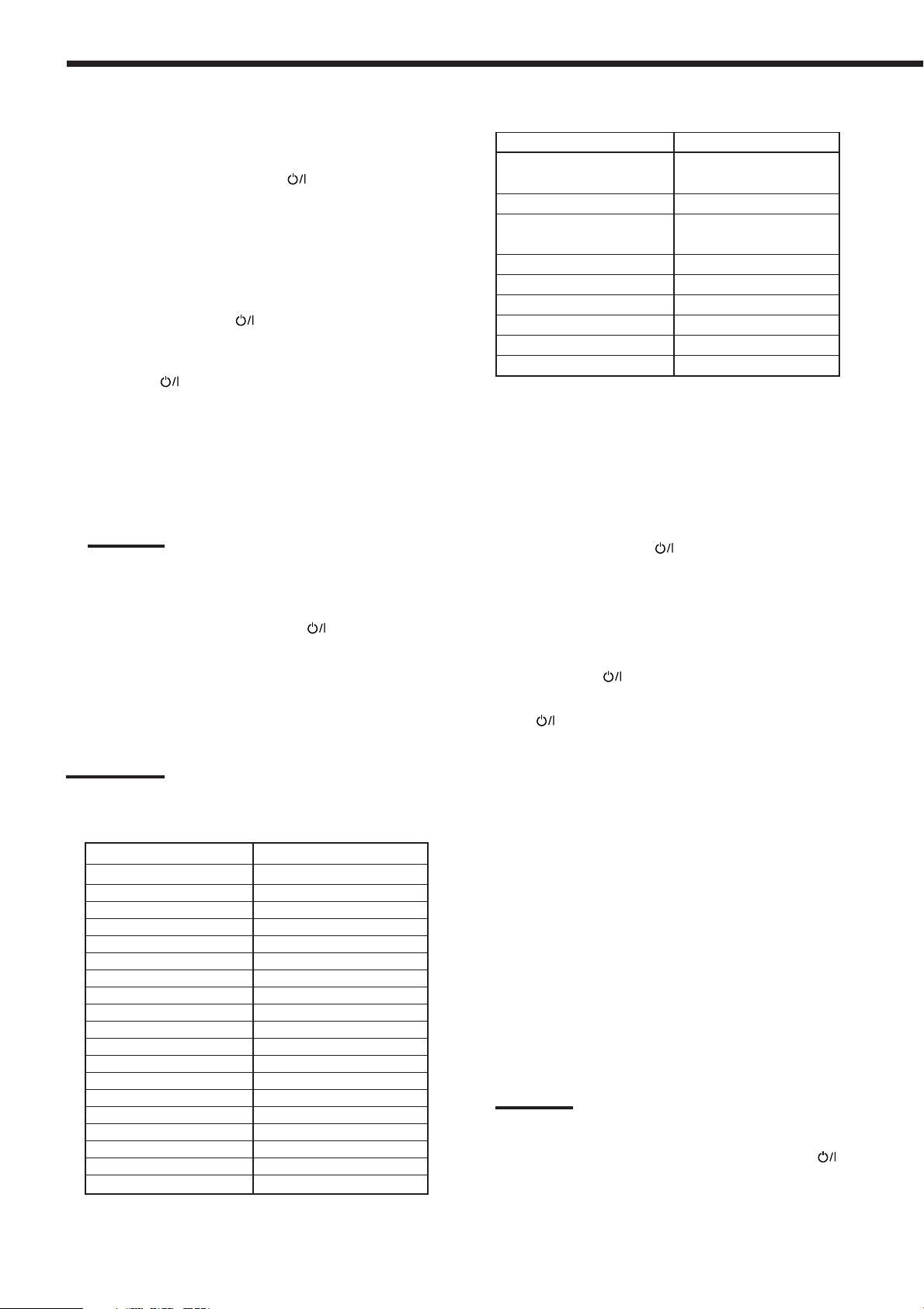
To change the transmittable signals for
operating a CATV converter or DBS tuner
1. Press and hold CATV/DBS .
2. Press CATV/DBS CONTROL.
“CALL” appears on the remote control display window.
3 Enter a manufacturer’s code using buttons 1–9,
and 0.
See the following lists to find the code.
4. Release CATV/DBS .
The following buttons can be used for operating the CATV
converter and DBS tuner:
CATV/DBS
CH +/– :Change the channels.
1 – 10, 0, 100+ (+10) :Select the channels.
:Turn on and off the CATV converter
or DBS tuner.
The 10-key will function as the
ENTER button if your equipment
requires pressing ENTER after
selecting a channel number.
For CATV converter
Manufacturer Codes
GENERAL INSTRUMENT 06, 07, 08, 09, 10, 11,
12, 13, 14, 29
HAMLIN/REGAL 01, 02, 03, 04, 05
JERROLD 06, 07, 08, 09, 10, 11,
12, 13, 14
OAK 15, 16, 17
PANASONIC 18, 19, 20
PIONEER 21, 22
SCIENTIFIC ATLANTA 23, 24, 25
TOCOM 26
ZENITH 27, 28
Manufacturers’ codes are subject to change without notice. If they
are changed, this remote control cannot operate the equipment.
To change the transmittable signals for
operating another manufacturer’s VCR
Note:
Refer also to the manual supplied with your CATV converter or
DBS tuner.
5. Try to operate your CATV converter or DBS
tuner by pressing CATV/DBS
When your CATV converter or DBS tuner turns on or off, you
have entered the correct code.
If there are more than one code listed for your brand of
CATV converter or DBS tuner, try each one until the correct
one is entered.
Note:
You cannot preset the signals for both the CATV converter and DBS
tuner at the same time.
For DBS tuner
Manufacturer Codes
JVC 56*, 57, 67
AMSTRAD 43, 44, 45, 46, 47, 48, 49
BLAUPUNKT 30
ECHOSTAR 50, 51, 67
GOLDSTAR 31
GRUNDIG 32, 33
HIRSHMANN 48, 52, 53, 54, 55
INSTRUMENT 68
ITT/NOKIA 34
KATHREIN 52, 58, 59, 60, 61, 62, 63
NEC 35, 36
ORBITECH 48
PHILIPS 37, 38
RCA 65
SAMSUNG 39, 40
SCHWAIGER 61, 64
SIEMENS 41, 42
SONY 66
TECHNISAT 48
.
*Initial setting
55
1. Press and hold VCR1 .
2. Press VCR1.
“CALL” appears on the remote control display window.
3. Enter manufacturer’s code using buttons 1–9,
and 0.
See the list on the next page to find the code.
4. Release VCR1 .
The following buttons can be used for operating the VCR:
VCR1
After pressing VCR1, you can perform the following operations
on the VCR:
CH +/– :Change the TV channels on the
1 – 10, 0, 100+ (+10) :Select the TV channels.
3 PLAY :Start playback.
REW :Rewind a tape.
FF :Fast wind a tape.
7 STOP :Stop playing or recording.
8 PAUSE: :Pause playing. To resume, press
REC PAUSE :Enter recording pause by pressing
Note:
Refer also to the manual supplied with your VCR.
:Turn on and off the VCR.
VCR.
The 10-key will function as the
ENTER button if your VCR requires
pressing ENTER after selecting a
channel number.
3 PLAY.
this button.
To start recording again, press this
button then 3 PLAY.
5. Try to operate your VCR by pressing VCR1 .
When your VCR turns on or off, you have entered the correct
code.
If there are more than one code listed for your brand of
VCR, try each one until the correct one is entered.
Page 59
Manufacturer Codes
∗FRONT•L
TEST ∗CENTER
∗SURR•L
23
456
8
MENUMENU
ENTERENTER
∗FRONT•R
∗SUBWFR
JVC 00*, 26, 27, 28, 29, 58
AIWA 01, 02
BELL & HOWELL 03
BLAUPUNKT 04, 05
CGM 06, 07
EMERSON 08, 10, 11, 12, 64, 65
FISHER 03, 14, 15, 16, 17
FUNAI 01
GE 18, 19, 20
GOLDSTAR 07
GOODMANS 13, 21
GRUNDIG 06, 22
HITACHI 18, 23, 24, 25, 66
LOEWE 07, 21
MAGNAVOX 04, 19, 24
MITSUBISHI 30, 31, 32, 33, 34, 35
NEC 26, 27
NOKIA 03, 36
NORDMENDE 38
ORION 09
PANASONIC 19, 24, 39, 40
PHILIPS 04, 19, 21, 24, 41, 42
PHONOLA 21
RCA/PROSCAN 04, 18, 19, 23, 24, 43, 44, 45
SABA 38, 46
SAMSUNG 45, 47, 59, 61, 62, 63
SANYO 03, 48, 49
SHARP 37, 50
SIEMENS 03, 51
SONY 52, 53, 54
TELEFUNKEN 55, 60
TOSHIBA 43, 44
ZENITH 56, 57
*Initial setting
Manufacturers’ codes are subject to change without notice. If they
are changed, this remote control cannot operate the equipment.
After pressing DVD or DVD MULTI,
these buttons can be used for the
DVD menu operations.
Note:
For detailed menu operations, refer to
the instructions supplied with the
discs or the DVD player.
Note:
Refer also to the manual supplied with your DVD player.
5. Try to operate your DVD player by pressing one
of the above buttons.
• DO NOT forget to turn on the DVD player before pressing
one of the above buttons.
If there are more than one code listed for your brand of
DVD, try each one until the correct one is entered.
Manufacturer Codes
JVC 00*, 02
DENON 01
PANASONIC 03
PHILIPS 13
PIONEER 04, 05, 06
RCA 07
SAMSUNG 08
SONY 09
TOSHIBA 10
YAMAHA 11, 12
*Initial setting
Manufacturers’ codes are subject to change without notice. If they
are changed, this remote control cannot operate the equipment.
To change the transmittable signals for
operating another manufacturer’s DVD player
1. Press and hold AUDIO .
2 Press DVD.
“CALL” appears on the remote control display window.
3. Enter a manufacturer’s code using buttons 1–9,
and 0.
See the following list to find the code.
4. Release AUDIO .
After pressing DVD or DVD MULTI, you can perform the
following operations on the DVD player:
3 PLAY :Start playing.
4 :Return to the beginning of the current (or
¢ :Skip to the beginning of the next chapter.
7 STOP :Stop playing.
8 PAUSE :Pause playing. To resume, press
previous) chapter.
3 PLAY.
56
Page 60

Troubleshooting
Use this chart to help you solve daily operational problems. If there is any problem you cannot solve, contact your JVC’s
service center.
PROBLEM
The display does not light up.
No sound from speakers.
Sound from one speaker only.
No sound from PC connected with a USB
cable.
Noise while reproducing PC sound
connected with a USB cable.
Sound from PC connected with a USB
cable is intermittent.
Continuous hiss or buzzing during FM
reception.
Occasional cracking noise during FM
reception.
Noise is heard while playing a record.
Howling during record playing.
No sound effect such as Surround mode,
DSP mode and digital equalization.
6.1-channel reproduction cannot be done
for Dolby Digital EX or DTS ES
software.
POSSIBLE CAUSE
The power cord is not plugged in.
Speaker signal cables are not connected.
The SPEAKERS ON/OFF 1 and
SPEAKERS ON/OFF 2 buttons are not
set correctly.
An incorrect source is selected.
Muting is activated.
An incorrect input mode (analog or
digital) is selected.
Connections are incorrect.
Speaker signal cables are not connected
properly.
The balance is set to one extreme.
An electrical shock is applied to the
receiver, PC, or USB cable.
USB device is not selected on the
computer.
“Mute” is selected on the PC.
Strong electromagnetic wave is emitted
from a nearby device such as TV
PC is subjected to excessive load due to
using other applications.
Incoming signal is too weak.
The station is too far away.
An incorrect antenna is used.
Antennas are not connected properly.
Ignition noise from automobiles.
A ground cable from the turntable is not
connected to the screw marked (H) on
the rear panel.
Your turntable is too close to the
speakers.
The Analog Direct is turned on.
Software or setting is not for Dolby
Digital EX or DTS ES software.
SOLUTION
Plug the power cord into an AC outlet. (See page 15.)
Check speaker wiring and reconnect if necessary.
(See pages 6 to 8.)
Press SPEAKERS ON/OFF 1 and
SPEAKERS ON/OFF 2 correctly. (See page 18.)
Select the correct source.
Press MUTING to cancel the mute. (See page 20.)
Select the correct input mode (analog or digital).
(See page 19.)
Check connections.
For analog connections, see pages 8 to 12.
For digital connections, see page 13.
For USB connection, see page 14.
Check speaker wiring and reconnect if necessary.
(See pages 6 to 8.)
Adjust the balance properly. (See page 40.)
Turn off the receiver once, then turn it on again and
restart application installed in the PC.
Select “USB Audio Device [1]” for “Playback” of
“Audio.” (See page 14.)
Refer to the manuals supplied with your PC.
Check if the volume is set at low level.
Refer to the manuals supplied with your PC.
Move the PC away from the device such as TV
emitting strong electromagnetic wave.
Close the applications you do not use.
Connect an outdoor FM antenna or contact your
dealer. (See page 5.)
Select a new station.
Check with your dealer to be sure you have the
correct antenna.
Check connections. (See pages 5 and 6.)
Move the antenna further from automobile traffic.
Connect the cable to the screw marked (H) on the
rear panel.
Move the speakers away from the turntable.
Turn off the Analog Direct. (See page 30.)
Play back software bearing the mark or
.
Set “EX/ES” setting to “AUTO.” (See page 23.)
57
Page 61

PROBLEM
POSSIBLE CAUSE
SOLUTION
“OVERLOAD” starts flashing on the
display.
The STANDBY lamp lights up after
turning on the power, and soon the
receiver turns off again (into standby
mode).
Remote control does not work.
Remote control does not work intendedly.
Speakers are overloaded because of
high volume.
Speakers are overloaded because of
short circuit of speaker terminals.
The receiver is overloaded because of
high voltage.
There is an obstruction between the
remote sensor on the receiver and the
remote control.
Batteries are weak.
An incorrect remote control operation
mode is selected.
1.Press STANDBY/ON on the front panel to
turn off the receiver.
2.Stop the playback source.
3.Turn on the receiver again and adjust the volume.
Press STANDBY/ON on the front panel to turn
off the receiver, then check the speaker wiring.
If “OVERLOAD” does not disappear, unplug the AC
power cord, then plug it back again.
If speaker wiring is not short-circuited, contact your
dealer.
Press STANDBY/ON on the front panel to turn
off the receiver. After unplugging the AC power
cord, consult your dealer.
Remove the obstruction.
Replace batteries. (See page 15.)
Select the correct remote control operation mode.
(See pages 51 to 53.)
58
Page 62

Specifications
Amplifier
Output Power:
At Stereo operation:
Front channels: 100 W* per channel, min. RMS, driven into 8 Ω at 1 kHz, with no
more than 0.8% total harmonic distortion. (IEC268-3/DIN)
At Surround operation:
Front channels: 100 W* per channel, min. RMS, driven into 8 Ω at 1 kHz, with no
more than 0.8% total harmonic distortion.
Center channel: 100 W*, min. RMS, driven into 8 Ω at 1 kHz, with no more than
0.8% total harmonic distortion.
Surround channels: 100 W* per channel, min. RMS, driven into 8 Ω at 1 kHz, with no
more than 0.8% total harmonic distortion.
(* Measured on AC 110 V, 127 V, 220 V and 240 V)
Audio
Audio Input Sensitivity/Impedance (1 kHz): PHONO (MM): 2.5 mV/47 kΩ
DVD, VCR 1, VCR 2, VIDEO, TV SOUND/DBS, CD, CDR, TAPE/MD:
200 mV/47 kΩ
Audio Input (DIGITAL IN)* : Coaxial: DIGITAL 1 (DVD): 0.5 V(p-p)/75 Ω
Optical: DIGITAL 2 (CD), DIGITAL 3 (TV), DIGITAL 4 (CDR):
–21 dBm to –15 dBm (660 nm ±30 nm)
*Corresponding to Linear PCM, Dolby Digital, and DTS Digital Surround (with
sampling frequency — 32 kHz, 44.1 kHz, 48 kHz).
USB: Revision 1.0, full-speed (with sampling frequency — 32 kHz, 44.1 kHz, 48 kHz)
Video
Audio Output Level: PRE OUT 1.0 V
Recording Output Level: VCR 1, VCR 2, CDR, TAPE/MD: 200 mV
Digital output: Optical: DIGITAL OUTPUT: Signal wave length: 660 nm
Output level: –21 dBm to –15 dBm
Signal-to-Noise Ratio (’66 IHF/DIN): PHONO: 70 dB/66 dB
DVD, VCR 1, VCR 2, VIDEO, TV SOUND/DBS, CD, CDR, TAPE/MD:
92 dB/67 dB
Frequency Response (8 Ω): PHONO: 20 Hz to 20 kHz (±1 dB)
DVD, VCR 1, VCR 2, VIDEO, TV SOUND/DBS, CD, CDR, TAPE/MD:
20 Hz to 100 kHz (+1 dB, –3 dB)
USB: 20 Hz to 20 kHz (+1 dB, –3 dB)
RIAA Phono Equalization: ±1.0 dB (20 Hz to 20 kHz)
Bass boost: +6 dB ±1.0 dB at 100 Hz
Video Input Sensitivity/Impedance:
Composite video: DVD, VCR 1, VCR 2, VIDEO, TV SOUND/DBS: 1 V(p-p)/75 Ω
S-video: DVD, VCR 1, VCR 2, VIDEO, TV SOUND/DBS:
(Y: luminance): 1 V(p-p)/75 Ω
(C: chrominance, burst): 0.286 V(p-p)/75 Ω
Component video: DVD, DBS: (Y: luminance): 1 V(p-p)/75 Ω
B/PR): 0.7 V(p-p)/75 Ω
(P
Video Output Level:
Composite video: VCR 1, VCR 2, MONITOR OUT: 1 V(p-p)/75 Ω
S-video: VCR 1, VCR 2, MONITOR OUT: (Y: luminance): 1 V(p-p)/75 Ω
(C: chrominance, burst): 0.286 V(p-p)/75 Ω
Component video: MONITOR OUT: (Y: luminance): 1 V(p-p)/75 Ω
B/PR): 0.7 V(p-p)/75 Ω
(P
Synchronization: Negative
Signal-to-Noise Ratio: 45 dB
On-Screen System: PAL
59
Page 63

FM tuner (IHF)
Tuning Range: 87.50 MHz to 108.00 MHz
Usable Sensitivity: Monaural: 12.8 dBf (1.2 µV/75 Ω)
50 dB Quieting Sensitivity: Monaural: 21.3 dBf (3.2 µV/75 Ω)
Stereo: 41.3 dBf (31.5 µV/75 Ω)
Signal-to-Noise Ratio (IHF-A weighted): Monaural: 78 dB at 85 dBf
Stereo: 73 dB at 85 dBf
Total Harmonic Distortion: Monaural: 0.4% at 1 kHz
Stereo: 0.6% at 1 kHz
Stereo Separation at REC OUT: 35 dB at 1 kHz
Alternate Channel Selectivity: 45 dB: (±400 kHz)
Frequency Response: 30 Hz to 15 kHz: (+0.5 dB, –3 dB)
AM tuner
Tuning Range: 522 kHz to 1 629 kHz
Usable Sensitivity: Loop antenna 400 µV/m
Signal-to-Noise Ratio: 50 dB (100 mV/m)
General
Power Requirements: AC 110 V/127 V/220 V/230 V – 240V ,
adjustable with the voltage selector, 50 Hz/60 Hz
Power Consumption: 210 W (at operation)
2 W (in standby mode)
Dimensions (W x H x D): 435 mm x 156.5 mm x 425 mm
Mass: 11.8 kg
Designs & specifications are subject to change without notice.
60
Page 64
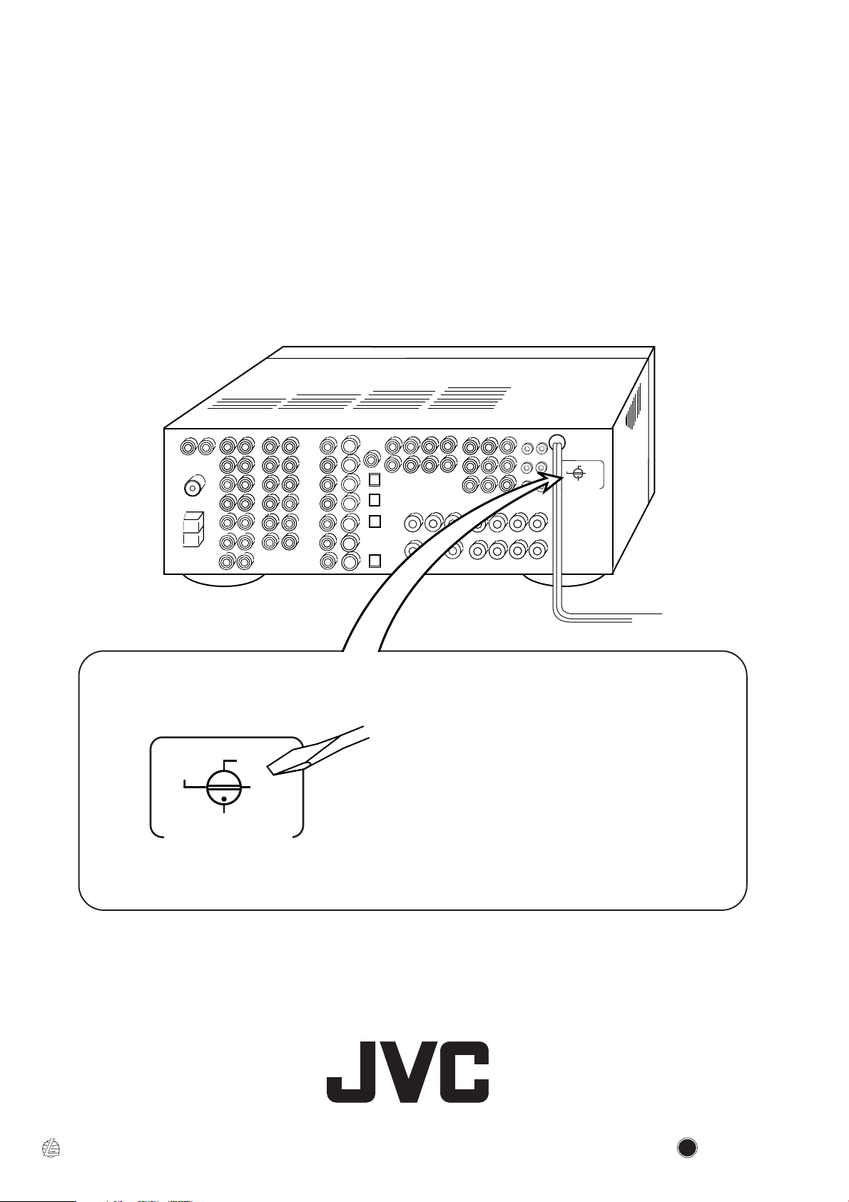
JVC
Mains (AC) Line Instruction (not applicable for Europe, U.S.A., Canada, Australia
and U.K.)
110V
220V
127V
230 - 240V
VOLTAGE SELECTOR
EN
220V
110V
127V
230 - 240V
VOLTAGE SELECTOR
CAUTION for mains (AC) line
BEFORE PLUGGING IN, do check that your mains (AC) line
voltage corresponds with the position of the voltage selector switch
provided on the outside of this equipment and, if different, reset the
voltage selector switch, to prevent from a damage or risk of fire/
electric shock.
VICTOR COMPANY OF JAPAN, LIMITED
0602NHMMDWJEIN
 Loading...