

Page 1
SERVICE MANUAL
AUDIO/VIDEO CONTROL RECEIVER
RX-8020VBK
Area suffix
RX-8020VBK
A/V CONTROL RECEIVER
CATV/DBS VCR1 TV AUDIO
DVD MULTIDVD
CD
CDR
TV/DBS VIDEO PHONO
TAPE/MD
VCR1 VCR 2
SURR/DSP
ANALOG/DIGITAL
DSP
SURROUND
OFF
ANALOG
BASS
DIRECT
BOOST FRONT•L
231
MENU
SOUND
TEST CENTER SUBWFR
564
ENTER
SURR•L SURR•R
DIMMER
7/P
89
SBACK•L SBACK•R
DIGITAL EQ
MUTING
0
10
RETURN FM MODE 100
CATV/DBS
CONTROL
CH/
LEVEL
TV VOL
TV/VIDEO
TEXT
PLAY
MENU
DISPLAY
REC
/REW
PAUSE
PAUSE
SET
DOWN – TUNING – UP
SLEEP
CONTROL
STOP
RM-SRX8020J
REMOTE CONTROL
FM/AM
USB
INPUT
FRONT•R
+10
+
VOLUME
EXIT
FF/
SPEAKERS ON/OFF
SUBWOOFER OUT ON/OFF
PHONES
STANDBY
STANDBY/ON
1
2
FM/AM TUNING FM/AM PRESET FM MODE
SURROUND
Contents
USB AUDIO
PUSH OPEN
DSP
S-VIDEO VIDEO
MEMORY
SURROUND/DSP
OFF
VIDEO
L—AUDIO—R
INPUT
ANALOG/DIGITAL
INPUT ATT
RX-8020V
AUDIO/VIDEO CONTROL RECEIVER
SOURCE NAME
TV SOUND/DBSVIDEOVCR 2VCR 1DVDDVD MULTI
SOUCE NAME
FM/AMUSB AUDIOTAPE/MDCDRCDPHONO
DIGITAL
EQ
EFFECT SETTING
CONTROL
DOWN UP
UJ ---------- U.S.Military
MASTER VOLUME
LEVEL
ADJUST
ANALOG DIRECT
BASS BOOST
Safety precautions --------------------------------------------------------1-2
Disassembly method -----------------------------------------------------1-3
Adjustment method -------------------------------------------------------1-9
Self-diagnose function-----------------------------------------------------1-10
Description of major ICs -------------------------------------------------1-12~31
COPYRIGHT 2002 VICTOR COMPANY OF JAPAN, LTD.
No.21161
Oct. 2002
Page 2
Adjustment method
Tuner section
1.Tuner range
FM 87.5MHz~108.0MHz
AM(MW) 531 kHz to 1 602 kHz (at 9 kHz intervals)
530 kHz to 1 600 kHz (at 10 kHz intervals)
Power amplifier section
Adjustment of idling current
Measurement location B2204-B2205(Lch) , B2213-2214(Rch)
Adjustment part VR787(Lch) , VR788(Rch)
Attention
This adjustment does not obtain a correct adjustment value immediately after the amplifier is
used (state that an internal temperature has risen).
Please adjust, after you turn off amplifier and internal temperature falls.
RX-8020VBK
<Adjustment method>
1.Set the volume control to minimum during this adjustment.(No signal & No load)
2.Set the surround mode OFF.
2.Turn VR787 and VR788 fully counterclockwise to warm up before adjustment.
If the heat sink is already warm from previous use the correct adjustment can not be made.
3.For L-ch,connect a DC voltmeter between B2204 and B2205 (Lch)
And,connect it between B2213 and B2214(Rch).
4.30 minutes later after power on, adjust VR787 for L-ch, or VR788 for R-ch so that the DC voltmeter
value has 1mV~10mV.
* It is not abnormal though the idling current might not become 0mA even if it is finished to turn variable
resistance (VR787,VR788) in the direction of counterclockwise.
Heat sink
Rch amp. board
VR788 (Rch)
Lch amp. board
B2213, B2214
VR787 (Lch)
B2204, B2205
1-9
Page 3
RX-8020VBK
Self-diagnose function
1. Detection of abnormal power supply and voltage
When the power is turned ON, if an abnormality is detected during the signal input at the A/D port (IC901,
pin 2-5, 7) for one second continuously, the status will become STANDBY mode immediately.
When the power is turned ON again, detection of abnormal power supply and voltage will not be carried out
during the first 4 seconds.
Given below is a list of threshold values at the detection of abnormalities.
Pin 2
Micro-computer+5V
Pin 3
Digital+5V
Pin 4
Analog+5V
Pin 5
+12V
Pin 7
Tuner+9V
At abnormal state
(Low voltage)
Analog value
0 - 2.2V
Analog value
0 - 2.2V
Analog value
0 - 2.2V
Analog value
0 - 2.2V
Analog value
0 - 2.2V
At normal state
Analog value
2.2 - 2.8V
Analog value
2.2 - 2.8V
Analog value
2.2 - 2.8V
Analog value
2.2 - 2.8V
Analog value
2.2 - 2.8V
At abnormal state
(High voltage)
Analog value
2.8 - 5.0V
Analog value
2.8 - 5.0V
Analog value
2.8 - 5.0V
Analog value
2.8 - 5.0V
Analog value
2.8 - 5.0V
2. Initial setting on ship
To gain the initial setting on ship, put the power plug in the socket while pressing "DOWN" key and "UP" key
together simultaneously, then turn the power ON.
3. Test mode
To enter the test mode, put the power plug in the socket while pressing "EFFECT" key and "UP" key together
simultaneously, then turn the power ON.
Workings of test mode:
All FLs are turned ON for 3 seconds. (the FLs, which are divided in two groups, are turned ON alternatively)
A Faster volume UP/DOWN operation can be achieved with the remote controller.
When the power is turned OFF, the test mode will be released.
The FL display returns to normal after the three seconds. Then the STANDBY LED is turned ON (flashing
ON and OFF for each one second) to show the present status being a test mode.
1-10
Page 4
RX-8020VBK
4. Self-diagnose
To enter the self-diagnose mode, put the power plug in the socket while pressing "SETTING" key and "UP" key
together simultaneously, then turn the power ON.
While the working status is being displayed, the each item can be switched with the UP/DOWN key
operation.
When the power is turned OFF, the self-diagnose mode will be released.
During the self-diagnose mode, the STANDBY LED is turned ON (flashing ON for one second then OFF for
three seconds).
FL transient display will be carried out as follows. When the transient display is not carried out,
normal display/workings are carried out.
S0001
200202209
V
D1
D2
D3
D4
D5
D6
D7
e
r
0
2
/
0
D
S
P
R
A
N
A
D
D
D
D
D
D
U
F
F
F
F
N
G
U
N
P
C
A
C
A
C
D
D
D
A
A
M
P
N
G
U
N
1
2
2
2
3
2
3
2
3
N
G
L
I
G
I
I
G
I
I
G
I
I
G
I
I
G
I
I
G
I
N
L
O
s
3
s
4
s
4
s
9
D
L
O
M
3
3
T
T
T
S
S
S
-
C
E
G
D
L
O
/
0
.
/
0
.
/
0
.
/
0
.
/
0
.
/
1
.
/
1
.
/
2
.
/
2
.
D
Information on VERSION of system microcomputer (IC901)
Example : 2002/2/20 9th ROM
1
.
0
Display the local version (IC581)
0
Example : Ver_1.00
2
/
1
Display the local creation date
0
Example : 2002/2/10
e
v
4
Display the DSP version (IC511)
1
Example : DSP Rev41
O
G
x
T
A
L
T
A
L
T
A
L
T
A
L
T
A
L
T
A
L
C
2
4
8
6
A
C
E
E
E
A
C
0
0
0
0
0
0
0
0
0
A
K
H
k
H
k
H
k
H
k
T
A
K
X
S
S
A
T
K
L
D
T
A
Display the input sources
x
1
However, since it is the source of DIR processing, actual source may be
2
3
contradicted.
4
Example : ANALOG08
5
Display the input Fs
z
Example : Fs48kHz
z
z
z
Display the input format
Example : PCM
M
D
Display the input channel
Example : 2/0.0
t
M
1-11
Page 5
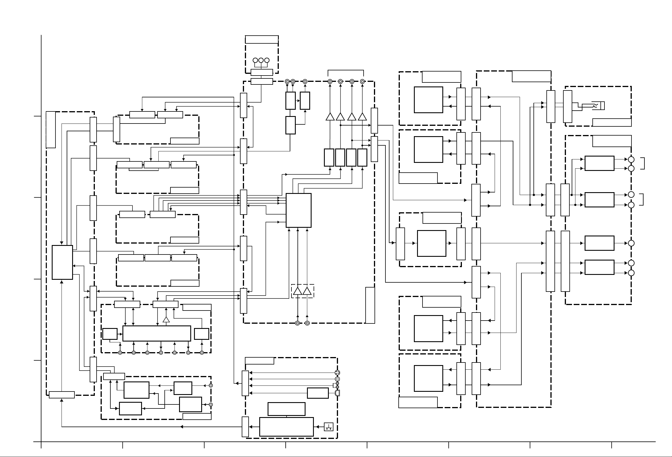
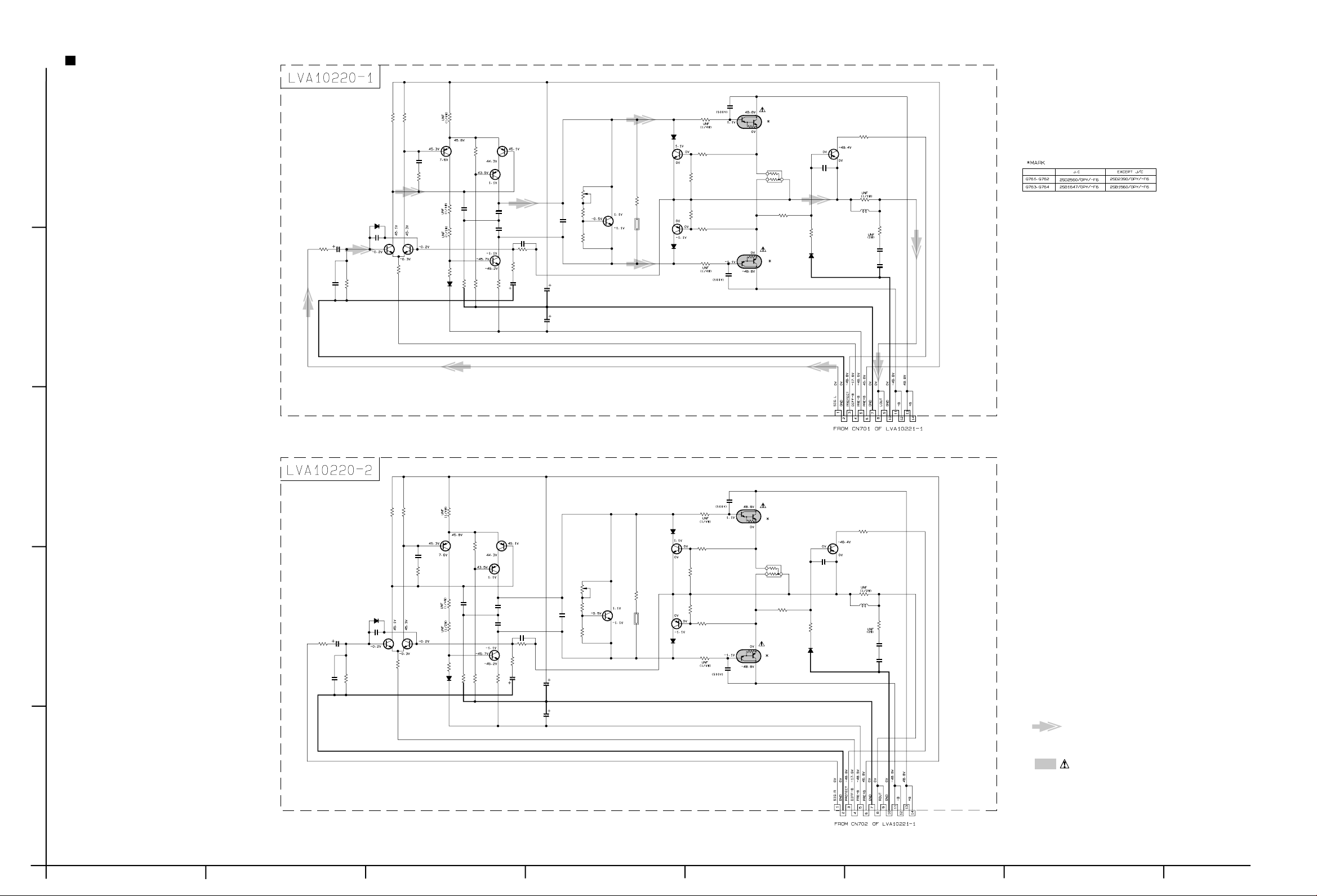
Block diagrams
5
LVA10336-6
COMPU LINK
TEXT LINK
CN393
CN392
RX-8020VBK
7.1ch
Preout
STB
Monitor out
LVA10220-1
LVA10221-1
DVD
FRONT Y/C
CN244
TEXT
DATA
(Refer to the following page.)
CN240
S video
LVA10338-1
4
Vido5, 6
CN200 CN204 CN206
Vido5, 6
(Refer to the following page.)
CN242
TEXT
LVA10336-5
FRONT VIDEO
Video
LVA10336-4
DSP CLK
C
RL/RR
CN587 CN581
SBL/SBR
L/R
AUDIO
TEXT
CN243
CN501 CN205
MONI
Vido5, 6
AUDIO
IC389IC388
SBL/SBR
IC390
SW
IC380
SBL/SBR
IC399
IC384
L/R
IC396
IC381
L/R
C/W
IC397
IC382
C
RL/RR
IC398
IC383
RL/RR
L/R
CN731CN732
C
Lch
Rch
RL/RR
LVA10220-2
Q761
Q763
Q762
Q764
LVA10220-3
CN711
CN712
CN701
CN702
R
L
CN721
CN881
FW881
LVA10338-7
LVA10221-2
RY831
L
RY832
CN813
CN823
R
L
SPK1
R
L
SPK2
R
DSP
(Refer to the following page.)
3
DATA
CN313 CN371 CN416
CPU
IC901
CLK,DAT
MAIN_STK,
Video audio
(Refer to the following page.)
V SIG
LVA10337
LVA10336-3
FRONT AUDIO
CN381
V SIG
AUDIO
DVD CENTER
DVD REAR
DVD SUB WOOFER
IC386
Cch
CN722
Q1751
Q1752
CN713
CN703
RR
RL
CN723
C
RL
CN824
RR
CN814
RY851
RY852
CENTER
REAR L
REAR R
2
CN400
DATA
TUNER
IC 301
CN101 CN301 CN303 CN601 CN201 CN241
1
CN311 CN351
TUNER
MAIN_STK,
EQ
PHONO
CN111
TUNER
DATA
SOURCE SELECTOR
CD
L/R
L/R
AM/FM DET
IC102
PLL
IC121
V SIG
IC 302
P.B
TAPE
AUDIO
REC
TAPE
CLK,DAT
IC 303
CDR
TUNER
RF 101
P.B
LVA10336-2
DVD REAR
IC 304
REC
CDR
MW RF
& OSC
T111
DVD
REAR
FM
AM
CN361
LVA10218-1
CN406
Y/C
VIDEO
AUDIO
USB
FL DISPLAY
DI400
DVD
CENTER
DVD
SUB WOOFER
USB DAC
IC 410
LVA10336-1
RLch
RRch
LVA10221-5
LVA10220-4
Q1851
Q1853
Q1852
Q1854
CN715
CN716
CN705
CN706
LVA10009
SYSTEM CONTROLLER
CN410
ABCD E F G
IC 400
KEY
2-1
Page 6

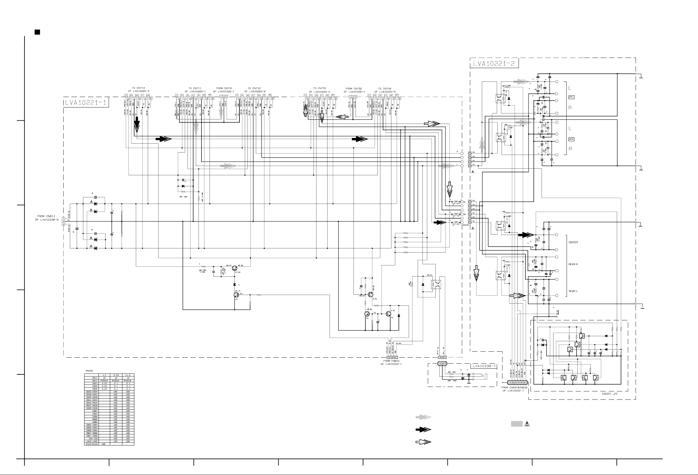
Standard schematic diagrams
Power supply section
RX-8020VBK
Power trans1 board
Power trans2 board
Power/fuse board
5
PW20
PW17PW27
PW26
PW18
PW19
PW30
F1
TA1
TA2
T2
QQT0281-004
D52
11ES2-T4
11ES2-T4
15k
PW10
PW11
PW12
PW13
PW14
PW15
PW16
D57
1SS133
R53
R52
6.8
3.3k
MTZ12JC
C1
0.0047
RY1
QSK0098-001
Q51
2SD2395/EF/
C53
0.0047
D55
PW21
PW22
PW23
PW24
PW25
R54
820
C54
470/16
Q53
KRC105M
KTD863/Y/
C55
Q52D53
0.0047
D56
MTZ6.2JB
F4
VS1
QSW0812-001
PW28
PW29
PW40
131
132
CN811
Power supply board
4
Sheet 2/10
R61
F61
F62
8.2
113
112
111
123
122
121
134
133
Sheet 9/10
CN55
CN402
C69
0.047MY
C68
0.047MY
3
Sheet 3/10
2
Relay board
CN82
CN72
CN71
R74
100k
C74
1/50
D75
MTZ8.2JC
Q74
KTC3200/GL/
R73 D74 C72
KTA1046/Y/
C73
22k
Q71
22/50
MTZ33JC
CN56
FW51
D61
10E2-FD
D63
10E2-FD
C65 C66
3300/35 1000/35
D73
11ES2-T4
3.3k
R72
C71
22/50
100/63
11ES2-T4
D62
C63
0.1MY
C70
220/50
D71
11ES2-T4
D72
11ES2-T4
C62C61
0.1MY0.1MY
D64
11ES2-T4
TH71
QAD0095-4R7
D51
11ES2-T4
C51
0.0047/100
11ES2-T4
C52
470/63
F2
D54
R51
EP51
SHEET
NUMBER
1/10
1
2/10
3/10
4/10
5/10
6/10
7/10
8/10
9/10
10/10
POWER SUPPLY
MAIN
AUDIO
AUDIO SIGNAL / VIDEO SIGNAL INPUT
DVD
AUDIO AMP (FRONT CHANNEL)
AUDIO AMP (CENTER, REAR CHANNEL)
DSP
SYSTEM CONTROL
TUNER
ABCD E F G
CIRCUIT DESCRIPTION
Parts are safety assurance parts.
When replacing those parts make
sure to use the specified one.
SHEET 1/10
2-3
Page 7
4
3
2
5
Main & Speaker terminal section
Sheet 7/10 Sheet 7/10 Sheet 7/10Sheet 6/10 Sheet 6/10Sheet 5/10 Sheet 5/10
Sheet 1/10
Main board
CN801
C805
C801
D801
30DF2-FC
D803
30DF2-FC
C802
D802
30DF2-FC
D804
30DF2-FC
CN703
C807C808
R801R802
100k100k
6800/716800/71
CN701
MTZ18JC
RX-8020VBK RX-8020VBK
Speaker board
C845
C833
220p
R831
12
RY851
FW931
D831
1SS133
R832
12
1SS133
D832
R851
12
1SS133
D851
C885
0.047
R852
12
1SS133
D852
R888
0.047
0.047
R887
CN721
C816
47/25
D816
R816
3.3k
12
R815
Q811
3.3k
R812
Q812
KTC3200/GL/
2SD2395/EF/
D811
R814
10k
47k
R813
R811
C811
0.0047
CN702
CN705
CN723
10/25
C824
R826
Q825
KTA1268/GL/
10k
R825
R823
100k
130k
R824
Q824
KTC3200/GL/
10k
47/16
Q823
KTC3199/GL/
C823
Sheet 3/10
CN831
R841
R842
R843
R844
R845
1SS133
D825
CN706
CN813
0.45
L844
B124
0.45
L845
B125
0.45
L843
100k
82k
100k
100k
82k
12
R871
D871
1SS133
RY871
QSK0109-001
CN881
Headphone jack board
FW881
R91
R92
CN824
B123
CN814
470
C91
C92
470p470p
470
RY831
RY832
CN823
RY852
J91
0.022
R833
10
C835
0.022
C834
0.022
220p 220p
C836
0.022
10
C842 C841
R834
C846
220p
C847
220p
1010
R837R838
C837
0.022
C839
C838
0.022 0.022
C848
220p
C891
220p
220p
R885
10
C886
220p
10
C888
C890
C892
220p
C887
220p
10
C889
C893
220p
C850
4.7/50
D841
MTZ5.1JC
R855
3.9k
D845
1SS133
D846
1SS133
R867
10k
220p220p
C843C844
C883
330p
C881
330p
C884
330p
C840
0.022
S831
Q833
KRC109M
Q830
KRC109M
R865
4.7k
ST831
ST851
22k
C851
4.7/504.7/504.7/50
Q835
KRC109M
D843
1SS133
D844
1SS133
D842
1SS133
22k
22k
R862
R856
R859
6.8k
R857
6.8k
6.8k
R860
R863
R864
4.7k
Q831
KRC109M
R861
R858
4.7k
4.7k
Q832
KRC109M
C852
C853
R866
4.7k
Q836
Q834
KRC109M
KRC109M
Sheet 3/10
1
FRONT Signal
Parts are safety assurance parts.
CENTER Signal
When replacing those parts make
sure to use the specified one.
REAR Signal
SHEET 2/10
2-4
HABC DEFG
Page 8
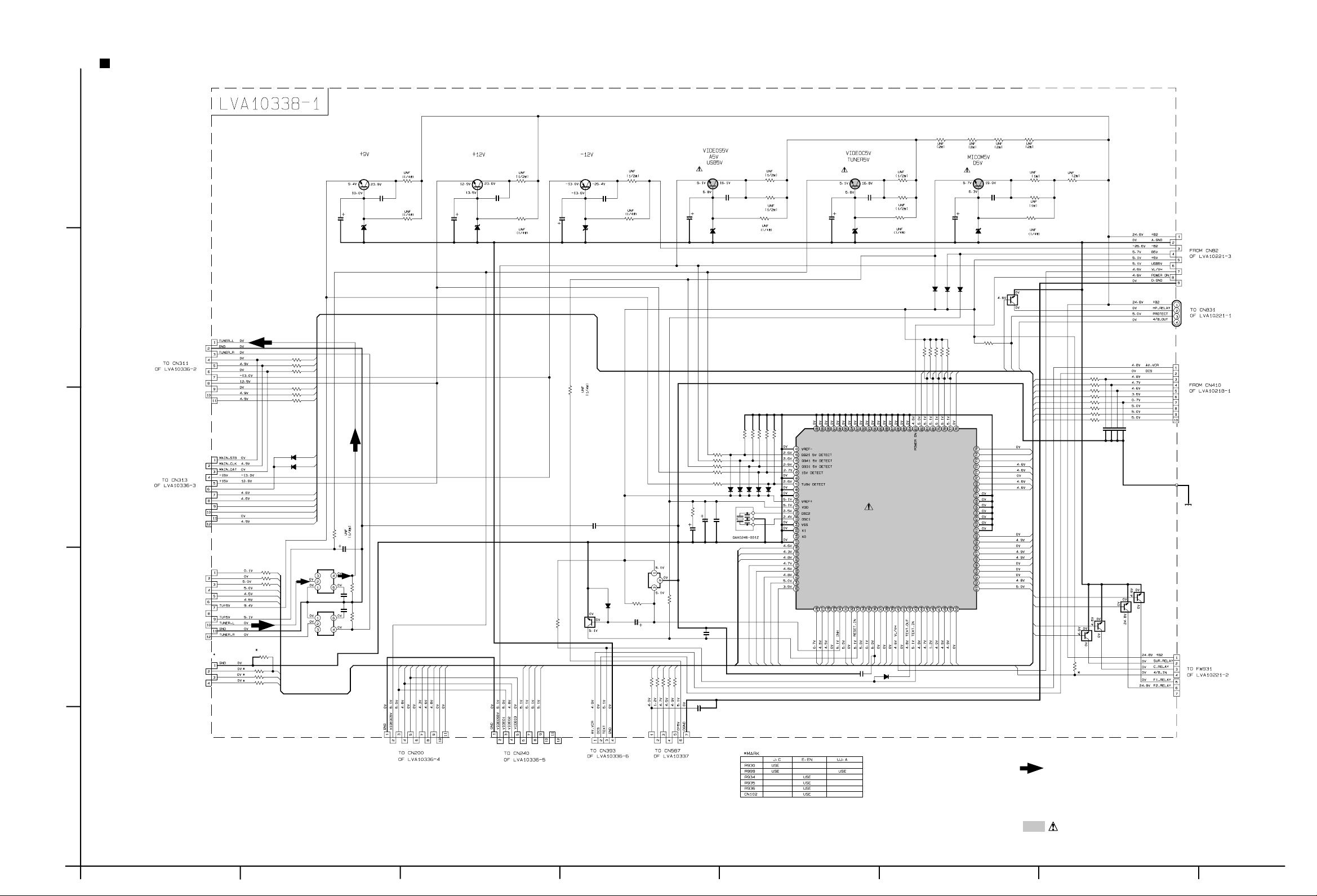
Audio section
RX-8020VBK
Audio board
R916
R915
3.9
3.9
C972
0.0047
D971
MTZ10JC
R971
R973
12
3.3k
Q951
2SD2395/EF/
C951
100/25
D951 D961
MTZ13JC
5
2SD2395/EF/
C971
100/25
Q971
0.0047
C952
R953
R951
2.2k
12
C961
100/25
Q961
KTA1046/Y/
MTZ13JC
0.0047
C962
R963
2.2k
R961
R943
R941
R942
12
12
C921
2.7k
100/25
D921
MTZ5.6JC
Q921
2SD2395/EF/
12
2SD2395/EF/
C941
100/25
D941
MTZ5.6JC
Q941
0.0047
C942
C922
0.0047
R921
R923
2.7k
R922
12
12
470/16
C931
D931
MTZ6.2JC
Q931
2SD2395/EF/
0.0047
C932
R914
R913
3.9
3.9
R933
2.7k
R932
R931
33
33
R918
18
Sheet 1/10
D902
11ES2-T4
D901
11ES2-T4
D900
11ES2-T4
Q908
KRC105M
CN81
4
FW831
CN301
10k
10k
10k
10k
4/8_OUT
10k
R965
R966
R967
DVD_S/C
VCR1_S/C
STANDBY_LED
DSPRESET
DSPSTATUS
DSPCOMMAND
R968
VCR2_S/C
DSPCLK
R969
DBS_S/C
DSPREADY
MAIN_STB
MAIN_CLK
MAIN_DAT
-15V
CN303
+15V
VOL_STB
VOL_CLK
VOL_DAT
Sheet 4/10
3
FR_RELAY
C_RELAY
Sheet 4/10
To CN111
2
Sheet 10/10
To CN112
Sheet 10/10
SUR_RELAY
SrBL_MUTE
SrBR_MUTE
S_MUTE
SW_MUTE
CN101
TUNER_DATA
TUNER_CE
TUNER_CK
TUNER_MUTE
TUNED
STEREO
CN102
RDS_ST
RDS_DATA
RDS_CLK
R936
R935
R934
R938
R939
R937
R999
R944
220
R945
220
R946
220
R954
220
R955
220
R956
220
1SS133-T2
F1_RELAY
D955
F2_RELAY
D956
1SS133-T2
22
R975
C975
470/6.3
FL991
220
220
220
10k
220
220
220
QQR0590-001
FL992
QQR0590-001
C991
0.0056
C992
0.0056
R991
R992
4.7k
4.7k
VIDEO1
VIDEO2
CN201
VIDEO3
VIDEO4
OSD_CS
OSD_DAT
OSD_CLK
VIDEO5
VIDEO6
CN241
DVD_S/C
DBS_S/C
VCR1_S/C
VCR2_S/C
R908
3.3
R940
4.7k
4.7k
5.1k
3.3k
5.6k
R994
R996
R998
R979
0.022
R977
4.7k
4.7k
6.2k
13k
15k
D975
1.5
C902
X901
D976
1SS133-T2
8MHz
D977
D978
D979
OSD_DAT
OSD_CS
OSD_CLK
M_COMMAND
M_STATUS
M_CLK
M_RESET
M_CS
M_BUSY
TUNED
STEREO
RDS_ST
MN101C49GJY
TUNER_CK
PROTECT
4/8_IN
TUNER_MUTE
TUNER_DATA
C993
100p
IC901
TUNER_CE
RDS_DATA
D993
1SS133-T2
RDS_CLK
R976
R978
R993
R995
R997
330
R903
100/6.3
C985
0.01
IC903
IC-PST9139
22k
220
220
R925
R926
DSPCLK
DSPSTATUS
R910
220
220
220
R927
R928
R929
DSPREADY
DSPRESET
DSPCOMMAND
D904
R911
1SS133-T2
4.7k
Q901
22k
KRC107M
CN933
C904
2.2/50
CN601
C903
C994
270P
2200/6.3
C901
C905
VIDEO6
VIDEO_S/C
S_MUTE
SW_MUTE
R924
10k
MAIN_DAT
MAIN_CLK
MAIN_STB
VOL_DAT
VOL_CLK
VOL_STB
VIDEO4
VIDEO3
VIDEO2
VIDEO1
HP_RELAY
VIDEO5
SrBR_MUTE
SrBL_MUTE
SUR_RELAY
C_RELAY
F2_RELAY
F1_RELAY
HP_RELAY
SUR_RELAY
4/8_OUT
PROTECT
F1_RELAY
F2_RELAY
C_RELAY
4/8_IN
R930
R980
R981
R982
R983
R984
R985
R986
R987
10k
Q907
KRC105M
220
220
220
220
220
220
220
220
Q906
C981
C982
330p
KRC105M
M_CLK
M_COMMAND
M_STATUS
M_CS
M_BUSY
M_RESET
STANDBY_LED
VCR_S/C
330p
C984
C983
330p
330p
Q903
Q904
KRC105M
KRC105M
Sheet 2/10
CN400
Sheet 9/10
EP901
CN931
Sheet 2/10
CN932
Sheet 4/10 Sheet 4/10 Sheet 8/10Sheet 5/10
TUNER Signal
1
Parts are safety assurance parts.
When replacing those parts make
sure to use the specified one.
ABCD E F G
SHEET 3/10
2-5
Page 9

RX-8020VBK RX-8020VBK
Audio / Video Audio / Video / S video signal input section
CN200
Audio input board
C301
R301
2.2k
4.7/50
CDR.PLAY-R
100k100k
CD-R
REC-R
PLAY-R
CDR.REC-R
C302
R302
2.2k
4.7/50
J301
QNN0056-001
J302
QNN0056-001
J303
QNN0058-001
5
C333
C321 C322
220p
C323 C324
220p
C325 C326
220p
C327 C328
220p
C329 C330
220p
C331 C332
220p
100k100k
IC304
BA15218F-XE
IC304
BA15218F-XE
C334
R334
220p
R324
470
220p
R326
470
220p
R328
470
220p
R330
470
220p
R332
470
220p
C363
4.7/50
R365R366
C364
4.7/50
R333
470 470
R323
CD-L
470
R325
REC-L
470
R327
PLAY-L
470
R329
CDR.REC-L
470
R331
CDR.PLAY-L
4
470
C361
4.7/50
100k100k
R363R364
R361R362
C362
4.7/50
R305
C309C310
47k47k
100p100p
C303C304
R303R304
100p100p
620
100/10
C314 C313
100/10
R306
620
R335
68
C335
22/25
IC302
TC9164AF-X
C336
22/25
R336
68
QGB1214K1-14S
NJM4580D-D
CN351
IC301
IC301
NJM4580D-D
CD-R
CD-L
V.SIG.R
V.SIG.L
C305
0.0018 0.0068
R307
C306
0.0018 0.0068
39k 470k
R308
PLAY-R
CDR.PLAY-R
CDR.PLAY-L
PLAY-L
DVD_RS
DVD-LS
39k 470k
R310
TUNER-R
V.SIG.R
V.SIG.L
TUNER-L
C307
R309
C308
VOL_STB
VOL_CLK
VOL_DATA
REC-R
REC-L
C311
4.7/50
C312
4.7/50
100k100k
CDR.REC-R
CDR.REC-L
Sheet 5/10
3
Video audio board S video board
R371
R373
TV/DBS-L
R375
VCR1.REC-L
R377
VCR1.PLAY-L
R379
VCR2.REC-L
R381
VCR2.PLAY-L
470
470
470
470
470
C371 C372
220p 220p
C373 C374
220p
C375 C376
220p
C377 C378
220p
C379 C380
220p
C381 C382
220p
R372
470470
DVD.F-RDVD.F-L
R374
470
J371
TV/DBS-R
220p
R376
220p
R378
220p
R380
220p
R382
220p
470
VCR1.REC-R
470
VCR1.PLAY-R
470
VCR2.REC-R
470
VCR2.PLAY-R
QNN0056-001
J372
QNN0056-001
J373
QNN0056-001
2
68
R385
DVD.F-R
TV/DBS-R
TV/DBS-L
USB-L USB-R
VCR1.PLAY-R
VCR1.PLAY-L
C385
R393
C393
R391
5.1k
0.0012
0.0012
C395
10k
120p
R395
5.1k
C394
R396R392
5.1k
5.1k
C396
R394
120p
10k
IC372
BA15218F-XE
IC372
BA15218F-XE
C397
USB-L
10/50
R397
100k
R398
100k
USB-R
C398
10/50
C391
10/50
C392
10/50
22/25
IC371
TC9163AF-X
C386
22/25
68
R386
DVD.F-L
VIDEO-L
VIDEO-R
470
470
R387
R388
R390
470
R389
470
VCR2.PLAY-R
VIDEO-R
VIDEO-L
VCR2.PLAY-L
VCR1.REC-R
VCR2.REC-R
VCR2.REC-L
VCR1.REC-L
V.SIG.R
V.SIG.L
C389
560p
R315
330
47/1647/16
C315
R311
R200
R312
R316
C316
330
IC303
BA15218F-XE
C341
10/50
R343
100k100k
R341R342
R344
C342
10/50
BA15218F-XE
C339
560p
TUNER-R
TUNER-L
CN311
QGB2510K1-11
IC303
100k100k
VOL_CLK
VOL_STB
VOL_DATA
C343
10/50
100k 100k
R346 R345
C344
10/50
J201J202
QNN0078-001QNN0011-001
J203
QNN0011-001
75
R201
R202
75
R203
75
R204
75
R205
75
R206
75
C226
47p
Sheet 3/10
C269
47P
J242 J241
J243
QND0098-001 QND0097-001
QND0099-001
C268
C276
47p
C275
47p
C271
100p
C270
100p
1
FR.RELAY
SUR.RELAY
V.SIG.L
C.RELAY
SUR.RELAY
SrBL.MUTE
CN416 CN313
QGA2501F1-06 QGB2510K1-12
QGB1214K1-12S
CN371
V.SIG.R
FR.RELAY
SrBR.MUTE
S.MUTE
SW.MUTE
C.RELAY
SrBL.MUTE
SrBR.MUTE
S.MUTE
SW.MUTE
75
47p
R268
75
R209
47k
R211
R213
757575 757575
R240R242
R241R243
C246
0.047
R266
75
R245
R246
C273
0.047
R274
75
7575
R275R276
C252
470/6.3
Video board
C201
R207
330
4.7/50
C202
R208
330
4.7/50
C203
470/6.3
C204
R210
330
4.7/50
C205
470/6.3
47k
C206
R212
330
4.7/50
C207
470/6.3
47k
47P
C280
47P
C281
C242
4.7/50
47P
C282
47P
C245
C283C284C285
4.7/50
R244
75
R267
47k
C247
470/6.3
47P47P
C250
4.7/50
R272
75
R273
47k
C274
470/6.3
47P
C286
47P
C277
C287
4.7/50
C251
R247
75
0.047
R269
47k
150
R214
Q200
KTA1267/YG/-T
Q201
KTA1267/YG/-T
C208
47/16
C209
0.01
IC201
BA7625
IN1
MOUT
A
VOUT1
IN5
IN4
VOUT2
IN3
D
150
R215
R216
300
Q202
KRC110M-T
Sheet 9/10
R253
R254
R255
KRC107M-T
15k
15k
15k
C241
C211
4.7/50
C212
100
150
180
1SS355-X
1SS355-X
R219
D200
D201
Q204
KTA1267/YG/-T
10k
R217
Q203
C210
4.7/50
330
R218
CN206
VIDEO
QGA2501F1-02
R220
R221
Q205
KTA1267/YG/-T
47
R232
Q206
KTA1267/YG/-T
Q208
CN204
QGB1214K1-08S
DTC123YSA-T
IC202
NJM2285V-W
IN1B
OUT1
IN2B
OUT2
OUT3
CTL3
IN3A
IN3B
47/16
C213
0.01
C219
15p
X200
C220
10p
R231
2.2k
C231
4.7/50
Q207
KTA1267/YG/-T
4.7/50
C215
C214
4.7/50
0.047
C216
C217
C218
1.547p
470/10
IC203
MB90088PF-131
YOUT
VOUT
COUT
SIN
SCLK
XD
EXD
L200
22u
27p
0.001
C221
C223
C222
Sheet 5/10
0.047
180
180
R250
C244
0.047
C249
0.047
C272
0.047
4.7/50
0.047
C254
C255
C253
10p
CN244
VIDEOY
VIDE0C
QGA2501F1-04
Q240
KTA1267/YG/-T
IC242
Q241
KTA1267/YG/-T
IC241
R248
R249
BA7626
BA7625
KTA1267/YG/-T
150
R251
Q242
KTA1267/YG/-T
Q244
KRC107M-T
0.01
C256
300
300
R280
R284
C258
300
150
300
R281
R285
Q245
KRC110M-T
Q243
10k
R282
Q246
KRC110M-T
1SS355-X
4.7/50
0.047
C261
Q247
KRC107M-T
D240
D241
1SS355-X
R271
3.3
C260
CN242
QGB1214K1-10S
C257
47/16
0.01
C259
47/16
10k
R283
QGB2510K1-11
R225
2.2
OSDCS
OSDDATA
OSDCLK
Sheet 3/10
560
560
560
R222
R223
R224
270p
120p
C224
C225
CN240
QGB2510K1-12
Sheet 3/10
Parts are safety assurance parts.
When replacing those parts make
sure to use the specified one.
Sheet 5/10
Sheet 3/10Sheet 9/10
Sheet 9/10 Sheet 5/10
AUDIO Signal TUNER Signal PHONO Signal
2-6
VIDEO AUDIO Signal
SHEET 4/10
HABC DEFG
Page 10
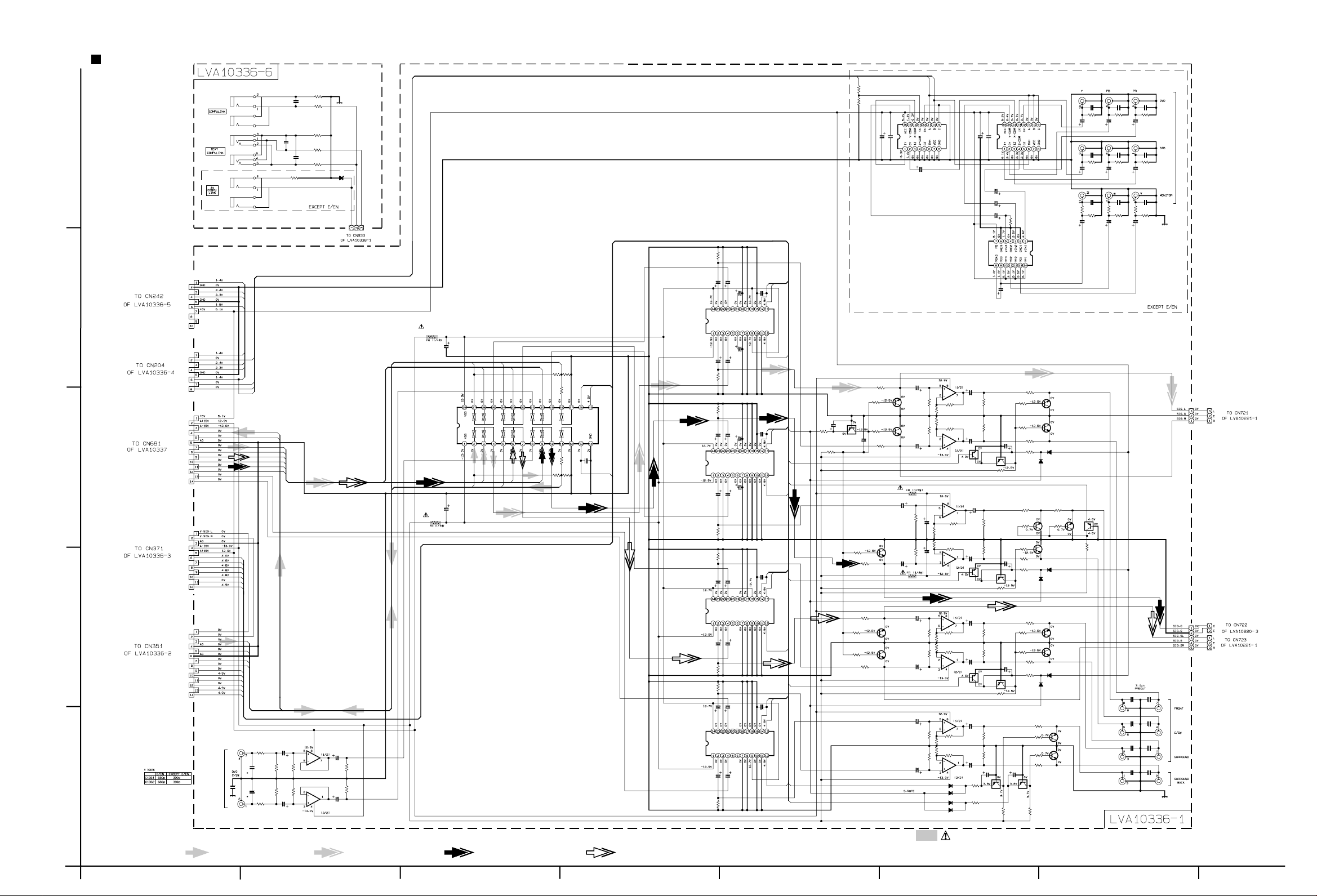
RX-8020VBK
DVD section
Compulink board
R1350
220p
C1352
C1350
470
R1351
220
220p
R1352
100
R1353
220
220p
220
R1354
220
D1350
MA3062/H/-X
CN393
QGA2501F1-03
AV_VCR
DCS
TEXT
J1350
QNS0089-001
J1351
QNS0077-001
C1351
5
J1352
QNS0089-001
R1355
Sheet 3/10
R1312
100k
CN243
QGB1214J1-10S
Yin
Cin
Cmoni
4
Sheet 4/10
Sheet 4/10
3
Sheet 8/10
Sheet 4/10
Ymoni
CN205
QGB1214J1-08S
Yin
YOSD
Cin
Cmoni
Ymoni
VIDEO5
VIDEO6
CN501
QGB1214J1-14S
DSP_IN_L
DSP_IN_R
DSP.L
DSP.R
DSP.LS
DSP.RS
DSP.C
DSP.SW
DSP.SrBL
DSP.SrBR
CN381
QGB1214J1-12S
FR.RELAY
C.RELAY
SUR.RELAY
SrBL.MUTE
SrBR.MUTE
S.MUTE
SW.MUTE
R1301
68
R1302
68
IC380
TC9162AF-X
C1301
47/25
C1302
47/25
FRONT-RFRONT-L
DSP.R
DSP.L
DVD-LS DVD-RS
DSP.RS
DSP.LS
DSP.SW
DSP.C
R1306
R1304
R1305
2.2k
1.2k
1.2k
R1303
2.2k
2.7k
R1308
DSP_IN_R
DSP_IN_L
2.7k
R1307
DATA
STB
IC381
TC9459F-X
CLK
C1303
220p
IC382
TC9459F-X
R1322
R1321
R1332
4.7/50
4.7/50
4.7/50
C1313 C1314
R1311
100k
100k
C1324C1323
4.7/50
4.7/50
100k
100k
C1334
4.7/50
C1311
C1322
C1321
C1332
4.7/50
4.7/50
4.7/50
4.7/50
C1316C1326
C1315
C1325
0.22/500.22/500.22/50
0.22/50
C1319
220p
C1329
C1339
220p
VOL_STB
VOL_DATA
VOL_STB
VOL_DATA
VOL_CLK
VOL_CLK
S.MUTE
R1310
1k
R1309
YOSD
1k1k
R1371R1372
0.01
47/25
TC74HC4053AF-X
C1371
C1372
IC388
R1313
1k
R1315
10k
Q1313
2SC3576-JVC-T
2SC3576-JVC-T
R1324
Q1314
R1316
10k
R1314
1k
4.7/50
Q1324
2SC3576-JVC-T
1k
C1432
10/50
C1310
22/16
Q1310
KRA104S-X
C1309
10/50
470k
R1326
10k
C1431
R1439
R1440
R1431
R1432
C1411
10/50
C1412
10/50
VIDEO6
VIDEO5
C1381 C1382 C1383
47p 47p 47p
R1385
75
C1384 C1385 C1386
Q1421
2SC3576-JVC-T
Q1422
2SC3576-JVC-T220p
D1428
1SS355-X
R1446
10k
D1448
1SS355-X
47/25 4.7/50 4.7/50
C1387 C1388 C1389
47p 47p 47p
R1388
75
C1390 C1391 C1392
47/25 4.7/50 4.7/50
C1393
100p
75
R1391
R1392
R1394
47k
C1396 C1397
470/6.3 100/10
Q1447
KRA104S-X
Q1445
2SC3576-JVC-T
470k
R1447
0.01
47/25
TC74HC4053AF-X
C1374
C1373
IC389
C1370
47/25
C1379
22/25
C1377
22/25
C1375
22/25
1M
R1373
IC390
NJM2580M-X
C1376
22/16
IC396
BA15218F-XE
C1413
R1413R1414
1.2k1.2k
FR.RELAY
1.2k
1.2k
R1415
5.1k
R1416
5.1k
R1436
5.1k
C.RELAY
IC396
BA15218F-XE
KRC107S-X
IC397
BA15218F-XE
R1435
9.1k
IC397
BA15218F-XE
KRC107S-X
Q1428
Q1448
10/50
C1414
10/50
SW.MUTE
C1434
10/50
R1417R1418
Q1429
KRA104S-X
C1433
4.7/50
R1437
R1438
Q1449
KRA104S-X
100k100k
R1429
100k
100k
R1449
100k
R1411
100k
R1412
68
100k
C1439
47/25
R1433
R1434
100k
C1440
47/25
68
R1423
10k
R1424
10k
C1428
22/16
470k
R1441 R1445
R1443
R1444
C1448
R1442
22/16
R1448
470k
R1421
1k
R1422
1k
R1428
1k
D1429
1SS355-X
470 470
Q1441
10k
2SC3576-JVC-T
10k
Q1442
2SC3576-JVC-T
1k
1k
D1449
1SS355-X
C1394 C1395
100p 100p
75
R1393
R1395
47k
100/10
C1398
R1387R1386
7575
J1380
R1390R1389
75
R1396
QNN0391-001
7575
47k
CN731
QJP001-032301
Sheet 2/10
2
Sheet 4/10
1
CN361
QGB1214J1-14S
V.SIG.L
V.SIG.R
FRONT-L
FRONT-R
DVD-LS
DVD-RS
STB
CLK
DATA
VOL_STB
VOL_CLK
VOL_DATA
J1360
QNN0483-001
C1360
AUDIO Signal
R1365R1366
IC386
BA15218F-XE
C1365
DVD-C
IC386
BA15218F-XE
4.7/50
C1366
4.7/50
R1367R1368
100k
100k
DVD-SW
100k100k
R1361
C1363
560
4.7/50
R1363R1364
C1361
100k100k
0.022
C1362
C1364
R1362
560
4.7/50
FRONT Signal CENTER Signal REAR Signal
IC383
TC9459F-X
IC384
TC9459F-X
R1342R1341
VOL_STB
VOL_DATA
VOL_CLK
C1331
C1333
4.7/50
4.7/50
R1331
100k
100k100k
4.7/50
C1344
C1343
4.7/50
C1342 C1312C1341
4.7/50
4.7/50
C1349
220p
VOL_STB
VOL_DATA
VOL_CLK
R1333
R1335
R1336
1k
10k
10k
R1334
1k
Q1333
2SC3576-JVC-T
Q1334
2SC3576-JVC-T
C1451
10/50
C1452
10/50
10/50
C1472
10/50
SrBL.MUTE
SrBR.MUTE
C1471
ABCD E F G
IC398
BA15218F-XE
C1453
R1451R1452
R1471
R1472
100k100k
100k
100k
R1453R1454R1473R1474
1SS355-X
1SS355-X
1SS355-X
1SS355-X
R1455
5.1k
1.2k1.2k1.2k1.2k
R1456
5.1k
SUR.RELAY
R1475
5.1k
R1476
5.1k
D1486
D1488
D1487
D1489
IC398
BA15218F-XE
Q1468
KRC107S-X
IC399
BA15218F-XE
IC399
BA15218F-XE
C1454
10/50
C1474
10/50
R1486
R1487
1k
1k
10/50
C1473
10/50
R1457R1458
KRA104S-X
R1477
R1478
KRA104S-X
Q1469
C1486
22/16
R1469
100k100k
100k100k
Q1486
C1468
22/16
470k
C1487
22/16
KRA104S-X
470k
R1488
Q1487
R1463
10k
R1464
10k
Parts are safety assurance parts.
When replacing those parts make
sure to use the specified one.
R1461
R1462
R1468
CN732
Fr-R
SW
Sr-R
SrB-R
J1490
QNN0484-001
J1491
QNN0485-001
WJP0038-001A
1k
Q1461
2SC3576-JVC-T
Q1462
2SC3576-JVC-T
1k
D1468
1SS355-X
1k
D1469
R1483
R1484
R1481
10k
R1482
R1489
1k
10k
1k
470k
1SS355-X
Q1481
2SC3576-JVC-T
Q1482
2SC3576-JVC-T
Fr-L
CENTER
Sr-L
SrB-L
C1491 C1492
330p 330p
C1493
C1494
330p
C1495
330p 330p
C1497 C1498
330p 330p
330p
C1496
Sheet 7/10
Sheet 2/10
DVD board
SHEET 5/10
2-7
Page 11
Audio amp. section (1/2)
RX-8020VBK RX-8020VBK
Lch amp. board
R705
R707
2k
5
D701
1SS133
R701 C701
10/35
2.2k
C703
100p
R703
100k
C705
100P
Q701
2SD2240-BL/AB/
R709
9.1k
2k
0.01
C711
220
R733
Q703
2SC2240-BL/AB/
R721
R717
R719
150
D771
TH783
QAD0012-202
Q771
KTC3200/GL/
Q773
KTA1268/GL/
1SS133
D773
1SS133
Q707
KTA1268/GL/
1.5k
R725
Q705
KTA1268/GL/
Q709
KTA1268/GL/
C713
C717
5.6k
10k
390
R723
390
1SS133
D703
R731
22P( 500V)
C715
33k
R727
68p
68p
C709
10p
R715
100k
R711
620
Q711
KTC3200/GL/
390
C707
100/16
R729
C741
47/100
C719
0.0047MY
VR787
500
R783
620
Q781
2SD637/QR/
R781
390
R789
270
R775
R777
C751
47p
R761
10
R771
390
200
200
R773
390
R763
10
47p
C753
Q761
Q763
R779
0.22( 7W)
R795
R787
Q791
KTA1268/GL/
C795
0.022
1k
15k
R797
D791
1SS133
47k
R791
33
L791
1u
R793
10
C791
0.047
C793
0.047
4
C745
47/100
CN711
Sheet 2/10
3
Rch amp. board
R706
R708
2k
2k
150
R722
Q774
QAD0012-202
1SS133
Q772
KTC3200/GL/
KTA1268/GL/
1SS133
D772
D774
Q708
KTA1268/GL/
1.5K
D704
5.6k
10k
R724
390
1SS133
Q706
KTA1268/GL/
C718
390
R732
R726
22P( 500V)
33k
R728
C716
C714
Q710
KTA1268/GL/
68p
C710
68p
10p
R716
100k
R712
620
Q712
KTC3200/GL/
C708
390
100/16
R730
C742
C746
47/100
47/100
C720
0.0047MY
VR788
500
R784
620
Q782
2SD637/QR/
R782
390
R790
270
TH784
0.01
C712
220
R734
R710
9.1k
R718
Q704
2SC2240-BL/AB/
R720
R704
D702
1SS133
C706
100p
Q702
2SC2240-BL/AB/
2
C702
R702
10/35
2.2k
C704
100p 100k
1
R778
R776
200
200
R772
R774
R762
390
R764
C752
47p
10
390
10
C754
47p
Q762
Q764
R780
0.22( 7W)
R796
R788
R792
47k
33
L792
1u
R794
10
C792
0.047
C794
0.047
Q792
KTA1268/GL/
C796
0.022
1k
15k
R798
D792
1SS133
FRONT Signal
Parts are safety assurance parts.
When replacing those parts make
sure to use the specified one.
CN712
2-8
Sheet 2/10
SHEET 6/10
HABC DEFG
Page 12
5
4
Audio amp. section (2/2)
Cch amp. board
Sheet 5/10
CN722
R1701
RX-8020VBK
R1721
220
R1711
330
100/16
C1704
R1712
56k
C1705
C1713
100/16
Q1703
KTA1268/GL/
C1711
33p
R1722
3.3k
R1723
3.3k
5p
C1712
0.01MY
R1724
3.3k
R1725
3.3k
R1733
TH731
QAD0012-202
C1715
47/50
C1743
47/100
270
Q1731
2SD637/QR/
R1741
R1731
R1732
910390
220
Q1771Q1772
KTC3200/GL/KTA1268/GL/
D1771
1SS133
D1772
1SS133
R1751
R1752
R1773
R1774
10
C1751
10
R1771
390
200
200
R1772
390
Q1752
2SB1560/OPY/-F6
C1752
47p
R1793
R1795
47k
Q1791
KTA1268/GL/
C1791
0.022
18k
R1761
L1761
0.45u
33
R1762
10
C1761
0.047
C1762
0.047
Q1751
2SD2390/OPY/-F6
R1753
0.22
R1791
1k
D1791
1SS133
47p
47/100
CN713
C1741
R1703
2k
D1701
1SS133
C1701
C1703
1/50
2.2k
C1702
Q1701
R1705
Q1702
2SC2240/AB/
12k
2SC2240/AB/
R1702
68k
100p
Sheet 2/10
RLch amp. board
3
R1805
2k
D1801
R1801
1SS133
C1805
C1801
1/50
2.2k
C1803
100p
2SC2240/AB/
R1803
68k
Q1801
R1809
12k
Q1803
2SC2240/AB/
R1811
330
R1813
C1807
100/16
56k
C1809
5p
2
C1815
100/16
C1811
R1821
220
Q1805
KTA1268/GL/
33p
R1823
R1825
C1813
0.01MY
R1835
3.3k
TH831
QAD0012-202
3.3k
C1817
47/50
R1827
3.3k
R1829
3.3k
C1843
47/100
270
Q1831
2SD637/QR/
R1841
R1831R1833
910390
D1871
1SS133
Q1871Q1873
KTC3200/GLKTA1268/GL/
D1873
1SS133
220
R1851
R1853
10
10
R1871
390
R1875
200
R1877
200
R1873
390
2SB1560/OPY/-F6
C1851
Q1853
C1853
47p
C1841
47/100
C1891
0.022
R1893
18k
D1891
1SS133
R1895
47k
Q1891
KTA1268/GL/
R1861
L1861
0.45u
33
R1863
10
C1861
0.047
C1863
0.047
Q1851
2SD2390/OPY/-F6
R1855
0.22
R1891
1k
47p
RRch amp. board
R1802
R1822
C1816
R1806
2k
D1802
1SS133
C1802
C1806
1/50
2.2k
C1804
100p
2SC2240/AB/
R1804
68k
Q1802
R1810
12k
Q1804
2SC2240/AB/
R1814
R1812
330
C1808
100/16
56k
C1810
5p
100/16
C1812
33p
R1824
R1826
220
Q1806
KTA1268/GL/
910
270
C1814
0.01MY
R1836
3.3k
R1828
3.3k
R1830
TH832
QAD0012-202
C1818
47/50
C1844
47/100
Q1832
2SD637/QR/
3.3k
3.3k
D1872
R1832R1834
1SS133
Q1872Q1874
KTC3200/GL
390
KTA1268/GL/
D1874
1SS133
R1842
220
R1854
R1852
10
R1876
200
R1878
200
C1852
47p
R1872
390
R1874
390
Q1854
2SB1560/OPY/-F6
10
C1854
R1894
C1892
0.022
18k
R1896
47k
Q1892
KTA1268/GL/
R1862
L1862
0.45u
33
R1864
10
C1862
0.047
C1864
0.047
Q1852
2SD2390/OPY/-F6
R1856
0.22
R1892
1k
D1892
1SS133
47p
C1842
47/100
CN716
Sheet 2/10
CN715
Sheet 2/10
CENTER Signal
1
REAR Signal
Parts are safety assurance parts.
When replacing those parts make
sure to use the specified one.
SHEET 7/10
ABCD E F G
2-9
Page 13

RX-8020VBK RX-8020VBK
DSP section
C2003
C2011
LINLIN
4.7/25
5
RIN
RIN
C2012
4.7/25
L
R2201
10k
Q2201
2SD1328/ST/-X
R2202
10k
Q2202
2SD1328/ST/-X
R
C2201
C2202
0.0027
R2206
R2205
0.0027
1k
R2003
1k
R2001
100k
R2002
100k
R2004
1k
C2207
4.7/50
1k
C2211
0.001
C2213
100k
33k 33k
C2214
R2207
R2222 R2221
24k
BA15218F-XE
R2223
100k
C2230
R2208
4.7/50
IC522
C2212
C2208
0.001
4.7/50
4
C2307
R2305
2.2/50
2SD1328/ST/-X
Q2302
2SD1328/ST/-X
SL
Q2301
SR
R2301
R2302
1K
10k
C2301
R2307
0.001
100k
C2302
10k
0.001
R2306
R2308
100k
C2308
1k
2.2/50
3
C2407
R2405
10k
10k
R2801
10k
2.2/50
1k
R2407
C2401
0.001
100k
C2127
C2101
0.001
R2105
10k
0.1
100k
R2107
C2107
1k
4.7/25
47k
R2127
C2807
R2805
2.2/50
1K
C2801
R2807
0.001
100k
C2802
R2808
0.001
100k
R2806
C2808
1k
2.2/50
C
R2401
Q2401
2SD1328/ST/-X
R2101
Q2101
2SD1328/ST/-X
SUBWFR
2
Q2801
2SD1328/ST/-X
Q2802
2SD1328/ST/-X
SBL
R2802
SBR
0.0068
R2005
BA15218F-XE
IC521
1k
R2213
1k
BA15218F-XE
C2215
C2216
R2214
1k
1k
R2128
47k
IC527
R2215
0.01
0.01
R2216
C2004
0.0068
1k
1k
C2005
0.1
C2006
0.1
IC521
BA15218F-XE
C2251
0.1
0.1
C2252
BA15218F-XE
IC523
C2238
C2128
0.1
IC523
R2238
C2237
R2237
33p
33k
33k
33p
R2007
R2008
1k
R2235
33k
R2233
33k
R2231
27k
BA15218F-XE
R2232
27k
R2234
33k
R2236
33k
R2353
2.2k
Q2363
2SD1328/ST/-X
Q2364
2SD1328/ST/-X
R2354
2.2k
C2152
R2151
10
2.2k
R2130
C2130
4.7/50
R2129
10
1k
C2351
1/50
R2355
R2356
C2352
1/50
0.1
C2153
0.1
IC528
BA15218F-XE
100k
100k
R2225
R2227
100k
R2226
10k
10k
C2154
0.082
Q2131
2SD1328/ST/-X
C2131
0.082
C2007
0.0027
C2008
0.0027
C2261
4.7/25
R2261
100k
R2262
100k
C2262
4.7/25
IC528
BA15218F-XE
R2131
10k
C2353
R2152
R2357
C2354
R2358
C2155
0.033
C2132
0.033
R2857
C2853
C2854
C2355
C2356
10k
C2855
C2856
R2858
C2283
R2283
C2255
C2009
C2010
4.7/25
C2256
0.1
IC524
BA15218F-XE
R2284
C2284
33p
0.1
0.1
47k
33p
33p
47k
R2153
R2133R2132
10k10k
0.1
0.1
47k
33p
33p
47k
4.7/25
33p
10k
0.1
10k
10k
BA15218F-XE
IC524
1M
R2277
Q2274 Q2273
1M
R2278
IC526
BA15218F-XE
R2359
5.6k
R2360
5.6k
IC526
BA15218F-XE
C2431
0.1
C2181
IC530
BA15218F-XE
R2859
5.6k
R2860
5.6k
IC530
BA15218F-XE
6.8k
R2275
2SC2412K/RS/-X
6.8k
2SC2412K/RS/-X
R2276
10k
R2274
R2361
1k
C2359
820p
C2360
820p
R2362
1k
C2433
R2431
C2432
0.1
R2181
51k
33p
C2859
820p
C2860
820p
R2191
R2194
1M
C2281
4.7/25
100k
100k
R2282 R2281
C2282
4.7/25
10k
R2273
33p
47k
5.6k
R2432
R2861
1k
R2862
1k
1M
DTA114YE-X
DTA114YE-X
C2285
C2287
0.1
C2288
0.1
IC525
BA15218F-XE
C2357
2.2/50
R2363
100k
R2364
100k
C2358
2.2/50
R2425
10k
IC529
BA15218F-XE
R2433
5.1k
Q2431
2SC2412K/RS/-X
8.2k
R2182
IC529
BA15218F-XE
Q2151
Q2152
DTC114YE-X
Q2154
C2708
C2710
R2293
R2285
L-
R2287
5.6k
R2286
R2863
100k
C2286
R2864
C2857
100k
C2858
2.2/50
R2197
2.2/50
IC525
1M
BA15218F-XE
R2289
C2289
C2290
R2290
R2288
5.6k
R2196
R2195
1M
R2183
100k
C2182
4.7/25
180
180
R2291
470p
470p
R2292
180
180
Q2155
DTA114YE-X
1M
R2435
1k
C2435
820p
C2481
47/6.3
4.7k
C2291
0.0033
R2295
4.7k
5.6k5.6k
R2296
4.7k
0.0033
C2292
R2294
4.7k
Q2156
DTA114YE-X
Q2157
DTA114YE-X
C2434
2.2/50
R2434
100k
R2485
1k
L+
LOUT3
ROUT3
LOUT2
ROUT2
LOUT1
ROUT1
R+
R-
LOUT1
ROUT1
LOUT2
ROUT2
LOUT3
ROUT3
470p
470p
1k
C2001
0.0018
C2002
0.0018
R2006
1k
R2211
0.1
IC522
0.1
R2212
NJM2121M-X
1
C582 C583
C581
10/16 47/6.3
10/16
LIN
RINLRSLSR
CN581
QGB1214K1-14S
C
SUBWFR
SBL
SBR
A.-15V
A.+15V
A.+5V
Sheet 5/10
AUDIO Signal FRONT Signal CENTER Signal REAR Signal
DIGITAL AUDIO Signal
(TX) (RX1-4)
C2751
10/16
C2752
0.1
C2711
RR+
LL+
C2709
10/16
C584
2.2/50
0.1
TEST
0.1
C2712
C2607
220p
R2597
1k
R582
1
C_CS
CCLK
CDTI
C2707
10/16
IC571
AK4586VQ
0.1
18k
RX3
RX4
R2705
IC572
AK4382AVT-X
TC7SET32FU-X
Q572
DTC114YE-X
10k
NQR0450-001X
CDTO
INT1
INT0
D/A3
D/A2
RX2
RX1
R2754
R2753
R2752
R2751
C573
0.1
IC582
TPDB3
TPDB2
TPDB4
UPD784215AGC188
C571
0.01
LC504
C572
100/4
TPDB1
C_CS
220
R2593
CCLK
220
R2594
B594
CDTO
220
R2595
C577
0
R2704
R2703
R2702
R2701
C2704 C2706
10/16
NAX0322-001X
220
220
220
220
CDTI
220
R2596
IC581
100p
R577
8.2k
X2701
RESET
B583
INT0
4.3k
R573
0
(RX1-4)
220
220
220
47
C2705C2703
0.110/16
0.1
C2702
27p
C2701
27p
PD
PD/DA
220
220
R2591
R2587
INT1
X581
NAX0275-001X
(TX)
R2509
MCK
A13
A12
C2509
C588
220/6.3
0
B586
A9A8A7A6A5A4A3A2A1
A11
A10
C2515
C2514
R2611
C2504
C2505
R2508
TPPB14
IC505
PQ070XZ1HZ-X
510
R2531
1k
C2533
0.1
R2532
IC506
PQ070XZ1HZ-X
1.8k
R2533
C2530
1.2k
0.1
R2534
0
B585
DSPSTATUS
DSPCOMMAND
DSPREADY
RESET
R2510
MCK
CN587
DSPCLK
QGB2510K1-07
C2513
R2612
TPPB13
B593
0
0.1
C2534
C2531
0.1 100/4
C2512
TPHAD7
TPHAS
TPHA8
TPHA9
LC503
NQR0450-001X
C2535
100/4
C2532
TPHAD5
TPHAD6
R2505
R2506
R2507
R2525
47
DSP_RST
R2504
A0
CE
RAS
READ
WRITE
C2511
C2510
R2514
C2501
R2503
C2506
B587
IC502
TC7S04FU-X
C2522
0.01
R2501
1M
X2501
NAX0308-001X
C2508
C2507
TPHAD0
TPHAD1
TPHAD2
TPHAD3
TPHAD4
B592
LC502
NQR0450-001X
0
100/4
B597
0
A11
A9
A8
A13
A14
A17
WRITE
A16
A15
A12
A7
A6
A5
A4
0
C2536C2537
0.1
R2636
47
A16
R2634
47
A14
R2632
47
A12
R2627
47
A7
CE
D0
D1
SWRITE
D2
D3
47
R2527
WRITE
R2626
47
A6
R2625
47
A5
R2624
47
A4
R2623
47
A3
B595
0
C2572
100/4
LC505
NQR0450-001X
SA16
SA14
SA12
SA7
CE
D8
D9
D10
D11
SWRITE
SA6
SA5
SA4
SA3
C2574
100/4 0.1
LC506
NQR0450-001X
SA16
SA14
SA12
SA7
CE
D16
D17
D18
D19
SWRITE
SA6
SA5
SA4
SA3
B596
0
C2576 C2575
B590
0
100/4 0.1
LC507
NQR0450-001X
SA14
SA16
SA5
C2571
0.1
C2573
SA12
SA7
SA4
SA3
SA2
39VF0207CWHP02
R2589
D/A1
DATA
BCK
LRCK
MCK
TX
DA_CS
220
R2581
D0D1D2
D3D6D4
D5
D7
D8
C2518
D9
D10
D11
D12
D13
D14
C2519
D15
R2582
R2583
R2584
R2585
R2586
TPMODD
TPMODC
TPMODB
TPMODA
TPTDO
TPTDI
TPTCK
TPTMS
DSP_RST
10k
10k
R587
R588
D16
D17
D18
D19
C2503
D20
C2521
D21
D22
D23
R2613
R2614
R2615
R2616
R2517
MOSI
MISO
R2502
100/4
C2529
R2523
R2522
R2521
HREQ
SS
SCKB
C2523
0.1
IC503
TC7S04FU-X
SCK
SS
220
HREQ
220
SCK
220
MOSI
220
MISO
220
10k
R586
R574
4.3k
DSPREADY
R575
4.3k
DSPCLK
DSPCOMMAND
R576
4.3k
8.2k
8.2k
8.2k
C579
100p
R578
R579
R580
Q570
TPCS4
DTC114YE-X
TPCS3
TPCS2
TPCS1
10k
R585
DSPSTATUS
R570
10k
IC583
C587
0.1
PD
CDTI
CCLK
DA_CS
PD/DA
LRCK
D/A0
BCK
MCK
220
C2517
R2511
R2512
R2513
D/A0
D/A1
D/A2
PQ070XZ1HZ-X
R589
R590
A16
A17
C2502
R2515
R2524
R2520
D/A3
R2516
DATA
2k
C589
0.1
1.2k
A15
A14
C2520
C2516
IC501
XCC56367PV150
R2519
R2518
LRCK
BCK
CN588
QGF1205F1-06
C590
100/4
(RX1-4)
IC511
IC512
IS63LV102410K-X
IC513
IS63LV102410K-X
IC514
IS63LV102410K-X
Sheet 3/10
R2560
TX
TP_RX1
RX1
C2565
0.1
TP_RX2
RX2
C2566
0.1
TP_RX3
RX3
C2567
0.1
TP_RX4
RX4
R2568 C2568
220 1/50
SA9
SREAD
SA1
SA0
DSP board
1K
R2561
R2565R2566R2567
R2562
R2563
C2605
SA13
SA8
SA2
SA10
1.8k
R2570
470
2.2K2.2K2.2K
470
470
K2606
NQR0269-004X
C2564
1
READ
A10
RAS
D7
D6
D5
D4
D3
D2
D1
D0
A0
A1
A2
A3
SA15
R2635
R2633
R2628
R2629
R2526
D7
D6
SA11
D5
D4
R2631
R2630
R2622
R2621
R2620
SA15
SA13
SA8
SA9
SREAD
D15
D14
D13
D12
SA11
SA10
SA2
SA1
SA0
SA15
SA13
SA8
SA9
SREAD
D23
D22
D21
D20
SA11
SA10
SA2
SA1
SA0
C2563
100p
47
47
47
47
47
47
47
47
47
47
C2560
C2561
C2562
0.1
0.1
0.1
0.1
75
R2564
0
B598
A15
A13
A8
A9
READ
A11
A10
A2
A1
A0
UN560
GP1FA351TZ
UN561
GP1FA351RZ
UN562
GP1FA351RZ
UN563
GP1FA351RZ
J564
QNN0347-001
EP561
E409182-001SM
SHEET 8/10
2-10
HABC DEFG
Page 14

System control
& FL display section
RX-8020VBK
System control board
5
4
3
2
Sheet 4/10
Sheet 1/10
CN412
QGF1205F1-08
J401
QNZ0541-001
J400
CN406
WJP0031-001A
NQR0201-018X
C443
100/10
C432
22p
C435
1.5k
C436
R473
R475
K451
R476
K452
R477
K453
K454
C456
0.1
47p
C464
75
R471
75
R472
47p
C465
C409
C400
4.7/50
4.7/50
IC411
NJU7241F33
QAX0320-001Z
X410
R474
1M
PCM2702ED-X
IC410
0.1
0.1 0.1
22
22
0
C444
330p
C461
220p
C462
220p
C430
0.1
C463
R470
47p
75
C431
0.022
G17
G16
G15
G14
G13
G10
G11
G12
K455
NQR0201-018X
C433
22p
C437
0.1
10/16
C441
0.1
C460
0.1
C442
100/10
C438
0
R486
0.1
C439
C440
C448
0.1
R495
1k
G7G8G9
G3
G4
G5G6G2
G1
S1S2S3S4S5S6S7S8S9
DI400
QLF0102-001
S12
S13
S14
S15
S16
S17
S18
S19
S20
S21
S22
S23
S24
S25
S26
S27
S28
S29
S30
S31
S32
S33
S34
S35
S36
VPP
C412
100/6.3
DSP_LED
SURROUND_LED
S10
S11
S12
S13
S14
S11
S10S9S8S7S6S5S4S3S2S1G2G3G4G5G6G7G8G9G10
LED_CLK
LED_DATA
LED_LCK
C407
1.5
10k
R445
DTA114YKA
Q413
220
R468
D422
SLR-342VC
S15
S16
S17
S18
S19
IC400
MN101C35DHL1
2.2
QAX0246-001Z
X400
10k
10k
10k
10k
10k
R450
R449
R448
R446
R447
DTA114YKA
Q414
220
R469
D423
SLR-342VC
S21
S22
S23
S24
S25
S26
S27
S28
S29
S30
S31
S32
S33
S34
S35
G11
G12
CS2
470p
C420
G13
SURROUND_LED
10k
R452
470p
470p
C421
C422
R404
R405R406R408 R407 R403
R409
S36
G14
G15
G16
M_CLK
M_COMMAND
M_STATUS
VCRI
DCSI
JOG2
JOG1
RM
M_CS
M_BUSY
VCRO
DCSO
BASS_LED
DIRECT_LED
DSP_LED
M_RESET
R443 R444
1k
B410
470p1k470p
C423
C424
S410
1k
S411
1.2k1.5k2.7k 2.2k 1k
S412
S413
S414
S415
3.9k
S416
C410
4.7/50
DCSO
Q407
G1
G17
470p
C425
1k1k
R410R411
R415 R414
2.7k 2.2k
3.9k 1.2k1.5k
R416 R412R413
KRC107S
Q408
KRC107S
10k
10k
R454
R453
1k
R417
S417
1k
R418
S418
1.2k1.5k2.7k 2.2k
R419R420R422 R421
S419
S420
S421
S422
3.9k
R423
S423
Q402
470
R455
R458
10k
LED_DATA
LED_CLK
LED_LCK
R424
S424
R425
S425
R426
S426
S427
S428
S429
S430
DTC114TKA
IC404
GP1UM281XK
1k
S431
1.2k
Q403
330p
C406
C404
0.022
C408
0.022
B400
B401
B402
B403
DCSI
R431R432
R433R434
R435
DTC144WKA
10k
R456
QSW0898-001
C401
0.1
IC402
BU2092
1k1k
1.2k1.5k
2.2k
JS400
VCRO
R436R437
R438
R439
R441 R440
R442
D405
1SS133
1k
VCRI
10k
R457
CN410
QGF1205F1-10
R459
220
R460
220
R461
220
R462
220
R463
220
R464
220
Sheet 3/10
FM_AM_LED
USB_LED
TAPE_LED
CDR_LED
PHONE_LED
CD_LED
TV_DBS_LED
VIDEO_LED
VCR2_LED
VCR1_LED
DVD_LED
DVD_MULTI_LED
M_CLK
M_COMMAND
R466
DTA114YKA
Q412
330
R467
M_STATUS
M_CS
M_BUSY
M_RESET
DTA114YKA
220
180
R479
D410
SLR-342VC
D411
SLR-342VC
D412
SLR-342VC
D413
SLR-342VC
D414
SLR-342VC
D415
SLR-342VC
D416
SLR-342VC
D417
SLR-342VC
D418
SLR-342VC
D419
SLR-342VC
D420
SLR-342VC
D421
SLR-342VC
BASS_LED
DIRECT_LED
DTA114YKA
Q411
Q410
330
R465
Q404
KRC107S
C402
0.1
B404
B405
B406
B407
B408
B409
S20
C411
10k
R451
S400
S401
S402
CS1
KEY2
KEY3
KEY4
KEY5
KEY6
KEY1
1k
R400
S403
1k
R401
S404
1.2k
R402
S405
S406
S407
S408
S409
CN422
QJK025-041201
CN420
QJK025-031301
CN430
QGA2501C1-03
1.5k
R480
1
S480
S481
2.7k 2.2k
R482 R481
S482
S483
D480
SLR-342VC
3.9k
R483
Power switch board
ABCD E F G
CN432
QGA2501C1-04
2.7k
D491
D490
R490
S490
3.9k
R491
S491
SLR-342VC
SLR-342VC
Switch board
SHEET 9/10
2-11
Page 15

RX-8020VBK RX-8020VBK
Tuner section
Tuner board
C129
X121
IC121
LC72136N
C122
12P
R127
8.2K
0.001
C128
0.47/50
R124
2.2K
C123
0.047
R126
5.6K
Q121
DTA124E
D129
1SS133
R122
4.7K
C126
100P
R132
39K
C157
0.047
R147
3.3K
C138
0.047
T142
QQR0973-001
C158
22/16
C156
0.001
R146
3.9K
C168
1/50
CF102
QAX0604-001Z
IC102
LA1838
C150
22/16
22/16
C141
C133
0.047
C134
0.0022
C137
330P
C144
0.047
C135
R140
0.022
470.022
R142C163
18K
0.047
C164
5.6k
R143
C136
R144
1/50
10/16
3.3K
C147
C161
C162
10/16
1/50
C146
1/50
C148
0.22/50
R157
6.8K
R158
6.8K
C140
0.033
R145
10K
1/50
C149
C139
0.033
C185
10/16
C186
10/16
5
D125
D124
0.01
C101
4
AT101
QNB0014-001
RF101
QAU0124-002
R103
220
CF101
QAX0419-001Z
R105
R104
390
2.7K
R107
390
1K
R106
Q102
2SC535/BC
0.022
C105
Q103
2SC461/BC
R109
220
R108
3.3K
C107
22/16
QAX0402-001
C121
12P
3
T111T111T111T111T111T111T111T111T111
T111T111T111T111T111
T111T111
QQR0796-001
C143
R184
10K
R183
R119
10K
2
R129
C103
0.022
2.2K
TP101TP101
C111
0.047
C112
12P
R115
100K
C130
100/10
68( 1/4W) F.RES.
R128
4.7K
R130
R134
1K
10K
R182
10K
R133
3.9K
D123
1SS133
D121
1SS133
R141
0.022
CF103
QAX0519-001Z
R150
330
1K
R161
1K
R162
1K
C184
100/16
1
DETOUT
5.6V
LOUT
GND
ROUT
SHEET 10/10
HABC DEFG
FM/TUNER Signal AM Signal
2-12
CN111
QGB2501K2-12
DATA
MUTE
CKCE9V
TUNED
STEREO
To CN101
Sheet 3/10
Page 16

Exploded view of general assembly and parts list
79
68
69
5
70
Block No.
M
Power trans
board
48
M
1
M
Power trans board
77
76
RX-8020VBK
Compulink board
I/O board
78
46
48
47
73
Power/Fuse board
75
53
64
65
62
50
49
51
59
61
60
58
57
56
50
55
54
59
52
63
67
4
66
74
3
13
power switch
board
3
5
6
19
83
44
70
Power supply
board
44
Relay board
36
40
38
37
Center board
Speaker
board
32
Front
board (L)
DSP board
41
Main
board
32
39
32
32
Front
25
24
board (R)
Rear
26
1
2
2
8
7
16
80
20
31
37
40
38
board (L)
Rear
board (R)
S Video
board
45
32
Video
board
43
81
Audio
board
33
34
V Audio input
board
82
41
42
28
28
27
50
53
Audio input
board
Tuner board
45
28
27
15
80
Front key &
System
control board
12
72
1
4
71
17
9
10
18
Switch board
11
14
22
AB CD E F G
35
23
29
30
21
29
30
3-3
Page 17

RX-8020VBK
Item
Area
A
Parts list (General assembly)
Q'ty
Description
Block No. M1MM
49 LV10660-002A
REAR PANEL
1
RX-8020VBKUJ
50 QYSBSGY3008M SPECIAL SCREW 3 R.P-C.BASE
51 QYSBSGY3008M
SPECIAL SCREW
1
52 QYSBSGY3008M
SPECIAL SCREW
2
TUNER
53 FMYH4004-001
PLASTIC RIVET
2
A.INPUT
54 QYSBSGY3008M
SPECIAL SCREW
4
A.INPUT
55 QYSBSGY3008M
SPECIAL SCREW
3
V.INPUT
56 QYSBSGY3008M
SPECIAL SCREW
3
VIDEO
57 QYSBSGY3008M SPECIAL SCREW 4 S VIDEO
58 QYSBSGY3008M
SPECIAL SCREW
6
DIGITAL
59 QYSBSGY3008M
SPECIAL SCREW
5
COMP C.B
60 QYSBSGY3008M
SPECIAL SCREW
4
SPK C.B
61 QYSBSGY3008M
SPECIAL SCREW
3
COMPULINK
62 QYSBSGY3008M
SPECIAL SCREW
2
VOL SEL
63 E409257-001
GND TERMINAL
1
64 QMPK150-200-JD POWER CORD
1
65 QZW0033-001
STRAIN RELIEF
1
66 LV20038-009A
TOP COVER
1
BK MODEL
67 LV30225-088A SPACER 1 FOR TOP COVER
68 LV30077-004A
PROTECT SHEET
1
SL
69 QYSBSGY3008M
SPECIAL SCREW
3
70 E406308-003
SPECIAL SCREW
4
71 LV32435-003A
VOL KNOB
1
BK
72 LV32488-003A
COVER
1
JACK COVER
73 QMF51W2-6R3-J8
FUSE
1
F 1
74 QMF51E2-R10-J1 FUSE
1 F 2
75 QMF51W2-3R15-J8
FUSE
1
F 4
76 QMF51W2-2R0-J8
FUSE
1
F 61
77 QMF51W2-2R0-J8
FUSE
1
F 62
78 E307572-001
FASTENER
1
79 E409396-003
CAUTION LABEL
1
80 E3400-444
FELT SPACER
2
FS400,FS401
81 QYSBSG3008E T.SCREW 3
82 QYSBSG3008E
T.SCREW
3
83 QYSBSG3008E
T.SCREW
1
UJ ONLY
RX-8020VBK
Parts list (General assembly)
Item
A
1 LV10469-011A
2 VJD5429-001SS JVC MARK 1
3 LV20949-007A
4 LV10470-005A
5 LV20939-003A
6 LV42096-001A
7 LV20951-001A
8 LV20940-001A
9 LV20944-001A P.BUTTON ASSY 1 SOURCE
10 LV20942-001A
11 LV32486-001A
12 LV42095-002A
13 QYSBSF2610Z
14 QYSBSF2610Z
15 QYSBSF2610Z
16 QUQ412-0815CJ FFC WIRE 1
17 QUQ412-1030CJ
18 QYSDSG3006Z
19 QYSBSG3006Z T.SCREW 3 FRONT U
20 QYSBSG3006Z
21 LV10019-003A
22 LV10471-002A
23 QYSDSG3006Z
24 LV42094-003A
25 QYSBSG3006Z
26 VKZ4150-001 SPECIAL NUT 1
27 E68587-223SM
28 QYSBST3006Z
29 QZF6018-001
30 QYSBST3010Z
31 LV20984-002A
32 QYSBSG3012E
33 LV42098-001A C.B BKT 1 PRI/SEC C.B
34 QYSBST3006Z
35 LV32433-001A
36 LV32434-001A
37 QYSBSG3008Z
38 QYSBST3006Z
39 QYSBSG3006Z
40 QYSBST3006Z T.SCREW 4 H.S BKT-CHASSIS
41 QYSBSG3006Z
42 E65923-003
43 LV30225-0B2A SPACER 1
44 QYSBSG3006Z
45 QYSBSG3006Z
46 QYSBSG3006Z
47 QQT0325-003
48 QYSDSTL4008Z
Parts number Parts name Area
FRONT PANEL
LENS
SUB PANEL
PUSH BUTTON
INDICATOR
PUSH BUTTON
P.BUTTON ASSY
PUSH BUTTON
P.BUTTON ASSY
FL SCREEN
SCREW
SCREW
SCREW
FFC WIRE
SCREW
T.SCREW
CHASSIS BASE
FRONT BRACKET
SCREW
H.P BKT
T.SCREW
CB BKT
T.SCREW
FOOT
T.SCREW
HEAT SINK
SCREW
T.SCREW
H.S BRACKET(R)
H.S BRACKET(L)
T.SCREW
T.SCREW
T.SCREW
T.SCREW
TAPPING SCREW
T.SCREW
T.SCREW
T.SCREW
TRANSFORMER
SPECIAL SCREW
Q'ty
1
RX-8020VBKUJ
1
8020VBK
1
BK MODEL
1
POWER BK MODEL
1
POWER
1
TUNER
1
DOLBY
1
SEA
1
LINE STRAIGHT
1
2
FRONT C.B
2
8
FRONT C.B FL
1
4
FRONT D
1
EARTH LUG-F.BKT
1
1
7
C.B-F.B
1
1
H.P BKT-F.B
3
3
C.B-BKT
4
4
FOOT
1
CORRUGATE
10
TR
1
C.B BKT
1
1
4
H.S-BKT
2
H.S BKT-F.BKT
2
H.S BKT
2
M.C.B
1
M.C.B
3
H.S-C.B
3
P.C.B-CHASSIS
1
C.B-CHASSIS
1
4
P.TRANS
Block No. M1MM
Description
Parts number Parts name
3-4
Page 18

RX-8020VBK
Q
Q
Q
Q
Q
Q
Q
Q
Q
Q
Q
W
W
W
W
W
W
W
W
W
W
W
Electrical parts list (Main board)
Item
A
C 801 QFZ9076-104Z MM CAPACITOR UJ/E/EN
C 802 QFZ9076-104Z MM CAPACITOR UJ/E/EN
C 805 QFZ9076-104Z MM CAPACITOR UJ/E/EN
C 807 QEZ0588-688 E.CAPACITOR 6800MF
C 808 QEZ0588-688 E.CAPACITOR
C 811 QCF31HZ-472Z C CAPACITOR
C 816 QETN1EM-476Z E CAPACITOR
C 823 QETN1CM-476Z E CAPACITOR
C 824 QETN1EM-106Z E CAPACITOR
C 833 QDVB1EZ-223Y C CAPACITOR EXCEPT J/C
C 834 QDVB1EZ-223Y C CAPACITOR EXCEPT J/C
C 835 QFLC1HJ-223Z M CAPACITOR EXCEPT J/C
C 836 QFLC1HJ-223Z M CAPACITOR EXCEPT J/C
C 837 QFLC1HJ-223Z M CAPACITOR EXCEPT J/C
C 838 QFLC1HJ-223Z M CAPACITOR
C 839 QDVB1EZ-223Y C CAPACITOR
C 840 QDVB1EZ-223Y C CAPACITOR
C 841 QCS31HJ-221Z C CAPACITOR
C 842 QCS31HJ-221Z C CAPACITOR
C 843 QCS31HJ-221Z C CAPACITOR EXCEPT J/C
C 844 QCS31HJ-221Z C CAPACITOR EXCEPT J/C
C 845 QCS31HJ-221Z C CAPACITOR 220PF 5% 50V
C 846 QCS31HJ-221Z C CAPACITOR 220PF 5% 50V
C 847 QCS31HJ-221Z C CAPACITOR
C 848 QCS31HJ-221Z C CAPACITOR
C 850 QETN1HM-475Z E CAPACITOR
C 851 QETN1HM-475Z E CAPACITOR
C 852 QETN1HM-475Z E CAPACITOR
C 853 QETN1HM-475Z E CAPACITOR
C 881 QCBB1HK-331Y C CAPACITOR EXCEPT J/C
C 883 QCBB1HK-331Y C CAPACITOR EXCEPT J/C
C 884 QCBB1HK-331Y C CAPACITOR EXCEPT J/C
C 885 QFVJ1HJ-473Z MF CAPACITOR EXCEPT J/C
C 886 QCS31HJ-221Z C CAPACITOR
C 887 QFVJ1HJ-473Z MF CAPACITOR
C 888 QFVJ1HJ-473Z MF CAPACITOR
C 889 QCS31HJ-221Z C CAPACITOR
C 890 QCS31HJ-221Z C CAPACITOR
C 891 QCS31HJ-221Z C CAPACITOR EXCEPT J/C
C 892 QCS31HJ-221Z C CAPACITOR EXCEPT J/C
C 893 QCS31HJ-221Z C CAPACITOR EXCEPT J/C
CN 72 QGB2510K1-11 CONNECTOR
CN 82 QGB2510K1-09 CONNECTOR
CN701 QGB2510J1-14 CONNECTOR
CN702 QGB2510J1-14 CONNECTOR
CN703 QGB2510J1-10 CONNECTOR
CN705 QGB2510J1-12 CONNECTOR
CN706 QGB2510J1-12 CONNECTOR
CN721 QGA2501C1-03 3P CONNECTOR
CN723 QGA2501C1-04 4P CONNECTOR
CN801 QJK012-032403 SKT WIRE ASSY
CN813 QGA3901C1-04 CONNECTOR
CN814 QGA3901C1-06 CONNECTOR
CN823 QJK015-043004 SIN CR C-B WIRE
A
CN824 QJK015-063504 SIN CR C-B WIRE
A
CN831 QGD2504C1-04Z SOCKET
CN881 QGD2504C1-03Z SOCKET
D 801 30DF2-FC DIODE
A
D 802 30DF2-FC DIODE
A
D 803 30DF2-FC DIODE
A
D 804 30DF2-FC DIODE
A
D 811 MTZJ20B-T2 Z DIODE
D 816 MTZJ18C-T2 Z.DIODE
D 825 1SS133-T2 SI DIODE
D 831 1SS133-T2 SI DIODE
D 832 1SS133-T2 SI DIODE
Parts number Parts name Area
6800MF
4700PF +80:-20%
47MF 20% 25V
47MF 20% 16V
10MF 20% 25V
EXCEPT J/C
EXCEPT J/C
EXCEPT J/C
EXCEPT J/C
EXCEPT J/C
220PF 5% 50V
220PF 5% 50V
4.7MF 20% 50V
4.7MF 20% 50V
4.7MF 20% 50V
4.7MF 20% 50V
EXCEPT J/C
EXCEPT J/C
EXCEPT J/C
EXCEPT J/C
EXCEPT J/C
UJ
Block No. 01
Remarks
Item
A
D 841 MTZJ5.1C-T2 ZENER DIODE
D 842 1SS133-T2 SI DIODE
D 843 1SS133-T2 SI DIODE
D 844 1SS133-T2 SI DIODE
D 845 1SS133-T2 SI DIODE
D 846 1SS133-T2 SI DIODE
D 851 1SS133-T2 SI DIODE
D 852 1SS133-T2 SI DIODE
D 871 1SS133-T2 SI DIODE
EP801 QNZ0136-001Z EARTH PLATE
FW931 QUM137-08DGZ4 PARA RIBON WIRE
L 843 QQLZ005-R45 INDUCTOR EXCEPT J/C
L 844 QQLZ005-R45 INDUCTOR EXCEPT J/C
L 845 QQLZ005-R45 INDUCTOR EXCEPT J/C
Q 830 KRC109M-T D.TRANSISTOR
R 801 QRE141J-104Y C RESISTOR
R 802 QRE141J-104Y C RESISTOR
R 811 QRJ146J-120X UNF C RESISTOR
R 812 QRK126J-332X C RESISTOR 3.3K 5% 1/2
R 813 QRE141J-473Y C RESISTOR 47K 5% 1/4W
R 814 QRE141J-103Y C RESISTOR 10K 5% 1/4W
R 815 QRJ146J-120X UNF C RESISTOR 12 5% 1/4W
R 816 QRL027J-332 UNF.OMF.RES.
R 823 QRE141J-103Y C RESISTOR
R 824 QRE141J-134Y C RESISTOR
R 825 QRE141J-103Y C RESISTOR
R 826 QRE141J-104Y C RESISTOR
R 831 QRJ146J-120X UNF C RESISTOR 12 5% 1/4W
R 832 QRJ146J-120X UNF C RESISTOR 12 5% 1/4W
R 833 QRJ146J-100X UNF C RESISTOR EXCEPT J/C
R 834 QRJ146J-100X UNF C RESISTOR EXCEPT J/C
R 837 QRJ146J-100X UNF C RESISTOR
R 838 QRJ146J-100X UNF C RESISTOR
R 841 QRE141J-104Y C RESISTOR
R 842 QRE141J-823Y C RESISTOR
R 843 QRE141J-104Y C RESISTOR
R 844 QRE141J-104Y C RESISTOR
R 845 QRE141J-823Y C RESISTOR 82K 5% 1/4W
R 851 QRJ146J-120X UNF C RESISTOR 12 5% 1/4W
R 852 QRJ146J-120X UNF C RESISTOR 12 5% 1/4W
R 855 QRJ146J-392X UNF C RESISTOR 3.9K 5% 1/4
R 856 QRE141J-223Y C RESISTOR
R 857 QRE141J-682Y C RESISTOR
R 858 QRE141J-472Y C RESISTOR
R 859 QRE141J-223Y C RESISTOR
R 860 QRE141J-682Y C RESISTOR
R 861 QRE141J-472Y C RESISTOR 4.7K 5% 1/4
R 862 QRE141J-223Y C RESISTOR 22K 5% 1/4W
R 863 QRE141J-682Y C RESISTOR 6.8K 5% 1/4
R 864 QRE141J-472Y C RESISTOR 4.7K 5% 1/4
R 865 QRE141J-472Y C RESISTOR
R 866 QRE141J-472Y C RESISTOR
R 867 QRE141J-103Y C RESISTOR
R 871 QRJ146J-120X UNF C RESISTOR
R 885 QRJ146J-100X UNF C RESISTOR
Parts number Parts name Area
811 2SD2395/EF/ TRANSISTOR
812 KTC3200/GL/-T TRANSISTOR
823 KTC3199/GL/-T TRANSISTOR
824 KTC3200/GL/-T TRANSISTOR
825 KTA1268/GL/-T TRANSISTOR
831 KRC109M-T D.TRANSISTOR
832 KRC109M-T D.TRANSISTOR
833 KRC109M-T D.TRANSISTOR
834 KRC109M-T D.TRANSISTOR
835 KRC109M-T D.TRANSISTOR
836 KRC109M-T D.TRANSISTOR
100K 5% 1/4W
100K 5% 1/4W
UJ/E/EN
3.3K 5% 1/2
10K 5% 1/4W
130K 5% 1/4W
10K 5% 1/4W
100K 5% 1/4W
EXCEPT J/C
EXCEPT J/C
100K 5% 1/4W
82K 5% 1/4W
100K 5% 1/4W
100K 5% 1/4W
22K 5% 1/4W
6.8K 5% 1/4
4.7K 5% 1/4
22K 5% 1/4W
6.8K 5% 1/4
4.7K 5% 1/4
4.7K 5% 1/4
10K 5% 1/4W
12 5% 1/4W
EXCEPT J/C
Remarks
3-5
Page 19

RX-8020VBK
Electrical parts list (Main board)
Item
A
R 887 QRJ146J-100X UNF C RESISTOR EXCEPT J/C
R 888 QRJ146J-100X UNF C RESISTOR EXCEPT J/C
RY831 QSK0109-001 RELAY
RY832 QSK0109-001 RELAY
RY851 QSK0109-001 RELAY
RY852 QSK0109-001 RELAY
RY871 QSK0109-001 RELAY
ST831 QNB0111-001 SPK.TERMINAL
ST851 QNB0079-001 SPK TERMINAL
Parts number Parts name Area
UJ/E/EN
UJ/E/EN
Block No. 01
Remarks
3-6
Page 20

RX-8020VBK
(
)
(
)
(
)
(
)
(
)
(
)
(
)
(CD)
(
)
(
)
(
)
(
)
(
)
(
)
(
)
(
)
(
)
(
)
(
)
Q
Q
Q
Q
Q
(
)
Q
(
)
Q
(
)
Q
(
)
Q
(
)
Electrical parts list (Front board)
Item
A
BK400 LV42092-001A FL HOLDER(R)
BK401 LV42093-001A FL HOLDER(L)
C 400 QEKC1HM-475Z E CAPACITOR 4.7MF 20% 50V
C 401 NCB31CK-104X C CAPACITOR
C 402 NCB31CK-104X C CAPACITOR
C 404 NCB31EK-223X C CAPACITOR
C 406 NCB31HK-331X C CAPACITOR
C 407 QCZ0202-155Z ML C CAPACITOR
C 408 NCB31EK-223X C CAPACITOR
C 409 QEKC1HM-475Z E CAPACITOR 4.7MF 20% 50V
C 410 QEKC1HM-475Z E CAPACITOR 4.7MF 20% 50V
C 411 NCB21AK-225X C.CAPACITOR
C 412 QEKC0JM-107Z E CAPACITOR 100MF 20% 6.3V
C 420 NCB31HK-471X C CAPACITOR
C 421 NCB31HK-471X C CAPACITOR
C 422 NCB31HK-471X C CAPACITOR
C 423 NCB31HK-471X C CAPACITOR
C 424 NCB31HK-471X C CAPACITOR
C 425 NCB31HK-471X C CAPACITOR
C 430 NCB31CK-104X C CAPACITOR
C 431 NCB31EK-223X C CAPACITOR
C 432 NCS31HJ-220X C CAPACITOR
C 433 NCS31HJ-220X C CAPACITOR
C 435 NCB31CK-104X C CAPACITOR
C 436 NCB31CK-104X C CAPACITOR
C 437 NCB31CK-104X C CAPACITOR
C 438 NCB31CK-104X C CAPACITOR
C 439 NCB31CK-104X C CAPACITOR
C 440 NCB31CK-104X C CAPACITOR
C 441 QEKC1CM-106Z E CAPACITOR 10MF 20% 16V
C 442 QETN1AM-107Z E CAPACITOR 100MF 20% 10V
C 443 QETN1AM-107Z E CAPACITOR 100MF 20% 10V
C 444 NCS31HJ-331X C.CAPACITOR
C 448 NCB31CK-104X C CAPACITOR
C 456 NCB31CK-104X C CAPACITOR
C 460 NCB31CK-104X C CAPACITOR
C 461 NCB31HK-221X C CAPACITOR
C 462 NCB31HK-221X C CAPACITOR
C 463 NCS31HJ-470X C CAPACITOR EXCEPT J/C
C 464 NCS31HJ-470X C CAPACITOR EXCEPT J/C
C 465 NCS31HJ-470X C CAPACITOR EXCEPT J/C
CN406 WJP0031-001A C-B WIRE ASSY
CN410 QGF1205F1-10 CONNECTOR
CN412 QGF1205F1-08 CONNECTOR
CN420 QJK025-031301 SIN CR C-B WIRE
CN422 QJK025-041201 SIN ID C-B WIRE
CN430 QGA2501C1-03 3P CONNECTOR
CN432 QGA2501C1-04 4P CONNECTOR
D 405 1SS133-T2 SI DIODE
D 410 SLR-342VC-T LED
D 411 SLR-342VC-T LED
D 412 SLR-342VC-T LED
D 413 SLR-342VC-T LED
D 414 SLR-342VC-T LED
D 415 SLR-342VC-T LED
D 416 SLR-342VC-T LED
D 417 SLR-342VC-T LED
D 418 SLR-342VC-T LED
D 419 SLR-342VC-T LED
D 420 SLR-342VC-T LED
D 421 SLR-342VC-T LED
D 422 SLR-342VC-T LED
D 423 SLR-342VC-T LED
D 480 SLR-342VC-T LED
D 490 SLR-342VC-T LED
D 491 SLR-342VC-T LED
Parts number Parts name Area
Block No. 02
1.5MF
EXCEPT J/C
EXCEPT J/C
LEFT
RIGHT
FM/AM
USB
TAPE
CDR
PHONE
TV/DBS
VIDEO
VCR2
VCR1
DVD MULTI
DVD
SURROUND
DSP
STANDBY
DIRECT
BASS
Remarks
Item
A
DI400 QLF0102-001 FL TUBE
IC400 MN101C35DHL1 IC
IC402 BU2092 IC
IC404 GP1UM281XK IR DETECT UNIT
IC410 PCM2702ED-X IC
IC411 NJU7241F33-X IC
J 400 QND0026-001 S JACK
J 401 QNZ0541-001 USB JACK
JS400 QSW0898-001 JOG VOLUME
K 451 NQR0201-018X INDUCTOR
K 452 NQR0201-018X INDUCTOR
K 453 NQR0201-018X INDUCTOR
K 454 NQR0201-018X INDUCTOR
K 455 NQR0201-018X INDUCTOR
PW401 QUB030-17PPHM SIN TWIST WIRE
Q 408 KRC107S-X DIGITAL.TR
R 400 NRSA63J-102X MG RESISTOR
R 401 NRSA63J-102X MG RESISTOR
R 402 NRSA63J-122X MG RESISTOR
R 403 NRSA63J-102X MG RESISTOR
R 404 NRSA63J-102X MG RESISTOR
R 405 NRSA63J-122X MG RESISTOR
R 406 NRSA63J-152X MG RESISTOR
R 407 NRSA63J-222X MG RESISTOR
R 408 NRSA63J-272X MG RESISTOR
R 409 NRSA63J-332X MG RESISTOR
R 410 NRSA63J-102X MG RESISTOR
R 411 NRSA63J-102X MG RESISTOR
R 412 NRSA63J-122X MG RESISTOR
R 413 NRSA63J-152X MG RESISTOR
R 414 NRSA63J-222X MG RESISTOR
R 415 NRSA63J-272X MG RESISTOR
R 416 NRSA63J-332X MG RESISTOR
R 417 NRSA63J-102X MG RESISTOR
R 418 NRSA63J-102X MG RESISTOR
R 419 NRSA63J-122X MG RESISTOR
R 420 NRSA63J-152X MG RESISTOR
R 421 NRSA63J-222X MG RESISTOR
R 422 NRSA63J-272X MG RESISTOR
R 423 NRSA63J-332X MG RESISTOR
R 424 NRSA63J-102X MG RESISTOR
R 425 NRSA63J-102X MG RESISTOR
R 426 NRSA63J-122X MG RESISTOR
R 431 NRSA63J-102X MG RESISTOR
R 432 NRSA63J-102X MG RESISTOR
R 433 NRSA63J-122X MG RESISTOR
R 434 NRSA63J-152X MG RESISTOR
R 435 NRSA63J-222X MG RESISTOR
R 436 NRSA63J-102X MG RESISTOR VER 8020J
R 437 NRSA63J-102X MG RESISTOR VER 8020D
R 438 NRSA63J-122X MG RESISTOR VER 8020E
R 439 NRSA63J-152X MG RESISTOR VER 8020A
R 440 NRSA63J-222X MG RESISTOR
R 443 NRSA63J-102X MG RESISTOR
R 445 NRSA63J-103X MG RESISTOR
R 446 NRSA63J-103X MG RESISTOR
R 447 NRSA63J-103X MG RESISTOR
Parts number Parts name Area
402 DTC114TKA-X TRANSISTOR
403 DTC144WKA-X TRANSISTOR
404 KRC107S-X DIGITAL.TR
407 KRC107S-X DIGITAL.TR
410 DTA114YKA-X TRANSISTOR
411 DTA114YKA-X TRANSISTOR
412 DTA114YKA-X TRANSISTOR
413 DTA114YKA-X TRANSISTOR
414 DTA114YKA-X TRANSISTOR
Remarks
DIRECT
BASS
STANBY
SURROUND
DSP
VER 8020U1
NTSC
3-7
Page 21

RX-8020VBK
(
)
(
)
(
)
(
)
(
)
(
)
(
)
(
)
(
)
(
)
(
)
(
)
(
)
(
)
(
)
(CD)
(
)
(
)
(
)
(
)
(
)
(
)
(
)
(
)
(
)
(
)
(
)
(UP)
(
)
(
)
(
)
(
)
(
)
(
)
Electrical parts list (Front board)
Item
A
R 448 NRSA63J-103X MG RESISTOR
R 449 NRSA63J-103X MG RESISTOR
R 450 NRSA63J-103X MG RESISTOR
R 451 NRSA63J-103X MG RESISTOR
R 452 NRSA63J-103X MG RESISTOR
R 453 NRSA63J-103X MG RESISTOR
R 454 NRSA63J-103X MG RESISTOR
R 455 NRSA63J-471X MG RESISTOR
R 456 NRSA63J-103X MG RESISTOR
R 457 NRSA63J-103X MG RESISTOR
R 458 NRSA63J-103X MG RESISTOR
R 459 NRSA63J-221X MG RESISTOR
R 460 NRSA63J-221X MG RESISTOR
R 461 NRSA63J-221X MG RESISTOR
R 462 NRSA63J-221X MG RESISTOR
R 463 NRSA63J-221X MG RESISTOR
R 464 NRSA63J-221X MG RESISTOR
R 465 NRSA63J-331X MG RESISTOR
R 466 NRSA63J-331X MG RESISTOR
R 467 NRSA63J-221X MG RESISTOR
R 468 NRSA63J-221X MG RESISTOR
R 469 NRSA63J-221X MG RESISTOR
R 470 NRSA63J-750X MG RESISTOR
R 471 NRSA63J-750X MG RESISTOR
R 472 NRSA63J-750X MG RESISTOR
R 473 NRSA63J-152X MG RESISTOR
R 474 NRSA63J-105X MG RESISTOR
R 475 NRSA63J-220X MG RESISTOR
R 476 NRSA63J-220X MG RESISTOR
R 477 NRSA63J-0R0X MG RESISTOR
R 479 NRSA63J-181X MG RESISTOR
R 480 NRSA63J-152X MG RESISTOR
R 481 NRSA63J-222X MG RESISTOR
R 482 NRSA63J-272X MG RESISTOR
R 483 NRSA63J-392X MG RESISTOR
R 486 NRSA63J-0R0X MG RESISTOR
R 490 NRSA63J-272X MG RESISTOR
R 491 NRSA63J-392X MG RESISTOR
R 495 NRSA63J-102X MG RESISTOR
S 400 QSW0683-001Z PUSH SWITCH
S 401 QSW0683-001Z PUSH SWITCH
S 402 QSW0683-001Z PUSH SWITCH
S 403 QSW0683-001Z PUSH SWITCH
S 404 QSW0683-001Z PUSH SWITCH
S 405 QSW0683-001Z PUSH SWITCH
S 406 QSW0683-001Z PUSH SWITCH
S 407 QSW0683-001Z PUSH SWITCH
S 408 QSW0683-001Z PUSH SWITCH
S 409 QSW0683-001Z PUSH SWITCH
S 410 QSW0683-001Z PUSH SWITCH
S 411 QSW0683-001Z PUSH SWITCH
S 412 QSW0683-001Z PUSH SWITCH
S 413 QSW0683-001Z PUSH SWITCH
S 414 QSW0683-001Z PUSH SWITCH
S 415 QSW0683-001Z PUSH SWITCH
S 416 QSW0683-001Z PUSH SWITCH
S 417 QSW0683-001Z PUSH SWITCH
S 418 QSW0683-001Z PUSH SWITCH
S 419 QSW0683-001Z PUSH SWITCH
S 420 QSW0683-001Z PUSH SWITCH
S 421 QSW0683-001Z PUSH SWITCH
S 422 QSW0683-001Z PUSH SWITCH
S 423 QSW0683-001Z PUSH SWITCH
S 424 QSW0683-001Z PUSH SWITCH
S 425 QSW0683-001Z PUSH SWITCH
S 426 QSW0683-001Z PUSH SWITCH
Parts number Parts name Area
Block No. 02
Remarks
SURROUND
DSP
SURR/DSP OFF
TUNING UP
PRESET UP
FM MODE
MEMORY
INPUT MODE
DVD
DVD MULTI
TUNING DOWN
PRESET DOWN
VCR1
VCR2
VIDEO
TV/DBS
CDR
USB AUDIO
PHONE
FM/AM
DIGITAL SEA
LEVEL ADJUST
TAPE/MD
DOWN
EFECT
SETTING
Item
A
S 431 QSW0683-001Z PUSH SWITCH
S 480 QSW0683-001Z PUSH SWITCH
S 481 QSW0683-001Z PUSH SWITCH
S 482 QSW0683-001Z PUSH SWITCH
S 483 QSW0683-001Z PUSH SWITCH
S 490 QSW0683-001Z PUSH SWITCH
S 491 QSW0683-001Z PUSH SWITCH
X 400 QAX0246-001Z C RESONATOR
X 410 QAX0320-001Z CRYSTAL
Parts number Parts name Area
Remarks
POWER
SPK1
SPK2
SUBWFR
DIRECT
BASS
3-8
Page 22

RX-8020VBK
Q
Q
Q
Q
Q
Q
Q
Q
Q
Q
Q
Q
Q
Q
Q
Q
Electrical parts list (Power board)
Item
A
C 701 QTE1V06-106Z E CAPACITOR
C 702 QTE1V06-106Z E CAPACITOR
C 703 QCS31HJ-101Z C CAPACITOR 100PF 5% 50V
C 704 QCS31HJ-101Z C CAPACITOR 100PF 5% 50V
C 705 QCS31HJ-101Z C CAPACITOR
C 706 QCS31HJ-101Z C CAPACITOR
C 707 QETN1CM-107Z E CAPACITOR
C 708 QETN1CM-107Z E CAPACITOR
C 709 QCS31HJ-100Z C CAPACITOR
C 710 QCS31HJ-100Z C CAPACITOR 10PF 5% 50V
C 711 QFLC1HJ-103Z M CAPACITOR .010MF 5% 50V
C 712 QFLC1HJ-103Z M CAPACITOR .010MF 5% 50V
C 713 QCS31HJ-680Z C CAPACITOR 68PF 5% 50V
C 714 QCS31HJ-680Z C CAPACITOR 68PF 5% 50V
C 715 QCS31HJ-680Z C CAPACITOR
C 716 QCS31HJ-680Z C CAPACITOR
C 717 QCS32HJ-220Z C CAPACITOR
C 718 QCS32HJ-220Z C CAPACITOR
C 719 QFLC1HJ-472Z M CAPACITOR
C 720 QFLC1HJ-472Z M CAPACITOR 4700PF 5% 50V
C 741 QETN2AM-476Z E CAPACITOR 47MF 20% 100V
C 742 QETN2AM-476Z E CAPACITOR 47MF 20% 100V
C 745 QETN2AM-476Z E CAPACITOR 47MF 20% 100V
C 746 QETN2AM-476Z E CAPACITOR
C 751 QCS32HJ-470Z C CAPACITOR
C 752 QCS32HJ-470Z C CAPACITOR
C 753 QCS32HJ-470Z C CAPACITOR
C 754 QCS32HJ-470Z C CAPACITOR
C 791 QFLC1HJ-473Z M CAPACITOR
C 792 QFLC1HJ-473Z M CAPACITOR .047MF 5% 50V
C 793 QFLC1HJ-473Z M CAPACITOR .047MF 5% 50V
C 794 QFLC1HJ-473Z M CAPACITOR .047MF 5% 50V
C 795 QCF31HZ-223Z C CAPACITOR .022MF +80:-20%
C 796 QCF31HZ-223Z C CAPACITOR
CN711 QGB2510K1-14 CONNECTOR
CN712 QGB2510K1-14 CONNECTOR
CN713 QGB2510K1-10 CONNECTOR
CN715 QGB2510K1-12 CONNECTOR
CN716 QGB2510K1-12 CONNECTOR
CN722 QGA2501F1-02 CONNECTOR
C1701 QETN1HM-105Z E CAPACITOR 1.0MF 20% 50V
C1702 QCS31HJ-101Z C CAPACITOR 100PF 5% 50V
C1703 QCS31HJ-221Z C CAPACITOR
C1704 QETN1CM-107Z E CAPACITOR
C1705 QCS31HJ-5R0Z C CAPACITOR
C1711 QCS32HJ-330Z C CAPACITOR
C1712 QFLC1HJ-103Z M CAPACITOR
C1713 QETN1CM-107Z E CAPACITOR
C1715 QETN1HM-476Z E CAPACITOR 47MF 20% 50V
C1741 QETN2AM-476Z E CAPACITOR 47MF 20% 100V
C1743 QETN2AM-476Z E CAPACITOR 47MF 20% 100V
C1751 QCS32HJ-470Z C CAPACITOR 47PF 5% 500V
C1752 QCS32HJ-470Z C CAPACITOR
C1761 QFLC1HJ-473Z M CAPACITOR
C1762 QFLC1HJ-473Z M CAPACITOR
C1791 QCF31HZ-223Z C CAPACITOR
C1801 QETN1HM-105Z E CAPACITOR
C1802 QETN1HM-105Z E CAPACITOR 1.0MF 20% 50V
C1803 QCS31HJ-101Z C CAPACITOR 100PF 5% 50V
C1804 QCS31HJ-101Z C CAPACITOR 100PF 5% 50V
C1805 QCS31HJ-221Z C CAPACITOR UJ/E/EN
C1806 QCS31HJ-221Z C CAPACITOR
C1807 QETN1CM-107Z E CAPACITOR
C1808 QETN1CM-107Z E CAPACITOR
C1809 QCS31HJ-5R0Z C CAPACITOR
C1810 QCS31HJ-5R0Z C CAPACITOR
Parts number Parts name Area
Block No. 03
Remarks
100PF 5% 50V
100PF 5% 50V
100MF 20% 16V
100MF 20% 16V
10PF 5% 50V
68PF 5% 50V
68PF 5% 50V
22PF 5% 500V
22PF 5% 500V
4700PF 5% 50V
47MF 20% 100V
47PF 5% 500V
47PF 5% 500V
47PF 5% 500V
47PF 5% 500V
.047MF 5% 50V
.022MF +80:-20%
UJ/E/EN
100MF 20% 16V
5.0PF 5% 50V
33PF 5% 500V
.010MF 5% 50V
100MF 20% 16V
47PF 5% 500V
.047MF 5% 50V
.047MF 5% 50V
.022MF +80:-20%
1.0MF 20% 50V
UJ/E/EN
100MF 20% 16V
100MF 20% 16V
5.0PF 5% 50V
5.0PF 5% 50V
Item
A
C1811 QCS32HJ-330Z C CAPACITOR 33PF 5% 500V
C1812 QCS32HJ-330Z C CAPACITOR 33PF 5% 500V
C1813 QFLC1HJ-103Z M CAPACITOR .010MF 5% 50V
C1814 QFLC1HJ-103Z M CAPACITOR .010MF 5% 50V
C1815 QETN1CM-107Z E CAPACITOR
C1816 QETN1CM-107Z E CAPACITOR
C1817 QETN1HM-476Z E CAPACITOR
C1818 QETN1HM-476Z E CAPACITOR
C1841 QETN2AM-476Z E CAPACITOR
C1842 QETN2AM-476Z E CAPACITOR 47MF 20% 100V
C1843 QETN2AM-476Z E CAPACITOR 47MF 20% 100V
C1844 QETN2AM-476Z E CAPACITOR 47MF 20% 100V
C1851 QCS32HJ-470Z C CAPACITOR 47PF 5% 500V
C1852 QCS32HJ-470Z C CAPACITOR 47PF 5% 500V
C1853 QCS32HJ-470Z C CAPACITOR
C1854 QCS32HJ-470Z C CAPACITOR
C1861 QFLC1HJ-473Z M CAPACITOR
C1862 QFLC1HJ-473Z M CAPACITOR
C1863 QFLC1HJ-473Z M CAPACITOR
C1864 QFLC1HJ-473Z M CAPACITOR .047MF 5% 50V
C1891 QCF31HZ-223Z C CAPACITOR .022MF +80:-20%
C1892 QCF31HZ-223Z C CAPACITOR .022MF +80:-20%
D 701 1SS133-T2 SI DIODE
D 702 1SS133-T2 SI DIODE
D 703 1SS133-T2 SI DIODE
D 704 1SS133-T2 SI DIODE
D 771 1SS133-T2 SI DIODE
D 772 1SS133-T2 SI DIODE
D 773 1SS133-T2 SI DIODE
D 774 1SS133-T2 SI DIODE
D 791 1SS133-T2 SI DIODE
D 792 1SS133-T2 SI DIODE
D1701 1SS133-T2 SI DIODE
D1771 1SS133-T2 SI DIODE
D1772 1SS133-T2 SI DIODE
D1791 1SS133-T2 SI DIODE
D1801 1SS133-T2 SI DIODE
D1802 1SS133-T2 SI DIODE
D1871 1SS133-T2 SI DIODE
D1872 1SS133-T2 SI DIODE
D1873 1SS133-T2 SI DIODE
D1874 1SS133-T2 SI DIODE
D1891 1SS133-T2 SI DIODE
D1892 1SS133-T2 SI DIODE
L 791 QQLZ003-1R0 INDUCTOR
L 792 QQLZ003-1R0 INDUCTOR
L1761 QQLZ005-R45 INDUCTOR
L1861 QQLZ005-R45 INDUCTOR
L1862 QQLZ005-R45 INDUCTOR
Q 709 KTA1268/GL/-T TRANSISTOR
A
A
A
A
Parts number Parts name Area
100MF 20% 16V
100MF 20% 16V
47MF 20% 50V
47MF 20% 50V
47MF 20% 100V
47PF 5% 500V
47PF 5% 500V
.047MF 5% 50V
.047MF 5% 50V
.047MF 5% 50V
701 2SC2240-BL/AB/T TRANSISTOR
702 2SC2240-BL/AB/T TRANSISTOR
703 2SC2240-BL/AB/T TRANSISTOR
704 2SC2240-BL/AB/T TRANSISTOR
705 KTA1268/GL/-T TRANSISTOR
706 KTA1268/GL/-T TRANSISTOR
707 KTA1268/GL/-T TRANSISTOR
708 KTA1268/GL/-T TRANSISTOR
710 KTA1268/GL/-T TRANSISTOR
711 KTC3200/GL/-T TRANSISTOR
712 KTC3200/GL/-T TRANSISTOR
761 2SD2390/OPY/-F6 TRANSISTOR
762 2SD2390/OPY/-F6 TRANSISTOR
763 2SB1560/OPY/-F6 TRANSISTOR
764 2SB1560/OPY/-F6 TRANSISTOR
771 KTC3200/GL/-T TRANSISTOR
UJ/E/EN
UJ/E/EN
UJ/E/EN
UJ/E/EN
Remarks
3-9
Page 23

RX-8020VBK
Q
Q
Q
Q
Q
Q
Q
Q
Q
Q
Q
Q
Q
Q
Q
Q
Q
Q
Q
Q
Q
Q
Q
Q
Q
Q
Q
Q
Q
W
W
W
W
W
W
W
W
W
W
W
W
W
W
W
W
W
W
W
W
W
W
W
W
W
Electrical parts list (Power board)
Item
A
Q 772 KTC3200/GL/-T TRANSISTOR
Q1703 KTA1268/GL/-T TRANSISTOR
Q1731 2SD637/QR/ TRANSISTOR
A
A
Q1804 2SC2240-BL/AB/T TRANSISTOR
A
A
A
A
Q1872 KTC3200/GL/-T TRANSISTOR
R 701 QRE141J-222Y C RESISTOR
R 702 QRE141J-222Y C RESISTOR
R 703 QRE141J-104Y C RESISTOR
R 704 QRE141J-104Y C RESISTOR
R 705 QRE141J-202Y C RESISTOR 2.0K 5% 1/4
R 706 QRE141J-202Y C RESISTOR 2.0K 5% 1/4
R 707 QRE141J-202Y C RESISTOR 2.0K 5% 1/4
R 708 QRE141J-202Y C RESISTOR 2.0K 5% 1/4
R 709 QRE141J-912Y C RESISTOR
R 710 QRE141J-912Y C RESISTOR
R 711 QRE141J-621Y C RESISTOR
R 712 QRE141J-621Y C RESISTOR
R 715 QRE141J-104Y C RESISTOR
R 716 QRE141J-104Y C RESISTOR
R 717 QRJ146J-562X UNF C RESISTOR 5.6K 5% 1/4
R 718 QRJ146J-562X UNF C RESISTOR 5.6K 5% 1/4
R 719 QRK126J-103X C RESISTOR 10K 5% 1/2W
R 720 QRK126J-103X C RESISTOR 10K 5% 1/2W
R 721 QRJ146J-151X UNF C RESISTOR
R 722 QRJ146J-151X UNF C RESISTOR
R 723 QRE141J-391Y C RESISTOR
R 724 QRE141J-391Y C RESISTOR
R 725 QRE141J-152Y C RESISTOR
R 726 QRE141J-152Y C RESISTOR 1.5K 5% 1/4
R 727 QRE141J-333Y C RESISTOR 33K 5% 1/4W
R 728 QRE141J-333Y C RESISTOR 33K 5% 1/4W
R 729 QRE141J-391Y C RESISTOR 390 5% 1/4W
R 730 QRE141J-391Y C RESISTOR
R 731 QRE141J-391Y C RESISTOR
R 732 QRE141J-391Y C RESISTOR
R 733 QRE141J-221Y C RESISTOR
R 734 QRE141J-221Y C RESISTOR
Parts number Parts name Area
773 KTA1268/GL/-T TRANSISTOR
774 KTA1268/GL/-T TRANSISTOR
781 2SD637/QR/ TRANSISTOR
782 2SD637/QR/ TRANSISTOR
791 KTA1268/GL/-T TRANSISTOR
792 KTA1268/GL/-T TRANSISTOR
1701 2SC2240-BL/AB/T TRANSISTOR
1702 2SC2240-BL/AB/T TRANSISTOR
1751 2SD2390/OPY/-F6 TRANSISTOR
1752 2SB1560/OPY/-F6 TRANSISTOR
1771 KTC3200/GL/-T TRANSISTOR
1772 KTA1268/GL/-T TRANSISTOR
1791 KTA1268/GL/-T TRANSISTOR
1801 2SC2240-BL/AB/T TRANSISTOR
1802 2SC2240-BL/AB/T TRANSISTOR
1803 2SC2240-BL/AB/T TRANSISTOR
1805 KTA1268/GL/-T TRANSISTOR
1806 KTA1268/GL/-T TRANSISTOR
1831 2SD637/QR/ TRANSISTOR
1832 2SD637/QR/ TRANSISTOR
1851 2SD2390/OPY/-F6 TRANSISTOR
1852 2SD2390/OPY/-F6 TRANSISTOR
1853 2SB1560/OPY/-F6 TRANSISTOR
1854 2SB1560/OPY/-F6 TRANSISTOR
1871 KTC3200/GL/-T TRANSISTOR
1873 KTA1268/GL/-T TRANSISTOR
1874 KTA1268/GL/-T TRANSISTOR
1891 KTA1268/GL/-T TRANSISTOR
1892 KTA1268/GL/-T TRANSISTOR
2.2K 5% 1/4
2.2K 5% 1/4
100K 5% 1/4W
100K 5% 1/4W
9.1K 5% 1/4
9.1K 5% 1/4
620 5% 1/4W
620 5% 1/4W
100K 5% 1/4W
100K 5% 1/4W
150 5% 1/4W
150 5% 1/4W
390 5% 1/4W
390 5% 1/4W
1.5K 5% 1/4
390 5% 1/4W
390 5% 1/4W
390 5% 1/4W
220 5% 1/4W
220 5% 1/4W
Block No. 03
Remarks
Item
A
R 761 QRJ146J-100X UNF C RESISTOR 10 5% 1/4W
R 762 QRJ146J-100X UNF C RESISTOR 10 5% 1/4W
R 763 QRJ146J-100X UNF C RESISTOR 10 5% 1/4W
R 764 QRJ146J-100X UNF C RESISTOR 10 5% 1/4W
R 771 QRE141J-391Y C RESISTOR
R 772 QRE141J-391Y C RESISTOR
R 773 QRE141J-391Y C RESISTOR
R 774 QRE141J-391Y C RESISTOR
R 775 QRE141J-201Y C RESISTOR
R 776 QRE141J-201Y C RESISTOR 200 5% 1/4W
R 777 QRE141J-201Y C RESISTOR 200 5% 1/4W
R 778 QRE141J-201Y C RESISTOR 200 5% 1/4W
R 779 QRZ0218-R22 C RESISTOR 1/2W
R 780 QRZ0218-R22 C RESISTOR 1/2W
R 781 QRE141J-391Y C RESISTOR
R 782 QRE141J-391Y C RESISTOR
R 783 QRE141J-621Y C RESISTOR
R 784 QRE141J-621Y C RESISTOR
R 787 QRE141J-473Y C RESISTOR
R 788 QRE141J-473Y C RESISTOR 47K 5% 1/4W
R 789 QRE141J-271Y C RESISTOR 270 5% 1/4W
R 790 QRE141J-271Y C RESISTOR 270 5% 1/4W
R 791 QRJ125J-330 UNF OMF RESISTO 33 5% 1/2W
R 792 QRJ125J-330 UNF OMF RESISTO
R 793 QRL027J-100 UNF.OMF.RES.
R 794 QRL027J-100 UNF.OMF.RES.
R 795 QRE141J-102Y C RESISTOR
R 796 QRE141J-102Y C RESISTOR
R 797 QRE141J-153Y C RESISTOR
R 798 QRE141J-153Y C RESISTOR 15K 5% 1/4W
R1701 QRE141J-222Y C RESISTOR 2.2K 5% 1/4
R1702 QRE141J-683Y C RESISTOR 68K 5% 1/4W
R1703 QRE141J-202Y C RESISTOR 2.0K 5% 1/4
R1705 QRE141J-123Y C RESISTOR
R1711 QRE141J-331Y C RESISTOR
R1712 QRE141J-563Y C RESISTOR
R1721 QRJ146J-221X UNF C RESISTOR
R1722 QRE141J-332Y C RESISTOR
R1723 QRE141J-332Y C RESISTOR 3.3K 5% 1/4
R1724 QRE141J-332Y C RESISTOR 3.3K 5% 1/4
R1725 QRE141J-332Y C RESISTOR 3.3K 5% 1/4
R1731 QRE141J-911Y C RESISTOR 910 5% 1/4W
R1732 QRE141J-391Y C RESISTOR
R1733 QRE141J-271Y C RESISTOR
R1741 QRJ146J-221X UNF C RESISTOR
R1751 QRJ146J-100X UNF C RESISTOR
R1752 QRJ146J-100X UNF C RESISTOR
R1753 QRZ0218-R22 C RESISTOR
R1761 QRJ125J-330 UNF OMF RESISTO 33 5% 1/2W
R1762 QRL027J-100 UNF.OMF.RES. 10 5% 1/2W
R1771 QRE141J-391Y C RESISTOR 390 5% 1/4W
R1772 QRE141J-391Y C RESISTOR 390 5% 1/4W
R1773 QRE141J-201Y C RESISTOR
R1774 QRE141J-201Y C RESISTOR
R1791 QRE141J-102Y C RESISTOR
R1793 QRE141J-183Y C RESISTOR
R1795 QRE141J-473Y C RESISTOR
R1801 QRE141J-222Y C RESISTOR 2.2K 5% 1/4
R1802 QRE141J-222Y C RESISTOR 2.2K 5% 1/4
R1803 QRE141J-683Y C RESISTOR 68K 5% 1/4W
R1804 QRE141J-683Y C RESISTOR 68K 5% 1/4W
R1805 QRE141J-202Y C RESISTOR
R1806 QRE141J-202Y C RESISTOR
R1809 QRE141J-123Y C RESISTOR
R1810 QRE141J-123Y C RESISTOR
R1811 QRE141J-331Y C RESISTOR
Parts number Parts name Area
390 5% 1/4W
390 5% 1/4W
390 5% 1/4W
390 5% 1/4W
200 5% 1/4W
390 5% 1/4W
390 5% 1/4W
620 5% 1/4W
620 5% 1/4W
47K 5% 1/4W
33 5% 1/2W
10 5% 1/2W
10 5% 1/2W
1.0K 5% 1/4
1.0K 5% 1/4
15K 5% 1/4W
12K 5% 1/4W
330 5% 1/4W
56K 5% 1/4W
220 5% 1/4W
3.3K 5% 1/4
390 5% 1/4W
270 5% 1/4W
220 5% 1/4W
10 5% 1/4W
10 5% 1/4W
1/2W
200 5% 1/4W
200 5% 1/4W
1.0K 5% 1/4
18K 5% 1/4W
47K 5% 1/4W
2.0K 5% 1/4
2.0K 5% 1/4
12K 5% 1/4W
12K 5% 1/4W
330 5% 1/4W
Remarks
3-10
Page 24

RX-8020VBK
W
W
W
W
W
W
W
W
W
W
Electrical parts list (Power board)
Item
A
R1812 QRE141J-331Y C RESISTOR 330 5% 1/4W
R1813 QRE141J-563Y C RESISTOR 56K 5% 1/4W
R1814 QRE141J-563Y C RESISTOR 56K 5% 1/4W
R1821 QRJ146J-221X UNF C RESISTOR 220 5% 1/4W
R1822 QRJ146J-221X UNF C RESISTOR
R1823 QRE141J-332Y C RESISTOR
R1824 QRE141J-332Y C RESISTOR
R1825 QRE141J-332Y C RESISTOR
R1826 QRE141J-332Y C RESISTOR
R1827 QRE141J-332Y C RESISTOR 3.3K 5% 1/4
R1828 QRE141J-332Y C RESISTOR 3.3K 5% 1/4
R1829 QRE141J-332Y C RESISTOR 3.3K 5% 1/4
R1830 QRE141J-332Y C RESISTOR 3.3K 5% 1/4
R1831 QRE141J-911Y C RESISTOR 910 5% 1/4W
R1832 QRE141J-911Y C RESISTOR
R1833 QRE141J-391Y C RESISTOR
R1834 QRE141J-391Y C RESISTOR
R1835 QRE141J-271Y C RESISTOR
R1836 QRE141J-271Y C RESISTOR
R1841 QRJ146J-221X UNF C RESISTOR 220 5% 1/4W
R1842 QRJ146J-221X UNF C RESISTOR 220 5% 1/4W
R1851 QRJ146J-100X UNF C RESISTOR 10 5% 1/4W
R1852 QRJ146J-100X UNF C RESISTOR 10 5% 1/4W
R1853 QRJ146J-100X UNF C RESISTOR
R1854 QRJ146J-100X UNF C RESISTOR
R1855 QRZ0218-R22 C RESISTOR
R1856 QRZ0218-R22 C RESISTOR
R1861 QRJ125J-330 UNF OMF RESISTO
R1862 QRJ125J-330 UNF OMF RESISTO
R1863 QRL027J-100 UNF.OMF.RES. 10 5% 1/2W
R1864 QRL027J-100 UNF.OMF.RES. 10 5% 1/2W
R1871 QRE141J-391Y C RESISTOR 390 5% 1/4W
R1872 QRE141J-391Y C RESISTOR 390 5% 1/4W
R1873 QRE141J-391Y C RESISTOR
R1874 QRE141J-391Y C RESISTOR
R1875 QRE141J-201Y C RESISTOR
R1876 QRE141J-201Y C RESISTOR
R1877 QRE141J-201Y C RESISTOR
R1878 QRE141J-201Y C RESISTOR 200 5% 1/4W
R1891 QRE141J-102Y C RESISTOR 1.0K 5% 1/4
R1892 QRE141J-102Y C RESISTOR 1.0K 5% 1/4
R1893 QRE141J-183Y C RESISTOR 18K 5% 1/4W
R1894 QRE141J-183Y C RESISTOR
R1895 QRE141J-473Y C RESISTOR
R1896 QRE141J-473Y C RESISTOR
TH731 QAD0012-202 BATTERY PACK
TH783 QAD0012-202 BATTERY PACK
TH784 QAD0012-202 BATTERY PACK
TH831 QAD0012-202 BATTERY PACK
TH832 QAD0012-202 BATTERY PACK
VR787 QVP0008-501Z SEMI V RESISTOR
VR788 QVP0008-501Z SEMI V RESISTOR
Parts number Parts name Area
220 5% 1/4W
3.3K 5% 1/4
3.3K 5% 1/4
3.3K 5% 1/4
3.3K 5% 1/4
910 5% 1/4W
390 5% 1/4W
390 5% 1/4W
270 5% 1/4W
270 5% 1/4W
10 5% 1/4W
10 5% 1/4W
1/2W
1/2W
33 5% 1/2W
33 5% 1/2W
390 5% 1/4W
390 5% 1/4W
200 5% 1/4W
200 5% 1/4W
200 5% 1/4W
18K 5% 1/4W
47K 5% 1/4W
47K 5% 1/4W
Block No. 03
Remarks
3-11
Page 25

RX-8020VBK
Electrical parts list (Input board)
Item
A
C 201 QETN1HM-475Z E CAPACITOR 4.7MF 20% 50V
C 202 QETN1HM-475Z E CAPACITOR 4.7MF 20% 50V
C 203 QETN0JM-477Z E CAPACITOR 470MF 20% 6.3V
C 204 QETN1HM-475Z E CAPACITOR 4.7MF 20% 50V
C 205 QETN0JM-477Z E CAPACITOR
C 206 QETN1HM-475Z E CAPACITOR
C 207 QETN0JM-477Z E CAPACITOR
C 208 QETN1CM-476Z E CAPACITOR
C 209 QCF31HZ-103Z C CAPACITOR
C 210 QETN1HM-475Z E CAPACITOR 4.7MF 20% 50V
C 211 QETN1HM-475Z E CAPACITOR 4.7MF 20% 50V
C 212 QETN1CM-476Z E CAPACITOR 47MF 20% 16V
C 213 QCF31HZ-103Z C CAPACITOR .010MF +80:-20%
C 214 QETN1HM-475Z E CAPACITOR 4.7MF 20% 50V
C 215 QETN1HM-475Z E CAPACITOR
C 216 QDX31EM-473Z C CAPACITOR
C 217 QETN1AM-477Z E CAPACITOR
C 218 QCZ0202-155Z ML C CAPACITOR
C 219 QDC31HJ-150Z C CAPACITOR
C 220 QDC31HJ-100Z C CAPACITOR
C 221 QDC31HJ-470Z C CAPACITOR
C 222 QDC31HJ-270Z C CAPACITOR
C 223 NCB31HK-102X C CAPACITOR
C 224 NCS31HJ-271X C CAPACITOR
C 225 NCS31HJ-121X C CAPACITOR
C 226 NCS31HJ-470X C CAPACITOR
C 231 QETN1HM-475Z E CAPACITOR
C 241 QDX31EM-473Z C CAPACITOR
C 242 QETN1HM-475Z E CAPACITOR
C 244 QDX31EM-473Z C CAPACITOR
C 245 QETN1HM-475Z E CAPACITOR 4.7MF 20% 50V
C 246 QDX31EM-473Z C CAPACITOR
C 247 QETN0JM-477Z E CAPACITOR 470MF 20% 6.3V
C 249 QDX31EM-473Z C CAPACITOR
C 250 QETN1HM-475Z E CAPACITOR
C 251 QDX31EM-473Z C CAPACITOR
C 252 QETN0JM-477Z E CAPACITOR
C 253 NCS31HJ-100X C CAPACITOR
C 254 QDX31EM-473Z C CAPACITOR
C 255 QETN1HM-475Z E CAPACITOR 4.7MF 20% 50V
C 256 QCF31HZ-103Z C CAPACITOR .010MF +80:-20%
C 257 QETN1CM-476Z E CAPACITOR 47MF 20% 16V
C 258 QCF31HZ-103Z C CAPACITOR
C 259 QETN1CM-476Z E CAPACITOR
C 260 QDX31EM-473Z C CAPACITOR
C 261 QETN1HM-475Z E CAPACITOR
C 268 NCS31HJ-470X C CAPACITOR
C 269 NCS31HJ-470X C CAPACITOR
C 270 NCS31HJ-101X C CAPACITOR
C 271 NCS31HJ-101X C CAPACITOR
C 272 QDX31EM-473Z C CAPACITOR
C 273 QDX31EM-473Z C CAPACITOR
C 274 QETN0JM-477Z E CAPACITOR
C 275 NCS31HJ-470X C CAPACITOR
C 276 NCS31HJ-470X C CAPACITOR
C 277 QETN1HM-475Z E CAPACITOR
C 280 NCS31HJ-470X C CAPACITOR
C 281 NCS31HJ-470X C CAPACITOR
C 282 NCS31HJ-470X C CAPACITOR
C 283 NCS31HJ-470X C CAPACITOR
C 284 NCS31HJ-470X C CAPACITOR
C 285 NCS31HJ-470X C CAPACITOR
C 286 NCS31HJ-470X C CAPACITOR
C 287 NCS31HJ-470X C CAPACITOR
C 301 QETN1HM-475Z E CAPACITOR
C 302 QETN1HM-475Z E CAPACITOR
Parts number Parts name Area
Block No. 04
470MF 20% 6.3V
4.7MF 20% 50V
470MF 20% 6.3V
47MF 20% 16V
.010MF +80:-20%
4.7MF 20% 50V
470MF 20% 10V
1.5MF
4.7MF 20% 50V
4.7MF 20% 50V
4.7MF 20% 50V
470MF 20% 6.3V
.010MF +80:-20%
47MF 20% 16V
4.7MF 20% 50V
470MF 20% 6.3V
4.7MF 20% 50V
4.7MF 20% 50V
4.7MF 20% 50V
Remarks
Item
A
C 303 NCS31HJ-101X C CAPACITOR
C 304 NCS31HJ-101X C CAPACITOR
C 305 QFLC1HJ-182Z M CAPACITOR 1800PF 5% 50V
C 306 QFLC1HJ-182Z M CAPACITOR 1800PF 5% 50V
C 307 QFLC1HJ-682Z M CAPACITOR
C 308 QFLC1HJ-682Z M CAPACITOR
C 309 NCS31HJ-101X C CAPACITOR
C 310 NCS31HJ-101X C CAPACITOR
C 311 QETN1HM-475Z E CAPACITOR
C 312 QETN1HM-475Z E CAPACITOR 4.7MF 20% 50V
C 313 QETN1AM-107Z E CAPACITOR 100MF 20% 10V
C 314 QETN1AM-107Z E CAPACITOR 100MF 20% 10V
C 315 QETN1CM-476Z E CAPACITOR 47MF 20% 16V
C 316 QETN1CM-476Z E CAPACITOR 47MF 20% 16V
C 321 NCB31HK-221X C CAPACITOR
C 322 NCB31HK-221X C CAPACITOR
C 323 NCB31HK-221X C CAPACITOR
C 324 NCB31HK-221X C CAPACITOR
C 325 NCB31HK-221X C CAPACITOR
C 326 NCB31HK-221X C CAPACITOR EXCEPT J/C
C 327 NCB31HK-221X C CAPACITOR EXCEPT J/C
C 328 NCB31HK-221X C CAPACITOR EXCEPT J/C
C 329 NCB31HK-221X C CAPACITOR EXCEPT J/C
C 330 NCB31HK-221X C CAPACITOR
C 331 NCB31HK-221X C CAPACITOR
C 332 NCB31HK-221X C CAPACITOR
C 333 NCB31HK-561X C CAPACITOR
C 334 NCB31HK-561X C CAPACITOR
C 335 QETN1EM-226Z E CAPACITOR
C 336 QETN1EM-226Z E CAPACITOR 22MF 20% 25V
C 339 NCB31HK-561X C CAPACITOR
C 341 QETN1HM-106Z E CAPACITOR 10MF 20% 50V
C 342 QETN1HM-106Z E CAPACITOR 10MF 20% 50V
C 343 QETN1HM-106Z E CAPACITOR
C 344 QETN1HM-106Z E CAPACITOR
C 361 QETN1HM-475Z E CAPACITOR
C 362 QETN1HM-475Z E CAPACITOR
C 363 QETN1HM-475Z E CAPACITOR
C 364 QETN1HM-475Z E CAPACITOR 4.7MF 20% 50V
C 371 NCB31HK-221X C CAPACITOR EXCEPT J/C
C 372 NCB31HK-221X C CAPACITOR EXCEPT J/C
C 373 NCB31HK-221X C CAPACITOR EXCEPT J/C
C 374 NCB31HK-221X C CAPACITOR
C 375 NCB31HK-221X C CAPACITOR
C 376 NCB31HK-221X C CAPACITOR
C 377 NCB31HK-221X C CAPACITOR
C 378 NCB31HK-221X C CAPACITOR
C 379 NCB31HK-221X C CAPACITOR
C 380 NCB31HK-221X C CAPACITOR EXCEPT J/C
C 381 NCB31HK-221X C CAPACITOR EXCEPT J/C
C 382 NCB31HK-221X C CAPACITOR EXCEPT J/C
C 385 QETN1EM-226Z E CAPACITOR 22MF 20% 25V
C 386 QETN1EM-226Z E CAPACITOR
C 389 NCB31HK-561X C CAPACITOR
C 391 QETN1HM-106Z E CAPACITOR
C 392 QETN1HM-106Z E CAPACITOR
C 393 NCB31HK-122X C CAPACITOR
C 394 NCB31HK-122X C CAPACITOR
C 395 NCS31HJ-121X C CAPACITOR
C 396 NCS31HJ-121X C CAPACITOR
C 397 QETN1HM-106Z E CAPACITOR 10MF 20% 50V
C 398 QETN1HM-106Z E CAPACITOR
CN200 QGB2510K1-11 CONNECTOR
CN204 QGB1214K1-08S CONNECTOR
CN205 QGB1214J1-08S CONNECTOR
CN206 QGA2501F1-02 CONNECTOR
Parts number Parts name Area
6800PF 5% 50V
6800PF 5% 50V
4.7MF 20% 50V
EXCEPT J/C
EXCEPT J/C
EXCEPT J/C
EXCEPT J/C
EXCEPT J/C
EXCEPT J/C
22MF 20% 25V
10MF 20% 50V
10MF 20% 50V
4.7MF 20% 50V
4.7MF 20% 50V
4.7MF 20% 50V
EXCEPT J/C
EXCEPT J/C
EXCEPT J/C
EXCEPT J/C
EXCEPT J/C
EXCEPT J/C
22MF 20% 25V
10MF 20% 50V
10MF 20% 50V
10MF 20% 50V
Remarks
3-12
Page 26

RX-8020VBK
Electrical parts list (Input board)
Item
A
CN240 QGB2510K1-12 CONNECTOR
CN242 QGB1214K1-10S CONNECTOR
CN243 QGB1214J1-10S CONNECTOR
CN244 QGA2501F1-04 CONNECTOR
CN311 QGB2510K1-11 CONNECTOR
CN313 QGB2510K1-12 CONNECTOR
CN351 QGB1214K1-14S CONNECTOR
CN361 QGB1214J1-14S CONNECTOR
CN371 QGB1214K1-12S 01F
CN381 QGB1214J1-12S CONNECTOR
CN393 QGA2501F1-03 CONNECTOR
CN416 QGA2501F1-06 CONNECTOR
CN501 QGB1214J1-14S CONNECTOR
CN731 QJP001-032301 SHI CR C-B WIRE
CN732 WJP0038-001A CONNECTOR
C1301 QETN1EM-476Z E CAPACITOR
C1302 QETN1EM-476Z E CAPACITOR
C1303 NCB31HK-221X C CAPACITOR
C1309 QENC1HM-106Z NP E CAPACITOR
C1310 QETN1CM-226Z E CAPACITOR 22MF 20% 16V
C1311 QETN1HM-475Z E CAPACITOR 4.7MF 20% 50V
C1312 QETN1HM-475Z E CAPACITOR 4.7MF 20% 50V
C1313 QETN1HM-475Z E CAPACITOR 4.7MF 20% 50V
C1314 QETN1HM-475Z E CAPACITOR
C1315 QER61HM-224Z E CAPACITOR
C1316 QER61HM-224Z E CAPACITOR
C1319 NCB31HK-221X C CAPACITOR
C1321 QETN1HM-475Z E CAPACITOR
C1322 QETN1HM-475Z E CAPACITOR
C1323 QETN1HM-475Z E CAPACITOR 4.7MF 20% 50V
C1324 QETN1HM-475Z E CAPACITOR 4.7MF 20% 50V
C1325 QER61HM-224Z E CAPACITOR .22MF 20% 50V
C1326 QER61HM-224Z E CAPACITOR .22MF 20% 50V
C1329 NCB31HK-221X C CAPACITOR
C1331 QETN1HM-475Z E CAPACITOR
C1332 QETN1HM-475Z E CAPACITOR
C1333 QETN1HM-475Z E CAPACITOR
C1334 QETN1HM-475Z E CAPACITOR
C1339 NCB31HK-221X C CAPACITOR
C1341 QETN1HM-475Z E CAPACITOR 4.7MF 20% 50V
C1342 QETN1HM-475Z E CAPACITOR 4.7MF 20% 50V
C1343 QETN1HM-475Z E CAPACITOR 4.7MF 20% 50V
C1344 QETN1HM-475Z E CAPACITOR
C1349 NCB31HK-221X C CAPACITOR
C1350 NCB31HK-221X C CAPACITOR
C1351 NCB31HK-221X C CAPACITOR
C1352 NCB31HK-221X C CAPACITOR
C1360 NCB31EK-223X C CAPACITOR
C1361 NCS31HJ-391X C CAPACITOR J/C/UJ
C1362 NCS31HJ-391X C CAPACITOR J/C/UJ
C1363 QETN1HM-475Z E CAPACITOR 4.7MF 20% 50V
C1364 QETN1HM-475Z E CAPACITOR 4.7MF 20% 50V
C1365 QETN1HM-475Z E CAPACITOR
C1366 QETN1HM-475Z E CAPACITOR
C1370 QETN1EM-476Z E CAPACITOR
C1371 QETN1EM-476Z E CAPACITOR
C1372 NCB31HK-103X C CAPACITOR
C1373 QETN1EM-476Z E CAPACITOR EXCEPT E/EN
C1374 NCB31HK-103X C CAPACITOR EXCEPT E/EN
C1375 QETN1EM-226Z E CAPACITOR EXCEPT E/EN
C1376 QETN1CM-226Z E CAPACITOR EXCEPT E/EN
C1377 QETN1EM-226Z E CAPACITOR
C1379 QETN1EM-226Z E CAPACITOR
C1381 NCS31HJ-470X C CAPACITOR
C1382 NCS31HJ-470X C CAPACITOR
C1383 NCS31HJ-470X C CAPACITOR
Parts number Parts name Area
47MF 20% 25V
47MF 20% 25V
10MF 20% 50V
4.7MF 20% 50V
.22MF 20% 50V
.22MF 20% 50V
4.7MF 20% 50V
4.7MF 20% 50V
4.7MF 20% 50V
4.7MF 20% 50V
4.7MF 20% 50V
4.7MF 20% 50V
4.7MF 20% 50V
4.7MF 20% 50V
4.7MF 20% 50V
EXCEPT E/EN
EXCEPT E/EN
EXCEPT E/EN
EXCEPT E/EN
EXCEPT E/EN
EXCEPT E/EN
EXCEPT E/EN
EXCEPT E/EN
Block No. 04
Remarks
Item
A
C1384 QETN1EM-476Z E CAPACITOR EXCEPT E/EN
C1385 QETN1HM-475Z E CAPACITOR EXCEPT E/EN
C1386 QETN1HM-475Z E CAPACITOR EXCEPT E/EN
C1387 NCS31HJ-470X C CAPACITOR EXCEPT E/EN
C1388 NCS31HJ-470X C CAPACITOR
C1389 NCS31HJ-470X C CAPACITOR
C1390 QETN1EM-476Z E CAPACITOR
C1391 QETN1HM-475Z E CAPACITOR
C1392 QETN1HM-475Z E CAPACITOR
C1393 NCS31HJ-101X C CAPACITOR EXCEPT E/EN
C1394 NCS31HJ-101X C CAPACITOR EXCEPT E/EN
C1395 NCS31HJ-101X C CAPACITOR EXCEPT E/EN
C1396 QETN0JM-477Z E CAPACITOR EXCEPT E/EN
C1397 QETN1AM-107Z E CAPACITOR EXCEPT E/EN
C1398 QETN1AM-107Z E CAPACITOR
C1411 QETN1HM-106Z E CAPACITOR
C1412 QETN1HM-106Z E CAPACITOR
C1413 QETN1HM-106Z E CAPACITOR
C1414 QETN1HM-106Z E CAPACITOR
C1428 QETN1CM-226Z E CAPACITOR 22MF 20% 16V
C1431 QETN1HM-475Z E CAPACITOR 4.7MF 20% 50V
C1432 QETN1HM-106Z E CAPACITOR 10MF 20% 50V
C1433 QETN1HM-475Z E CAPACITOR 4.7MF 20% 50V
C1434 QETN1HM-106Z E CAPACITOR
C1439 QETN1EM-476Z E CAPACITOR
C1440 QETN1EM-476Z E CAPACITOR
C1448 QETN1CM-226Z E CAPACITOR
C1451 QETN1HM-106Z E CAPACITOR
C1452 QETN1HM-106Z E CAPACITOR
C1453 QETN1HM-106Z E CAPACITOR 10MF 20% 50V
C1454 QETN1HM-106Z E CAPACITOR 10MF 20% 50V
C1468 QETN1CM-226Z E CAPACITOR 22MF 20% 16V
C1471 QETN1HM-106Z E CAPACITOR 10MF 20% 50V
C1472 QETN1HM-106Z E CAPACITOR
C1473 QETN1HM-106Z E CAPACITOR
C1474 QETN1HM-106Z E CAPACITOR
C1486 QETN1CM-226Z E CAPACITOR
C1487 QETN1CM-226Z E CAPACITOR
C1491 NCB31HK-331X C CAPACITOR
C1492 NCB31HK-331X C CAPACITOR
C1493 NCB31HK-331X C CAPACITOR
C1494 NCB31HK-331X C CAPACITOR
C1495 NCB31HK-331X C CAPACITOR
C1496 NCB31HK-331X C CAPACITOR
C1497 NCB31HK-331X C CAPACITOR
C1498 NCB31HK-331X C CAPACITOR
D 200 1SS355-X DIODE
D 201 1SS355-X DIODE
D 240 1SS355-X DIODE
D 241 1SS355-X DIODE
D1350 MA3062/H/-X ZENER DIODE EXCEPT E/EN
D1428 1SS355-X DIODE
D1429 1SS355-X DIODE
D1448 1SS355-X DIODE
D1449 1SS355-X DIODE
D1468 1SS355-X DIODE
D1469 1SS355-X DIODE
D1486 1SS355-X DIODE
D1487 1SS355-X DIODE
D1488 1SS355-X DIODE
D1489 1SS355-X DIODE
HL203 VYH7653-005 IC HOLDER
IC201 BA7625 IC
IC202 NJM2285V-W IC
IC203 MB90088PF-131 IC
IC241 BA7626 IC
Parts number Parts name Area
EXCEPT E/EN
EXCEPT E/EN
EXCEPT E/EN
EXCEPT E/EN
EXCEPT E/EN
EXCEPT E/EN
10MF 20% 50V
10MF 20% 50V
10MF 20% 50V
10MF 20% 50V
10MF 20% 50V
47MF 20% 25V
47MF 20% 25V
22MF 20% 16V
10MF 20% 50V
10MF 20% 50V
10MF 20% 50V
10MF 20% 50V
10MF 20% 50V
22MF 20% 16V
22MF 20% 16V
Remarks
3-13
Page 27

RX-8020VBK
Q
Q
Q
Q
Q
Q
Q
Q
Q
Q
Q
Q
Q
Q
Q
Q
Q
Q
Q
Q
Q
Q
Q
Q
Q
Q
Q
Q
Q
Q
Q
Q
Q
Q
Q
Q
Electrical parts list (Input board)
Item
A
IC242 BA7625 IC
IC301 NJM4580D-D IC
IC302 TC9164AF-X IC
IC303 BA15218F-XE IC
IC304 BA15218F-XE IC
IC371 TC9163AF-X IC
IC372 BA15218F-XE IC
IC380 TC9162AF-X IC
IC381 TC9459F-X IC
IC382 TC9459F-X IC
IC383 TC9459F-X IC
IC384 TC9459F-X IC
IC386 BA15218F-XE IC
IC388 TC74HC4053AF-X I.C EXCEPT E/EN
IC389 TC74HC4053AF-X I.C
IC390 NJM2580M-X I.C
IC396 BA15218F-XE IC
IC397 BA15218F-XE IC
IC398 BA15218F-XE IC
IC399 BA15218F-XE IC
J 201 QNN0078-001 PIN JACK
J 202 QNN0011-001 PIN JACK
J 203 QNN0011-001 PIN JACK
J 241 QND0097-001 S-CONNECTOR
J 242 QND0098-001 DIN CONNECTOR
J 243 QND0099-001 S JACK
J 301 QNN0056-001 PIN JACK
J 302 QNN0056-001 PIN JACK
J 303 QNN0058-001 PIN JACK
J 371 QNN0056-001 PIN JACK
J 372 QNN0056-001 PIN JACK
J 373 QNN0056-001 PIN JACK
J1350 QNS0089-001 3.5 JACK
J1351 QNS0077-001 3.5 JACK
J1352 QNS0089-001 3.5 JACK
J1360 QNN0483-001 PIN JACK
J1380 QNN0391-001 PIN JACK
J1490 QNN0484-001 PIN JACK
J1491 QNN0485-001 PIN JACK
L 200 NQL085J-220X INDUCTOR
Q 208 DTC123YSA-T D.TRANSISTOR
Q1310 KRA104S-X DIGITAL.TR
Parts number Parts name Area
EXCEPT E/EN
EXCEPT E/EN
EXCEPT E/EN
EXCEPT E/EN
200 KTA1267/YG/-T TRANSISTOR
201 KTA1267/YG/-T TRANSISTOR
202 KRC110M-T TR
203 KRC107M-T D.TRANSISTOR
204 KTA1267/YG/-T TRANSISTOR
205 KTA1267/YG/-T TRANSISTOR
206 KTA1267/YG/-T TRANSISTOR
207 KTA1267/YG/-T TRANSISTOR
240 KTA1267/YG/-T TRANSISTOR
241 KTA1267/YG/-T TRANSISTOR
242 KTA1267/YG/-T TRANSISTOR
243 KTA1267/YG/-T TRANSISTOR
244 KRC110M-T TRANSISTOR
245 KRC110M-T TRANSISTOR
246 KRC107M-T D.TRANSISTOR
247 KRC107M-T D.TRANSISTOR
1313 2SC3576-JVC-T TRANSISTOR
1314 2SC3576-JVC-T TRANSISTOR
1324 2SC3576-JVC-T TRANSISTOR
1333 2SC3576-JVC-T TRANSISTOR
1334 2SC3576-JVC-T TRANSISTOR
1421 2SC3576-JVC-T TRANSISTOR
1422 2SC3576-JVC-T TRANSISTOR
1428 KRC107S-X DIGITAL.TR
Block No. 04
Remarks
Item
A
Q1429 KRA104S-X DIGITAL.TR
Q1468 KRC107S-X DIGITAL.TR
Q1469 KRA104S-X DIGITAL.TR
R 200 NRSA63J-750X MG RESISTOR
R 201 NRSA63J-750X MG RESISTOR
R 202 NRSA63J-750X MG RESISTOR
R 203 NRSA63J-750X MG RESISTOR
R 204 NRSA63J-750X MG RESISTOR
R 205 NRSA63J-750X MG RESISTOR
R 206 NRSA63J-750X MG RESISTOR
R 207 NRSA63J-331X MG RESISTOR
R 208 NRSA63J-331X MG RESISTOR
R 209 NRSA63J-473X MG RESISTOR
R 210 NRSA63J-331X MG RESISTOR
R 211 NRSA63J-473X MG RESISTOR
R 212 NRSA63J-331X MG RESISTOR
R 213 NRSA63J-473X MG RESISTOR
R 214 NRSA63J-151X MG RESISTOR
R 215 NRSA63J-151X MG RESISTOR
R 216 NRSA63J-301X MG RESISTOR
R 217 NRSA63J-103X MG RESISTOR
R 218 NRSA63J-331X MG RESISTOR
R 219 NRSA63J-101X MG RESISTOR
R 220 NRSA63J-151X MG RESISTOR
R 221 NRSA63J-181X MG RESISTOR
R 222 NRSA63J-561X MG RESISTOR
R 223 NRSA63J-561X MG RESISTOR
R 224 NRSA63J-561X MG RESISTOR
R 225 QRJ146J-2R2X UNF C RESISTORA2.2 5% 1/4W
R 231 NRSA63J-222X MG RESISTOR
R 232 NRSA63J-470X MG RESISTOR
R 240 NRSA63J-750X MG RESISTOR
R 241 NRSA63J-750X MG RESISTOR
R 242 NRSA63J-750X MG RESISTOR
R 243 NRSA63J-750X MG RESISTOR
R 244 NRSA63J-750X MG RESISTOR
R 245 NRSA63J-750X MG RESISTOR
R 246 NRSA63J-750X MG RESISTOR
R 247 NRSA63J-750X MG RESISTOR
R 248 NRSA63J-181X MG RESISTOR
R 249 NRSA63J-151X MG RESISTOR
R 250 NRSA63J-181X MG RESISTOR
R 251 NRSA63J-151X MG RESISTOR
R 253 NRSA63J-153X MG RESISTOR
R 254 NRSA63J-153X MG RESISTOR
R 255 NRSA63J-153X MG RESISTOR
R 266 NRSA63J-750X MG RESISTOR
R 267 NRSA63J-473X MG RESISTOR
R 268 NRSA63J-750X MG RESISTOR
R 269 NRSA63J-473X MG RESISTOR
R 271 QRJ146J-3R3X UNF C RESISTOR
A
R 272 NRSA63J-750X MG RESISTOR
R 273 NRSA63J-473X MG RESISTOR
R 274 NRSA63J-750X MG RESISTOR
Parts number Parts name Area
1441 2SC3576-JVC-T TRANSISTOR
1442 2SC3576-JVC-T TRANSISTOR
1445 2SC3576-JVC-T TRANSISTOR
1447 KRA104S-X DIGITAL.TR
1448 KRC107S-X DIGITAL.TR
1449 KRA104S-X DIGITAL.TR
1461 2SC3576-JVC-T TRANSISTOR
1462 2SC3576-JVC-T TRANSISTOR
1481 2SC3576-JVC-T TRANSISTOR
1482 2SC3576-JVC-T TRANSISTOR
1486 KRA104S-X DIGITAL.TR
1487 KRA104S-X DIGITAL.TR
Remarks
3.3 5% 1/4W
3-14
Page 28

RX-8020VBK
Electrical parts list (Input board)
Item
A
R 275 NRSA63J-750X MG RESISTOR
R 276 NRSA63J-750X MG RESISTOR
R 280 NRSA63J-301X MG RESISTOR
R 281 NRSA63J-301X MG RESISTOR
R 282 NRSA63J-103X MG RESISTOR
R 283 NRSA63J-103X MG RESISTOR
R 284 NRSA63J-301X MG RESISTOR
R 285 NRSA63J-301X MG RESISTOR
R 301 NRSA63J-222X MG RESISTOR
R 302 NRSA63J-222X MG RESISTOR
R 303 NRSA63J-473X MG RESISTOR
R 304 NRSA63J-473X MG RESISTOR
R 305 NRSA63J-621X MG RESISTOR
R 306 NRSA63J-621X MG RESISTOR
R 307 NRSA63J-393X MG RESISTOR
R 308 NRSA63J-393X MG RESISTOR
R 309 NRSA63J-474X MG RESISTOR
R 310 NRSA63J-474X MG RESISTOR
R 311 NRSA63J-104X MG RESISTOR
R 312 NRSA63J-104X MG RESISTOR
R 315 QRJ146J-331X UNF C RESISTORA330 5% 1/4W
R 316 QRJ146J-331X UNF C RESISTORA330 5% 1/4W
R 323 NRSA63J-471X MG RESISTOR
R 324 NRSA63J-471X MG RESISTOR
R 325 NRSA63J-471X MG RESISTOR
R 326 NRSA63J-471X MG RESISTOR
R 327 NRSA63J-471X MG RESISTOR
R 328 NRSA63J-471X MG RESISTOR
R 329 NRSA63J-471X MG RESISTOR
R 330 NRSA63J-471X MG RESISTOR
R 331 NRSA63J-471X MG RESISTOR
R 332 NRSA63J-471X MG RESISTOR
R 333 NRSA63J-471X MG RESISTOR
R 334 NRSA63J-471X MG RESISTOR
R 335 QRZ9005-680X F RESISTOR
A
R 336 QRZ9005-680X F RESISTOR
A
R 341 NRSA63J-104X MG RESISTOR
R 342 NRSA63J-104X MG RESISTOR
R 343 NRSA63J-104X MG RESISTOR
R 344 NRSA63J-104X MG RESISTOR
R 345 NRSA63J-104X MG RESISTOR
R 346 NRSA63J-104X MG RESISTOR
R 361 NRSA63J-104X MG RESISTOR
R 362 NRSA63J-104X MG RESISTOR
R 363 NRSA63J-104X MG RESISTOR
R 364 NRSA63J-104X MG RESISTOR
R 365 NRSA63J-104X MG RESISTOR
R 366 NRSA63J-104X MG RESISTOR
R 371 NRSA63J-471X MG RESISTOR
R 372 NRSA63J-471X MG RESISTOR
R 373 NRSA63J-471X MG RESISTOR
R 374 NRSA63J-471X MG RESISTOR
R 375 NRSA63J-471X MG RESISTOR
R 376 NRSA63J-471X MG RESISTOR
R 377 NRSA63J-471X MG RESISTOR
R 378 NRSA63J-471X MG RESISTOR
R 379 NRSA63J-471X MG RESISTOR
R 380 NRSA63J-471X MG RESISTOR
R 381 NRSA63J-471X MG RESISTOR
R 382 NRSA63J-471X MG RESISTOR
R 385 QRZ9005-680X F RESISTOR
A
R 386 QRZ9005-680X F RESISTOR
A
R 387 NRSA63J-471X MG RESISTOR
R 388 NRSA63J-471X MG RESISTOR
R 389 NRSA63J-471X MG RESISTOR
R 390 NRSA63J-471X MG RESISTOR
Parts number Parts name Area
68 1/4W
68 1/4W
68 1/4W
68 1/4W
Block No. 04
Remarks
Item
A
R 391 NRSA63J-512X MG RESISTOR
R 392 NRSA63J-512X MG RESISTOR
R 393 NRSA63J-103X MG RESISTOR
R 394 NRSA63J-103X MG RESISTOR
R 395 NRSA63J-512X MG RESISTOR
R 396 NRSA63J-512X MG RESISTOR
R 397 NRSA63J-104X MG RESISTOR
R 398 NRSA63J-104X MG RESISTOR
R1301 QRZ9005-680X F RESISTOR
A
R1302 QRZ9005-680X F RESISTOR
A
R1303 NRSA63J-122X MG RESISTOR
R1304 NRSA63J-122X MG RESISTOR
R1305 NRSA63J-222X MG RESISTOR
R1306 NRSA63J-222X MG RESISTOR
R1307 NRSA63J-272X MG RESISTOR
R1308 NRSA63J-272X MG RESISTOR
R1309 NRSA63J-474X MG RESISTOR
R1310 NRSA63J-102X MG RESISTOR
R1311 NRSA63J-104X MG RESISTOR
R1312 NRSA63J-104X MG RESISTOR
R1313 NRSA63J-102X MG RESISTOR
R1314 NRSA63J-102X MG RESISTOR
R1315 NRSA63J-103X MG RESISTOR
R1316 NRSA63J-103X MG RESISTOR
R1321 NRSA63J-104X MG RESISTOR
R1322 NRSA63J-104X MG RESISTOR
R1324 NRSA63J-102X MG RESISTOR
R1326 NRSA63J-103X MG RESISTOR
R1331 NRSA63J-104X MG RESISTOR
R1332 NRSA63J-104X MG RESISTOR
R1333 NRSA63J-102X MG RESISTOR
R1334 NRSA63J-102X MG RESISTOR
R1335 NRSA63J-103X MG RESISTOR
R1336 NRSA63J-103X MG RESISTOR
R1341 NRSA63J-104X MG RESISTOR
R1342 NRSA63J-104X MG RESISTOR
R1350 NRSA63J-471X MG RESISTOR
R1351 NRSA63J-221X MG RESISTOR
R1352 NRSA63J-101X MG RESISTOR
R1353 NRSA63J-221X MG RESISTOR
R1354 NRSA63J-221X MG RESISTOR
R1355 NRSA63J-221X MG RESISTOR EXCEPT E/EN
R1361 NRSA63J-561X MG RESISTOR
R1362 NRSA63J-561X MG RESISTOR
R1363 NRSA63J-104X MG RESISTOR
R1364 NRSA63J-104X MG RESISTOR
R1365 NRSA63J-104X MG RESISTOR
R1366 NRSA63J-104X MG RESISTOR
R1367 NRSA63J-104X MG RESISTOR
R1368 NRSA63J-104X MG RESISTOR
R1371 NRSA63J-102X MG RESISTOR EXCEPT E/EN
R1372 NRSA63J-102X MG RESISTOR EXCEPT E/EN
R1373 NRSA63J-105X MG RESISTOR
R1385 NRSA63J-750X MG RESISTOR
R1386 NRSA63J-750X MG RESISTOR
R1387 NRSA63J-750X MG RESISTOR
R1388 NRSA63J-750X MG RESISTOR
R1389 NRSA63J-750X MG RESISTOR EXCEPT E/EN
R1390 NRSA63J-750X MG RESISTOR EXCEPT E/EN
R1391 NRSA63J-750X MG RESISTOR EXCEPT E/EN
R1392 NRSA63J-750X MG RESISTOR EXCEPT E/EN
R1393 NRSA63J-750X MG RESISTOR
R1394 NRSA63J-473X MG RESISTOR
R1395 NRSA63J-473X MG RESISTOR
R1396 NRSA63J-473X MG RESISTOR
R1411 NRSA63J-104X MG RESISTOR
Parts number Parts name Area
68 1/4W
68 1/4W
EXCEPT E/EN
EXCEPT E/EN
EXCEPT E/EN
EXCEPT E/EN
EXCEPT E/EN
EXCEPT E/EN
EXCEPT E/EN
EXCEPT E/EN
EXCEPT E/EN
Remarks
3-15
Page 29

RX-8020VBK
Electrical parts list (Input board)
Item
A
R1412 NRSA63J-104X MG RESISTOR
R1413 NRSA63J-122X MG RESISTOR
R1414 NRSA63J-122X MG RESISTOR
R1415 NRSA63J-512X MG RESISTOR
R1416 NRSA63J-512X MG RESISTOR
R1417 NRSA63J-104X MG RESISTOR
R1418 NRSA63J-104X MG RESISTOR
R1421 NRSA63J-102X MG RESISTOR
R1422 NRSA63J-102X MG RESISTOR
R1423 NRSA63J-103X MG RESISTOR
R1424 NRSA63J-103X MG RESISTOR
R1428 NRSA63J-102X MG RESISTOR
R1429 NRSA63J-474X MG RESISTOR
R1431 NRSA63J-104X MG RESISTOR
R1432 NRSA63J-104X MG RESISTOR
R1433 NRSA63J-122X MG RESISTOR
R1434 NRSA63J-122X MG RESISTOR
R1435 NRSA63J-912X MG RESISTOR
R1436 NRSA63J-512X MG RESISTOR
R1437 NRSA63J-104X MG RESISTOR
R1438 NRSA63J-104X MG RESISTOR
R1439 QRZ9005-680X F RESISTOR
A
R1440 QRZ9005-680X F RESISTOR
A
R1441 NRSA63J-471X MG RESISTOR
R1442 NRSA63J-102X MG RESISTOR
R1443 NRSA63J-103X MG RESISTOR
R1444 NRSA63J-103X MG RESISTOR
R1445 NRSA63J-471X MG RESISTOR
R1446 NRSA63J-103X MG RESISTOR
R1447 NRSA63J-474X MG RESISTOR
R1448 NRSA63J-102X MG RESISTOR
R1449 NRSA63J-474X MG RESISTOR
R1451 NRSA63J-104X MG RESISTOR
R1452 NRSA63J-104X MG RESISTOR
R1453 NRSA63J-122X MG RESISTOR
R1454 NRSA63J-122X MG RESISTOR
R1455 NRSA63J-512X MG RESISTOR
R1456 NRSA63J-512X MG RESISTOR
R1457 NRSA63J-104X MG RESISTOR
R1458 NRSA63J-104X MG RESISTOR
R1461 NRSA63J-102X MG RESISTOR
R1462 NRSA63J-102X MG RESISTOR
R1463 NRSA63J-103X MG RESISTOR
R1464 NRSA63J-103X MG RESISTOR
R1468 NRSA63J-102X MG RESISTOR
R1469 NRSA63J-474X MG RESISTOR
R1471 NRSA63J-104X MG RESISTOR
R1472 NRSA63J-104X MG RESISTOR
R1473 NRSA63J-122X MG RESISTOR
R1474 NRSA63J-122X MG RESISTOR
R1475 NRSA63J-512X MG RESISTOR
R1476 NRSA63J-512X MG RESISTOR
R1477 NRSA63J-104X MG RESISTOR
R1478 NRSA63J-104X MG RESISTOR
R1481 NRSA63J-102X MG RESISTOR
R1482 NRSA63J-102X MG RESISTOR
R1483 NRSA63J-103X MG RESISTOR
R1484 NRSA63J-103X MG RESISTOR
R1486 NRSA63J-102X MG RESISTOR
R1487 NRSA63J-102X MG RESISTOR
R1488 NRSA63J-474X MG RESISTOR
R1489 NRSA63J-474X MG RESISTOR
R1491 NRSA63J-0R0X MG RESISTOR
R1492 NRSA63J-0R0X MG RESISTOR
R1493 NRSA63J-0R0X MG RESISTOR
X 200 QAX0260-001Z CRYSTAL
Parts number Parts name Area
Block No. 04
Remarks
68 1/4W
68 1/4W
NTSC
3-16
Page 30

RX-8020VBK
Electrical parts list (DSP board)
Item
A
C 571 NCB31HK-103X C CAPACITOR
C 572 NEA70GM-107X E CAPACITOR
C 573 NCF31CZ-104X C CAPACITOR
C 577 NCS31HJ-101X C CAPACITOR
C 579 NCS31HJ-101X C CAPACITOR
C 581 NEA71CM-106X E.CAPACITOR
C 582 NEA71CM-106X E.CAPACITOR
C 583 NEA70JM-476X E.CAPACITOR
C 584 NCF31AZ-105X C CAPACITOR
C 587 NCF31CZ-104X C CAPACITOR
C 588 NEA70JM-227X E CAPACITOR
C 589 NCF31CZ-104X C CAPACITOR
C 590 NEA70GM-107X E CAPACITOR
CN581 QGB1214K1-14S CONNECTOR
CN587 QGB2510K1-07 CONNECTOR
C2001 NCB31HK-182X C CAPACITOR
C2002 NCB31HK-182X C CAPACITOR
C2003 NCB31HK-682X C CAPACITOR
C2004 NCB31HK-682X C CAPACITOR
C2005 NCF31CZ-104X C CAPACITOR
C2006 NCF31CZ-104X C CAPACITOR
C2007 NCB31HK-272X C CAPACITOR
C2008 NCB31HK-272X C CAPACITOR
C2009 NEA71EM-475X E.CAPACITOR.
C2010 NEA71EM-475X E.CAPACITOR.
C2011 NEA71EM-475X E.CAPACITOR.
C2012 NEA71EM-475X E.CAPACITOR.
C2101 NCB31HK-102X C CAPACITOR
C2107 NEA71EM-475X E.CAPACITOR.
C2127 NCF31CZ-104X C CAPACITOR
C2128 NCF31CZ-104X C CAPACITOR
C2130 NEA71HM-475X E.CAPACITOR.
C2131 NCB31CK-823X C CAPACITOR
C2132 NFV41HJ-333X C CAPACITOR
C2152 NCF31CZ-104X C CAPACITOR
C2153 NCF31CZ-104X C CAPACITOR
C2154 NCB31CK-823X C CAPACITOR
C2155 NFV41HJ-333X C CAPACITOR
C2181 NCS31HJ-330X C CAPACITOR
C2182 NEA71EM-475X E.CAPACITOR.
C2201 NCB31HK-272X C CAPACITOR
C2202 NCB31HK-272X C CAPACITOR
C2207 NEA71HM-475X E.CAPACITOR.
C2208 NEA71HM-475X E.CAPACITOR.
C2211 NCB31HK-102X C CAPACITOR
C2212 NCB31HK-102X C CAPACITOR
C2213 NCF31CZ-104X C CAPACITOR
C2214 NCF31CZ-104X C CAPACITOR
C2215 NCB31HK-103X C CAPACITOR
C2216 NCB31HK-103X C CAPACITOR
C2230 NEA71HM-475X E.CAPACITOR.
C2237 NCS31HJ-330X C CAPACITOR
C2238 NCS31HJ-330X C CAPACITOR
C2251 NCF31CZ-104X C CAPACITOR
C2252 NCF31CZ-104X C CAPACITOR
C2255 NCF31CZ-104X C CAPACITOR
C2256 NCF31CZ-104X C CAPACITOR
C2261 NEA71EM-475X E.CAPACITOR.
C2262 NEA71EM-475X E.CAPACITOR.
C2281 NEA71EM-475X E.CAPACITOR.
C2282 NEA71EM-475X E.CAPACITOR.
C2283 NCS31HJ-330X C CAPACITOR
C2284 NCS31HJ-330X C CAPACITOR
C2285 NCS31HJ-471X C CAPACITOR
C2286 NCS31HJ-471X C CAPACITOR
C2287 NCF31CZ-104X C CAPACITOR
Parts number Parts name Area
Block No. 05
Remarks
Item
A
C2288 NCF31CZ-104X C CAPACITOR
C2289 NCS31HJ-471X C CAPACITOR
C2290 NCS31HJ-471X C CAPACITOR
C2291 NCB31HK-332X C CAPACITOR
C2292 NCB31HK-332X C CAPACITOR
C2301 NCB31HK-102X C CAPACITOR
C2302 NCB31HK-102X C CAPACITOR
C2307 NEA71HM-225X E.CAPACITOR.
C2308 NEA71HM-225X E.CAPACITOR.
C2351 NEA71HM-105X E.CAPACITOR.
C2352 NEA71HM-105X E.CAPACITOR.
C2353 NCS31HJ-330X C CAPACITOR
C2354 NCS31HJ-330X C CAPACITOR
C2355 NCF31CZ-104X C CAPACITOR
C2356 NCF31CZ-104X C CAPACITOR
C2357 NEA71HM-225X E.CAPACITOR.
C2358 NEA71HM-225X E.CAPACITOR.
C2359 NCS31HJ-821X C CAPACITOR
C2360 NCS31HJ-821X C CAPACITOR
C2401 NCB31HK-102X C CAPACITOR
C2407 NEA71HM-225X E.CAPACITOR.
C2431 NCF31CZ-104X C CAPACITOR
C2432 NCF31CZ-104X C CAPACITOR
C2433 NCS31HJ-330X C CAPACITOR
C2434 NEA71HM-225X E.CAPACITOR.
C2435 NCS31HJ-821X C CAPACITOR
C2481 NEA70JM-476X E.CAPACITOR
C2501 NCB31HK-123X C CAPACITOR
C2502 NCB31HK-103X C CAPACITOR
C2503 NCB31HK-103X C CAPACITOR
C2504 NCB31HK-103X C CAPACITOR
C2505 NCB31HK-103X C CAPACITOR
C2506 NCB31HK-103X C CAPACITOR
C2507 NCB31HK-103X C CAPACITOR
C2508 NCB31HK-103X C CAPACITOR
C2509 NCB31HK-103X C CAPACITOR
C2510 NCB31HK-103X C CAPACITOR
C2511 NCB31HK-103X C CAPACITOR
C2512 NCB31HK-103X C CAPACITOR
C2513 NCB31HK-103X C CAPACITOR
C2514 NCB31HK-103X C CAPACITOR
C2515 NCB31HK-103X C CAPACITOR
C2516 NCB31HK-103X C CAPACITOR
C2517 NCB31HK-103X C CAPACITOR
C2518 NCB31HK-103X C CAPACITOR
C2519 NCB31HK-103X C CAPACITOR
C2520 NCB31HK-103X C CAPACITOR
C2521 NCB31HK-103X C CAPACITOR
C2522 NCB31HK-103X C CAPACITOR
C2523 NCF31CZ-104X C CAPACITOR
C2529 NEA70GM-107X E CAPACITOR
C2530 NCF31CZ-104X C CAPACITOR
C2531 NCF31CZ-104X C CAPACITOR
C2532 NEA70GM-107X E CAPACITOR
C2533 NCF31CZ-104X C CAPACITOR
C2534 NCF31CZ-104X C CAPACITOR
C2535 NEA70GM-107X E CAPACITOR
C2536 NCF31CZ-104X C CAPACITOR
C2537 NEA70GM-107X E CAPACITOR
C2560 NCF31CZ-104X C CAPACITOR
C2561 NCF31CZ-104X C CAPACITOR
C2562 NCF31CZ-104X C CAPACITOR
C2563 NCF31CZ-104X C CAPACITOR
C2564 NCS31HJ-101X C CAPACITOR
C2565 NCF31CZ-104X C CAPACITOR
C2566 NCF31CZ-104X C CAPACITOR
Parts number Parts name Area
Remarks
3-17
Page 31

RX-8020VBK
Q
Q
Q
Q
Q
Q
Q
Q
Q
Q
Q
Q
Q
Q
Q
Q
Q
Q
Q
Electrical parts list (DSP board)
Item
A
C2567 NCF31CZ-104X C CAPACITOR
C2568 NEA71HM-105X E.CAPACITOR.
C2571 NCF31CZ-104X C CAPACITOR
C2572 NEA70GM-107X E CAPACITOR
C2573 NCF31CZ-104X C CAPACITOR
C2574 NEA70GM-107X E CAPACITOR
C2575 NCF31CZ-104X C CAPACITOR
C2576 NEA70GM-107X E CAPACITOR
C2605 NCF31AZ-105X C CAPACITOR
C2607 NCS31HJ-221X C CAPACITOR
C2701 NCS31HJ-270X C CAPACITOR
C2702 NCS31HJ-270X C CAPACITOR
C2703 NEA71CM-106X E.CAPACITOR
C2704 NEA71CM-106X E.CAPACITOR
C2705 NCF31CZ-104X C CAPACITOR
C2706 NCF31CZ-104X C CAPACITOR
C2707 NEA71CM-106X E.CAPACITOR
C2708 NEA71HM-225X E.CAPACITOR
C2709 NCF31CZ-104X C CAPACITOR
C2710 NCF31CZ-104X C CAPACITOR
C2711 NEA71CM-106X E.CAPACITOR
C2712 NCF31CZ-104X C CAPACITOR
C2751 NEA71CM-106X E.CAPACITOR
C2752 NCF31CZ-104X C CAPACITOR
C2801 NCB31HK-102X C CAPACITOR
C2802 NCB31HK-102X C CAPACITOR
C2807 NEA71HM-225X E.CAPACITOR.
C2808 NEA71HM-225X E.CAPACITOR.
C2853 NCS31HJ-330X C CAPACITOR
C2854 NCS31HJ-330X C CAPACITOR
C2855 NCF31CZ-104X C CAPACITOR
C2856 NCF31CZ-104X C CAPACITOR
C2857 NEA71HM-225X E.CAPACITOR.
C2858 NEA71HM-225X E.CAPACITOR.
C2859 NCS31HJ-821X C CAPACITOR
C2860 NCS31HJ-821X C CAPACITOR
EP561 E409182-001SM GRAND TERMINAL
IC501 DSPC56367PV150 IC
IC502 TC7S04FU-X IC
IC503 TC7S04FU-X IC
IC505 PQ070XZ1HZ-X IC
IC506 PQ070XZ1HZ-X IC
IC511 39VF0207CWHP02 IC
IC512 IS63LV102410K-X IC
IC513 IS63LV102410K-X IC
IC514 IS63LV102410K-X IC
IC521 BA15218F-XE IC
IC522 BA15218F-XE IC
IC523 BA15218F-XE IC
IC524 BA15218F-XE IC
IC525 BA15218F-XE IC
IC526 BA15218F-XE IC
IC527 NJM2121M-X IC
IC528 BA15218F-XE IC
IC529 BA15218F-XE IC
IC530 BA15218F-XE IC
IC571 AK4586VQ IC
IC572 AK4382AVT-X IC
IC581 UPD784215AGC188 IC(MICRO C ROM) FLASH
IC582 TC7SET32FU-X IC
IC583 PQ070XZ1HZ-X IC
J 564 QNN0347-001 PIN JACK
K2606 NQR0269-004X FERRITE BEADS
LC505 NQR0450-001X EMI FILTER
LC506 NQR0450-001X EMI FILTER
LC507 NQR0450-001X EMI FILTER
Parts number Parts name Area
Block No. 05
Remarks
Item
A
PW503 QUB220-08HPHP SIN TWIST WIRE TO PW504
Q2156 DTA114YE-X TRANSISTOR
Q2157 DTA114YE-X TRANSISTOR
Q2401 2SD1328/ST/-X TRANSISTOR
R 570 NRSA63J-103X MG RESISTOR
R 573 NRSA63J-432X MG RESISTOR
R 574 NRSA63J-432X MG RESISTOR
R 575 NRSA63J-432X MG RESISTOR
R 576 NRSA63J-432X MG RESISTOR
R 577 NRSA63J-822X MG RESISTOR
R 578 NRSA63J-822X MG RESISTOR
R 579 NRSA63J-822X MG RESISTOR
R 580 NRSA63J-822X MG RESISTOR
R 582 NRSA63J-103X MG RESISTOR
R 585 NRSA63J-103X MG RESISTOR
R 586 NRSA63J-103X MG RESISTOR
R 587 NRSA63J-103X MG RESISTOR
R 588 NRSA63J-103X MG RESISTOR
R 589 NRSA63F-202X MG RESISTOR
R 590 NRSA63F-122X MG RESISTOR
R2001 NRSA63J-104X MG RESISTOR
R2002 NRSA63J-104X MG RESISTOR
R2003 NRSA63J-102X MG RESISTOR
R2004 NRSA63J-102X MG RESISTOR
R2005 NRSA63J-102X MG RESISTOR
R2006 NRSA63J-102X MG RESISTOR
R2007 NRSA63J-102X MG RESISTOR
R2008 NRSA63J-102X MG RESISTOR
R2101 NRSA63J-103X MG RESISTOR
R2105 NRSA63J-102X MG RESISTOR
R2107 NRSA63J-104X MG RESISTOR
R2127 NRSA63J-473X MG RESISTOR
R2128 NRSA63J-473X MG RESISTOR
R2129 NRSA63J-100X MG RESISTOR
R2130 NRSA63J-222X MG RESISTOR
R2131 NRSA63J-103X MG RESISTOR
R2132 NRSA63J-103X MG RESISTOR
R2133 NRSA63J-103X MG RESISTOR
R2151 NRSA63J-100X MG RESISTOR
R2152 NRSA63J-103X MG RESISTOR
R2153 NRSA63J-103X MG RESISTOR
R2181 NRSA63J-513X MG RESISTOR
R2182 NRSA63J-822X MG RESISTOR
R2183 NRSA63J-104X MG RESISTOR
R2191 NRSA63J-105X MG RESISTOR
R2194 NRSA63J-105X MG RESISTOR
R2195 NRSA63J-105X MG RESISTOR
Parts number Parts name Area
570 DTC114YE-X TRANSISTOR
572 DTC114YE-X TRANSISTOR
2101 2SD1328/ST/-X TRANSISTOR
2131 2SD1328/ST/-X TRANSISTOR
2151 DTA114YE-X TRANSISTOR
2152 DTC114YE-X TRANSISTOR
2154 DTA114YE-X TRANSISTOR
2155 DTA114YE-X TRANSISTOR
2201 2SD1328/ST/-X TRANSISTOR
2202 2SD1328/ST/-X TRANSISTOR
2273 2SC2412K/RS/-X CHIP TRANSISTOR
2274 2SC2412K/RS/-X CHIP TRANSISTOR
2301 2SD1328/ST/-X TRANSISTOR
2302 2SD1328/ST/-X TRANSISTOR
2363 2SD1328/ST/-X TRANSISTOR
2364 2SD1328/ST/-X TRANSISTOR
2431 2SC2412K/RS/-X CHIP TRANSISTOR
2801 2SD1328/ST/-X TRANSISTOR
2802 2SD1328/ST/-X TRANSISTOR
Remarks
3-18
Page 32

RX-8020VBK
Electrical parts list (DSP board)
Item
A
R2196 NRSA63J-105X MG RESISTOR
R2197 NRSA63J-105X MG RESISTOR
R2201 NRSA63J-103X MG RESISTOR
R2202 NRSA63J-103X MG RESISTOR
R2205 NRSA63J-102X MG RESISTOR
R2206 NRSA63J-102X MG RESISTOR
R2207 NRSA63J-104X MG RESISTOR
R2208 NRSA63J-104X MG RESISTOR
R2211 NRSA63J-102X MG RESISTOR
R2212 NRSA63J-102X MG RESISTOR
R2213 NRSA63J-102X MG RESISTOR
R2214 NRSA63J-102X MG RESISTOR
R2215 NRSA63J-102X MG RESISTOR
R2216 NRSA63J-102X MG RESISTOR
R2221 NRSA63J-333X MG RESISTOR
R2222 NRSA63J-333X MG RESISTOR
R2223 NRSA63J-243X MG RESISTOR
R2225 NRSA63J-104X MG RESISTOR
R2226 NRSA63J-104X MG RESISTOR
R2227 NRSA63J-104X MG RESISTOR
R2231 NRSA63J-273X MG RESISTOR
R2232 NRSA63J-273X MG RESISTOR
R2233 NRSA63J-333X MG RESISTOR
R2234 NRSA63J-333X MG RESISTOR
R2235 NRSA63J-333X MG RESISTOR
R2236 NRSA63J-333X MG RESISTOR
R2237 NRSA63J-333X MG RESISTOR
R2238 NRSA63J-333X MG RESISTOR
R2261 NRSA63J-104X MG RESISTOR
R2262 NRSA63J-104X MG RESISTOR
R2273 NRSA63J-103X MG RESISTOR
R2274 NRSA63J-103X MG RESISTOR
R2275 NRSA63J-682X MG RESISTOR
R2276 NRSA63J-682X MG RESISTOR
R2277 NRSA63J-105X MG RESISTOR
R2278 NRSA63J-105X MG RESISTOR
R2281 NRSA63J-104X MG RESISTOR
R2282 NRSA63J-104X MG RESISTOR
R2283 NRSA63J-103X MG RESISTOR
R2284 NRSA63J-103X MG RESISTOR
R2285 NRSA63J-562X MG RESISTOR
R2286 NRSA63J-562X MG RESISTOR
R2287 NRSA63J-181X MG RESISTOR
R2288 NRSA63J-181X MG RESISTOR
R2289 NRSA63J-181X MG RESISTOR
R2290 NRSA63J-181X MG RESISTOR
R2291 NRSA63J-562X MG RESISTOR
R2292 NRSA63J-562X MG RESISTOR
R2293 NRSA63J-472X MG RESISTOR
R2294 NRSA63J-472X MG RESISTOR
R2295 NRSA63J-472X MG RESISTOR
R2296 NRSA63J-472X MG RESISTOR
R2301 NRSA63J-103X MG RESISTOR
R2302 NRSA63J-103X MG RESISTOR
R2305 NRSA63J-102X MG RESISTOR
R2306 NRSA63J-102X MG RESISTOR
R2307 NRSA63J-104X MG RESISTOR
R2308 NRSA63J-104X MG RESISTOR
R2353 NRSA63J-222X MG RESISTOR
R2354 NRSA63J-222X MG RESISTOR
R2355 NRSA63J-103X MG RESISTOR
R2356 NRSA63J-103X MG RESISTOR
R2357 NRSA63J-473X MG RESISTOR
R2358 NRSA63J-473X MG RESISTOR
R2359 NRSA63J-562X MG RESISTOR
R2360 NRSA63J-562X MG RESISTOR
Parts number Parts name Area
Block No. 05
Remarks
Item
A
R2361 NRSA63J-102X MG RESISTOR
R2362 NRSA63J-102X MG RESISTOR
R2363 NRSA63J-104X MG RESISTOR
R2364 NRSA63J-104X MG RESISTOR
R2401 NRSA63J-103X MG RESISTOR
R2405 NRSA63J-102X MG RESISTOR
R2407 NRSA63J-104X MG RESISTOR
R2425 NRSA63J-103X MG RESISTOR
R2431 NRSA63J-473X MG RESISTOR
R2432 NRSA63J-562X MG RESISTOR
R2433 NRSA63J-512X MG RESISTOR
R2434 NRSA63J-104X MG RESISTOR
R2435 NRSA63J-102X MG RESISTOR
R2485 NRSA63J-102X MG RESISTOR
R2501 NRSA63J-105X MG RESISTOR
R2502 NRSA63J-473X MG RESISTOR
R2503 NRSA63J-473X MG RESISTOR
R2504 NRSA63J-473X MG RESISTOR
R2505 NRSA63J-473X MG RESISTOR
R2506 NRSA63J-473X MG RESISTOR
R2507 NRSA63J-473X MG RESISTOR
R2508 NRSA63J-473X MG RESISTOR
R2509 NRSA63J-221X MG RESISTOR
R2510 NRSA63J-221X MG RESISTOR
R2511 NRSA63J-221X MG RESISTOR
R2512 NRSA63J-221X MG RESISTOR
R2513 NRSA63J-221X MG RESISTOR
R2514 NRSA63J-103X MG RESISTOR
R2515 NRSA63J-103X MG RESISTOR
R2516 NRSA63J-103X MG RESISTOR
R2517 NRSA63J-103X MG RESISTOR
R2518 NRSA63J-221X MG RESISTOR
R2519 NRSA63J-221X MG RESISTOR
R2520 NRSA63J-221X MG RESISTOR
R2521 NRSA63J-103X MG RESISTOR
R2522 NRSA63J-103X MG RESISTOR
R2523 NRSA63J-103X MG RESISTOR
R2524 NRSA63J-221X MG RESISTOR
R2525 NRSA63J-470X MG RESISTOR
R2526 NRSA63J-470X MG RESISTOR
R2527 NRSA63J-470X MG RESISTOR
R2531 NRSA63F-511X MG RESISTOR
R2532 NRSA63F-102X MG RESISTOR
R2533 NRSA63F-182X MG RESISTOR
R2534 NRSA63F-122X MG RESISTOR
R2560 NRSA63J-102X MG RESISTOR
R2561 NRSA63J-471X MG RESISTOR
R2562 NRSA63J-471X MG RESISTOR
R2563 NRSA63J-471X MG RESISTOR
R2564 NRSA63J-750X MG RESISTOR
R2565 NRSA63J-222X MG RESISTOR
R2566 NRSA63J-222X MG RESISTOR
R2567 NRSA63J-222X MG RESISTOR
R2568 NRSA63J-221X MG RESISTOR
R2570 NRSA63J-182X MG RESISTOR
R2581 NRSA63J-221X MG RESISTOR
R2582 NRSA63J-221X MG RESISTOR
R2583 NRSA63J-221X MG RESISTOR
R2584 NRSA63J-221X MG RESISTOR
R2585 NRSA63J-221X MG RESISTOR
R2586 NRSA63J-221X MG RESISTOR
R2587 NRSA63J-221X MG RESISTOR
R2589 NRSA63J-221X MG RESISTOR
R2591 NRSA63J-221X MG RESISTOR
R2593 NRSA63J-221X MG RESISTOR
R2594 NRSA63J-221X MG RESISTOR
Parts number Parts name Area
Remarks
3-19
Page 33

RX-8020VBK
Electrical parts list (DSP board)
Item
A
R2595 NRSA63J-221X MG RESISTOR
R2596 NRSA63J-221X MG RESISTOR
R2597 NRSA63J-102X MG RESISTOR
R2611 NRSA63J-473X MG RESISTOR
R2612 NRSA63J-473X MG RESISTOR
R2613 NRSA63J-473X MG RESISTOR
R2614 NRSA63J-473X MG RESISTOR
R2615 NRSA63J-473X MG RESISTOR
R2616 NRSA63J-473X MG RESISTOR
R2620 NRSA63J-470X MG RESISTOR
R2621 NRSA63J-470X MG RESISTOR
R2622 NRSA63J-470X MG RESISTOR
R2623 NRSA63J-470X MG RESISTOR
R2624 NRSA63J-470X MG RESISTOR
R2625 NRSA63J-470X MG RESISTOR
R2626 NRSA63J-470X MG RESISTOR
R2627 NRSA63J-470X MG RESISTOR
R2628 NRSA63J-470X MG RESISTOR
R2629 NRSA63J-470X MG RESISTOR
R2630 NRSA63J-470X MG RESISTOR
R2631 NRSA63J-470X MG RESISTOR
R2632 NRSA63J-470X MG RESISTOR
R2633 NRSA63J-470X MG RESISTOR
R2634 NRSA63J-470X MG RESISTOR
R2635 NRSA63J-470X MG RESISTOR
R2636 NRSA63J-470X MG RESISTOR
R2701 NRSA63J-470X MG RESISTOR
R2702 NRSA63J-221X MG RESISTOR
R2703 NRSA63J-221X MG RESISTOR
R2704 NRSA63J-221X MG RESISTOR
R2705 NRSA63J-183X MG RESISTOR
R2751 NRSA63J-221X MG RESISTOR
R2752 NRSA63J-221X MG RESISTOR
R2753 NRSA63J-221X MG RESISTOR
R2754 NRSA63J-221X MG RESISTOR
R2801 NRSA63J-103X MG RESISTOR
R2802 NRSA63J-103X MG RESISTOR
R2805 NRSA63J-102X MG RESISTOR
R2806 NRSA63J-102X MG RESISTOR
R2807 NRSA63J-104X MG RESISTOR
R2808 NRSA63J-104X MG RESISTOR
R2857 NRSA63J-473X MG RESISTOR
R2858 NRSA63J-473X MG RESISTOR
R2859 NRSA63J-562X MG RESISTOR
R2860 NRSA63J-562X MG RESISTOR
R2861 NRSA63J-102X MG RESISTOR
R2862 NRSA63J-102X MG RESISTOR
R2863 NRSA63J-104X MG RESISTOR
R2864 NRSA63J-104X MG RESISTOR
UN560 GP1FA351TZ OPT TRANSMITTER
UN561 GP1FA351RZ OPT RECEIVER
UN562 GP1FA351RZ OPT RECEIVER
UN563 GP1FA351RZ OPT RECEIVER
X 581 NAX0275-001X 1COSCIALLATOR
X2501 NAX0308-001X RESONATOR
X2701 NAX0322-001X CRYSTAL
Parts number Parts name Area
Block No. 05
Remarks
3-20
Page 34

RX-8020VBK
Electrical parts list (Micon board)
Item
A
C 1 QCZ9104-472 C.CAPACITOR
A
C 51 QFLC2AJ-472Z M CAPACITOR 4700PF 5% 100V
C 52 QETM1JM-477 E CAPACITOR UJ
C 53 QCF31HZ-472Z C CAPACITOR UJ ONLY
C 54 QETN1CM-477Z E CAPACITOR
C 55 QCF31HZ-472Z C CAPACITOR
C 61 QFLC2AJ-104Z M CAPACITOR
C 62 QFLC2AJ-104Z M CAPACITOR
C 63 QFLC2AJ-104Z M CAPACITOR
C 65 QETM1VM-338 E CAPACITOR 3300MF 20% 35V
C 66 QETM1VM-108 E.CAPACITOR 1000MF 20% 35V
C 68 QFLC1HJ-473Z M CAPACITOR .047MF 5% 50V
C 69 QFLC1HJ-473Z M CAPACITOR .047MF 5% 50V
C 70 QETN1HM-227Z E CAPACITOR 220MF 20% 50V
C 71 QETN1JM-107Z E CAPACITOR
C 72 QETN1HM-226Z E CAPACITOR
C 73 QETN1HM-226Z E CAPACITOR
C 74 QETN1HM-105Z E CAPACITOR
C 91 QCBB1HK-471Y C CAPACITOR
C 92 QCBB1HK-471Y C CAPACITOR EXCEPT J/C
C 901 QETN0JM-107Z E CAPACITOR 100MF 20% 6.3V
C 902 QCZ0202-155Z ML C CAPACITOR 1.5MF
C 903 QETN0JM-228Z E CAPACITOR 2200MF 20% 6.3V
C 904 QETN1HM-225Z E CAPACITOR
C 905 QDVB1EZ-223Y C CAPACITOR
C 921 QETN1EM-107Z E CAPACITOR
C 922 QCF31HZ-472Z C CAPACITOR
C 931 QETN1CM-477Z E CAPACITOR
C 932 QCF31HZ-472Z C CAPACITOR
C 941 QETN1EM-107Z E CAPACITOR 100MF 20% 25V
C 942 QCF31HZ-472Z C CAPACITOR 4700PF +80:-20%
C 951 QETN1EM-107Z E CAPACITOR 100MF 20% 25V
C 952 QCF31HZ-472Z C CAPACITOR 4700PF +80:-20%
C 961 QETN1EM-107Z E CAPACITOR
C 962 QCF31HZ-472Z C CAPACITOR
C 971 QETN1EM-107Z E CAPACITOR
C 972 QCF31HZ-472Z C CAPACITOR
C 975 QETN0JM-477Z E CAPACITOR
C 981 QCBB1HK-331Y C CAPACITOR 330PF 10% 50V
C 982 QCBB1HK-331Y C CAPACITOR 330PF 10% 50V
C 983 QCBB1HK-331Y C CAPACITOR 330PF 10% 50V
C 984 QCBB1HK-331Y C CAPACITOR 330PF 10% 50V
C 985 QCBB1HK-103Y C CAPACITOR
C 991 QFLC1HJ-562Z M CAPACITOR
C 992 QFLC1HJ-562Z M CAPACITOR
C 993 QCBB1HK-101Y C CAPACITOR
C 994 QCBB1HK-271Y C CAPACITOR
CN 55 QGD2504C1-03Z SOCKET
CN 56 QGD2504C1-04Z SOCKET
CN 71 QGB2510J1-11 CONNECTOR
CN 81 QGB2510J1-09 CONNECTOR
CN101 QGB2501J1-12 CONNECTOR
CN201 QGB2510J1-11 CONNECTOR
CN241 QGB2510J1-12 CONNECTOR
CN301 QGB2510J1-11 CONNECTOR
CN303 QGB2510J1-12 CONNECTOR
CN400 QGF1205C1-10 CONNECTOR
CN402 QGF1205C1-08 CONNECTOR
CN601 QGB2510J1-07 CONNECTOR
CN811 QGA3901F2-03 CONNECTOR
CN931 QGD2504C1-04Z SOCKET
CN932 QGD2504C1-03Z SOCKET
CN933 WJP0041-001A E-SH C WIRE C-B
D 51 11ES2-T4 DIODE
A
D 52 11ES2-T4 DIODE
A
D 53 11ES2-T4 DIODE
A
Parts number Parts name Area
Block No. 06
Remarks
4700PF
470MF 20% 16V
4700PF +80:-20%
.10MF 5% 100V
.10MF 5% 100V
.10MF 5% 100V
100MF 20% 63V
22MF 20% 50V
22MF 20% 50V
1.0MF 20% 50V
EXCEPT J/C
2.2MF 20% 50V
100MF 20% 25V
4700PF +80:-20%
470MF 20% 16V
4700PF +80:-20%
100MF 20% 25V
4700PF +80:-20%
100MF 20% 25V
4700PF +80:-20%
470MF 20% 6.3V
.010MF 10% 50V
5600PF 5% 50V
5600PF 5% 50V
100PF 10% 50V
270PF 10% 50V
Item
A
D 54 11ES2-T4 DIODE
A
D 55 MTZJ12C-T2 ZENER DIODE UJ ONLY
D 56 MTZJ6.2B-T2 ZENER DIODE
D 57 1SS133-T2 SI DIODE
D 61 10E2-FD DIODE
A
D 62 11ES2-T4 DIODE
A
A
D 63 10E2-FD DIODE
A
D 64 11ES2-T4 DIODE
D 71 11ES2-T4 DIODE
D 72 11ES2-T4 DIODE
D 73 11ES2-T4 DIODE
D 74 MTZJ33C-T2 Z DIODE
D 75 MTZJ8.2C-T2 ZENER DIODE
D 900 11ES2-T4 DIODE
D 901 11ES2-T4 DIODE
D 902 11ES2-T4 DIODE
D 904 1SS133-T2 SI DIODE
D 921 MTZJ5.6C-T2 ZENER DIODE
D 931 MTZJ6.2C-T2 Z DIODE
D 941 MTZJ5.6C-T2 ZENER DIODE
D 951 MTZJ13C-T2 ZENER DIODE
D 955 1SS133-T2 SI DIODE
D 956 1SS133-T2 SI DIODE
D 961 MTZJ13C-T2 ZENER DIODE
D 971 MTZJ10C-T2 Z.DIODE
D 975 1SS133-T2 SI DIODE
D 976 1SS133-T2 SI DIODE
D 977 1SS133-T2 SI DIODE
D 978 1SS133-T2 SI DIODE
D 979 1SS133-T2 SI DIODE
D 993 1SS133-T2 SI DIODE
EP 1 E409182-001SM GRAND TERMINAL
EP 51 QNZ0136-001Z EARTH PLATE
EP 91 E406523-001SM GND BKT
EP901 QNZ0136-001Z EARTH PLATE
FC 1 QNG0020-001Z FUSE CLIP
FC 2 QNG0020-001Z FUSE CLIP
FC 3 QNG0020-001Z FUSE CLIP
FC 4 QNG0020-001Z FUSE CLIP F002
FC 5 QNG0020-001Z FUSE CLIP F004
FC 6 QNG0020-001Z FUSE CLIP F004
FC 61 QNG0020-001Z FUSE CLIP F061
FC 62 QNG0020-001Z FUSE CLIP
FC 63 QNG0020-001Z FUSE CLIP
FC 64 QNG0020-001Z FUSE CLIP
FL991 QQR0590-001 FILTER
FL992 QQR0590-001 FILTER
FW 51 QUM137-10DGZ4 PARA RIBON WIRE
FW831 QUM134-08DGZ4 PARA RIBON WIRE
FW881 QUM213-44DGZ4 SEMI V RESISTOR
HL901 VYH7237-002 IC HOLDER
HS 51 E70945-H40B HEAT SINK UJ ONLY
HS921 E70945-H40B HEAT SINK
HS931 E70945-H40B HEAT SINK
HS941 E70945-H40B HEAT SINK
HS951 E70306-001 HEAT SINK
HS961 E70306-001 HEAT SINK
HS971 E70306-001 HEAT SINK
IC901 MN101C49GJY IC
A
IC903 IC-PST9139-T IC
J 91 QNS0022-001 JACK
PW 10 QUB111-12PPPP SIN TWIST WIRE
PW 11 QUB116-10PPPP SIN TWIST WIRE
PW 12 QUB112-14PPPP SIN TWIST WIRE
PW 13 QUB111-14PPPP SIN TWIST WIRE
PW 14 QUB114-12PPPP SIN TWIST WIRE
Parts number Parts name Area
Remarks
F001
F001
F002
F061
F062
F062
UJ ONLY
UJ ONLY
UJ ONLY
WITH PW23
UJ ONLY
3-21
Page 35

RX-8020VBK
Q
Q
Q
Q
Q
Q
Q
Q
Q
Q
Q
Q
Q
Q
W
W
W
W
W
W
W
W
W
W
W
W
W
W
W
W
W
W
Electrical parts list (Micon board)
Item
A
PW 15 QUB118-12PPPP SIN TWIST WIRE UJ ONLY
PW 16 QUB116-16PPPP PIN WIRE WITH PW26
PW 17 QUB111-18PPPP SIN TWIST WIRE UJ ONLY
PW 18 QUB112-28PPPP SIN TWIST WIRE WITH PW28
PW 19 QUB111-28PPPP SIN TWIST WIRE
PW 30 QUB116-28PPPP SIN TWIST WIRE
Q 71 KTA1046/Y/ TRANSISTOR
Q 74 KTC3200/GL/-T TRANSISTOR
A
A
Q 941 2SD2395/EF/ TRANSISTOR
A
R 51 QRJ146J-153X UNF C RESISTOR
R 52 QRL017J-332 UNF OMF RESISTO
R 53 QRJ146J-6R8X UNF C RESISTOR
A
R 54 QRE141J-821Y C RESISTOR
R 61 QRJ146J-8R2X UNF C RESISTOR
R 72 QRJ146J-332X UNF C RESISTOR
R 73 QRE141J-223Y C RESISTOR 22K 5% 1/4W
R 74 QRE141J-104Y C RESISTOR 100K 5% 1/4W
R 91 QRL027J-471 UNF OMF.RES. 470 5% 1/2W
R 92 QRL027J-471 UNF OMF.RES. 470 5% 1/2W
R 903 QRE141J-331Y C RESISTOR
R 908 QRE141J-223Y C RESISTOR
R 910 QRE141J-223Y C RESISTOR
R 911 QRE141J-472Y C RESISTOR
R 913 QRT027J-3R9 UNF.MF.RES.
R 914 QRT027J-3R9 UNF.MF.RES. 3.9 5% 1/2W
R 915 QRT027J-3R9 UNF.MF.RES. 3.9 5% 1/2W
R 916 QRT027J-3R9 UNF.MF.RES. 3.9 5% 1/2W
R 918 QRL027J-180 UNF.MF.RES. 18 5% 1/2W
R 921 QRK126J-120X C RESISTOR
R 922 QRK126J-120X C RESISTOR
R 923 QRJ146J-272X UNF C RESISTOR
R 924 QRE141J-103Y C RESISTOR
R 925 QRE141J-221Y C RESISTOR
R 926 QRE141J-221Y C RESISTOR
R 927 QRE141J-221Y C RESISTOR 220 5% 1/4W
R 928 QRE141J-221Y C RESISTOR 220 5% 1/4W
R 929 QRE141J-221Y C RESISTOR 220 5% 1/4W
R 931 QRL017J-330 OMF RESISTOR 33 5% 1/1W
R 932 QRL017J-330 OMF RESISTOR
R 933 QRJ146J-272X UNF C RESISTOR
R 937 QRE141J-221Y C RESISTOR
R 938 QRE141J-221Y C RESISTOR
R 939 QRE141J-221Y C RESISTOR
R 940 QRJ146J-3R3X UNF C RESISTOR 3.3 5% 1/4W
R 941 QRK126J-120X C RESISTOR 12 5% 1/2W
R 942 QRK126J-120X C RESISTOR 12 5% 1/2W
R 943 QRJ146J-272X UNF C RESISTOR 2.7K 5% 1/4
R 944 QRE141J-221Y C RESISTOR
R 945 QRE141J-221Y C RESISTOR
R 946 QRE141J-221Y C RESISTOR
R 951 QRK126J-120X C RESISTOR
R 953 QRJ146J-222X UNF C RESISTOR
Parts number Parts name Area
WITH PW29
WITH PW40
51 2SD2395/EF/ TRANSISTOR
52 KTD863/Y/-T TRANSISTOR
53 KRC105M-T D.TRANSISTOR
901 KRC107M-T D.TRANSISTOR
903 KRC105M-T D.TRANSITOR
904 KRC105M-T D.TRANSITOR
906 KRC105M-T D.TRANSITOR
907 KRC105M-T D.TRANSITOR
908 KRC105M-T D.TRANSITOR
921 2SD2395/EF/ TRANSISTOR
931 2SD2395/EF/ TRANSISTOR
951 2SD2395/EF/ TRANSISTOR
961 KTA1046/Y/ TRANSISTOR
971 2SD2395/EF/ TRANSISTOR
UJ ONLY
UJ ONLY
UJ ONLY
6.8 5% 1/4W
820 5% 1/4W
EXCEPT J/C
3.3K 5% 1/4
330 5% 1/4W
22K 5% 1/4W
22K 5% 1/4W
4.7K 5% 1/4
3.9 5% 1/2W
12 5% 1/2W
12 5% 1/2W
2.7K 5% 1/4
10K 5% 1/4W
220 5% 1/4W
220 5% 1/4W
33 5% 1/1W
2.7K 5% 1/4
220 5% 1/4W
220 5% 1/4W
220 5% 1/4W
220 5% 1/4W
220 5% 1/4W
220 5% 1/4W
12 5% 1/2W
2.2K 5% 1/4
Block No. 06
Remarks
Item
A
R 954 QRE141J-221Y C RESISTOR 220 5% 1/4W
R 955 QRE141J-221Y C RESISTOR 220 5% 1/4W
R 956 QRE141J-221Y C RESISTOR 220 5% 1/4W
R 961 QRK126J-120X C RESISTOR 12 5% 1/2W
R 963 QRJ146J-222X UNF C RESISTOR
R 965 QRE141J-103Y C RESISTOR
R 966 QRE141J-103Y C RESISTOR
R 967 QRE141J-103Y C RESISTOR
R 968 QRE141J-103Y C RESISTOR
R 969 QRE141J-103Y C RESISTOR 10K 5% 1/4W
R 971 QRJ146J-120X UNF C RESISTOR 12 5% 1/4W
R 973 QRJ146J-332X UNF C RESISTOR 3.3K 5% 1/4
R 975 QRJ146J-220X UNF C RESISTOR 22 5% 1/4W
R 976 QRE141J-472Y C RESISTOR 4.7K 5% 1/4
R 977 QRE141J-472Y C RESISTOR
R 978 QRE141J-472Y C RESISTOR
R 979 QRE141J-472Y C RESISTOR
R 980 QRE141J-221Y C RESISTOR
R 981 QRE141J-221Y C RESISTOR
R 982 QRE141J-221Y C RESISTOR 220 5% 1/4W
R 983 QRE141J-221Y C RESISTOR 220 5% 1/4W
R 984 QRE141J-221Y C RESISTOR 220 5% 1/4W
R 985 QRE141J-221Y C RESISTOR 220 5% 1/4W
R 986 QRE141J-221Y C RESISTOR
R 987 QRE141J-221Y C RESISTOR
R 991 QRE141J-472Y C RESISTOR
R 992 QRE141J-472Y C RESISTOR
R 993 QRE141J-622Y C RESISTOR
R 994 QRE141J-512Y C RESISTOR
R 995 QRE141J-133Y C RESISTOR 13K 5% 1/4W
R 996 QRE141J-332Y C RESISTOR 3.3K 5% 1/4
R 997 QRE141J-153Y C RESISTOR 15K 5% 1/4W
R 998 QRE141J-562Y C RESISTOR 5.6K 5% 1/4
R 999 QRE141J-103Y C RESISTOR
RY 1 QSK0098-001 RELAY
A
T 2 QQT0281-004 POWER TRANSF
A
TA 1 QNZ0079-001Z TAB
TA 2 QNZ0079-001Z TAB
TH 71 QAD0095-4R7Z POSISTOR
A
VS 1 QSW0812-001 VOLTAGE SWITCH UJ ONLY
A
X 901 QAX0246-001Z C RESONATOR
Parts number Parts name Area
2.2K 5% 1/4
10K 5% 1/4W
10K 5% 1/4W
10K 5% 1/4W
10K 5% 1/4W
4.7K 5% 1/4
4.7K 5% 1/4
4.7K 5% 1/4
220 5% 1/4W
220 5% 1/4W
220 5% 1/4W
220 5% 1/4W
4.7K 5% 1/4
4.7K 5% 1/4
6.2K 5% 1/4
5.1K 5% 1/4
EXCEPT E/EN
UJ
Remarks
3-22
Page 36

RX-8020VBK
Q
Q
Q
Electrical parts list (Tuner board)
Item
A
AT101 QNB0014-001 ANT TERMINAL
BK 1 LV31618-001A SHIELD BKT
C 101 NCB21HK-103X C CAPACITOR C/M B
C 103 NCB21HK-223X C CAPACITOR C/M B
C 105 NCB21HK-223X C CAPACITOR
C 107 QEKC1CM-226Z E CAPACITOR
C 111 NCB21HK-473X C CAPACITOR
C 112 NDC21HJ-120X C CAPACITOR
C 121 NDC21HJ-120X C CAPACITOR
C 122 NDC21HJ-120X C CAPACITOR C/M B
C 123 NCB21HK-473X C CAPACITOR C/M B
C 126 NCS21HJ-101X C CAPACITOR C/M B
C 128 QENC1HM-474Z NP E CAPACITOR .47MF 20% 50V
C 129 NCB21HK-102X C CAPACITOR C/M B
C 130 QEKC1AM-107Z E CAPACITOR
C 133 QEKC1CM-226Z E CAPACITOR
C 134 NCB21HK-222X C CAPACITOR
C 135 NCB21HK-223X C CAPACITOR
C 136 QEKC1HM-105Z E CAPACITOR
C 137 NCB21HK-331X C CAPACITOR C/M B
C 138 NCB21HK-473X C CAPACITOR C/M B
C 139 NCB21HK-223X C CAPACITOR C/M B
C 140 NCB21HK-223X C CAPACITOR C/M B
C 141 NCB21HK-473X C CAPACITOR
C 143 NCB21HK-223X C CAPACITOR
C 144 NCB21HK-473X C CAPACITOR
C 146 QEKC1HM-105Z E CAPACITOR
C 147 QEKC1HM-105Z E CAPACITOR
C 148 QEKC1HM-224Z E CAPACITOR
C 149 QEKC1HM-105Z E CAPACITOR 1.0MF 20% 50V
C 150 QEKC1CM-226Z E CAPACITOR 22MF 20% 16V
C 156 QDGB1HK-102Y C CAPACITOR C/M B
C 157 NCB21HK-473X C CAPACITOR C/M B
C 158 QEKC1CM-226Z E CAPACITOR
C 161 QEKC1CM-106Z E CAPACITOR
C 162 QEKC1CM-106Z E CAPACITOR
C 163 NCB21HK-223X C CAPACITOR
C 164 NCB21HK-473X C CAPACITOR
C 168 QEKC1HM-105Z E CAPACITOR 1.0MF 20% 50V
C 184 QEKC1CM-107Z E CAPACITOR 100MF 20% 16V
C 185 QEKC1CM-106Z E CAPACITOR 10MF 20% 16V
C 186 QEKC1CM-106Z E CAPACITOR 10MF 20% 16V
CF101 QAX0419-001Z C FILTER
CF102 QAX0604-001Z C FILTER
CF103 QAX0519-001Z C FILTER
CN111 QGB2501K2-12 CONNECTOR
D 121 1SS133-T2 SI DIODE
D 123 1SS133-T2 SI DIODE
D 129 1SS133-T2 SI DIODE
IC102 LA1838 IC
IC121 LC72136N IC
R 103 NRSA02J-221X MG RESISTOR
R 104 NRSA02J-272X MG RESISTOR
R 105 NRSA02J-391X MG RESISTOR
R 106 NRSA02J-102X MG RESISTOR C/M B
R 107 NRSA02J-391X MG RESISTOR C/M B
R 108 NRSA02J-332X MG RESISTOR C/M B
R 109 NRSA02J-221X MG RESISTOR C/M B
R 115 NRSA02J-104X MG RESISTOR
R 119 NRSA02J-103X MG RESISTOR
R 122 NRSA02J-472X MG RESISTOR
R 124 NRSA02J-222X MG RESISTOR
R 126 NRSA02J-562X MG RESISTOR
Parts number Parts name Area
102 2SC535/BC/-T TRANSISTOR
103 2SC461/BC/-T TRANSISTOR
121 KRA103M-T TRANSISTOR
Block No. 07
C/M B
22MF 20% 16V
C/M B
C/M B
C/M B
100MF 20% 10V
22MF 20% 16V
C/M B
1.0MF 20% 50V
C/M B
C/M B
C/M B
1.0MF 20% 50V
1.0MF 20% 50V
.22MF 20% 50V
22MF 20% 16V
10MF 20% 16V
10MF 20% 16V
C/M B
C/M B
FM+B
C/M B
C/M B
C/M B
C/M B
C/M B
C/M B
C/M B
C/M B
Remarks
Item
A
R 127 NRSA02J-822X MG RESISTOR C/M B
R 128 NRSA02J-472X MG RESISTOR C/M B
R 129 NRSA02J-222X MG RESISTOR C/M B
R 130 QRZ9005-680X F RESISTOR 68 1/4W
R 132 NRSA02J-393X MG RESISTOR
R 133 NRSA02J-392X MG RESISTOR
R 134 NRSA02J-102X MG RESISTOR
R 140 NRSA02J-183X MG RESISTOR
R 141 NRSA02J-102X MG RESISTOR
R 142 NRSA02J-470X MG RESISTOR C/M B
R 143 NRSA02J-562X MG RESISTOR C/M B
R 144 NRSA02J-332X MG RESISTOR C/M B
R 145 NRSA02J-103X MG RESISTOR C/M B
R 146 NRSA02J-392X MG RESISTOR C/M B
R 147 NRSA02J-332X MG RESISTOR
R 150 NRSA02J-331X MG RESISTOR
R 157 NRSA02J-682X MG RESISTOR
R 158 NRSA02J-682X MG RESISTOR
R 161 NRSA02J-102X MG RESISTOR
R 162 NRSA02J-102X MG RESISTOR C/M B
R 182 NRSA02J-103X MG RESISTOR
R 183 NRSA02J-103X MG RESISTOR
R 184 NRSA02J-103X MG RESISTOR
RF101 QAU0124-002 FRONT END
T 111 QQR0796-001 COIL BLOCK
T 142 QQR0973-001 IFT
X 121 QAX0402-001 CRYSTAL
Parts number Parts name Area
Remarks
C/M B
C/M B
C/M B
C/M B
C/M B
C/M B
C/M B
C/M B
C/M B
C/M B
3-23
Page 37

RX-8020VBK
Packing materials and accessories parts list
P1
A1~A5
A6
P4
1/2
Block No.
Block No.
P3
M
M
3
M
M
5
M
M
2/2
P4
P3
P5
1/2
P6
P5
2/2
P2
3-24
Page 38

RX-8020VBK
Parts list (Packing)
Item
A
P 1 QPA02503505P
P 2 LV20989-021A CARTON BOX 1 RX-8020VBKUJ
P 3 LV32034-003A
P 4 LV20947-001A
P 5 LV20948-001A
P 6 QPC06507015P
Parts number Parts name Area
POLY BAG
SHEET
PACKING PAD
PACKING PAD
POLY BAG
Q'ty
1
2
1
1
1
Parts list (Accessories)
Item
A
A 1 LVT0870-003A
A 2 EWP503-001C ANT.WIRE 1
A 3 QAL0204-001
A 4 QAM0112-001
A 5 --------------------
A 6 RM-SRX8020J
Parts number Parts name Area
INST BOOK
AM LOOP ANT
AC PLUG ADAPTER
BATTERY
REMOCON
Q'ty
1
1
1
2
1
Block No. M3MM
Description
Block No. M5MM
Description
ENG
3-25
 Loading...