

Page 1
JVC
Instruction
Book
COMPUTER
RX-7VBK/RX-9VBK
CONTROLLED
RECEIVER
For
Customer
Enter
No. which
bottom
this
Model No.
Serial
r",aJlD"
~"''''r
Use:
below
is
or
side
information
No.
,
,&IV
v.",."
III/
Remote
Control Component
the
Model
located
ei
ther
of
the
for
future
1/11
No.
and
on
t he rear,
cabinet.
ref
eren ce.
E30580-1305B
Serial
Retain
Page 2
IMPORTANT
Ma
ins
Supply (AC
II
MPORT
Do
not
or
Green.
accordance
ANT
make
The
with
(In the United Kingdom) .
240
V"v.
50
Hz only)'
I
any
connection
wires
the
following
in
the
to
the
mains
code:
Larger
Blue
Brown
Terminal
lead are
to N (Neutral)
to L (Live)
coded
coloured
or
Black
or
Red
E
in
) f these
cations
Blue
Brown
If
BEMAERK:
med
netledningen
in
colours
of
wire
wire
doubt
Iysnettet
do
your
plug,
to
terminal
to
terminal
- consult a
I
stilling
hvis
traekkes
not
correspond
connect
coded N (Neutral)
as
follows:
coded L (Live)
competent
OFF
er
apparatet
det
Qlnskes
ud.
with
the
or
coloured
or
coloured
electrician.
fuldstaendig
terminal
stadig
afbrudt
identifi·
Black
Red.
forbundet
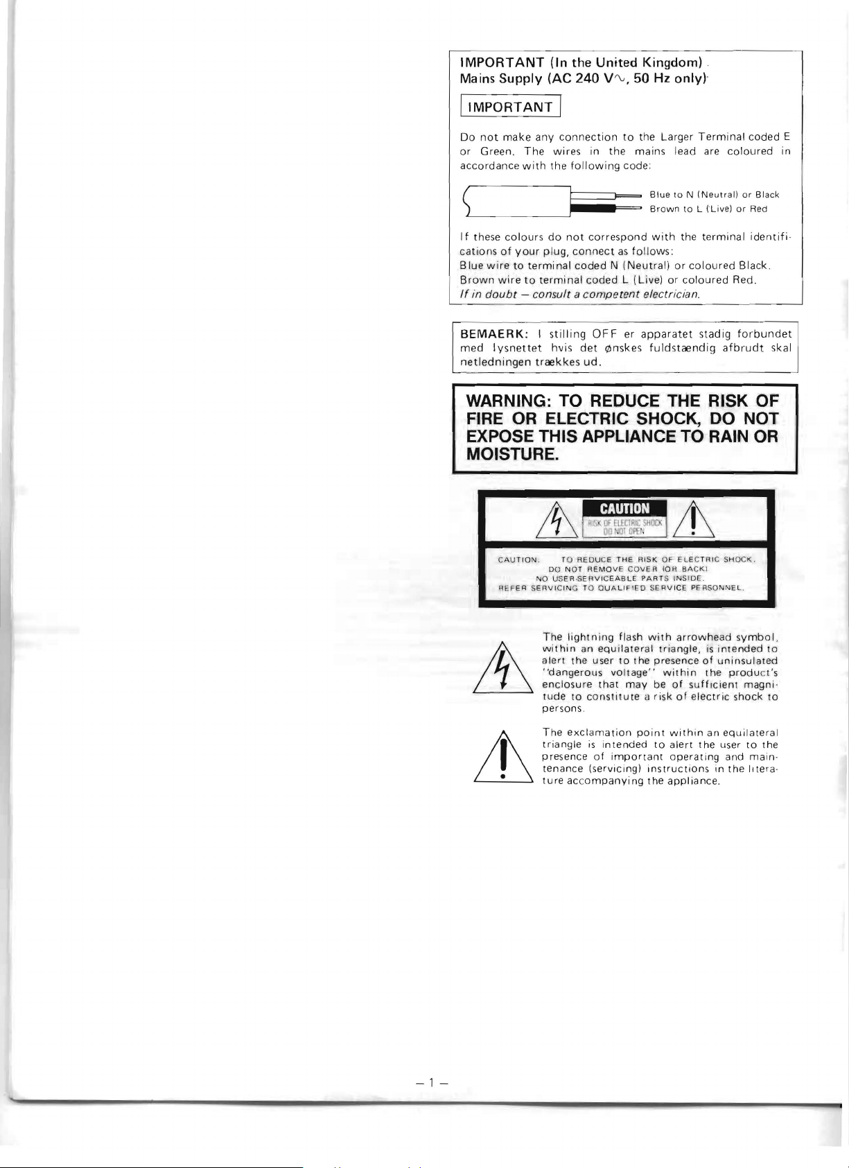
WARNING: TO REDUCE THE RISK OF
OR
FIRE
EXPOSE THIS APPLIANCE TO RAIN
ELECTRIC SHOCK, DO NOT
OR
MOISTURE.
I
LL
TO RE
DUCE
THE
RISK
REF
NO
ER SER
OU NOT R
USER·SERVICEA
V ICING
TO OUALIFIED SERVICE
The
lightning
within
an
alert
the
"dangerous
enclosure
tude
persons .
user
to
constitute
EMOV
E COVER
BLE
flash
equilateral
to
vOltage"
that
may
PART
with
the
il
OF ELECTRI
10H
S INS IDE.
triangle,
presence
within
be
of
risk
C SHO
BAC
K I
PE RSON
arrowhead
is
intended
of
uninsulated
the
sufficient
of
electric
CK
NEL
.
symbol,
produ
magni-
shock
,
ct's
.
skal
to
to
-1-
The
exclamation
triangle
pre
tenance (servicing)
ture
is
sence
intended
of
important
accompanying
point
within
to
alert
operating
instructions
the
appliance.
an
the
in
equilateral
user
to
and
main·
the
litera
the
·
Page 3
IMPORTANT
tCANADA
SEULEMENT)
CAUTION: TO
THIS
(POLA
RECEJ;>TACLE
CAN
BE
ATTENTION:
NE
PAS
PRO'LO'NGATEUR , UNE
AUTRE
PEUVENT
AUCUNE
Note
to
This re
s aller
vid
sp
groun
es
ecif
min
's atte
uidel in
ies
di
ng system
cable ent y as pl-actica l
PREVENT
RIZED)
FULLY
l:JTILISER
SO'RTIE
ETRE
PARTIE A DECO'UVERT
CATV
de r
ntion
PLUG
O'R
OTHER
INSERTED
PO'
U R PREV
CETTE
DE
INSEREES
system
is
provided to call the
to Arti
es
fo r proper grounding and,
the cable grollrld shall
of
t
r"'AJlD" ,
,-",,,,.r
11/1
control
COMPU
di
trolled via
vidual
LINK
is a com
JVC
audio and/or video components
a c
omputer For
ONLY/CANADA
ELECTRIC
WITH
OUTLET
TO'
ENIR
FICHE
PRISE
COURANT,
A FO'ND
installer: (U .S.A. ON L
cle 820-22 of he NEC tha pro-
he uilding,
V
Remote I
AN
UNLESS
PREVENT
LES
CHOCS
PO'LARI
DE
SAUF
be connected
as
,&IV
......
!II
SHO'CK
CO'URANT
DO'
EXTENSION
THE
BLADE
EXPOSURE
ELECTRIQUES
SEE
SI
LES
SANS
EN
NO'T USE
AVEC
O'U
Yl
CATV system in-
Irl
pa icular,
close to th e
,
System
put
er-
link
ed
sys
tem
by
which in-
further
detail
s, see
page
CO'RD,
BLADES
UN
UNE
LAMES
LAISSER
to
the
point
of
al-8
con-
12.
CAUTION-
To reduce the risk
1.
Do
not
remove scre
ot
ex
2. Do n
Th
ank you fo purc
Be
fore Y
ns
tio
pos
OLi
begin operatr
carefully
to be s
ws,
e th
is
applian
has
ing t his JVC pro
Lir
shocks,
covers or cabinet.
ce
ng
this uni
e you g
fire, etc.:
to rain or moi stu
duct
t, plea
se read the instruc-
el
th be
st
possible
of elec
trical
ance.
If
you have a
ny
questions, consul t your JVC dealer.
Note:
This
instruction
the
RX-7VBK
models
scribed,
the
necessary
purchased
is
followed
virtuallry
information
.
booklet
and
RX-9VBK.
identical.
by
has been
respective
relevant
prepared
The
The
model
for
basic
operation
differences
numbers.
to
the
model
CONTENTS
I
mpo
rtant
Connection diagrilm
Antenna
Front
COMPU
Remote
Oper
Ope
Spec
s
pa
nel
LIN
K remote
control unit
atio
n
use.
Before
B
i:ls
ic operation
Pres
etting to selected stati
to
Listening
Listening
Li stenin g
broadca
to
records
to tapes
Watching and listening to V
When the
SOU
Watch i n9 and I istening
Recording t
apes
Usin stereo h
Tape d
ubbin
g.
ra
tion of the
ifi
cations 17
contro
l system
(RM-S9)
ons
(F M
en
AIV1)
sts
ID
EO 1 (V ID
I\!D SELE CTOR function is u
to
a VC R
ead
phones 16
SEA. Gra
phic Eq
ua
EO
sed
li7er
re.
two
are
clearly de-
Please
2)
pert
~r
models
of
both
check
you
have
-
-
2
3
5
7
12
12
14
14
14
15
15
15
15
15
15
15
16
16
IMPORTANT
1.
Installation
eSelect a place which is level, dry, and ne
-2-
cold (between -5°C and
ePay atte
cabinet
lated p
ntion
to
or
using the receiver in a
lac
e may result
trouble.
ea
ve a sufficient
e L
to prevent
2.
Power
e Do
eW
hen unplu gging
not
3.
Malfunctions,
- Do
interference nois
not
handle the
th
~
power cord i tsel
etc.
not
insel-t any metalli c object inside the receiver.
40°
(jQo
d v
in
distance between the receiver and your
pow
er
from
the wall o
f.
ith
er
WU
hot
nor
C/23
° F and
entilation;
104°F)
putting
narrow
thin
gs
on the
arld poorly venti-
the temperature rising and cause
e.
cord
with
wet
utlet,
hands
alwa
l
ys
grip the plug,
too
TV
Page 4
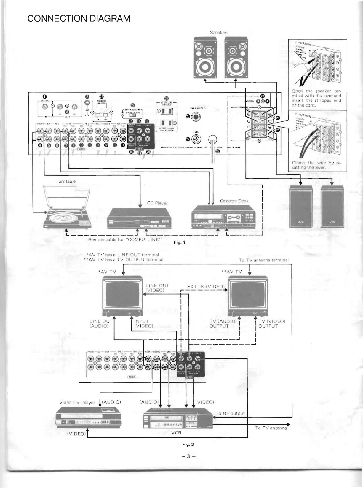
CONNECTION DIAGRAM
r
IfU1lLl-!:Q-'IJI-'''I'f I-I''''ll -'l~lll-VJD{
., ."~i ®
~~~
J
l~';~~J~)
@)@@)
4D4D
T
urntable
2-
@)
@)0@)
4D ® 4D
1t"
@
(®
~
0@)
Speakers
r---
I
I
I
I
1~
1
~~
I
I
I
L
____
Open the speaker termi
nal
with
[I,e
cord.
he
the
the lever a
st
wire
lelier.
insert
of
the
Clamp
setting
,
ripped
by
nd
en j
re
__
-----------------
Q
_
____
Remote
c tIle f
• AV T V
••
r~Hn
i
@0<®
~
has
AV TV has a TV
-
t o -
.iI
\I
( --;}"t
@
~
@)@ ®
CD Player
~
_
a LI
__
or
" COMPU
NE
OUTPUT
,
J L..
OUT
~
__
LI
termina
tew linfll
~
K"
L--------r-----
~
-"
-",
IIo
IfF
@)0@)
=--"=
~'"~wJ~'=-'!:'JK'!V~J
!!!!!!
_
______
Fig. 1
l
J
L
_____
.
=
EXT IN (V
_______
IDEO)
D
. -
rv (A
UDIO)
OUTPUT
I
I I
I
.J
---------......1
I
I
I
I
,
I
J
. ' .
• I
I T V (V I
I
I
DE
OUTPUT
O)
(A UDI
O)
To
TV
V
CR
Fig.2
-3
-
antenna
Page 5
o External
See
o G
o
CA
See
AU
DIO I ... For audio si
I
o
PH
ANTENNA
"ANTENNA
ND
terminal
TV IN
/OU
"ANT EI\!NAS"
ONO terminals
S"
T terminals
o CD terminals
(}
AUX
terminals
o TAPE 1
«i)
TAPE 1
o TAP E 2
4E)TAPE 2
4D
VIDEO
4DVIDEO
ID
VC R REC te
4D
VCR P
Notes:
-These
-The
VIDEO
I
G) MON ITOR O
Co
AV
vided
sicnals.
o MON IT
Conne
wit
termi
m
VID
Connec
a LINE O
mV IDEO 2 term in
II>
VCR REC terminal
WVCR
I GENE
6)
AC
@J
Fuse holder
@)
Voltage
When this equipment is u
volta
selector to t he corre
~
SPEAKERS
~
SPE
~
Power
fD
AM channel
T
se
RE
C terminels
PLAY termin
RE
C terminals
PLAY
term inals
1 terminals
2 terminals
rmin
als
LAY
termina
VIDEO
to
receive audio signals
VCR
for
an
extra tape deck.
I For video signal connection
nnect the
TV
with
with
OR
ct
h a
LINE
nal when the V ID EO 1
EO 1 termina
t any
PLA
RA
LI
OUTL
s lector"U
ge
is
AKERS
cord
he
AM
l c
tion
1 and
terminals can also
UT
A termi n
VID
a T V OUT PUT termin
a video
OUT B terminal
any of
UT
Y te
different from the preset vol t
channel
of 9 kHz or 10 kHz steps, depending on your
severa
OUT ter inal. 0
l
of
several
terminal
al
rmi
nal
ETS (SWITCHED)
H
1 terminals
2 termin Is
spac
ing
terminals
on
page
5.
on
page
5.
gna
l connection
als
ls
VIDEO
EO
MONITOR
input
or
ct
position.
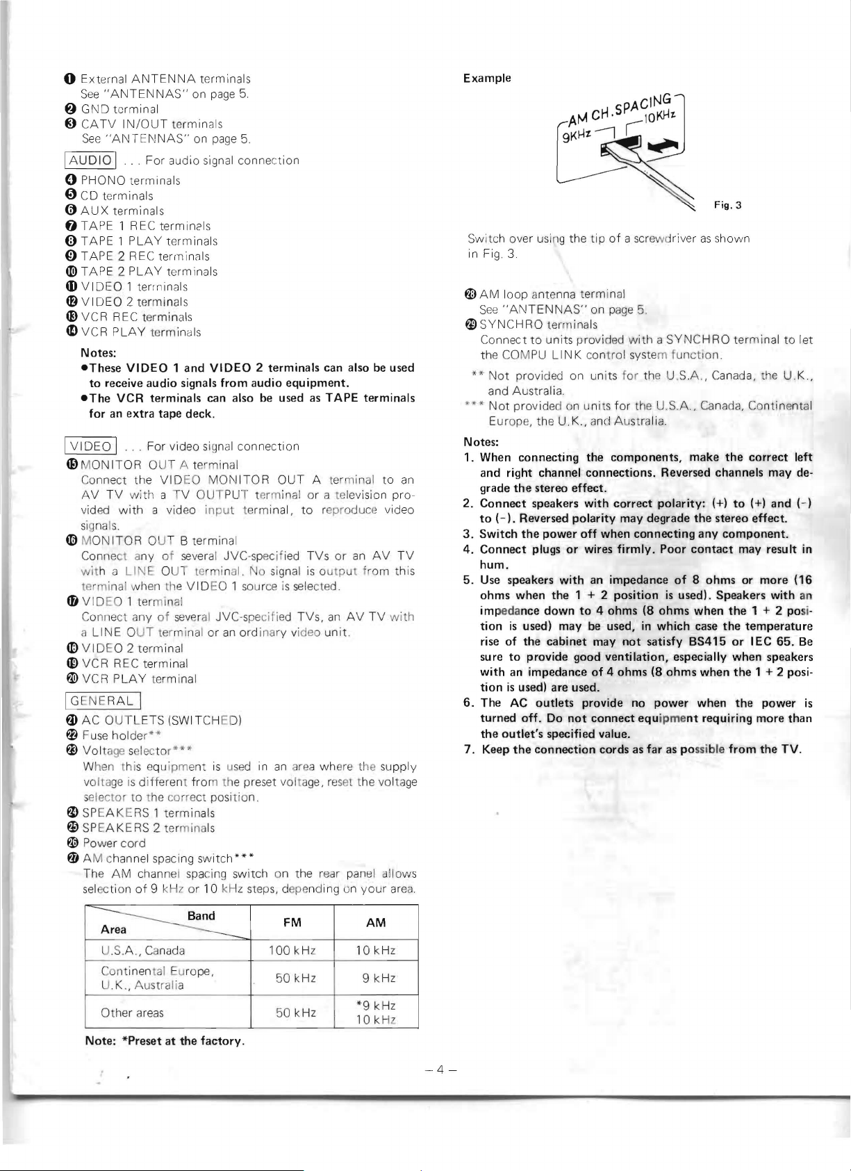
switch***
spa
cing switch on the rear
2 terminals can also
from
audio
equipment.
be
used
al
OUT
termi nal,
l JVC-specif
source
JVC-spe
an
ordinary video un it.
sed
signal
cifi
in
ied
is sele
ed TVs,
an
as
TAPE
terminals
A termin
al
or a television pro-
to
repr oduc e video
TVs
is output from th
cted.
rea
where the supply
age, reset
an
or
AV
pan
al
an
TV
the volta
el
be
AV
used
to
TV
with
allow
area.
an
is
ge
Example
Fig.3
Sw
itch over usin
in Fig 3.
~
AM
loop antenna
See
"AN
f1)
SYNCHRO terminals
Co
nnect to u
the COMPU
**"
Not provided on units for the U.S.A , Canada, the
and Australi
""*
Not
provide
Europe, the
Notes:
1. When connecting the components, make
and
right
grade
the
2. Connect speakers
to
(-).
3.
Switch
4. Connect plugs
hum
.
5.
Use
speakers
ohms when the 1
im
pedance
tion
is
rise
of
sure
to
with
an
tion
is
6.
The AC outlets provide no
turned
the
outlet's
7. Keep
s
the
g the tip
TENN
AS"
nit
LIN
a.
d on uni
U.K
channel connections. Reversed channels may de-
stereo effect.
Reversed
the
power
or
with
down
used) may
the cabinet may
provide good
impedance
used) are used.
off.
Do
specified value.
connection cords
of a sc
rewd river as
term inal
on
page
5.
s provided with a
K co n
trol
system f
ts
for
the U.S.A.,
.,
and Australia.
with
correct
polarity
off
when connecting any
wires
an
impedance
+ 2
position
to
4 ohms (8 ohms when
be
used, in
ventilation,
of
4 ohms (8 ohms when
not
connect equipme
polarity:
may degrade the stereo effect.
firmly.
which
not
satisfy BS415
power
as
far
shown
SYNC
HRO terminal
unc
t ion.
Cana
da, Con
the
correct
(+)
to
(+) and
component.
Poor
contact
of
8 ohms or more (16
is
used) . Speakers
case
especially when speakers
nt
as possible
may result in
the
1 + 2 posi·
the temperature
or
IEC 65.
the
1 + 2 posi·
when the power
requiring more than
from
tinental
with
the
TV.
to
let
U.K.,
left
(-)
an
Be
is
Area
~
U.5
A,
Cont inent
U.K.
Other areas
Note:
*Preset at the
Canada 1
al
, Aus tralia
Europe,
factory
FM
00
k Hz
50
kHz
50
kHz
.
AM
1
0k
9 k Hz
*9
kHz
kH
10
Hz
z
-4-
Page 6
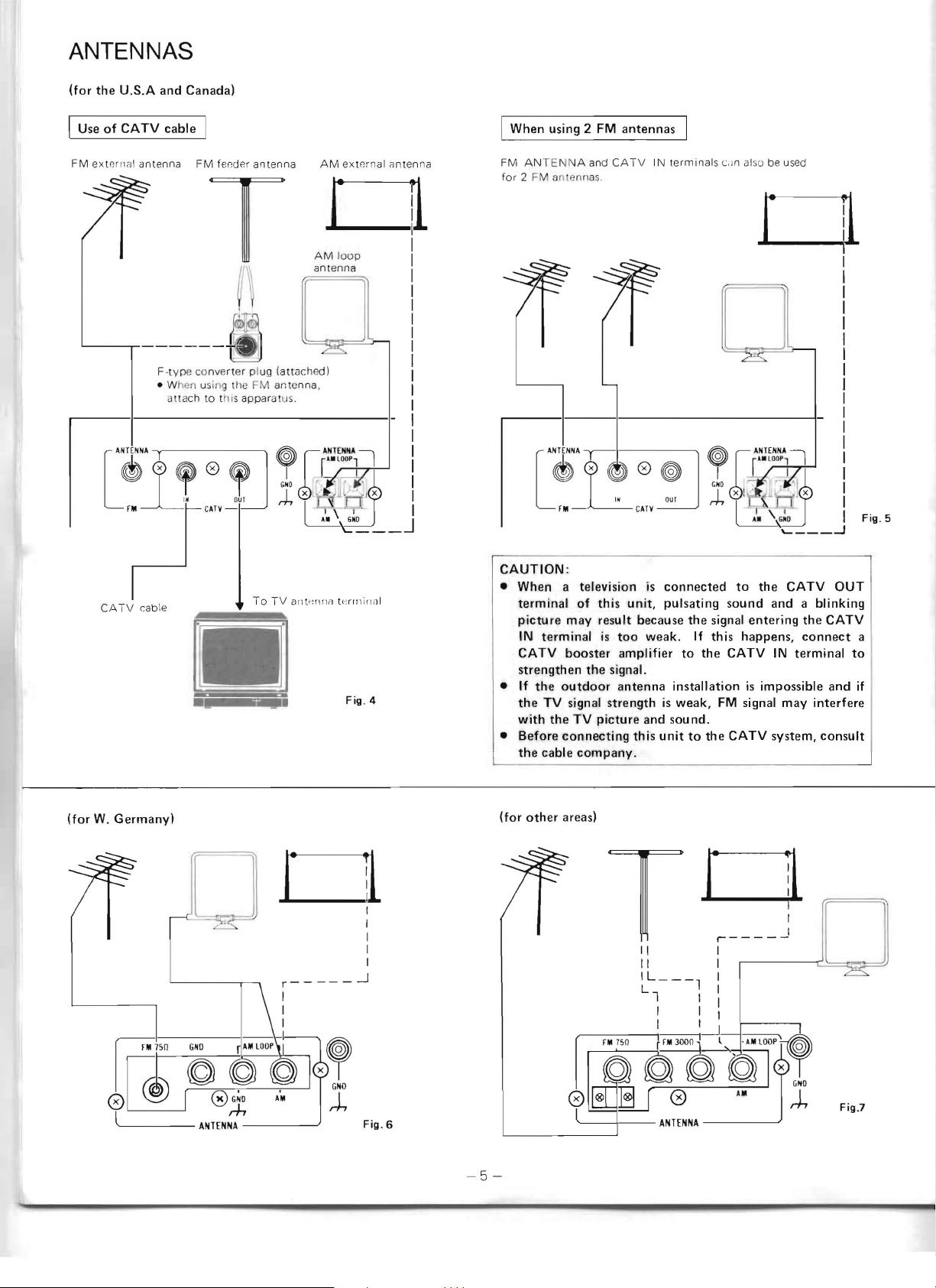
ANTENNAS
(for
the
U.S.A
and
I Use
of
CATV
cable
Canada)
I
I
When
using 2
FM
antennas
FM
exte
'------.-------
CATV
rnal
antenna
cable
FM fee
F-
typ
e co nverter plug (attilchedl
• When using
il1!ac h to this appar
o
der
antenna
T
tile
FM
antenna.
atus.
•
. T
AM
eX18rnal
anten
na
01
AM
loo
p
an tenna
FM ANTE NA and
for
2 FM antennas.
CAUTION
•
When
terminal
picture
IN
CATV
strengthen
• If
the
with
•
Before
the
:
a television lis
of
may
terminal
booster
the
the
outdoor
TV
signal
the
TV
connecting
cable
company.
CATV
this
unit,
result
is
too
amplifier
signal.
antenna
strength
picture
IN
connected
pUlsating
because
weak.
is
and
this
unit
termina
ls
c.Jn also
the
signal
If
this
to
the
installation
weak,
FM
sound.
to
the
be u
01
to
the
sound
and a blinking
entering
happens,
CATV
is
signal
CATV
IN
impossible
system,
sed
CATV
the
connect
terminal
may
OUT
CATV
to
and
interfere
consult
a
if
(for
W.
Germany)
o
x
~
GNO
rh
Fig.6
-5
(for
-
other
areas)
o
II
II
IL_--l
Ll
I
I 1-.-1
rl~~~~~
o ®
~
--
-
ANHNNA
0
I
I
I
I
::
G
NO
AM
rh
Fig.7
Page 7

Fig. S
11iP®
F-type jack (75
Fig.
12
-ohm)
Unit.
Fig.
m m
10
Con
with
Fig.9
nection
this unitl
Fig.13
of
the F-type
and t he
connector
300-
ohm
converter
feeder
antenna
plug
(provided
Fig.
14
AM
antennas
-
How
to
Clssemble
Snap the
until
-Wh
Ch
a best posi
-AM
If
tenna
loop
fi
rmly
en
too
clnge the
externa l antenna (Fig. 4 - 7)
AM
I'ecept
(s
ingle·wire antenn
antenna
held
much no
dir8ction
tion.
ion is n
the
in
ise
Notes:
-If
the
provided
attached,
be impossible
-If
the
AM
or
the
to
loop
loop
antenna
receive
antenna
nals, it may cause noise
rear
panel.
-When
FM
For
-Co
installing an
loop
antenna
antennas
USA &
nnection
Jack
of
the
The F-type
connected
CANADA
of
the F·
75-ohm
input
Jack
AM loo
p antenna (Fig. 8)
onto
the stand, then
rlac
e.
occurs (Fig. 9)
of the lo
ot
antenna
AM
AM
good,
a)
to the
wires
broadcasts.
is
too
and
should
external
op
antonna
connect
AM
ANTEN
is
not
touch
close
be moved
antenna,
the
to
.
(Fig.
4,
5)
typ
e conne
coaxial cable (Fig 10)
is
not
ctor and
provided
with
sli
de
it
as
or
reinstall
an
extern
al
NA
terminal.
set
up
and
rear panel, it will
the
speaker
away
from
leave
the F-type
this
unit
shown
it
in
AM an-
its wires
termi·
the
the
AM
input
- Connect an external antenna
to
I ine
OUT terminal. (Fig 4)
- The f
first and then connect to the F·type connect
pa
- The CATV I N term inal call also
an
2
For
-Th
75
-
75·ohm
is
For
-
75·ohm antenn
t
upper terminal. T
mina l.
- Feeuer
Take care t
any
the CATV IN termi nal, and
eede
r an ten
na
nnel (Fig 11)
tenn
a.
With this arrangement,
FM
antennas for the
W.
Germany
e FM wire antenna
-o
hm coaxial j ck tempora r
to
be
connect
other
Loosen the scre
he
ring f
an
Conne
ct
ot
her terminal.
(Fig.
antenna
ed
wit
to the
areas (Fig.
a with coaxial le
ws
rom
below. Then connect the
he
tenna (Fig 14)
to
the
300-ohm
ha
t the wires
must
6,
h coaxial t
7)
on the bracket and insert t
brac
to
bes
t recep
the FM
be
attach ed to t
tion.
(I
television
be
used for
you
can
(Fig.
terminall , th
12)
pro
vided can be connected
ily.
ype
conne
75-ohm
terminal.
of
term inal.
ad
(Fig 13)
suipped
ket
ring
works
the feeuer antenna
e
to the CATV
he
conv
ert
er
or
on t
an
ex tra FM
s\ivitch between
5)
ctor
(DIN
45 332)
he cable i
core
as
the ground ter-
do'
not
Cli,
TV
pi
ug
he rear
to
the
nto
to
th
touch
e
-6-
Page 8

FRONT PANEL
:~::
:
~-
"""
.
..,
.
J,
- - I:::::
..- -
.::J
::::::
I:::::
:::
::
:
m::
I:::::
:
o
PO
WER
ON:
Pre
ss
to
!U
rn
the power on . To turn the pow
press
it
ayain.
STAND
tt1e
source s
alteration as Ion as the power cord is
outlet. This situation
The p
ed even in t
c
or
does
Note:
- Even in the
f)
SPECTRO
GRAPHIC
This displ y d
and
switch
SPECTRO
divided into se
cies are identical to those of the sev
SP CTRO
le
dic
rising and slow
BY: E
ven
when all of the indicators are tu rned
memo
ry
circuit operates
electorsare not subject to cancella tion or accident
re
set
(l
a and t
he case
d is disconnected,
not
exceed a couple
small
amount
completely
an
vel in each frequency
a1:or
off,
PEAK
EQUALIZER
SEA
ed between displa
PEAK
PE
is d
esi
of
STAND
of
electricity
disconnect the power cord ,
INDICATOR/SEA
ou
bles
GRA
PHIC EQ
INDICATOR:
ven frequency bands, who
AK
IN DICATOR show
gned so
er
\iv
hen dec
and the preset stations and
is
called t
he SOUrce select dat are main ain
a power f il ure or when
if
the period power
of days.
BY
mode, this receiver consumes a
(5 watts).
indicator
as
a SPECTRO PEA K INDICA
UALIZER
ys
by pressing the SPI/
ban
d.
lha
t i
ts respon
ilying.
plu
ged
he
STAND BY mode
is
To
shut the power
indicator, and is
SEA
The output signal
se
center frequ
en SEA bands. Thi s
s the ou
Fur
eas
ier viewiny, Ihe in-
se
time is faster wh
er off ,
off
mto
an
the p
ow
not
applied
TOR
butto
tput signal
th
al
AC
n.
en-
en
Fig.
15
GRAPHIC
SEA
falls in response
LEV L u tto
,
e
.
-
r
is
band.
Notes:
-The
SEA
for
about
applied.
-When
~
SEA PRESET
Pressing
indicator
patte
par
p t ern
These indic
h
newly·
o
MANUAL/PROGRAMED
Pressi
"MAN
indic a ing whic h mode has
o
MEMORY
Pr
five
memory the pat
the SEA
REVERSE,
button
INDICATOR
as been pr
is
the MA
A,
rn
was
ticular mode (MA NUAL or PROGRAME
was
created patt
ng the
UA L" or " PROGRJ\M ED"
essi
ng the ME !lO RY b
seconds, th
EQUA LIZER: The dot point
to
the pres in
ns
to show t
GRAPHIC
five seconds immediately after the power
MANUAL/PROGRAMED
pressed, the display shows the SPECTRO
B,
eing used t
being used, no
ato rs also light when
essed,
indicator
EQUALIZER
LEVEL,
after five
indicator
C,
MANUAL/PROGRAME D
us
te
sec.
NUA
L/PROGRA MED butto
D, or E 0
to select a p
ern in memory.
indicating the unit
rn
you have created.
of
the corresponulng SE.A
he
SEA level in
level indicator
SEA PRESET, SEA
or SEA
light, ac
he
last time t
res
indicator
been sele
tto
cording
he unit was
et
patte
rn
indicat
an SEA PRESET bu
reset
pattern or to store a
to light on the display,
cted.
n ligh
ts"
EMOR
is ready to s
rises
each
frequency
is
FLAT,
MEMORY
n will cause
to
which preset
D)
If
no
or will light
ut
ron ca
Y"
for abo
and
shown
SEA
PEAK
in that
prese
tto
use
tor
e in
is
t
n
s
-7-
Page 9

o
SOUND
This shows
sou rce selectors,
f)
SOU
This
has
(j)
MM/MC
"MM"
in
(c
o TAPE 2 MON
This
4D
COMPUTE R SEA indicator
When
lights
to
When the SEA R
bing,
cessing the signals
REC terminals.
When the SEA REC
lights
output
4D
ACOUSTIC
This
button
4P)
VISUAL
This shows which video signal
VIDEO
fD
VOLUME/BALANCE/SPI
TIMER
This
DISPLAY
"VOLUME" lig
sound going
BALANCE
bar,
and
When the
indicator
DICATOR".
trol
Each
setting
minutes,
each
point
useful
continues
SLEEP
returns
4D
MUTE
This
pressed. Pressing
level. Pressing the
the mu
G)
AMP indicator
The
~
TAPE
When the TAPE 2
dicator
4D
REC
The
the TAPE REC
indicator
which
audio signal
for
listen i
NO
SELECTOR
indicator
been
pressed
indicator
or
" M
C"
use.
This
<Jrtridge select) but
indicator
the
SEA SOURCE
to
show
the speakers or headphones.
the
right
to
show
from
the REC
indicator
lights when the
to
ON.
(RX-9VBK
is shown
indicator
ton
ITOR
indicator
liqhts when the
that
the S.E.A.
EC
button
arrow
lights
output
button
that
the
OUT
EXPANDER
indicator
has
lights when the
been
pressed
indicator
source selectors,
(x
10
MIN)
indicator
indicator
"L",
left spea
unit
time
is
10-minute
does
to
TIMER
to
is
uS8d
LEV
EL , and SLEEP
hts and this indicator shows the level
to
the speakers or headphones. When the
buttons
and
kers
DISPLAY LEVEL buttons
shows the level
is
pressed,
the
increased
with
not
check the
in
the
<Jre
"R"
I ight and
is
shown.
When the SLEEP
"SLEEP
SLEEP
in
a square on
increment added. However, the
light
in
timer's
the
BALANCE,
indication
VOLUME
indicator
indicator
ti
ng.
arrow
lights when the
it
again returns the voluem to its original
VOLUME
shows which source
2 DUB indicator
DUBBING
lights.
OUT
indicator
arrow
shows which audio source
or
VCR REC terminals.
has
been selected
ng
to
or
r'ecordi
SOUND
only)
to
indicate the
can
be
switched
TAPE 2 button
button
is
pressed, the upper
is
processing the signals fed
is
pressed during
to
show
from
the
is
pressed, the lower
SEA.
is
terminals.
indicator
ACOUSTIC
to
ON
has
been
for
watching
DISPLAY
as
the
VOLUME,
TIMER
rressed,
button
10-minute
this mode. This
indication
"BALANCE",
the
balance betwe€n the
of
the "SPECTRO
button
TIMER
is
pressed, the sleep
increments
this
turn-off
SPI
for
about
mode.
MUTE
UP/DOWN
is
output
button
with
ng.
SELECTOR
type
by
that
the
TAPE 1 REC
processing
selected
or recording.
button
of
cartridge
the
MM/MC
is
pressed
arrow
TAPE 2 dub-
S.E.A.
is
pro-
or
VCR
arrow
the
signals
EXPANDER
with
LEVEL/SLEEP
BALANCE,
indicator
on the remote con-
(x
indicator
timer.
DISPLAY
five seconds and then
buttons
to
is
is
being
Normally,
the
center
are
pressed,
PEAK
10
MIN)"
indicator
buttnn
the
pressed, this in-
lights.
timer's
to
up
to
lighting
leftmost
is
The display
LEVEL,
has
also cancels
amplifier
output
right
this
also
been
from
the
the
SPI
of
IN-
60
for
or
4D
VIDEO
The
REC terminal
CD
LOUDNESS indicator
When
tor
W
FM/AM
"FM"
AM
6)
Frequency indicator
The tuned-in frequency
(kHz)
(for
tries)
played
~
SIGNAL
This
signal strength
OUT
indicator
arrow
shows
which
video sou r
or
the
MONITOR
the
LOUDf\IESS
lights.
button
has
indicator
is
displayed during FM reception and
reception.
is
displayed digi
are displayed during
Continental Europe,
or
four
digi
ts
during
FM reception
is
LEVEL
used
indicator
in
tuning
is
shown at three levels.
(MHz)
to
both FM and
AM rece
U.
K., Austral ia, and
(for
Note:
-The
signal
strength
each
band
is
shown below.
LOW
FM 10 -
AM
@)SIGNAL
LEVEL
This
the
the presot station, and the stop level
tuning.
Th
is
STRENGTH
pressing the
shown
40 -
STRENGTH/TUNER
indicator
indicator
tuner
preset indicator showing the channel
indicator
and the
CH/dB
by
pressing 1!he
35
dB
65
dB
is used
can
in
dB
corresponding to
40
- 55 dB
70
-
as
the
cJB
be
switched between
TUNER
button.
STOP
The STOP
LEVEL
Notes:
-0
dB
corresponds
to
11lV/75
inAM.
-The
indication
-The
optimum
mono, more than
If
the
signal
is
shown
signal
60
is
too weak
in 5 dB
strength
dB
for
or
FM
too strong, this display may
not indicate the correct value.
-
Even
if the
dB
display mode
button, the CH indication
when the station
TUNING
button
select
is
pressed,
is
is
buttons
the 0
ed.
-If
a broadcast
CH/dB button
is
received
is
pressed
by preset
so
that the
played before switching the power
will
be
displayed when the power
~
FM
MODE/FM
These indicators show
according
MUTE
to
the setting
indicators
"AUTO"/"ON"
of
the
FM
ce
is
output
OUT
terminals.
been
pressed, this indica-
pt
ion,
U.S.A. and Canada)
AM
MID
85
dB
"AM"
tally
five digi
broadcast
each
More than
More than
to the VCR
during
Four
digits
ts
(M Hz)
other
coun-
are dis-
s.
The
level
HIGH
60
dB
90
dB
in
PRESET/STOP
signal strenqth
indicator
PRESET display modes by
LEV
button.
ohms
in
the
E L display
FM
and
indicator,
number
for
auto
S I G
NA
11lV/m
of
steps.
is
more than
stereo,
set
by
displayed
are
dB
off,
is
switched
MODE/MUTE
40
dB
and
70
dB
for AM.
pressing
pressed.
indication
tu
ning,
dB
the CH/dB
and
maintained
When
is
and
then the
indication
display-
the CH indication
on
again.
or
"MONO"/"OFF"
button.
for FM
the
is
dis-
L
is
-8-
Page 10

Gl
STEREO/OSC
STEREO: When
this
indicator
"MONO",
broadcast
MODE/MUTE
OSC: When the
is
lOIN,
ntrol)
Co
~
AUTO
MEMORY
Lights when th e A
~
MEMORY
Lights for about fi
ressed
p
in me
mory
@
CATV
indicator
When the
to
lights
~
PRESET
Each
time
dicator
preset stations
~
REMOTE
Wh
ile
infrared signa
control
~
MEMORY
Pre
ss
this
show th
the station
lit
(for
station in the specified
number
~
AUTO
A fter sett in g the s
pr
ess this
STA
TIONS
matically Sl a
tu
ner tunes in
broad cast is tuned in. Then its s
dB
for
ed
earlier fl ickers
store this station
seconds; the dB indication is s
starts again. Oth erwise, the MEM
n
el
number I ight together and the frequency
th
at channel . Then the
and up·s
for
a frequency
continues
station has a frequency stored
If
the upper
thi
s happen
display
ed
Otherwise, w hen
indicator
an
FM stereo broadcclst
lights. When the MODE indicator
this
indicator
is
being
button
siDnal
this indicatur ligh
circuit
is switched on t o reduce noise.
rec
eiv
so
strength
will
ed.
that
ts
not
In that
"AUTO"
of
and th e
indicator
UTO MEMO
RY
indicator
ve
seconds when the MEMO RY
to
on, or
for
during auto
(only
CATV
button
show that this
SELECT
indicator
the PRES
shows "1 -
to
be
one second
memory
for
unit
ET
SELECT button
8"
or
selec ted.
"",,he
the U.S.A. and Canada)
is pressed to
receives
"9
- 16 "
SENSOR
ls are
being received from the remote
unit, the RECEIVED
button,
ul
it is rea
and the
dy
select bUttOll
about
five seconds) makes
indica
MEMORY
to rece
ive a mem
while the M EM
memory
is
shuwn
in
the display
MEMORY
top
level using the STOP LEVEL buLl
button and
butt
rt
ing
to
ons
then one
to
scan
arld preset broadcasts
frum
the frequency b illg displayed, the
incr
eas
ingly higher frequencie
ig
one second and the channel
for three
in
memory,
seconds.
press
ho
wn and the
next channel
ca
nning
res
tart
s,
as
the
tuner
to
store
in
the next channel . This process
until
the highest numbered channel pl'eset
in
its
limit
of
the frequency band
s,
the upper
instead of the channel
thi
limit frequen
numb
s process ends, the last frequency tun
is being received,
lig
ht
even
if a stereo FM
case,
press
the FM
is
shuwn.
an
FM stereo broadcast
QSC
(Quieting Slope
button
is
set to on.
button
n a frequency is stored
on,
th
is
indicator
CATV
prCllJra
ms.
to
tor
lights.
indicator
is pressed
sh
Oll"
, this in·
th8 (]roup
wil
l light
ory setting. Pressing
ORY
indicator is
it
possible
At
this time, the channel
of
the T
to
store thr
UNER PRESET
s, unt
nal strength
number
I f you don
is shown in
you
ave
't wish
this button within four
sca
n func
ORY
indi
cator
and chan·
is
stored in
numb er
autorT
1Cllica
is
ily
searches
memory.
is
reached
cy
is shown with dB
er
to and its corresponding channel number are displayed.
If
, whi
le
this operation
broadcast band,
pre
ssed, the
being
operation stops and the broadcast cu rrently
tun
ed
to
is
th
at
heard.
is
taking place w
same
broad
If a different
ithin
a pa
cas
t band b
utt
broadcast band button is pressed, the operation stops and the broadcast last
tuned
to
when
that
bund
was
listened
to
is h
eClrd.
shows
on,
auto·
il a
press
tion
shown
before
rti
cular
on is
is
of
to
to
ed
Note:
To
cancel the auto
tons in the
or
PRESET
@)
PRESET
Press
to
tuner
SELECT
SE
LECT
set
9 - 16 PRESET
for
each bClnd
Even when
1 acc
om plish preset
SE
T S
~
CATV
To l
ttached
a
gram recei
b
utto
When
you
8 and 9 - J6 by pressing this b
TATIONS button
(only
isten to an FM broadcast re eived by .he FM antenna
\0
ved via the connected
n The
th
e
CATV
by th e an enn a connected
can
be
heard. In addition,
be stored in p
portio
n of
(j
pr
'opriate PRESET STATION
is
then
not necessa
ij)
TUNER
Th
or to sto
ose
PRESET
butt
ons
re a fr
When one of th se bu
shown by the
If
one
of
these b
bul
ton
has been pr
ceiv
ed
will
be
~
STOP
LEVEL
This
is
used
to
the
scan
tunin
Clnd
60 -90
memory
section
function,
other
press
than the
one
AUTO
of
the
but·
MEMORY
button.
to preset channel s 1 - 8 or 9 - 16, 1 - 8 or
SELECT
(FM 16,
pushed ME
AM
memory
indi
cator
lights. Up to 16 stations
16)
can
be
MORY butto
utt
by pressing the
preset
as
required
n and th en changed
on,
it
is
possible
TUNER
PRE-
.
for
the U.S.A. and Canada)
the
CAT
CATV
indicalO
V IN terminal ,
indic
ator wililig
r is not l
CATV
it,
or
to
a cable TV pro-
cable, pr ss this
t.
FM bro
ad
cas s ceiv
ed
lO the FM A NTENNA terminal
CAT
rese
t sta
lion memories.
CATV channel
V chann
so stor
butl
el
frequencies c n
To hem the audio
ed, si mply press
on.
Pressing
his
the ap·
button
ry.
STATIONS
iJ
IC
used
to select onc
equency in mem
tlo
ns
TUN
ER PRESET indicat
utt
ons is pres
essed, the
sto
red
in me
mor
set
the strength
g sto
ps
by 5 dB steps
clB
in AM.
is p
y
of
the
pn
ory
.
res
sed
, t
he
preset number is
r.
sed
when the MEM
frequency which
of
broadcast signa
for
30 -60
~set
sta tio
is
being
ls
at
dB in FM
ORY
reo
which
to
ns
Note:
-0
dB
corresponds
in
·
AM.
~CWdB
Pres
s to
sele
ct e
ti o
n.
If
one
of
the s
hand, o
no effec
@l)
PRESET SCAN
This bu
this b
number flas
each
bCln
nly
the dB indi
t.
tto
n per
utton
is
he
of
the other
d) have been scanned. When the de
received, pressing the PRESET SCAN
sc
anning and the R
stalion, If no stations were selected
th
e frequency tuned to befure
is
tuned
to Clgain.
to
1/_N/75
ith
er the channel indication
tation select bu
ca
tion
mit
s
sCannin~1
ohms in FM and 1
tto
ns
is
not
pre
is
shown and this b
of the prese
t statiuns.
or
sse
pressed, preset station 1 is tlJlled in,
s for
about
sta
tions,
five second
unt
s.
Thi s continllr:s for
il 'all 16 (in th e
AM
sir'ed SlJlio ll
butt
on stous the
X-7VBK/RX-9V8K
remains tun
durin~l
this functi
on
this fu
was
flV/m
dB Indica·
d
bef
()'-I~
utton has
I/I
'ilcl
anLi
its
or FM
ed
to
the
nction,
in iti,lt(~d
'
l
is
-9-
Page 11

~
FM
MODE/MUTE
For normal FM rece
interstat
"AU TO"
ion noise, pre
and FM MUTE's
ption
ss
this
"ON"
and
button
au
toln 8tic
so that FM
li ~Jht
in the display
When recei ving a weak or noisy FM stereo broadca
this b
utt
on
so
that
F MU
TE lig
ht; the broadcast
the clarity of reception
(ID
TUNING
DOWN:
UP: Press to
Manual
Tappi
te
s
Auto
Holdin
a
nd then e
re
ceived, tuning
in, scann ing
In
Note
-When
causes
UP!DOWN
Press
to
tune
tuning
ng these bUllons
ps
of 9 or
10 kHz in
tuning
g either button pressed for mor than o
leasing it start s auto luning; when a
cont
aut
o luning, pressing
:
one
of
these
to
change at the
quency band. I n
verses
direction
<D
SPEAKERS
"MONO"
tune
to
to
higher frequencies.
wdl
sto
inu
es even
buttons
auto
when the
of
FM
MOD
E and "OFF "
will
be
hea
rd in m
will
be
improved.
lower
frequencie
s.
changes the frequency
AM,
or 50 or 100 kHz in Fivi.
p.
But
it
eit
her b
utt
either
upper
tuning,
upper
when a
button
is
bro
adcast IS received.
agai
n stops scanning.
being tapped,
or
lower
limit
the
frequency
or
lower
limit
SPEAKERS-1
P:
cso;
to
switch
the
spea
te
rmina
ls
on
or
kers connec t
off.
ed
to the
SPEAKERS-2
Press
to
SWitch
the
speak
ers
termi nals on
(D
Headphone
or off
jack
(PHONES)
Plug stereo headphones
an
d recording monitor
fro
m t
he headpho
to
OFF
.
(DSEA
(D
PRESET
Press
to
store the displayed
recall t
he
preset S.E.A. pa
pre
ssed Whd
M
EMORY
stor
the patt
mo
de, th
priate
SEA PRESE
can
be
stored f
A d
iffe
rent set
th
e PRO
CLEAR,
n
ently stored in memory
may n
ot
F
or
more
SEA
LEVEL
The bui
into
ll-i
seven
in
butt
on and then one
ern you have created. La
at
patte
or reca
GRAME
SOFT, MOVIE, and VOCA
be repl
ace
deta il
s,
n graphic equa li7er
frequency bands wit h center frequencies
63 Hz to 16 kHz
When the
quency
be varied
S.
respo
by
F A
nse
±10
connected
.
into
this
ing.
If
you want
nes
onl
y, pre
S.E
ttern
corresponding
the M
ANU
AL
rn can be recalled by p
T b non. Up
ll in this way.
of
S.E
.A patte
D mode. Th
ese five
before
d So,
up
to
refer
to page
at intervals
level is
is
flat. T
dB
by
16.
of
4/3 octave.
set
to
he
pressing
to
rhe SPEAKERS 2
Jack
for
private listening
to
ss the SPE
.A patt
mode,
of thes
AKERS buttons
ern
in mem
preSSing
e five uuttO
ter'
, wh ile in MA NU
res
to
five original patterns
rns
is ava
pat
terns (HEAVY,
L) have bee
the
unit
\N
10 pat terns may
divid
es
the
audio
'0' (cen
ter iJositionl. fre -
response in
the
UP
LEV EL buttons.
elimination
MODE'
st, pre
ono
but
in
single
ne second
bro
adcast
on
is
kept held
the
frequency
of
the
fre-
scanning re-
is
reached.
SPE
A K F
F1S
listen to sound
ory
or to
to the b
the
utton
SEA
I1S
will
AL
sing the appro-
ilable '.'·J
hen in
n perma-
8S s
hipp
ed, and
\)('
recalled.
spec
trum
from
each band
or
DOW]\] SEA
can
of
ss
of
The bu
ttons for diff
at
the same time, and holding
to
s
continue
63
Hz: Raise to
rising
or08ns, drums, and
sound With emph
r
es
ponse
of
low
160
Hz: Empha size
De-emphasi
or
nearly empty
400
is
constructed. Emphasize
Hz:
Le
Thi
s frequency range
erent
fre
quency b8nds C
them down
or
falling.
emphasiLe the very l
cont
rabass.
asis
and eli
minates t
frequencies
to
el
i
with de-emph
to
obtain a more
rn
i nate u ncle8r
listeninq rooms.
to
really
8n
be
pre
sse
causes
the
level
ow
bass
respo
nse
of
It produces stable and solid
he
unclear sound
asis
expanded
sou
is
the
b8se
put a punch in
nd caused
low
sound.
by
laroe
on which music
your
d
music.
in
1 kHz: Most eff8ctive
hlllilan voice. Em!)hasize to
to
the foreu,round, or de-ell1iJhasi/e
into
is
the bac kwound.
2.5
kHz:
This fre quency stimulates the human
music sounds hard
kHz:
Boost
6.3
to
quency band vari
s
ubtl
eties
of
16
kHz:
the delic
ing in a more
of
extension.
pensate f
cartrid
1
(9
fr
oln
SEA
MEMORY
Press
the mus i
Boosting this frequen
acy
of t1igh
ea
r-pleasing manner, and provid
This fr
or
cartr
ge
s h
ave
the
10k
Hz
to
20 kHz.
this bu
tto
n and the M
for abou t five seco
PRESET
currently
(Ii)
MANUAL/PROGRAMED
Press
SEA
(II
SOUND
When th
TOR indi c
a di
signal orig
buttons
be
in
g displayed.
to
switch between the
pattern mod
SELECTOR
is but10n is
alor), the SOUND
ffe
rent
AUD
IO source in c
inatin9 from
es.
Example: When the
SELECTOR
Now, press
AM,
FM, TAPE 1, TAPE
the VIDEO 1 te
OU
T A terminal and t he V
button
n A U
rmin
SOUND signal from the a
sp
eake
rs
or headphones, and
R
EC termi nal. In th
and V
ISUAL
signals
(ID
SEA
FLAT: Press
REVERSE:
ch
ara
cter ist i
SOURCE: Pre
sated
sou
nel
this bJtt
Press
cs.
ss this
.
emphasi7ing or de·
caUSE:
:ile vocalist
or
metallic, de-emphasiz e.
add
clarity
to
winds and strings This fre-
es
the tonal expression , influencing the
c.
cy
ran
s,
with
cymba
ls a
equency band can al
idge response sin
ir
res
onance pea
ce
ks
EMORY
nds. Whi
to store
Ie
it
is
I it, press one of the SEA
in memo
MANUA
iJress
ed (lighti
ng
sig
nal can be sele
ombinat
the V IDEO source.
VIDEO 1 button
are
pressed:
DIO
source selector
2,
al
AUX)
is outp
ut
IDEO
udio
The V ISU
to
VCR R
source
is outp
is
way, a VCR
from serarate sour
on for a
this butt
button
flat respon
on to reve
to listen
emphasi/ing
to
to cause it
ge properly adds
nd
triangles resound-
es
so
be used
most movi
in
the
frequency ra
ind
icato r will light
ry the
L and
SEA patt
PROGRAMED
the SOUND
ion
with
the V ISUA L
and
the
button
(CD, PHONO,
AL signal
the V
IDE
O M
EC
terminal The
is
heard
ut
to
the
AUDIO VCR
may
record the SOU 0
ces.
se.
rse the
to
the S.E.A. compen-
be
brought
to rece
ear. If
a feelin
to com-
ng-
mag
SELEC-
c
eel
SOUND
ONITOR
from the
pattern'
the
de
the
to
net
nge
ern
fr
om
from
g
s
10-
-
Page 12

REC:
Press
this bu
signals.
Notes:
-The
settings
in
the
-When
is
pressed,
mode
<ID
VIDEO
VIDEO
unit
video
VIDEO
vid
eo
unit conn ected
VCR:
Press
connected
~AUDIO
AUX:
to
the
AUX
CD:
Press
connected
PHONO:
PHONO terminal
IFM:
Press
AM:
Press
TAPE
TAPE 1 ter
TAPE
TAPE
2 terminals.
this
func
button
select
~
SPI/SEA
Press to
PEAK
level indica
~
DISPLAY
Adjusts the relative display
PEAK INDICA
signals c
button
~
MC/MM
Press
MM:
play when using
an
output
MC:
Press
when using
0.5mV.
~
LOUDNESS
Press
this
tivit
y at low li stening lev
~
ACOUSTIC
When this
ca
tor
indi
si
aural
sounds be
of the SOU RCE and REC buttons
signal
flow chart.
the
TAPE
1,
TAPE
either the SEA SOURCE or the SEA REC
can
be
selected.
1:
Pre
ss this
connected
2:
Press
this
this button
to
the VCR terminals.
Press
this
button
terminals.
th
is
but
ton
to the
CD terminals.
Press
to
listen
s.
th
is
button
th
is
button
1:
Press
to
listen
minals.
2:
Press
to
listen
Another
tion
so
that
may be heard.
sWitch the
INDI
CATOR
to
r.
LEVEL
an
has
no
(RX-9VBK
of
this
button
(DOWN/UP)
TOR
so
be
displayed in
effect
on the
only)
this
button
an
MM
more than 0.5 mV.
butt
oll
an
MC cartridge
to
EXPANDER
button
light
gnal
tte
is
s and the sound image is expanded; a mon-
will
be
given a stereo
r.
Notes:
-When a TV
tor (mono -
or
VCR
Land
terminals.
-The
ACOUSTIC
EXPANDER
corded.
tt on
to rec
ord
2,
or
TAPE
button
to
button
to
to
to
the source selected
so
compensate
presse
is
to
select the source
the
VIDEO 1 terminals.
to
select the source from the
the V
IDEO
2 terminals.
to
select the source
to
I isten
to
the source connected
to
I isten
to
a compact disc player
to a turn
I isten
I isten to
to
to
press of
indication
and SEA
that
output
so
that "MM"
cartridge
that
els.
d, the
monaural,
R)
for connecting the left
table connect
to
an
F M
an
AM
a t
ape
deck co nnected
a tape deck connec
this
between the SPECT RO
GRAPHIC
position
eS[.Jecially
an
easy-to-see
sound lev
or
an
"MC"
is
shown on the
with
an
for
the ear's l
ACOUST
effe
ct and a stereo signal
use
the
sound
S.E.A-cornpen
2 DUBBI
from
broadcast
broad
cas
button
by
anoth
EQUALI
on the SPECTRO
weak
or
position
el_
is
shown on the dis-
Me
cartridge
output
IC EXPAI\JDER
Land
effect cannot
sated
are
shown
NG
button
fro
m the
the VCR
ed
to
t.
to
ted
to the
will
rele
er source
ZE R
strong level
This
with
ciis
play
of less
ower
than
sensi-
R distribu-
and
right
be
the
the
ase
re-
~TAPE
Press
to
An
oth
er press
~
BALANCE
Use
to adjust the balance between th e
ers.
Pres
the
left
right. H
ously. The
~MUTE
Press
this button, and the
s
ound
to
its original l
BA LANCE
~
VOLUME
Adju
st the v
button
DOWN
shown
these
buttons
or fall.
2
DUBBING
dub
from
of
(LEFT/RIGHT)
s the LE
by
one step and the
olding
them pressed changes the balan
BALANCE
will
be
instantaneously muted.
eve
or
VOLU
(DOWN/UP)
olume
once
to
button
once
by
the
VOLUME
will cause
TAPE 2
this
FT
increase the volume
to
TAPE
1 and VCR .
button will rele
butt
on once
indic
ator
MUTE
l, press this
ME
bu ttons.
of speilkers or headphones
to
dec
rease
indicator.
the
RIGHT
is show
indicator
button
it
volume
to
adjust the balanc e
button
To
by
by
one step; this lev
Holding
ase
this funct ion.
left
and
riyht
speak-
to
adj ust
ce
cont
n on the display.
will
light
and the
return the volume
again,
or
press
Press the
one step, and the
down
one
to
progressively rise
to
the
inu-
the
UP
el
to
is
of
-
11
-
Page 13

COMPU LINK REMOTE CONTROL SYSTEM
,.",aJlDII
...
",,,,r
III/
Remote
Control
The COM
JV
nent
following
Au
If the attached r
other
be s
butto
aL
llOma icall y. TIl e
unit
so
c.l
When
as
component will
Synchronized
$yncll ronized record
cassette cleek
chronization
Set the
procedures in the
VI
hen sy nchronoLJsly recording the CD plrlyer , push the
PLAY button
PU
LI N K remote COl11rol system was developed by
c. YOLI
tomatic
the cassene deck ,
can
from
the
advanced
source selection
JVC
com
witched wil
ns
and the corres
or the a
be
used
.
switch
ing over
with
cassette
not
remo
emote
ponen
h J
ust
ppropriate
stop /lldym
recording
dutomatlca
Ihe
deck
instructio
on the CD player
only
conlrol
te control 'u
operatio
cab
ts
wit
h SYN
one touch 0
ponding com
SourcE!
select
component's a
from
turntable
g
il19
refers
lly
CD
playel or turn
to
R EC/P
n ma nual,
1
I&lV
v
...
/111
Component
path
nit
ns with
le
one
dfter
ease
is used
CHRO
thi
pon
button
component
or
CD pli:lYer,
abuut
to
the process whereb y the
(;Qml
ences ecordlng, in syn-
tI-.
USE
w"
COMPU LI N K c
, bu t also p
.
to
conne
term inals , sources can
s un
ent
of
ctiv
five seconds.
tahle
l11
0de
erfo
rm the
ct
thi
s uni t
it's sou
re selertor
will sti:l
the
ation
. .
rt
remote
button rna
to
another
the
accord ing
PI
omp
to
cont
, such
ev
to
to
plCl
rol
iuus
the
Th e cassett
CD pla
SvnchronizeeJ recording s
player stops playing.
To
canc
o-
Y
y
the CD player, tura
Notes:
-When
after
synchronized
your
-Abno
of
recording.
to rest
- Ensure that
connected
the
-The
synchron
to
synchronized
CAUTION
-When a component
t he
SYNCHRO
ponent
e deck ente
yer
starts and syn
el
synch ronized record
the
REC/PAUSE
depressing
recording
cassette deck's
rmal
operation will
the co
instruction
another
mponents
If
art
.
the SYNCHR
with
source
TAP
is
ized recording
source.
:
E 2
term
with a remote
this
manual
recording.
terminals
rs
th e reco
chr
onized recording c
top
ntable
or
cass
mode
the REC and PLA Y b
is
not poss
instruction
result if t he
is
int
happens, push the activa
O t
the
attached
for
each
locked
inals
to
to
avoid accidental stops
To
change the source, f irst cancel the
(such
as
of
the
of
such
cable.
rd
s u
tom
ing , push the STOP
ette cleck .
is
ible . F
man ual.
errupt
ed
erminal
remote
component
CD
or
PHONO
a cassette
receiver,
component
mode the
atically when the CD
set
by
uttons simulta
powe
during synchronized
of
cable. Be sure
deck) is
do
mom
Ol11men
pushin
or
det
ails, refer
r supp
tion
button
each
component is
very
carefully.
position
connected
not
connect
to
any
ent the
ces .
bunon
g PAUSE
neo
usly,
ly
of one
again
to
during
or
changing
other
com·
read
of
to
to
the
REMOTE CONTRO L UNIT (RM-S9)
o
SL
EEP TIMER
Each time this butt
is
increase
s
ett
f}
POWER
VC R: P
off
TV:
Note:
As long
it
can
AUDIO:
9VBK's power
tlet
ou
9
SEA
P
ress this
but
press
OFM
Press
d in 1
ing is sho
re
ss this
Press this button to swit
as
one
be
remote-controlled.
Pre
s.
CONTROL
butt
to
ns
lO
sele
the SEA L EV EL
this
button
wn
on is pressec
Q-l11
in
ute steps
on the displav
button
of
ss
this butt
011
on, then use the S.E.A freque
ct the frequency band
to listen
to
switch t
ch the
the JVC-specified VCRs
on
to s
or off, and to tur
buttons
to
an
0AM
Press
this button
(l)
VIDEO
Press
cUlmected to the V IDEO 1 terminals.
OVIDE02
Press
to
l/TV
this button
this bu rton
the
VI DEO
to
li st
en
to
watch the
to
watch the video
2 terminals.
to
an
l, the sleep
lip
to
60
minutes
he
VC R 's p
TV's
pow
witc
h the
n a ll or o
to
be adjusted, then
to adjust it.
FM broadca
AM broadcast.
TV
or
st
the vid(,o equipme
equipment
time
owe
er on
or
TVs
RX-7V
ncy
band select
r's s
ett
ing
, nd
its
l on or
or
off.
is
used,
BK
RX-
ff
the AC
nt
connected
Fig.16
-12
-
Page 14

(;)
S.E.A.
access
Once the SEA
ticular frequency band
for
Wh
can be used
preset station
1) For channels o
2)
When the V IDEO
buttons can
Note:
Before
to
o
PRESET
When the SEA
When the FM, AM, or V IDEO
CID
SEA
(J)
SEA
4f)
m
4D
G)
frequency
to
FM/ AM presets or
adjustrnent
en
the FM or
desir ed channel
"0"
- "
2"
For
channels ten and above. push the bu tto
order
the digits
"0"
" 1" -
operating
carefully
STATION/SEA
uut
tons can be u
quency band selected by the SEA f requency band select
buttons
ed, a
channels
Press
pensation.
Pr
time this butto
is set
B - C - D - E returns
SOUND
Source
tape
CHANNEL/SKIP:
STOP:
player, tape deck,
player, tape deck,
.
pr
eset
these
buttons
in
SOURCE
this button
PRESET
ess
this button
to
success
to MAN
ACOUSTIC
Press
this
button
on
or off
.
SELECTOR
Use this
V IDEO source w
A
UDIO
VCR:
terminals.
PHONO:
PHONO termi nals.
CD:
the
TAPE 1:
TAPE 1 terminClls.
Operation
compact
on the VC R
PLA
button
sou r
selectors
Press
Press
Press
CD
termi
Press
deck/VCR,
discs,
Pr
ess
Y:
Press
band
select
TV
CONTROL
with
AM
to select t
number
ne
number. e.g., "0"
(channel 2)
(channel 10), " 1" -
be used
the
read
the
CONTROL
sed
stCl
tion or TV channel can
to sequentially
either di rection.
to
to
n is pre
ively changes in this order
PROGRAMED
UAL A agClin.
EXPANDER
to
to co mb i
ith
ce.
to
select the VCR connected
to
listen
to
listen
nal
s.
to
listen
buttons
's
for
as
selected
Press
scan the
tuner.
this button to s
turnt
this butt
turntabl
button
can
be
the
SEA
LEVEL
button
has
he
preset stati on by pressing the
as
follows.
to
nine: push
of
the channel
1/TV
button
LO
se
lect a
TV
television
television
to
listen
select
ssed,
switch the acoustic expander
the SOUND
to
on to sta
instruction
LEVEL
button has
adjust the S.E.A. l
to
the source
an
the preset
ne the V IS
to a turntabl
a compa
to
a tape deck connected
the
compact
by
the
these
tun
es
on tape
top
able, or V CR.
e,
or VC
buttons/Buttons
channels
has
been
chosen
bee
by
1/TV butt
sca
S.E.A.
ct disc
buttons
rt
with
buttons.
n p
ress
the
"0" butt
- " 1" (channel 1
number
"1"
(channel 11)
has
been pre
channel.
remote
been presse
on has been pr'es
be
n the preset sta
'pr
eset pauern.
pattern
A - B - C - D - E, then
UAL
sig
nal
e connected
player connected
disc
source
selectors
to
s,
and chanqe channels
play ing the corn
playing t
R.
for
pressed, a par-
these
buttons
ed, t
hese butt
on, then the
ns
appear. e.g ..
ssed,
control,
manual.
d, thesu
evel of
selected by using
with
MANU
from
player/
he
the f
tions
S.E.A. com-
the equalizer
AL
function
signal from
a differe
to
the V
turntable/
skip tracks
pact disc
compact disc
direct
ons
),
in the
these
be sure
re-
s-
or
Each
A -
a
nt
CR
to
the
to
to
the
on
~
TAPE
CONTROL
Press this
TA
0VCR
Pre
VCR terminals.
tD
Operation
the
o
playback or recording. To relea
PLA Y
[!]
[QJ (R EC):
to
record
pressed
mode
B :
~
8 :
tD
MUTE
Press
the
press the
WVOLUME
Press
button
button
PE
1 terminals.
CONTROL
ss
this
button
buttons
TAPE
CONTROL
(PAUSE/STILL) : Pr
button
.
(STOP) : Press
Press
with the
with the PAUSE /STI
is
activated.
Press
to
(PLAY): Press
Press
to
fast
this
button
volume
to
BALAN
the "+"
to decrease
its original level, pre
CE
button
to
operate the tape deck connected
to
operate the
for
the
or
th is
button
th
is
button
tape deck
fast
wind
this
wind
to
insta
or
VOLUME button.
to
it.
VCR
connected
tape
deck/VC R selected
VCR
CONTROL
ess
thi
s bu
tto
n to
se
this fun
to stop operation.
w ith t
he PLA
or VCR
LL ( II ) button,
the
button
the tape
ntly
increase the volume and the "
tape
to
mute
. When th
from
right
playa tape
from left
the sound.
ss
this button
by
pCluse
cti on, press the
Y ( ~ )
is
button
REC-PAUS E
to
left.
to right.
To
again, or
to
the
to
the
during
button
return
-"
is
-1
3 -
Page 15

Battery
-How
to install the batteries (Fig. 17)
1.
SI
ide the cover
arrow
to
2.
Install the
their
polarities
3.
Re-install the cover
- Battery life
The batteries can
-How
to
use
When using the RM-S9
control
units
unit
with
of
the
remove it.
provided
properly
of
be
used
the provided connection bar (Fig. 18)
of a TV
the connection bar
battery
batteries
(AA,
placed
the battery
for
abou t one y
with a compatib
or
other
component,
os follows .
case
in the d i recti
SUM-3, R6 1.5
case.
ear.
ly-deslgned remote
on
of
V),
connect the
the
with
two
-Battery
replacement time
When the distance at which the r
tions
begins
to
decrease, repl
Notes:
Fig.
-When
-The
17
the remote control
during
AM
reception, it may
remote control
the receiver.
Notes:
-For
safety, remove the bar when the units
-To
protect yourself from the connection bar's exposed
edges,
remove the bar from the unit after draping it with
a cloth.
can
ace
is
operated too
cause
be
used
emote contr
both
batteries.
near
interference.
up
to
about 8 m (26 tt) from
are
ol
unit
the receiver
separated.
func-
OPERATION
Before
use
Connect
cord
Basic
1. Press
2.
3.
4.
5. Use the SEA
Presetting to
There are two ways
buttons
function.
each compo
to
an
AC wall
operation
the
ou
POWE R button
Select the speaker system
Proc
eed
through
your
purpose.
Adjust
the volume and balance
buttons
seleC;ted
1.
Auto
nent
correct
ly, and then plug the
tlet.
to on.
with the
SPEAKERS
the steps described
to
your
to
obtain the tone you
stations
(FM
or
AM)
to
preset stations using the
tuning/manual tuning,
buttons.
below
according
requirement.
want
to
2.
Auto
powe
to
hear.
TUNING
memory
Fig.
r
- 14 -
18
Auto tuning/manual tuning
(Refer to
1.
Press
2.
Tune to a desired station by pressing the TUNING
for
Press
3.
PRESET
Pr
ess
4.
the
FM
auto
tuni
the PRESE
SELECT
the
MEMORY
G)
TUNI
NG UP/DOWN
or
AM
butt
on.
ng
or
tappin g
T SELECT
indicator shows "1 -
button
it
for
button
so
manual
that
buttons)
as
the ME
lights.
5. Press
6.
one
of
the
TUNER
Perform the
the
rernainin
same
pre-tuning procedure (steps
~J
channels. Pre-tuning
stations (16 FM and 16
PRESET
AM
stations)
STATIONS
is
tuning
required,
8"
or
"9
so
- 1
MORY indicator
buttons.
2,
possible
for
bu.tton
that the
6"
3, 4)
up
for
32
Page 16

2
How
to
operate
(Refer
to ~ A UT O ME
1. Pre
ss
the
2.
Tune to the frequency
MEM
ORY
3.
Press the PRESET SELE
4. Pr
ess
a T UN
UT
O ME M
A
I ights and
cy upward When a b
is shown
pressed
have
pre
ss
the
an
d channel number liqht together and t
stored
in
sh
own and upscann ing
store
in the next channel, This process co
ig
hest numbered channel pr es
h
its
memory
Listening
1 P
2
Notes:
-Adjust
possible using
-When
the
-
For
the
-Before
rectl
n
Liste
1 Pr
2.
Notes:
-Use a turntable
-If
the
Listening
1 P
2.
Watching
1, Press
2.
Note:
-Connect
the
than
terminals
When
Refer
1. Press
to
res
s th e FM
Pre
ss the
an
y channel , The channel nu mber corresp
utt
on pressed
b
the
FM
FM
MODE/MUTE
the
reception
positio
listening
y;
if
they
oisy,
ning
to records
ess
the PHON O
lig
hts (RX
Operat e the
your
turntable
GND
terminal.
to
ress the TAPE 1 or 2
I
ndicator
O
perat
e the tape deck for p
ope
rati
on manual ,
and listening
the VIDEO 1
and
VISUA
is shown w i th each one.
Operate the
the
AUDIO
a video
the
SOUND
to
(fI
the
sponding SOU ND and
wil! light (Fi
the
auto
memory
MORY
FM
or
A M b
ulton
.
from which
func
tion
bein
gs
its scanning.
CT
button
ER PRESET
ORY button.
auto
scanning
in dB
for
earlier fl ickers for
AUTO MEMORY butto
that channel . Then
or
auto
broadcasts
or
AM butt
des
ierd preset
is
sho
antenna
broadcast signals are
n where
tapes
I igll IS
only,
SOU
VIDEO 2 (VID
so
the
dB
of
reception
to
are
not
9VB
K: Set t
turn
table as descri bed in
with
has
L indicators lig
vide
o un
video and
and
VIDEO
unit
SELECTOR
ND
g,
19)
STATIONS
The A UTO MEM
starts from the displayed f'requen-
roadcCl
st
one secon d a
restCl
I't
scann ing reaches the highest
on.
station
wn
in the displa
that
the
and
SIGNAL
button
AM
broadcasts,
button
an
to
(VID
it
is
connected,
SELECTO
to
broadcasts, set
is
pre-tuned
so that
he MC/MM
MM
cartridge
a separate
butt
VIDEO 1 (VIDEO
EO 2) bu
ht
and "VIOEO
as des
crib
audio
signal cords
terminals
function
EO 1,
VISUAL
is
thr
the
s,
et s ati
signal strength
too
best,
first
on
R b
function
button)
you
wish
as requir
tun
ed
nd
the channel
ee seconds.
n, the M E
next
in search
select
LEVEL
weak
show
preset
accurately,
button as required )
ground
so
layback
tton so
ed
in
of
this
connect
utton
VCR) button,
indicators in
ed
button and
ORY indica
in, its sign
MORY
he freque
channel number
of
a freq
ntin
on h
as a fr
but
ton
onding
y,
indications,
to
be received, press
"MONO"/"OFF".
the
loop
the
reception
the
PHONO
its
op
eratiol) man ual,
(RX-7VBK
lead,
that
the T A
as
describ
2)
thatthe S
1"
its operat ion manua l.
of
the
unit,
it
to
is
used
on page 10,
the
thE~ ll
al strength
number
If
you
indic a
uency
ues
unt
eque
frequency,
to list
is
as
strong
antenna in
stations
inulcat
onlyl.
connect
PE 1 or
ed
("VI
DEO
video
If a unit
the
AUDIO
th e corre-
the
AUTO
th
e
tor
you
do not
tor
ncy
is
is
to
il the
ncy
in
en
to
to
th e
as
cor-
will
be
or
it
to
in its
OUND
2")
unit
to
other
display
2,
Operate the video un
With this
the
3.
Press
SE LECTOR indicator
4. Pres
PHONO,
SOUND
the
(VIDEO
OUT
sett
ing,
VIDEO 2 (VID
the SOUND
s the desired AUDIO
AM,
signal
speakers,
1, VCR) terminals is ou tput from the
term inais.
\
it
as
des
crib
the SOUN
EO
SELECTOR butt
FM,
TAPE
of
the
while
th e
S
OUND
VISUAL
1,
VCR)
lights.
1,
source
VISUAL
D and
terminals are
source selector
TAPE 2,
thus
J I 11l- ,-,
I I .LI L LI
,-
7-'
ed in its operation manu
VISUAL
on
sel
sig
nClI
signals
outpu
so
that the SO UND
button
AUX
) (F ig 20) The
ect
ed
IS
out put from
from th
e V IDEO 2
MONITOR
input
t
(CD,
-,
c.
Fig,19
al.
via
L .LI
SOUND
VI
SUA
L
\
J'
~
I I .LI'- LI c
Watching
1 Pre
2.
Recording
Recordi
1, Press 1he PHONO
2,
3 Operate the tape deck for record i
Notes:
-You
phones,
-The
source sound
2
recording
-If
and
monitor
If
SYNCHRO
1 Conne
2,
3,
4.
Note:
-During
or
to anot
monitoring
and
listening
ss
rhe
VCR butto
Operate the
manual
tapes
ng
from
liyhts
Operdte t he
as required )
can also
sound
you
on
the
you
have a three-head tape deck
playback
facility,
you
are using
terminals:
ct the
remot e cables.
Conne
ct the l ape dec k t o th e
You can
presslnq the
th e SEA REC
SEA R
To l'
of the recol'ded sound's
PHONO
mon
EC function
elUrn
0 listening
synchronized
position
her source.
facil
to a VCR
n.
VCR for playback
records
bu t on so
turnt
ab
le
monitor
hear
from
(record
heads
SYNC
TAPE 1 button.
playback
tape.
or
operate
the
JVC
H,RO ter
itor
tho recorded sound while rec
mo
de, since pressi
recording,
to
In
ity.
SOUND
SELECTOR
1/
L-
,-,
-,
as
desrribed in
that
the PHONO in
(RX,9VBK
the
sound being recorded
the
a tape
it
as
follows.
three-head tape deck
tO
lhe sour ce s
source,
avoid accidental stops
th
is
case,
ng.
speakers
sound
with
deck
minals
TAPE
But,
do
ng this
the
you
Set the MC
or
in
this
independent
having an
of
each un
1 ter
minals
not monitor
button cancel s the
ound
source
can
Fig,
20
ils
oper
/MM
with
headphones
case),
independent
provided
it
using the
ord
whil
, press the b
is
locked
or
changing
not
perform
ati
dicator
butt
head-
is
the
not
the
record
with
ing
e in
utton
to
CD
the
on
on
by
-15
-
Page 17

If
you
are
using a three-head tape deck
terminal:
1. Connec t the tape
2. You can
ressing t
Recording
VI
DEO 1, and
ess
Pr
All otller
from record
• For S.E.A.
page
Recording
1.
Pres
2. Operate
3.
Operf'!te the VC R for recordi ng
Note :
-When
SOUND
describ
(VIDEO 2) terminal and the
corded on the VCR. (The SOUND signal cannot come
oth
er vid
being used.)
* F
or
paqe
Using stereo headphones
Stereo headphon
The
siunal
1.
Plu~J
monito
he TAPE 2 bu
from
the b
utto
oper
s.
17
from
tile V
thevideuunit
the
SELECTOR
ed
on
eo
S.E.A. recordmq using the SEA R
17)
tr orn
stereo hei'ldphonps
dec.
k
to
r the
rec
t ton .
other
sources
VI
DEO 2)
n correspo ndi
lions are
rec
ord
a video
IDE
O 1 (VI DEO
SOUND
page
units when the
es
this jack
Iden lie I
mg
Llsing
unit
(V IDEO
SELECTOR
function
10
. The
can
be
is
Into
inciepender1t
t
he TAP
ord
ng
thp S
VISUAL
SOUND
pluyyed
without
E 2
ed soun
(AM,
FM, CD,
to the source
to thos
EA REC hllttOll, refer
2)
button
1,2)
button
can
be
signal
SOUND
SELECTOR
into
this lack fur private listening.
the
SYNCHRO
term
ina
ls.
willie
record ing by
AUX,
to
e recorded
e wilen
is
pressed, the
used
for
recording
from
the
signal selected
function
EC
bu t n, rpiel to
the fro t pan I lack
of
the speakers
VCR,
recordin~1
to
as
VIDEO
1
are re-
from
is
2.
To lis
ten
through eadphon
s,
press
the ap
pro
pria
te
er
Note:
-
Pu
II
out
the headphone plug when
Tape
dubbing
To p
ertorm
nected, one
dack)
tape deck),
Dubbing
1 Press the T APE 2 DUBBING
DUB ind ic
2.
Operate No. 2
3 O
pe
4
Press
speakers or head. hones
Notes:
-Deck-to
source.
TAPE
decks
hear
-During
- Dubbing the SOUND sign
VCR
the N
No .
S.E.A . recroding
fa
e dubbing, two tape
to
the TA PE 1 terminals (called " No.
al1
an
other to the
from No. 2
l ate No
the T A
-deck dubbing
To
2 MON
for
dubbing and select
with
the corresponding source
dubbing, S.E.
and the
o.
2 ta
to
tor
lights.
tape
.1
tape deck for recording,
PE 2 button
do this,
ITOR
No.1
pe
deck and a VCR, and
1 and No. 2 tape dec
is
possible .
SPEAKER S
TAPE
No.1
deck
for
to
is
possible while listening
press
the TA PE 2
indicator
A.
record ing
al
from
tape deck , f
ks
es
while listening to the speak-
blltton to
not
in
use
rec
orders shoul
2 terminals
button
pi yback
moni tor the sound
goe
the
so
that t
button
s out; operate the
oth
er
source you
select bu
is possible.
the No. 2 tape deck
rom
the No. 1 tape deck
from
are possible; in these
.
kalle
tton.
a
ON
d
he
TAPE
to
any other
so
two
VCR
(~)
p con-
1"
tape
"No. 2"
throu
that
the
tape
want
to
to
to
to the
cases,
2
h
a
OP
ERATION
Compensation
The freqllency (8spon
on Ihe room 's s
listener in the room. Each listening posi
provides the listener
sponses, as
rerlec ion , echo, and absorption (lffecting
TllP
SE.
r a room
degree of
havin a high degree
The fre uency r
are nar
co respondin" frequency
Sirlce convpntion
highs and lows centered ar
b
ot
h Imprecise and i )Complete,
The RX-7 VBK/ RX -9VBK mo
separate audio frequency bands, th
the necessa
q
ue
ncy bands
t a ro
Custom sound processing
When a stu
ed to
orchestr
home -producing
emphasizing or
Cl
A system can functio n
rla
t b emphasizing those frequencies havin, a high
absorption and de-emphasizi
ro
; the efore,
ry adjustments in the precise
in order to compen
om
and any listening
dio recordi ng
produce
a.
Wit
h the RX-7 V BK/RX-
OF
THE S.E
for
room acoustics
se
of
a listeni n room val
hi'l
pe
or furn·shings, and
WIth a
result
of
0 refle
an
ges
affected by 'absorption' and 'reflec tion '
al
tone c
sound that is uni que
sou
de-e
mphasiLi
dif
ferent set
diffe
rent deqrees
to
ction.
it
is
only nec ssary
ban
ontr
ol systems sim ply a just
mln
d the 1 k
nitor
sate for
positi
on
is
made, t
nd ta ilored exactly
ng
various p-rts
make
ng tllose rro
H7 frequency, they i'lre
s and equalizes seven
us allow
the acoustic resp
Irl
it.
he sou
nd
to
a particular
9VB
K, you can clo this
.A.
GRAPHIC EQUALIZER
Operation
-ies
cfep
the
position of the
ti
on in the room
of
frequency r
of
rev8
rbc
ach
fl'equency,
thp.
sou nd response
quencies
to
compensate the
ing you to make
ly
appropr iate fre-
signals
are process
grollp
to
your
tas
of
the music.
n in
atio
onse
tes
e-
n,
he
or
at
by
S.E.A. pattern memory
F
or
can
use
patterns
PROG R
Th
ese
suggest sett
preset pattern
you c
H
ow
eve
stored patte rn
HEAVY
Used
frequencies
ful sound. Hiqher frequen
an
d bring clarity to the hiyhs. in
CLEAR
For crisp , clpar sound
middle
and t
comp one
SOFT (LS.J)
For ackgrou
boosting
l
at
ing
pha
si
zing hi
your own sound con
the
10
PROGRA
AMED
five S.E.A. patterns were preset at the fac
iilQ5
for various types
is
shown below, After recalling these
an
further
r, since
(CD)
for music wi th a 11eavy
(m )
f equenci
he
middle and high frequencies that strengthen the vocal
nt
at
effect
change each
II
ey a
will
be unc
are
emph .sized to produ
es
thal
of
the music
nd
music. The very l
low volum e lev
of
higher frequencies
gh
frequenc
1Pensa
tion and processin . you
MED
and
MANUA
of
audio programs
frequenc y
re re
presen ati
hang
ed
bat, suc.h
ie
s are also emphasimd to enh
ril
with tran
lend to
are
emphasi Le
Is,
are emph
ir,
s
iJand
ve
pattern
as
ce
deeper, more power-
iding the percussive n
spcre
nt highs
be
unclear are ce-emphasiLed,
d.
ow
frequencies,
asized, and the stimu-
is
dim inished by de- m-
L preset
tory
to
pa
to
suit yourself.
s,
the original ,
roc < music. Low
The
low
which
SEA
offer
Each
terns,
ance
ote
need
s.
and
-
16 -
Page 18

MOVIE
For
cies, wt, icl, are u
these sources, are emphasized to produ
sound . A
lhese sour
frequ ency b
VOCAL
For music
cies, which carry the human voi
s
vocal no
MANUAL
Th
to
To
1. S
2. Press
(CE)
TV,
VCR, and videodi
su
all y
ls
o, the exc
ces
' sound is cut back
an
d.
(
fI1
)
that
is chiefly
urr
ound ing freljuencies are reduced.
tes
, the higheSt frequenci
ese
five S.E.A. p
create, slore , and r
sLo
re
the SEA. patt> rn in memory, pro
et
the S.E.A. pattern
utto
ns
b
if
lighl
This will
it has no en lit already
the MEMOR Y bu tton The MEM
for
five secon
sc
sound. The
of
insufficie
essive b(g
vocal, or
att
ern rnelnories are
eca
ll
up
to five
usi
nq the SEA L.E VE L UP/DOWN
cau
se
the
ds.
nt
htness that is characteristic of
by
de-emphasiLin lhe
spe
ech. The midd
ce
, are ernp hasl/ ed,
es
are also
S.E.A. p
MANUAL
SPECIFICATIONS
I
RX
-7VBK]
AMPLIFIER
utpu
O
70
driven,
no
80
into 8 ohms from
0.2
75 wa
in to
harmo nic distortion.
80 wa
to
in
Total harmonic
distortion
nt
ermodulation
I
ortion
dist
Da
mpi
ut
Inp
imp
eda
PHO
TAPE 1 PLAY
TAPE 2 PL
CD,
VIDEO
Rucording ou
Frequency rf!sponse
PHONO
equaliL
TA PE 1
TAP
CD, A
VIDEO 1, V IDEO 2
SECTION AUDIO
l power
watts
per channel, min_ RMS,
into
8 ohms
more
than
0.007 %total
lat
ts per channel, mi
40
Hz to 20 kHz, w
%
tO
lal harmonic
tt
s per channel, min . RMS,
8 oh
ms
at 1 kHz
tt
s p r channe
8 ohms at 1 kHz (OIN)
ng
fac
tor
sen
si
livi ty /
nce
NO
AY,
AU
X, VCR
1,
VIDEO 2
tp
ut le
(RIAA
ation
)
PLAY,
E 2 PLAY,
UX, VCR
distortion.
with no more
l, min. RMS,
, .
PLAY,
vel
PLAY,
• 0.003
• 0.007
.
.2
. 220 mV
.
• 5
from
20
Hz
harmonic
n. RMS,
(1 kHz, 8 ohms)
45
.5
230
20
-
0.5dB
-1
both channe
bot
both
%
at
75
%
at
at 8 ohms, 1 kHz
mV
/47 koh
mV/47 koh
Hz
- 20 kH
Hz
- 50 kHz, +0 dB,
dB
low
and high freq
strength in th e sound
ce a balance
To
accent the higher
boos led.
pro
vided
atterns
ceed as tollows
ind icator to liyht
ORY
both
to
20
d,
dee er
mid
le
frequen-
to
all
ow
indicator will
channels
kHz,
with
whi
distortion.
ls
driven,
ith
no more than
h channels driven,
than
0.00
3 % total
channels
watt
70 w atts
rns
ms
z,
s
+0.5 d
dri
B,
ven,
uen·
of
dle
you
le
ri
3 Du riny this pe
tto
n to sto
bu
cato
indi
light. the
RY indi
S.E.A. recording
Th e
rt
pa
ara
ch
9VBK
possible to record with the added effect of the S
Operation
1.
Set t
2. P
3 Proc
Notes:
ePressing
,
not
eWhen
is
cannot
S
E.A. grap
Cen ler fre uenc i
Contr
Si Dna
PHONO •
TAPE 1
TA
CD, AU
VID
I
RX-9VBK
AMPLIFIER
O
utpu
(For
120
driven,
no
130
into
0.2
125 watts per channel, mi
into 8 ohrns at 1 kHz w ith no more than 0.003 % total
harmonic dis
120 w
into
(For
11
in
0 .007
r corresponding to the button Just p
ca
S.
E.A. graphic equalizer tailors the sound
icular taste or compen
cteristic
is equ ipp
he
SE A. attern
re
ss the SEA REC b
ee
d in the same way as in
the
affect
the recording level.
the
TAPE
pressed, while S.E.A_ recording, the SEA SOURCE mode
be
selected.
h
IC
ol rJn q8 • ±10 dB
l·t
o-noi se
PLA
PE
2 PLA Y,
X, VCR
EO
1,
I
t power
the
watts
into
more
watt
s per channel, m i
8 oh
ms
% total harm onic disto
atts pe
8 ohms cft 1 kHz
the U.
5 watts per channel, min. RMS, both channels driven,
to
8 ohms
%
tota
od, press the appropriate SEA P
re
the pattern in memory The S
MANUAL
tor wi ll go
s,
as descr ibed on
ed
VOLUME
equalizer
rCl ·IO
Y,
V IDEO 2 ('
SECTION
U.S.A.
per channel,
than
from
torti
r channel
K.
from
l harmonic dist
indicator wil l re-light, and the M MO-
off.
sates
for room acousti
pag
e 16. The RX-7 VBK/ RX-
wit h an SEA REC bu
as
required
utto
n.
nor
mal recordin
1,
TAPE
es
PLA
buttons
.6
.
Y, 77 dB
AUDIO
during
2,
or
TAPE
3 H
z,
160 Hz, 400 HL, 1 kHz,
2.5 kH
z,
6 3 kHL, 16 k
71
dB 66 dB
('66
IHF
)
78 dB
('78IHF)
(Rec out)
100dB
('66IHF)
78IHF)
and Canada)
min.
RMS,
8 ohms
and
from
20
0.007 % total
n.
R M
40
Hz
to
20 kH
rtion.
n.
RMS, bo
on.
s, min.
RMS, bot h channels driven,
(DIN)
Continental
20 Hz
to
20 kHz,
ortion.
'Europe)
Hz
harmonic
S,
both charnels driven,
z,
tton
which makes
S.E.A. recording
2 DUBBI NG
67 dB (01 r\l)
both
to
20
kHz,
with no rnore thun
th
channels driven,
with
no
more than
RES
EA
PRESET
essed
to your own
cs
Of
system
.E
.A.
g.
button
Hz
(DIN)
channels
with
distortion
ET
will
it
will
-17
-
Page 19

115 watts per c
int
o 8 ohms at 1 kHz
han
nel , min. R MS, bo til channe
with
no mo
harmonic disto rtion.
120 w
cilCS
per channel, min. RMS, bo
into
8 oh
ms
at 1 k
Hz
(DIN).
(For other areas)
120 watts per chann
ohMS
into 8
from
el, min. RM
20
Hz
to 20 kHz, wi
0.007 % total harmonic distor tion.
120
wciLS
per channel, min. RM
into 8 oh
harmon ic
120 watts per
into
To
ta
distortion
(1
kHz,8
l h
8 oh
arr
ms
at 1 kHz with no mo
distort
ion.
cha
nnel, rnin . RM
ms
at 1 kHz (D IN)
onic
ohms)
• (For the U.S.A. und Canada)
0.003 %
(For the U.
Europe) 0.003
(For other areas)
120 watts
I
nt
e:;
rmodu lation
disto~
~ion
•
(For
0.007 % at 120 w
(For t
Europe) 0 .007 % at 115 wat s
(For other
120 watts
Damping fact or
Inpu
sensitivi
ty/
• 45
at
imped ance
PHONO MC
TAPE 1 PL
TAP E 2
CD,
AUX,
VIDEO
Recordi ng
MM
AY
PLAY
VCR PL
1,
VID
0 tpu t
,
,
.250
• 2.5 mV /4 7 kohrns
· 230
AY,
EO 2
level
• 230 r I
/l
I
Frequency response
PHONO
(RIAA
equalization)
1 PL
TAPE
AY,
TAPE2PLAY,
CD, A
UX,
VCR P
V IDEO
S.
E.A. graphic equali7er
1,
V IDEO 2
Center frequencies
. 20 HI - 20 kH
-O
~
. 5 Hz - 50 kHz, +0 dB,
-ldB
LAY,
. 63 H
2.5 kHl , 6.3 k
C
ont
rol
Signal·to-no i
PHONO (MM)
range
se
ratio
•
±1
.80
(
0 dB
dB
'6
6IHF)
80 dB
('78IHF)
(Rec out)
TAPE 1
TA
PE 2 PLAY
CD, A
UX
VID
EO
PLAY,
, V
CR PLAY,
1,
VIDEO 2
, ('
100dB
66IHF
77 dB
('78IHF)
re
the
Jn 0.0
03
th
channels driven,
S,
both
channels driven,
,h
no more than
S,
both (:hanne
re
than 0.
003 % lOt;]1
S,
both ch
iJ
! 125 wa
ann
lts
K.
and Continental
% at 115 watts
0.003 % at
the
U.S
.A. ilnd Canada)
alt
s
he
U.K. and Continental
are
as) 0.007 % at
8 ohms, 1 kHz
V/
l00
ohms
lV
/4 7 kohrns
\i
L,
+0.5 d
dB
I.,
160 Hz, 400 H
Hz
, 16 kHL
66 dB
67 dB (DI N )
)
ls
driven,
% tota l
ls driven,
els dri ven,
B,
z,
1 kHz
(DIN)
IRx-
7VBK/RX
FM
TUNER
Tuning range
-9VBK I
SECTION
.8
7.5 MHz -
108.0 MH
Usable sensiti
vity
• Mono 10.3 d
0.9
1.8 /lV /
26 dB quieting
sensitivity
50 dB qu ieting
it
sensi tiv
y
• Mono
14.8
(1.5 /lV
3.0 /l V /300 ohrn
Stereo
(225/lV/750hrns
45
/lV
S/
N 46 dB stereo
sensitivity
Signa
l-to-n
oise
ratio
• Mono 84 dB
Stere
(A-net)
To
ta
l harmonic
distortion 1 kHz
F
re
quency respo
Ca
pture ratio
AI
te
rna
te c
han
selec livi
In
I F re
Stereo s
AM
Tuning
ty
a.
e r
esp
onse ratio
sponse ratio
epa
TUNER
rang
ration
e
nse
nel
SECTION
• Mono 0.
Stereo 0 .08
. 30 HL - 15 k
. 1
.5d
. 70 dB 60
±400 k
50 dB at 1 kH7 45 dB at 1 kHz
Sensitivity
na
l-to -noise ratio
Sig
ivity
Select
I mage respon
se
ratio
. 38 dB,
I F response ratio
rm
ort
signal
CR
onic
ion
SECTION
lev
OUT)
OUT A ,
el
B)
Total ha
dist
VIDEO
Output
(V
(
MONITOR
Impedance
Synchroni zati
Si
gna
l-to· noise rat io
on
Crosstal k
Design and specifications subject
"Measured at 1,000
kH z for
'78
'781HF
(For Europe)
87.5 MH/ -
z.
108.0 MHL
Bf
/lV
/75
ohms
300
ohms
1
/lV/75
2 /l V /300
dBf
/75
ohms
s)
38
.3
dBf
/300
ohms)
Stereo
75 ohms
Stereo 46 /lV /
300 oh
Mono 78 B
o 78 dB
08
%
B 1
Stereo 72 dB
(w
Mono 0.
Stereo 0.08 %
'Yo
H7,
+0.5 dB, -0.8 dB
.0dB
eighted)
dB
Hz
90
100 dB at
dB at
±300 kHz
98
MH z
98
MHz
'78IHF
(For Eur o
522 kH z - 1,629 kHz
space
Channel
9 k H7
530 kHz - 1,630 kHz
space
Channe l
10 kH z
530 kHz - 1,710 kHz
(For U.S.A. and Canada)
30 /lV*
50
±1
250 /l V /
dB"
0 k
Hz
m*
(100 mV/
35 dB, ±9 kHz*
40
dB"
65 dB
0.5 %*
(100mV/m)
1 Vp-p (at 1 Vp-p input)
75 ohms unbalanced
Negative
45
dB
45
dB
(358 MHz)
to
change wi thout
IHF
and at 999 kHz
DIN
ohms
oh
23
ms
08
DIN
m)
notic e.
for
/lV
%
pe)
DIN
ms
/
.
-
18-
Page 20

DIMENSIONS
AND
WEIGHT
Model
RX-9 VBK
RX-7VBK
POWER
Areas
U
.SA
Canad
Continental
Europe
U.K.
Austral ia
Other
Width H
435
17-3/16"
435 mm
17-3/16"
SPECIFICATIONS
Line voltage
a
areas
AC 120 V'V , 60
AC 220 V'V, 50 Hz
AC 240 V'V, 50
AC
11
I
se
lectable ,
mm
0/1 2
Dimensions
126
117 mm
~-5/8"
& frequency
Hz
Hz
0/220/240
50/60
Hz
eigh
t Depth
.5
mm 38 1 mm
5"
38 1 mm 9 .3
~
-
RX-9VBK RX-7VBK
41 0 wa tts
520
300
300 watts 2
V'V
300 wa ts
1
5"
1
5"
consumption
VA
watt
s 210
Power
Weight
kg
10.4
2
3.0Ibs.
kg
20.5 Ibs.
310 watts
400
VA
wa tts
10
watt
260 watts
s
JVC
VICTOR yOMPANY OF JAPAN LIMITED
'"
Pr inted
in
Japan
 Loading...