

Page 1
AUDIO/VIDEO CONTROL RECEIVER
RX-6030VBK/RX-6032VSL
RX-5030VBK/RX-5032VSL
AI/fbf'tllll211 I IAIW"
_W _flvlrlkw J_llWJflk
J
dv_
@U
o
o
INSTRUCTIONS
o
oQ
o m
°O °
o o
For Customer Use:
Enter below the Model No. end Serial
No. which ere located either on the rear,
bottom or side of the cabinet. Retain this
information for future reference.
Model No.
Serial No.
_P'tBBnl l I IW
_flflr v hllVB_k
DIGITAL
SURROUND
DIGITAL
•_llle] _slCll_ Ill
LVT0984-O01 B
[J]
Page 2
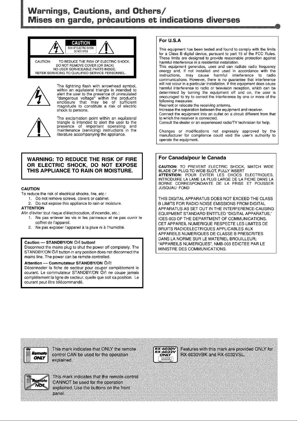
CAUTION: TO REDUCE THE RISK OF ELECTRIC SHOCK.
REFER SERVICING TO QUALIFIED SERVICE PERSONNEL.
DO NOT REMOVE COVER {OR BACK)
NO USER SERVICEABLE PARTS INSIDE.
The lightning flash with arrowhead symbol,
within an equilateral triangle is intended to
alert the user to the presence of uninsulated
"dangerous voltage" within the product's
enclosure that may be of sufficient
magnitude to constitute a risk of electric
shock to persons.
The exclamation point within an equilateral
triangle is intended to alert the user to the
presence of important operating and
maintenance (servicing) instructions in the
literature accompanying the appliance.
For U.S.A
This equipment has been tested and found to comply with the limits
for a Class B digital device, pursuant to part 15 of the FCC Rules.
These limits are designed to provide reasonable protectio_l against
harmful interference in a residential installation.
This equipment generates, uses and can radiate radio frequency
energy and, if not installed and used in accordance with the
instructions, may cause harmful interference to radio
communications. However, there is no guarantee that interference
will not occur in a particular installation. If this equipment does cause
harmful interference to radio or televisio_l reception, which can be
determined by turning the equipment off and on, the user is
encouraged to try to correct the interference by one or more of the
following measures:
Reorient or relocate the receiving antenna.
Increase the separation between the equipment and receiver.
Connect the equipment into an outlet on a circuit different from that
to which the receiver is connected.
Consult the dealer or an experienced radio/TV technician for help.
Changes or modifications not expressly approved by the
manufacturer for compliance could void the user's authority to
operate the equipment.
WARNING: TO REDUCE THE RISK OF FIRE
OR ELECTRIC SHOCK, DO NOT EXPOSE
THIS APPLIANCE TO RAIN OR MOISTURE.
I
CAUTION
To reduce the risk of electrical shocks, fire, etc.:
1. Do not remove screws, covers or cabinet.
2. Do not expose this appliance to rain or moisture.
ATTENTION
Afin d'eviter tout risque d'_lectrocution, d'incendie, etc.:
t. Ne pas enlever tes vis nites panneaux et ne pas ouvrir le
coffret de I'appareil.
2. Ne pas exposer I'appareil &la pluie ni & t'humidit&
Caution i STANDBY/ON d_/I button!
Disconnect the mains plug to shut the power off completely. The
STANDBY/ON O/I button in any position does not disconnect the
mains line. The power can be remote controlled.
Attention -- Commutateur STANDBY/ON 0)/1!
D_connecter ta fiche de secteur pour couper compl_tement te
courant. Le commutateur STANDBY/ON O/I ne coupe jamais
compt_tement la tigne de secteur, quelle que suit sa position. Le
courant peut 6tre t_l_command&
For Canad_pourle Canada
CAUTION: TO PREVENT ELECTRIC SHOCK, MATCH WIDE
BLADE OF PLUG TO WIDE SLOT, FULLY INSERT
ATTENTION: POUR EVlTER LES CHOCS ELECTRIQUES,
INTRODUlRE LA LAME LA PLUS LARGE DE LA FICHE DANS LA
BORNE CORRESPONDANTE DE LA PRISE ET POUSSER
JUSQUAU FOND
THIS DIGITAL APPARATUS DOES NOT EXCEED THE CLASS
B LIMITS FOR RADIO NOISE EMISSIONS FROM DIGITAL
APPARATUS AS SET OUT IN THE INTERFERENCE-CAUSING
EQUIPMENT STANDARD ENTITLED "DIGITAL APPARATUS,"
ICES-003 OF THE DEPARTMENT OF COMMUNICATIONS.
CET APPAREIL NUMERIQUE RESPECTE LES LIMITES DE
BRUITS RADIOELECTRIQUES APPLICABLES AUX
APPAREILS NUMERIQUES DE CLASSE B PRESCRITES
DANS LA NORME SUR LE MATERIEL BROUILLEUR;
"APPAREILS NUMERIQUES', NMB-O03 EDICTEE PAR LE
MINISTRE DES COMMUNICATIONS.
Page 3
Parts Identification ...................................... 2
Getting Started ........................................... 5
Before Installation ............................................................. 5
Checking the Supplied Accessories ................................. 5
Connecting the AM and FM Antennas ............................. 5
Connecting the Speakers and Subwoofer ........................ 6
Connecting Audio/Video Components .............................. 7
Analog Connections................................................................. 7
Digital Connections ................................................................ 10
Connecting the Power Cord ........................................... 10
Putting Batteries in the Remote Control ......................... 10
Basic Operations ....................................... 1 1
Turning On the Power ..................................................... 11
Selecting the Source to Play .......................................... 11
Changing the Source Name ........................................... 12
Selecting Different Sources for Picture and Sound ........ 12
Adjusting the Volume ...................................................... 13
Listening with Headphones Only .................................... 13
Turning Off the Sound Temporarily--Muting ................... 13
Changing the Display Brightness--DIMMER ................. 13
Turning Off the Power with the Sleep Timer ................... 14
Basic Settings ........................................... 1 5
Basic Settings Using MULTI JOG Dial ........................... 15
Setting the Speaker Information ............................................ 15
Selecting the Digital InputTerminals--DIGITAL IN ................ 16
Selecting the Video InputTerminal--
VIDEO IN DVD,VIDEO INVCR....................................... 16
Selecting the Analog or Digital Input Mode .................... 17
Sound Adjustments .................................... 18
Attenuating the Input Signal ........................................... 18
Turning Off the Subwoofer .............................................. 18
Reinforcing the Bass ...................................................... 18
Sound Adjustments Using MULTI JOG Dial ................... 19
Sound Adjustments Using Remote Control .................... 20
Adjusting Speaker Output LevelsUsingTestTone................. 20
Adjusting Subwoofer OutputLevel......................................... 21
Tuner Operations ....................................... 22
Tuning in to Stations Manually ........................................ 22
Using Preset Tuning ....................................................... 22
ToStorethe Preset Stations .................................................. 22
ToTune in to a Preset Station ................................................ 23
Selecting the FM Reception Mode ................................. 23
Creating Realistic Sound Fields ................... 24
Using Surround Modes ................................................... 26
Using DSP Modes .......................................................... 27
Using DVD MULTI Playback Mode
(RX-6030VBK/RX-6032VSL only) ........... 28
Activating DVD MULTI Playback Mode ........................... 28
COMPU LINK Remote Control System ......... 29
AV COMPU LINK Remote Control System .... 30
Operating JVC's Audio/Video
Components .......................................... 32
Operating Audio Components ........................................ 32
Operating Video Components ........................................ 34
Operating Other Manufacturers' Video
Equipment ............................................ 35
Troubleshooting ......................................... 37
Specifications ............................................ 38
m
=
=I
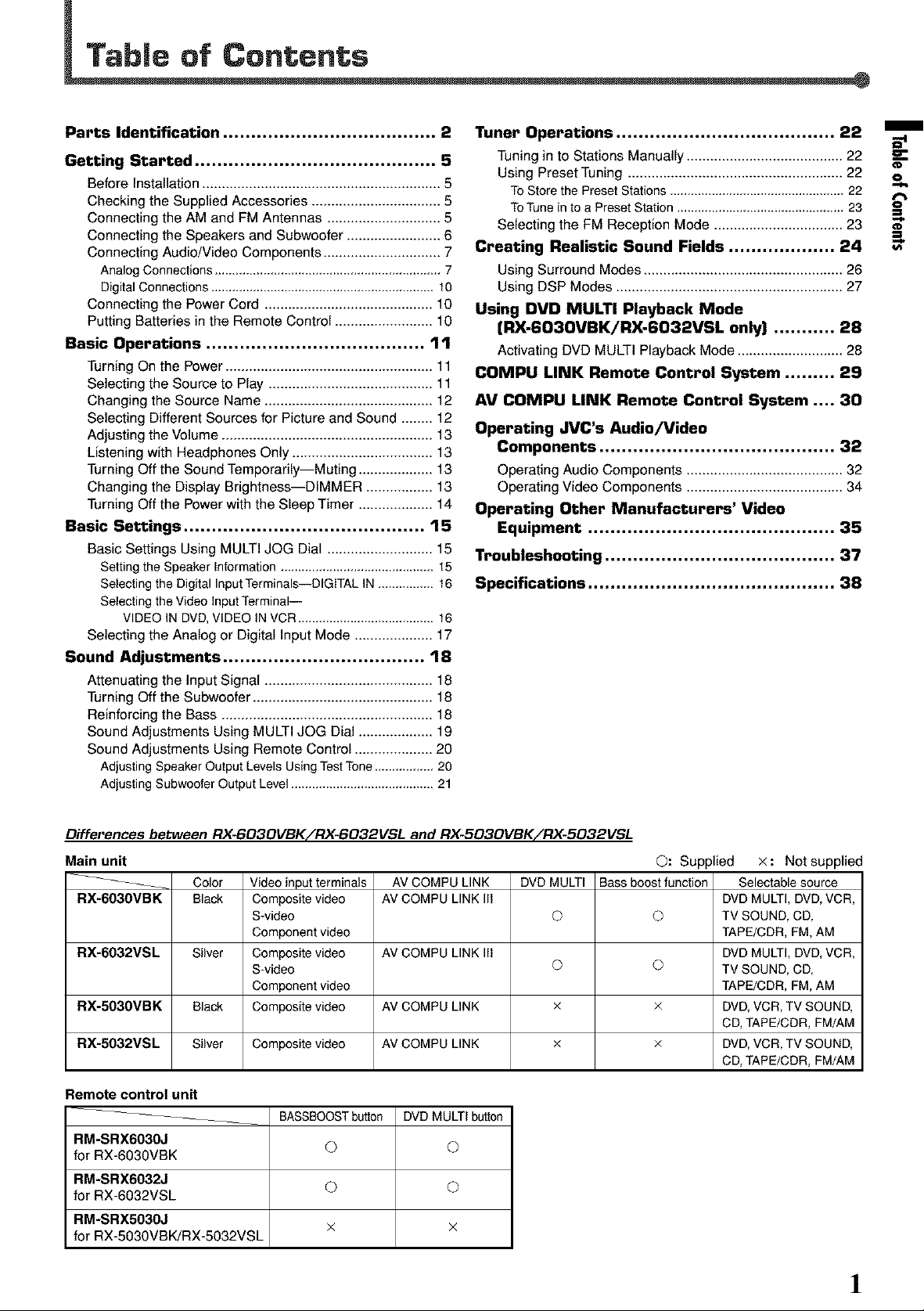
Differences between RX-6030VBKiRX-6032VSL and RX-503OVBKiRX-5032VSL
Main unit ©: Supplied
__ Bass boostfunction
RX-603OVBK
RX-6032VSL
RX-5030VBK x ×
RX-5032VSL Composite video x ×
Color
Black
Silver
Black
Silver
Video input terminals
Composite video
S-video
Component video
Composite video
S-video
Component video
Composite video
AV COMPU LINK
AV COMPU LINK Ill
AV COMPU LINK Ill
AV COMPU LINK
AV COMPU LINK
DVDMULTI
©
© ©
©
Remote control unit
__ BASSBOOSTbutton DVDMULTIbutton
RM-SRX603OJ © ©
for RX-603OVBK
RM-SRX6032J © ©
for RX-6032VSL
RM-SRX503OJ
for RX-5030VBK/RX-5032VSL
X X
x: Not supplied
Selectable source
DVD MULTI, DVD, VCR,
TV SOUND, CD,
TAPE/CDR, FM, AM
DVD MULTI, DVD, VCR,
TV SOUND, CD,
TAPE/CDR, FM, AM
DVD, VCR, TV SOUND,
CD, TAPE/CDR, FM/AM
DVD, VCR, TV SOUND,
CD, TAPE/CDR, FM/AM
!
Page 4
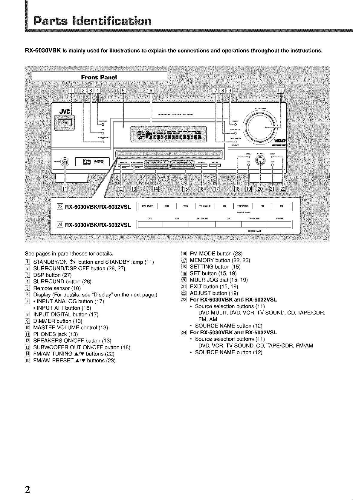
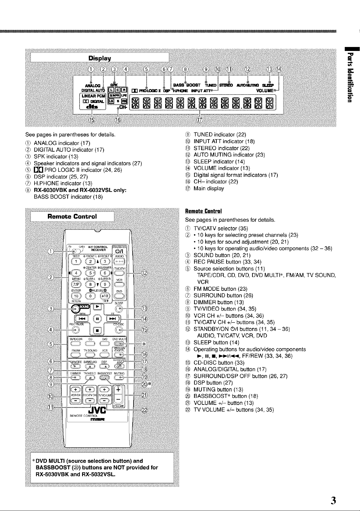
RX-6030VBK is mainly used for illustrations to explain the connections and operations throughout the instructions.
See pages in parentheses for details.
I1_ STANDBY/ON _/I button and STANDBY lamp (11)
I_ SURROUND/DSP OFF button (26, 27)
I_1 DSP button (27)
141SURROUND button (26)
151Remote sensor (10)
161Display (For details, see "Display" on the next page.)
ITL • INPUT ANALOG button (17)
• INPUT ATT button (18)
181INPUT DIGITAL button (17)
19_DIMMER button (13)
I_0_MASTER VOLUME control (13)
lill PHONES jack (13)
I;2_SPEAKERS ON/OFF button (13)
1_31SUBWOOFER OUT ON/OFF button (18)
1_4_FM/AM TUNING A/v buttons (22)
I;5LFM/AM PRESET A/_" buttons (23)
/f6l FM MODE button (23)
/f?l MEMORY button (22, 23)
/fS] SETTING button (15)
i9 SET button (15, 19)
/20l MULTI JOG dial (15, 19)
/2;1EXIT button (15, 19)
/221ADJUST button (19)
/z3 For RX-6030VBK and RX-6032VSL
• Source selection buttons (11)
DVD MULTI, DVD, VCR, TV SOUND, CD, TAPE/CDR,
FM, AM
• SOURCE NAME button (12)
/24 For RX-5030VBK and RX-5032VSL
• Source selection buttons (11)
DVD, VCR, TV SOUND, CD, TAPE/CDR, FM/AM
• SOURCE NAME button (12)
2
Page 5
m
E
See pages in parentheses for details.
Q_ ANALOG indicator (17)
_2_DIGITAL AUTO indicator (17)
_3_SPK indicator (13)
_4_Speaker indicators and signal indicators (27)
_5_1"3['1PRO LOGIC II indicator (24, 26)
_6_DSP indicator (25, 27)
_7_H.PHONE indicator (13)
_8_RX-6030VBK and RX-6032VSL only:
BASS BOOST indicator (18)
iii iiii:i
'iii!'i i ii ii?i! i!iii i
ii i i !i! o ii!,ili!i!,ii!i
ili_iiii_i_ii!_i_ili!i!_i_ii!ii!i,i!iiiiii_i_iiil_!io_ooToc.To ii!iiiiiiiiii!iiii_i!i_iii!iii!!ii!i_i_i!iiii_!i!i_ili:i!ili_ii
_9_TUNED indicator (22)
_ INPUT ATT indicator (18)
_ STEREO indicator (22)
_2_AUTO MUTING indicator (23)
_ SLEEP indicator (14)
_-_ VOLUME indicator (13)
L_ Digital signal format indicators (17)
_ CH- indicator (22)
@ Main display
RemoteControl
See pages in parentheses for details.
_ TV/CATV selector (35)
_2_• 10 keys for selecting preset channels (23)
• 10 keys for sound adjustment (20, 21)
• 10 keys for operating audio/video components (32 - 36)
_3_SOUND button (20, 21)
_4_REC PAUSE button (33, 34)
_5_Source selection buttons (11)
TAPE/CDR, CD, DVD, DVD MULTI _, FM/AM, TV SOUND,
VCR
_6_FM MODE button (23)
_7_SURROUND button (26)
_8_DIMMER button (13)
_9_TV/VIDEO button (34, 35)
_ VCR CH +/- buttons (34, 36)
_ TV/CATV CH +/- buttons (34, 35)
_-2_STANDBY/ON (b/I buttons (11, 34-36)
AUDIO, TV/CATV, VCR, DVD
_ SLEEP button (14)
_-_ Operating buttons for audio/video components
_, H, m, J,_4/_, FF/REW (33, 34, 36)
_ CD-DISC button (33)
_ ANALOG/DIGITAL button (17)
@ SURROUND/DSP OFF button (26, 27)
@ DSP button (27)
_ MUTING button (13)
BASSBOOST • button (18)
@ VOLUME +/-button (13)
_ TV VOLUME +/- buttons (34, 35)
.............. .........................................................................................
3
Page 6
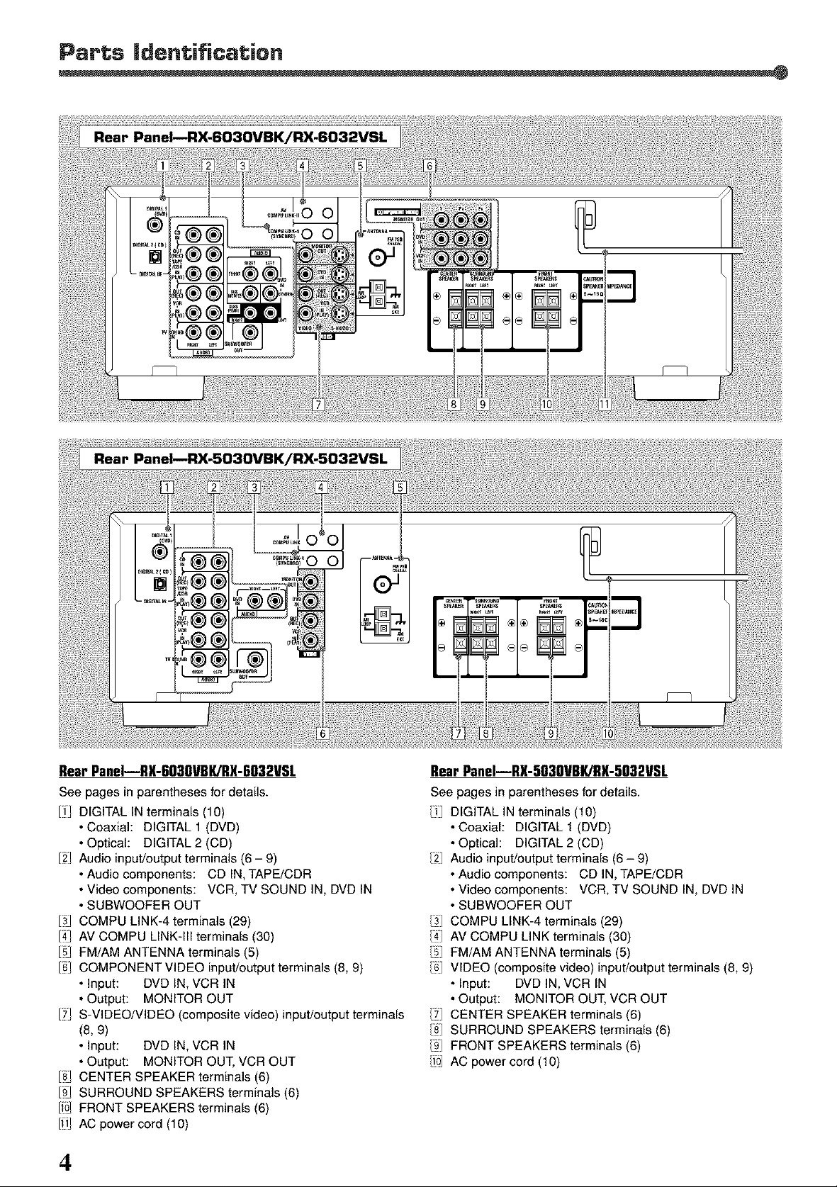
Rear PaneI--RX-6030VBK/RX-6032VSL
See pages in parentheses for details.
II/ DIGITAL IN terminals (10)
• Coaxial: DIGITAL 1 (DVD)
• Optical: DIGITAL 2 (CD)
12LAudio input/output terminals (6 - 9)
• Audio components: CD IN, TAPE/CDR
• Video components: VCR, TV SOUND IN, DVD IN
• SUBWOOFER OUT
I_1 COMPU LINK-4 terminals (29)
14] AV COMPU LINK-Ill terminals (30)
151FM/AM ANTENNA terminals (5)
16/ COMPONENT VIDEO input/output terminals (8, 9)
• Input: DVD IN, VOR IN
• Output: MONITOR OUT
17LS-VIDEO/VIDEO (composite video) input/output terminals
(8, 9)
• Input: DVD IN, VCR IN
• Output: MONITOR OUT, VCR OUT
18] CENTER SPEAKER terminals (6)
19J SURROUND SPEAKERS terminals (6)
IloJ FRONT SPEAKERS terminals (6)
Ill] AC power cord (10)
4
Rear PaneI--RX-5030VBK/RX-5032VSL
See pages in parentheses for details.
[i DIGITAL IN terminals (10)
• Coaxial: DIGITAL 1 (DVD)
• Optical: DIGITAL 2 (CD)
/2 Audio input/output terminals (6 - 9)
• Audio components: CD IN, TAPE/CDR
• Video components: VCR, TV SOUND IN, DVD IN
• SUBWOOFER OUT
/3] COMPU LINK-4 terminals (29)
/4] AV COMPU LINK terminals (30)
/_J FM/AM ANTENNA terminals (5)
/6 VIDEO (composite video) input/output terminals (8, 9)
• Input: DVD IN, VCR IN
• Output: MONITOR OUT, VCR OUT
/YI CENTER SPEAKER terminals (6)
/8] SURROUND SPEAKERS terminals (6)
/gJ FRONT SPEAKERS terminals (6)
/i0 AC power cord (10)
Page 7
I
General Precautions
• DO NOT insert any metal object intothe unit.
• DO NOT disassemble the unit or remove screws, covers, or
cabinet.
• DO NOT expose the unit to rain or moisture.
Locations
• Install the unit in a location that is level and protected from
moisture.
• The temperature around the unit must be between -5°C and
35°C (23"F and 95"F).
• Make sure there ls good ventilation around the unit. Poor
ventilation could cause overheating and damage the unit.
Handling the unit
• DO NOT touch the power cord with wet hands.
• DO NOT pull on the power cord to unplug the cord. When
unplugging the cord, always grasp the plug so as not to -ANTEHNA--
damage the cord. F,,gol
• Keep the power cord away from the connecting cords and C0AX_L
the antenna. The power cord may cause noise or screen
interference. Coaxial cable is recommended for the antenna
connection, since such cable is well-shielded against
interference.
• When a power failure occurs, or when you unplug the power _ _
cord, the preset settings such as preset FM or AM channels
and sound adjustments may be erased within a few days. I
[
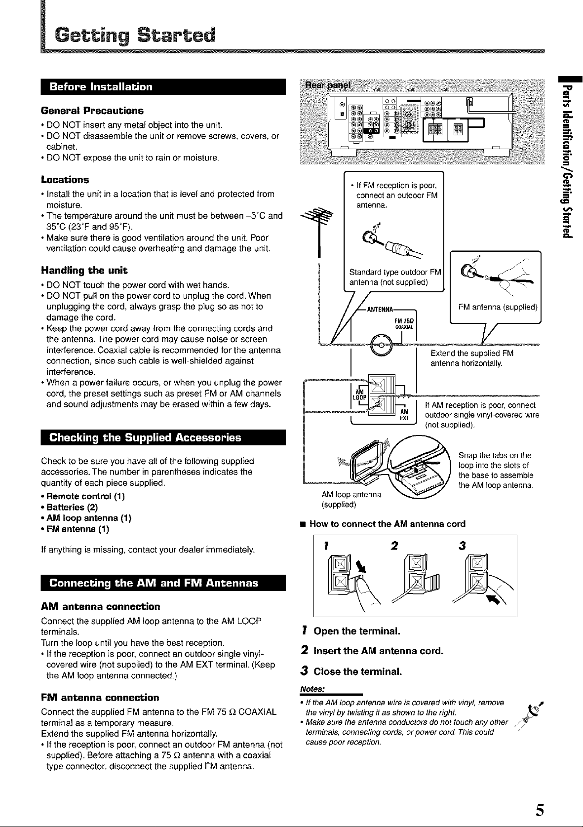
• If FM reception is poor,
connect an outdoor FM
antenna.
Standardtype outdoor FM
antenna (not supplied)
I
L
J
=.
FM antenna (supplied)
F
Extend the supplied FM
antenna horizontally.
If AM reception is poor, connect
outdoor single vinyl-covered wire
(not supplied).
Check to be sure you have all of the following supplied
accessories. The number in parentheses indicates the
quantity of each piece supplied.
• Remote control (1)
• Batteries (2)
• AM loop antenna (1)
• FM antenna (1)
If anything is missing, contact your dealer immediately.
AM antenna connection
Connect the supplied AM loop antenna to the AM LOOP
terminals.
Turn the loop until you have the best reception.
• If the reception is poor, connect an outdoor single vinyl-
covered wire (not supplied) to the AM EXT terminal. (Keep
the AM loop antenna connected.)
FMantenna connection
Connect the supplied FM antenna to the FM 75 _ COAXIAL
terminal as a temporary measure.
Extend the supplied FM antenna horizontally.
• If the reception is poor, connect an outdoor FM antenna (not
supplied). Before attaching a 75 _ antenna with a coaxial
type connector, disconnect the supplied FM antenna.
Snap the tabs on the
loop into the stots of
the base to assembte
the AM loop antenna.
AM loop antenna
(supplied)
• How to connect the AM antenna cord
! 2 3
1 Open the terminal.
2 Insert the AM antenna cord.
3 Close the terminal.
Notes:
• If the AM loop antenna wire is covered with vinyl, remove ,.t
the vinyl by twistingit as shown to theright.
• Make sure the antenna conductors do not touch any other
terminals, connecting cords, or power cord. Thiscould
cause poor reception.
5
Page 8
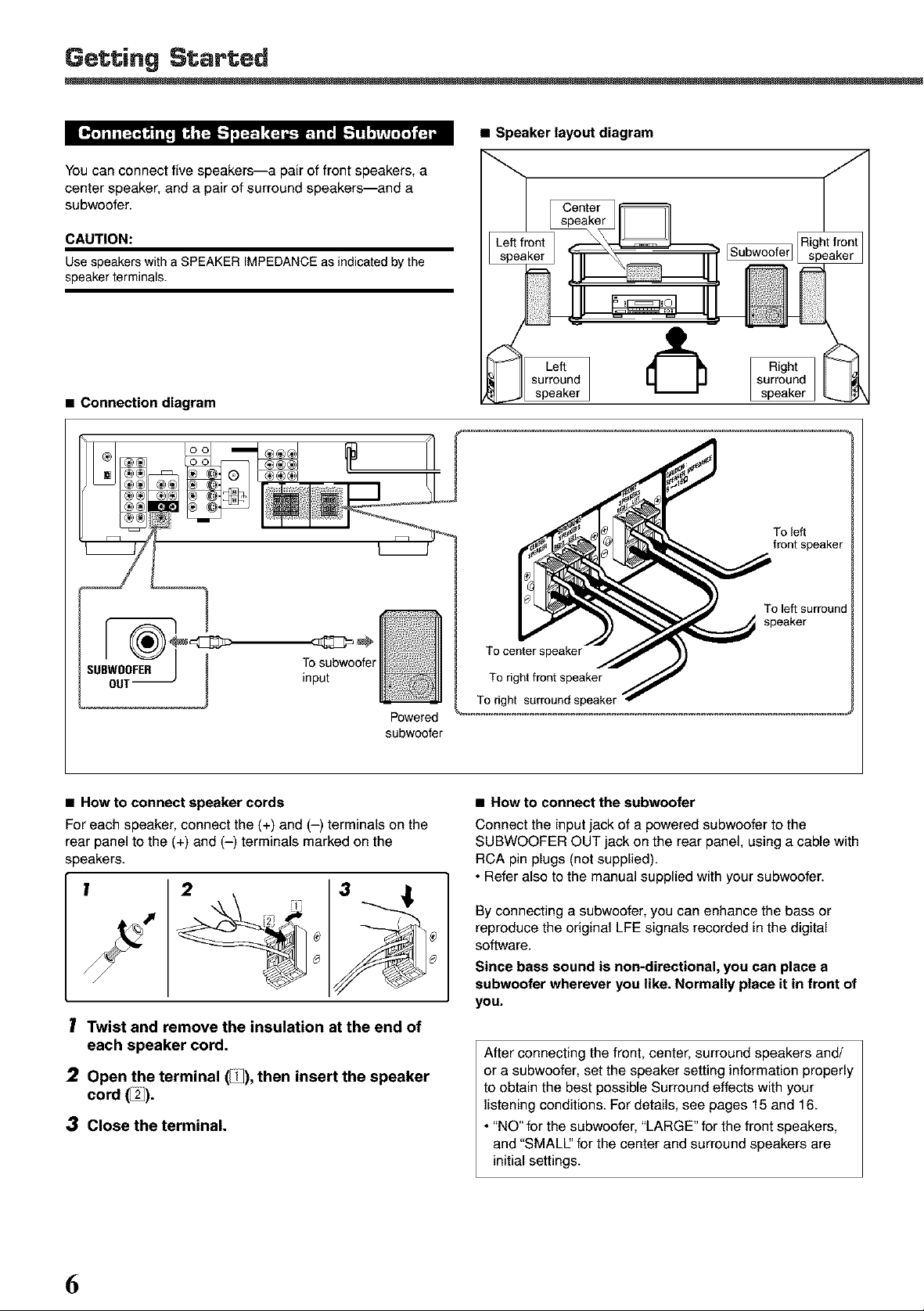
You can connect five speakers--a pair of front speakers, a
center speaker, and a pair of surround speakers--and a
subwoofer.
CAUTION:
Usespeakers with aSPEAKER IMPEDANCE as indicated bythe
speaker terminals.
• Connection diagram
• Speaker layout diagram
To left
front speaker
To subwoofer
input
Powered
subwoo_r
• How to connect speaker cords
For each speaker, connect the (+) and (-) terminals on the
rear panel to the (+) and (-) terminals marked on the
speakers.
3
I Twist and remove the insulation at the end of
each speaker cord.
2 Open the terminal _), then insert the speaker
cord(%).
3 Close the terminal.
To left surround
speaker
To center speaker
To right front speaker
To right surround speaker
• How to connect the subwoofer
Connect the input jack of a powered subwoofer to the
SUBWOOFER OUT jack on the rear panel, using a cable with
RCA pin plugs (not supplied).
• Refer also to the manual supplied with your subwoofer.
By connecting a subwoofer, you can enhance the bass or
reproduce the original LFE signals recorded in the digital
software.
Since bass sound is non-directional, you can place a
subwoofer wherever you like. Normally place it in front of
yOU.
After connecting the front, center, surround speakers and/
or a subwoofer, set the speaker setting information properly
to obtain the best possible Surround effects with your
listening conditions. For details, see pages 15 and 16.
• "NO" for the subwoofer, "LARGE" for the front speakers,
and "SMALl" for the center and surround speakers are
initial settings.
6
Page 9
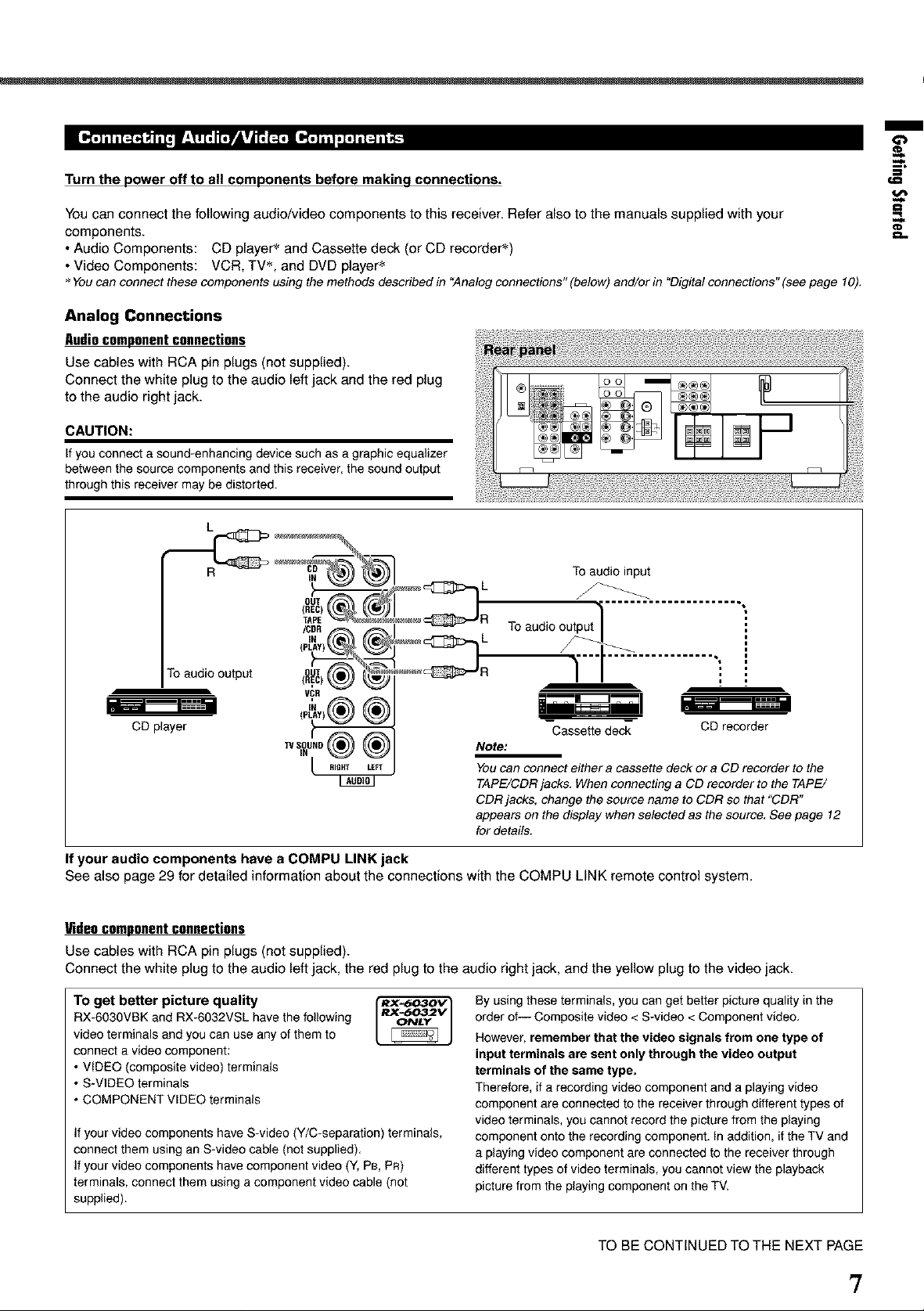
Turn the power off to all components before making connections.
You can connect the following audio/video components to this receiver. Refer also to the manuals supplied with your
components.
• Audio Components: CD player _ and Cassette deck (or CD recorder s)
• Video Components: VCR, TV_, and DVD player _
Youcan connect these components using the methods described in "Analog connections" (below) and/or in "Digitalconnections" (seepage 10).
Analog Connections
Audiocomponent connections
Use cables with RCA pin plugs (not supplied).
Connect the white plug to the audio left jack and the red plug
to the audio right jack.
CAUTION:
If you connect a sound-enhancing device such as a graphic equalizer
between the source components and this receiver, the sound output
through this receiver may be distorted.
m
_--%
==
R
To audio output]
To audio output
CD player
Note:
You can connect either a cassette deck or a CD recorder to the
TAPE/CDR jacks. When connecting a CD recorder to the TAPE/
CDR jacks, change the source name to CDR so that "CDR"
appears on the display when selected as the source, See page 12
for details.
To audio input
-Cassette dec_ CD recorder
If your audio components have a COMPU LINK jack
See also page 29 for detailed information about the connections with the COMPU LINK remote control system.
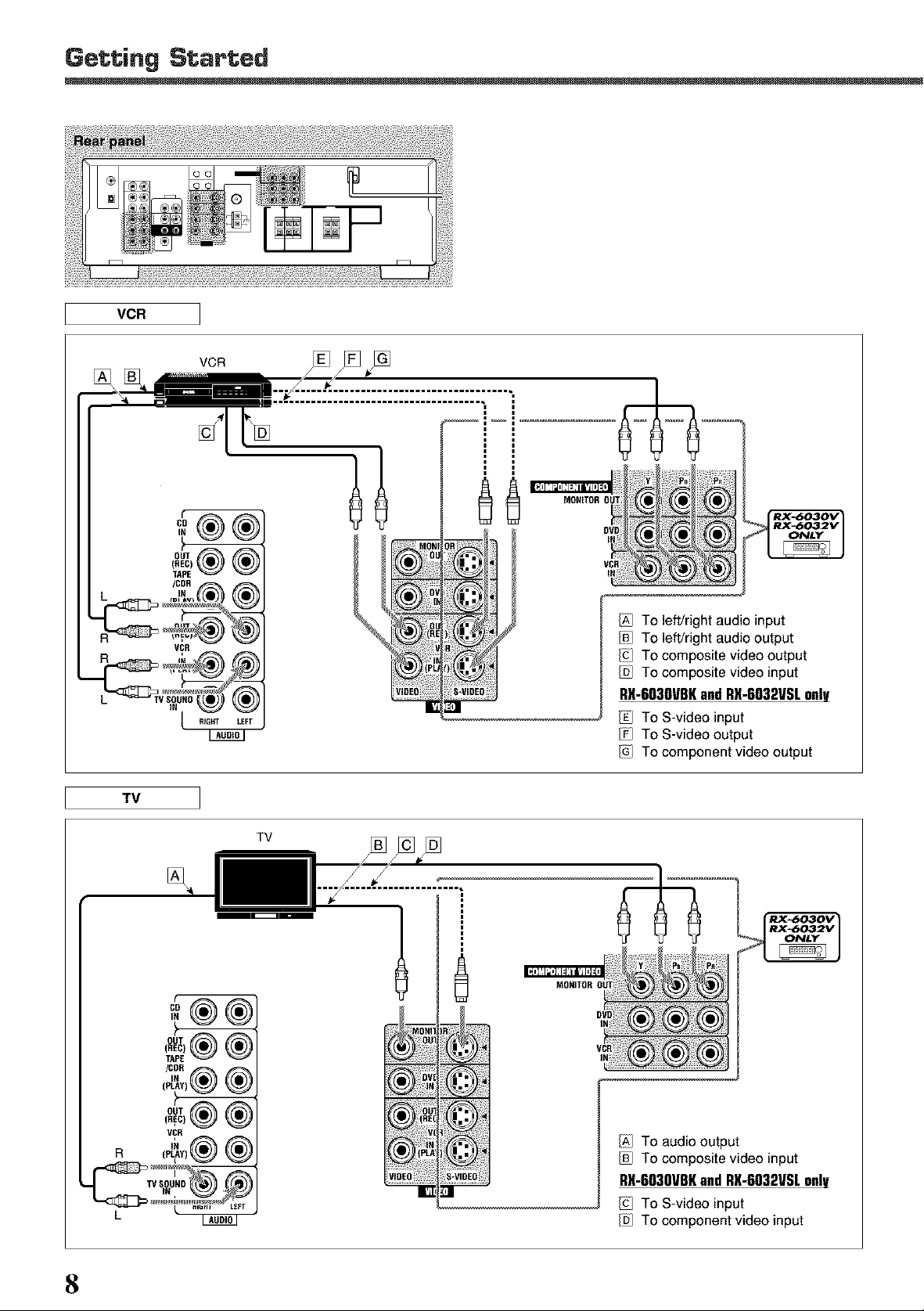
Video component connections
Use cables with RCA pin plugs (not supplied).
Connect the white plug to the audio left jack, the red plug to the audio right jack, and the yellow plug to the video jack.
To get better picture quality
RX-6030VBK and RX-6032VSL have the following
video terminals and you can use any of them to
connect a video component:
• VIDEO (composite video) terminals
• S-VIDEO terminals
• COMPONENT VIDEO terminals
If your video components have S-video (Y/C-separation) terminals,
connect them using an S-video cable (not supplied).
If your video components have component video (Y, PB, PR)
terminals, connect them using a component video cable (not
supplied).
RX-6032V
ONLY
By using these terminals, you can get better picture quality in the
order of-- Composite video < S-video < Component video.
However, remember that the video signals from one type of
input terminals are sent only through the video output
terminals of the same type.
Therefore, if a recording video component and a playing video
component are connected to the receiver through different types of
video terminals, you cannot record the picture from the playing
component onto the recording component. In addition, if the TV and
a playing video component are connected to the receiver through
different types of video terminals, you cannot view the playback
picture from the playing component on the TV.
TO BE CONTINUED TO THE NEXT PAGE
7
Page 10
Getting Started
® o o iii
VCR
TV
IX] To left/right audio input
VCR
TV
....x-_/IDE(
[]
To left/right audio output
To composite video output
To composite video input
RX-603OVBKand RX-6032VSL only
To S-video input
To S-video output
To component video output
[]
MO_I
_OU
8
i_)[0v
IX] To audio output
To composite video input
RX-6030VBK and RX-6032VSL onlV
To S-video input
To component video input
Page 11
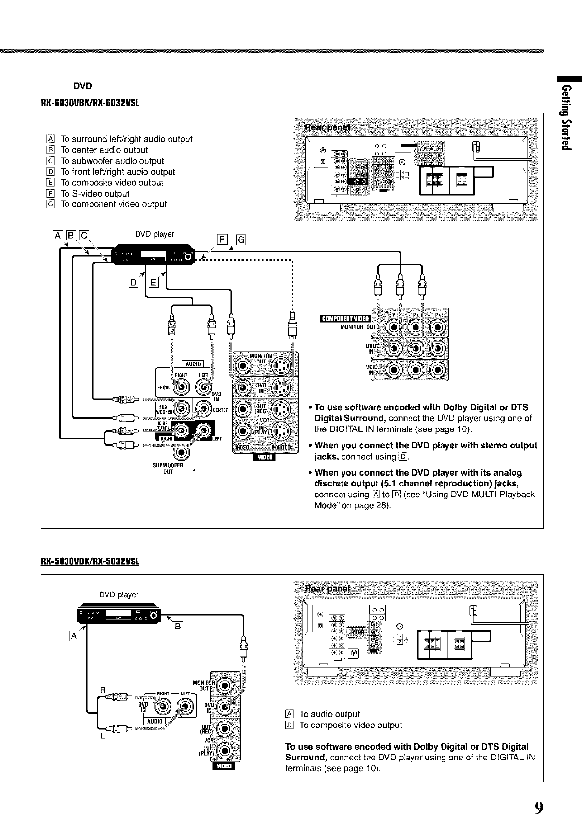
DVD
RX-6030VBKiRX-6032VSL
/A1 To surround left/right audio output
To center audio output
To subwoofer audio output
To front left/right audio output
To composite video output
To S-video output
To component video output
m
€81
RX-5030VBI(/RX-5032VSL
DVD player
$U8
SUBWOOFER
OUT--
• To use software encoded with Dolby Digital or DTS
Digital Surround, connect the DVD player using one of
the DIGITAL IN terminals (see page 10).
• When you connect the DVD player with stereo output
jacks, connect using _.
• When you connect the DVD player with its analog
discrete output (5.1 channel reproduction) jacks,
connect using/A] to _ (see "Using DVD MULTI Playback
Mode" on page 28).
/AI TOaudio output
To composite video output
To use software encoded with Dolby Digital or DTS Digital
Surround, connect the DVD player using one of the DIGITAL IN
terminals (see page 10).
9
Page 12
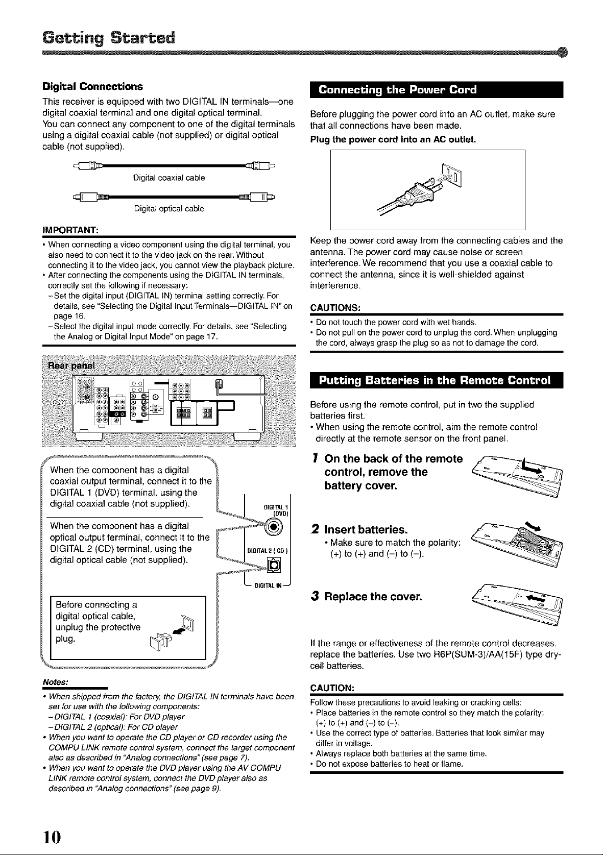
Digital Connections
This receiver is equipped with two DIGITAL IN terminals_ne
digital coaxial terminal and one digital optical terminal.
You can connect any component to one of the digital terminals
using a digital coaxial cable (not supplied) or digital optical
cable (not supplied).
Digital coaxial cable
Digital optical cable
IM PORTANT:
• When connecting a video component using the digital terminal, you
also need to connect it to the video jack on the rear. Without
connecting it to the video jack, you cannot view the playback picture.
• After connecting the components using the DIGITAL IN terminals,
correctly set the following if necessary:
-Set the digital input (DIGITAL IN) terminal setting correctly. For
details, see "Selecting the Digital Input Terminals--DIGiTAL IN" on
page 16.
-Select the digital input mode correctly. For details, see "Selecting
the Analog or Digital Input Mode" on page 17.
Before plugging the power cord into an AC outlet, make sure
that all connections have been made.
Plug the power cord into an AC outlet.
Keep the power cord away from the connecting cables and the
antenna. The power cord may cause noise or screen
interference. We recommend that you use a coaxial cable to
connect the antenna, since it is well-shielded against
interference.
CAUTIONS:
• Do not touch the power cord with wet hands.
• De net pull on thepower cordto unplug the cord.When unplugging
the cord, alwaysgrasp the plug so as net to damage the cord.
When the component has a digital
coaxial output terminal, connect it to the_
DIGITAL 1 (DVD) terminal, using the _ I
digital coaxial cable (not supplied). _ I SiGITAL1
When the component has a digital _o_fa_t
optical output terminal, connect it to the _ /
DIGITAL 2 (CD) terminal, using the [_, ISlGITAL2(CO)
digital optical cable (not supplied). _
_ L_DIGITAL _
Before connecting a
unplug the protective
digital optica, cab,e, _
plug.
Notes:
• When shipped from the factory, the DIGITAL IN terminals have been
set for use with the following components:
-DIGITAL 1 (coaxial): For DVD player
-DIGITAL 2 (optical): For CD player
• When you want to operate the CD player or CD recorder using the
COMPU LINK remote control system, connect the target component
also as described in "Analog connections" (see page 7).
• When you want to operate the DVD player using the AV COMPU
LINK remote control system, connect the DVD player also as
described in '_Analog connections" (see page 9).
Before using the remote control, put in two the supplied
batteries first.
• When using the remote control, aim the remote control
directly at the remote sensor on the front panel.
l! On the back of the remote F_--_i---_
battery cover.
control, remove the _
2 Insert batteries.
• Makesure to match the polarity:
(+)to (+) and (-) to (-).
3 Replace the cover.
If the range or effectiveness of the remote control decreases,
replace the batteries. Use two R6P(SUM-3)/AA(15F) type dry-
cell batteries.
CAUTION:
Follow these precautions to avoid leaking or cracking cells:
• Place batteries in the remote control so they match the polarity:
(+) to (+) and (-) to (-).
• Use the correct type of batteries. Batteries that look similar may
differ in voltage.
• Always replace both batteries at the same time.
• De net expose batteries to heat or flame.
10
Page 13
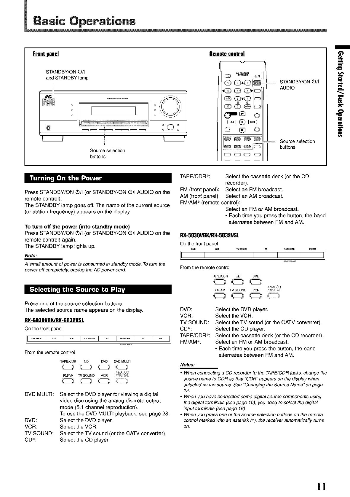
F_ Remote control
STANDBY/ON Oil
and STANDBY lamp
Q Q'Q_
',Q Q Q,'<_
®
o o
o o
.......... O
° L °
• _ o o
Source selection
buttons
°O °
QQO_
@@@@
oooo
L STANDBY/ON d_/I
AUDIO
,---_ Source selection
buttons
m
I:1
t#l
O
=_,.
5"
|t!_l [']11B I_!1 "."?P/F4_
Press STANDBY/ON doll (or STANDBY/ON doll AUDIO on the
remote control).
The STANDBY lamp goes off. The name of the current source
(or station frequency) appears on the display.
To turn off the power (into standby mode)
Press STANDBY/ON dOll(or STANDBY/ON dOllAUDIO on the
remote control) again.
The STANDBY lamp lights up.
Note:
A small amount of power is consumed in standby mode. To turn the
power off completely, unplug the AC power cord.
Press one of the source selection buttons.
The selected source name appears on the display.
RX-603OVBKiRX-6032VSL
On the front panel
ooi o i -ol o i.... i o i o II
From the remote control
TAPE/CDR CD DVD DVD MULTI
DVD MULTI:
DVD:
VCR:
TV SOUND:
CD_:
0000
FM/AM TV SOUND VCR ;)IGi A
0 0 0
Select the DVD player for viewing a digital
video disc using the analog discrete output
mode (5.1 channel reproduction).
To use the DVD MULTI playback, see page 28.
Select the DVD player.
Select the VCR.
Select the TV sound (or the CATV converter).
Select the CD player.
AAJO
TAPE/CDR_: Select the cassette deck (or the CD
recorder).
FM (front panel): Select an FM broadcast.
AM (front panel): Select an AM broadcast.
FM/AM _ (remote control):
Select an FM or AM broadcast.
• Each time you press the button, the band
alternates between FM and AM.
RX-5030VBI(iRX-5032VSL
On the front panel
[i i i i i i i]
From the remote control
TAPE/CDR CD DVD
000
FMJAM TV SOUND VCR _}GIX
000
DVD: Select the DVD player.
VCR: Select the VCR.
TV SOUND: Select the TV sound (or the CATV converter).
CD_: Select the CD player.
TAPE/CDR_: Select the cassette deck (or the CD recorder).
i
FM/AM_: Select an FM or AM broadcast.
• Each time you press the button, the band
alternates between FM and AM.
Notes:
• When connecting a CD recorder to the TAPE/CDR jacks, change the
source name to CDR so that "CDR" appears on the display when
selected as the source. See "Changing the Source Name" on page
12.
• When you have connected some digital source components using
the digital terminals (see page 10), you need to select the digital
input terminals (see page 16),
• When you press one of the source selection buttons on the remote
control marked with an asterisk (_), the receiver automatically turns
on,
ANAl eG
]!
Page 14
Basic Operations
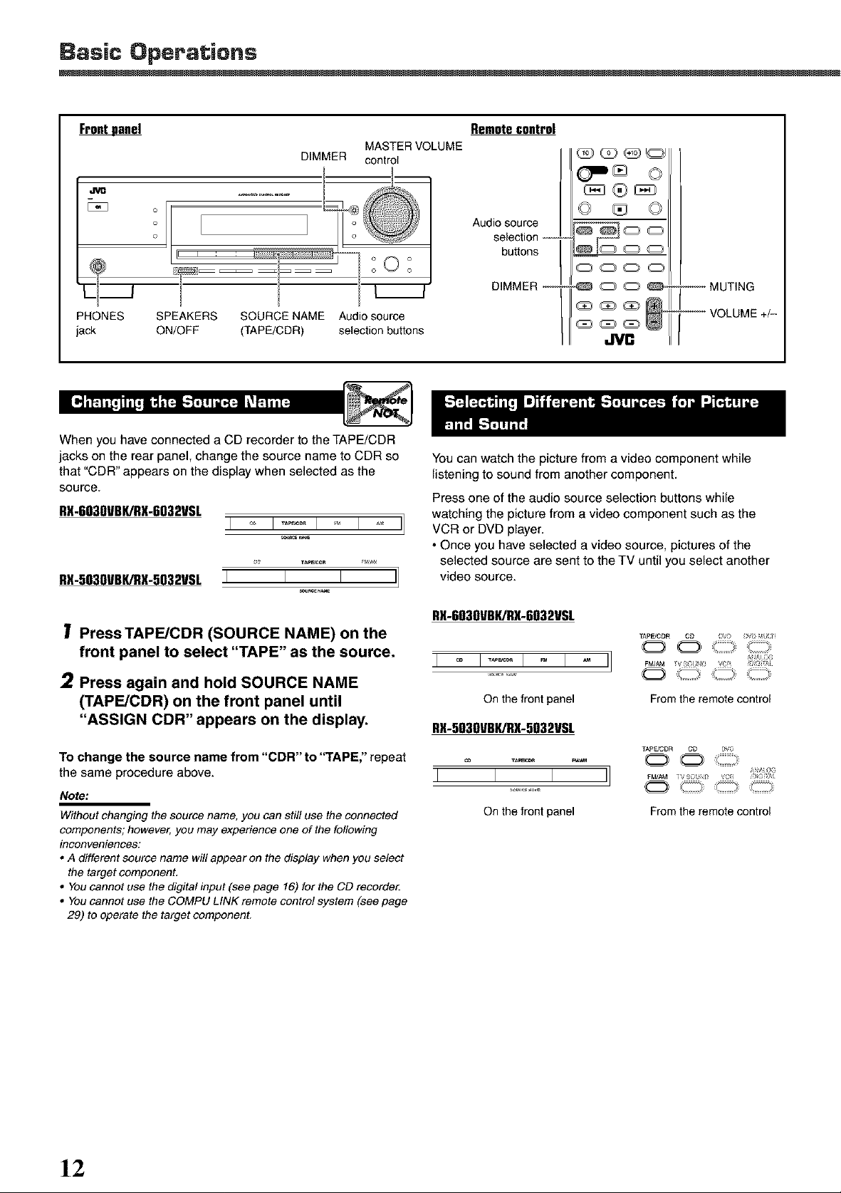
F_ Remotecontrol
DIMMER control
MASTER VOLUME
Audio source
selection -_-
buttons
PHONES
jack
SPEAKERS SOURCE NAME Audio source
ON/OFF (TAPE/CDR) selection buttons
When you have connected a CD recorder to the TAPE/CDR
jacks on the rear panel, change the source name to CDR so
that "CDR" appears on the display when selected as the
source.
RX-6030VBK/RX-6032VSL
I _ I ..... I ' I I]
RX-5030VBK/RX-5032VSLI I I I]
Press TAPEJCDR (SOURCE NAME) on the
front panel to select "TAPE" as the source,
2 Press again and hold SOURCE NAME
(TAPE/CDR) on the front panel until
"ASSIGN CDR" appears on the display.
To change the source name from "CDR" to "TAPE," repeat
the same procedure above.
Note:
Without changing the source name, you can still use the connected
components; however, you may experience one of the following
inconveniences:
• A different source name will appear on the display when you select
the target component,
• You cannot use the digital input (see page 16) for the CD recorde_
• You cannot use the COMPU LINK remote control system (see page
29) to operate the target component.
DIMMER --
-- MUTING
VOLUME +/-
You can watch the picture from a video component while
listening to sound from another component.
Press one of the audio source selection buttons while
watching the picture from a video component such as the
VCR or DVD player.
• Once you have selected a video source, pictures of the
selected source are sent to the TV until you select another
video source.
RX-6030VBIURX-6032VSL
I _ I ...... I., I _, II
On the trent panel
O
From the remote control
RX-5030VBK/RX-5032VSL
TAp_ICDR CD _V_i
0 0
0 " '
On the front panel
From the remote control
AAO_
1_2
Page 15
Onthe front panel
To increase the volume, turn MASTER VOLUME control
clockwise.
To decrease the volume, turn MASTER VOLUME control
counterclockwise.
From the remote control
To increase the volume, press VOLUME +.
To decrease the volume, press VOLUME -.
The volume level can be adjusted within a range of "0"
(minimum) to "50" (maximum).
CAUTION:
Always set the volume to the minimum before starting any source. If
the volume is set at a high level, the sudden blast of sound energy
can permanently damage your hearing and/or ruin your speakers.
IIl_..,ll==,=,,_J_ll I: F'J_I=.I,%=.]=[_"= =_ v--
You must turn off the speakers when you listen with
headphones.
1 Press SPEAKERS ON/OFF on the front
panel.
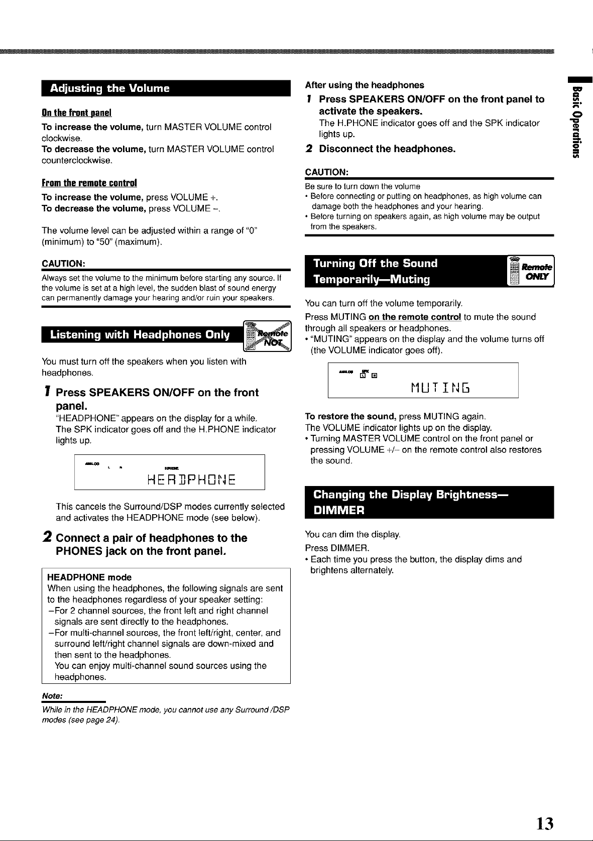
"HEADPHONE" appears on the display for a while.
The SPK indicator goes off and the H.PHONE indicator
lights up.
u
HE R,3PHI31qE
After using the headphones
1 Press SPEAKERS ON/OFF on the front panel to
activate the speakers.
The H.PHONE indicator goes off and the SPK indicator
lights up.
2 Disconnect the headphones.
CAUTION:
Be sure to turn down the volume
• Before connecting or putting on headphones, as high volume can
damage both the headphones and your hearing.
• Before turning on speakers again, as high volume may be output
from the speakers,
You can turn off the volume temporarily.
Press MUTING on the remote control to mute the sound
through all speakers or headphones.
• "MUTING" appears on the display and the volume turns off
(the VOLUME indicator goes off).
==, _,[]
I'IUT !NB
To restore the sound, press MUTING again.
The VOLUME indicator lights up on the display.
• Turning MASTER VOLUME control on the front panel or
pressing VOLUME +/- on the remote control also restores
the sound.
m
O
==
This cancels the Surround/DSP modes currently selected
and activates the HEADPHONE mode (see below).
2 Connect a pair of headphones to the
PHONES jack on the front panel.
HEADPHONE mode
When using the headphones, the following signals are sent
to the headphones regardless of your speaker setting:
-For 2 channel sources, the front left and right channel
signals are sent directly to the headphones.
-For multi-channel sources, the front left/right, center, and
surround left/right channel signals are down-mixed and
then sent to the headphones.
You can enjoy multi-channel sound sources using the
headphones.
Note:
While in the HEADPHONE mode, you cannot use any Surround/DSP
modes (see page 24).
You can dim the display.
Press DIMMER.
• Each time you press the button, the display dims and
brightens alternately.
]3
Page 16
Basic Operations
You can fall asleep while listening to music--Sleep Timer.
Basic adjustment auto memory
This receiver memorizes sound settings for each source
when--:
• you turn off the power,
• you change the source, and
• you assign the source name.
(Z) ._c_. #311
Q Q'Q_
'_ Q Q13
Q QvQ
®4 @U
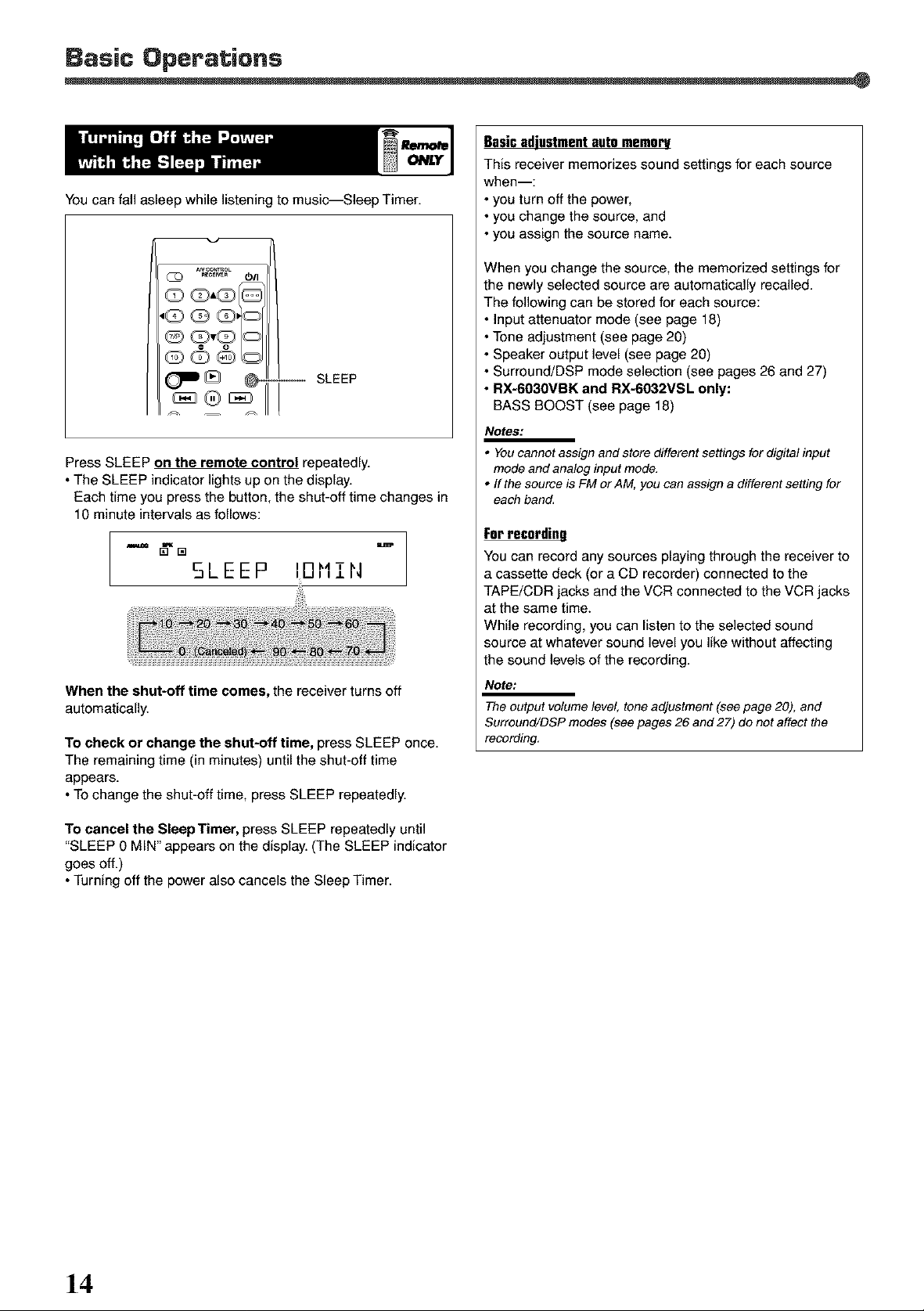
(J_J @ _ -- SLEEP
Press SLEEP on the remote control repeatedly.
• The SLEEP indicator lights up on the display.
Each time you press the button, the shut-off time changes in
10 minute intervals as follows:
SLEEP 101'111'4
When the shut-off time comes, the receiver turns off
automatically.
To check or change the shut-off time, press SLEEP once.
The remaining time (in minutes) until the shut-off time
appears.
• To change the shut-off time, press SLEEP repeatedly.
When you change the source, the memorized settings for
the newly selected source are automatically recalled.
The following can be stored for each source:
• Input attenuator mode (see page 18)
• Tone adjustment (see page 20)
• Speaker output level (see page 20)
• Surround/DSP mode selection (see pages 26 and 27)
• RX-6030VBK and RX-6032VSL only:
BASS BOOST (see page 18)
Notes:
• You cannot assign and store different settings for digital input
mode and analog input mode,
• ff the source is FM or AM, you can assign a different setting for
each band,
For recording
You can record any sources playing through the receiver to
a cassette deck (or a CD recorder) connected to the
TAPE/CDR jacks and the VCR connected to the VCR jacks
at the same time.
While recording, you can listen to the selected sound
source at whatever sound level you like without affecting
the sound levels of the recording.
Note:
The output volume level, tone adjustment (see page 20), and
Surround/DSP modes (see pages 26 and 27) do not affect the
recording,
To cancel the Sleep Timer, press SLEEP repeatedly until
"SLEEP 0 MIN" appears on the display. (The SLEEP indicator
goes off.)
• Turning off the power also cancels the Sleep Timer.
]4
Page 17
After connecting and placing speakers, you need to make
basic settings for the following items according to your
listening conditions.
• Speaker information (see the next column and page 16)
• Digital input terminal sources (see page 16)
• RX-6030VBK and RX-6032VSL only:
Video input terminal type (see page 16)
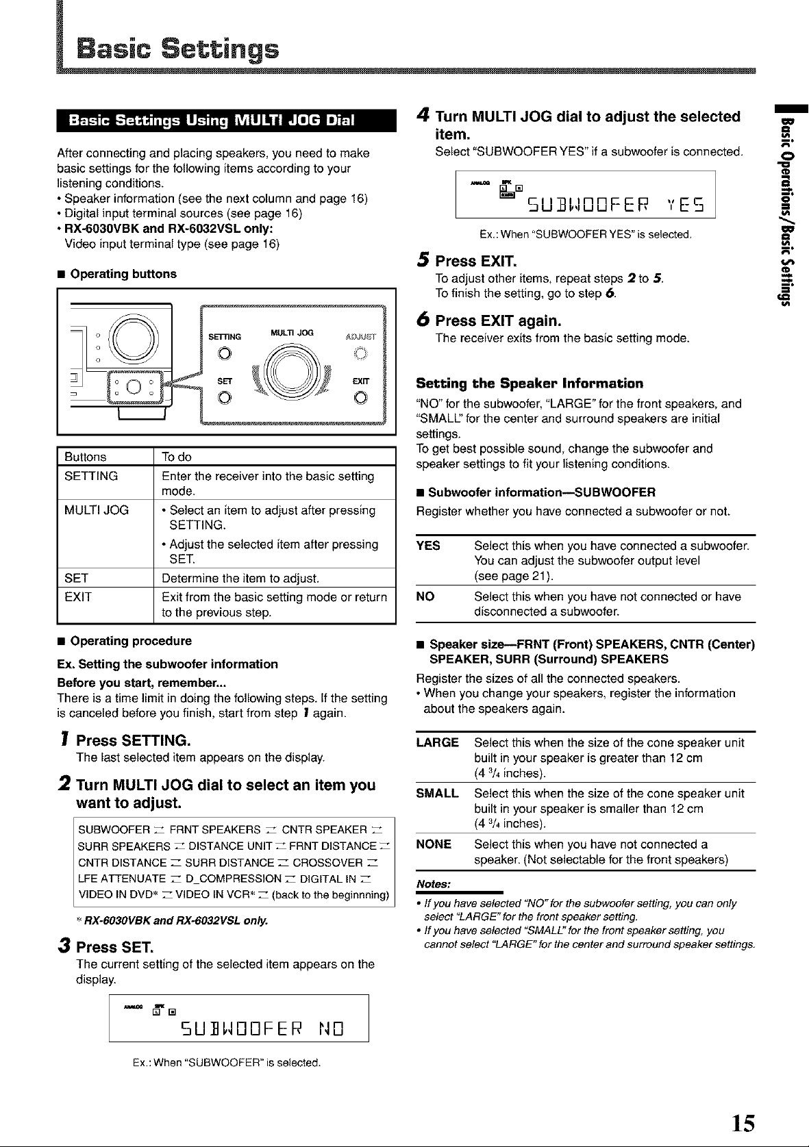
• Operating buttons
Buttons Todo
SETTING Enter the receiver into the basic setting
mode.
MULTI JOG • Select an item to adjust after pressing
SETTING.
• Adjust the selected item after pressing
SET.
SET Determine the item to adjust.
EXIT Exit from the basic setting mode or return
to the previous step.
4 Turn MULTI JOG dial to adjust the selected
item.
Select "SUBWOOFERYES" ifa subwoofer isconnected.
-= []SU]]H00FER YES
Ex.:When "SUBWOQFERYES" is selected.
Press EXIT.
Toadjust other items, repeatsteps 2 to 5.
Tofinish the setting, go to step 6.
6 Press EXIT again.
The receiver exitsfrom the basic setting mode.
Setting the Speaker Information
"NO" for the subwoofer, "LARGE" for the front speakers, and
"SMALL' for the center and surround speakers are initial
settings.
To get best possible sound, change the subwoofer and
speaker settings to fit your listening conditions.
• Subwoofer information--SUBWOOFER
Register whether you have connected a subwoofer or not.
YES Select this when you have connected a subwoofer.
You can adjust the subwoofer output level
(see page 21 ).
NO Select this when you have not connected or have
disconnected a subwoofer.
m
o
==
==
• Operating procedure
Ex. Setting the subwoofer information
Before you start, remember...
There is a time limit in doing the following steps. If the setting
is canceled before you finish, start from step ! again.
Press SETTING.
The last selected item appears on the display.
2 Turn MULTI JOG dial to select an item you
want to adjust.
SUBWOOFER _ FRNT SPEAKERS _ CNTR SPEAKER
SURR SPEAKERS _ DISTANCE UNITZ PRNT DISTANCE
CNTR DISTANCE _ SURR DISTANCE Z CROSSOVER
LFEATTENUATE Z D COMPRESSION Z DIGITALIN
VIDEO IN DVD* _ VIDEO IN VCR__ (back tothe beginnning)
RX-603OVBKand RX-6032VSL only.
3 Press SET.
The currentsetting oftheselected item appears on the
display.
-'= _'m
5U]]HOOFEP 1'40
• Speaker size--FRNT (Front) SPEAKERS, CNTR (Center)
SPEAKER, SURR (Surround) SPEAKERS
Register the sizes of all the connected speakers.
• When you change your speakers, register the information
about the speakers again.
LARGE Select this when the size of the cone speaker unit
built in your speaker is greater than 12 cm
(4 3/4inches).
SMALL Select this when the size of the cone speaker unit
built in your speaker is smaller than 12 cm
(4 3/4inches).
NONE Select this when you have not connected a
speaker. (Not selectable for the front speakers)
Notes:
• ffyou have selected "NO" for the subwoofer setting, you can only
select "LARGE" for the front speaker setting,
• ffyou have selected "SMALE' for the front speaker setting, you
cannot select "LARGE" for the center and surround speaker settings.
Ex.:When "SUBWOOFER"is selected.
]5
Page 18
Basic Settings
• Speaker distance---DISTANCE UNIT, FRNT DISTANCE,
CNTR DISTANCE, SURR DISTANCE
Select the unit to measure the distance between your listening
position and speakers--"METER" or "FEET."
After selecting the measuring unit, select the appropriate
speaker distance for each speaker within the range of "0.3m"
("1FT") to "9.0m" ("3OFT") by 0.3 m (1 foot) step.
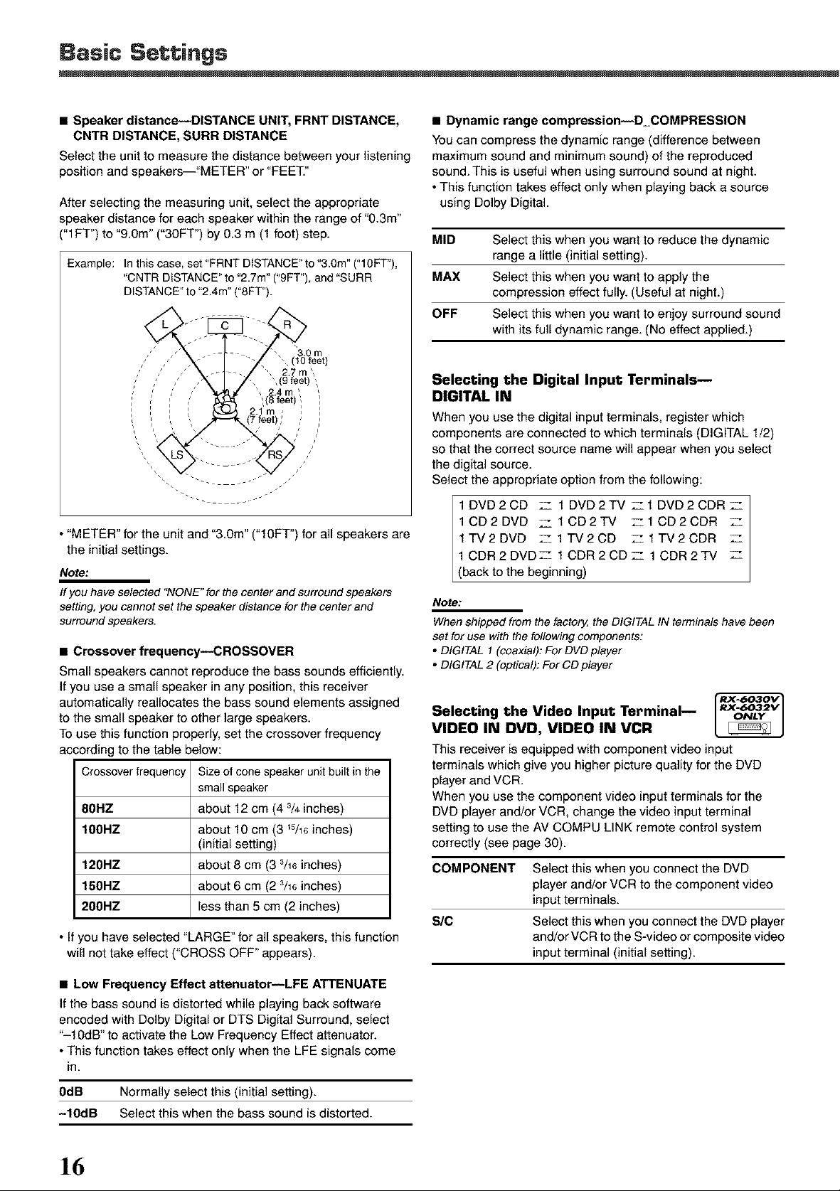
Example: Inthiscase, set"FRNTDISTANCE"te"3.0m"("lOFT"),
"CNTR DISTANCE" to "2.7m" ("9FT"), and "SURR
DISTANCE" to "2.4m" ("SFT").
• "METER" for the unit and "3.0m" ("lOFT") for all speakers are
the initial settings.
Note:
If you have selected "NONE" for the center and surround speakers
setting, you cannot set the speaker distance for the center and
surround speakers.
• Crossover frequency--CROSSOVER
Small speakers cannot reproduce the bass sounds efficiently.
Ifyou use a small speaker in any position, this receiver
automatically reallocates the bass sound elements assigned
to the small speaker to other large speakers.
To use this function properly, set the crossover frequency
according to the table below:
Crossoverfrequency Size of cone speaker unit built in the
small speaker
80HZ about 12 cm (4 % inches)
100RZ about 10 cm (3 _5/16inches)
(initial setting)
120RZ about 8 cm (3 3/16inches)
150RZ about 6 cm (2 3/16inches)
200HZ less than 5 cm (2 inches)
• If you have selected "LARGE" for all speakers, this function
will not take effect ("CROSS OFF" appears).
• Dynamic range compression--D_COMPRESSION
You can compress the dynamic range (difference between
maximum sound and minimum sound) of the reproduced
sound. This is useful when using surround sound at night.
• This function takes effect only when playing back a source
using Delby Digital.
MID Select this when you want to reduce the dynamic
range a little (initial setting).
MAX Select this when you want to apply the
compression effect fully. (Useful at night.)
OFF Select this when you want to enjoy surround sound
with its full dynamic range. (No effect applied.)
Selecting the Digital Input Terminals m
DIGITAL IN
When you use the digital input terminals, register which
components are connected to which terminals (DIGITAL 1/2)
so that the correct source name will appear when you select
the digital source.
Select the appropriate option from the following:
1DVD2CD Z 1DVD2TV Z1DVD2CDRZ
1CD2DVD Z 1CD2TV z1CD2CDR Z
1TV2DVD Z 1TV2CD Z1TV2CDR Z
1CDR2DVDZ 1CDR2CDZ 1CDR2TV Z
(back to the beg nn rig)
Note:
When shipped from the factory, the DIGITAL IN terminals have been
set for use with the following components:
• DIGITAL I (coaxial): For DVD player
• DIGITAL 2 (optical): For CD player
Selecting the Video Input Terminal--
RX..6032V
ONLY
VIDEO IN DVD, VIDEO IN VCR
This receiver is equipped with component video input
terminals which give you higher picture quality for the DVD
player and VCR.
When you use the component video input terminals for the
DVD player and/or VCR, change the video input terminal
setting to use the AV COMPU LINK remote control system
correctly (see page 30).
COMPONENT Select this when you connect the DVD
player and/or VCR to the component video
input terminals.
SIC Select this when you connect the DVD player
anoVorVCR to the S-video or composite video
input terminal (initial setting).
• Low Frequency Effect attenuator--LFE ATTENUATE
Ifthe bass sound is distorted while playing back software
encoded with Dolby Digital or DTS Digital Surround, select
"-10dB" to activate the Low Frequency Effect attenuator.
• This function takes effect only when the LFE signals come
in.
0dB Normally select this (initial setting).
-10dB Select this when the bass sound is distorted.
]6
Page 19
F_ Remotecontrol
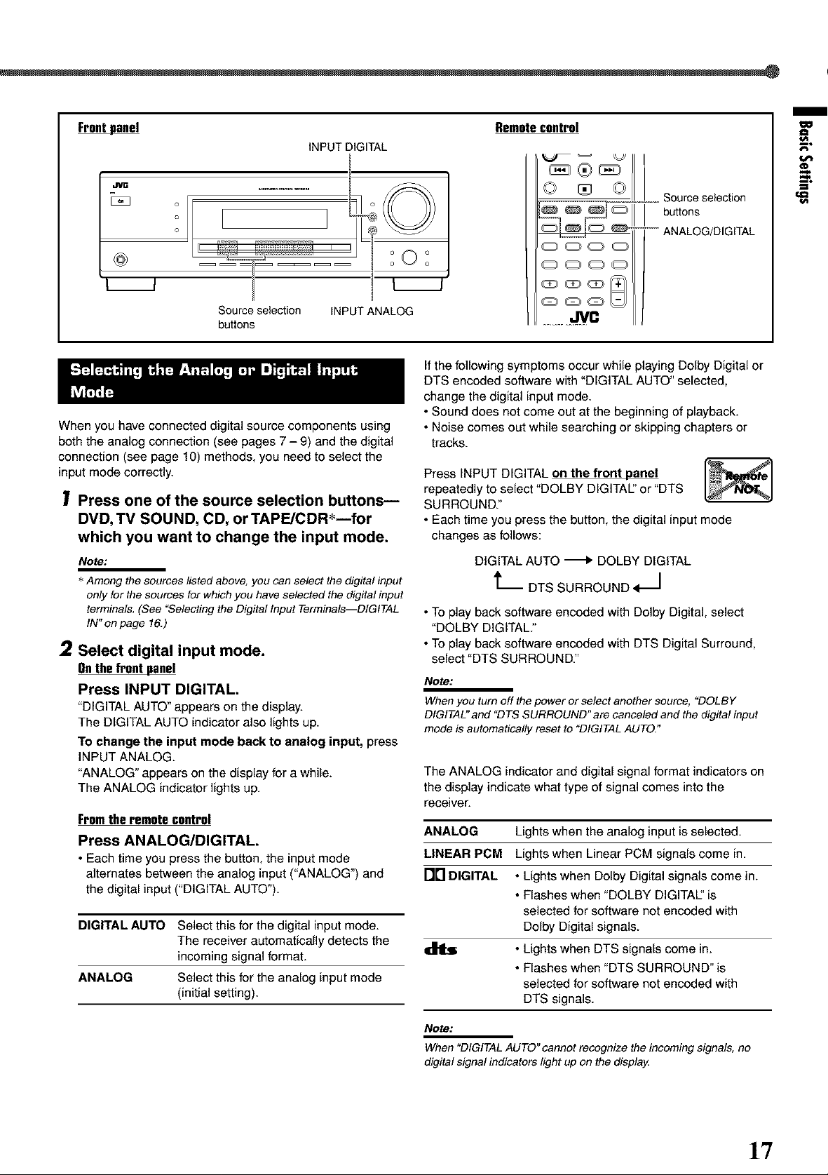
INPUT DIGITAL
Source selection INPUT ANALOG
buttons
Ifthe following symptoms occur while playing Dolby Digital or
DTS encoded software with "DIGITAL AUTO" selected,
change the digital input mode.
• Sound does not come out at the beginning of playback.
When you have connected digital sourcecomponents using
both the analog connection (see pages 7 - 9) and the digital
• Noise comes out while searching or skipping chapters or
tracks.
connection (see page10)methods, you need to select the
input mode correctly.
Press INPUT DIGITAL on the front panel I_l
Press one of the source selection buttons--
DVD, TV SOUND, CD, or TAPE/CDR*--for
which you want to change the input mode.
Note:
* Among the sources listed above, you can select the digital input
only for the sources for which you have selected the digital input
terminals, (See "Selecting the Digital Input Terminals--DIGITAL
IN" on page 16.)
2
Select digital input mode.
Onthefrontpanel
Press INPUT DIGITAL.
"DIGITALAUTO"appears on the display.
The DIGITALAUTO indicator also lights up.
repeatedly to select "DOLBY DIGITAL' or "DTS
SURROUND."
• Each time you press the button, the digital input mode
changes as follows:
DIGITAL AUTO _ DOLBY DIGITAL
t_ DTS SURROUND _1
• To play back software encoded with Dolby Digital, select
"DOLBY DIGITAL."
• To play back software encoded with DTS Digital Surround,
select "DTS SURROUND."
Note:
When you turn off the power or select another source, "DOLBY
DIGITAL" and "DTS SURROUND" are canceled and the digital input
mode is automatically reset to "DIGITAL AUTO."
TOchange the input mode back to analog input, press
INPUT ANALOG.
"ANALOG" appears on the display for a while.
The ANALOG indicatorlightsup.
The ANALOG indicator and digital signal format indicators on
the display indicate what type of signal comes into the
receiver.
Fromtheremotecontrol
Press ANALOG/DIGITAL.
• Each time youpress the button, the input mode
alternates between the analog input ("ANALOG")and
the digital input ("DIGITALAUTO").
DIGITAL AUTO Select this for the digital input mode.
The receiver automatically detects the
incoming signal format.
ANALOG Select this for the analog input mode
(initial setting).
ANALOG Lights when the analog input is selected.
LINEAR PCM Lights when Linear PCM signals come in.
Nrl DIGITAL • Lights when Dolby Digital signals come in.
• Flashes when "DOLBY DIGITAl" is
selected for software not encoded with
Dolby Digital signals.
• Lights when DTS signals come in.
• Flashes when "DTS SURROUND" is
selected for software not encoded with
DTS signals.
m
€€1
€€1
a
I/i
€I
Note:
When "DIGITAL AUTO"cannot recognize the incoming signals, no
digital signal indicators light up on the displa_
1"7
Page 20
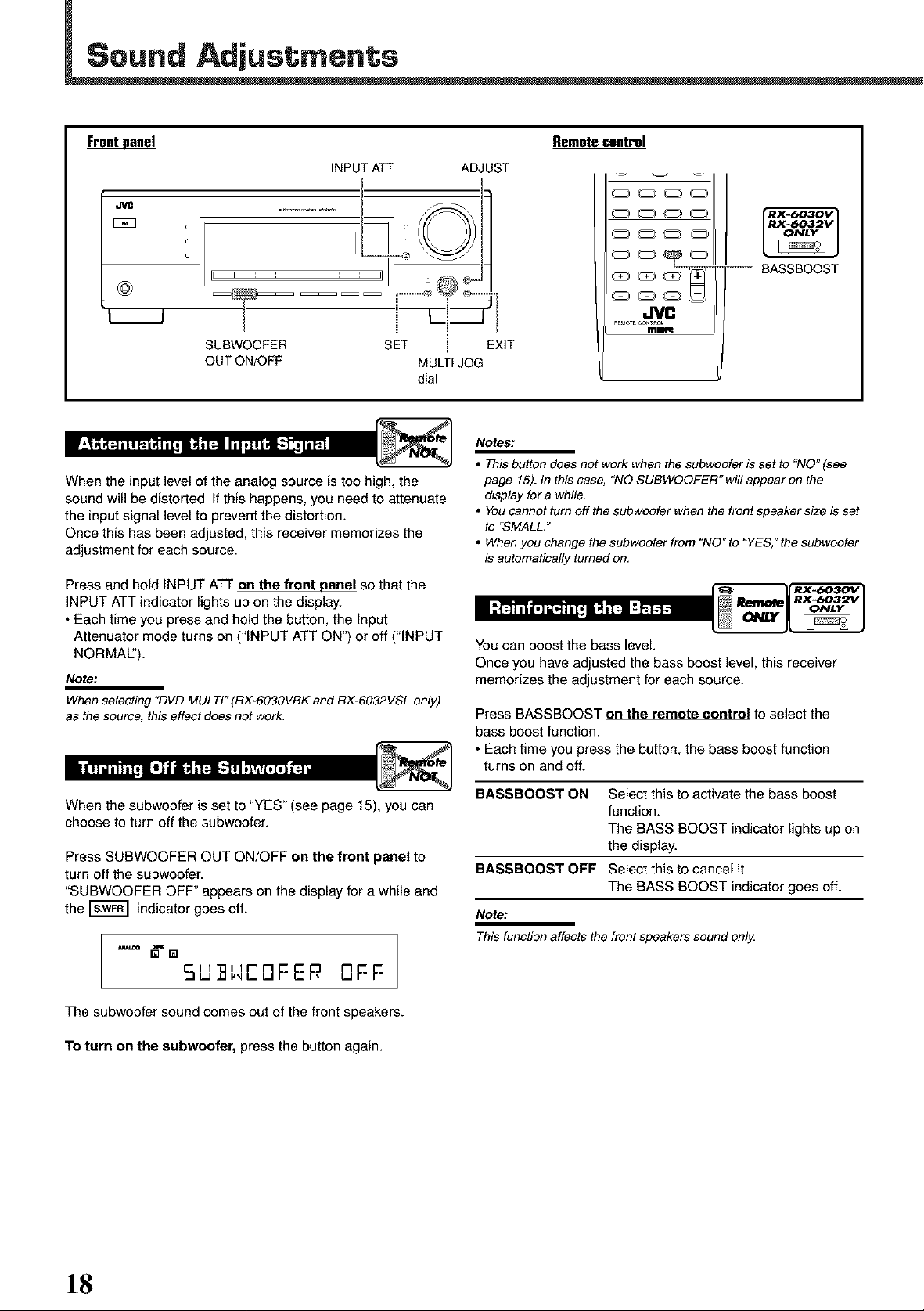
F_ Remotecontrol
INPUTATT ADJUST
.J_
o o
o
SUBWOOFER IT
OUT ON/OFF MULTIJOG
dial
When the input level of the analog source is too high, the
sound will be distorted. Ifthis happens, you need to attenuate
the input signal level to prevent the distortion.
Once this has been adjusted, this receiver memorizes the
adjustment for each source.
Press and hold INPUT ATT on the front panel so that the
INPUT ATT indicator lights up on the display.
• Each time you press and hold the button, the Input
Attenuator mode turns on ("INPUT ATT ON") or off ("INPUT
NORMAL').
Note:
When selecting "DVD MULTI" (RX-603OVBK and RX-6032VSL only)
as the source, this effect does not work,
ooo
ooo
BASSBOOST
dVC
aEMOTECONTaO_
m_
Notes:
• This button does not work when the subwoofer is set to "NO" (see
page 15). In this case, "NO SUBWOOFER" will appear on the
display for a while.
• You cannot turn off the subwoofer when the front speaker size is set
to "SMALL."
• When you change the subwoofer from "NO" to 'YES," the subwoofer
is automatically turned on,
I:t_Tt_l[q _ I:_tL'_,
You can boost the bass level.
Once you have adjusted the bass boost level, this receiver
memorizes the adjustment for each source.
Press BASSBOOST on the remote control to select the
bass boost function.
• Each time you press the button, the bass boost function
turns on and off.
When the subwoofer is set to "YES" (see page 15), you can
choose to turn off the subwoofer.
Press SUBWOOFER OUT ON/OFF on the front panel to
turn off the subwoofer.
"SUBWOOFER OFF" appears on the display for a while and
the _ indicator goes off.
5U I,4DDFER DFF
The subwoofer sound comes out of the front speakers.
To turn on the subwoofer, press the button again.
BASSBOOST ON Select this to activate the bass boost
function.
The BASS BOOST indicator lights up on
the display.
BASSBOOST OFF Select this to cancel it.
The BASS BOOST indicator goes off.
Note:
This function affects the front speakers sound only.
18
Page 21
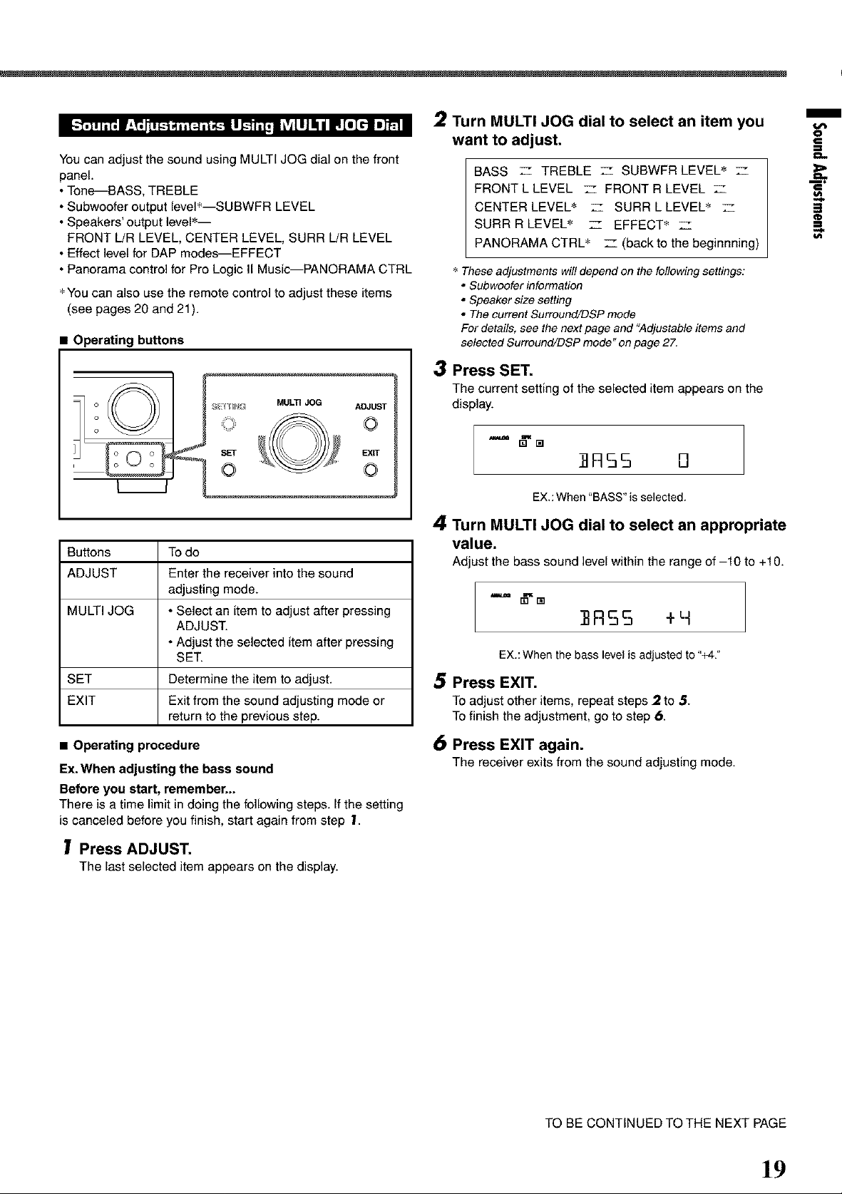
You can adjust the sound using MULTI JOG dial on the front
panel.
• Tone--BASS+ TREBLE
• Subwoofer output leveI_--SUBWFR LEVEL
• Speakers' output level +-
FRONT L!R LEVEL, CENTER LEVEL, SURR L!R LEVEL
• Effect level for DAP modes--EFFECT
• Panorama control for Pro Logic II Music--PANORAMA CTRL
+You can also use the remote control to adjust these items
(see pages 20 and 21).
• Operating buttons
Buttons Todo
ADJUST Enter the receiver into the sound
adjusting mode.
MULTI JOG • Select an item to adjust after pressing
ADJUST.
• Adjust the selected item after pressing
SET.
SET Determine the item to adjust.
EXIT Exit from the sound adjusting mode or
return to the previous step.
2 Turn MULTI JOG dial to select an item you
want to adjust.
BASS _- TREBLE _- SUBWFR LEVEL + z
FRONT L LEVEL z FRONT R LEVEL
CENTER LEVEL + __ SURR L LEVEL+
SURR R LEVEL_ _- EFFECT+ __
PANORAMA CTRL + _ (back to the beginnning)
+ These adjustments wil! depend on the following settings:
• Subwoefer information
• Speaker size setting
• The current Surround/DSP mode
For details, see the next page and "Adjustable items and
selected Surround/DSP mode" on page 27,
3 Press SET.
The current settingof the selected item appears on the
display.
]]FI55 B
EX,:When"BASS" is selected.
4 Turn MULTI JOG dial to select an appropriate
value.
Adjust the bass sound levelwithin the range of -10 to +10.
]]R55 +H
EX+:Whenthe bass level is adjustedto "+4:'
.5 Press EXIT.
Toadjustotheritems, repeatsteps 2 to 5.
Tofinish theadjustment,gotostep 6.
m
€
€1
_>=
€
3
¢D
€1
=,
• Operating procedure
Ex. When adjusting the bess sound
Before you start, remember...
There is a time limit in doing the following steps. If the setting
is canceled before you finish, start again from step 1.
Press ADJUST.
The lastselected item appears on thedisplay.
6 Press EXIT again.
The receiverexitsfromthe sound adjusting mode.
TO BE CONTINUED TO THE NEXT PAGE
]9
Page 22
• Tone--BASS,TREBLE
Adjust the bass and treble sounds as you like (-10 to +10 in 2
step intervals).
• "0" isthe initialsetting.
• Subwoofer output leveI--SUBWFR LEVEL
Adjust the subwoofer output level (-10 to +10 in 1 step
interval).
• "0" isthe initialsetting.
Note:
Subwoofer output level cannot be adjusted in the following cases:
• When "SUBWOOFER NO"is selected for the subwoofer setting (see
page 15).
• When the HEADPHONE mode is in use (see page 13).
• Speakers' output level
Adjust the speakers' output level so that you can hear sounds
from each speaker at an equal level (-10 to +10 in 1 step
interval).
• "0" isthe initialsetting for all speakers.
FRONT L LEVEL Left front speaker output level
FRONT R LEVEL Right front speaker output level
CENTER LEVEL_ Center speaker output level
SURR L LEVEL S Left surround speaker output level
SURR R LEVEL _ Right surround speaker output level
You can adjust these items depending on the current speaker
settings (see page 15) and Surreund/DSP mode (see "Adjustable
items and selected Surround/DSP mode" on page 27),
Notes:
• You cannot adjust the center speaker output level when the center
speaker size is set to "NONE" (see page 15),
• You cannot adjust the surround speaker output levels when the
surround speaker size is set to "NONE" (see page 15),
• Effect level for DAP modes--EFFECT
You can adjust the effect level for DAP modes only when one
of the DAP modes isactivated (EFFECT 1 to EFFECT 5).
"EFFECT 3" is the initial setting. As the number increases, the
effect becomes more stronger.
• For DAP modes, see page 25.
• Panorama control for Pro Logic II Music--
PANORAMA CTRL
You can turn on or off the Panorama control for Pro Logic II
Music only when "PL II MUSIC" is activated.
Select "PANORAMA ON" to enjoy "wraparound" sound effect
with side-wall image ("OFF" isthe initialsetting).
• For Pro Logic II Music, see page 24.
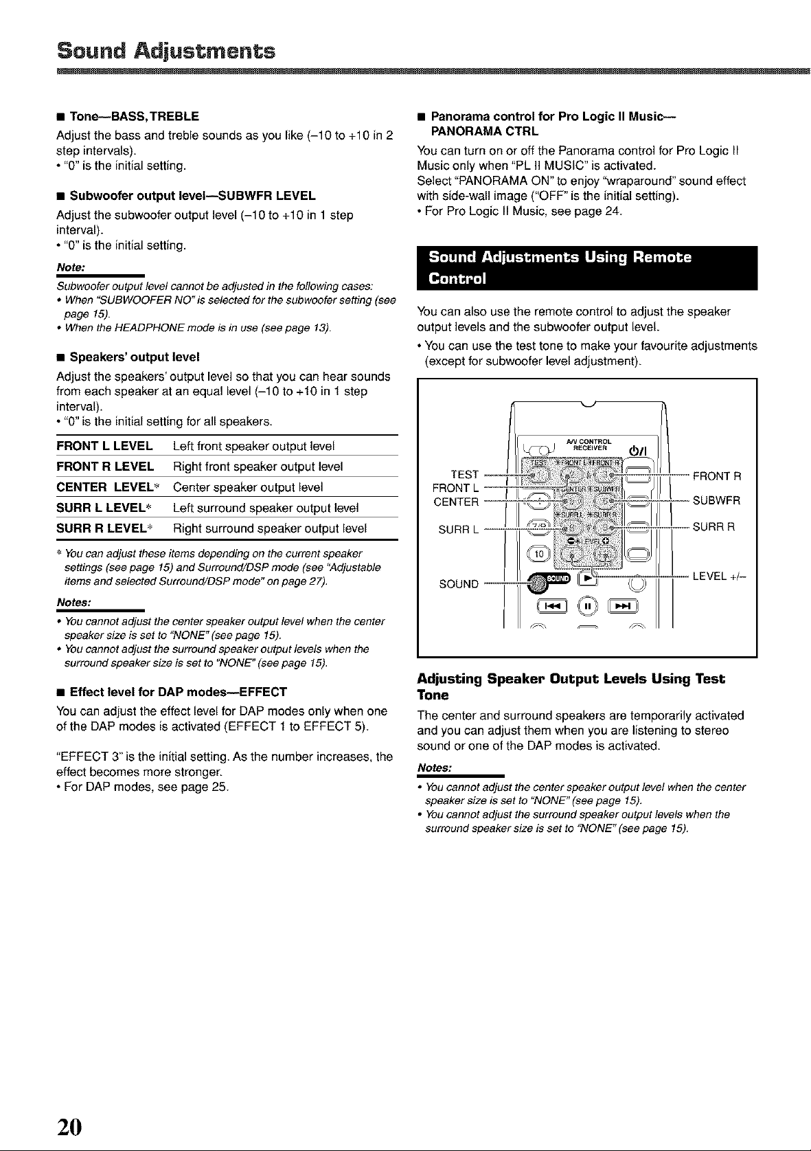
You can also use the remote control to adjust the speaker
output levels and the subwoofer output level.
• You can use the test tone to make your favoufite adjustments
(except for subwoofer level adjustment).
_VCONTROL
RECEWER 811
TEST FRONTR
FRONTL _HBWFR
CENTER _'._Js ;!!! _ _
SURR L _
Ill SURRR
SOUND _ _ LEVEL+/-
Adjusting Speaker Output Levels Using Test
Tone
The center and surround speakers are temporarily activated
and you can adjust them when you are listening to stereo
sound or one of the DAP modes is activated.
Notes:
• You cannot adjust the center speaker output level when the center
speaker size is set to "NONE" (see page 15),
• You cannot adjust the surround speaker output levels when the
surround speaker size is set to "NONE" (see page 15),
2O
Page 23
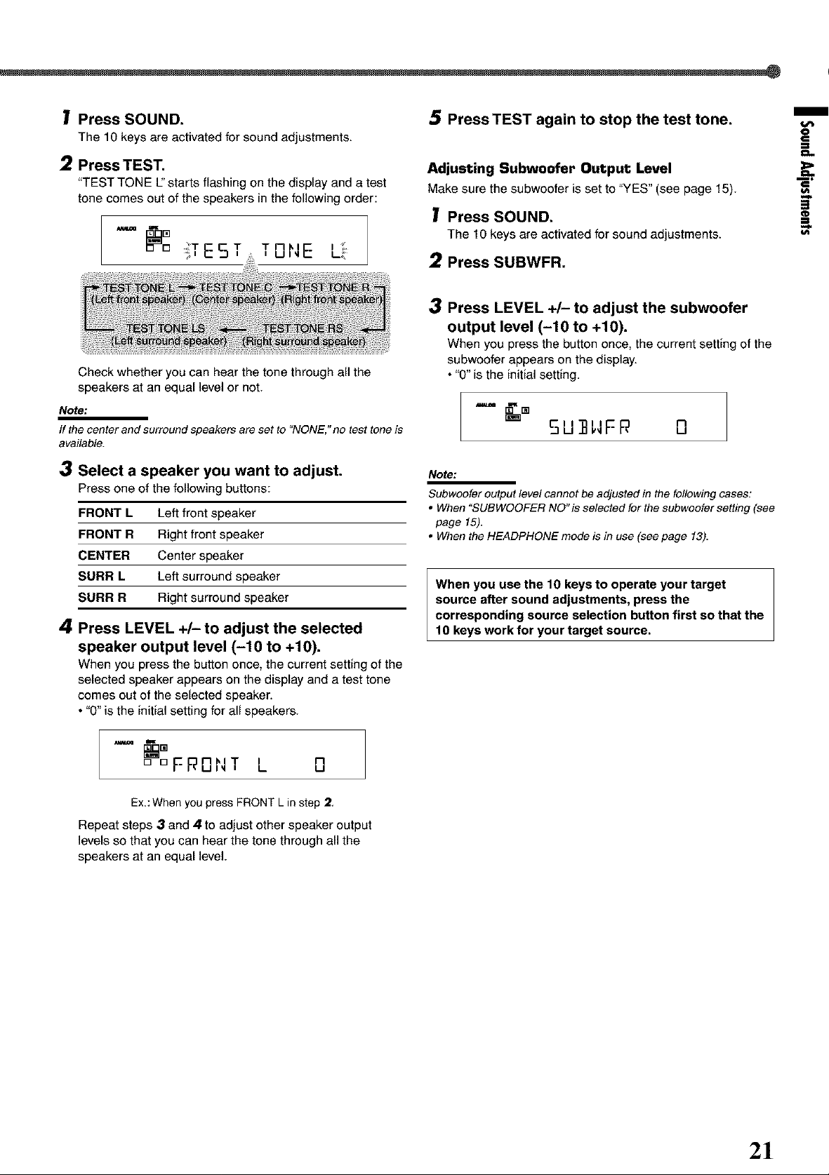
I Press SOUND.
The 10 keysare activated for sound adjustments.
2 Press TEST.
"TESTTONE U'starts flashing on the display and a test
tone comes out of the speakers in the following order:
iTE5T TONE ,._
Check whether you can hear the tone through all the
speakers at an equal level or not.
Note:
if the center and surround speakers are set to "NONE," no test tone is
available.
Press TEST again to stop the test tone.
Adjusting Subwoofer Output Level
Make surethe subwoofer is set to "YES"(see page 15).
I Press SOUND.
The 10keysareactivatedfor sound adjustments.
Press SUBWFR.
3 Press LEVEL +/- to adjust the subwoofer
output level (-10 to +10).
When you press the button once, the current setting of the
subwoofer appears on the display.
• "0" is the initial setting.
"= _'m
5U ]]"F P, O
m
O
€
=3
€
=3
3 Select a speaker you want to adjust.
Press one of the following buttons:
FRONT L Left front speaker
FRONT R Right front speaker
CENTER Center speaker
SURR L Left surround speaker
SURR R Right surround speaker
4
Press LEVEL +/-to adjust the selected
speaker output level (-10 to +10).
When you press the button once, the current setting of the
selected speaker appears on the display and a test tone
comes out of the selected speaker.
• "0" is the initial setting for all speakers.
,,-=. am
[] D F F_UI_I i I
Ex.:When you press FRONT Lin step 2.
Repeat steps 3 and 4 to adjust other speaker output
levels so that you can hear the tone through all the
speakers at an equal level.
nhlT n
L- U
Note:
Subwoofer output level cannot be adjusted in the following cases:
• When "SUBWOOFER NO"is selected far the subwoofersetting (see
page 15).
• When the HEADPHONE mode is in use (see page 13).
When you use the 10 keys to operate your target
source after sound adjustments, press the
corresponding source selection button first so that the
10 keys work for your target source.
2!
Page 24
F_ Remotecontrol
10 keys ----
V
(Z 3 "_c_" Oii
iiil
_®_
FM/AM FM/AM FM MODE
TUNING PRESET
A/V A/V
i iTI_TI_j hil [_ I-._ hV_Ftl"_!lfflI_vj
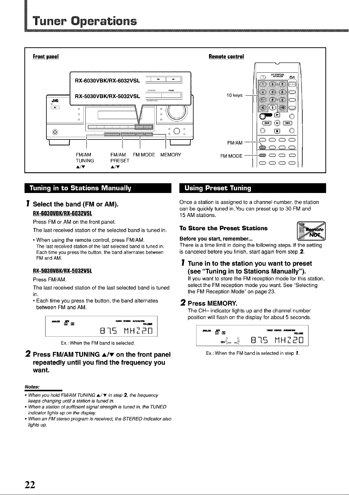
I Select the band (FM or AM).
RX-6030VBI(/RX-6032VSL
Press FMor AM onthe front panel.
The last received station of the selected band is tuned in.
• When using the remote control, press FM/AM.
The last received station of the last selected band is tuned in.
Each time you press the button, the band alternates between
FM and AM.
RX-5030VBI(/RX-5032VSL
Press FM/AM.
The last received station of the last selected band is tuned
in.
• Each time you press the button, the band alternates
between FM and AM.
•--= _,[] "-= '=_ "=_...
B7.5 MHZ20
MEMORY
FM/AM --
FM MODE --
Once a station is assigned to a channel number, the station
can be quickly tuned in.You can preset up to 30 FM and
15 AM stations.
To Store the Preset Stations I_l
Before you start, remember...
There is a time limit in doing the following steps. If the setting
is canceled before you finish, start again from step 2.
ooo
@ooo
oooo
I Tune in to the station you want to preset
(see "Tuning in to Stations Manually").
If you want to store the FM reception mode for thisstation,
select the FM reception mode you want. See "Selecting
the FM Reception Mode" on page 23.
2 Press MEMORY.
The CH- indicator lights up andthe channel number
position will flash on the display for about 5 seconds.
Ex.:When the FMbandisselected.
2 Press FM/AM TUNING A/v on the front panel
repeatedly until you find the frequency you
want.
Notes:
• When you hold FM/AM TUNING A/T in step 2, the frequency
keeps changing until a station is tuned in,
• When a station of sufficient signal strength is tuned in, the TUNED
indicator lights up on the display
• When an FM stereo program is received, the STEREO indicator also
lights up.
22
875 "" "20
Ex.:When the FM band is selected in step f.
Page 25
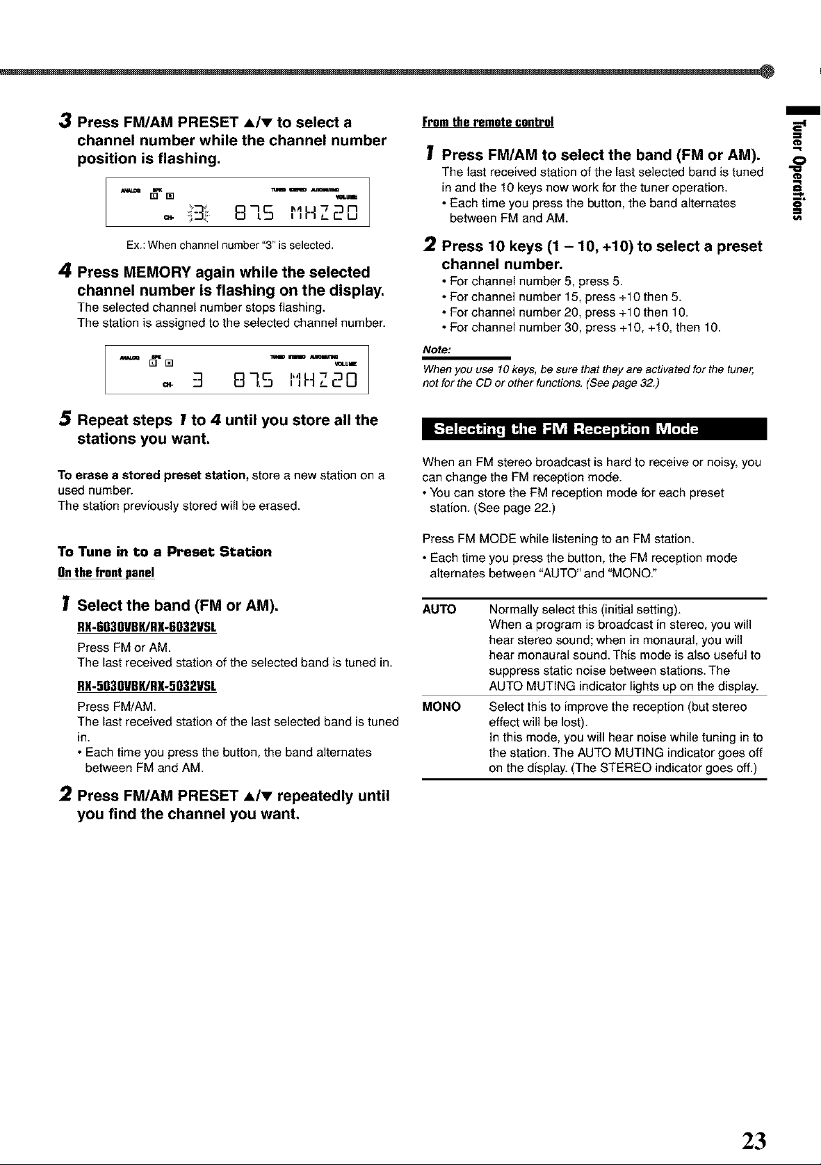
3 Press FM/AM PRESET A/v to select a
channel number while the channel number
position is flashing.
. ,_: 8]5 I'IHZ20
Fromthe remote control
1 Press FM/AM to select the band (FM or AM).
The last received station of the last selected band is tuned
in and the 10 keys now work for the tuner operation.
• Each time you press the button, the band alternates
between FM and AM.
m
O
¢D
5"
t/i
Ex.:When channel number '*3"is selected.
4 Press MEMORY again while the selected
channel number is flashing on the display.
The selected channel numberstopsflashing.
The station is assigned to the selected channel number.
"3 m-],.5 I'IH 720
Repeat steps 1 to 4 until you store all the
stations you want.
To erase a stored preset station, store a new station on a
used number.
The station previously stored will be erased.
To Tune in to a Preset Station
Onthefrontpanel
1
Select the band (FM or AM).
RX-603OVBK/RX-6032VSL
Press FMor AM.
The last received station of the selected band is tuned in.
RX-503OVBK/RX-5032VSL
Press FM/AM
The last received station of the last selected band is tuned
in.
• Each time you press the button, the band alternates
between FM and AM.
2 Press 10 keys (1 - 10, +10) to select a preset
channel number.
•For channel number 5, press 5.
• Forchannel number 15, press +10 then 5.
• Forchannel number 20, press +10 then 10.
• Forchannel number 30, press +10, +10, then 10.
Note:
When you use 10 keys, be sure that they are activated for the tuner,
not for the CD or other functions, (See page 32.)
l---_J_r4 _ I;l_r_lI::F_F4'_:'l'_t_l _'Jl'_,_
When an FM stereo broadcast is hard to receive or noisy, you
can change the FM reception mode.
• You can store the FM reception mode for each preset
station. (See page 22.)
Press FM MODE while listening to an FM station.
• Each time you press the button, the FM reception mode
alternates between "AUTO" and "MONO:'
AUTO
MONO
Normally select this (initial setting).
When a program is broadcast in stereo, you will
hear stereo sound; when in monaural, you will
hear monaural sound. This mode is also useful to
suppress static noise between stations. The
AUTO MUTING indicator lights up on the display.
Select this to improve the reception (but stereo
effect will be lost).
In this mode, you will hear noise while tuning in to
the station. The AUTO MUTING indicator goes off
on the display. (The STEREO indicator goes off.)
2
Press FM/AM PRESET A/v repeatedly until
you find the channel you want.
23
Page 26
You can use the following Surround and DSP modes to
reproduce a realistic sound field:
Surl"ound•odes
• Doiby
• Dolby Pro Logic II
• Dolby Digital
• DTS Digital Surround
DSP•odes
• DAP modes
• All Channel Stereo
Surround•odes
• DoII_j
Dolby Pro Logic II_
Dolby Pro Logic II has a multi-channel playback format to
decode all 2 channel sources--stereo source and Doiby
Surround encoded source--into 5.1 channels.
Matrix-based encoding/decoding method for Dolby Pro Logic II
makes no limitation for the cutoff frequency of the rear treble
and enables stereo rear sound compared to conventional Dolby
Pro Logic.
Do]by Pro Logic IIenables reproduction of spacious sound
from original sound without adding any new sounds and tonal
colorations.
Doiby Pro Logic II has two modes--Movie mode and Music
mode:
Pro Logic II Movie (PL II MOVIE) suitable for the
reproduction of Dolby Surround encoded sources bearing the
mark nr_[DoL._s...o_._3.You can enjoy a sound field very close to
the one created with discrete 5.1 channel sounds.
Pro Logic II Music (PL II MUSIC) suitable for the
reproduction of any 2 channel stereo music sources.You can
enjoy wide and deep sound by using this mode. For this mode,
Panorama control can be selected, which gives "wraparound"
sound effect with side-wall image.
• When Doiby Pro Logic II is activated, the D['I PRO LOGIC II
indicator lights up on the display.
Dolby Digital 5.1 channel encoding method (so-called
discrete multi-channel digital audio format) records and
digitally compresses the left front channel, right front channel,
center channel, left surround channel, right surround channel,
and LFE channel signals.
Since each channel is completely independent from the other
channel signals to avoid interference, you can obtain much
better sound quality with many stereo and surround effects.
• When Dolby Digital signal comes in, the DEI DIGITAL
indicator lights up on the display.
Note:
Dolby Digital software can roughly be grouped into two categories
--multi-channel (up to 5.1 channel) and 2 channel software. To enjoy
surround sounds while playing Dolby Digital 2 channel software, you
can use Delby Pro Logic I1.
• DTS Digital Surround _
Used to reproduce multi-channel sound tracks of software
encoded with DTS Digital Surround (_).
• To use software encoded with DTS Digital Surround, connect
the source component to the digital terminal on the rear of
this receiver. (See page 10.)
DTS Digital Surround is another discrete multi-channel
digital audio format available on CD, LD, and DVD software.
Compared to Dolby Digital, the audio compression ratio is
relatively low. This fact allows DTS Digital Surround format to
add breadth and depth to the reproduced sounds. As a result,
DTS Digital Surround features natural, solid, and clear sound.
• When DTS signal comes in, the _ indicator lights up on
the display.
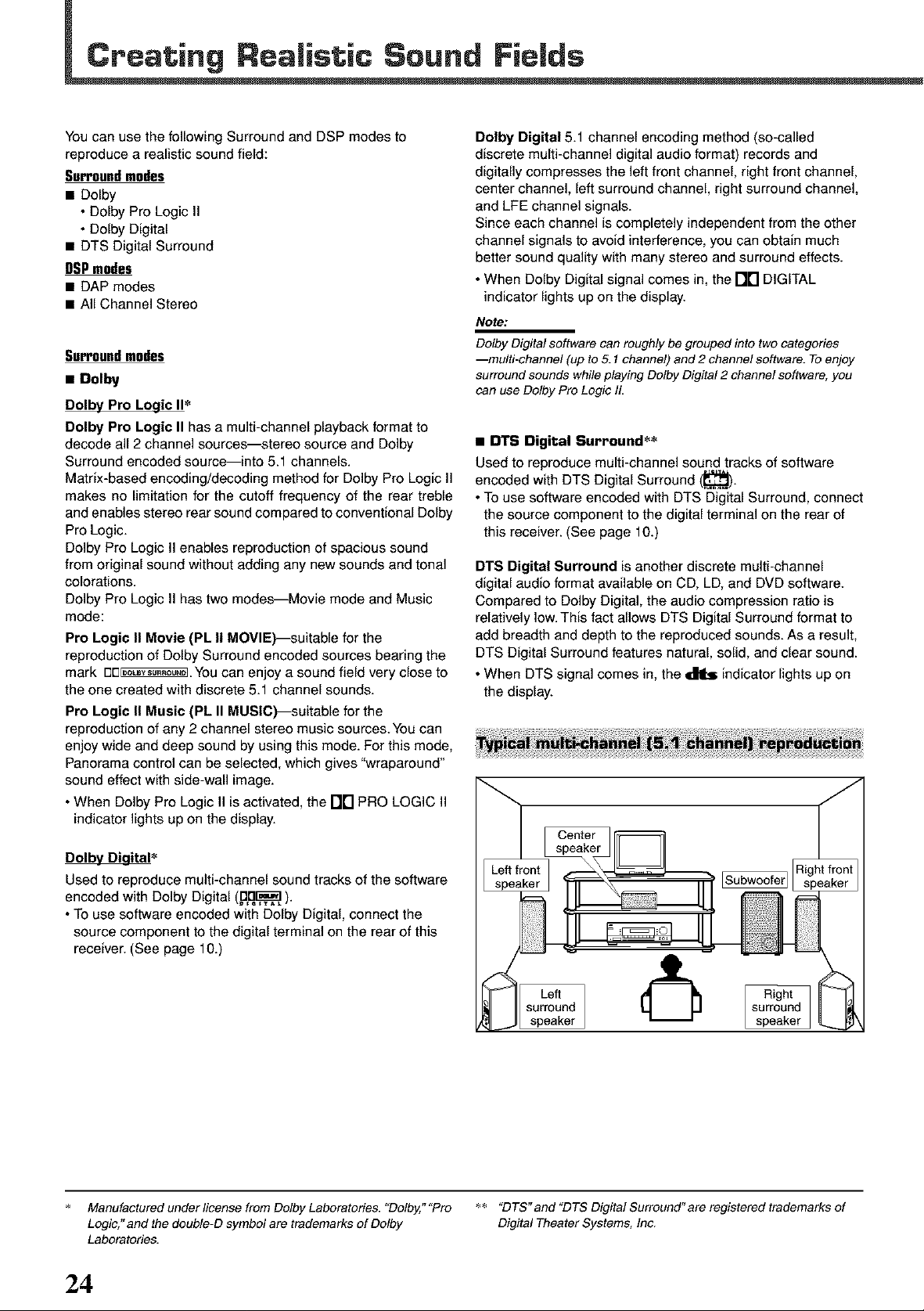
Center
speaker
Used to reproduce multi-channel sound tracks of the software
encoded with Dolby Digital (_D._. _).
• To use software encoded with Dolby Digital, connect the
source component to the digital terminal on the rear of this
receiver. (See page 10.)
Manufactured under license from Dolby Laboratories. "Dolby," "Pro _ "DTS" and "DTS Digital Surround" are registered trademarks of
Logic," and the double-D symbol are trademarks of Dolby Digital Theater Systems, Inc.
Laboratories.
24
Page 27

DSP•odes
• DAP (Digital Acoustic Processor) modes
DAP modes have been designed to create important acoustic
surround elements.
The sound heard in a live club, dance club, hall or pavilion
consists of direct sound and indirect sound---early reflections
and reflections from behind. Direct sounds reach the listener
directly without any reflection. On the other hand, indirect
sounds are delayed by the distances of the ceiling and walls
(see the diagram on the right).
These indirect sounds are important elements of the acoustic
surround effects. The DAP mode can reproduce a realistic
sound field by adding these indirect sounds.
DAP modes can be used when the front and surround
speakers are connected to this receiver (without respect
to the center speaker connection: no sound comes out of
the center speaker even if it is connected).
The following DAP modes are provided with this receiver:
LIVE CLUB Gives the feeling of a live music club with a
low ceiling.
DANCE CLUB Gives a throbbing bass beat.
HALL Gives clear vocal and the feeling of a concert
hall.
PAVILION Gives the spacious feeling of a pavilion with a
high ceiling.
These DAP modes can be used to add the acoustic surround
effects while reproducing 2 channel stereo software--either
analog or digital except Dolby Digital and DTS Digital
Surround--and can give you a real "being there" feeling.
• When one of the DAP modes is selected, the DSP indicator
lights up on the display.
Early
Reflectionsfrom behind _ - J f
Direct sounds
• All Channel Stereo
This mode can reproduce a larger stereo sound field using all
the connected (and activated) speakers.
All Channel Stereo can be used when the front and
surround speakers are connected to this receiver without
respect to the center speaker connection.
Ifthe center speaker is connected and activated, the same
phase of the front left and right signals is emitted through the
center speaker.
All Channel Stereo can be used while reproducing 2 channel
stereo software, either analog or digital except Dolby Digital
and DTS.
• When All Channel Stereo is selected, the DSP indicator
lights up on the display.
m
0
Q.
_D
4>
Normal stereo reproduction Sound reproduced from
Available Surround/DSP modes for each input signal ©: Available x : Not available
s SURROUND DOLBY DTS PL II PL II LIVE DANCE HALL PAVILION ALL OH
OFF (stereo) DIGITAL SURROUND MOVIE MUSIC CLUB CLUB STEREO
Dolby Digital
(Multi-channel O O x x x x x x x x
Dolby Digital
(2 channel) O x x O © x x x x x
DTS Digital
Surround O x O x x x x x x x
(Multi-channel)
DTS Digital
Surround O x x O © x x x x x
(2 channel)
Linear PCM O x x O © O O © O ©
Analog O x x O © O O © O ©
All Channel Stereo
25
Page 28

Creating Realistic Sound Fields
F_ Remotecontrol
DSP SURROUND
--DSP
E i II
t________!
SURROUND/DSP OFF
Speaker layouts required for Surround modes are as follows:
• 5 channels
(Front, center, and surround speakers
are connected.)
• 4 channels
(Front and surround speakers are
connected.)
• 3 channels
(Front and center speakers are
connected.)
= Operating procedure
Select the source you want to listen to and
start playing.
• Whenplayingbacksoftware encodedwithDolby Digital
and DTS DigitalSurround, selectthe digital input mode
(see page 17).
SURROUND
oooo
-----SURROUND/DSP
OFF
2 Press SURROUND,
The appropriate Surround mode will be activated
according to the incoming signal.
• DOLBY DIGITAL:
Activated if you are playing back multi-channel
software encoded with Dolby Digital.
• DTS SURROUND:
Activated if you are playing back software encoded
with DTS Digital Surround.
• PL II MUSIC • or PL II MOVIE:
Activated if you are playing back any software other
than the above. (The last one selected will be
activated.)
The NR PRO LOGIC II indicator lights up on the
display.
Press SURROUND repeatedly to select the one
appropriate for the source.
When "PL fl MUSIC"is selected, you can select Panorama control
to enjoy 'Wraparound'sound effect with side-wal!image (see
page 19for the settingprocedure).
Notes:
• When "DOLBY DIGITAL"or "DTS SURROUND'is selected with
no surround speakers connected, the surround sounds are
downmixed and output from the front speakers.
• For the available Surround modes according to the input signals,
see "Available Surround/DSP modes for each input signal" on
page 25.
To adjust the speaker output level and select Panorama
control for Pro Logic II Music, see pages 19 to 21.
The adjustment is memorized for each source (except for
Panorama control).
26
To turn off Surround mode, press SURROUND/DSP OFE
Page 29

Speaker layouts required for the DSP modes are as follows:
• 5 channels
(Front, center, and surround speakers
are connected.)
• 4 channels
(Front and surround speakers are
connected.)
• Operating procedure
1 Start playing 2 channel softwarHither
analog or Linear PCM--and select the
source.
2 Press DSP.
The last selected DSP mode will be activated and the DSP
indicator lights up on the display.
• Each time you press the button, the DSP mode changes
as follows:
L,VEO'UBOANOEOLUO.ALL
L ALLCHSTEREO4-_PAVILIONJ
(AllChannel Stereo)
Note:
For the availableDSP modes according to inputsignals, see
"AvailableSurround/DSP modes foreach input signal" onpage
25.
To adjust the speaker output level and the effect level for
DAP mode, see pages 19 to 21.
The adjustment is memorized for each source (except for the
effect level).
• Adjustable items and selected Surround/DSP mode
• For adjustment operation, see pages 19 to 21. -_
Selected Surround/ Adjustable items Adjustable ==
DSP mode range
DOLBY DIGITAL, FRONT L LEVEL -10 to +10 =_
DTS SURROUND, FRONT R LEVEL =L,
PL II MOVIE CENTER LEVEL _'_
SURR L LEVEL o,
SURR R LEVEL
SUBWFR LEVEL
LIVE CLUB,
DANCE CLUB,
HALL
PAVILION
FRONT L LEVEL
FRONT R LEVEL
SURR L LEVEL
SURR R LEVEL
SUBWFR LEVEL
EFFECT
-10 to +10
1 to5
m
==
(A ste ;
Notes:
• Regardless of the selected Surround/DSP mode,
- You cannot adjust the center speaker output level when the center
speaker size is set to "NONE" (see page 15).
- You cannot adjust the surround speaker output levels when the
surround speaker size is set to "NONE" (see page 15).
• You cannot adjust the subwoofer output level when "SUBWOOFER
NO"is selected far the subwoofer setting (see page 15).
_..-=
0
To turn off DSP mode, press SURROUND/DSP OFE
Signal and speaker indicators on the displal/
Signal indicators Speaker indicators
The following signal indicators light up--:
L: • When digital input is selected: Lights up when the
left channel signal comes in.
• When analog input is selected: Always lights up.
R: • When digital input is selected: Lights up when the
right channel signal comes in.
• When analog input is selected: Always lights up.
C: When the center channel signal comes in.
LS: When the left surround channel signal comes in.
RS: When the right surround channel signal comes in.
S: When the monaural surround channel signal comes in.
LFE: When the LFE channel signal comes in.
The speaker indicators light up when the corresponding
speaker is connected and activated.
Notes:
• When "SUBWOOFER YES"is selected for the subwoofer setting
(see page 15) and the subwoofer is turned on (see page 18),
lights up.
• When you select "DVD MULTI"(RX-603OVBK and RX-6032VSL
only), all the signal indicators except "S" light up.
27
Page 30

This section is ONLY for RX-6030VBK and RX-6032VSL
Fromthe remote control
This receiver provides the DVD MULTI playback mode for
reproducing the analog discrete output mode of the DVD
player. Before playing a DVD, refer also to the manual supplied
with the DVD player.
r_'_j I,]VA,] I_,_LtJkllI-..,lI_"_)_,'_J_ _'_l'_':_
Onthefrontpanel
oooE,1O!oo
DVD MULTI
%J
(Z) _c_ O/I
Q Q,Q_
®
@G?@_
_®_
-- DVD MULTI
0000
Press DVD MULTI.
- u.
Note:
When you select "DVD MULTI" as the source to play, Surround/
DSP mode is canceled, and SURROUND and DSP buttons do
not work.
I1L'II I'IULTI 32
Press DVD MULTI.
_'_ I'IULTi 32
Note:
When you select "DVD MULTI" as the source to play, Surround/
DSP mode is canceled, and SURROUND and DSP buttons do
not work,
2 Select the analog discrete output mode on
the DVD player, and start playing a DVD.
• Referalsoto the manual supplied withthe DVD player.
If you want to adjust the sound, see pages 19 to 21.
Once you have made adjustments, the receiver retains the
adjustments until you change them.
2 Select the analog discrete output mode on
the DVD player, and start playing a DVD.
• Referalso to the manual supplied withthe DVDplayer.
If you want to adjust the sound, see pages 19 to 21.
Once you have made adjustments, the receiver retains the
adjustments until you change them.
28
Page 31

The COMPU LINK remote control system allows you to
operate JVC's audio components through the remote sensor
on the receiver.
To use this remote control system, you need to connect JVC's
audio components through the COMPU LINK-4 (SYNCHRO)
jacks (see below) in addition to the connections using cables
with RCA pin plugs (see page 7).
• Make sure that the AC power cords of these components are
unplugged before connection. Plug in the AC power cords
only after all other connections are completed.
Cassette deck CD player
AutomaticSourceSelection
When you press the play (_) button on a connected
component or on its own remote control, the receiver
automatically turns on and changes the source to the
component. On the other hand, if you select a new source on
the receiver or on the remote control, the selected component
begins playing immediately.
In both cases, the previously selected source continues
playing without sound for a few seconds.
AutomaticPowerOn/Off(Standby):onlypossiblewith the
COMPULINK-3andCOMPULINK-4
Both the CD player and cassette deck (or CD recorder) turn
on and off (standby) along with the receiver.
When you turn on the receiver, the CD player or cassette deck
(or CD recorder) will turn on automatically, depending on
which component has been previously selected.
When you turn off the receiver, both the CD player and
cassette deck (or CD recorder) will turn off (standby).
SynchronizedRecording
Synchronized recording means the cassette deck starts
recording as soon as a CD begins playing.
To use synchronized recording, follow these steps:
Put a tape in the cassette deck and a disc in
the CD player.
i
€€1
c
"o
i
ft_
3€
8.
0
3€
"o
-5
v/J
3
Notes:
• There are four versions of the COMPU LINK remote control system.
This receiver is equipped with the fourth version_OMPU LINK-4.
This version adds systematic operations with the CD recorder to the
previous version_OMPU LINK-3.
• If your audio component has two COMPU LINK jacks, you can use
either one. If it has only one COMPU LINK jack, connect it so that it
is the last item in the series of components,
• To operate the cassette deck or CD recorder using the COMPU
LINK remote control system, set the source name correctl_z
(See page 12.)
• Refer also to the manuals supplied with your audio components.
This remote control system allows you to use the four
functions listed below.
Remote Control through the Remote Sensor on the Receiver
You can control the connected audio components through the
remote sensor on the receiver using this remote control. Aim
the remote control directly at the remote sensor on the
receiver. For details, see pages 32 and 33.
2 Press the record (o) button and the pause
(11) button on the cassette deck at the same
time.
This putsthe cassette deck into recording pause.
Ifyoudonot pressthe record (o) button and pause (11)
button at the same time, the synchronized recording
feature will notoperate.
3
Press the play (_) button on the CD player.
The source changes on the receiver, and as soon as play
starts, the cassette deck starts recording. When the play
ends, the cassette deck enters recording pause, and stops
about 4 seconds later.
No_s:
• During synchronized recording, the selected source cannot be
changed.
• ff the power of any component is shut off during synchronized
recording, the COMPU LINK remote control system may not operate
properly In this case, you must start again from the beginning.
29
Page 32

The AV COMPU LINK remote control system allows you to operate JVC's video components (TV, VCR, and DVD player) through
the receiver.
To use this remote control system, you need to connect the video components you want to operate following the diagrams below
and the procedure on the next page.
RX-6030VBKiRX-6032VSL
This receiver is equipped with the AV COMPU LINK-IlL which added a function to operate JVC's video components through the
component video terminals.
• AV COMPU LINK Connection
Rear pane
..........ovo0,a e
TV
Notes:
• YOUcan connect to the TV with the AV COMPU LINK III or AV COMPU LINK EX terminal
A TV with AV COMPU LINK RECEIVER!AMP terminal can net be used.
• When connecting the receiver and a TV with the AV COMPU LINK EX terminal by using a component video cable, you cannot use the
Automatic Selection of TV's Input Mode (see page 31).
• Video cable connection
• When connecting the DVD player and/or the VCR to the receiver using the composite video terminals, also connect this
receiver to the TV's Video Input 2 terminals (composite video input) using composite video cables.
• When connecting the DVD player and/or the VCR to the receiver using the S-video terminals, also connect this receiver to
the TV's Video Input 1 terminals (S-video input) using S-video cables.
• When connecting the DVD player and/or the VCR to the receiver using the component video terminals, also connect this
receiver to the TV's Video Input 2 terminals (component video input) using component video cables.
To use the AV COMPU LINK remote control system, set the video input terminal type for the DVD player and theVCR
correctly (see "Selecting the Video Input Terminal--VIDEO IN DVD, VIDEO IN VCR" on page 16),
RX-5030VBI(/RX-5032VSL
• AV COMPU LINK connection
i l eel _ _} Rear panel
TV
II -Jl IL "" JJ [
Note:
Youcanconnect to the TV with theAV COMPU LINK EX orAV COMPULINK III terminal.
A TV with AV COMPU LINKRECEIVER/AMP terminal can not be used.
• Video cable connection
Connect the DVD player and/or the VCR to this receiver using the VIDEO (composite video) terminals, and connect this
receiver to the TV's Video Input 2 terminals (composite video input) using composite video cables
3O
Page 33

Notes: One-TouchDVDPlay
• When connecting only the VCR or DVD player to this receiver,
connect it directly to the receiver using cables with the monaural
mini-plugs.
• Make sure that the remote control code of the VCR connected to the
VCR jacks is set to code "A."
• Refer also to the manuals supplied with your video components,
m Connecting procedure
!
If you have already plugged your VCR, DVD player,
TV and this receiver into the AC outlets, unplug their
AC power cords first.
2
Connect your VCR, DVD player, TV and this receiver
Simply by starting playback on the DVD player, you can view
the DVD playback without setting other switches manually.
• When the DVD player is connected through the analog input
jacks on this receiver (and analog input is selected), the
receiver automatically turns on and changes the source to
"DVD" (or "DVD MULTI"_RX-6030VBK and RX-6032VSL
only).
• When the DVD player is connected through the digital input
terminal on this receiver (and digital input is selected), the
receiver automatically turns on and changes the source to
"DVD DIGITAL."
• The TV automatically turns on and changes the input mode
to the appropriate position so that you can view the
playback.
as illustrated on page 30, using the cables with
monaural mini-plugs (not supplied).
Automatic Selection of the Ti/Input Mode
3
Connect the audio/video input/output jacks on VCR,
DVD player, TV and this receiver (see pages 8 and
9).
4
Plug the AC power cords of the components into the
AC outlets.
5
When turning on the TV for the first time after the AV
COMPU LINK connection, turn the TV volume to the
minimum using the TV volume control on the TV.
6
Turn on the other connected components first, then
turn on this receiver.
• When turning on the VCR, use the remote control
supplied with this receiver (press STANDBY/ON (b/I
VCR).
The AV COMPU LINK remote control system allows you to
use the five basic functions listed below.
RemoteControloftheTV,DVDplayer,andVCRusingthis
RemoteControl
See page 34 for details.
• Aim the remote control directly at the remote sensor on
each target component.
One-TouchVideo Play
Simply by inserting a video cassette without its safety tab into
the VCR, you can start video playback without setting other
switches manually. The receiver automatically turns on and
changes the source to "VCR:'
The TV automatically turns on and changes the input mode to
the position so that you can view the playback.
When you insert a video cassette with its safety tab, press the
play (_) button on the VCR or on the remote control to get the
same result.
• When you select "TV SOUND" as the source to play on the
receiver, the TV automatically changes the input mode to the
TV tuner so that you can watch TV.
• When you select "DVD"or "VCR" (or "DVD MULTI"_
RX-6030VBK and RX-6032VSL only) as the source to play
on the receiver, the TV automatically changes the input
mode to the appropriate position so that you can view the
playback.
Note for RX-603OVBK and RX-6032VSL:
When connecting a TV with the AV COMPU LINK EX terminal to this
receiver, you cannot use a component video cable. Connect the TV
using an S-video or composite video cable.
AutomaticPowerOn/Off
The TV, VCR, and DVD player turn on and off along with the
receiver.
When you turn on the receiver;
• If the previously selected source is "VCR," the TV and VCR
will turn on automatically.
• If the previously selected source is "TV SOUND," only the TV
will turn on automatically.
• If the previously selected source is "DVD" (or "DVD MULTI"--
RX-6030VBK and RX-6032VSL only), the TV and DVD
player will turn on automatically.
When you turn off the receiver, the TV, VCR, and DVD player
will turn off.
Note:
If you turn off the receiver while recording on the VCR, the VCR will
not turn off, but continue recording.
I
O
3
pc
=
=
3!
Page 34

You can use the remote control to operate other JVC
components.
llF_,tr ./t"a tTzrnzm
IM PORTANT:
To operate JVC's audio components using this remote control:
• You need to connect JVC's audio components through the COMPU
LINK-4 (SYNCHRO) jacks (see page 29) in addition to the
connections using cables with RCA pin plugs (see page 7).
• Aim the remote control directly at the remote sensor on the receiver.
• If you use the buttons on the front panel, the remote control will not
operate that source. To operate a source with the remote control, the
source must be selected using source selection buttons on the
remote control.
• To operate the cassette deck or CD recorder using the COMPU
LINK remote control system, set the source name correctly. (See
page 12.)
• Refer also to the manuals supplied with your audio components.
SoundAdiustment
You can always use the following buttons:
SURROUND Turn on and select the Surround
modes.
DSP Turn on and select the DSP modes.
SURROUND/DSP OFF Turn off the Surround or DSP
modes.
After pressing SOUND, you can use the following buttons for
the sound adjustment:
SUBWFR -* LEVEL +/- Adjust the subwoofer output level.
FRONT L -* LEVEL +/- Adjust the left front speaker
output level.
FRONT R -* LEVEL +/- Adjust the right front speaker
output level.
CENTER -* LEVEL+l- Adjust the center speaker output
level.
SURR L -* LEVEL+l- Adjust the left surround speaker
output level.
SURR R -* LEVEL+l- Adjust the right surround speaker
output level.
TEST Turn on or off the test tone
output.
JVC JVC
Note:
When you use the 10 keys to operate your target source after sound
adjustments, press the corresponding source selection button first so
that the 10 keys work for your target source.
Tuner
You can always use the following buttons:
FM/AM Alternate between FM and AM.
After pressing FM/AM, you can use the following buttons for
the tuner operations:
1 - 10, +10 Select a preset channel number directly.
• For channel number 5, press 5.
• For channel number 15, press +10_ then 5.
• For channel number 20, press +10_ then 10.
FM MODE Change the FM reception mode.
32
Page 35

After pressing CD, you can use the following buttons for the
CD operations:
Cassette deck
After pressing TAPE/CDR, you can use the following buttons
for the cassette deck operations:
m
0
Start playback.
1<41 Return to the beginning of the current
(or previous) tracks.
Skip to the beginning of the next tracks.
• Stop playback.
II Pause playback. To release, press _.
1- 10, +10 Select a track number directly.
• For track number 5, press 5.
• For track number 15, press +10, then 5.
• For track number 20, press +10, then 10.
CDchanger
After pressing CD-DISC, you can use the following buttons for
the CD changer operations:
Start playback.
1<41 Return to the beginning of the current
(or previous) tracks.
Skip to the beginning of the next tracks.
• Stop playback.
II Pause playback. To release, press _.
1- 6, 7/P Select the number of a disc installed in a CD
changer.
After pressing CD, you can use the following buttons for the
CD changer operations:
1- 10, +10 Select a track number directly.
• For track number 5, press 5.
• For track number 15, press +10, then 5.
• For track number 20, press +10, then 10.
• For track number 30, press +10, +10, then 10.
Example:
Selecting disc number 4, track number 12, and starting
playback.
1 Press CD-DISC, then press 4.
2 Press CD, then press +10, 2.
Start playback.
FF Fast wind a tape from left to right.
REW Fast wind a tape from right to left.
• Stop playback or recording.
II Pause playback. To release, press D,-.
REC PAUSE Press this button to enter recording pause.
Press this button then D,-to start recording.
Note:
Beforestarting the above operations, make sure thatyouhave
changed the source name correctly.See page 12.
CDrecorder
After pressing TAPE/CDR, you can use the following buttons
for the CD recorder operations:
Start playback.
_1 Return to the beginning of the current
(or previous) tracks.
Skip to the beginning of the next tracks.
• Stop playback.
II Pause playback. To release, press D,-.
REC PAUSE Press this button to enter recording pause.
Press this button then D,-to start recording.
Note:
Beforestarting the above operations, make sure thatyouhave
changed the source name correctly.See page 12.
€
8
3
"8
If your CD changer is of 200-disc loading capability
(except for XL-MC100 and XL-MC301),
you can do the following operations using the number buttons
after pressing CD:
1 Select a disc number.
2 Select a track number (always enter two digits).
3 Start playback.
Examples:
• Selecting disc number 3, track number 2, and starting
playback.
Press 3, then, 0, 2, then D,-.
• Selecting disc number 10, track number 5, and starting
playback.
Press 1,0, then, O,5, then _.
• Selecting disc number 105, track number 12, and starting
playback.
Press 1,0, 5, then 1,2, then _.
33
Page 36

Operating JVC's Audio/Video Components
VCR
You can always use the following buttons:
IM PORTANT:
To operate JVC's video components using this remote control:
• You need to connect JVC's video components through the AV
DOMPU LiNK terminals (see page 30) in addition to the connections
using cables with RDA pin ptugs (see pages B end 9).
• Some JVC VCRs can accept two types of contrel signals--remote
code "A" and "B." Before using this remote control, make sure that
the remote control code of the VCR connected to the VCR jacks is
set to code "A."
• When using the remote control, aim the remote contret directly at
the remote sensor on each component, not on the receiven
STANDBY/ON (b/I VCR Turn on or off a VCR.
VCR OR +/- Change the TV channels on the
After pressing VCR, you can use the following buttons for the
VCR operations:
FF Fast wind a tape.
REW Rewind a tape.
• Stop playback or recording.
II Pause playback. To release, press _.
1 - 9, 0 Select aTV channel on the VCR.
REC PAUSE Press this button to enter recording pause.
VCR.
Start playback.
Press this button then _ to start recording.
fV
You can always use the following buttons:
STANDBY/ON O/I TV/CATV
Turn on or off a TV.
TV/VlDEO Change the input mode (TV tuner and
video input).
TV VOLUME +/- Adjust the volume.
TV/CATV CR +/- Change the channels.
You can always use the following buttons:
STANDBY/ON (b/I DVD Turn on or off a DVD player.
After pressing DVD (or DVD MULTI*) of the source selection
buttons, you can use the following buttons for the DVD
operations:
Start playback.
Return to the beginning of the current
(or previous) chapters.
Skip to the beginning of the next chapters.
• Stop playback.
II Pause playback. To release, press _.
RX-603OVBKand RX-6032VSL only.
DVD menu operations
After pressing DVD (or DVD MULTI*), you
can use the following buttons for DVD
menu operations:
_i _ __#_i_ _i £_B_ ;_
MENU _ S_JF_ i _ £_ _
RX-603OVBKand RX-6032VSL only.
u 4
MENU Display or hide the menu screen.
A/v/l,,_/_l Select an item on the menu screen.
ENTER (10) Enter a selected item.
After pressing TV SOUND, you can use the following buttons
for the TV and CATV operations:
1- 9, 0, +10 (100+) Select a channel.
RETURN (10) Function as the RETURN button.
34
Page 37

By changing the transmission signals, you can use the remote
control supplied for this unit to operate other manufacturers'
equipment.
• Refer also to the manuals supplied for the other products.
• To operate these components with the remote control, first
you need to set the manufacturers' code each for TV, CATV
converter, VCR and DVD player.
• When replacing the batteries in the remote control, set the
manufacturers' codes again.
To change the transmission signals for
operating a TV
! Set TV/CATV selector to "TV."
2 Press and hold STANDBY/ON O/I TV/CATV.
3 PressTV SOUND.
4 Enter manufacturer's codes using buttons
1 - 9, and O.
5 Release STANDBY/ON _/i TV/CATV.
Now,youcan perform the following operations on theTV.
STANDBY/ON dJ/ITV/CATV
Turnonor off the TV.
TV/VIDEO Set the input mode (either TV or
VIDEO).
TV VOLUME +/- Adjust the volume.
TV/CATV OH+/- Change the channels.
After pressing TV SOUND, you can perform the following
operations on the TV:
1 - 9, 0, +10 (100+) Select a channel
ENTER (10) Function as the ENTER button.
Note:
Referalso to the manual supplied with your TV
6 Try to operate yourTV by pressing
STANDBY/ON _/I TV/CATV.
When your TV turns on or off, you have entered the correct
codes.
If more than one code is listed for your brand of TV, try
each one until the correct one is entered.
Manufacturers' codes for TV
Manufacturer
JVC
Hitachi
Magnavox
Mitsubishi
Panasonic
RCA
Samsung
Sanyo
Sharp
Sony
Toshiba
Zenith
"01"is the initial settin
Codes
01_
10
O2
O3
04, 11
O5
12
13
O6
07
O8
O9
To change the transmission signals for
operating a CAW converter
! SetTV/CATV selector to "CATV."
2 Press and hold STANDBY/ON (b/iTV/CATV.
3 PressTV SOUND.
4 Enter manufacturer's codes using buttons
1 - 9, and 0.
5 Release STANDBY/ON O/i TV/CATV.
Now,youcan perform the following operations onthe
CATVconverter.
STANDBY/ON (b/ITV/CATV
Turn on or off the CATVconverter.
TV/CATV CH+/- Change thechannels.
After pressing TV SOUND, you can perform the following
operations on the CATV converter:
1 - 9, 0, +10 (100+) Select the channels.
ENTER (10) Function as the ENTER button.
Note:
Refer also to the manual supplied with your CATV converter.
6
Try to operate your CATV converter by
pressing STANDBY/ON _/I TV/CATV.
When yourCATVconverter turnson or off, you have
entered the correct codes.
If more than one code is listed for your brand of CATV
converter, try each one until the correct one is entered.
Manufacturers' codes for CATV converter
Manufacturer Codes
Echostar 01
General Instrument 02, 03, 04, 05,
06, 07, 08, 09
Hamlin 16, 17, 18, 19
Pioneer 14, 15
RCA 20
Scient 10, 11
Sony 21
Zenith 12, 13
* "01"is the initial setting.
Manufacturers' codes are subject to change
without notice, If they are changed, this remote
control cannot operate the equipment.
m
O
2-
¢1
€=1
O
E
-g
¢1
¢1
O
¢1
o
€1
¢1
€€
.=-
O
€€
-5"
3
=_
35
Page 38

To change the transmission signals for
operating a VCR
! Press and hold STANDBY/ON ®/i VCR.
2 Press VCR.
3 Enter manufacturer's codes using buttons
1 - 9, and O.
4 Release STANDBY/ON O/i VCR.
Now,youcan perform the following operations on the
VCR.
STANDBY/ON _)/IVCR Turn on oroff the VCR.
VCR OH+/- Change the channels.
After pressing VCR, you can perform the following
operations on the VCR:
Start playback.
FF Fastwind a tape.
REW Rewind a tape.
• Stop playback or recording.
II Pause playback. To release, press _.
REC PAUSE Press this button to enter recording
pause.
Then press D,-to start recording.
Note:
Referalso to the manual supplied with your VCR.
5 Try to operate your VCR by pressing
STANDBY/ON _o/iVCR.
When your VCR turns on or off, you have entered the
correct codes.
If more than one code is listed for your brand of VCR,
try each one until the correct one is entered.
Manufacturers' codes for VCR
Manufacturer Codes
JVC 01 _, 02, 03
Emerson 10, 22
Gold Star 11
Hitachi 04
Mitsubishi 12
NEC 21
Panasonic 07, 13
Philips 09
RCA 05, 06
Samsung 20
Sanyo 17, 18, 19
Sony 14, 15, 16
Zenith 08
"01"is the initial settin
To change the transmission signals for
operating a DVD player
! Press and hold STANDBY/ON (b/i DVD.
2 Press DVD.
3 Enter manufacturer's codes using buttons
1 - 9, and O.
4 Release STANDBY/ON O/i DVD.
Now,youcan usethe following buttons on the DVD player.
D,- Start playback.
• Stop playback.
Skip to the beginning of the next chapters.
Return to the beginning of the current (or previous)
chapters.
II Pause playback.To release,press_.
DVD menu operations
After pressing DVD (or DVD MULTI_),
you can use the following buttons for
DVD menu operations:
RX-603OVBKand RX-6032VSL only.
MENU Display or hide the menu screen.
&/v/_/_l Select an item on the menu screen.
ENTER (10) Enter a selected item.
,@ Q,
MENkl b SJ_ _, _ 2
O
ENTER _" _V {)
4
5 Try to operate your DVD player by pressing
STANDBY/ON _o/iDVD.
When your DVDplayer turns on or off, you have entered
the correctcodes.
Manufacturers' codes for DVD player
Manufacturer Codes
JVC 01_
Panasenic 02
Philips 04
Pioneer 03
Sony 05
Toshiba 06
Yamaha 07
"01"is the initial setting.
Manufacturers' codes are subject to change
without notice. If they are changed, this remote
control cannot operate the equipment.
+I l?
36
Page 39

Use this chart to help you solve daily operational problems. If there is any problem you cannot solve, contact your JVC service
center.
m
PROBLEM
The power does not come on.
No sound from speakers.
Sounds from speakers are heard The speaker output level is not set
unequally, correctly.
No test tone is available. The speakers are deactivated.
Continuous hiss or buzzing during FM Incoming signal is too weak.
reception.
Occasional cracking noise during FM Ignition noise from automobiles. Move the antenna farther from automobile
reception, traffic.
"OVERLOAD" starts flashing on the
display.
"DSP MICOM NG" starts flashing on The built-in microcomputer is not Press STANDBY/ON dOllon the front panel to
the display, functioning correctly, turn off the receiver. After unplugging the
The STANDBY lamp lights up after The receiver is overloaded because of a Press STANDBY/ON dO/Ion the front panel to
turning on the power, but soon the high voltage, turn off the receiver. After unplugging the
receiver turns off (into standby mode), power cord, consult your dealer.
Remote control does not work. There is an obstruction in front of the Remove the obstruction.
Remote control does not operate as The remote control is not ready for your Press SOUND or source selection buttons first,
you intend, intended operation, then press the button you want to use.
The powercord is not plugged in.
Speaker signal cables are not
connected.
An incorrect source is selected.
Muting is activated.
An incorrect input mode (analog or
digital) is selected.
Connections are incorrect.
Speaker signal cables are not connected
properly.
The station is too far away.
The wrong antenna is being used.
Antennas are not connected properly. Check connections.
Speakers are overloaded because of
high volume.
Speakers are overloaded because of
short circuit of speaker terminals.
remote sensor on the receiver.
Batteries are weak. Replace batteries in the remote control.
POSSIBLE CAUSE
SOLUTION
Plug the power cord into an AC outlet.
Check speaker wiring and reconnect if
necessary.
Select the correct source.
Press MUTING on the remote control to cancel
the mute.
Select the correct input mode (analog or
digital).
Check connections.
For analog connections, see pages 7 - 9.
For digital connections, see page 10.
Check speaker wiringand reconnect if
necessary.
Adjust the speaker output level (see pages 19
-21).
Press SPEAKERS ON/OFF on the front panel
to activate the speakers (see page 13).
Connect an outdoor FM antenna or contact
your dealer.
Select a new station.
Check with your dealer to be sure you have the
correct antenna.
1. Press STANDBY/ON dOllon the front panel
to turn oft the receiver.
2. Stop the playback source.
3. Turn on the receiver again, and adjust the
volume.
Press STANDBY/ON dOllon the front panel,
then check the speaker wiring.
If "OVERLOAD" does notdisappear after
turning on the receiver again, unplug the AC
power cord, then plug it back in again.
If speaker wiring is not short-circuited, contact
your dealer.
power cord, consult your dealer.
(See pages 32 - 36).
==
O
5
37
Page 40

RX-6030VBK/R_6032VSL
Amplifier
Audio
Audio Input Sensitivity/Impedance (1 kHz):
Audio Input (DIGITAL IN)x:
Audio Output Level:
Signal-to-Noise Ratio ('66 [HF/'78 [HF):
Frequency Response (8 _2):
Video
Video Input Sensitivity/Impedance:
Composite video:
Component video:
Video Output Level/Impedance:
Composite video:
Component video:
Signal-to-Noise Ratio:
Output Power:
Bass boost:
Tone Control:
S-video:
S-video:
Synchronization:
At Stereo operation:
Front channels: 100 W per channel, rain. RMS, driven into 8 £, 40 Hz to
At Surround operation:
Front channels: 100 W per channel, min. RMS, driven into 8 _ at 1 kHz with no
Center channel: 100 W, min. RMS, driven into 8 _ at 1 kHz, with no more than
Surround channels: 100 W per channel, min. RMS, driven into 8 _ at 1 kHz, with no
CD, TAPE/CDR, VCR, TV SOUND, DVD: 220 mV/47 k£_
Coaxial: DIGITAL 1 (DVD): 0.5 V (p-p)/75 £_
Optical: DIGITAL 2 (CD): -21 dBm to -15 dBm (660 nm -+30 nm)
Corresponding to Linear PCM, Dolby Digital, and DTS Digital Surround
(with sampling frequency--32 kHz, 44.1 kHz, 48 kHz).
TAPE/CDR, VCR: 220 mV
CD, TAPE/CDR, VCR, TV SOUND, DVD: 87 dB/78 dB
CD, TAPE/CDR, VCR, TV SOUND, DVD: 20 Hz to 20 kHz (-+1dB)
Bass (100 Hz): -+10dB
Treble (10 kHz): -+10dB
DVD, VCR: 1 V(p-p)/75
DVD, VCR: (Y: luminance): 1 V(p-p)/75
DVD, VCR: (Y: luminance): 1 V(p-p)/75
VCR, MONITOR OUT:
VCR, MONITOR OUT: (Y:luminance):
MONITOR OUT: (Y: luminance):
Negative
45 dB
20 kHz with no more than 0.8% total harmonic
distortion.
more than 0.8% totat harmonic distortion.
0.8% total harmonic distortion.
more than 0.8% total harmonic distortion.
+3 dB _+1dB at 100 Hz
(C:chrominance, burst): 0.286 V(p-p)/75_2
(Ps, PR): 0.7 V(p-p)/75 £_
1 V(p-p)/75
1 V(p-p)/75
(C: chrominance, burst):
(Ps, PR):
0.286 V(p-p)/75 _2
1 V(p-p)/75
1 V(p-p)/75
FMtuner(IHF]
Signal-to-Noise Ratio (IHF-A weighted):
AM tuner
General
Tuning Range:
Usable Sensitivity:
50 dB Quieting Sensitivity:
Total Harmonic Distortion:
Stereo Separation at REC OUT:
Alternate Channel Selectivity:
Frequency Response:
Tuning Range: 530 kHz to 1 710 kHz
Usable Sensitivity: Loop antenna: 400 pV/m
Signal-to-Noise Ratio: 50 dB (100 mV/m)
Power Requirements:
Power Consumption:
Dimensions (W x H x D):
Mass:
87.5 MHz to 108.0 MHz
Monaural:
Monaural:
Stereo:
Monaural:
Stereo:
Monaural:
Stereo:
35 dB at 1 kHz
45 dB: (_+400kHz)
30 Hz to 15 kHz: (+0.5 dB, -3 dB)
AC 120 VF_, 60 Hz
180 W/230 VA (at operation)
2 W (in standby mode)
435 mm x 146.5 mm x 416 mm
(17 3h6in. x 5 _3/_ in. x 16 7/1_in.)
8.8 kg (19.5 Ibs)
12.8 dBf (1.2 pV/75 D)
21.3 dBf (3.2 pV/75 D)
41.3 dBf (31.5 pV/75 _2)
78 dB at 85 dBf
73 dB at 85 dBf
0.4% at 1 kHz
0.6% at 1 kHz
38
Page 41

RX-5030VBK/RX-5032VSL
I
Amplifier
Audio
Audio input Sensitivity/Impedance (! kHz):
Audio input (DIGITAL IN) • :
Audio Output Level:
Signal-to-Noise Ratio ('66 IHF/'78 IHF):
Frequency Response (8 _2):
Video
Video input Sensitivity/Impedance:
Composite video: DVD, VCR:
Video Output Level/Impedance:
Composite video: VCR, MONITOR OUT:
SignaFto-Neise Ratio: 45 dB
Output Power: At Stereo operation:
Tone Control:
Synchronization: Negative
Front channels:
At Surround operation:
Front channels:
Center channel:
Surround channels:
CD, TAPE/CDR, VCR, TV SOUND, DVD: 220 mY/47 Pal2
Coaxial: DIGITAL 1 (DVD): 0.5 V (p-p)/75 _2
Optical: DIGITAL 2 (CD): -21 dBm to -15 dBm (660 nm -+30 nm)
'_Corresponding to Linear PCM, Dolby Digital, and DTS Digital Surround
(with sampling frequency--32 kHz, 44.1 kHz, 48 kHz).
TAPE/CDR, VCR: 220 mV
CD, TAPE/CDR, VCR, TV SOUND, DVD: 87 dB/78 dB
CD, TAPE/CDR, VCR, TV SOUND, DVD: 20 Hz to 20 kHz (_+1dB)
Bass (100 Hz): -+10dB
Treble (10 kHz): -+10 dB
[_..
100 W per channel, min. RMS, driven into 8 _, 40 Hz to
20 kHz with no more than 0.8% total harmonic
distortion.
100 W per channel, min. RMS, driven into 8 _ at 1 kHz with no
more than 0.8% total harmonic distortion.
100 W, rain. RMS, driven into 8 _2at 1 kHz, with no more than
0.8% total harmonic distortion.
100 W per channel, min. RMS, driven into 8 _ at 1 kHz, with no
more than 0.8% total harmonic distortion.
1 V (p-p)/75 _2
1 V (p-p)/75 _2
FMtuner(IHF)
SignaFto-Neise Ratio (iHF-A weighted):
AM tuner
General
Tuning Range:
Usable Sensitivity:
50 dB Quieting Sensitivity:
Total Harmonic Distortion:
Stereo Separation at REC OUT:
Alternate Channel Selectivity:
Frequency Response:
Tuning Range: 530 kHz to 1 710 kHz
Usable Sensitivity: Loop antenna: 400 pV/m
Signal-to-Noise Ratio: 50 dB (100 mV/m)
Power Requirements:
Power Consumption:
Dimensions (W x H x D):
Mass:
87.5 MHz to 108.0 MHz
Monaural:
Monaural:
Stereo:
Monaural:
Stereo:
Monaural:
Stereo:
35 dB at 1 kHz
45 dB: (_+400 kHz)
30 Hz to 15 kHz: (+0.5 dB, -3 dB
AC 120VF_, 60 Hz
180 W/230 VA (at operation)
2 W (in standby mode)
435 mm x 146.5 mm x 416 mm
(17 3116in. x 5 W_oin. x 16 7hoin.)
8.8 kg (19.5 Ibs)
12.8 dBf (1.2 pV/75 _2)
21.3 dBf (3.2 pV/75 _2)
41.3 dBf (31.5 pV/75 _2)
78 dB at 85 dBf
73 dB at 85 dBf
0.4% at 1 kHz
0.6% at 1 kHz
39
Page 42

:JVC **
* LIMITEDWARRANTY AUDI0-2 *
* JVC COMPANY OF AMERICA warrants this product and all parts thereof, except as set forth below ONLY TO THE *
* ORIGINAL PURCHASER AT RETAIL to be FREE FROM DEFECTWE MATERIALS AND WORKMANSHIP from the date *
. of original retail purchase for the period as shown below. ("The Warranty Period") .
_t PARTS LABOR
. 2 YRS 2 YRS *
* THIS LIMITED WARRANTY IS VALID ONLY _N THE FIFTY (50) UNITED STATES, THE DISTR_CT OF COLUMBIA AND *
IN COMMONWEALTH OF PUERTO RICO.
** WHAT WE WILL DO:
, If this product is found to be defective, JVC will repair or replace defective parts at no charge to the original owner. ,
* Suchrepairandrep_acementservicessha__berenderedbyJVCduringn_rma_bus_nessh_ursatJVCauth_rizedservice *
centers. Parts used for replacement are warranted only for the remainder of the Warranty Period. All products and parts **
* there_fmaybebr_ughtt_aJV_auth_rizedservicecenter_nacarry-inbasisexceptf_rTeIevisi_nsetshavingascreen *
--_size 25 inches and above which are covered on an in-home basis. **
* WHAT YOU MUST DO FOR WARRANTY SERVICE: *
**Return your product to a JVC authorized service center with a copy of your bill of sale. For your nearest JVC authorized .
* service center, please call toll free: (800) 537-5722. *
_ _fservi_eisn_tavai_ab_e___aI_y_b_xthepr_ductcarefu__y_preferab_yi_the_riginaIcart_n_andship_insured_with *
, acopyofyour billofsaie plusaletterofexplanationofthe problem to the nearest JVC Factory Service Center, the ,
** name and location of which will be given to you by the toll-free number. **
If you have any questions concerning your JVC Product, please contact our Customer Relations Department.
* WHAT IS NOT COVERED" *
, This I_mJtedwarranty provided by JVC does not cover: *
** 1. Products which have been subject to abuse, accident, alteration, modification, tampering, negligence, misuse, faulty .*
. installation, lack of reasonable care, or if repaired or serviced by anyone other than a service facility authorized by .
* JVC to render such service, or if affixed to any attach merit not provided with the products, or if the model number *
* or serial number has been altered, tampered with, defaced or removed; *
*2. Initial installation and installation and removal for repair; .
3. Operational adjustments covered in the Owner's Manual, normal maintenance, video and audio head cleaning;
*4. Damage that occurs in shipment, due to act of God, and cosmetic damage; .
* 5. Signal reception problems and failures due to line power surge; *
"6. Vide_Pick-_pTubes/CCD_mageSens_r'Cartridge_StY_us(Need_e)arec_veredf_r9_daysfr_mthedate_fpurchase; _
* 7. Batteries (except that Rechargeable Batteries are covered for 90 days from the date of purchase);
_ There are no express warranties except as listed above. .
** THE DURATION OF ANY IMPLIED WARRANTIES, INCLUDING THE IMPLIED WARRANTY OF MERCHANTABILITY, IS **
* LIMITED TO THE DURATION OF THE EXPRESS WARRANTY HEREIN. *
* JVC SHALL NOT BE LIABLE FOR THE LOSS OF USE OF THE PRODUCT, INCONVENIENCE, LOSS OR ANY OTHER **
* DAMAGES, WHETHER DIRECT, INCIDENTAL OR CONSEQUENTIAL (INCLUDING, WITHOUT LIMITATION, DAMAGE *
** TOTAPES, RECORDSORDISCS)RESULTINGFROMTHEUSEOFTHISPRODUCT, ORARISINGOUTOFANYBREACH .
* OF THIS WARRANTY. ALL EXPRESS AND IMPLIED WARRANTIES, INCLUDING THE WARRANTIES OF MERCHANT- *
** ABILITY AN D FITNESS FOR PARTICU LAR PURPOSE, ARE LIMITED TO THE WAR RANTY PERIOD SET FORTH ABOVE.. _
*Some states do not allow the exclusion of incidental or consequential damages or limitations on how long an *
implied warranty lasts, so these limitations or exclusions may not apply to you. This warranty gives you specific .
* legal rights and you may also have other rights which vary from state to state. *
* JVC COMPANY OF AMERICA 1700 Valley Road *
. DIVISION OF JVC AMERICAS CORP. Wayne, NJ 07470 *
***--**********--**********--*********************************************
REFURBISHED PRODUCTS CARRY A SEPARATE WARRANTY, THIS WARRANTY DOES NOT APPLY. FOR DETAILS OF
REFURBISHED PRODUCT WARRANTY, PLEASE REFER TO THE REFURBISHED PRODUCT WARRANTY INFORMATION
PACKAGED WITH EACH REFURBISHED PRODUCT.
For customer use:
Enter below the Model No. which is located either on the rear, bottom or side of the cabinet. Retain this information
for future reference.
Model No. : Serial No. :
Purchase data : Name of dealer :
Page 43

Authorized Service Centers
QUALITY SERVICE
JVC °
HOW TO LOCATE YOUR JVC SERVICE CENTER
TOLL FREE: 1 (800) 537-5722
http://www.jvc.com
Dear Customer,
In order to receive the most satisfaction from your purchase,please read the instruction booklet before
operating the unit.In the event that repairs are necessary, please call 1 (800)537-5722 for your nearest
authorized servicer or visit our website at www.JVC.eom
Remember to retain your Bill of Sale for Warranty Service.
Do not service the television yourself
Caution
To prevent electrical shock,do not open the cabinet.There are no user serviceable
parts inside.Please refer to qualified service personnel for repairs.
Accessories
To purchase accessories for your JVC product,please call toll free:l (800)882-2345 or
on the web at www.JVC.com
Page 44

! Warnings, Cautiens, and Others/
Mises en garde, pr6cautions et indications diverses
For U.S.A
This equipment has been tested and found to comply with the limits
for a Class B digital device, pursuant to part 15 of the FCC Rules.
CAUTION: TO REDUCE THE RISK OF ELECTRIC SHOCK.
REFER SERVICING TO QUALIFIED SERVICE PERSONNEL.
DO NOT REMOVE COVER (OR BACK)
NO USER SERVICEABLE PARTS INSIDE.
The lightning flash with arrowhead symbol,
within an equilateral triangle is intended to
alert the user to the presence of uninsulated
"dangerous voltage" within the product's
enclosure that may be of sufficient
magnitude to constitute a risk of electric
shock to persons.
The exclamation point within an equilateral
triangle is intended to alert the user to the
presence of important operating and
maintenance (servicing) instructions in the
literature accompanying the appliance.
These limits are designed to provide reasonable protection against
harmful interference in a residential installation.
This equipment generates, uses and can radiate radio frequency
energy and, if not installed and used in accordance with the
instructions, may cause harmful interference to radio
communications. However, there is no guarantee that interference
will not occur in a particular installation. If this equipment does cause
harmful interference to radio or television reception, which can be
determined by turning the equipment off and on, the user is
encouraged to try to correct the interference by one or more of the
following measures:
Reorient or relocate the receiving antenna.
Increase the separation between the equipment and receiver.
Connect the equipment into an outlet on a circuit different from that
to which the receiver is connected.
Consult the dealer or an experienced radio/TV technician for help.
Changes or modifications not expressly approved by the
manufacturer for compliance could void the user's authority to
operate the equipment.
WARNING: TO REDUCE THE RISK OF FIRE
OR ELECTRIC SHOCK, DO NOT EXPOSE
THIS APPLIANCE TO RAIN OR MOISTURE.
I
CAUTION
To reduce the risk of electrical shocks, fire, etc.:
1. Do not remove screws, covers or cabinet.
2. Do not expose this appliance to rain or moisture.
ATTENTION
Afin d'_viter tout risque d'_lectrocution, d'incendie, etc.:
1. Ne pas enlever tes vis nites panneaux et ne pas ouvrir le
coffret de I'appareil.
2. Ne pas exposer I'appareil & la pluie ni & t'humidit&
Caution- STANDBY/ON O/I battonl
Disconnect the mains plug to shut the power off completely. The
STANDBY/ON O/I button in any position does not disconnect the
mains line. The power can be remote controlled.
Attention i Commutateur STANDBY/ON _/11
Deconnecter la fiche de secteur pour couper compl_tement le
couranh Le commutateur STANDBY/ON _/I ne coupe jamais
compl_tement ta tigne de secteur, quelle que soit sa position. Le
courant pout _tre t_l_command&
Caution: Proper Ventilation
To avoid risk of electric shock and fire and to protect from
damage.
Locate the apparatus as follows:
Front: No obstructions open spacing.
Sides: No obstructions in 10 cm from the sides.
Top: No obstructions in 10 cm from the top.
Back: No obstructions in 15 cm from the back.
Bottom: No obstructions, place on the level surface.
in addition, maintain the best possible air circulation as illus-
trated.
Attention: Ventilation Correcte
Pour eviter les chocs _lectriques, I'incendie et tout autre d_g&t.
Disposer t'appareil en tenant compte des imp_ratifs suivants
Avant: Rien ne doit g_ner le d_gagement
Plancs: Laisser 10 cm de d_gagement lateral
Dessus: Laisser 10 cm de d_gagement sup_rieur
Arri_re: Laisser 15 cm de d_gagement artiste
Dessous: Rien ne doit obstruer par dessous; poser
I'appareil sur une surface plate.
Veiller _galement & ce que t'air circule te mieux possible
comme illustr&
THIS DIGITAL APPARATUS DOES NOT EXCEED THE CLASS
APPARATUS AS SET OUT IN THE INTERFERENCE-CAUSING
APPAREILS NUMERIQUES DE CLASSE B PRESCRITES
Wall or obstructions
Mur, ou obstruction
For Canada/pour le Canada
CAUTION: TO PREVENT ELECTRIC SHOCK, MATCH WIDE
BLADE OF PLUG TO WIDE SLOT, FULLY INSERT
ATTENTION: POUR EVITER LES CHOCS ELECTRIQUES,
INTRODUIRE LA LAME LA PLUS LARGE DE LA FICHE DANS LA
BORNE CORRESPONDANTE DE LA PRISE ET POUSSER
JUSQUAU POND
B LIMITS FOR RADIO NOISE EMISSIONS FROM DIGITAL
EQUIPMENT STANDARD ENTITLED "DIGITAL APPARATUS,"
ICES-003 OF THE DEPARTMENT OF COMMUNICATIONS.
CET APPAREIL NUMERIQUE RESPECTE LES LIMITES DE
BRUITS RADIOELECTRIQUES APPLICABLES AUX
DANS LA NORME SUR LE MATERIEL BROUILLEUR;
"APPAREILS NUMERIQUES', NMB-O03 EDICTEE PAR LE
MINISTRE DES COMMUNICATIONS.
Spacing 15 cm or more
D_gagement de 15 cm ou plus
RX-6030VB K/RX-6032VSL
RX-5030VB K/RX-5032VSL
Avant
Stand height:
15 cm or more
cm ou plus
Hp_uteur du socle:
Floor
PIancher
Page 45

Parts Identification ...................................... 2
Getting Started ........................................... 5
Before Installation ............................................................. 5
Checking the Supplied Accessories ................................. 5
Connecting the AM and FM Antennas ............................. 5
Connecting the Speakers and Subwoofer ........................ 6
Connecting Audio/Video Components .............................. 7
Analog Connections................................................................. 7
Digital Connections ................................................................ 10
Connecting the Power Cord ........................................... 10
Putting Batteries in the Remote Control ......................... 10
Basic Operations ....................................... 1 1
Turning On the Power ..................................................... 11
Selecting the Source to Play .......................................... 11
Changing the Source Name ........................................... 12
Selecting Different Sources for Picture and Sound ........ 12
Adjusting the Volume ...................................................... 13
Listening with Headphones Only .................................... 13
Turning Off the Sound Temporarily--Muting ................... 13
Changing the Display Brightness--DIMMER ................. 13
Turning Off the Power with the Sleep Timer ................... 14
Basic Settings ........................................... 1 5
Basic Settings Using MULTI JOG Dial ........................... 15
Setting the Speaker Information ............................................ 15
Selecting the Digital InputTerminals--DIGITAL IN ................ 16
Selecting the Video InputTerminal--
VIDEO IN DVD,VIDEO INVCR....................................... 16
Selecting the Analog or Digital Input Mode .................... 17
Sound Adjustments .................................... 18
Attenuating the Input Signal ........................................... 18
Turning Off the Subwoofer .............................................. 18
Reinforcing the Bass ...................................................... 18
Sound Adjustments Using MULTI JOG Dial ................... 19
Sound Adjustments Using Remote Control .................... 20
Adjusting Speaker Output LevelsUsingTestTone................. 20
Adjusting Subwoofer OutputLevel......................................... 21
Tuner Operations ....................................... 22
Tuning in to Stations Manually ........................................ 22
Using Preset Tuning ....................................................... 22
ToStorethe Preset Stations .................................................. 22
ToTune in to a Preset Station ................................................ 23
Selecting the FM Reception Mode ................................. 23
Creating Realistic Sound Fields ................... 24
Using Surround Modes ................................................... 26
Using DSP Modes .......................................................... 27
Using DVD MULTI Playback Mode
(RX-6030VBK/RX-6032VSL only) ........... 28
Activating DVD MULTI Playback Mode ........................... 28
COMPU LINK Remote Control System ......... 29
AV COMPU LINK Remote Control System .... 30
Operating JVC's Audio/Video
Components .......................................... 32
Operating Audio Components ........................................ 32
Operating Video Components ........................................ 35
Operating Other Manufacturers' Video
Equipment ............................................ 36
Troubleshooting ......................................... 38
Specifications ............................................ 39
Differences between RX-603OVBKiRX-6032VSL and RX-503OVBK/RX-5032VSL
Main unit
RX-6030VBK
RX-6032VSL
RX-5030VBK
RX-5032VSL
Color
Black
Silver
Black
Silver
Video input terminals
Composite video
S-video
Component video
Composite video
S-video
Component video
Composite video
Composite video x x
AV COMPU LINK
AV COMPU LINK Ill
AV COMPU LINK Ill
AV COMPU LINK
AV COMPU LINK
DVDMULTI
©
© ©
x x
Remote control unit
__ BASSBOOSTbutton DVDMULTIbutton
RM-SRX6030J 0 ©
for RX-6030VBK
RM-SRX6032J 0 ©
for RX-6032VSL
RM-SRX5030J
for RX-5030VBK/RX-5032VSL
X X
O: Supplied
Bass boostfunction
©
x : Not supplied
Selectable source
DVD MULTI, DVD, VCR,
TV SOUND, CD,
TAPE/CDR, FM, AM
DVD MULTI, DVD, VCR,
TV SOUND, CD,
TAPE/CDR, FM, AM
DVD, VCR, TV SOUND,
CD, TAPE/CDR, FM/AM
DVD, VCR, TV SOUND,
CD, TAPE/CDR, FM/AM
!
Page 46

Parts |dentification
RX-6030VBK is mainly used for illustrations to explain the connections and operations throughout the instructions.
See pages in parentheses for details.
I1_ STANDBY/ON _/I button and STANDBY lamp (11)
I_ SURROUND/DSP OFF button (26, 27)
I_1 DSP button (27)
141SURROUND button (26)
151Remote sensor (10)
161Display (For details, see "Display" on the next page.)
ITL • INPUT ANALOG button (17)
• INPUT ATT button (18)
181 INPUT DIGITAL button (17)
19_DIMMER button (13)
I_0_MASTER VOLUME control (13)
lill PHONES jack (13)
I;2_SPEAKERS ON/OFF button (13)
1_31SUBWOOFER OUT ON/OFF button (18)
1_4_FM/AM TUNING A/v buttons (22)
I;5LFM/AM PRESET A/_" buttons (23)
/f6l FM MODE button (23)
/f?l MEMORY button (22, 23)
/fS] SETTING button (15)
i9 SET button (15, 19)
/20l MULTI JOG dial (15, 19)
/2;1EXIT button (15, 19)
/221ADJUST button (19)
/z3 For RX-6030VBK and RX-6032VSL
• Source selection buttons (11)
DVD MULTI, DVD, VCR, TV SOUND, CD, TAPE/CDR,
FM, AM
• SOURCE NAME button (12)
/24 For RX-5030VBK and RX-5032VSL
• Source selection buttons (11)
DVD, VCR, TV SOUND, CD, TAPE/CDR, FM/AM
• SOURCE NAME button (12)
2
Page 47

/
See pages in parentheses for details.
Q_ ANALOG indicator (17)
_2_DIGITAL AUTO indicator (17)
_3_SPK indicator (13)
_4_Speaker indicators and signal indicators (27)
_5_1"3['1PRO LOGIC II indicator (24, 26)
_6_DSP indicator (25, 27)
_7_H.PHONE indicator (13)
_8_RX-6030VBK and RX-6032VSL only:
BASS BOOST indicator (18)
iii iiii:i
'iii!'i i ii ii?i! i!iii i
ii i i !i! o ii!,ili!i!,ii!i
ili_iiii_i_ii!_i_ili!i!_i_ii!ii!i,i!iiiiii_i_iiil_!io_ooToc.To ii!iiiiiiiiii!iiii_i!i_iii!iii!!ii!i_i_i!iiii_!i!i_ili:i!ili_ii
_9_TUNED indicator (22)
_ INPUT ATT indicator (18)
_ STEREO indicator (22)
_2_AUTO MUTING indicator (23)
_ SLEEP indicator (14)
_-_ VOLUME indicator (13)
L_ Digital signal format indicators (17)
_ CH- indicator (22)
@ Main display
RemoteControl
See pages in parentheses for details.
_ TV/CATV selector (36)
_2_• 10 keys for selecting preset channels (23)
• 10 keys for sound adjustment (20, 21)
• 10 keys for operating audio/video components (32 - 36)
_3_SOUND button (20, 21)
_4_REC PAUSE button (34, 35, 37)
_5_Source selection buttons (11)
TAPE/CDR, CD, DVD, DVD MULTI _, FM/AM, TV SOUND,
VCR
_6_FM MODE button (23)
_7_SURROUND button (26)
_8_DIMMER button (13)
_9_TV/VIDEO button (35, 36)
_ VCR CH +/- buttons (35, 37)
_ TV/CATV CH +/- buttons (35, 36)
_-2_STANDBY/ON (b/I buttons (11, 35 -37)
AUDIO, TV/CATV, VCR, DVD
_ SLEEP button (14)
_-_ Operating buttons for audio/video components
_, H, m, _,_4/_, FF/REW (33 - 35, 37)
_ CD-DISC button (33)
_ ANALOG/DIGITAL button (17)
@ SURROUND/DSP OFF button (26, 27)
@ DSP button (27)
_ MUTING button (13)
BASSBOOST • button (18)
@ VOLUME +/-button (13)
_ TV VOLUME +/- buttons (35, 36)
.............. .........................................................................................
3
Page 48

Rear PaneI--RX-6030VBK/RX-6032VSL
See pages in parentheses for details.
II/ DIGITAL IN terminals (10)
• Coaxial: DIGITAL 1 (DVD)
• Optical: DIGITAL 2 (CD)
12LAudio input/output terminals (6 - 9)
• Audio components: CD IN,TAPE/CDR
• Video components: VCR, TV SOUND IN, DVD IN
• SUBWOOFER OUT
I_1 COMPU LINK-4 terminals (29)
14] AV COMPU LINK-Ill terminals (30)
151FM/AM ANTENNA terminals (5)
16/ COMPONENT VIDEO input/output terminals (8, 9)
• Input: DVD IN, VOR IN
• Output: MONITOR OUT
17LS-VIDEO/VIDEO (composite video) input/output terminals
(8, 9)
• Input: DVD IN, VCR IN
• Output: MONITOR OUT, VCR OUT
18] CENTER SPEAKER terminals (6)
19J SURROUND SPEAKERS terminals (6)
IloJ FRONT SPEAKERS terminals (6)
Ill] AC power cord (10)
4
Rear PaneI--RX-5030VBK/RX-5032VSL
See pages in parentheses for details.
[i DIGITAL IN terminals (10)
• Coaxial: DIGITAL 1 (DVD)
• Optical: DIGITAL 2 (CD)
/2 Audio input/output terminals (6 - 9)
• Audio components: CD IN, TAPE/CDR
• Video components: VCR, TV SOUND IN, DVD IN
• SUBWOOFER OUT
/3] COMPU LINK-4 terminals (29)
/4] AV COMPU LINK terminals (30)
/_J FM/AM ANTENNA terminals (5)
/6 VIDEO (composite video) input/output terminals (8, 9)
• Input: DVD IN, VCR IN
• Output: MONITOR OUT, VCR OUT
/YI CENTER SPEAKER terminals (6)
/8] SURROUND SPEAKERS terminals (6)
/gJ FRONT SPEAKERS terminals (6)
/i0 AC power cord (10)
Page 49

General Precautions
• DO NOT insert any metal object intothe unit.
• DO NOT disassemble the unit or remove screws, covers, or
cabinet.
• DO NOT expose the unit to rain or moisture.
g
Locations
• Install the unit in a location that is level and protected from
moisture.
• The temperature around the unit must be between -5°C and
35°C (23'F and 95'F).
• Make sure there ls good ventilation around the unit. Poor
ventilation could cause overheating and damage the unit.
Handling the unit
• DO NOT touch the power cord with wet hands.
• DO NOT pull on the power cord to unplug the cord. When
unplugging the cord, always grasp the plug so as not to -ANTEHNA--
damage the cord. F,,gol
• Keep the power cord away from the connecting cords and C0AX_L
the antenna. The power cord may cause noise or screen
interference. Coaxial cable is recommended for the antenna
connection, since such cable is well-shielded against
interference.
• When a power failure occurs, or when you unplug the power _ _
cord, the preset settings such as preset FM or AM channels
and sound adjustments may be erased within a few days. I
Check to be sure you have all of the following supplied
accessories. The number in parentheses indicates the
quantity of each piece supplied.
• Remote control (1)
• Batteries (2)
• AM loop antenna (1)
• FM antenna (1)
If anything is missing, contact your dealer immediately.
[
• How to connect the AM antenna cord
• If FM reception is poor,
connect an outdoor FM
antenna.
Standardtype outdoor FM
antenna (not supplied)
I
L
AM loop antenna
(supplied)
! 2 3
J
FM antenna (supplied)
F
Extend the supplied FM
antenna horizontally.
If AM reception is poor, connect
outdoor single vinyl-covered wire
(not supplied).
Snap the tabs on the
loop into the slots of
the base to assemble
the AM loop antenna.
AM ant_nna connection
Connect the supplied AM loop antenna to the AM LOOP
terminals.
Turn the loop until you have the best reception.
• If the reception is poor, connect an outdoor single vinyl-
covered wire (not supplied) to the AM EXT terminal. (Keep
the AM loop antenna connected.)
FMantenna connection
Connect the supplied FM antenna to the FM 75 _ COAXIAL
terminal as a temporary measure.
Extend the supplied FM antenna horizontally.
• If the reception is poor, connect an outdoor FM antenna (not
supplied). Before attaching a 75 _ antenna with a coaxial
type connector, disconnect the supplied FM antenna.
1 Open the terminal.
2 Insert the AM antenna cord.
3 Close the terminal.
Notes:
• If the AM loop antenna wire is covered with vinyl, remove ,.t
the vinyl by twistingit as shown to theright.
• Make sure the antenna conductors do not touch any other
terminals, connecting cords, or power cord. Thiscould
cause poor reception.
5
Page 50

| I'l oI i I i [:.1=,.l_ Ii I j Illlll i_m,."l i l:.._.I [( r.lBt. I i1i JJ.."_ i JldI nI o| i[r.l d
You can connect five speakers--a pair of front speakers, a
center speaker, and a pair of surround speakers--and a
subwoofer.
CAUTION:
Use speakers with a SPEAKER IMPEDANCEas indicated by the
speakerterminals.
• Connection diagram
• Speaker layout diagram
Center
speaker
To left
front speaker
SUBWOOFE_J I To subwoofer
OUT_ input
Powered
subwoo_r
• How to connect speaker cords
For each speaker, connect the (+) and (-) terminals on the
rear panel to the (+) and (-) terminals marked on the
speakers.
I Twist and remove the insulation at the end of
each speaker cord.
2 Open the terminal _), then insert the speaker
cord(%).
3 Close the terminal.
To left surround
speaker
To center speaker
To right front speaker
To right surround speaker
• How to connect the subwoofer
Connect the input jack of a powered subwoofer to the
SUBWOOFER OUT jack on the rear panel, using a cable with
RCA pin plugs (not supplied).
• Refer also to the manual supplied with your subwoofer.
By connecting a subwoofer, you can enhance the bass or
reproduce the original LFE signals recorded in the digital
software.
Since bass sound is non-directional, you can place a
subwoofer wherever you like. Normally place it in front of
yOU.
After connecting the front, center, surround speakers and/
or a subwoofer, set the speaker setting information properly
to obtain the best possible Surround effects with your
listening conditions. For details, see pages 15 and 16.
• "NO" for the subwoofer, "LARGE" for the front speakers,
and "SMALl" for the center and surround speakers are
initial settings.
6
Page 51

Turn the power off to all components before making connections.
You can connect the following audio/video components to this receiver. Refer also to the manuals supplied with your
components.
• Audio Components: CD player _ and Cassette deck (or CD recorder s)
• Video Components: VCR, TV_, and DVD player _
Youcan connect these components using the methods described in "Analog Connections" (below)and/or in "Digital Connections"(seepage
10).
Analog Connections
Audiocomponent connections
Use cables with RCA pin plugs (not supplied).
Connect the white plug to the audio left jack and the red plug
to the audio right jack.
CAUTION:
If you connect a sound-enhancing device such as a graphic equalizer
between the source components and this receiver, the sound output
through this receiver may be distorted.
R
To audio output /
To audio output
CD player
Note:
You can connect either a cassette deck or a CD recorder to the
TAPE/CDR jacks. When connecting a CD recorder to the TAPE/
CDR jacks, change the source name to CDR so that "CDR"
appears on the display when selected as the source, See page 12
for details.
To audio input
_1
-Cassette deck- CD recorder
If your audio components have a COMPU LINK jack
See also page 29 for detailed information about the connections with the COMPU LINK remote control system.
Video component connections
Use cables with RCA pin plugs (not supplied).
Connect the white plug to the audio left jack, the red plug to the audio right jack, and the yellow plug to the video jack.
To get better picture quality
RX-6030VBK and RX-6032VSL have the following
video terminals and you can use any of them to
connect a video component:
• VIDEO (composite video) terminals
• S-VIDEO terminals
• COMPONENT VIDEO terminals
If your video components have S-video (Y/C-separation) terminals,
connect them using an S-video cable (not supplied).
If your video components have component video (Y, PB, PR)
terminals, connect them using a component video cable (not
supplied).
RX-6032V
ONLY
By using these terminals, you can get better picture quality in the
order of-- Composite video < S-video < Component video.
However, remember that the video signals from one type of
input terminals are sent only through the video output
terminals of the same type.
Therefore, if a recording video component and a playing video
component are connected to the receiver through different types of
video terminals, you cannot record the picture from the playing
component onto the recording component. In addition, if the TV and
a playing video component are connected to the receiver through
different types of video terminals, you cannot view the playback
picture from the playing component on the TV.
TO BE CONTINUED TO THE NEXT PAGE
7
Page 52

Getting Started
® o o iii
[:i L_
VCR
TV
VCR
TV
IX] To left/right audio input
To left/right audio output
To composite video output
To composite video input
RX-603OVBK andRX-6032VSL only
To S-video input
To S-video output
To component video output
[]
8
IX] To audio output
To composite video input
RX-6030VBK and RX-6032VSL onlV
To S-video input
To component video input
Page 53

DVD
RX-6030VBKiRX-6032VSL
/A1 To surround left/right audio output
To center audio output
To subwoofer audio output
To front left/right audio output
To composite video output
To S-video output
To component video output
g
RX-5030VBI(/RX-5032VSL
DVD player
$U8
SUBWOOFER
OUT--
• To use software encoded with Dolby Digital or DTS
Digital Surround, connect the DVD player using one of
the DIGITAL IN terminals (see page 10).
• When you connect the DVD player with stereo output
jacks, connect using _.
• When you connect the DVD player with its analog
discrete output (5.1 channel reproduction) jacks,
connect using/A] to _ (see "Using DVD MULTI Playback
Mode" on page 28).
/AI TOaudio output
To composite video output
To use software encoded with Dolby Digital or DTS Digital
Surround, connect the DVD player using one of the DIGITAL IN
terminals (see page 10).
9
Page 54

Digital Connections
This receiver isequipped with two DIGITAL IN terminals_one
digital coaxial terminal and one digital optical terminal.
You can connect any component to one of the digital terminals
using a digital coaxial cable (not supplied) or digital optical
cable (not supplied).
Digital coaxial cable
Digital optical cable
IMPORTANT:
• When connecting a video component using the digital terminal, you
also need to connect it to the video jack on the rear. Without
connecting it to the video jack, you cannot view the playback picture.
• After connecting the components using the DIGITAL IN terminals,
correctly set the following if necessary:
-Set the digital input (DIGITAL IN) terminal setting correctly. For
details, see "Selecting the Digital Input Terminals--DIGiTAL IN" on
page 16.
-Select the digital input mode correctly. For details, see "Selecting
the Analog or Digital Input Mode" on page 17.
[_j [q_J U".2"JI_Pt_, I
Before plugging the power cord into an AC outlet, make sure
that all connections have been made.
Plug the power cord into an AC outlet.
Keep the power cord away from the connecting cables and the
antenna. The power cord may cause noise or screen
interference. We recommend that you use a coaxial cable to
connect the antenna, since it is well-shielded against
interference.
CAUTIONS:
• Do nottouch thepowercord withwet hands.
• Do not pull on the power cord to unplug thecord. Whenunplugging
the cord, alwaysgrasp the plug so as notto damage the cord.
When the component has a digital
coaxial output terminal, connect it to the_
DIGITAL 1 (DVD) terminal, using the _ I
digital coaxial cable (not supplied). _ I SmITAL1
When the component has a digital _o_fa_t
optical output terminal, connect it to the _ q
DIGITAL 2 (CD) terminal, using the [_, I SlGJTAL2(CO)
digital optical cable (not supplied). _
Before connecting a
digital optical cable,
unplug the protective
plug.
Notes:
• When shipped from the factory, the DIGITAL IN terminals have been
set for use with the following components:
-DIGITAL 1 (coaxial): For DVD player
-DIGITAL 2 (optical): For CD player
• When you want to operate the CD player or CD recorder using the
COMPU LINK remote control system, connect the target component
also as described in "Analog Connections" (see page 7),
• When you want to operate the DVD player using the AV COMPU
LINK remote control system, connect the DVD player also as
described in "Analog Connections" (see page 9).
Before using the remote control, put in two the supplied
batteries first.
• When using the remote control, aim the remote control
directly at the remote sensor on the front panel.
I On the back of the remote /_-'-m-d-__
control, remove the _battery cover.
2 Insert batteries.
• Makesure to match the polarity:
(+)to (+)and (-) to (-).
3 Replace the cover.
Ifthe range or effectiveness of the remote control decreases,
replace the batteries. Use two R6P(SUM-3)/AA(15F) type dry-
cell batteries.
CAUTION:
Follow these precautions to avoid leaking or cracking cells:
• Place batteries in the remote control so they match the polarity:
(+) to (+) and (-) to (-).
• Use the correct type of batteries. Batteries that look similar may
differ in voltage.
• Always replace both batteries at the same time.
• Do not expose batteries to heat or flame.
]0
Page 55

F_ Remote control
STANDBY/ON Oil
and STANDBY lamp
Q Q'Q_
',Q Q Q,'<_
®
o o
o o
.......... O
° L °
• _ o o
Source selection
buttons
°O °
QQO_
@@@@
oooo
g
L STANDBY/ON d_/I
AUDIO
,---_ Source selection
buttons
|t!_l [']11B I_!1 "."?P/F4_
Press STANDBY/ON doll (or STANDBY/ON doll AUDIO on the
remote control).
The STANDBY lamp goes off. The name of the current source
(or station frequency) appears on the display.
To turn off the power (into standby mode)
Press STANDBY/ON dOll(or STANDBY/ON dOllAUDIO on the
remote control) again.
The STANDBY lamp lights up.
Note:
A small amount of power is consumed in standby mode. To turn the
power off completely, unplug the AC power cord.
Press one of the source selection buttons.
The selected source name appears on the display.
RX-603OVBKiRX-6032VSL
On the front panel
ooi o i -ol o i.... i o i o II
From the remote control
TAPE/CDR CD DVD DVD MULTI
DVD MULTI:
DVD:
VCR:
TV SOUND:
CD_:
0000
FM/AM TV SOUND VCR ;)IGi A
0 0 0
Select the DVD player for viewing a digital
video disc using the analog discrete output
mode (5.1 channel reproduction).
To use the DVD MULTI playback, see page 28.
Select the DVD player.
Select the VCR.
Select the TV sound (or the CATV converter).
Select the CD player.
AAJO
TAPE/CDR_: Select the cassette deck (or the CD
recorder).
FM (front panel): Select an FM broadcast.
AM (front panel): Select an AM broadcast.
FM/AM _ (remote control):
Select an FM or AM broadcast.
• Each time you press the button, the band
alternates between FM and AM.
RX-5030VBI(iRX-5032VSL
On the front panel
[i i i i i i i]
From the remote control
TAPE/CDR CD DVD
000
FMJAM TV SOUND VCR _}GIX
000
DVD: Select the DVD player.
VCR: Select the VCR.
TV SOUND: Select the TV sound (or the CATV converter).
CD_: Select the CD player.
TAPE/CDR_: Select the cassette deck (or the CD recorder).
i
FM/AM_: Select an FM or AM broadcast.
• Each time you press the button, the band
alternates between FM and AM.
Notes:
• When connecting a CD recorder to the TAPE/CDR jacks, change the
source name to CDR so that "CDR" appears on the display when
selected as the source. See "Changing the Source Name" on page
12.
• When you have connected some digital source components using
the digital terminals (see page 10), you need to select the digital
input terminals (see page 16),
• When you press one of the source selection buttons on the remote
control marked with an asterisk (_), the receiver automatically turns
on,
ANAl eG
]!
Page 56

Basic Operations
F_ Remotecontrol
DIMMER control
PHONES SPEAKERS SOURCE NAME Audio source
jack ON/OFF (TAPE/CDR) selection buttons
When you have connected a CD recorder to the TAPE/CDR
jacks on the rear panel, change the source name to CDR so
that "CDR" appears on the display when selected as the
source.
RX-6030VBKiRX-6032VSL
RX-5030VBKiRX-5032VSL
MASTER VOLUME
Audio source
selection ---_
buttons
DIMMER --
You can watch the picture from a video component while
listening to sound from another component.
Press one of the audio source selection buttons while
watching the picture from a video component such as the
VCR or DVD player.
• Once you have selected a video source, pictures of the
selected source are sent to the TV until you select another
video source.
oooo
@oo@
@@@
@@@
oo
,,JVC
_ MUTING
VOLUME +/-
PressTAPE/CDR (SOURCE NAME) on the
front panel.
• Makesure"TAPE"appears on thedisplay.
2 Press again and hold SOURCE NAME
(TAPE/CDR) on the front panel until
"ASSIGN CDR" appears on the display.
To change the source name from "CDR" to "TAPE," repeat
the same procedure above (in step I, make sure "CDR"
appears on the display).
Note:
Without changing the source name, you can still use the connected
components; however, you may experience one of the following
inconveniences:
• A different source name will appear on the display when you select
the target component,
• You cannot use the digital input (see page 16) for the CD recorde_
• You cannot use the COMPU LINK remote control system (see page
29) to operate the target component.
RX-6030VBI{/RX-6032VSL
On the trentpanel
RX-5030VBI{/RI-5032VSL
On the front panel
_4Ai OG
O ;;4
From the remote control
TAp_TCDR CD _V_i
0 0
FM/AM tSOX VO BOA
AgA©_
O "
From the remote control
]2
Page 57

Onthe front panel
To increase the volume, turn MASTER VOLUME control
clockwise.
To decrease the volume, turn MASTER VOLUME control
counterclockwise.
From the remote control
To increase the volume, press VOLUME +.
To decrease the volume, press VOLUME -.
The volume level can be adjusted within a range of "0"
(minimum) to "50" (maximum).
CAUTION:
Always set the volume to the minimum before starting any source. If
the volume is set at a high level, the sudden blast of sound energy
can permanently damage your hearing and/or ruin your speakers.
IIl_..,ll==,=,,_J_ll I: F'J_I=.I,%=.]=[_"= =_ v--
You must turn off the speakers when you listen with
headphones.
1 Press SPEAKERS ON/OFF on the front
panel.
"HEADPHONE" appears on the display for a while.
The SPK indicator goes off and the H.PHONE indicator
lights up.
u
HE R,3PHI31qE
After using the headphones
1 Press SPEAKERS ON/OFF on the front panel to
activate the speakers.
The H.PHONE indicator goes off and the SPK indicator
lights up.
2 Disconnect the headphones.
CAUTION:
Be sure to turn down the volume
• Before connecting or putting on headphones, as high volume can
damage both the headphones and your hearing.
• Before turning on speakers again, as high volume may be output
from the speakers.
You can turn off the volume temporarily.
Press MUTING on the remote control to mute the sound
through all speakers or headphones.
• "MUTING" appears on the display and the volume turns off
(the VOLUME indicator goes off).
==, _,[]
I'IUT !NB
To restore the sound, press MUTING again.
The VOLUME indicator lights up on the display.
• Turning MASTER VOLUME control on the front panel or
pressing VOLUME +/- on the remote control also restores
the sound.
This cancels the Surround/DSP modes currently selected
and activates the HEADPHONE mode (see below).
2 Connect a pair of headphones to the
PHONES jack on the front panel.
HEADPHONE mode
When using the headphones, the following signals are sent
to the headphones regardless of your speaker setting:
-For 2 channel sources, the front left and right channel
signals are sent directly to the headphones.
-For multi-channel sources, the front left/right, center, and
surround left/right channel signals are down-mixed and
then sent to the headphones.
You can enjoy multi-channel sound sources using the
headphones.
Note:
While in the HEADPHONE mode, you cannot use any Surround/DSP
modes (see page 24).
You can dim the display.
Press DIMMER.
• Each time you press the button, the display dims and
brightens alternately.
]3
Page 58

Basic Operations
You can fall asleep while listening to music--Sleep Timer.
Basic adjustment auto memory
This receiver memorizes sound settings for each source
when--:
• you turn off the power,
• you change the source, and
• you assign the source name.
(Z) ._c_. #311
Q Q'Q[_
•Q Q Q'_
®
(J_J _) _ -- SLEEP
Press SLEEP on the remote control repeatedly.
• The SLEEP indicator lights up on the display.
Each time you press the button, the shut-off time changes in
10 minute intervals as follows:
SLEEP 101'111'4
When the shut-off time comes, the receiver turns off
automatically.
To check or change the shut-off time, press SLEEP once.
The remaining time (in minutes) until the shut-off time
appears.
• To change the shut-off time, press SLEEP repeatedly.
When you change the source, the memorized settings for
the newly selected source are automatically recalled.
The following can be stored for each source:
• Input attenuator mode (see page 18)
• Tone adjustment (see page 20)
• Speaker output level (see page 20)
• Surround/DSP mode selection (see pages 26 and 27)
• RX-6030VBK and RX-6032VSL only:
BASS BOOST (see page 18)
Notes:
• You cannot assign and store different settings for digital input
mode and analog input mode,
• ff the source is FM or AM, you can assign a different setting for
each band,
Forrecording
You can record any sources playing through the receiver to
a cassette deck (or a CD recorder) connected to the
TAPE/CDR jacks and the VCR connected to the VCR jacks
at the same time.
While recording, you can listen to the selected sound
source at whatever sound level you like without affecting
the sound levels of the recording.
Note:
The output volume level, tone adjustment (see page 20), and
Surround/DSP modes (see pages 26 and 27) do not affect the
recording,
To cancel the Sleep Timer, press SLEEP repeatedly until
"SLEEP 0MIN" appears on the display. (The SLEEP indicator
goes off.)
• Turning off the power also cancels the Sleep Timer.
]4
Page 59

After connecting and placing speakers, you need to make
basic settings for the following items according to your
listening conditions.
• Speaker information (see the next column and page 16)
• Digital input terminal sources (see page 16)
• RX-6030VBK and RX-6032VSL only:
Video input terminal type (see page 16)
• Operating buttons
Buttons Todo
SETTING Enter the receiver into the basic setting
mode.
MULTI JOG • Select an item to adjust after pressing
SETTING.
• Adjust the selected item after pressing
SET.
SET Determine the item to adjust.
EXIT Exit from the basic setting mode or return
to the previous step.
4 Turn MULTI JOG dial to adjust the selected
item.
Select "SUBWOOFERYES" ifa subwoofer isconnected.
-= []SU]]H00FER YES
Ex.:When "SUBWOQFERYES" is selected.
Press EXIT.
Toadjust otheritems, repeat steps 2 to 5.
Tofinish the setting, go to step 6.
6 Press EXIT again.
The receiver exitsfrom the basic setting mode.
Setting the Speaker Information
"NO" for the subwoofer, "LARGE" for the front speakers, and
"SMALL' for the center and surround speakers are initial
settings.
To get best possible sound, change the subwoofer and
speaker settings to fit your listening conditions.
• Subwoofer information--SUBWOOFER
Register whether you have connected a subwoofer or not.
YES Select this when you have connected a subwoofer.
You can adjust the subwoofer output level
(see page 21 ).
NO Select this when you have not connected or have
disconnected a subwoofer.
• Operating procedure
Ex. Setting the subwoofer information
Before you start, remember...
There is a time limit in doing the following steps. If the setting
is canceled before you finish, start from step ! again.
Press SETTING.
The last selected item appears on the display.
2 Turn MULTI JOG dial to select an item you
want to adjust.
SUBWOOFER _ FRNT SPEAKERS _ CNTR SPEAKER
SURR SPEAKERS _ DISTANCE UNITZ PRNT DISTANCE
CNTR DISTANCE _ SURR DISTANCE Z CROSSOVER
LFEATTENUATE Z D COMPRESSION Z DIGITALIN
VIDEO IN DVD* _ VIDEO IN VCR__ (back tothe beginning)
RX-603OVBKand RX-6032VSL only.
3 Press SET.
The currentsetting oftheselected item appears on the
display.
-'= _'m
5U]]HOOFEP 1'40
• Speaker size--FRNT (Front) SPEAKERS, CNTR (Center)
SPEAKER, SURR (Surround) SPEAKERS
Register the sizes of all the connected speakers.
• When you change your speakers, register the information
about the speakers again.
LARGE Select this when the size of the cone speaker unit
built in your speaker is greater than 12 cm
(4 3/4inches).
SMALL Select this when the size of the cone speaker unit
built in your speaker is smaller than 12 cm
(4 3/4inches).
NONE Select this when you have not connected a
speaker. (Not selectable for the front speakers)
Notes:
• ffyou have selected "NO" for the subwoofer setting, you can only
select "LARGE" for the front speaker setting,
• ffyou have selected "SMALE' for the front speaker setting, you
cannot select "LARGE" for the center and surround speaker settings.
Ex.:When "SUBWOOFER"is selected.
]5
Page 60

Basic Settings
• Speaker distance---DISTANCE UNIT, FRNT DISTANCE,
CNTR DISTANCE, SURR DISTANCE
Select the unit to measure the distance between your listening
position and speakers--"METER" or "FEET."
After selecting the measuring unit, select the appropriate
speaker distance for each speaker within the range of "0.3m"
("1FT") to "9.0m" ("3OFT") by 0.3 m (1 foot) step.
Example: Inthiscase, set"FRNTDISTANCE"te"3.0m"("lOFT"),
"CNTR DISTANCE"to "2.7m" ("9FT"), and "SURR
DISTANCE" to "2.4m" ("SFT").
/
/ / / _ . ', 2.7 m
r r o tee[ _ i
', £.. . - • J
-. J
• "METER" for the unit and "3.0m" ("lOFT") for all speakers are
the initial settings.
Note:
ff you have selected "NONE" for the center and surround speakers
setting, you cannot set the speaker distance for the center and
surround speakers.
2.1 m
(7 ee ),' ,' ,
• Crossover frequency--CROSSOVER
Small speakers cannot reproduce the bass sounds efficiently.
If you use a small speaker in any position, this receiver
automatically reallocates the bass sound elements assigned
to the small speaker to other large speakers.
To use this function properly, set the crossover frequency
according to the table below:
Crossoverfrequency Size of conespeaker unit built in the
small speaker
80HZ about 12 cm (4 % inches)
100HZ about 10 cm (3 W16 inches)
(initial setting)
120HZ about 8 cm (3 3/16inches)
150HZ about 6 cm (2 3/16inches)
200HZ less than 5 cm (2 inches)
• If you have selected "LARGE" for all speakers, this function
will not take effect ("CROSS OFF" appears).
• Dynamic range compression--D_COMPRESSION
You can compress the dynamic range (difference between
maximum sound and minimum sound) of the reproduced
sound. This is useful when using surround sound at night.
• This function takes effect only when playing back a source
using Delby Digital.
MID Select this when you want to reduce the dynamic
range a little (initial setting).
MAX Select this when you want to apply the
compression effect fully. (Useful at night.)
OFF Select this when you want to enjoy surround sound
with its full dynamic range. (No effect applied.)
Selecting the Digital Input Terminals m
DIGITAL IN
When you use the digital input terminals, register which
components are connected to which terminals (DIGITAL 1/2)
so that the correct source name will appear when you select
the digital source.
Select the appropriate option from the following:
1DVD2CD .7_ 1DVD2TV.7-1DVD2CDR.7-
1CD2DVD .7_ 1CD2TV .7_ICD2CDR .7_
1TV2DVD .7_ 1TV2CD .7_ITV2CDR .7_
1CDR2DVDZ 1CDR2CDZ 1CDR2TV .7_
(back to the beg nn rig)
Note:
When shipped from the factory, the DIGITAL IN terminals have been
set for use with the following components:
• DIGITAL I (coaxial): For DVD player
• DIGITAL 2 (optical): For CD player
Selecting the Video Input Terminalm __°v
VIDEO IN DVD, VIDEO IN VCR [_ J
This receiver is equipped with component video input
terminals which give you higher picture quality for the DVD
player and VCR.
When you use the component video input terminals for the
DVD player and/or VCR, change the video input terminal
setting to use the AV COMPU LINK remote control system
correctly (see page 30).
COMPONENT Select this when you connect the DVD
player and/or VCR to the component video
input terminals.
SIC Select this when you connect the DVD player
anoVorVCR to the S-video or composite video
input terminal (initial setting).
• Low Frequency Effect attenuator--LFE ATTENUATE
If the bass sound is distorted while playing back software
encoded with Dolby Digital or DTS Digital Surround, select
"-10dB" to activate the Low Frequency Effect attenuator.
• This function takes effect only when the LFE signals come
in.
0dB Normally select this (initial setting).
-10dB Select this when the bass sound is distorted.
16
Page 61

F_ Remotecontrol
INPUT DIGITAL
Source selection INPUT ANALOG
buttons
Ifthe following symptoms occur while playing Dolby Digital or
DTS encoded software with "DIGITAL AUTO" selected,
change the digital input mode.
• Sound does not come out at the beginning of playback.
When you have connected digital sourcecomponents using
both the analog connection (see pages 7 - 9) and the digital
• Noise comes out while searching or skipping chapters or
tracks.
connection (see page10)methods, you need to select the
input mode correctly.
Press INPUT DIGITAL on the front panel I_l
Press one of the source selection buttons--
DVD, TV SOUND, CD, or TAPE/CDR*--for
which you want to change the input mode.
Note:
* Among the sources listed above, you can select the digital input
only for the sources for which you have selected the digital input
terminals, (See "Selecting the Digital Input Terminals--DIGITAL
IN" on page 16.)
2
Select digital input mode.
Onthefrontpanel
Press INPUT DIGITAL.
"DIGITALAUTO"appears on the display.
The DIGITALAUTO indicator also lights up.
repeatedly to select "DOLBY DIGITAL' or "DTS
SURROUND."
• Each time you press the button, the digital input mode
changes as follows:
DIGITAL AUTO _ DOLBY DIGITAL
t_ DTS SURROUND _1
• To play back software encoded with Dolby Digital, select
"DOLBY DIGITAL."
• To play back software encoded with DTS Digital Surround,
select "DTS SURROUND."
Note:
When you turn off the power or select another source, "DOLBY
DIGITAL" or "DTS SURROUND" is canceled and the digital input mode
is automatically reset to "DIGITAL AUTO."
TOchange the input mode back to analog input, press
INPUT ANALOG.
"ANALOG" appears on the display for a while.
The ANALOG indicatorlightsup.
The ANALOG indicator and digital signal format indicators on
the display indicate what type of signal comes into the
receiver.
Fromtheremotecontrol
Press ANALOG/DIGITAL.
• Each time youpress the button, the input mode
alternates between the analog input ("ANALOG")and
the digital input ("DIGITALAUTO").
DIGITAL AUTO Select this for the digital input mode.
The receiver automatically detects the
incoming signal format.
ANALOG Select this for the analog input mode
(initial setting).
ANALOG Lights when the analog input is selected.
LINEAR PCM Lights when Linear PCM signals come in.
Nrl DIGITAL • Lights when Dolby Digital signals come in.
• Flashes when "DOLBY DIGITAl" is
selected for software not encoded with
Dolby Digital signals.
• Lights when DTS signals come in.
• Flashes when "DTS SURROUND" is
selected for software not encoded with
DTS signals.
Note:
When "DIGITAL AUTO"cannot recognize the incoming signals, no
digital signal format indicators light up on the displa_
1"7
Page 62

Sound Adjustments
F_ Remotecontrol
INPUT ATT ADJUST
o
o
i i
SUBWOOFER
OUT ON/OFF
MULTI JOG
dial
When the input level of the analog source istoo high, the
sound will be distorted. If this happens, you need to attenuate
the input signal level to prevent the distortion.
Once this has been adjusted, this receiver memorizes the
adjustment for each source.
Press and hold INPUT ATT on the front panel so that the
INPUT ATT indicator lights up on the display.
• Each time you press and hold the button, the Input
Attenuator mode turns on ("INPUT ATT ON") or off ("INPUT
NORMAL').
Note:
When selecting "DVD MULTI" (RX-603OVBK and RX-6032VSL only)
as the source, this effect does not work,
When the subwoofer is set to "YES" (see page 15), you can
choose to turn off subwoofer output.
Press SUBWOOFER OUT ON/OFF on the front panel to
turn off the subwoofer.
"SUBWOOFER OFF" appears on the display for a while and
the _ indicator goes off.
EXIT
Notes:
• This button does not work when the subwoofer is set to "NO" (see
page 15). In this case, "NO SUBWOOFER" will appear on the
display for a while.
• You cannot turn off subwoofer output when the front speaker size is
set to "SMALL."
• When you change the subwoofer setting from "NO" to "YES,"
subwoofer output is automatically turned on.
You can boost the bass level.
Once you have adjusted the bass boost level, this receiver
memorizes the adjustment for each source.
Press BASSBOOST on the remote control to select the
bass boost function.
• Each time you press the button, the bass boost function
turns on and off.
BASSBOOST ON Select this to activate the bass boost
BASSBOOST OFF Select this to cancel it.
Note:
This function affects the front speakers sound only.
0000
0000
0000
dVC
aEraTE CONTaO_
m_
RX-6030V
RX-6032V
ONLY
BASSBOOST
function.
The BASS BOOST indicator lights up on
the display.
The BASS BOOST indicator goes off.
5U I,4DDFER DFF
The subwoofer sound comes out of the front speakers.
To turn on the subwoofer, press the button again.
18
Page 63

You can adjust the sound using MULTI JOG dial on the front
panel.
• Tone--BASS, TREBLE
• Subwoofer output leveI_--SUBWFR LEVEL
• Speakers' output level _-
FRONT L!R LEVEL, CENTER LEVEL, SURR L!R LEVEL
• Effect level for DAP modes--EFFECT
• Panorama control for Pro Logic II Music--PANORAMA CTRL
_You can also use the remote control to adjust these items
(see pages 20 and 21).
• Operating buttons
2 Turn MULTI JOG dial to select an item you
want to adjust.
BASS _= TREBLE _= SUBWFR LEVEL • z
FRONT L LEVEL z FRONT R LEVEL
CENTER LEVEL • _= SURR L LEVEL_
SURR R LEVEL_ _= EFFECT_ _=
PANORAMA CTRL _ _ (back to the beginning)
These items may not be selected depending on how the
following are set:
• Subwoefer setting
• Speaker size setting
• The current Surround/DSP mode
For details, see the next page and "Adjustable items and
selected Surround/DSP mode" on page 27,
3 Press SET.
The current settingof the selected item appears on the
display.
'== _'m
]]R55 D
EX.:When"BASS" is selected.
Buttons Todo
ADJUST Enter the receiver into the sound
adjusting mode.
MULTI JOG • Select an item to adjust after pressing
ADJUST.
• Adjust the selected item after pressing
SET.
SET Determine the item to adjust.
EXIT Exit from the sound adjusting mode or
return to the previous step.
• Operating procedure
Ex. When adjusting the bess sound
Before you start, remember...
There is a time limit in doing the following steps. If the setting
is canceled before you finish, start again from step 1.
Press ADJUST.
The lastselected item appears on thedisplay.
4 Turn MULTI JOG dial to select an appropriate
value.
Adjust the bass sound levelwithin the range of -10 to +10.
-=, _,[]
R55 +H
EX.:When the bass level is adjusted to "+4:'
,5 Press EXIT.
Toadjustotheritems, repeatsteps 2 to 5.
Tofinish theadjustment,gotostep 6.
6 Press EXIT again.
The receiverexitsfromthe sound adjusting mode.
TO BE CONTINUED TO THE NEXT PAGE
]9
Page 64

• Tone--BASS,TREBLE
Adjust the bass and treble sounds as you like (-10 to +10 in 2
step intervals).
• "0" is the initial setting.
• Subwoofer output leveI--SUBWFR LEVEL
Adjust the subwoofer output level (-10 to +10 in 1step
interval).
• "0" is the initial setting.
Note:
Subwoofer output level cannot be adjusted in the following cases:
• When "SUBWOOFER NO"is selected for the subwoofer setting (see
page 15).
• When the HEADPHONE mode is in use (see page 13).
• Speakers' output level
Adjust the speakers' output level so that you can hear sounds
from each speaker at an equal level (-10 to +10 in 1 step
interval).
• "0" is the initial setting for all speakers.
FRONT L LEVEL Left front speaker output level
FRONT R LEVEL Right front speaker output level
CENTER LEVEL_ Center speaker output level
SURR L LEVEL S Left surround speaker output level
SURR R LEVEL _ Right surround speaker output level
• Panorama control for Pro Logic II Music--
PANORAMA CTRL
You can turn on or off the Panorama control for Pro Logic II
Music only when "PL II MUSIC" is activated.
Select "PANORAMA ON" to enjoy "wraparound" sound effect
with side-wall image ("OFF" is the initial setting).
• For Pro Logic II Music, see page 24.
You can also use the remote control to adjust the speaker
output levelsand the subwoofer output level.
• You can use the test tone to make your favoufite adjustments
(except for subwoofer level adjustment).
AIV CONTROL
TEST
FRONT L
CENTER I [ _ I
soRR,Ill
FRONT R
SUBWFR
SURR R
You can adjust these items depending on the current speaker
settings (see page 15) and Surreund/DSP mode (see "Adjustable
items and selected Surround/DSP mode" on page 27),
Notes:
• You cannot adjust the center speaker output level when the center
speaker size is set to "NONE" (see page 15),
• You cannot adjust the surround speaker output levels when the
surround speaker size is set to "NONE" (see page 15),
• Effect level for DAP modes--EFFECT
You can adjust the effect level for DAP modes only when one
of the DAP modes is activated (EFFECT 1 to EFFECT 5).
"EFFECT 3" is the initial setting. As the number increases, the
effect becomes more stronger.
• For DAP modes, see page 25.
@
LEVEL+_
Adjusting Speaker Output Levels Using Test
Tone
The center and surround speakers are temporarily activated
and you can adjust them when you are listening to stereo
sound or one of the DAP modes is activated.
Notes:
• You cannot adjust the center speaker output level when the center
speaker size is set to "NONE" (see page 15).
• You cannot adjust the surround speaker output levels when the
surround speaker size is set to "NONE" (see page 15).
2O
Page 65

I Press SOUND.
The 10 keysare activated for sound adjustments.
,5 PressTEST again to stop the test tone.
/
2 Press TEST.
"TESTTONE U'starts flashing on the display and a test
tone comes out of the speakers in the following order:
&[]
;,EST TONE L__
Check whether you can hear the tone through all the
speakers at an equal level or not.
Note:
If the center and surround speakers are set to "NONE," no test
tone is available.
3 Select a speaker you want to adjust.
Press oneofthe followingbuttons:
FRONT L Left front speaker
FRONT R Right front speaker
CENTER Center speaker
SURR L Left surround speaker
SURR R Right surround speaker
4
Press LEVEL +/-to adjust the selected
speaker output level (-10 to +10).
When you press the button once, the current setting of the
selected speaker appears on the display and a test tone
comes out of the selected speaker.
• "0" is the initial setting for all speakers.
Adjusting Subwoofer Output Level
Make sure the subwoofer setting is set to "YES" (see page
15).
I Press SOUND.
The 10 keys are activated for sound adjustments.
Press SUBWFR.
3 Press LEVEL +/- to adjust the subwoofer
output level (-10 to +10).
When you press the button once, the current setting of the
subwoofer appears on the display.
• "0" is the initial setting.
II II U5u]]_FP n
Note:
Subwoofer output level cannot be adjusted in the following cases:
• When "SUBWOOFER NO"is selected for the subwoofersetting (see
page 15).
• When the HEADPHONE mode is in use (see page 13).
When you use the 10 keys to operate your target
source after sound adjustments, press the source
selection button first so that the 10 keys work for the
target source.
°FRn_,T , n
Ul_l i I_ U
Ex.:When you press FRONT Lin step 3,
Repeat steps 3 and 4 to adjust other speaker output
levels so that you can hear the tone through all the
speakers at an equal level.
21
Page 66

Tuner Operations
F_ Remotecontrol
(Z3 "_c_'_" Oii
FM/AM FM/AM FM MODE
TUNING PRESET
A/V A/V
J Select the band (FM or AM).
RX-6030VBK/RX-6032VSL
Press FMor AM on the front panel.
The last received station of the selected band is tuned in.
• When using the remote control, press FM/AM.
The last received station of the last selected band is tuned in.
Each time you press the button, the band alternates between
FM and AM.
RX-5030VBI{/RX-5032VSL
Press FM/AM.
The last received station of the last selected band is tuned
in.
• Each time you press the button, the band alternates
between FM and AM.
•-,= _.[] '== '=_ "=_,_...
B7.5 MHZ20
Ex.:When the FMband is selected.
MEMORY
10 keys ----
Q
_®_
FM/AM --
FM MODE
Once a station is assigned to a channel number, the station
can be quickly tuned in.You can preset up to 30 FM and
15 AM stations.
To Store the Preset Stations t_l
Before you start, remember...
There is a time limit in doing the following steps. If the setting
is canceled before you finish, start again from step 2
Tune in to the station you want to preset
(see "Tuning in to Stations Manually").
Ifyou want to store the FM reception mode for this station,
select the FM reception mode you want. See "Selecting
the FM Reception Mode" on page 23.
2 Press MEMORY.
The CH- indicator lights up andthe channel number
position will flash on the display for about 5 seconds.
_ ,,HLcu
ooo
@ cs cs c_
c_ o cs o
2 Press FM/AM TUNING A/v on the front panel
repeatedly until you find the frequency you
want.
Notes:
• When you hold FM/AM TUNING A/T in step 2, the frequency
keeps changing until a station is tuned in,
• When a station of sufficient signal strength is tuned in, the TUNED
indicator lights up on the display
• When an FM stereo program is received, the STEREO indicator also
lights up.
22
Ex.:When the FMbandisselected instep 1.
Page 67

3 Press FM/AM PRESET A/v to select a
channel number while the channel number
position is flashing.
"== _'m "" " "=_"_.=
. ,_: 8]5 I'IHZ20
Fromthe remote control
1 Press FM/AM to select the band (FM or AM).
The last received station of the last selected band is tuned
in and the 10 keys now work for the tuner operation.
• Each time you press the button, the band alternates
between FM and AM.
g
Ex.:When channel number '*3"is selected.
4 Press MEMORY again while the selected
channel number is flashing on the display.
The selected channel numberstopsflashing.
The station is assigned to the selected channel number.
"3 m-],.5 I'IH 720
Repeat steps 1 to 4 until you store all the
stations you want.
To erase a stored preset station, store a new station on a
used number.
The station previously stored will be erased.
To Tune in to a Preset Station
Onthefrontpanel
1
Select the band (FM or AM).
RX-603OVBK/RX-6032VSL
Press FMor AM.
The last received station of the selected band is tuned in.
RX-503OVBK/RX-5032VSL
Press FM/AM
The last received station of the last selected band is tuned
in.
• Each time you press the button, the band alternates
between FM and AM.
2 Press 10 keys (1 - 10, +10) to select a preset
channel number.
•For channel number 5, press 5.
• Forchannel number 15, press +10 then 5.
• Forchannel number 20, press +10 then 10.
• Forchannel number 30, press +10, +10, then 10.
Note:
When you use 10 keys, be sure that they are activated for the tuner,
not for the CD or other functions, (See page 32.)
l---_J_r4 _ I;l_r_lI::F_F4'_t'l'_t_l _'Jl'_,_
When an FM stereo broadcast is hard to receive or noisy, you
can change the FM reception mode.
• You can store the FM reception mode for each preset
station. (See page 22.)
Press FM MODE while listening to an FM station.
• Each time you press the button, the FM reception mode
alternates between "AUTO" and "MONO:'
AUTO
MONO
Normally select this (initial setting).
When a program is broadcast in stereo, you will
hear stereo sound; when in monaural, you will
hear monaural sound. This mode is also useful to
suppress static noise between stations. The
AUTO MUTING indicator lights up on the display.
Select this to improve the reception (but stereo
effect will be lost).
In this mode, you will hear noise while tuning in to
the station. The AUTO MUTING indicator goes off
on the display. (The STEREO indicator goes off.)
2
Press FM/AM PRESET A/v repeatedly until
you find the channel you want.
23
Page 68

Creating Realistic Sound Fields
You can use the following Surround and DSP modes to
reproduce a realistic sound field:
Surround •odes
• Dolby
• Dolby Pro Logic II
• Dolby Digital
• DTS Digital Surround
DSP•odes
• DAP modes
• All Channel Stereo
Surround•odes
• Dolby
Dolby Pro Logic I1"
Dolby Pro Logic II has a multi-channel playback format to
decode all 2 channel sources--stereo source and Dolby
Surround encoded source_into 5.1 channels.
Matrix-based encoding/decoding method for Dolby Pro Logic II
makes no limitation for the cutoff frequency of the rear treble
and enables stereo rear sound compared to conventional Dolby
Pro Logic.
Dolby Pro Logic II enables reproduction of spacious sound
from original sound without adding any new sounds and tonal
colorations.
Dolby Pro Logic II has two modes--Movie mode and Music
mode:
Pro Logic II Movie (PL II MOVIE)_suitable for the
reproduction of Dolby Surround encoded sources bearing the
mark nr_. You can enjoy a sound field very close to
the one created with discrete 5.1 channel sounds.
Pro Logic II Music (PL II MUSlC)_suitable for the
reproduction of any 2 channel stereo music sources.You can
enjoy wide and deep sound by using this mode. For this mode,
Panorama control can be selected, which gives "wraparound"
sound effect with side-wall image.
• When Doiby Pro Logic II is activated, the rid PRO LOGIC II
indicator lights up on the display.
Dolby Digital 5.1 channel encoding method (so-called
discrete multi-channel digital audio format) records and
digitally compresses the left front channel, right front channel,
center channel, left surround channel, right surround channel,
and LFE channel signals.
Since each channel is completely independent from the other
channel signals to avoid interference, you can obtain much
better sound quality with many stereo and surround effects.
• When Dolby Digital signal comes in, the QD DIGITAL
indicator lights up on the display.
Note:
Delby Digital software can roughly be grouped into two categories
--multi-channel (up to 5.1 channel) and 2 channel software. To enjoy
surround sounds while playing Dolby Digital 2 channel software, you
can use Delby Pro Logic I1.
• DTS Digital Surround**
Used to reproduce multi-channel sound tracks of software
encoded with DTS Digital Surround (_).
• To use software encoded with DTS Digital Surround, connect
the source component to the digital terminal on the rear of
this receiver. (See page 10.)
DTS Digital Surround is another discrete multi-channel
digital audio format available on CD, LD, and DVD software.
Compared to Dolby Digital, the audio compression ratio is
relatively low. This fact allows DTS Digital Surround format to
add breadth and depth to the reproduced sounds. As a result,
DTS Digital Surround features natural, solid, and clear sound.
• When DTS signal comes in, the _ indicator lights up on
the display.
Center
speaker
Used to reproduce multi-channel sound tracks of the software
encoded with Dolby Digital (DD_, _).
• To use software encoded with Dolby Digital, connect the
source component to the digital terminal on the rear of this
receiver. (See page 10.)
Manufactured under license from Dolby Laboratories. "Dolby",
"Pro Logic'; and the double-D symbol are trademarks of Dolby
Laboratories.
24
** "DTS" and "DTS Digital Surreund" are registered trademarks ef
Digital Theater Systems, Inc.
Page 69

DSP•odes
• DAP (Digital Acoustic Processor) modes
DAP modes have been designed to create important acoustic
surround elements.
The sound heard in a live club, dance club, hall or pavilion
consists of direct sound and indirect sound---early reflections
and reflections from behind. Direct sounds reach the listener
directly without any reflection. On the other hand, indirect
sounds are delayed by the distances of the ceiling and walls
(see the diagram on the right).
These indirect sounds are important elements of the acoustic
surround effects. The DAP mode can reproduce a realistic
sound field by adding these indirect sounds.
DAP modes can be used when the front and surround
speakers are connected to this receiver (without respect
to the center speaker connection: no sound comes out of
the center speaker even if it is connected).
The following DAP modes are provided with this receiver:
LIVE CLUB Gives the feeling of a live music club with a
low ceiling.
DANCE CLUB Gives a throbbing bass beat.
HALL Gives clear vocal and the feeling of a concert
hall.
PAVILION Gives the spacious feeling of a pavilion with a
high ceiling.
These DAP modes can be used to add the acoustic surround
effects while reproducing 2 channel stereo software--either
analog or digital except Dolby Digital and DTS Digital
Surround--and can give you a real "being there" feeling.
• When one of the DAP modes is selected, the DSP indicator
lights up on the display.
Early
• All Channel Stereo
This mode can reproduce a larger stereo sound field using all
the connected (and activated) speakers.
All Channel Stereo can be used when the front and
surround speakers are connected to this receiver without
respect to the center speaker connection.
Ifthe center speaker is connected and activated, the same
phase of the front left and right signals is emitted through the
center speaker.
All Channel Stereo can be used while reproducing 2 channel
stereo software, either analog or digital except Dolby Digital
and DTS.
• When All Channel Stereo is selected, the DSP indicator
lights up on the display.
Reflectionsfrom behind _ - J f
Direct sounds
4>
Normal stereo reproduction Sound reproduced from
Available Surround/DSP modes for each input signal ©: Available x : Not available
s SURROUND DOLBY DTS PL II PL II LIVE DANCE HALL PAVILION ALL OH
OFF (stereo) DIGITAL SURROUND MOVIE MUSIC CLUB CLUB STEREO
Dolby Digital
(Multi-channel O O x x x x x x x x
Dolby Digital
(2 channel) O x x O © x x x x x
DTS Digital
Surround O x O x x x x x x x
(Multi-channel)
DTS Digital
Surround O x x O © x x x x x
(2 channel)
Linear PCM O x x O © O O © O ©
Analog O x x O © O O © O ©
All Channel Stereo
25
Page 70

Creating Realistic Sound Fields
F_
DSP SURROUND
o
o©
o
°(_°
o o
SURROUND/DSP OFF
IL_'_ [.._ I I_v_I_,FJ_"4
Speaker layouts required for Surround modes are as follows:
• 5 channels
(Front, center, and surround speakers
are connected.)
• 4 channels
(Front and surround speakers are
connected.)
• 3 channels
(Front and center speakers are
connected.)
= Operating procedure
Select the source you want to listen to and
start playing.
• When playing back software encoded with Dolby Digital
and DTS Digital Surround, select the digital input mode
(see page 17).
Remotecontrol
-- DSP
SURROUND
.---- SURROUND/DSP
OFF
2 Press SURROUND,
The appropriate Surround mode will be activated
according to the incoming signal.
• DOLBY DIGITAL:
Activated if you are playing back multi-channel
software encoded with Dolby Digital.
• DTS SURROUND:
Activated if you are playing back software encoded
with DTS Digital Surround.
• PL II MUSIC • or PL II MOVIE:
Activated if you are playing back any software other
than the above. (The last one selected will be
activated.)
The rlrl PRO LOGIC II indicator lights up on the
display.
Press SURROUND repeatedly to select the one
appropriate for the source.
When "PLfl MUSIC" is selected,youcanselect Panoramacontrol
toenjoy 'Wraparound'sound effect withside-wal! image (see
page 19 for thesetting procedure).
Notes:
• When "DOLBY DIGITAL"or "DTS SURROUND'is selected with
no surround speakers connected, the surround sounds are
downmixed and output from the front speakers.
• For the available Surround modes according to the input signals,
see "Available Surround/DSP modes for each input signal" on
page 25.
To adjust the speaker output level and select Panorama
control for Pro Logic II Music, see pages 19 to 21.
The adjustment is memorized for each source (except for
Panorama control).
26
To turn off Surround mode, press SURROUND/DSP OFE
Page 71

Speaker layouts required for the DSP modes are as follows:
• 5 channels
(Front, center, and surround speakers
are connected.)
• 4 channels
(Front and surround speakers are
connected.)
• Operating procedure
Start playing 2 channel softwarHither
analog or Linear PCM--and select the
source,
2 Press DSP.
The last selected DSP mode will be activated and the DSP
indicator lights up on the display.
• Each time you press the button, the DSP mode changes
as follows:
LIVE CLUB "--I_ DANCE CLUB "--I_ HALL
• Adjustable items and selected Surreund/DSP mode
• For adjustment operation, see pages 19 to 21.
Selected Surround/ Adjustable items Adjustable
DSP mode range
RON E!E
EL
DOLBY DIGITAL, FRONT L LEVEL -10 to +10
DTS SURROUND, FRONT R LEVEL
PL II MOVIE CENTER LEVEL
SURR L LEVEL
SURR R LEVEL
SUBWFR LEVEL
LIVE CLUB,
DANCE CLUB,
HALL,
PAVILION
FRONT L LEVEL
FRONT R LEVEL
SURR L LEVEL
SURR R LEVEL
SUBWFR LEVEL
EFFECT
-10 to +10
1 to5
L ALLCHSTEREO_---PAVIUONJ
(All Channel Stereo)
Note:
For the availableDSP modes according to inputsignals, see
"AvailableSurround/DSP modes foreach input signal" onpage
25.
To adjust the speaker output level and the effect level for
DAP mode, see pages f 9 to 21.
The adjustment is memorized for each source (except for the
effect level).
To turn off DSP mode, press SURROUND/DSP OFR
Signal and speaker indicators on the displal/
Signal indicators Speaker indicators
The following signal indicators light up--:
L: • When digital input is selected: Lights up when the
left channel signal comes in.
• When analog input is selected: Always lights up.
R: • When digital input is selected: Lights up when the
right channel signal comes in.
• When analog input is selected: Always lights up.
C: When the center channel signal comes in.
Notes:
• Regardless of the selected Surround/DSP mode,
- You cannot adjust the center speaker output level when the center
speaker size is set to "NONE" (see page 15).
- You cannot adjust the surround speaker output levels when the
surround speaker size is set to "NONE" (see page 15).
• You cannot adjust the subwoofer output level when "SUBWOOFER
NO"is selected far the subwoofer setting (see page 15).
LS: When the left surround channel signal comes in.
RS: When the right surround channel signal comes in.
S: When the monaural surround channel signal comes in.
LFE: When the LFE channel signal comes in.
The speaker indicators light up when the corresponding
speaker is connected and activated.
Notes:
• When "SUBWOOFER YES"is selected for the subwoofer setting
(see page 15) and the subwoafer output is turned on (see page
18), _ lights up.
• When you select "DVD MULTI"(RX-603OVBK and RX-6032VSL
only), all the signal indicators except "S" light up.
27
Page 72

This section is ONLY for RX-6030VBK and RX-6032VSL
This receiver provides the DVD MULTI playback mode for
reproducing the analog discrete output mode of the DVD
player. Before playing a DVD, refer also to the manual supplied
with the DVD player.
Onthefrontpanel
Fromthe remote control
Q Q'Q_}
_®_
DVD MULTI
0000
Press DVD MULTI.
oo°, ,ooo
%
DVDMULTI
Press DVD MULTI.
_1,'_ rlULT _
Note:
When you select "DVD MULTI"as the source to play, Surround/
DSP mode is canceled, and SURROUND and DSP buttons do
not work,
2 Select the analog discrete output mode on
the DVD player, and start playing a DVD.
• Referalso to the manual supplied withthe DVDplayer.
If you want to adjust the sound, see pages 19 to 21.
Once you have made adjustments, the receiver retains the
adjustments until you change them.
-q2
- -.
Note:
When you select "DVD MULTI" as the source to play, Surround/
DSP mode is canceled, and SURROUND and DSP buttons do
not work.
2 Select the analog discrete output mode on
the DVD player, and start playing a DVD.
• Refer alsoto the manual supplied withthe DVD player.
If you want to adjust the sound, see pages 19 to 21.
Once you have made adjustments, the receiver retains the
adjustments until you change them.
I1L'II I'IULTI 32
28
Page 73

The COMPU LINK remote control system allows you to
operate JVC's audio components through the remote sensor
on the receiver.
To use this remote control system, you need to connect JVC's
audio components through the COMPU LINK-4 (SYNCHRO)
jacks (see below) in addition to the connections using cables
with RCA pin plugs (see page 7).
• Make sure that the AC power cords of these components are
unplugged before connection. Plug in the AC power cords
only after all other connections are completed.
Cassette deck CD player
AutomaticSourceSelection
When you press the play (1,_)button on a connected
component or on its own remote control, the receiver
automatically turns on and changes the source to the
component. On the other hand, if you select a new source on
the receiver or on the remote control, the selected component
begins playing immediately.
In both cases, the previously selected source continues
playing without sound for a few seconds.
AutomaticPowerOn/Off(Standby):onlypossiblewith the
COMPULINK-3andCOMPULINK-4
Both the CD player and cassette deck (or CD recorder) turn
on and off (standby) along with the receiver.
When you turn on the receiver, the CD player or cassette deck
(or CD recorder) will turn on automatically, depending on
which component has been previously selected.
When you turn off the receiver, both the CD player and
cassette deck (or CD recorder) will turn off (standby).
SynchronizedRecording
Synchronized recording means the cassette deck starts
recording as soon as a CD begins playing.
To use synchronized recording, follow these steps:
g
Notes:
• There are four versions of the COMPU LINK remote control system.
This receiver is equipped with the fourth version_OMPU LINK-4.
This version adds systematic operations with the CD recorder to the
previous version_OMPU LINK-3.
• If your audio component has two COMPU LINK jacks, you can use
either one. If it has only one COMPU LINK jack, connect it so that it
is the last item in the series of components,
• To operate the cassette deck or CD recorder using the COMPU
LINK remote control system, set the source name correctl_z
(See page 12.)
• Refer also to the manuals supplied with your audio components.
This remote control system allows you to use the four
functions listed below.
Remote Control through the Remote Sensor on the Receiver
You can control the connected audio components through the
remote sensor on the receiver using this remote control. Aim
the remote control directly at the remote sensor on the
receiver. For details, see pages 32 to 34.
Put a tape in the cassette deck and a disc in
the CD player.
2 Press the record (e) button and the pause
(11) button on the cassette deck at the same
time.
This putsthe cassette deck into recording pause.
If you do not press the record (o) buttonand pause (11)
button at the same time, the synchronized recording
feature will notoperate.
3
Press the play (_) button on the CD player.
The source changes on the receiver, and as soon as play
starts, the cassette deck starts recording. When the play
ends, the cassette deck enters recording pause, and stops
about 4 seconds later.
Notes:
• During synchronized recording, the selected source cannot be
changed.
• ff the power of any component is shut off during synchronized
recording, the COMPU LINK remote control system may not operate
properly In this case, you must start again from the beginning.
29
Page 74

AV COMPU LiNK Remote Control System
The AV COMPU LINK remote control system allows you to operate JVC's video components (TV, VCR, and DVD player) through
the receiver.
To use this remote control system, you need to connect the video components you want to operate following the diagrams below
and the procedure on the next page.
RX-603OVBKiRX-6032VSL
This receiver is equipped with the AV COMPU LINK-Ill, which added a function to o )erate JVC's video components through the
component video terminals.
= AV COMPU UNK Connection 1_ ___
........... VCR DVD player II _ !_ I_ I[]I_ 11
_ Rear panel
TV
I ____ I II _J_'-d-- _==_#'_ O,'___
If_ II - _l t _ x
l I ....
Notes:
• You can connect to the TV with the AV COMPU LINK III or AV COMPU LINK EX terminal
A TV with AV COMPU LINK RECEIVER!AMP terminal can net be used.
• When connecting the receiver and a TV with the AV COMPU LINK EX terminal by using a component video cable, you cannot use the
Automatic Selection of TV's Input Mode (see page 31),
• Video cable connection
• When connecting the DVD player and/or the VCR to the receiver using the composite video terminals, also connect this
receiver to the TV's Video Input 2 terminals (composite video input) using composite video cables.
• When connecting the DVD player and/or the VCR to the receiver using the S-video terminals, also connect this receiver to
the TV's Video Input 1 terminals (S-video input) using S-video cables.
• When connecting the DVD player and/or the VCR to the receiver using the component video terminals, also connect this
receiver to the TV's Video Input 2 terminals (component video input) using component video cables.
To use the AV COMPU LINK remote control system, set the video input terminal type for the DVD player and theVCR
correctly (see "Selecting the Video Input Terminal--VIDEO IN DVD, VIDEO IN VCR" on page 16).
RX-5030VBKiRX-5032VSL
• AV COMPU LINK connection
F]I ®1 I_ _] Rear panel
VCR DVDplayer
,
I _ I I I --.._-- I I I-- ,=_=_%_ _. I I o_u_._ I
I [ _ I I I I _ I I _ ! I........ -- I
Note:
Youcan connect to the TV with theAV COMPULINK EXor AV COMPU LINK III terminal
A TV withAV COMPU LINK RECEIVER/AMP terminal can not be used.
• Video cable connection
Connect the DVD player and/or the VCR to this receiver using the VIDEO (composite video) terminals, and connect this
receiver to the TV's Video Input 2 terminals (composite video input) using composite video cables
TV
3O
Page 75

Notes: One-TouchDVDPlay
• When connecting only the VCR or DVD player to this receiver,
connect it directly to the receiver using cables with the monaural
mini-plugs.
• Make sure that the remote control code of the VCR connected to the
VCR jacks is set to code "A."
• Refer also to the manuals supplied with your video components,
m Connecting procedure
!
If you have already plugged your VCR, DVD player,
TV and this receiver into the AC outlets, unplug their
AC power cords first.
2
Connect your VCR, DVD player, TV and this receiver
Simply by starting playback on the DVD player, you can view
the DVD playback without setting other switches manually.
• When the DVD player is connected through the analog input
jacks on this receiver (and analog input is selected), the
receiver automatically turns on and changes the source to
"DVD" (or "DVD MULTI"_RX-6030VBK and RX-6032VSL
only).
• When the DVD player is connected through the digital input
terminal on this receiver (and digital input is selected), the
receiver automatically turns on and changes the source to
"DVD DIGITAL."
• The TV automatically turns on and changes the input mode
to the appropriate position so that you can view the
playback.
as illustrated on page 30, using the cables with
monaural mini-plugs (not supplied).
Automatic Selection of the Ti/Input Mode
3
Connect the audio/video input/output jacks on VCR,
DVD player, TV and this receiver (see pages 8 and
9).
4
Plug the AC power cords of the components into the
AC outlets.
5
When turning on the TV for the first time after the AV
COMPU LINK connection, turn the TV volume to the
minimum using the TV volume control on the TV.
6
Turn on the other connected components first, then
turn on this receiver.
• When turning on the VCR, use the remote control
supplied with this receiver (press STANDBY/ON (b/I
VCR).
The AV COMPU LINK remote control system allows you to
use the five basic functions listed below.
RemoteControloftheTV,DVDplayer,andVCRusingthis
RemoteControl
See page 35 for details.
• Aim the remote control directly at the remote sensor on
each target component.
One-TouchVideo Play
Simply by inserting a video cassette without its safety tab into
the VCR, you can start video playback without setting other
switches manually. The receiver automatically turns on and
changes the source to "VCR:'
The TV automatically turns on and changes the input mode to
the position so that you can view the playback.
When you insert a video cassette with its safety tab, press the
play (_) button on the VCR or on the remote control to get the
same result.
• When you select "TV SOUND" as the source to play on the
receiver, the TV automatically changes the input mode to the
TV tuner so that you can watch TV.
• When you select "DVD"or "VCR" (or "DVD MULTI"_
RX-6030VBK and RX-6032VSL only) as the source to play
on the receiver, the TV automatically changes the input
mode to the appropriate position so that you can view the
playback.
Note for RX-603OVBK and RX-6032VSL:
When connecting a TV with the AV COMPU LINK EX terminal to this
receiver, you cannot use a component video cable. Connect the TV
using an S-video or composite video cable.
AutomaticPowerOn/Off
The TV, VCR, and DVD player turn on and off along with the
receiver.
When you turn on the receiver;
• If the previously selected source is "VCR," the TV and VCR
will turn on automatically.
• If the previously selected source is "TV SOUND," only the TV
will turn on automatically.
• If the previously selected source is "DVD" (or "DVD MULTI"--
RX-6030VBK and RX-6032VSL only), the TV and DVD
player will turn on automatically.
When you turn off the receiver, the TV, VCR, and DVD player
will turn off.
Note:
If you turn off the receiver while recording on the VCR, the VCR will
not turn off, but continue recording.
3!
Page 76

Operating JVC's Audio/Video Components
You can use the remote control to operate other JVC
components.
.[._ IF_'Tr_,/t"_.,PIITI=TaTtzm_
IMPORTANT:
To operate JVC's audio components using this remote control:
• You need to connect JVC's audio components through the COMPU
LINK-4 (SYNCHRO) jacks (see page 29) in addition to the
connections using cables with RCA pin plugs (see page 7).
• Aim the remote control directly at the remote sensor on the receiver.
• If you use the buttons on the front panel, the remote control will not
operate that source. To operate a source with the remote control, the
source must be selected using source selection buttons on the
remote control.
• To operate the cassette deck or CD recorder using the COMPU
LINK remote control system, set the source name correctly. (See
page 12.)
• Refer also to the manuals supplied with your audio components.
SoundAdiustment
You can always use the following buttons:
SURROUND Turn on and select the Surround
modes.
DSP Turn on and select the DSP modes.
SURROUND/DSP OFF Turn off the Surround or DSP
modes.
After pressing SOUND, you can use the following buttons for
the sound adjustment:
SUBWFR -* LEVEL +/- Adjust the subwoofer output level.
FRONT L -* LEVEL +/- Adjust the left front speaker
output level.
FRONT R -* LEVEL +/- Adjust the right front speaker
output level.
CENTER -* LEVEL+l- Adjust the center speaker output
level.
SURR L -* LEVEL+l- Adjust the left surround speaker
output level.
SURR R -* LEVEL+l- Adjust the right surround speaker
output level.
TEST Turn on or off the test tone
output.
JVC JVC
Note:
When you use the 10 keys to operate your target source after sound
adjustments, press the source selection button first so that the 10
keys work for the target source.
32
Page 77

After pressing CD, you can use the following buttons for the
CD operations:
Start playback.
1_14l Return to the beginning of the current
(or previous) tracks.
Skip to the beginning of the next tracks.
• Stop playback.
II Pause playback. To release, press _.
1- 10, +10 Select a track number directly.
• For track number 5, press 5.
• For track number 15, press +10, then 5.
• For track number 20, press +10, then 10.
CDchanger
After pressing CD-DISC, you can use the following buttons for
the CD changer operations:
After pressing CD, you can use the following buttons for the
CD changer operations:
1 - 10, +10
Example:
Selecting disc number 4, track number 12, and starting
playback.
I Press CD-DISC, then press 4.
2 Press CD, then press +10, 2.
If your CD changer is of 200-disc loading capability
(except for XL-MC100 and XL-MC301),
you can do the following operations using the number buttons
after pressing CD:
! Select adisc number.
2 Select a track number (always enter two digits).
3 Start playback.
Examples:
• Selecting disc number 3, track number 2, and starting
playback.
Press 3, then, O,2, then _.
• Selecting disc number 10, track number 5, and starting
playback.
Press 1, O, then, 0, 5, then _.
• Selecting disc number 105, track number 12, and starting
playback.
Press 1, O, 5, then 1,2, then _.
CDrecerder
After pressing TAPE/CDR, you can use the following buttons
for the CD recorder operations:
_l Return to the beginning of the current
• Stop playback.
II Pause playback. To release, press ),-.
REC PAUSE Press this button to enter recording pause.
Note:
Beforestarting the above operations, make sure thatyouhave
changed the source name correctly.See page 12.
Select a track number directly.
• For track number 5, press 5.
• For track number 15, press +10, then 5.
• For track number 20, press +10, then 10.
• For track number 30, press +10, +10, then 10.
Start playback.
(or previous) tracks.
Skip to the beginning of the next tracks.
Press this button then ),- to start recording.
Start playback.
1_14l Return to the beginning of the current
(or previous) tracks.
Skip to the beginning of the next tracks.
• Stop playback.
II Pause playback. To release, press _.
1- 6, 7/P Select the number of a disc installed in a CD
changer.
33
Page 78

Tuner
You can always use the following buttons:
FM/AM Alternate between FM and AM.
After pressing FM/AM, you can use the following buttons for
the tuner operations:
1 - 10, +10 Select a preset channel number directly.
• For channel number 5, press 5.
• For channel number 15, press +10, then 5.
• For channel number 20, press +10, then 10.
FM MODE Change the FM reception mode.
Cassette deck
After pressing TAPE/CDR, you can use the following buttons
for the cassette deck operations:
Start playback.
FF Fast wind a tape from left to right.
REW Fast wind a tape from right to left.
• Stop playback or recording.
II Pause playback. To release, press I,-.
REC PAUSE Press this button to enter recording pause.
Press this button then I,- to start recording.
Note:
Beforestarting the above operations, make sure thatyouhave
changed the source name correctly.See page 12.
34
Page 79

IMPORTANT:
To operate JVC's video components using this remote control:
• You need to connect JVC's video components through the AV
COMPU LINK terminals (see page 30) in addition to the connections
using cables with RCA pin plugs (see pages 8 and 9).
• Some JVC VCRs can accept two types of control signals--remote
code "A" and "B:' Before using this remote control, make sure that
the remote control code of the VCR connected to the VCR jacks is
set to code "A."
• When using the remote control, aim the remote control directiy at
the remote sensor on each component, not on the receiver.
uCfl
You can always use the following buttons:
STANDBY/ON O/I VCR Turn on or off the VCR.
VCR OH +/- Change the TV channels on the
VCR.
After pressing VCR, you can use the following buttons for the
VCR operations:
Start playback.
FF Fast wind a tape.
REW Rewind a tape.
• Stop playback or recording.
II Pause playback. To release, press =,,-.
1 - 9, 0 Select aTV channel on the VCR.
REC PAUSE Press this button to enter recording pause.
Press this button then _ to start recording.
You can always use the following buttons:
STANDBY/ON (b/I DVD Turn on or off the DVD player.
TV
You can always use the following buttons:
STANDBY/ON _/I TV/CATV
Turn on or off the TV.
TV/VIDEO Change the input mode (TV tuner and
video input).
TV VOLUME +/- Adjust the volume.
TV/CATV OR +/- Change the channels.
After pressing TV SOUND, you can use the following buttons
for the TV and CATV operations:
After pressing DVD (or DVD MULTI*) of the source selection
buttons, you can use the following buttons for the DVD
operations:
Start playback.
_l Return to the beginning of the current
(or previous) chapters.
Skip to the beginning of the next chapters.
• Stop playback.
II Pause playback. To release, press =,,-.
* RX-603OVBKand RX-6032VSL only.
DVD menu operations
After pressing DVD (or DVD MULTI*), you can use the
following buttons for DVD menu operations:
* RX-603OVBKand RX-6032VSL only.
,ill /iii (
MENU _Ri _,i_RF_
_NT_R @
MENU Display or hide the menu screen.
A/V/I,,_/_I Select an item on the menu screen.
ENTER (10) Enter a selected item.
1- 9, 0, +10 (100+) Select a channel.
RETURN (10) Function as the RETURN button.
35
Page 80

By changing the transmission signals, you can use the remote
control supplied for this unit to operate other manufacturers'
equipment.
• Refer also to the manuals supplied for the other products.
• To operate these components with the remote control, first
you need to set the manufacturers' code each for TV, CATV
converter, VCR and DVD player.
• When replacing the batteries in the remote control, set the
manufacturers' codes again.
To change the transmission signals for
operating a 13/
! Set TV/CATV selector to "TV"
2 Press and hold STANDBY/ON O/I TV/CATV.
3 PressTV SOUND.
To change the transmission signals for
operating a CATV converter
! SetTV/CATV selector to "CATV."
2 Press and hold STANDBY/ON _/i TV/CATV.
3 PressTV SOUND.
4 Enter manufacturer's codes using buttons
1 - 9, and 0.
5 Release STANDBY/ON 0/i TV/CATV.
Now, youcan performthe following operations on the
CATVconverter.
STANDBY/ON Oil TV/CATV
Turnon oroff the CATVconverter.
TV/CATV OH +/- Change the channels.
4 Enter manufacturer's codes using buttons
1 - 9, and O.
5 Release STANDBY/ON _/i TV/CATV.
Now,youcan perform the following operations onthe TV.
STANDBWONd_)/ITV/CATV
Turnon or off theTV.
TVNIDEO Set the input mode (eitherTV or
VIDEO).
TV VOLUME +/- Adjustthe volume.
TV/CATV OH +/- Changethe channels.
After pressing TV SOUND, you can perform the following
operations on the TV:
1 - 9, 0, +10 (100+) Select a channel.
ENTER (10) Function as the ENTER button.
Note:
Referalso to the manualsuppliedwithyour TV
6 Try to operate yourTV by pressing
STANDBY/ON _)/ITV/CATV.
When your TV turns on or off, you have entered the correct
codes.
If more than one code is listed for your brand of TV, try
each one until the correct one is entered.
Manufacturers' codes forTV
Manufacturer Codes
JVC 01
Hitachi 10
Magnavox 02
Mitsubishi 03
Panasonic 04, 11
RCA 05
Samsung 12
Sanyo 13
Sharp 06
Sony 07
Toshiba 08
Zenith 09
"01 "is the initial setting,
After pressing TV SOUND, you can perform the following
operations on the CATV converter:
1- 9, 0, +10 (100+) Select the channels.
ENTER (10) Function as the ENTER button.
Note:
Refer also to the manual supplied with your CATV converte_
6
Try to operate your CATV converter by
pressing STANDBY/ON _b/iTV/CATV.
When your CATVconverter turns on or off, you have
entered the correct codes.
If more than one code is listed for your brand of CATV
converter, try each one until the correct one is entered.
Manufacturers' codes for CATV converter
Manufacturer Codes
Echostar 01
General Instrument 02, 03, 04, 05,
06, 07, 08, 09
Hamlin 16, 17, 18, 19
Pioneer 14, 15
RCA 20
Scient 10, 11
Sony 21
Zenith 12, 13
"01"is the initial setting.
Manufacturers' codes are subject to change
without notice, If they are changed, this remote
control cannot operate the equipment.
36
Page 81

To change the transmission signals for
operating a VCR
! Press and hold STANDBY/ON O/i VCR.
2 Press VCR.
3 Enter manufacturer's codes using buttons
1 - 9, and O.
4 Release STANDBY/ON _/i VCR.
Now,youcan perform the following operations on the
VCR.
STANDBY/ON (b/IVCR Turn on oroff the VCR.
VCR OH+/- Change the channels.
After pressing VCR, you can perform the following
operations on the VCR:
Start playback.
FF Fastwind a tape.
REW Rewind a tape.
• Stop playback or recording.
II Pause playback. To release, press 1,.-.
REC PAUSE Press this button to enter recording
pause.
Then press I.- to start recording.
Note:
Referalso to the manual supplied with your VCR.
To change the transmission signals for
operating a DVD player
! Press and hold STANDBY/ON (b/i DVD.
2 Press DVD.
3 Enter manufacturer's codes using buttons
1 - 9, and 0.
4 Release STANDBY/ON O/i DVD.
Now,youcan usethe following buttons on the DVD player.
Start playback.
• Stop playback.
Skip to the beginning of the next chapters.
Return to the beginning of the current (or previous)
chapters.
n Pause playback.To release,press1,,-.
DVD menu operations
After pressing DVD (or DVD MULTI*), you can use the
following buttons for DVD menu operations:
RX-6030VBKand RX-6032VSL only.
@
g
5
Try to operate your VCR by pressing
STANDBY/ON _/I VCR.
When your VCR turns on or off, you have entered the
correct codes.
If more than one code is listed for your brand of VCR,
try each one until the correct one is entered.
Manufacturers' codes for VCR
Manufacturer Codes
JVC 01 _, 02, 03
Emerson 10, 22
Gold Star 11
Hitachi 04
Mitsubishi 12
NEC 21
Panasonic 07, 13
Philips 09
RCA 05, 06
Samsung 20
Sanyo 17, 18, 19
Sony 14, 15, 16
Zenith 08
"01"is the initial settin
MENU Display or hide the menu screen.
&/v/I,,/<l Select an item on the menu screen.
ENTER (10) Enter a selected item.
5 Try to operate your DVD player by pressing
STANDBY/ON (b/I DVD.
When your DVDplayer turns on or off, you have entered
the correctcodes.
Manufacturers' codes for DVD player
Manufacturer Codes
JVC 01_
Panasenic 02
Philips 04
Pioneer 03
Sony 05
Toshiba 06
Yamaha 07
"01"is the initial setting.
Manufacturers' codes are subject to change
without notice. If they are changed, this remote
control cannot operate the equipment.
37
Page 82

Use this chart to help you solve daily operational problems. If there is any problem you cannot solve, contact your JVC service
center.
PROBLEM
The power does not come on.
No sound from speakers.
Sounds from speakers are heard The speaker outputlevel isnot set
unequally, correctly.
No test tone is available. The speakers are deactivated.
Continuous hiss or buzzing during FM Incoming signal is too weak.
reception.
Occasional cracking noise during FM Ignition noise from automobiles. Move the antenna farther from automobile
reception, traffic.
"OVERLOAD" starts flashing on the
display.
"DSP MICOM NG" starts flashing on The builtqn microcomputer is not Press STANDBY/ON dOllon the front panel to
the display, functioning correctly, turn off the receiver. After unplugging the
The STANDBY lamp lights up after The receiver is overloaded because of a Press STANDBY/ON doll on the front panel to
turning on the power, but soon the high voltage, turn off the receiver. After unplugging the
receiver turns off (into standby mode), power cord, consult your dealer.
Remote control does not work. There is an obstruction in front of the Remove the obstruction.
Remote control does not operate as The remote control is not ready for your Press SOUND or source selection buttons first,
you intend, intended operation, then press the button you want to use.
The power cord is notpluggedin.
Speaker signal cables are not
connected.
An incorrect source is selected.
Muting is activated.
An incorrect input mode (analog or
digital) is selected.
Connections are incorrect.
Speaker signal cables are not connected
properly
The station is too far away.
The wrong antenna is being used.
Antennas are not connected properly. Check connections.
Speakers are overloaded because of
high volume.
Speakers are overloaded because of
short circuit of speaker terminals.
remote sensor on the receiver.
Batteries are weak. Replace batteries in the remote control.
POSSIBLE CAUSE
SOLUTION
Plug thepower cord intoan AC outlet.
Check speaker wiring and reconnect if
necessary.
Select the correct source.
Press MUTING on the remote control to cancel
the mute.
Select the correct input mode (analog or
digital).
Check connections.
For analog connections, see pages 7- 9.
For digital connections, see page 10.
Check speaker wiring and reconnect if
necessary.
Adjust the speaker output level (see pages 19
-21).
Press SPEAKERS ON/OFF on the front panel
to activate the speakers (see page 13).
Connect an outdoor FM antenna or contact
your dealer.
Select a new station.
Check with your dealer to be sure you have the
correct antenna.
1. Press STANDBY/ON dOllon the front panel
to turn off the receiver.
2. Stop the playback source.
3. Turn on the receiver again, and adjust the
volume.
Press STANDBY/ON dOllon the front panel,
then check the speaker wiring.
If "OVERLOAD" does not disappear after
turning on the receiver again, unplug the AC
power cord, then plug it back in again.
If speaker wiring is not short-circuited, contact
your dealer.
power cord, consult your dealer.
(See pages 32 - 37).
38
Page 83

RX-6030VBK/RX-6032VSL
Amplifier
Audio
Audio Input Sensitivity/Impedance (1 kHz):
Audio Input (DIGITAL IN)X:
Audio Output Level:
Signal-to-Noise Ratio ('66 IHF/'78 IHF):
Frequency Response (8 _2):
Video
Video Input Sensitivity/Impedance:
Composite video:
Component video:
Video Output Level/Impedance:
Composite video:
Component video:
Signal-to-Noise Ratio:
Output Power:
Bass boost:
Tone Control:
S-video:
S-video:
Synchronization:
At Stereo operation:
Front channels: 100 W per channel, rain. RMS, driven into 8 _, 40 Hz to
At Surround operation:
Front channels: 100 W per channel, min. RMS, driven into 8 _ at 1 kHz with no
Center channel: 100 W, rain. RMS, driven into 8 _2 at 1 kHz, with no more than
Surround channels: 100 W per channel, min. RMS, driven into 8 _ at 1 kHz, with no
CD, TAPE/CDR, VCR, TV SOUND, DVD: 220 mY/47 k£_
Coaxial: DIGITAL 1 (DVD): 0.5 V (p-p)/75 _2
Optical: DIGITAL 2 (CD): -21 dBm to -15 dBm (660 nm -+30nm)
Corresponding to Linear PCM, Dolby Digital, and DTS Digital Surround
(with sampling frequency--32 kHz, 44.1 kHz, 48 kHz).
TAPE/CDR, VCR: 220 mV
CD, TAPE/CDR, VCR, TV SOUND, DVD: 87 dB/78 dB
CD, TAPE/CDR, VCR, TV SOUND, DVD: 20 Hz to 20 kHz (_+1dB)
Bass (100 Hz): _+10dB
Treble (10 kHz): _+10dB
DVD, VCR: 1 V(p-p)/75 £_
DVD, VCR: (Y: luminance): 1 V(p-p)/75
DVD, VCR: (Y: luminance): 1 V(p-p)/75
VCR, MONITOR OUT:
VCR, MONITOR OUT: (Y: luminance):
MONITOR OUT: (Y: luminance):
Negative
45 dB
20 kHz with no more than 0.8% total harmonic
distortion.
more than 0.8% total harmonic distortion.
0.8% total harmonic distortion.
more than 0.8% total harmonic distortion.
+3 dB -+1dB at 100 Hz
(C: chrominance, burst): 0.286 V(p-p)/75 _2
(PB, PR): 0.7 V(p-p)/75 £_
1 V(p-p)/75 £_
1 V(p-p)/75
(C: chrominance, burst):
(PB, PR):
0.286 V(p-p)/75 _2
1 V(p-p)/75 £_
1 V(p-p)/75
FMtuner(IHF)
Signal-to-Noise Ratio (IHF-A weighted):
AM tuner
General
Tuning Range:
Usable Sensitivity:
50 dB Quieting Sensitivity:
Total Harmonic Distortion:
Stereo Separation at REC OUT:
Alternate Channel Selectivity:
Frequency Response:
Tuning Range: 530 kHz to 1 710 kHz
Usable Sensitivity: Loop antenna: 400 pV/m
Signal-to-Noise Ratio: 50 dB (100 mV/m)
Power Requirements:
Power Consumption:
Dimensions (W x H x D):
Mass:
87.5 MHz to 108.0 MHz
Monaural:
Monaural:
Stereo:
Monaural:
Stereo:
Monaural:
Stereo:
35 dB at 1 kHz
45 dB: (-+400 kHz)
30 Hz to 15 kHz: (+0.5 dB, -3 dB)
AC 120 VF_, 60 Hz
180 W/230 VA (at operation)
2 W (in standby mode)
435 mm x 146.5 mm x 409.5 mm
(17 3h6in. x 5 W_6in. x 16 V8 in.)
8.8 kg (19.5 Ibs)
12.8 dBf (1.2 pV/75 _2)
21.3 dBf (3.2 pV/75 _2)
41.3 dBf (31.5 pV/75 _2)
78 dB at 85 dBf
73 dB at 85 dBf
0.4% at 1 kHz
0.6% at 1 kHz
39
Page 84

Specifications
RX-5030VBK/R_5032VSL
Amplifier
Audio
Audio Input Sensitivity/Impedance (1 kHz):
Audio Input (DIGITAL IN)• :
Audio Output Level:
Signal-to-Noise Ratio ('66 IHF/'78 IHF):
Frequency Response (8 _2):
Output Power: At Stereo operation:
Tone Control:
Front channels:
At Surround operation:
Front channels:
Center channel:
Surround channels:
CD, TAPE/CDR, VCR, TV SOUND, DVD: 220 mY/47 k_2
Coaxial: DIGITAL 1 (DVD): 0.5 V (p-p)/75
Optical: DIGITAL 2 (CD): -21 dBm to -15 dBm (660 nm -+30nm)
Corresponding to Linear PCM, Dolby Digital, and DTS Digital Surround
(with sampling frequency--32 kHz, 44.1 kHz, 48 kHz).
TAPE/CDR, VCR: 220 mV
CD, TAPE/CDR, VCR, TV SOUND, DVD: 87 dB/78 dB
CD, TAPE/CDR, VCR, TV SOUND, DVD: 20 Hz to 20 kHz (_+1dB)
Bass (109 Hz): -+10dB
Treble (10 kHz): -+10dB
100 W per channel, min. RMS, driven into 8 _, 40 Hz to
20 kHz with no more than 0.8% total harmonic
distortion.
100 W per channel, min. RMS, driven into 8 _ at 1 kHz with no
more than 0.8% total harmonic distortion.
100 W, min. RMS, driven into 8 _ at 1 kHz, with no more than
0.8% total harmonic distortion.
100 W per channel, min. RMS, driven into 8 _ at 1 kHz, with no
more than 0.8% total harmonic distortion.
Video
FMtuner(IHF]
Signal-to-Noise Ratio (IHF-A weighted):
AM tuner
General
Video Input Sensitivity/Impedance:
Composite video: DVD, VCR:
Video Output Level/Impedance:
Composite video: VCR, MONITOR OUT:
Synchronization: Negative
Signal-to-Noise Ratio: 45 dB
Tuning Range:
Usable Sensitivity:
50 dB Quieting Sensitivity:
Total Harmonic Distortion:
Stereo Separation at REC OUT:
Alternate Channel Selectivity:
Frequency Response:
Tuning Range: 530 kHz to 1 710 kHz
Usable Sensitivity: Loop antenna: 400 #V/m
Signal-to-Noise Ratio: 50 dB (100 mV/m)
Power Requirements:
Power Consumption:
Dimensions (W x H x D):
Mass:
87.5 MHz to 108.0 MHz
Monaural:
Monaural:
Stereo:
Monaural:
Stereo:
Monaural:
Stereo:
35 dB at 1 kHz
45 dB: (_+400kHz)
30 Hz to 15 kHz: (+9.5 dB, -3 dB)
AC 120VF_/, 60 Hz
180 W/230 VA (at operation)
2 W (in standby mode)
435 mmx 146.5 mm x 409.5 mm
(17 3116in. x 5 _3/16in. x 16 % in.)
8.8 kg (19.5 Ibs)
1 V (p-p)/75 £_
1 V (p-p)/75 £_
12.8 dBf (1.2 pV/75 £_)
21.3 dBf (3.2 pV/75 £2)
41.3 dBf (31.5 #V/75 _2)
78 dB at 85 dBf
73 dB at 85 dBf
0.4% at 1 kHz
0.8% at 1 kHz
4O
Page 85

JVC
VICTOR COMPANY OF JAPAN, LIMITED
"_ EN,FR
© 2003 VICTOR COMPANY OF JAPAN, LIMITED O 0103NHMMDWJEIN
 Loading...