

Page 1
JVC
AUDIO/VIDEO CONTROL RECEIVER
RX-6020VBK / RX-6022VSL
o_o_
Abrl=_dl/D/I I Ilk//#"
_m
@ @ @
I
.......
4rill _vlrv B_BIIVlll
P't"M_/_II I I&/V
H//Rerno1_)//ll
DIGI_I'A t
SURROUND
DB_
DIGITAL
[:]1:1[o]II[e][e][o] In
INSTRUCTIONS
For Customer Use:
Enter below the Model No. and Serial
No. which are located either on the rear,
bottom or side of the cabinet. Retain this
information for future reference.
Model No.
Serial No.
LVT0851-001B
[J]
Page 2
CAUTION: TO REDUCE THE RISK OF ELECTRIC SHOCK.
REFER SERVICING TO QUALIFIED SERVICE PERSONNEL.
DO NOT REMOVE COVER (OR BACK)
NO USER SERVICEABLE PARTS INSIDE.
For Canada/pour le Canada
CAUTION: TO PREVENT ELECTRIC SHOCK, MATCH WIDE
BLADE OF PLUG TO WIDE SLOT, FULLY INSERT
ATTENTION: POUR EVlTER LES CHOCS ELECTRIQUES,
INTRODUIRE LA LAME LA PLUS LARGE DE LA FICHE DANS LA
BORNE CORRESPONDANTE DE LA PRISE ET POUSSER
JUSQUAU FOND
The lightning flash with arrowhead symbol,
within an equilateral triangle is intended to
alert the user to the presence of uninsulated
"dangerous voltage" within the product's
enclosure that may be of sufficient
magnitude to constitute a risk of electric
shock to persons.
The exclamation point within an equilateral
triangle is intended to alert the user to the
presence of important operating and
maintenance (servicing) instructions in the
literature accompanying the appliance.
WARNING: TO REDUCE THE RISK OF FIRE
OR ELECTRIC SHOCK, DO NOT EXPOSE
THIS APPLIANCE TO RAIN OR MOISTURE.
I
CAUTION
To reduce the risk of electrical shocks, fire, etc.:
1. Do not remove screws, covers or cabinet.
2. Do not expose this appliance to rain or moisture.
ATTENTION
Afin d'_viter tout risque d'_lectrocution, d'incendie, etc.:
1. Ne pas enlever les vis ni les panneaux et ne pas ouvrir le
coffret de I'appareil.
2. Ne pas exposer I'appareiI & la pluie ni & I'humidit&
Caution -- STANDBY/ON ©/I button!
Disconnect the mains plug to shut the power off completely. The
STANDBY/ON O/I button in any position does not disconnect
the mains line. The power can be remote controlled.
Attention -- Comrnutateur STANDBY/ON O/I !
Deconnecter la fiche de secteur pour couper completement le
courant. Le commutateur STANDBY/ON O/I ne coupe jamais
completement la ligne de secteur, quelle que soit saposition. Le
courant peut _tre t_l_command_.
I
For U.S.A.
This equipment has been tested and found to comply with the limits
for a Class B digital device, pursuant to part 15 of the FCC Rules.
These limits are designed to provide reasonable protection against
harmful interference in a residential installation.
This equipment generates, uses and can radiate radio frequency
energy and, if not installed and used in accordance with the
instructions, may cause harmful interference to radio
communications. However, there is no guarantee that interference
will not occur in a particular installation. If this equipment does cause
harmful interference to radio or television reception, which can be
determined by turning the equipment off and on, the user is
encouraged to try to correct the interference by one or more of the
following measures:
Reorient or relocate the receiving antenna.
Increase the separation between the equipment and receiver.
Connect the equipment into an outlet on a circuit different from that
to which the receiver is connected.
Consult the dealer or an experienced radio/TV technician for help.
Changes or modifications not expressly approved by the
manufacturer for compliance could void the user's authority to
operate the equipment.
For Canada/pour Le Canada
THIS DIGITAL APPARATUS DOES NOT EXCEED THE CLASS
B LIMITS FOR RADIO NOISE EMISSIONS FROM DIGITAL
APPARATUS AS SET OUT IN THE INTERFERENCE-CAUSING
EQUIPMENT STANDARD ENTITLED "DIGITAL APPARATUS,"
ICES-g03 OF THE DEPARTMENT OF COMMUNICATIONS.
CET APPAREIL NUMERIQUE RESPECTE LES LIMITES DE
BRUITS RADIOELECTRIQUES APPLICABLES AUX
APPAREILS NUMERIQUES DE CLASSE B PRESCRITES
DANS LA NORME SUR LE MATERIEL BROUILLEUR;
"APPAREILS NUMERIQUES", NMB-O03 EDICTEE PAR LE
MINISTRE DES COMMUNICATIONS.
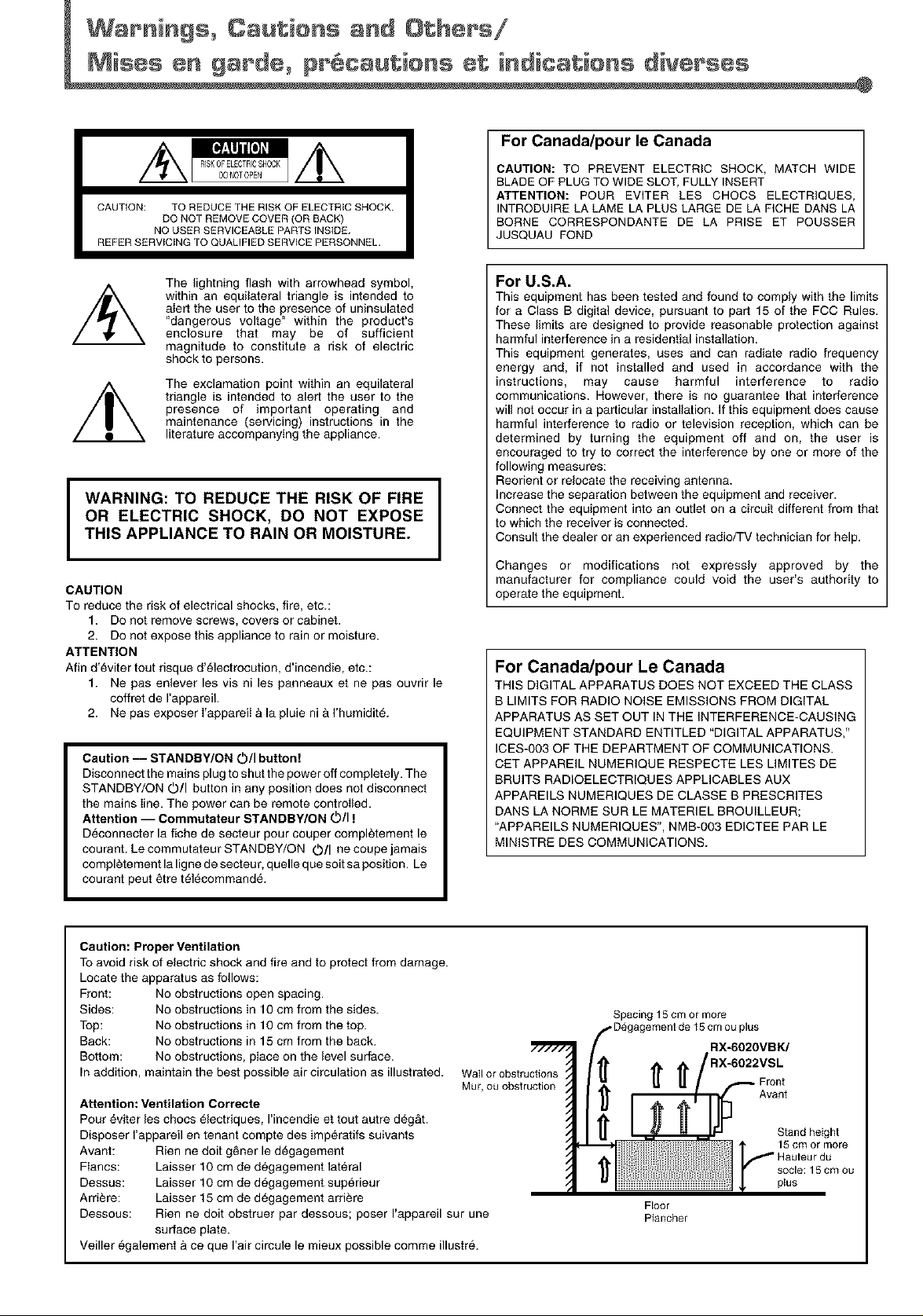
Caution: Proper Ventilation
To avoid risk of electric shock and fire and to protect from damage.
Locate the apparatus as follows:
Front: No obstructions open spacing.
Sides: No obstructions in 10 cm from the sides.
Top: No obstructions in 10 cm from the top.
Back: No obstructions in 15 cm from the back.
Bottom: No obstructions, place on the level surface.
In addition, maintain the best possible air circulation as illustrated.
Attention: Ventilation Correcte
Pour eviter les chocs _lectriques, I'incendie et tout autre deg&t.
Disposer I'appareil en tenant compte des imperatifs suivants
Avant: Rien ne dolt g_ner le d6gagement
Fiancs: Laisser 10 cm de d_gagement lateral
Dessus: Laisser 10 cm de degagement superieur
Arri_re: Laisser 15 cm de degagement arri_re
Dessous: Rien ne dolt obstruer par dessous; poser I'appareil sur une
surface plate.
Veiller egalement & ce que Hair circule le mieux possible comme illustr&
Wallor obstructions
Mur,ou obstruction
Spacing 15 cm or more
RX-6020VBK/
Floor
Plancher
plus
Front
Avant
Stand height
Hauleur du
socle: 15 cm ou
15cm or more
plus
Page 3
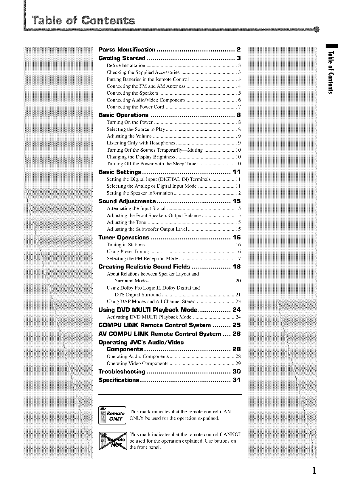
.....__ Parts Identification ...................................... 2 iiiiiiiiiiiiiiiiiiiiiiiiiiiiiiiiiiiiiiiiiiiiiiiiiiiiiiiiiiiiiiiiiiiiiiiiiiiiiiiiiiiiiiiiiiiiiiiiiiiiiiiiiiii
___________________________________________________________________________________________________________ iiiiiiiiiiiiiiiiiiiiiiiiiiiiiiiiiiiiiiiiiiiiiiiiiiiiiiiiiiiiiiiiiiiiiiiiiiiiiiiiiiiiiiiiiiiiiiiiiiiiiiiiiiii
Getting Started ........................................... 3 iiiiiiiiiiiiiiiiiiiiiiiiiiiiiiiiiiiiiiiiiiiiiiiiiiiiiiiiiiiiiiiiiiiiiiiiiiiiiiiiiiiiiiiiiiiiiiiiiiiiiiiiiiii
Beforelnstallation ...................................................................... 3 iiiiiiiiiiiiiiiiiiiiiiiiiiiiiiiiiiiiiiiiiiiiiiiiiiiiiiiiiiiiiiiiiiiiiiiiiiiiiiiiiiiiiiiiiiiiiiiiiiiiiiiiiiii
CheckingtheSuppliedAccessories ........................................... 3 iiiiiiiiiiiiiiiiiiiiiiiiiiiiiiiiiiiiiiiiiiiiiiiiiiiiiiiiiiiiiiiiiiiiiiiiiiiiiiiiiiiiiiiiiiiiiiiiiiiiiiiiiiii
PuttingBatteriesin theRemoteControl .................................... 3 iiiiiiiiiiiiiiiiiiiiiiiiiiiiiiiiiiiiiiiiiiiiiiiiiiiiiiiiiiiiiiiiiiiiiiiiiiiiiiiiiiiiiiiiiiiiiiiiiiiiiiiiiiii
_))))))))))))))))))))))))))))))))))))))))))))))))))))))))))))))))))))))))))))))))))))))))))))))))))))))))))_ColmectingtheFMandaMAntenlms ....................................... 4 iiiiiiiiiiiiiiiiiiiiiiiiiiiiiiiiiiiiiiiiiiiiiiiiiiiiiiiiiiiiiiiiiiiiiiiiiiiiiiiiiiiiiiiiiiiiiiiiiiiiiiiiiiii
ConnectingtheSpeakers ............................................................ 5 iiiiiiiiiiiiiiiiiiiiiiiiiiiiiiiiiiiiiiiiiiiiiiiiiiiiiiiiiiiiiiiiiiiiiiiiiiiiiiiiiiiiiiiiiiiiiiiiiiiiiiiiiiii
Connectingaudio/VideoComponents ....................................... 6 iiiiiiiiiiiiiiiiiiiiiiiiiiiiiiiiiiiiiiiiiiiiiiiiiiiiiiiiiiiiiiiiiiiiiiiiiiiiiiiiiiiiiiiiiiiiiiiiiiiiiiiiiiii
ConnectingthePowerCord ....................................................... 7 iiiiiiiiiiiiiiiiiiiiiiiiiiiiiiiiiiiiiiiiiiiiiiiiiiiiiiiiiiiiiiiiiiiiiiiiiiiiiiiiiiiiiiiiiiiiiiiiiiiiiiiiiiii
m
r
o_.
o
SasicOperatiens.........................................S iiiiiiiiiiiiiiiiiiiiiiiiiiiiiiiiiiiiiiiiiiiiiiiiiiiiiiiiiiiiiiiiiiiiiiiiiiiiiiiiiiiiiiiiiiiiiiiiiiiiiiiiiiii
'lumingOnthePower ................................................................ 8 iiiiiiiiiiiiiiiiiiiiiiiiiiiiiiiiiiiiiiiiiiiiiiiiiiiiiiiiiiiiiiiiiiiiiiiiiiiiiiiiiiiiiiiiiiiiiiiiiiiiiiiiiiii
SelectingtheSourcetoPlay ....................................................... 8 iiiiiiiiiiiiiiiiiiiiiiiiiiiiiiiiiiiiiiiiiiiiiiiiiiiiiiiiiiiiiiiiiiiiiiiiiiiiiiiiiiiiiiiiiiiiiiiiiiiiiiiiiiii
_))))))))))))))))))))))))))))))))))))))))))))))))))))))))))))))))))))))))))))))))))))))))))))))))))))))))))_AdjustingtheVolume ................................................................. 9 iiiiiiiiiiiiiiiiiiiiiiiiiiiiiiiiiiiiiiiiiiiiiiiiiiiiiiiiiiiiiiiiiiiiiiiiiiiiiiiiiiiiiiiiiiiiiiiiiiiiiiiiiiii
ListeningOnlywithHeadphones ............................................... 9 iiiiiiiiiiiiiiiiiiiiiiiiiiiiiiiiiiiiiiiiiiiiiiiiiiiiiiiiiiiiiiiiiiiiiiiiiiiiiiiiiiiiiiiiiiiiiiiiiiiiiiiiiiii
'lurningOfftheSoundsTemporarily Muting ........................ 10 iiiiiiiiiiiiiiiiiiiiiiiiiiiiiiiiiiiiiiiiiiiiiiiiiiiiiiiiiiiiiiiiiiiiiiiiiiiiiiiiiiiiiiiiiiiiiiiiiiiiiiiiiiii
ChangingtheDisplayBrighmess ............................................. 10 iiiiiiiiiiiiiiiiiiiiiiiiiiiiiiiiiiiiiiiiiiiiiiiiiiiiiiiiiiiiiiiiiiiiiiiiiiiiiiiiiiiiiiiiiiiiiiiiiiiiiiiiiiii
'[urningOffthePowerwiththeSleepTinaer ........................... 10 iiiiiiiiiiiiiiiiiiiiiiiiiiiiiiiiiiiiiiiiiiiiiiiiiiiiiiiiiiiiiiiiiiiiiiiiiiiiiiiiiiiiiiiiiiiiiiiiiiiiiiiiiiii
nasicSettings...........................................11 iiiiiiiiiiiiiiiiiiiiiiiiiiiiiiiiiiiiiiiiiiiiiiiiiiiiiiiiiiiiiiiiiiiiiiiiiiiiiiiiiiiiiiiiiiiiiiiiiiiiiiiiiiii
_))))))))))))))))))))))))))))))))))))))))))))))))))))))))))))))))))))))))))))))))))))))))))))))))))))))))))_SettingtheDigitalh_put(DIGITaLIN)Ternailmls ................. 11 iiiiiiiiiiiiiiiiiiiiiiiiiiiiiiiiiiiiiiiiiiiiiiiiiiiiiiiiiiiiiiiiiiiiiiiiiiiiiiiiiiiiiiiiiiiiiiiiiiiiiiiiiiii
iiiiiiiiiiiiiiiiiiiiiiiiiiiiiiiiiiiiiiiiiiiiiiiiiiiiiiiiiiiiiiiiiiiiiiiiiiiiiiiiiiiiiiiiiiiiiiiiiiiiiiiiiiiSelectingtheanalogorDigitallnputMode ............................ 11 iiiiiiiiiiiiiiiiiiiiiiiiiiiiiiiiiiiiiiiiiiiiiiiiiiiiiiiiiiiiiiiiiiiiiiiiiiiiiiiiiiiiiiiiiiiiiiiiiiiiiiiiiiii
SettingtheSpeakerlnformation ............................................... 12 iiiiiiiiiiiiiiiiiiiiiiiiiiiiiiiiiiiiiiiiiiiiiiiiiiiiiiiiiiiiiiiiiiiiiiiiiiiiiiiiiiiiiiiiiiiiiiiiiiiiiiiiiiii
SeundAdjustments....................................lS iiiiiiiiiiiiiiiiiiiiiiiiiiiiiiiiiiiiiiiiiiiiiiiiiiiiiiiiiiiiiiiiiiiiiiiiiiiiiiiiiiiiiiiiiiiiiiiiiiiiiiiiiiii
AttenuatingthelnputSignal .................................................... 15 iiiiiiiiiiiiiiiiiiiiiiiiiiiiiiiiiiiiiiiiiiiiiiiiiiiiiiiiiiiiiiiiiiiiiiiiiiiiiiiiiiiiiiiiiiiiiiiiiiiiiiiiiiii
AdiustingtheFrontSpeakersOutputBalance ......................... 15 iiiiiiiiiiiiiiiiiiiiiiiiiiiiiiiiiiiiiiiiiiiiiiiiiiiiiiiiiiiiiiiiiiiiiiiiiiiiiiiiiiiiiiiiiiiiiiiiiiiiiiiiiiii
adiustingtheTone ................................................................... 15 iiiiiiiiiiiiiiiiiiiiiiiiiiiiiiiiiiiiiiiiiiiiiiiiiiiiiiiiiiiiiiiiiiiiiiiiiiiiiiiiiiiiiiiiiiiiiiiiiiiiiiiiiiii
Adiusting the Subwoofer Output Level .................................... 15 iiiiiiiiiiiiiiiiiiiiiiiiiiiiiiiiiiiiiiiiiiiiiiiiiiiiiiiiiiiiiiiiiiiiiiiiiiiiiiiiiiiiiiiiiiiiiiiiiiiiiiiiiiii
,unerOperatiens.......................................16 iiiiiiiiiiiiiiiiiiiiiiiiiiiiiiiiiiiiiiiiiiiiiiiiiiiiiiiiiiiiiiiiiiiiiiiiiiiiiiiiiiiiiiiiiiiiiiiiiiiiiiiiiiii
TuninginStations .................................................................... 16 iiiiiiiiiiiiiiiiiiiiiiiiiiiiiiiiiiiiiiiiiiiiiiiiiiiiiiiiiiiiiiiiiiiiiiiiiiiiiiiiiiiiiiiiiiiiiiiiiiiiiiiiiiii
_._Pre_etWun_._................................................................._6 iiiiiiiiiiiiiiiiiiiiiiiiiiiiiiiiiiiiiiiiiiiiiiiiiiiiiiiiiiiiiiiiiiiiiiiiiiiiiiiiiiiiiiiiiiiiiiiiiiiiiiiiiiii
_e,e_t_ngtbe_M_e_ept_onMo,_e..........................................._ iiiiiiiiiiiiiiiiiiiiiiiiiiiiiiiiiiiiiiiiiiiiiiiiiiiiiiiiiiiiiiiiiiiiiiiiiiiiiiiiiiiiiiiiiiiiiiiiiiiiiiiiiiii
................................. iiiiiiiiiiiiiiiiiiiiiiiiiiiiiiiiiiiiiiiiiiiiiiiiiiiiiiiiiiiiiiiiiiiiiiiiiiiiiiiiiiiiiiiiiiiiiiiiiiiiiiiiiiii
iiiiiiiiiiiiiiiiiiiiiiiiiiiiiiiii:i! Using Dolby Pro Logic 11,Dolby Digital and iiiiiiiiiiiiiiiiiiiiiiiiiiiiiiiiiiiiiiiiiiiiiiiiiiiiiiiiiiiiiiiiiiiiiiiiiiiiiiiiiiiiiiiiiiiiiiiiiiiiiiiiiiii
Creating _ea_isticSeund rie_ds................... lS iiiiiiiiiiiiiiiiiiiiiiiiiiiiiiiiiiiiiiiiiiiiiiiiiiiiiiiiiiiiiiiiiiiiiiiiiiiiiiiiiiiiiiiiiiiiiiiiiiiiiiiiiiii
About Relations between Speaker Layout and iiiiiiiiiiiiiiiiiiiiiiiiiiiiiiiiiiiiiiiiiiiiiiiiiiiiiiiiiiiiiiiiiiiiiiiiiiiiiiiiiiiiiiiiiiiiiiiiiiiiiiiiiiii
Surround Modes ................................................................. 20 iiiiiiiiiiiiiiiiiiiiiiiiiiiiiiiiiiiiiiiiiiiiiiiiiiiiiiiiiiiiiiiiiiiiiiiiiiiiiiiiiiiiiiiiiiiiiiiiiiiiiiiiiiii
DTSDigitalSurround ........................................................ 21 iiiiiiiiiiiiiiiiiiiiiiiiiiiiiiiiiiiiiiiiiiiiiiiiiiiiiiiiiiiiiiiiiiiiiiiiiiiiiiiiiiiiiiiiiiiiiiiiiiiiiiiiiiii
UsingDAPaodesandAII Cham_el Stereo ............................. 23 ............................................................................................................
Using"vo MU,'rlmay',ac_Mede................a4
ActivatingDVDMUUFIPlaybackMode,, ................................ 24
COMPU LINKRemote Control System ......... 25
iiiiiiiiiiiiiiiiiiiiiiiiiiiiiiiiiiiiiiiiiiiiiiiiiiiiiiiii:!!_iiiiiiiiiiiiiiiiiiiiiiiiiiiiiiiiiiiiiiiiiiiiiiiiiiiiiiiiiiiiiiiiiiiiiiiiiiiiiiiiiiiiiiiiiiiiiiiiiiiAVCOMPU LINKRemoteContro, System .... 26
Operating JVCs Audio/Video
Components .......................................... 28
OperatingAudioComponents,,,, .................................................. 28
OperatingVideoComponents .................................................. 29
iiiiiiiiiiiiiiiiiiiiiiiiiiiiiiiiiiiiiiiiiiiiiiiiiiiiiiiiiiiiiiiiiiiiiiiii_i:i!_iiiiiiiiiiiiiiiiiiiiiiiiiiiiiiiiiiiiiiiiiiiiiiiiiiiiiiiiiiiiiiiiiiiiiiiiiiiiiiiiiiiiiiiiiiiiiiiiiiiiiiiTreu_Ies|,eeting.........................................aO
iiiiiiiiiiiiiiiiiiiiiiiiiiiiiiiiiiiiiiiiiiiiiiiiiiiiiiiiiiiii!ii!iiiiiiiiiiiiiiiiiiiiiiiiiiiiiiiiiiiiiiiiiiiiiiiiiiiiiiiiiiiiiiSpecificatiens............................................a1
__________________________________________________________________________________________i_i!_i!iiii_ ThismarkindicatesthattheremotecontrolCAN
L_ o_tYj ONLYbeusedfortheoperationexplained.
!!!!!!!!!!!!!!!!!!!!!!!!!!!!!!!!!!!!!!!!!!!!!!!!!!!!!!!!!!!!!!!!!!!!!!!!!!!!!!!!!!!!!!!!!!!!!!!!!!
iiiiiiiiiiiiiiiiiiiiiiiiiiiiiiiiiiiiiiiiiiiiiiiiiiiiiiiiiiiiiiiiiiiiiiiiiiiiiiiiiiiiiiiiiiiiiiiiiiiiibeusedfortheoperationexplained. Usebuttonson
iiiiiiiiiiiiiiiiiiiiiiiiiiiiiiiiiiiiiiiiiiiiiiiiiiiiiiiiiiiiiiiiiiiiiiiiiiiiiiiiiiiiiiiiiiiiiiiiii!!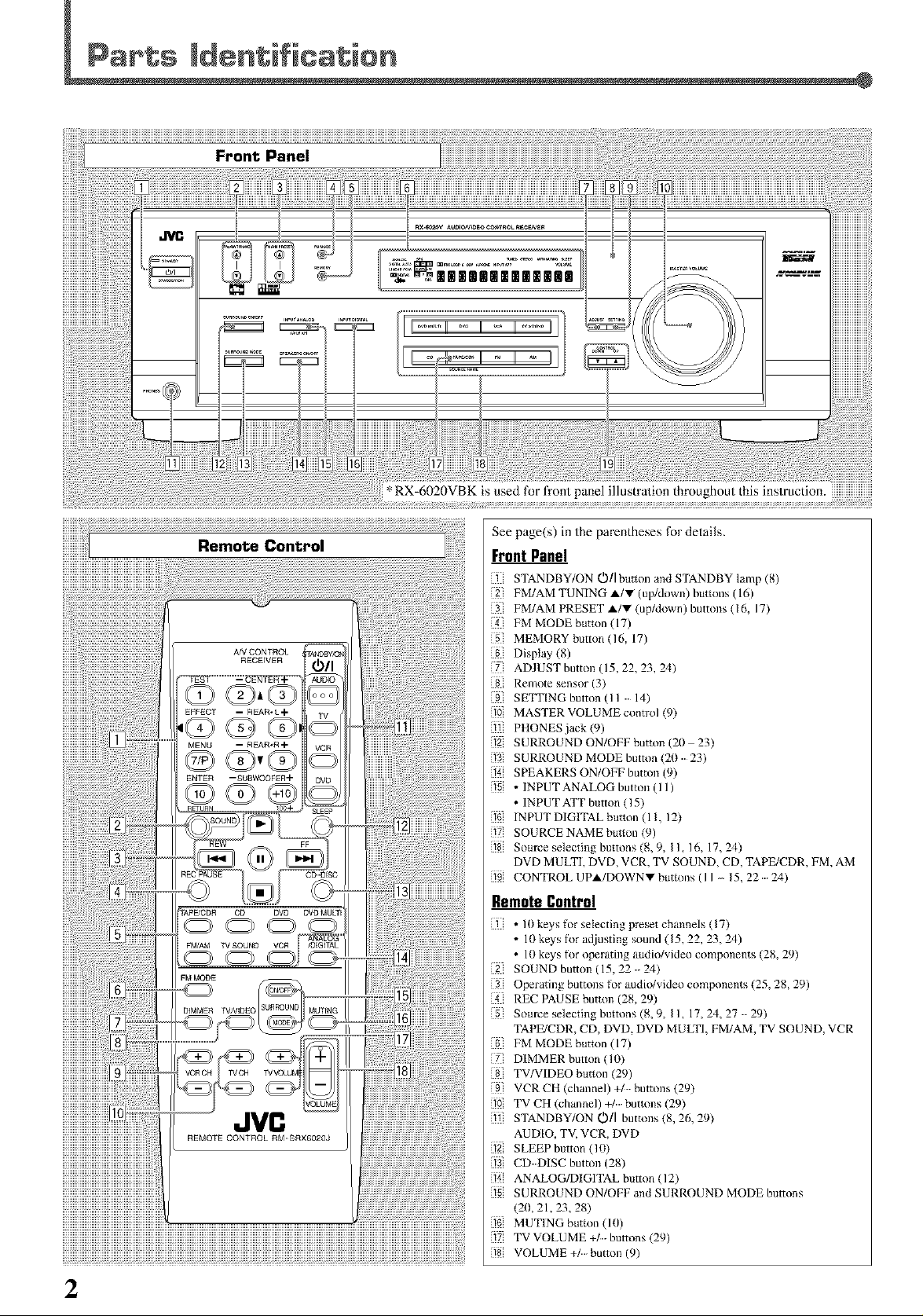
TVCH
JVC
See page(s) in the parentheses for details.
Front Panel
STANDBY/ON O/i button and STANDBY lamp (8,)
FM/AM TUNING A/V (up/down) buttons (16)
FM/AM PRESET A/V (up/down) buttons 416, 17)
FM MODE button (17)
5[ MEMORY button(16, 17)
Display (8)
] ADJUST button ( 15, 22, 23, 24)
Remote sensor (3)
SE_PlNG button (11 14)
10 MASTER VOLUME control (9)
PHONES jack (9)
12 SURROUND ON/OFF button (20 23)
13 SURROUND MODE button 420 23)
1_ SPEAKERS ON/OFF bmttm (9)
5 • INPUT ANALOG button ( I I)
• IN PUT ATT button (15)
16 INPUTDIGITALbutton(II, 12)
{17 SOURCENAME button (9)
8 Som-ce selecting buttons (8, 9, II, 16, 17,24)
DVD MULTI, DVD, VCR, TV SOUND, CD, TAPE/CDR, FM, AM
9 CONTROLUPA/DOWNVbuttons(II_ 15,22 24)
Remote Contro|
• 10 keys for selecting preset channels 417)
• 10 keys lk)r adjusting sound (15, 22, 23, 24)
• 10 keys Ik)r operating audio/video components (28, 29)
2] SOUND button (15, 22 24)
Operating buttons for audio/video components (25, 28, 29)
REC PAUSE button (28, 29)
Som-ce selecting buttons (8, 9, II, 17,24_ 27 29)
TAPE/CDR, CD, DVD, DVD MULTI, FM/AM, TV SOUND,VCR
FM MODE button (17)
] DIMMER button 410)
TV/VIDEO button (29)
9 VCRCHIchannel)+/ buttons429)
10 TV CH (channel) buttons (29)
STANDBY/ON OIl buttons 48, 26, 29)
AUDIO, TV, VCR, DVD
12 SLEEP button (10)
13 CD DISC button (28)
14 ANALOG/DIGITAL button 412)
5 SURROUND ON/OFF and SURROUND MODE buttons
420, 21,23, 28)
_ MUTING blmon (ltI)
? TVVOLUME +/buttons (29)
8 VOLUME +/button (9)
2
Page 5
/
1U
_t
General Precautions
• DO NOT insert any metal o_ect to the unit.
• DO NOT disassemble the unit or remove screws, covers, or
cabinet.
• DO NOT expose the unit to rain or moisture.
Locations
• Install the unit in a location that is level and prolected fl-om
moisture.
• The lemperature around the unit must be between 5°C and 35_'C
(23°F and 95°F).
• Make sure there is good ventilation around the unit. Poor
ventila/ion could cause overhea/ing and damage the unit.
Handling the unit
• DO NOT touch the power co_ with wet hands.
• DO NOT pull the power cord to unplug the cord. When
unplugging the cord, always grasp the plug so as not to damage
the cord.
• Keep the power cord away fiom the connecting cords and the
anlenna. The power cord may cause noise or screen interference. It
is recommended to use a coaxial cable for anlenna connection,
since it is well-shielded against interference.
• When a power failure occurs, or when you unplug the power cord,
the preset sellings such as preset FM/AM channels and sound
ac[justments may be erased in a few days.
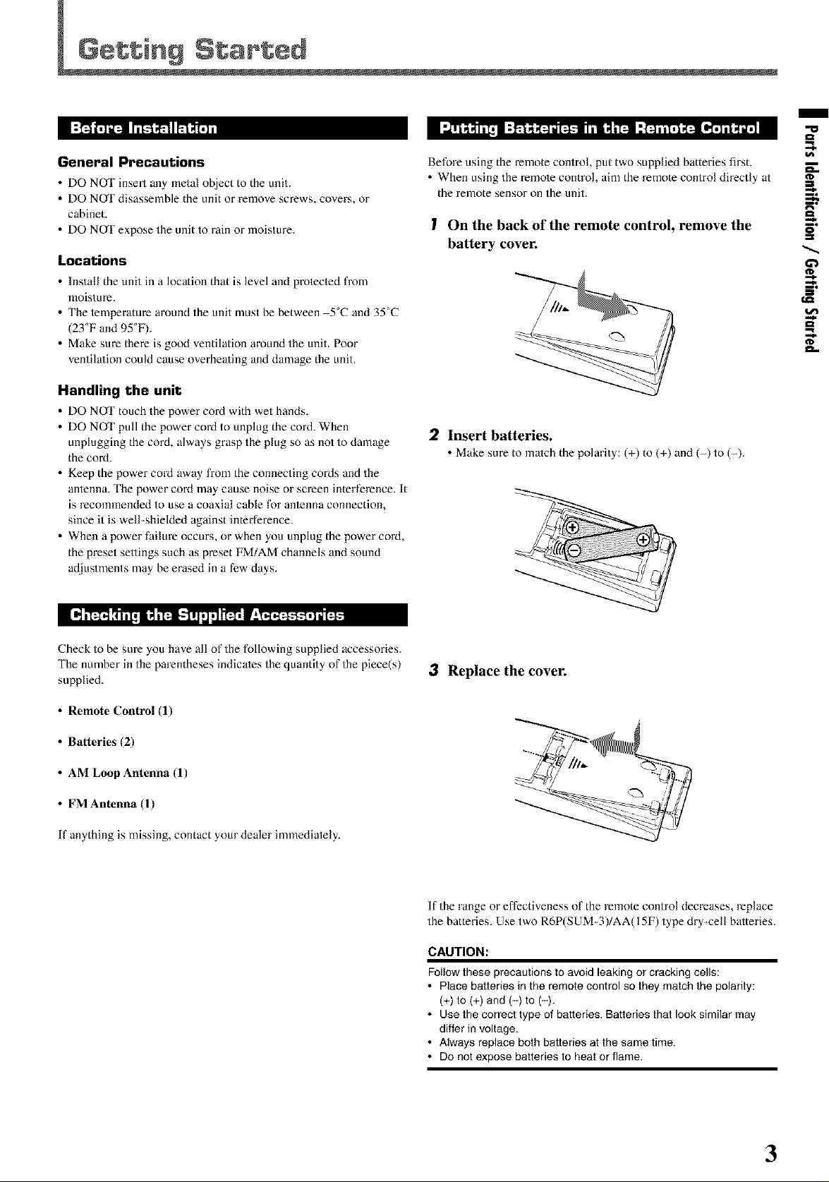
Before using the remote control, put two supplied batteries first.
• When using the remole control, aim the remote control directly at
the remote sensor on the unit.
I On the back of the remote control, remove the
battery cover.
2 Insert batteries.
• Makesure to match the polarity: (+) to (+) anti (-) to (-).
¢D
=_
5"
gl
gl
€,Q
O't
[_,"t_ITT_ l _,"t_-T!l,j :1i_, F:_
Check to be sure you have all of the following supplied accessories.
The number in the parentheses indicales the quantity of the piece(s)
supplied.
• Remote Control (1)
• Batteries (2)
• AM Loop Antenna (1)
• FM Antenna (1)
If anything is missing, contact your dealer immediately.
3 Replace the cover.
If the range or effectiveness of the remote control decreases, replace
the batteries. Use two R6P(SUM-3)/AA(15F) type dry-cell batteries.
CAUTION:
Follow these precautions to avoid leaking or cracking cells:
• Place batteries in the remote control so they match the polarity:
(+) to (+) and (-) to (-).
• Use the correct type of batteries. Batteries that look similar may
differ in voltage.
• Always replace both batteries at the same time.
• Do not expose batteries to heat or flame.
3
Page 6
Getting Started
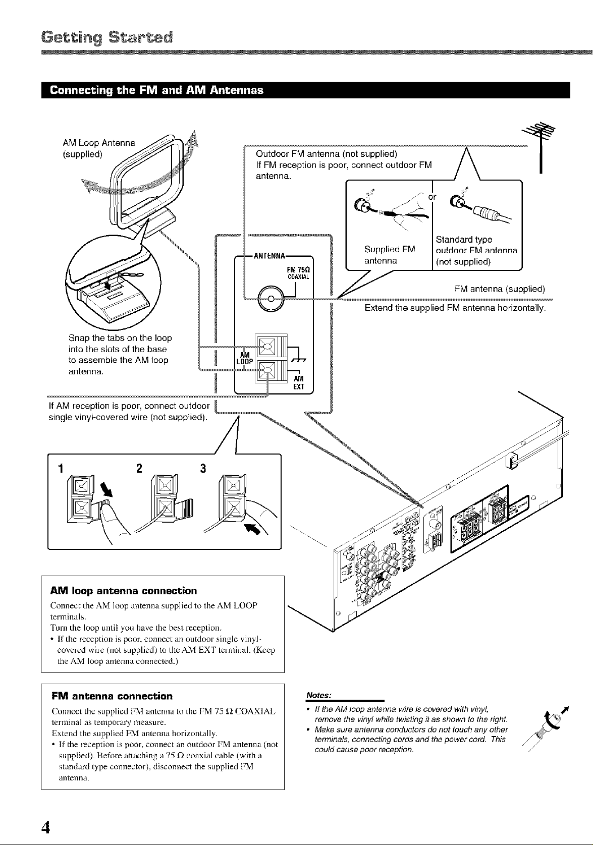
AM Loop Antenna
(supplied)
Outdoor FM antenna (not supplied)
If FM reception is poor, connect outdoor FM
antenna.
Supplied FM outdoor FM antenna
antenna (not supplied)
Extend the supplied FM antenna horizontally.
Snap the tabs on the loop
into the slots of the base
to assemble the AM loop
antenna.
If AM reception is poor, connect outdoor
single vinyl-covered wire (not supplied). A
/L
3
AM loop antenna connection
Connect the AM loop antenna supplied to the AM LOOP
terminals.
'lure the loop until you have the best reception.
If the reception is poor, connect an outdoor single vinyl-
covered wire (not supplied) to the AM EXT terminah (Keep
the AM k)op antenna connected.)
EXT
FM antenna connection
Connect the supplied FM antenna to the FM 75 £_ COAXIAL
terminal as temporary measm-e.
Extend the supplied FM antenna horizontally.
• If the reception is poor, connect an outdoor FM antenna (not
supplied). Before attaching a 75 £_ coaxial cable (with a
standard type connector), disconnect the supplied FM
antenna.
4
Notes:
• If the AM loop antenna wire is covered with vinyl,
remove the viny! while twisting it as shown to the righL
• Make sure antenna conductors do not touch any other
terminals, connecting cords and the power cord. This
could cause poor reception.
Page 7
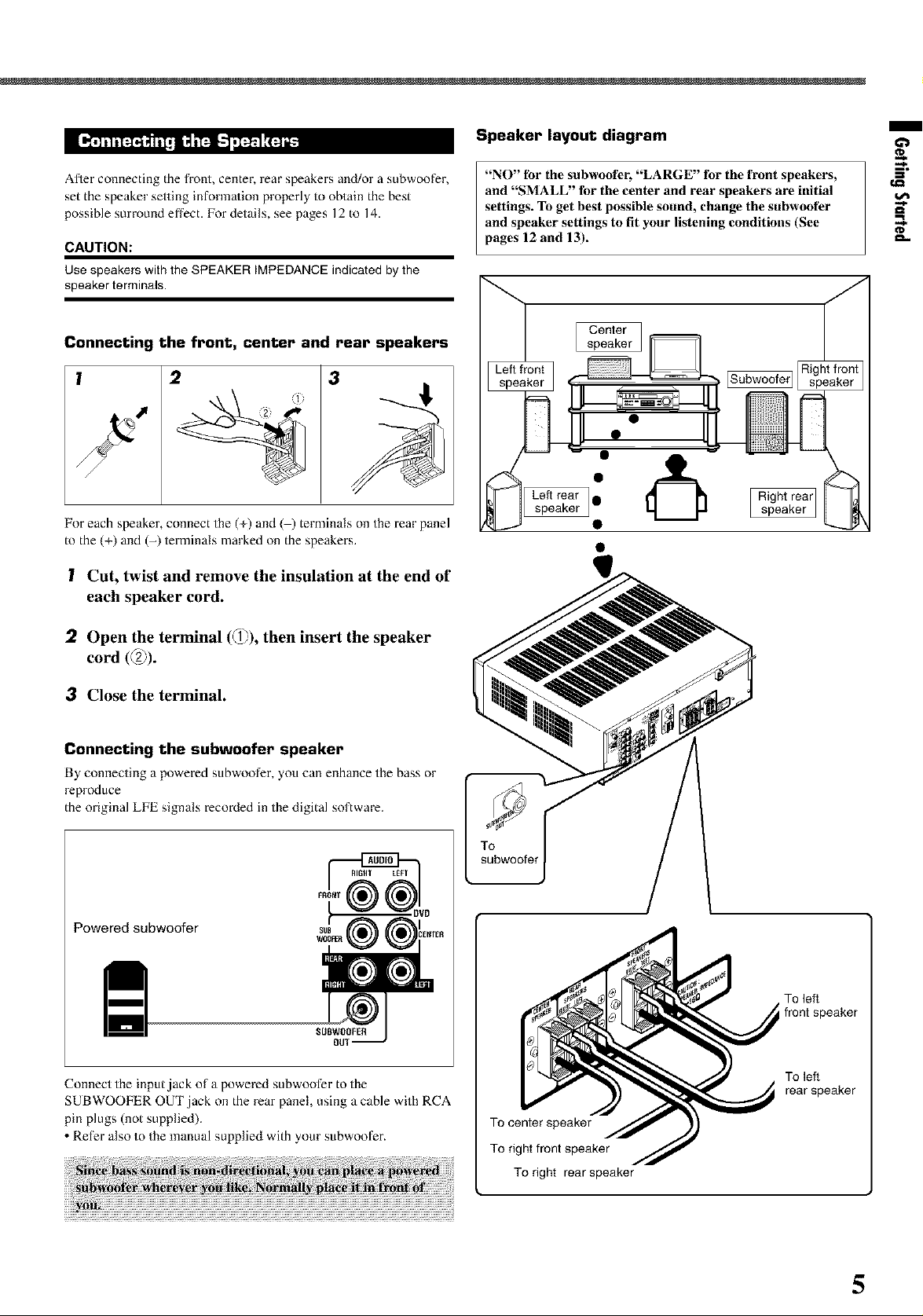
Speaker layout diagram
/
Afler connecting the front, center, rear speakers and/or a subwoofer,
set the speaker setting information properly to obtain the best
possible surround effect. For details, see pages 12 to 14.
CAUTION:
Use speakers with the SPEAKER IMPEDANCE indicated by the
speaker terminals.
Connecting the front, center and rear speakers
l 2
For each speaker, connect the (+) and ( ) terminals on the rear panel
to the (+) and (-) terminals marked on the speakers.
3
(il
! Cut, twist and remove the insulation at the end of
each speaker cord.
"NO" fbr the subwoofer, "LARGE" for the front speakers,
and "SMALL" fbr the center and rear speakers are initial
settings. To get best possible sound, change the subwoofer
and speaker settings to fit your listening conditions (See
pages 12 and 13).
[Subwoofer]
Left rear •
speaker speaker
"&
] I Right rear
gl
:2 Open the terminal (d_J),r'_then insert the speaker
cord (_2_).
3 Close the terminal.
Connecting the subwoofer speaker
By connecting a powered subwoofer, you can enhance the bass or
reproduce
the original LIE signals recoMed in the digital software.
Powered subwoofer
SUBWOOFER
OU1
Connect the input.jack of a powered subwoofer to the
SUBWOOFER OUT jack on the rear panel, using a cable with RCA
pin plugs (not supplied).
• Ret%r also to the manual supplied with your subwoot_r.
To left
front speaker
To left
rear speaker
To center speaker
To right front speaker
To right rear speaker
5
Page 8
Getting Started
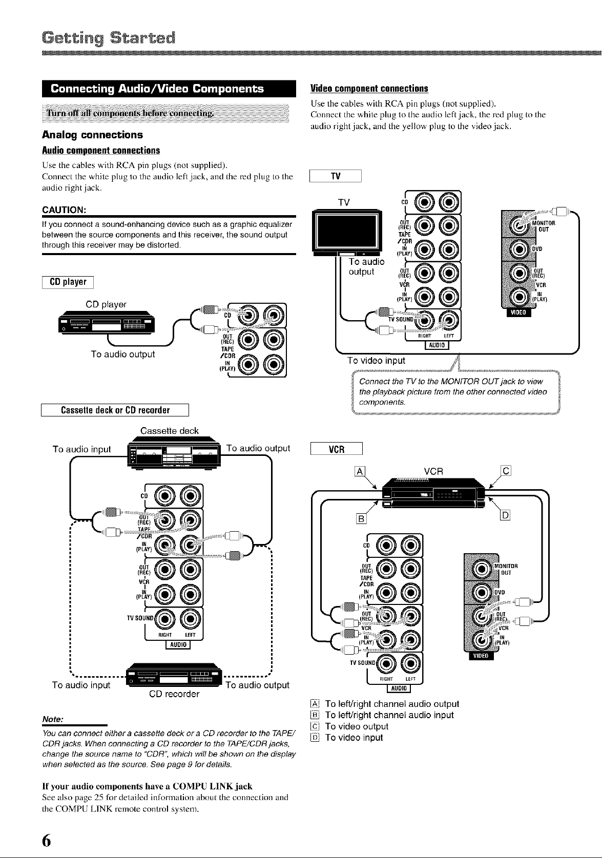
Analog connections
Audiocomponentconnections
Use the cables with RCA pin plugs (not supplied).
Connect the while plug to the audio left,jack, and the red plug to the
audio right ,jack.
CAUTION:
If you connect a sound-enhancing device such as a graphic equalizer
between the source components and this receiver, the sound output
through this receiver may be distorted.
[ CDplayer 1
CD player
Videocomponent connections
Use the cables with RCA pin plugs (not supplied).
Comlect the white plug to the audio left jack, the red plug to the
audio right jack, and the yellow plug to the video jack.
TV
TV
To audio
output
I
_CR
IN
To audio output
Cassettedeckor CDrecorder
Cassette deck
To audio input
TAPE
/CDR
To audio output
To video input
VCR
;onnect the TV to the MONITOFt OUT jack to view
the playback picture from the other connected video
components.
r
CO
OUT
(REC) (
TAPE
/CDR
iN I
(PLAY)
CD recorder
Note:
You can connect either a cassette deck or a CD recorder to the TAPE/
CDFt jacks. When connecting a CD recorder to the TAPE/CDR jacks,
change the source name to "CDR'; which will be shown on the display
when selected as the source. See page 9 for details.
If your audio components have a COMPU LINK jack
See also page 25 for detailed information about the connection and
the COMPU LINK remote control system.
6
IA, To left/right channel audio output
To left/right channel audio input
To video output
To video input
Page 9
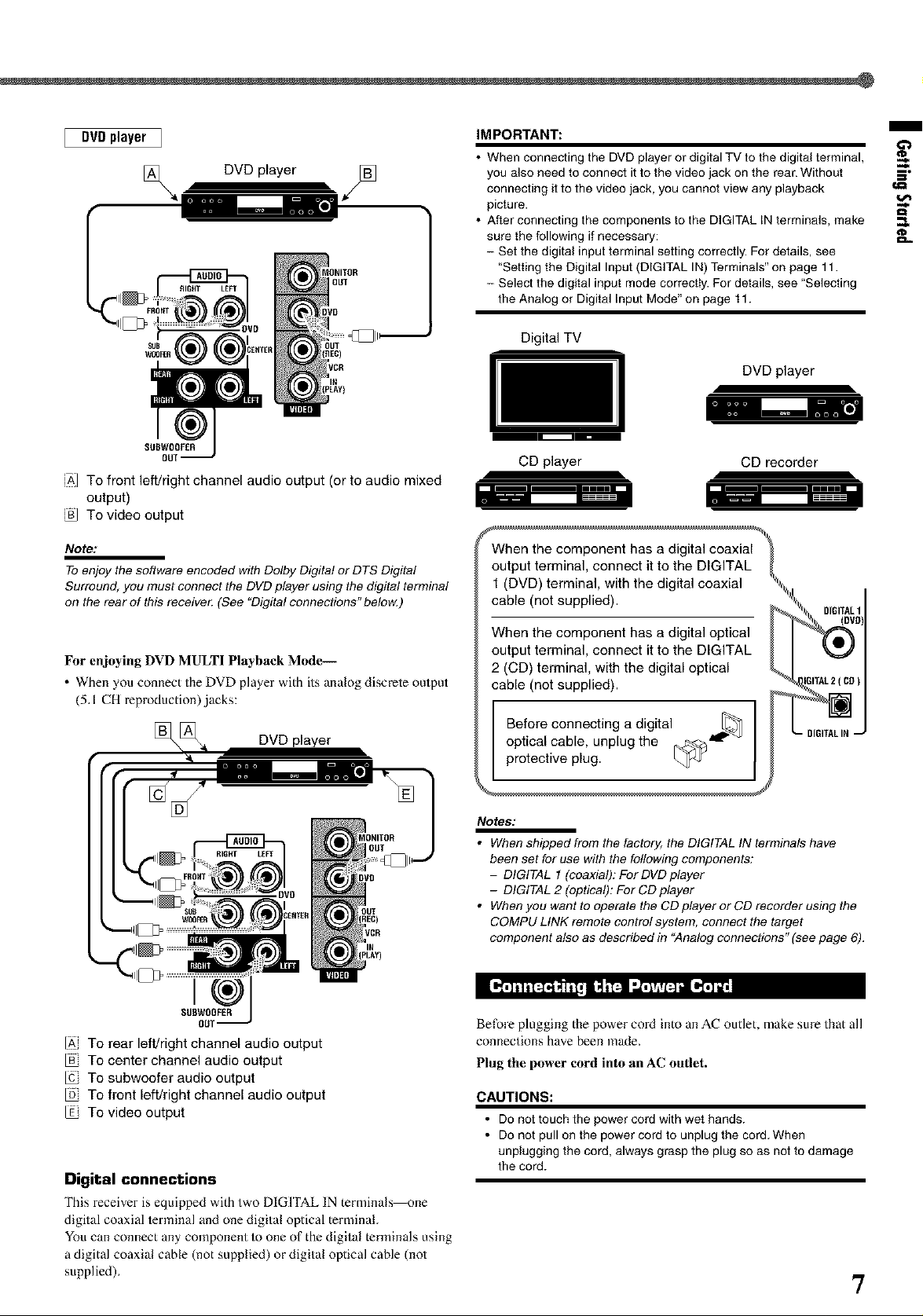
DVDplayer I
[_ DVD player
OUT
FRO_T
SUBWOOF£R
OUl
iA] To front left/right channel audio output (or to audio mixed
output)
To video output
IMPORTANT:
• When connecting the DVD player or digital TV to the digital terminal,
you also need to connect it to the video jack on the rear. Without S"
connecting it to the video jack, you cannot view any playback t,a
picture.
• After connecting the components to the DIGITAL IN terminals, make
sure the following if necessary: _..
- Set the digital input terminal setting correctly. For details, see
"Setting the Digital Input (DIGITAL IN) Terminals" on page 11.
- Select the digital input mode correctIy. For details, see "Selecting
the Analog or Digital Input Mode" on page 11.
Digital TV
DVDplayer
CD player
CD recorder
/
Note:
TOenjoy the software encoded with Dolby Digital or DTS Digital
Surround, you must connect the DVD player using the digital terminal
on the rear of this receive_ (See "Digital connections" below.)
For enjoying DVD MULTI Playback Mode-
. When you connect the DVD player with its analog discrete output
(5.1 CH reproduction)jacks:
[_[_ DVD player
}CR
IN
(PLAY)
IV
SEll]WOOFER
ou1
IA, To rear left/right channel audio output
To center channel audio output
To subwoofer audio output
To front left/right channel audio output
To video output
Digital connections
This receiver is equipped with two DIGITAL IN terminals--one
digital coaxial ierminal and one digital optical terminal.
You can connect any component to one of the digital terminals using
a digital coaxial cable (not supplied) or digital optical cable (not
supplied).
When the component has a digital coaxial
output terminal, connect it to the DIGITAL
1 (DVD) terminal, with the digital coaxial
cable (not supplied).
When the component has a digital optical
output terminal, connect it to the DIGITAL
2 (CD) terminal, with the digital optical
cable (not supplied).
Before connecting a digital
optical cable, unplug the _._<J
protective plug.
Notes:
• When shipped from the factory, the DIGITAL IN terminals have
been set for use with the following components:
- DIGITAL 1 (coaxial): For DVD player
- DIGITAL 2 (optical): For CD player
• When you want to operate the CD player or CD recorder using the
COMPU LINK remote contro! system, connect the target
component also as described in "Analog connections" (see page 6).
Before plugging the power cord into an AC outlet, make sure that all
connections have been made.
Plug the power cord into an AC outlet.
CAUTIONS:
• Do not touch the power cord with wet hands.
• D° n°t pull °n the p°wer c°rd t° unplug the c°rd When
unplugging the cord, always grasp the plug so as not to damage
the cord.
7
Page 10
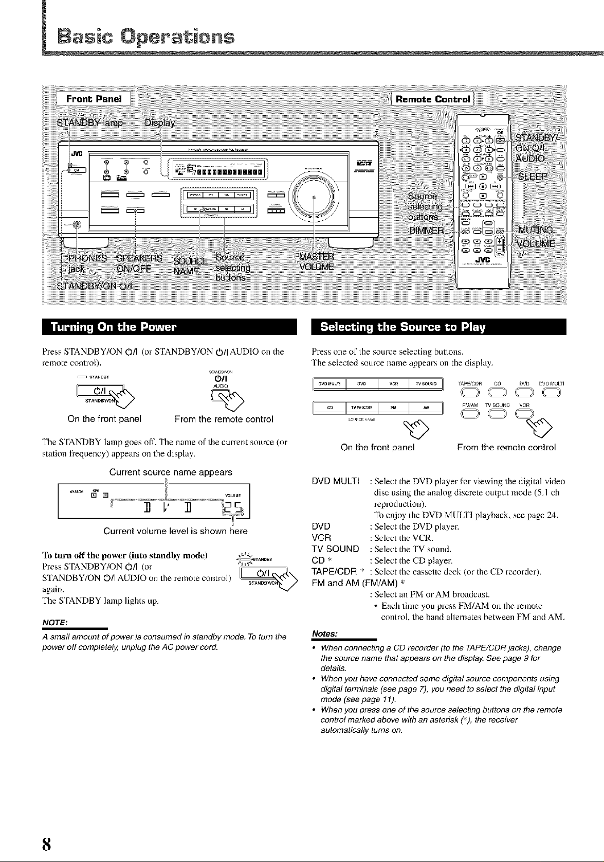
Front Panel
g_ F'_I'_I_:j_ ,"_g'.P'r!lT'_ FFZ:,IE"Vj/ l'!l"_'_J [e_ i"_I'_ I".Z'_T_
Press STANDBY/ON O/I (or STANDBY/ON O/I AUDIO on the
remote control).
On the front panel From the remote control
The STANDBY lamp goes off. The name of the current source (or
station frequency) appears on the display.
I i
AJDI O
Current source name appears
..... " 1
]] V 11
Current volume level is shown here
To turn off the power (into standby mode) _
Press STANDBY/ON O/I (or _'_*
STANDBY/ON O/I AUDIO on the re note control) _
again. ST_BWO_/
The STANDBY lamp lights up.
NOTE:
A small amount of power is consumed in standby mode, To turn the
power off completely, unplug the AC power cord.
,,_TANDSy
Press one of the source selecting buttons.
'Ihe selected source name appears on the display.
_P_CDR CD DVD DVDMU_I
FMJAM TV SOUND VCR
On the front panel
DVD MULTI : Select the DVD player for viewing the digital video
disc using the analog discrete output mode (5A ch
reproduction).
To enjoy the DVD MULTI playback, see page 24.
DVD : Select the DVD player.
VCR : Select the VCR.
TV SOUND : Select the TV sound.
CD * : Select the CD player.
TAPE/CDR * : Select the cassette deck (or the CD recorder).
FM and AM (FM/AM) *
: Select an FM orAM broadcast.
• Each time you press FM/AM on the x-creole
control, the band alternates between FM and AM.
Notes:
• When connecting a CD recorder (to the TAPE/CDR jacks), change
the source name that appears on the display. See page 9 for
details.
• Whenyouhavecennectedsomedigitalsourcecomponentsusing
digital terminals (see page 7), you need to select the digital input
mode (see page 11).
• Whenyoupressoneofthesourceselectingbuttonsontheremote
control marked above with an asterisk (_), the receiver
automatically turns on.
From the remote control
8
Page 11
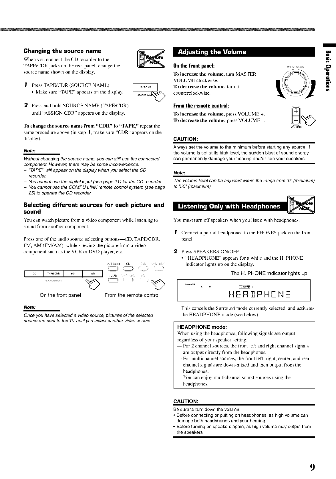
Changing the source name
When you connect the CD recorder to the
TAPE/CDR jacks on the rear panel, change the
source name shown on the display.
1 Press TAPE/CDR (SOURCE NAME).
• Make sure "TAPE" appears on the display.
On the front panel:
To increase the volume, turn MASTER
VOLUME clockwise.
To decrease the volume, turn it
counterclockwise.
/
O
I
2 Press and hold SOURCE NAME (TAPE/CDR)
until "ASSIGN CDR" appears on the display.
To change the source name from "CDR" to "TAPE," repeat the
same procedure above (in step I, make sure "CDR" appears on the
display).
Note:
Without changing the source name, you can still use the connected
component. However, there may be some inconvenience;
- 'TAPE" will appear on the display when you select the CD
recordo_
- You cannot use the digital input (see page ! I) for the CD recorde_
- You cannot use the COMPU LINK remote control system (see page
25) to operate the CD recorde_
Selecting different sources for each picture and
sound
You can watch picture from a video component while listening to
sound from another component.
Press one of the audio source selecting buttons_D, TAPE/CDR,
FM, AM (FM/AM), while viewing the picture from a vide()
component such as the VCR or DVD player, etc.
TApFJCDR CD
I °° II.......II II °° i
[rom theremotecontrol:
To increase tile volume, press VOLUME +. _+=_r-...4_
To decrease the volume, press VOLUME
VOLUME
CAUTION:
Always set the volume to the minimum before starting any source. If
the volume is set at its high level, the sudden blast of sound energy
can permanently damage your hearing and/or ruin your speakers.
Note:
The volume level can be adjusted within the range from "0" (minimum)
to "50" (maximum).
You must turn off speakers when you listen with headphones.
1 Connect a pair of headphones to the PHONES .jack on the front
panel.
2. Press SPEAKERS ON/OFE
• "HEADPHONE" appears for a while and the H. PHONE
indicator lights up on the display.
The H. PHONE indicator lights up.
On the front panel From the remote control
Note:
Once you have selected a video source, pictures of the selected
source are sent to the TV until you select another video source.
I--IER P I--ID,NE
This cancels the Surround mode currently selected, and activates
the HEADPHONE mode (see below).
HEADPHONE mode:
When using the headphones, following signals are output
regardless of your speaker selling:
-- Pbr 2 channel sources, the fi-ont left and right channel signals
are oulput directly fiom the headphones.
-- For multichannel sources, the fi-ont left, right, center, and rear
channel signals are down-mixed and then output from the
headphones.
You can enjoy multichannel sound sources using the
headphones.
CAUTION:
Be sure to turn down the volume:
• Before connecting or putting on headphones, as high volume can
damage both headphones and your hearing.
• Before turning on speakers again, as high volume may output from
the speakers.
9
Page 12

Basic Operations
You can mute the sound temporarily.
Press MUTING on the remote control to mute MUT_Na
the sound through all speakers or headphones _=_-_
connected.
• "MUTING" appears on the display and the volume
turns off (the volume level indicator goes off).
h41 IT Tl_lr
IIU i ±l_lk21
To restore the sound, press MUTING again.
• Turning MASTER VOLUME on the front panel or pressing
VOLUME +/- on the rentote control also restores the sound.
Remote
ONLY
You can dim the display.
Press DIMMER on the remote control. DIMMER
• Each time you press the button, the display dims and _N)
brightens alternately.
,..,,/
Basicadjustmentautomemorg
'Ihis receiver memorizes sound settings for each source when:
• Turning offthe power,
• Changing the source, and
• Assigning the source name.
When you change the source, the memorized settings for the newly
sele[]ed source are automatically recalled.
IZk)llowing can be stored for each source:
lnput attenuator mode (see page 15)
Balance (see page 15)
Tone ac[justment (see page 15)
Subwoofer output level (see page 15)
Surround mode selection (see page 21-23)
tetes:
You cannot assign and store different settings for digital input mode
and analog input mode.
If the source is FM or AM, you can assign a different setting for
each band.
For recording
You can record any source playing through the receiver to a cassette
deck (or a CD recorder) conne[]ed to the TAPE/CDR,jacks and the
VCR connected to the VCR ,jacks at the same time.
While recording, you can listen to the selected sound source at
whatever sound level you like without affecting the sound levels of
the recording.
Note:
The output leve!, tone adjustment (see page 15), and Surround
modes (see page 21-23) cannot affect the recording,
You can fall asleep while listening to music Sleep Timer.
Press SLEEP on the remote control repeatedly, sL_,,
• The SLEEP indicator lights up on the display, and the _x_'>
shut-off time changes in 10 minutes intervals.
SLEEP 50HIN
When the shut-off time comes
'lhe receiver turns off automatically.
To check or change the time remaining before the shut-off time
Press SLEEP once.
'Ihe remaining time (in minutes) until the shut-off time appears.
• To change the shut-offtime, press SLEEP repeatedly until
preferred remaining time appears on the display.
To cancel the Sleep Timer
Press SLEEP repeatedly until "SLEEP 0 MIN" appears on the
display. (The SLEEP indicator goes off.)
• Turning offthe power also cancels the Sleep Timer.
Signalandspeakerindicators onthedisplag
Signal indicators Speaker indicators
(lll
The following signal indicators light up--:
L : • When digital input is selected: Lights up when the left
channel signal comes in.
• When analog input is selected: Always lights up.
R : • When digital input is selected: Lights up when the right
channel signal comes in.
• When analog input is selected: Always lights up.
C : When the ce[]er channel signal comes in.
LS : When theleflrearchannelsignalcomesin.
RS : When the right rear channel signal comes in.
S : When the monam-al rear channel signal or 2 ch Dolby
Surround encoded signal comes in.
LFE: When the LFE channel signal comes in.
The speaker indicators light up when both of the following
conditions are satisfied:
• The corresponding speaker is activated, and
• The corresponding speaker is required for the current playback.
Notes:
When you select "DVD MULTI," all signal indicators except "S" light
up.
When "SUBWOOFER" is set to "YES" (see page 12), _ lights
up.
10
Page 13

/
=%
When you use the digital input terminals, register what components
are connected to which terminals (DIGI'IAL 1/2) so that the correct
source name will appear when you select the digital source.
Betbre you start, remember...
There is a time limit in doing the following steps. If the setting is
canceled before you finish, start from step I again.
1 Press SETTING repeatedly until .......
"DIGITAL IN" appears on the display. _N_'>
Then the display changes to show the current setting.
DIGITAL 2 terminal setting .........
I
, 31/ 3 2[- 3 Onthefront panel
DIGITAL 1 terminal setting
* "l DVD 2CD" is the initial setting. If you have already
changed the setting, another combination will be shown.
,2 Press CONTROL UP A/DOWN • to ......
select the appropriate digital terminal
setting. %>
• Each time you press the button, the display
changes as folk)ws:
1 DVD2CD _ l DVD2TV_ l DVD2CDR
1 CD 2DVD¢"_ l CD 2TV_ l CD 2CDR
1TV 2DVD¢"_ 1TV 2CD0"_ 1TV 2CDR¢"_
1 CDR2DVD_ 1 CDR2CD_ 1 CDR2TV
(back to the beginning)
Note:
When shipped from the factory, the DIGITAL IN terminals can be used
as the digital input for the following components:
-DIGITAL I (coaxial): For DVD player
-DIGITAL 2 (optical): For CD player
I
_JowN u_
When you have connected digital source components using both the
analog connections (see page 6) and the digital connections (see
page 7) methods, you need to select the input mode correctly.
1 Press one of the source selecting buttons--DVD,
TV SOUND, CD, or TAPE/CDR*--for which you
want to change the input mode.
TApFJCDR CD DVD
TV SOUND
%>
From the remote control
Note:
* Among the sources listed above, you can select the digitalinput
only for the sources which you have selected the digital input
terminals fo_ (See "Setting the Digital Input (DIGITAL IN)
Terminals" on the left column.)
Select digital input mode.
Iln the front panel:
Press INPUT DIGITAL.
"DIGITAL AUTO" appears on the display and
the indicator for the detected signals also lights
up.
s_x
D_=rAL,U_ODDE]
L_[_ TIT I'- T T I I T n
E×: With the incoming signNs of Linear PCM
To change the input mode back to analog
input, press INPUT ANALOG.
"ANALOG" appears on the display and the
analog indicator also lights up.
INPUT ANALOG
TO BE CONTINUED ON THE NEXT PAGE 11
Page 14

Basic S÷ttings
Fromtheremotecontrol: ANALOQ
Press ANALOG/DIGITAL. _=_
The current setting indication appears on the display.
• Each time you press the button, the input ]node alternates
between the analog input ("ANALOG") and the digital input
("DIGITAL AUTO").
ANALOG : Select this for the analog input ]node.
(Initial setting when shipped from the
factory.)
If the fbllowing symptoms occur while playing Dolby Digital or
DTS Digital Surround software with "DIGITAL AUTO"
selected, tbllow the procedure below:
Sound does not come out at the beginning of playback.
- Noise comes out while searching or skipping chapters or tracks.
I Press INPUT DIGITAL (or ANALOG/DIGrFAL on the remote
contml).
"DIGflAL AUTO" appears on the display.
INPUT DIGITAL /DIGITAL
On the front panel From the remote control
"DOLBY DIGITAL" or "DTS SURROUND"
2 Press CONTROL UP A/DOWN • to select [_]
while "DIGITAL AUTO" still remains on the
display co_,o,
- eow_ uP
• Each time you press the button, the digital input
mode changes as follows:
When "DOLBY DIGITAL" or "DTS
SURROUND" is selected, "DIGITAL AUTO" goes off.
ANALOG
/DIGITAL
The following are the analog/digital signal indicators on the display to
indicate what type of the signal comes into the receiveL
ANALOG : Lights when the analog input is selected.
LINEAR PCM : Lights when Linear PCM signals come in.
F]["l DIGITAL : • Lights when Dolhy Digital signals come in.
• Flashes when "DOLBY DIGfIAL" is
selected for software not encoded with Dolby
Digital signals.
dl_ : • Lights when DTS signals come in.
• Flashes when "DTS SURROUND" is
selected for software not encoded with DTS
signals.
Note:
When "DIGITAL AUTO"cannot recognize the incoming signals, no
digital signal indicator lights up on the display.
To obtain the best possible sound or effect from Surround modes
(see page 21-23), register the following speakers and subwoofer
information after all connections are completed.
'Ihe following are items you can set:
Subwoofer information SUBWOOFER
Speaker size FRNT SP, CNTR SR REAR SP
Speaker distance_N1T, FRNT DIS, CNTR DIS, REAR DIS
Crossover Irequency_ROSS
Low frequency effect attenuator--LFE ATT
Dynamic range compression--D. COMP
Before you start, remember...
'1here is a time limit in doing the following steps. If the setting is
canceled before you finish, start from step [ again.
"NO" for the subwoofer, "LARGE" for the front speakers,
and "SMALL" tbr the center and rear speakers are initial
settings. To get best possible sound, change the subwoofer and
speaker settings to fit your listening conditions.
I I TRL RUTE]
• 'Ii) play back software encoded with Dolby Digital, select
"DOLBY DIGfI'AL"
• To play back software encoded with DTS Digital Surround,
select "DTS SURROUND?'
Note:
When you turn off the power or select another source, "DOLBY
DIGITAL" and "DTS SURROUND" are canceled and the digital input
mode is automatically reset to "DIGITAL AUTO."
12
Suhwoofer information
Register whether you have connected a suhwooler or not.
I Press SETTING repeatedly until .......
"SUBWOOFER" (with the current _'x_'_
setting) appears on the display.
Press CONTROL UP A_OWN • .......
DOWN UP
to register whether you have
connected a subwoofer or not. _'_
• Each time you press the button, the
subwoofer setting alternates between "YES" and "NO?'
NO
: Select this when you have not connected or have
disconnected a subwoofer.
Page 15

Speaker size
Register thesizesof all the connected speakers.
• When you changeyour speakers,register the in_rmation about the
speakersagain.
!
Press SETTING repeatedly until ......
"FRNT SP (Front speaker)," "CNTR _K_'_
SP (Center speaker)," or "REAR SP
(Rear speaker)" (with the current setting)
appears on the display.
2
Press CONTROL UP A/DOWN • to .......
eow_ up
select the appropriate item about the
speaker selected in the above step.
• Each time you press the button, the display
changes as follows:
Speaker distance
Register the unit you use, then the speaker distance from your
listening point.
• If you have set the unit before, start from step 3.
• Speaker distance is not valid for the DVD MULTI playback mode.
! Press SETTING repeatedly until ......
"UNIT" (with the current setting)* _x_'_
appears on the display.
* "METER" is the initial setting. If you have already changed the
setting, "FEET" will be shown.
Press CONTROL UP A/DOWN • to ......
oow_ u_
select the unit.
• Each time you press the button, the setting _x_
alternates between "METER" and "IaEET. ''
/
[_ LARGE <"_"_" SMALL _'_ I
SMALL : Select this when the speaker size is relatively small.
(See "Notes" below0
_, NONE
3 Repeat step 1 and 2 to select the appropriate
items for other speakers.
Notes:
• Keep the following comment in mind as reference when adjusting.
- ff the size of the cone speaker unit built in your speaker is greater
than 12 cm (4 3/_inches), select "LARGE," and if it is smaller than
12 cm (4 3/4inches), select "SMALL."
• Ifyouhaveselected"NO"forthesubwoofersetting, youcanonly
select "LARGE" for the front speaker setting,
• Ifyouhaveselected"SMALL"forthefrontspeakersetting, you
cannot select "LARGE" for the center and rear speaker settings,
FEET : Speaker distance is shown in feet.
3 Press SETTING repeatedly until ......
"FRNT DIS (Front distance)" "CNTR _'x_'_
DIS (Center distance)," or "REAR DIS
(Rear distance)" (with the current setting)*
appears on the display.
• The display shows the current setting in the unit selected in
step 2.
* "3.Ore" is the initial selling for meier and "lOFT" is for feet. If
you have already changed the setting, another value will be
shown.
4 Press CONTROL UP A/DOWN • oo_"%
to select the appropriate speaker
distance.
• If you have selecled "METER" in step 2, the
value is changed fiom "0.3m" to "9.0m" by 0.3 m slep.
• If you have selected "FEEl"' in step 2, the value is changed
from "1FI" to "30FT" by I foot step.
Example: In this case,
set "FRNT DIS" to "3.0m" or "10FT,"
set "CNTR DIS" to "2.7m" or "9FT" and,
set "REAR DIS" to "2.4m" or "8FT."
Note:
1
If you have selected "NONE" for the center and rear speakers
setting, you cannot set the speaker distance for the center and rear
speakers,
13
Page 16

Basic Settings
Crossover frequency
Small speakers cannot reproduce the bass sounds efficiently. If you
use a small speaker in any position, this receiver automatically
reallocates the bass sound elements assigned from small speakers to
large speakers.
To use this function properly, set this crossover frequency level
according to the size of the small speaker connected.
• If you have selected "LARGE" for all speakers, this function will
not take effect.
• Crossover frequency is not valid for DVD MULTI playback mode
and HEADPHONE mode.
1 Press SETTING repeatedly until "CROSS .......
(Crossover)" (with the current setting)*
appears on the display.
* '*100HZ"is the initialsetting. If you have already changed the
setting, another frequency will be shown.
2 Press CONTROL UP A_OWN • to .......
_wN up
select the crossover frequency level you
like to use. "_'>
• Each time you press the button, the crossover
frequency level changes as follows:
80HZ _ 100HZ "J'_120HZ"_
÷ 200HZ _ 150HZ *--
Low frequency effect attenuator
If the bass sound is distorted while playing back soflware using
Dolby Digital or DTS Digital Surround, follow the procedure
below:
• Low frequency effect attenuator is not valid for the DVD MULTI
playback mode.
• This function takes effect only when the subwoofer (LFE) signals
co ne in, (with ' SUBWOOFER set to' YES ).
Dynamic range compression
You cancompressthe dynamic range(difference between ma×imum
sound and minimum sound) of the reproduced sound. This is useful
when ei!ioying surround sound a/night.
• This function takes effect only when playing back a source
encoded with Dolby Digital.
1 Press SETTING repeatedly until ......
"O. COMP
(Dynamic range _'>
compression)" (with the current setting)*
appears on the display.
* "MID" is the initial setting. If you have ah-eady changed the
setting, another setting will be shown.
2 Press CONTROL UP A/DOWN • _5'#'°%
to select the appropriate compression
level. _>
• Each time you press the button, the display changes
as follows:
_ OFF _ MID
MID : Select this when you want to reduce the dynamic range
a little.
MAX
1 Press SETTING repeatedly until "LFE ......
ATT (Low Frequency Effect Attenuator)" _._
(with the current setting)* appears on the
display.
* "0dB" is the initialsetting. If youhave ah-eady changed the
setting, '* 10dB" will be shown.
2 Press CONTROL UP A_OWN • to .......
_wN up
select the low frequency effect
attenuator level. _>
• Each time you press the button, the setting
altemates between 0dB and' 10dB.
-10rib : Select this when the bass sound is distorted.
14
Page 17

Remote Control
/
g
o
€
€
E
Once each of tbllowing settings has been adjusted, this receiver
memorizes the adjustments tbr each source.
When the input level of the analog source is too high, sounds will
be distor/ed. If this happens, you need to attenuate the input signal
level to prevent the sound distortion.
1 Press and hold INPUT ATT (INPUT _'_' ......
ANALOG) so that the INPUT ATT ,_,_A-'-Q/2
indicator lights up on the display.
• Each time you press and hold the bullon, the lnput Attenuator
mode turns oil ("INPUT ATT ON") or off ("INPUT
NORMAL").
Note:
If the sounds you hear from the front right and left speakers are
unequal, you can adjust the speaker output balance.
Betbre you start, remember...
There is a time limit in doing the following steps. If the setting is
canceled before you finish, start from step I again.
1 Press ADJUST repeatedly until .....
"BALANCE" (with the current setting)* _=_'x_
appears on the display.
*"CNTR (Center)" is the initial setting. If you have already
changed the setting, another setting will be shown.
Press CONTROL UP A/DOWN • .......
t_o_ up
to adjust the balance.
• Pressing CONTROL UP • decreases the
left channel output from "CNTR (Center)"
to "L 21."
• Pressing CONTROL DOWN • decreases
the right channel output from "CNTR (Center)" to "R 21 ?'
You can adjust the bass and treble sounds as you like.
Betbre you start, remember...
There is a time limit in doing the following steps. If the setting is
canceled before you finish, start from step I again.
1 Press ADJUST repeatedly until "BASS" .....
or "TREBLE" (with the current setting)*
appears on the display.
*"0" is the initial setting. If you have already changed the
setting, another number (level) will be shown.
TREBLE :'11)adjust the treble ( I0 to +10).
Press CONTROL UP A/DOWN • to oo_&'_"%
adjust the bass or treble sound level.
• Each time you press the button, the sound _'X<'xp
level changes by ±2 steps.
' ._.i'rJt_ l_ _ _-_]!l,'_17FTJIt_JI ,Tft_,I!T41_ IWhen selecting "DVD MULTI" as the source, this effect does not work.
You can adjust the subwoofer output level if you have connected a
subwoofer and set the subwoofer infer nation correctly 'YES?'
Onthe front panel:
Befbre you start, rememher...
'Ihere is a time limit in doing the following steps. If the setting is
canceled before you finish, start from step I again.
1 Press ADJUST repeatedly until ......
"SUBWFR (Subwoofer)" (with the
current setting)* appears on the display.
* "0" is the initial selling. If you have ah-eady changed the
setting, another number (level) will be shown.
Press CONTROL UP A/DOWN • to o_'_°%
adjust the subwoofer output level
(-10 to +10). 'x_'>
Fromthe remotecontrol:
1 Press SOUND.
l0 keys are activated for sound adjustments.
Press SUBWOOFER +/- to adjust -_woo_+
the subwoofer output level _ @
(-10 to +10).
Note:
Subwoofer output level cannot be adjusted when using headphones.
15
Page 18

Front Panel
_ I..,.,"_]"_XQiiITI'TI1T_j
1 Press FM or AM (FM/AM) to select the band.
The lastreceived station of the selected band is tuned in.
FM/AM
On the front panel From the remote control
B9.5 MHZ25
Ex.: When the FM band is selected.
(up/down) repeatedly until you find
2 Press FM/AM TUNING A/V [_te]
the frequency you want.
• Pressing FM/AM TUNING • (up) @
increases the frequency.
• Pressing FM/AM 'IUNING • (down) ___
decreases the frequency.
Notes:
• When you press and hold FM/AM TUNING A/V (up/down) forfew
seconds in step 2, the frequency keeps changing until a station is
tuned in.
• When a station of sufficient signal strength is tuned in, the TUNED
indicator lights up on the displa_z
• When an FM stereo program is received, the STEREO indicator
also lights up.
_AM TUNING
%,9 -_/
Once a station is assigned to a channel number, the station can be
quickly tuned. You can preset up to 30 FM and 15 AM stations.
To store the preset stations
Belbre you start, remember...
There is atime limit in doing the folk)wing steps, lfthe setting is
canceled before you finish, start from step 2 again.
1 Tune in the station you want to preset
(see "Tuning in Stations" on the left).
• If you want to store the FM reception mode for each preset
st[]ion, select the FM reception mode. See "Selecting the FM
Reception Mode" on page 17.
E39.5 MHZ25
2 Press MEMORY. ......
The "CHJ' indicator lights up and the channel _-_"/N
number position starts flashing on the display for
about 5 seconds.
B].5 ,"IHZ25
3 Press FM/AM PRESET A/V (up/ ..........
down) to select a channel number @
16
while the channel number position @_")._/
is flashing.
o. _'it B9.5 MHZ25
Page 19

4 Press MEMORY again while the ......
selected channel number is flashing _t_x)
on the display.
The selected channel number stops flashing.
The station is assigned to the selected channel number,
I B9.5 HHZ25
,5 Repeat steps I to 4 for storing more stations.
To erase a stored preset station
Storing a new stadon on a used number erases the previously stored
one.
To tune in a preset station
Onthefrontpanel:
I Press FM or AM to select the F, A, ]
band.
The last received station of the _x)
selected band is tuned in.
_J
When an FM stereo broadcast is hard to receive or noisy, you can
change the FM reception mode while receiving an FM broadcast.
• You can store the FM reception mode for each preset sta/ion (see
page 16).
While listening to an FM station, press
FM MODE.
• Each time you press the button, the FM reception mode
alternates between "AUTO" and "MONO7
FM MOO_ FM MODE
On the front panel From the remote control
ANAm_ _ [] _UN_ _TB_O AUm_
RUTO
hd f-I k I rl
I IWIqW
/
gl
O
=_.
I
B9.5 HHZ25
2 Press FM/AM PRESET A/V
(up/down) repeatedly until you find
the channel you want.
• Pressing FM/AM PRESET • (up)
increases the channel numbers.
• Pressing FM/AM PRESET • (down)
decreases the channel numbers,
Fromthe remote control:
Press FM/AM to select the band (FM or
AM).
The last received station of the selected band is tuned
in and 10 keys now work for tuner opera/ion.
• Each time you press the burton, the band
alternates between FM and AM.
2
Press 10 keys to select a preset
channel number.
• For channel number 5, press 5. @ @ @"
• Forchannelnumberl5, press +10 then 5. @ @ @
• Forchanne] number 20, press +10then 10. ........
• For channel number 30, press +10, +10,
then 10.
Pl_/A_ pRESET
®
_M_AM
MONO : Select this to improve the reception (but stereo
effect will be lost).
In this mode, you will hear noise while tuning into
the stations. The AUTO MUTING indicator goes
off hom the display, (Fhe STEREO indicator also
goes off.)
Note:
Whenyou use 10keys on the remote contro!, be sure that they are
activated for the tuner, not for theCD player and others. (Seepage
28.)
17
Page 20

You can use the following Surround modes to reproduce a realistic
sound field:
• Dolby Surround
• Dolby Pro Logic 11
• Dolby Digital
• DTS Digital Surround
• DAP modes
• All Channel Stereo
• Dolby Surround
Dolby Pro Loqic II*
Dolby Pro Logic 1I has a newly developed multichannel playback
format to decode all 2 channel som-ces regular stereo source and
Dolby Surround encoded source into 5.1 channel.
Matrix-based encoding/decoding method for Dolby Pro Logic lI
makes no limitation for the cutoff frequency of the rear treble and
enables stereo rear sound compared to conventional Dolby Pro
Logic.
Dolby Pro Logic lI enables to reproduce spacious sound from
original sound without adding any new sounds and tonal colorations.
Dolby Pro Logic II has two modes Movie mode and Music mode:
Pro Logic lI Movie (PL II MOVIE) suitable for reproduction of
Dolby Surround encoded sources bearing the mark r'Itq[_LaVS,_OUND].
YOUcan enjoy soundfield very close to the one created with discrete
5.1 channel sounds.
Pro Logic 1I Music (PL 1I MUSIC) suitable for reproduction of
any 2 channel stereo music sources. You can enjoy wide and deep
sound by using this mode. For this mode, Panorama control can be
selected, which gives "wraparound" sound effect with side-wall
image.
• When Dolby Pro Logic 11 is activated, Fig PRO LOGIC 11
indicator lights up on the display.
Dolby Diqital*
Used to reproduce nmltichannel sound tracks of the software
encoded with Dolby Digital ( _,_._ ).
• To enjoy the software encoded with Dolby Digital, connect the
source component using the digital terminal on the rear of this
receiver. (See page 7.)
Dolby Digital 5.1 ch encoding method (so called discrete
multichannel digital audio format) records and digitally compresses
the left front channel, right front channel, center channel, left rear
channel, right rear channel, and LFE channel signals.
Since each channel is completely independent from the other
channel signals to avoid interference, you can obtain much better
sound quality with much stereo and surround effects.
Note:
Dolby Digital software can be roughly grouped into two categories
--multichannel (up to "5.1" ch) and 2 channel software. To enjoy
surround sounds while playing Dolby Digital 2 ch software, you can
use Dolby Pro Logic II.
• DTS Digital Surround**
Used to reproduce multichannel sound tracks of the software
encoded with DTS Digital Surround (_).
• To enjoy the software encoded with DTS Digital Surround,
connect the source component using the digital terminal on the
rear of this receiver. (See page 7.)
DTS Digital Surround is another discrete muhichanneI digital
audio format available on CD, LD, and DVD software.
Compared to Dolby Digital, audio compression ratio is relatively
low. This fact allows DTS Digital Surround format to add breadth
and depth to the reproduced sounds. As a result, DTS Digital
Surround features natural, solid and clear sound.
* Manufactured under license from Dolby Laboratories. "Dolby," "Pro
Logic," and the double-D symbol are trademarks of Dolby
Laboratories. Confidential Unpublished Works. ©1992-1997 Dolby
Laboratories, Inc. All rights reserved.
i
Center
speaker
**Manufactured undedicense from Digital Theater Systems, Inc. US
PAT No. 5,451,942 and other wodd-wide patents issued and
pending, "DTS" and "DTS Digital Surround" are trademarks of
Digital Theater Systems, Inc. Copyright 1996 Digital Theater
Systems, Inc. All rights reserved.
18
Page 21

• DAP (Digital Acoustic Processor) modes
DAP modes have been designed to create important acoustic
surround elements.
The sound heard in a live club, dance club, hall or pavilion consists
of direct sound and indirect sound_arly reflections and reflections
from behind. Direct sounds reach the lis/ener direcdy without any
reflection. On the other hand, indirect sounds are delayed by the
distances of the ceiling and walls (see the diagram below).
These indirect sounds are important elements of the acoustic
surround effects. The DAP mode can reproduce a realistic sound
field by adding these indirect sounds.
DAP modes can be used when the front and rear speakers are
connected to this receiver (without respect to the center speaker
connection: no sound comes out of the center speaker even if it is
connected).
The following DAP modes are provided with this receiver:
LIVE CLUB : Gives the feeling of a live music club with a low
ceiling.
DANCE CLUB : Gives a throbbing bass beat.
HALL : Gives clear vocal and the feeling of a concert
hall.
PAVILION : Gives the spacious feeling of a pavilion with a
high ceiling.
These DAP modes can be used to add the acoustic surround eft_cts
while reproducing 2 channel slereo soflware_ither analog or
digital except Dolby Digital and DTS Digital Surmund_nd can
give you a real "being there" feeling.
• When one of the DAP modes is selected, the DSP indicator lights
up on the display.
Reflections from behind
Early reflections
• All Channel Stereo
'Ibis mode can reproduce a larger stereo sound field using all the
I
Q
connecled (and activated) speakers.
All Channel Stereo can be used when the front and rear
speakers are connected to this receiver without respect to the
center speaker connection.
If the center speaker is connecled and activaled, the same phase of
the front left and right signals are output through the cemer speaker.
All Channel Stereo can be used while reproducing 2 channel s/ereo
software, either analog or digital except Dolby Digital and DTS
Digital Surround.
• When All Channel Stereo is selected, the DSP indicator lights up
on the display.
O
o
I1
iiiiiiiiiiiiiiiiiiiiiiiiiiiiiiiiiiiiiiiiiiiiiiiiiiiiiiiiiiiiiiiiiiiiiiiiiiii !! :i :i ! i i :! ! ! i ii!i
Sound reproduced from All Channel _tereo
DVD MULTI Playback Mode
This receiver provides the DVD MULTI Playback Mode for
reproducing the analog discrele 5.1 channel output mode of the
DVD player or other equipment.
You can adjust speaker output levels while playing back a video
soflware such as a DVD using the analog discrete 5.1 channel
output mode.
• For connecting analog discrete oulput jacks, see page 7.
• Fk_rdetails on the DVD MULTI Playback Mode, see page 24.
Note:
When you select "DVD MULTI" as the source to play, Surround mode
is canceled, and the SURROUND ON/OFF and SURROUND MODE
buttons do not work.
Available Surround modes for each input signal ©: Possible / x : Impossible
Mode SURROUND DOLBV DTS PLII PLI[ LIVE DANCE ALL OH
Signals OFF (stereo) DIGITAL SURROUND MOVIE MUSIC CLUB CLUB STEREO
Dolby Digital © © x x x x x x x x
(Multichannet
DolbyDigital © x x © © x x x x x
(2 channel)
DTS Digital
Surround © x © x x x x x x x
(Multichannet
DTS Digital
Surround © x x © © x x x x x
(2 channel)
Linear PCM © x x © © © © O O ©
Analog © X X © © © © © © ©
HALL PAVILION
19
Page 22

Creating RealisticSound Fields
Available Sun'ound ]nodes will vary depending on how many speakers are used with this receiver.
Make sure that you have set the speaker intbrmation correctly (see pages 12 to 14).
• If only front speakers are connected, you cannot use any Surround modes.
• If rear speakers are not connected, you cannot use tile DAP modes and All Channel Stereo.
Speaker Layout
When the center and rear speakers
are connected (5 channels):
:_Nake;
Whenthe rear speakers are connected
(4 channels):
Re ; Re ;
Available Surround modes
Each time you press SURROUND ON/Of:F, Surround modes turn on or off.
SURROUND ONIOFF
one PL II I'lUSIE
(Remote) (Front panel)
Ex.: "PL II MUSIC" has been selected.
Each time you press SURROUND MODE, Surround modes change as follows:
Notes:
When the digital multichannel software such as Dolby Digital or DTS Digital
Surround is played back, the appropriate multichannel Surround mode is
automatically activated ("DOLBY DIGITAL" or "DTS SURROUND") by pressing
SURROUND ON/OFF (with the digital input mode selected).
• For Dolby Digital 2 ch software, you need to select "PLI! MUSIC" or "PLII MOVIE"
by pressing SURROUND MODE.
• For more details, see the table on page 19.
When the center speaker is connected
(3 channels):
Each time you press SURROUND ON/OFF, Surround modes turn on or off.
SURROUND ON/OFF
(Remote) (Front panel)
Di_AalUm []
PI " _, ,c.r r
II I IU _1 =L L-
Ex.: "PL II MUSIC" has been selected.
Each time you press SURROUND MODE, Surround modes change as follows:
SUR_0UND SURROUND MODE
UNEA__M []
_K
PL II I'IUSIE
(Remote) (Front panel)
Notes:
When the digital multichannel software such as Dolby Digital or DTS Digital
Surround is played back, the appropriate multichannel Surround mode is
automatically activated ("DOLBY DIGITAL" or "DTS SURROUND') by pressing
SURROUND ON/OFF (with the digital input mode selected).
• For Dolby Digital 2 ch software, you need to select "PLI! MUSIC" or "PLII MOVIE"
by pressing SURROUND MODE.
• For more details, see the table on page 19.
20
Page 23

Before you start, remember...
• Make sure that you have set the speaker inibrmation correctly (see pages 12 to 14).
• You cannot adjust the center speaker output level when you have set "CNTR SP" to "NONE."
• You cannot adjust the rear speaker output levels when you have set "REAR SP" to "NONE."
• Remember not to change the speaker setting while using any Surround mode; otherwise, it may be canceled when you deactivate the
speakers required for Surround mode.
Front Panel
Jvc
I I
==== I ......... 1
[ ° -- ° ,1
.......
/
O/J
O
o
€
i#1
Once you have adjusted the Surround modes, the adjustment is
memorized for each source.
• When playing back digital multichannel software (Dolby Digital
5.1 ch or DTS Digital Surround), the SURROUND MODE button
does not work.
Fromthe remotecontrol:
It will be convenient for you to use the remote control for
adjustments, since you can make adjustments from your listening
point by using the lest signal.
• For selecting Panorama control for Pro Logic 11 Music, use the
buttons on the front panel.
Set the analog or digital input mode for the source
you like to listen and start playing.
When playing back software encoded with Dolby Digital and
DTS Digital Surround, select the digital input mode (see page
ll).
Press SURROUND ON/OFF to
activate Surround mode.
Each time you press the button, Surround mode
turns on and off alternately.
• If you are playing back software encoded with Dolby Digital
multichannel, "DOLBY DIGITAL" is selected.
• If you are playing back software encoded with DTS Digital
Surround, "DTS SURROUND" is selected.
• If you are playing back any software other SURROUND
than above, you can select "PL 11MUSIC" or
"PL II MOVIE" according to the source by
pressing SURROUND MODE (['113PRO LOGIC II
indicator lights up on the display0
If you like to adjust sound, go to step 3.
TO BE CONTINUED ON THE NEXT PAGE 21
Page 24

Creating Rea i÷ticSound Fie ds
3 Press SOUND.
lO keys are activated for sound ac[justments.
4 Press TEST to check if you can hear the "rEST
sounds through all the speakers at the
equal level.
"TEST TONE L" starts flashing on the
display, and a test tone comes out of the
speakers in the following order:
.__ TESTTONEL .__TESTTONEC.__ TESTTONER
(Leftfronl speaker) (Center speaker) (Right front speaker) |
TESTTONE LS ÷ TESTTONE RS_
(Left rearspeaker) (Right rear speaker)
Notes:
• Youcanadjustthespeakeroutputlevelswithoutoutputtingthe
test tone.
• No test tone comes out of the center speaker when "CNTR SP"
is set to "NONE,"
• No test tone comes out of the rear speakers when "REAR SP"
is set to "NONE,"
,5 Adjust the speaker output levels
-- CENTER+ _,_
(-10 to +10).
At[just the center speakers and rear speakers levels
by comparing with the sound from the front
speakers.
• To at[just the center speaker level, press
CENTER +_.
• To ac[just the left rear speaker level, press
REAR.L +_.
• To ac[just the right rear speaker level, press
REAR•R +_.
6 Press TEST again to stop the test TE_
tone.
Onthe front panel:
You can also use the buttons on the fi'ont panel to at/just the
Surround modes. However, no test tone is available when using the
buttons on the front panel. So, make ac[justments while listening to
the sound of the source played back.
_> When
-- REAR. L4-
@ @ following adjustment.
- _'_+ I) Press ADJUST repeatedly until
Adjust the speaker output levels.
I) Press ADJUST repeatedly until one
of the following indications (with the
current setting)* appears on the
display.
REAR L : To Mjust the left rear speaker output level
( 10 to +10).
/
o!o)
* "0" is the initial setting. If you have already changed the
setting, another number (level) will be shown.
Press CONTROL UP A/ _##"%
2)
DOWN • to adjust the selected
speaker output levels. "x_
Repeat steps I) and 2) to adjust the other
speaker levels.
you select "PL H MUSIC," you can go to the
4 Turn on Panorama control on or off.
"PANORAMA" (with the current
setting)* appears on the display.
* "OFF" is the initial setting. If you have
already changed the setting, "ON" will be shown.
2) Press CONTROL UP A/DOWN • .......oow,,i uv
to select if you turn on or off
Panorama control. _>
• Each time you press the button, "ON" anti
"OFF" change alternately.
A0a0ST
[ Set the analog or digital input mode for the
source you like to listen and start playing.
When playing back software encoded with Dolby Digital and
DTS Digital Surround, select the digital input mode (see page
]_).
2 Press SURROUND ON/OFF _o..oo.oo_
repeatedly to activate Surround
mode.
Each time you press the button, Surround mode turns on anti off
alternately.
• If you are playing back software encoded with Dolby Digital
multichannel, "DOLBY DIGITAL" is selected.
• If you are playing back software encoded with DTS Digital
Surround, "DTS SURROUND" is selected.
• If you are playing back any software other SIJ[_ROIJNDMODE
than above, you can select "PL II MUSIC"
or "PL II MOVIE" according to the source
by pressing SURROUND MODE.
([I] PRO LOGIC II indicator lights up on the display.)
If'you like to adjust sound, go to step 3.
22
OFF
: Select this when you like to enjoy originally
recorded sounds.
Tocancel Surround mode
Press SURROUND ON/OFF again so that "SURROUND OFF"
appears on the display.
• If Surround mode is canceled while playing back multichannel
digital software, all channel signals are mixed and output through
the front speakers (and subwoofer if you have connected a
subwoofer and set the subwoofer setting correctly--"YES').
Page 25

Once you have adjusted the DAP modes and All Channel Stereo, the
ac/justment is memorized for each source.
• You cannot use the DAP modes and All Channel Stereo if no rear
speakers are connected and activated.
• You cannot at/just the effect level for All Channel Stereo.
Fromtheremotecontrol:
It will be convenient for you to use the remote control for
ac/justments, since you can make adjustments from your listening
point.
I Start playing 2 channel software--either analog
or Linear PCM--and select the source.
2
Press SURROUND ON/OFF to activate
Surround mode. s
When Surround mode turns on, the last selected Surround mode
will be activated.
• Each time you press the button, Surround mode turns on and
off alternalely.
3
Press SURROUND MODE repeatedly suR_0u_0
until one of the DAP modes--"LIVE
CLUB," "DANCE CLUB," "HALL,"
"PAVILION"--or "ALL CH STEREO"
appears on the display.
The DSP indica/or also lights up on the display.
If you like to adjust sound, go to step 4.
4[ Press SOUND.
10 keys are activated for sound adjustments.
5
Adjust the speakers output levels - REARL+
(-10 to +10). @
• To ac[just the left rear speaker level, press "x_
REAR•L +/ . - UEAR.U+
• TO ac[just the right rear speaker level, press
REAR.R +/ .
For "ALL CH STERE()" only:
• To at/just the center speaker level, press --CENTER+
CENTER +_.
v./
For DAP modes only: _/>
Press EFFECT to select the effect level _o+
(1 to 5) you want.
• Each time you press the button, the effect
level changes as folk)ws:
FEFFECT -- EFFECTg-- EFFECT'--I
EFFECT 5 _ EFFECT 4 ÷--
%./
When Surround mode turns on, the last selected Surround mode
will be activated.
• Each time you press the button, Surround mode turns on and off
alternmely.
3
Press SURROUND MODE
SURROUND_ODE CI
repeatedly until one of the DAP
modes--"LIVE CLUB," "DANCE
CLUB," "HALL," "PAVILION,"--
or "ALL CH STEREO" appears on the display.
The DSP indicator also lights up on the display.
If you like to adjust sound, go to step 4.
4 Adjust the speaker output levels.
I) Press ADJUST repeatedly until one
of the following indications (with the
current setting)* appears on the
display.
REAR R : To at/just the right rear speaker output level
( I0 to +lO).
* "0" is the initial setting. [f you have ah-eady changed the
setting, another number (level) will be shown.
2) Press CONTROL UP A_OWN • _#_%.
to adjust the selected speaker
output levels, q_
3) Repeat steps I) and 2) to adjust the
other speaker levels.
Only for DAP modes:
Adjust the DSP effect level.
I) Press ADJUST repeatedly until ......
"EFFECT" (with the current _")
setting)* appears on the display.
*"EFFECT 3" is the initial setting. If you have already
changed the setting, another setting will be shown.
2) Press CONTROL UP A_OWN • _#_%.
to select the effect level (1 to 5) you
want. _>
• Each time you press the button, the etfect
level changes as follows:
/
g
g_
_--%
I
o
4:g
g_
g2..
As the number increases, the selected mode becomes stronger
(nor nally set it to ' EFFECT 3").
Onthefrontpanel:
Start playing 2 channel software--either analog
or Linear PCM--and select the source.
2 Press SURROUND ON/OFF to _o..oo,,oo_
activate Surround mode.
_._ECT 1 "_" EFFECT 2 "*'_" EFFECT 3 '_"]
As the number increases, the selected mode becomes
stronger (normally set it to "EFla_CT 3").
Note:
You cannot select any DAP mode and All Channel Stereo for Dolby
Digital and DTS Digital Surround.
EFFECT 5 _ EFFECT 4 *-
TocancelDAPmodesandAllChannelStereo
Press SURROUND ON/OFla' so that "SURROUND Olaf '' appears on
the display. The DSP indicator goes off.
23
Page 26

This receiver provides DVD MULTI Playback Mode for
reproducing the analog discrele output mode of the DVD player.
Before playing back a DVD, refer also to the manual supplied with
your DVD player.
?±_11,tVl,l 1_5|nlk/I I_ _J,'_ • _5_, _
Fromtheremotecontrol:
I Press DVD MULTI.
Note:
m
When you select "DVD MULTI" as the source to play, Surround
mode is canceled, end the SURROUND ON/OFF and
SURROUND MODE buttons do not work,
DVOMULTI
Li
You can adjust DVD MULTI Playback Mode while playing back a
DVD with analog discrele output mode on a DVD player.
Once you have made adjusmaents, the receiver memorizes the
ac[justments until you change them.
You also need to set the DVD player to the analog discrete output
mode.
Betbre you start, remember...
There is atime limit in doing the following steps, lfthe setting is
canceled before you finish, start from step 3 again.
Onthefrontpanel:
1 Press DVD MULTI. [_
Note:
1
When you select "DVD MULTI"as the source to play, Surround
mode is canceled, and the SURROUND ON/OFF and
SURROUND MODE buttons do not work:
2 Select the analog discrete output mode on the
DVD player, and start playing a DVD.
• Refer also to the manual supplied with the DVD player.
If you need to make any adjustment, go to the
following steps.
2 Select the analog discrete output mode on the
DVD player, and start playing a DVD.
• Refer tothe manual supplied with the DVDplayer.
If you need to make any adjustment, go to the
following steps.
3 Press SOUND.
l0 keys are activatedfor adjusting the sound.
4 Adjust the speaker output levels.
• '1i)adjust the center speaker level, press
CENTER +_ ( I0 to +10).
• '[k) adjust the left rear speaker level, press
REAR•L +/- (-10 to +10).
'[k) adjust the right rear speaker level, press
REAR•R +_ ( 10 to +10).
--CENTER +
-- REAR, U+
OO
-- REAR*R +
3 Adjust the speaker output levels.
I) Press ADJUST repeatedly until one
of the following indications appears
on the display.
REAR L : To adjust the left rear speaker level.
2) Press CONTROL UP A/DOWN • oz#_.%
to adjust the selected speaker
output levels (-10 to +10). _>
3) Repeat steps l) and 2) to adjust the other
speaker output levels.
A_US_
24
Page 27

The COMPU LINK x-emole control syslem allows you to operate
JVC's audio components through the remote sensor on the receiver.
'Ii) use this remote control system, you need to connect JVC's audio
components through the COMPU LINK-4 (SYNCHRO).jacks (see
below) in addition to the connections using cables with RCA pin
plugs (see page 6).
• Make sure thai the AC power cords of these components are
unplugged before making connection. Plug the AC power cords
only after all connections are completed.
Cassette deck
or
...... CD recorder
Automatic Power On/Off (Standbv):Onlvpossiblewith the
COMPU LIPJK-3 and COMPU LIPJK-A
Both the CD player and cassette deck (or CD recorder) turn on and
off (standby) along with the receiver.
When you turn on the receiver, the CD player or cassette deck (or
CD recorder) will turn on automatically, depending on which
component has been previously selected.
When you turn off the receiver, both the CD player and cassette
deck (or CD recorder) will turn off (standby).
SvnchronizedRecording
Synchronized recording means the cassette deck starts recording as
soon as a CDbegins playing.
'1i) use synchronized recording, follow these steps:
I
I
C
.-e
R
o
CD player
Notes:
• TherearefourversionsofCOMPULINKremotecontrolsystem.
This receiver is equipped with the fourth version--COMPU LINK-4.
This version is added systematic operations with the CD recorder
to the previous version--COMPU LINK-3.
• IfyouraudiocomponenthastwoCOMPULINKjacks, youcanuse
either one. If it has only one COMPU LINK jack; connect it so that it
is the last item in the series of components,
• To operate the cassette deck or CD recorder using the COMPU
LINK remote control system, set the source name correctly.
(See page &)
• Refer also to the manuals supplied with your audio components.
This remote control system allows you to use four functions listed
below.
Remote Control throughthe Remote Sensor on the Receiver
You can control the connected audio components through the
remote sensor on the receiver using this remote control. Aim the
remote control directly at the remote sensor on the receiver. For
details, see pages 28 and 29.
!
Put a tape in the cassette deck and a disc in the
CD player.
2
Press the record ($) button and the pause (11)
button on the cassette deck at the same time.
This puts the cassette deck into recording pause.
If you do not press the record (O) button and pause (U) button at
the same time, the synchronized recording feature will not
operate.
3
Press the play (_) button on the CD player.
The source changes on the receiver, and as soon as play starts,
the cassette deck starts recording. When the play ends, the
cassette deck enters recording pause, and stops about 4 seconds
later.
Notes:
• During synchronized recording, the selected source cannot be
changed.
• Ifthepowerofanycomponentisshutoffdudngsynchronized
recording, the COMPU LINK remote contro! system may not
operate properly. In this case, you must start again from the
beginning,
"o
m
Z
o
o
=.,.
&
AutomaticSourceSelection
When you press the play (It,-) button on a connecled component or
on its own remote control, the xeceiver automa/ically turns on and
changes the source to the component. On the other hand, if you
select a new source on the receiver or on the remote control, the
selecled component begins playing immediately.
In both cases, the previously selected source continues playing
without sound for a few seconds.
25
Page 28

The AV COMPU LINK remote control system allows you to operate JVC's audio components through the remole sensor on the receiver.
To use this remote control system, you need to connect the video components you want to operate by following the diagram and the
procedure below.
• Make sure that AC power coMs of these components are unplugged before connecting. Plug AC power coMs only after all connections are
completed.
CONNECTIONS:
VCR DVD player TV
_*,,,,_I_ _
L
Note:
You can only connect to the TV with the AV COMPU LINK EX or AV
COMPU LINK II! terminal
The TV with AV COMPU LINK RECEIVER/AMP terminal will not be
used.
Notes:
• When connecting only the VCR and DVD playerto this receiver, use the cable with monaural mini-plugs.
• YoucanconnectonlytheTVwithAVCOMPULINKtotheAVCOMPULINKterminaL
• Referalso to the manuals supplied with your video components.
• Make sure that the remote contro! code of the VCR connected to the VCRjacks is set to code "A."
1 Unplug your VCR, DVD player, TV, and this
receiver from the AC outlets.
5 When turning on the TV for the first time after
the AV COMPU LINK connection, turn the TV
volume to the minimum with the volume control
2 Connect your VCR, DVD player, T¥, and this
on the TV.
receiver using cables with the monaural mini-
plugs (not supplied).
• See "CONNECTIONS" above.
,3 Connect VCR, DVD player, T¥, and this receiver
6 Turn on the other connected components first,
then turn on this receiver.
• When turning oil theVCR, use theremote control supplied
with thisreceiver (press STANDBY/ON ell VCR).
using cables with RCA pin plug.
• See pages 6 and 7.
4 Plug AC power cords of the components back into
the AC outlets.
26
Page 29

The AV COMPU LINK remote control system allows you to use
five basic functions listed below.
RemoteControlofthe TV,DVDplm/er,andVCRUsingThis
RemoteControl
• Aim the remole control directly a/the remote sensor on each
component (see page 29 for details).
One-Touch Video Play
Simply by inserting a vMeo cassette without its safety tab into the
VCR, you can enjoy the video playback without selling other
switches manually. The receiver automatically turns on and changes
the source 1o "VCR."
The TV automatically turns on and changes the input mode to the
appropriate position so that you can view the playback picture.
When you insert a video cassette with its safety tab, press the play
(1_) button on the VCR or on the remote control. You can get the
same result.
One Touch DVD Plav
Simply by starting playback on the DVD player, you can enjoy the
DVD playback without selling other switches manually.
• When DVD player is connecled through the analog input jacks on
this receiver (and analog input is selected), the receiver
automatically turns on and changes the source to "DVD" or "DVD
MULTI?'
• When the DVD player is connected through the digital input
terminal on this receiver (and digital input is selected), the
receiver automatically turns on and changes the source to "DVD
DIGITAL?'
The TV automatically turns on and changes the input mode to the
position so that you can view the playback picture.
Automatic Selection of TV's InputMode
• When you select "TV SOUND" (or "TV DIGITAL") as the source
to play on the receiver, the TV automa/ically changes the input
mode to the TV tuner so that you can watch TV.
• When you select "DVD" (or "DVD DIGITAL"), "DVD MULTI;'
or "VCR" as the source lo play on the receiver, the TV
automa/ically changes the input mode to the appropriate position
(either Video Input 1 or Video Input 2) so thai you can view the
playback picture.
AutomaticPowerOn/Off
'Ihe TV, VCR, and DVD player turn on and off along with the
receiver.
When you turn on the receiver;
• If the previously selected source is "VCR," the TV and VCR will
turn on automatically.
• If the previously selected source is "TV SOUND" (or "TV
DIGrI'AL"), only the TV will turn on automatically.
• If the previously selected source is "DVD" (or "DVD DIGI'IAL')
or "DVD MULTI," the TV and DVD player will turn on
automa/ically.
When you turn offthe receiver, the TV, VCR and the DVD player
will turn off.
Note:
Even if you turn off the receiver while recording on the VCR, the VCR
will not turn off and continues recording.
I
€,
"o
m
Z
H
9,.
o
=.,.
K
=I
27
Page 30

You can use the remote control to operate other JVC's
components.
IMPORTANT:
To operate JVC's audio components using this remote control:
• You need to connect JVC's audio components through the COMPU
LINK (SYNCHRO) jacks (see page 25) in addition to the
connections using cables with RCA pin plugs (see page 6).
• Aim the remote control directly at the remote sensor on the receiver.
• If you use the buttons on the front panel, the remote control will not
operate that source. To operate a source with the remote control,
the source must be selected with source selecting buttons on the
remote control.
• To operate the casselte deck or CD recorder by COMPU LINK
remote control system, set the source name correctly. (See page 8.)
• Refer also to the manuals supplied with your audio components.
SoundAdjustment
You can ahvays use following buttons for sound adjustment:
After pressing CD, you can use following buttons for CD operations:
1_41 : Return to the beginning of the current
(or previous) track.
• : Stop playback.
1 - 10, +10 : Select a track number directly.
• For track nmnber 5, press 5.
• For track nmnber 15, press +10, then 5.
• For track nmnber 20, press +It), then I0.
CDchanger
After pressing CD-DISC, you can use following buttons for CD
changer operations:
I_ : Return to the beginning of the current
(or previous) track.
SURROUND MODE :Select Surround modes.
After pressing SOUND, you can use following buttons for sound
adiustment:
CENTER +/- : Adjust the center speaker output level.
REARoR +/- :Adjust the right rear speaker omput level.
TEST :Turn on or off the test tone output.
Note:
After adjusting sounds, press the corresponding source selecting
button or CD-DISC to operate your target source with 10 keys on the
remote control, otherwise 10 keys cannot be used for operating your
target source.
Tuner
You can always use following buttons:
FM MODE :Cllange the FM reception mode.
• : Stop playback.
1 - 6, 71P : Select the number of a disc installed in a CD
changer.
If your CD changer is of 200-disc loading capability (except fbr
XL-MCI00 and XL-MC301),
you can do following operations with number buttons after pressing
CD:
I Select a disc number.
2 Then select a track number (always enter two digits).
3 Start playback.
Examples:
• Selecting disc number 3, track number 2, and start playback.
Press 3, then, 0, 2, then 1,_.
• Selecting disc number I0, track number 5, and start playback.
Press l, 0, then, 0, 5, then 1,_.
• Selecting disc number 105, track number 12, and start playback.
Press 1,0, 5, then I, 2, then i,-.
CDrecorder
Before starting operations described below, make sure that you have
changed the soume name correctly. See page 8.
After pressing FM/AM, you can use following buttons for Tuner
operations:
28
After pressing TAPE/CDR, you can use following buttons for CD
recorder operations:
1<141
• : Stop playback or recording.
REC PAUSE : Press this button to enter recording pause.
: Return to the beginning of the current
(or previous) track.
Press this button and then I_ to start recording.
Page 31

Cassette deck
Before starting operations described below, make sure that you have
changed the source name correctly. See page 8.
Afler pressing TAPE/CDR, you can use following buttons for
cassette deck operations:
FF : Fast wind the tape fi'om le[_ to right.
: Stol? playback or recording.
REC PAUSE : Press this button to enter recording pause.
Press this button and then I_ to strut recording.
IMPORTANT:
To operate JVC's video components using this remote control:
• Some JVC's VCRs can accept two types of the control signals--
remote code "A" and "B." Before using this remote control, make
sure that the remote control code of the VCR connected to the VCR
jacks is set to code '%2
• Aim the remote control directly at the remote sensor on each
component, not on the receiver.
You can always perform following operations:
TA !
After pressing DVD or DVD MUUFI, you can use following buttons
for DVD player operations:
_1 : Return to the beginning of the current
(or previous) track.
• : Stop playback.
: .y To :
DVD menu operations
After pressing DVD or DVD MULTI, you can
use following buttons for DVD menu
operations:
: Select all item on the menu screen.
/
O
Igl
=%
I=
o
=.
o
o
o
I
VCR
You can always perform following operations:
VCR CH +/- :Change the TV channels on the VCR.
Afler pressing VCR (source selecting button), you can use following
buttons for VCR operations:
FF : Fast wind a tape.
• : Stop playback or recording.
REC PAUSE : Press this button to enter recording pause.
Press this button and then 1_ to stair recording.
11/
You can always perform following operations:
TV/VIDEO : Change the input mode (TV tuner and video
input).
TV CH +/- : Change the channels.
After pressing TV SOUND, you can use following buttons for TV
operations:
RETURN (10) :Function as the RETURN button.
29
Page 32

Use this chart to help you solving daily opera/ional problems. If there is any problem you cannot solve, contact your JVC service center.
The power does not turn on. The power cord is not plugged in. Plug the power cord into an AC outlet.
The SPEAKERS ON/OFF button is not Press SPEAKERS ON/OFF button correctly.
set correctly.
iiiiii! ii! ! i !!!!!!!i ii i i i i iiiiii iii
Muting is activated. Press MUTING to cancel the mute.
Connections are incorrect. Check connections.
For analog connections, see page 6.
For digital connections, see page 7.
The balance is set to one extren/e.
The station is too far away. Select a new station.
Adjust the balance properly (see page 15).
o
Antennas are not connected properly. Check connections.
"OVERLOAD" starts flashing on the
display.
"DSP MICON NG" starts flashing on the The built-in microcomputer is not Press STANDBY/ON Oil on the front panel to
display, functioning correctly, turn oft-_he receiver. After unplugging the
Speakers are overloaded because of high
volume.
I. Press STANDBY/ON Oil on tile I?ont
panel to turn off the receiver.
2. Stop the playback source.
3. Turn on the receiver again, and adjust the
volunle.
power cord, consult your dealer.
Remote control does not work. There is an obswuction in l?ont of tile
Remote control does not work for the
source (or other components) you _ryto
operate.
renloto sensor on the receiver.
An incorrect remote control operation
mode is selected.
3O
Remove the obstruction.
Select tile correct remote control operation
mode (see pages 28 and 29).
Page 33

Amplifier
Output Power
Audio
Audio Input Sensitivity/Impedance (1 kHz):
Audio Input (DIGrlAL IN)* :
Audio Output Level:
Signal-to-Noise Ra/io ('66 IHF/'78 IHF):
Frequency Response (8 _):
'Ikme Contml:
Video
Video Input Sensitivily/lmpedance:
Composite video: VCR, DVD: I V (p-p)/75
Video Output Level/hnpedance:
Composite video: VCR, MONITOR OUT: I V (p-p)/75
Synchroniza/ion: Negative
Signal-to-Noise Ratio: 45 dB
At Stereo opera/ion:
Front channels: 100 W per channel, min. RMS, driven into 8 _,
40 Hz to 20 kHz with no more than 0.8% total
harmonic distortion.
At Surround operation:
Front channels: 100 W per channel, rain. RMS, driven into 8 _ at I kHz with no
more than 0.8% total harmonic distortion.
Center channel: 100 W, rain. RMS, driven into 8 f2 at 1 kHz, with no more than
0.8% total harmonic distortion.
Rear channels: 100 W per channel, rain. RMS, driven into 8 _ at I kHz, with no
more than 0.8% total harmonic distortion.
DVD, VCR, TV SOUND, CD, TAPE/CDR: 220 mV/47 k f_
Coaxial: DIGITAL I (DVD): 0.5 V (p-p)/75
Optical: DIGITAL 2 (CD): 21 dBm to 15 dBm (660 mn -+30 nm)
* Corresponds to Linear PCM, Dolby Digital, and DTS Digital Surround
(with sampling frequency -- 32 kHz, 44.1 kHz, 48 kHz).
TAPE/CDR, VCR: 220 mV
DVD, VCR, TV SOUND, CD, TAPE/CDR: 87 dB/78 dB
DVD, VCR, TV SOUND, CD, TAPE/CDR: 20 Hz to 20 kHz (-+I dB)
Bass (100 Hz): -+10 dB
Treble (10 kHz): -+10 dB
/
o
a
o
S"
_--Po
O
FMtuner(IHF)
Usable Sensitivity:
50 dB Quieting Sensitivity:
Signal-to-Noise Ra/io (IHF-A weighted):
Total Harmonic Distortion:
Stereo Separation at REC OUT:
Alternate Channel Selectivity:
Frequency Response:
AMtuner
Usable Sensitivity:
Signal-to-Noise Ratio:
General
Power Requirements:
Power Consumption:
Dimensions (W x H x D):
Tuning Range:
Tuning Range:
Mass:
87.5 MHz to 108.0 MHz
Monaural:
Monaural:
Stereo:
Monaural:
Stereo:
Monaural:
Stereo:
35dBa/ 1 kHz
45 dB: (-+400 kHz)
30 Hz to 15 kHz: (+0.5 dB, 3 dB)
530 kHz to 1 710 kHz
Loop anienna 400 pWm
50 dB (100 mV/m)
AC 120Vr_, 60 Hz
180 W/230 VA (at operation)
2 W (in standby mode)
435 mmx 146.5 mm x 416 mm (17 3/j_,in. x 5 J_/ir,in. x 16/A_, in.)
8.8 kg (19.5 Ibs)
12.8 dBf (1.2 _tV/75 f2)
21.3 dBf (3.2 _tV/75 f2)
41.3 dBf (31.5 pV/75 _)
78 dB at 85 dBf
73 dB at 85 dBf
0.4% at 1 kHz
0.6% at 1 kHz
31
Page 34

Authorized Service Centers
QUALITY SERVICE
JVC °
HOW TO LOCATE YOUR JVC SERVICE CENTER
TOLL FREE: 1 (800) 537-5722
http://www.jvc.com
Dear Customer,
In order to receive the most satisfaction from your purchase,please read the instruction booklet before
operating the unit.In the event that repairs are necessary, please call 1 (800)537-5722 for your nearest
authorized servicer or visit our website at www.JVC.com
Remember to retain your Bill of Sale for Warranty Service.
Do not service the television yourself
Caution
To prevent electrical shock,do not open the cabinet.There are no user serviceable
parts inside.Please refer to qualified service personnel for repairs.
Accessories
To purchase accessories for your JVC product,please call toll free:l (800)882-2345 or
on the web at www.JVC.com
BT-51002-5
(0301)
Page 35

'JVC ***
** LIMITEDWARRANTY AUDIO-2 *
* ,k
* JVC COMPANY OF AMERICA warrants this product and all parts thereof, except as set forth below ONLY TO THE *
* ORIGINAL PURCHASER AT RETAIL to be FREE FROM DEFECTIVE MATERIALS AND WORKMANSHIP from the date _l-
of original retail purchase for the period as shown below. ("The Warranty Period") _-
* 2 YRS 2 YRS *
. _r
THIS LIMITED WARRANTY IS VAUD ONLY IN THE FIFTY (50) UNITED STATES, THE DISTRICT OF COLUMBIA AND _"
IN COMMONWEALTH OF PUERTO RICO.
WHAT WE WILL DO:
_. If this product is found to be defective, JVC will repair or replace defective parts at no charge to the original owner. .
Such repair and replacement services shall be rendered by JVC during normal business hours at JVC authorized service _"
* centers Parts used for replacement are warranted only for the remainder of the Warranty Period All products and parts _l-
_- thereof may be brought to a JVC authonzed service center on a carry-m bas_sexcept for Telews_on sets having a screen *
_'s
ize 25 inches and above which are covered on an in-home basis.
,k WHAT YOU MUST DO FOR WARRANTY SERVICE:
_r.Return your prod uct to aJVC authorized service center with acopy of you r bill of sale. For your nearest JVC authorized
_- service center, please call toil free: (800) 537-5722. _r
If service is not available locally, box the product carefully, preferably in the original carton, and ship, insured, with
a copy of your bill of sale plus a letter of explanation of the problem to the nearest JVC Factory Service Center, the
name and location of which will be given to you by the tolEfree number. _.
_.lf you have any questions concerning your JVC Product, piease contact our Customer RelaBons Department.
WHAT IS NOT COVERED:
_l-This limited warranty provided by JVC does not cover:
_1. Pr_ducts which have been subject t_ abuse' accident_ a_terati_n_ m_di_cati_n_ tampering_ neg_igence_ misuse_ fau_ty "l_
_. installation, lack of reasonable care, or if repaired or serviced by anyone other than a service facility authorized by
_- JVC to render such service, or if affixed to any attachment not provided with the products, or if the model number
_" or serial number has been altered, tampered with, defaced or removed; _r
_2. Initial installation and installation and removal for repair;
3. Operational adjustments covered in the Owner's Manual, normal maintenance, video and audio head cleaning;
_.4. Damage that occurs in shipment, due to act of God, and cosmetic damage; _.
_" 5. Signal reception problems and failures due to line power surge;
6. Video Pick-u p Tubes/CCD Image Sensor, Cartridge, Stylus (Needle) are covered for 90 days from the date of purchase;
_- 7. Batteries (except that Rechargeable Batteries are covered for 90 days from the date of purchase); _-
_ There are no express warranties except as listed above. _-
PARTS LABOR .
_r
THE DURATION OF ANY IMPLIED WARRANTIES, INCLUDING THE IMPLIED WARRANTY OF MERCHANTABILITY, IS
_- LIMITED TO THE DURATION OF THE EXPRESS WARRANTY HEREIN. _-
JVC SHALL NOT BE LIABLE FOR THE LOSS OF USE OF THE PRODUCT, INCONVENIENCE, LOSS OR ANY OTHER _-
DAMAGES, WHETHER DIRECT, INCIDENTAL OR CONSEQUENTIAL (INCLUDING, WITHOUT LIMITATION, DAMAGE
_ TOTAPES, RECORDSORDISCS)RESULTINGFROMTHEUSEOFTHISPRODUCT,ORARISINGOUTOFANYBREACH ._
* OF THIS WARRANTY. ALL EXPRESS AND IMPLIED WARRANTIES, INCLUDING THE WARRANTIES OF MERCHANT- _r
ABILITY AND FITNESS FOR PARTICULAR PURPOSE, ARE LIMITED TO THE WARRANTY PERIOD SET FORTH ABOVE. _*
Some states do not allow the exclusion of incidental or consequential damages or limitations on how long an _l-*
. implied warranty lasts, so these limitations or exclusions may not apply to you. This warranty gives you specific
* legal rights and you may also have other rights which vary from state to state. _r
_" JVC COMPANY OF AMERICA 1700 Valley Road "_
_r *
_r _r
REFURBISHED PRODUCTS CARRY A SEPARATE WARRANTY, THIS WARRANTY DOES NOT APPLY. FOR DETAILS OF
REFURBISHED PRODUCT WARRANTY, PLEASE REFER TO THE REFURBISHED PRODUCT WARRANTY INFORMATION
PACKAGED WITH EACH REFURBISHED PRODUCT.
For customer use:
Enter below the Model No. which is Iocated either on the rear, bottom or side of the cabinet. Retain this information
for future reference.
Model No. : Serial No. :
Purchase data : Name of dealer :
DIVISION OF JVC AMERICAS CORP. Wayne, NJ 07470 ,it
Page 36

JVC
VICTOR COMPANY OF JAPAN, LIMITED
EN (_ 0302NHMMDWJEIN
 Loading...