

Page 1
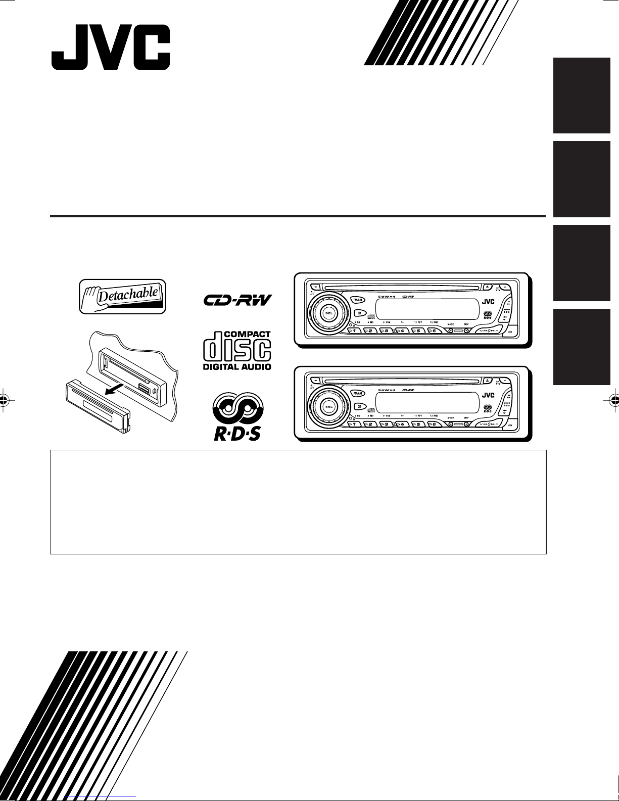
CD RECEIVER
CD-RECEIVER
RECEPTEUR CD
CD-RECEIVER
KD-G202/KD-G201
KD-G202
ENGLISH
DEUTSCH
KD-G202
KD-G201
KD-G201
• This unit is equipped with the display demonstration. To cancel it, see page 6.
• Dieses Gerät ist mit einer Demonstrationsfunktion für das Display ausgestattet. Auf
Seite 6 wird beschrieben, wie Sie diese Demonstrationsfunktion deaktivieren können.
• Cet appareil est équipé d’une fonction de démonstration des affichages. Pour l’annuler,
référez-vous à la page 6.
• Dit toestel heeft een display-demonstratiefunctie. Zie bladzijde 6 voor het annuleren van
deze functie.
For installation and connections, refer to the separate manual.
Für den Einbau und die Anschlüsse siehe das eigenständige Handbuch.
Pour l’installation et les raccordements, se référer au manuel séparé.
Bijzonderheden over de installatie en aansluiting van het apparaat vindt u in de
desbetreffende handleiding.
FRANÇAIS
NEDERLANDS
INSTRUCTIONS
BEDIENUNGSANLEITUNG
MANUEL D’INSTRUCTIONS
GEBRUIKSAANWIJZING
GET0184-001A
[E/EX]
Page 2
IMPORTANT FOR LASER PRODUCTS
1. CLASS 1 LASER PRODUCT
2. CAUTION: Do not open the top cover. There are no user serviceable parts inside the unit; leave all
servicing to qualified service personnel.
ENGLISH
3. CAUTION: Visible and invisible laser radiation when open and interlock failed or defeated. Avoid
direct exposure to beam.
4. REPRODUCTION OF LABEL: CAUTION LABEL, PLACED OUTSIDE THE UNIT.
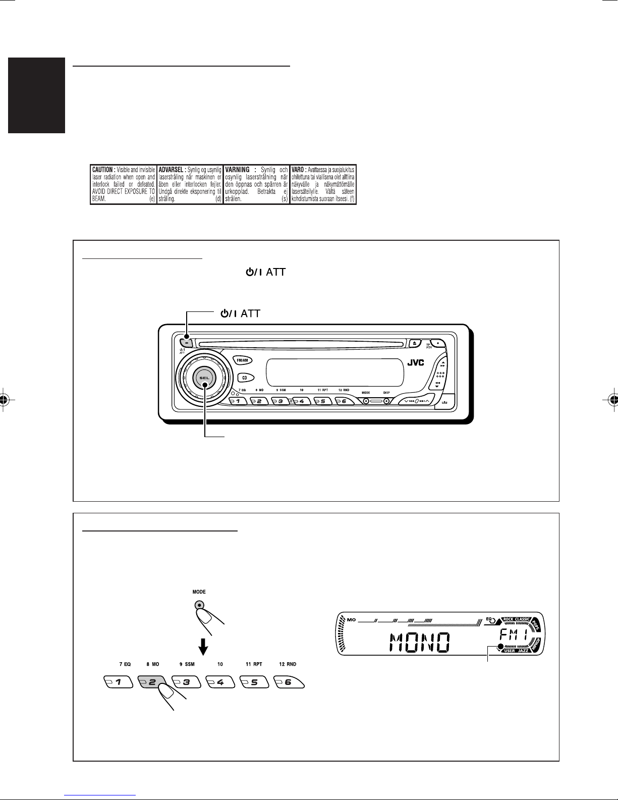
How to reset your unit
While holding SEL (select), press (standby/on attenuator) for more than 2 seconds.
This will reset the built-in microcomputer.
(standby/on attenuator)
SEL (select)
Notes:
• Your preset adjustments—such as preset channels or sound adjustments—will also be erased.
• If a CD is in the unit, it will eject when you reset the unit. Be careful not to drop the CD.
How to use the MODE button
If you press MODE, the unit goes into functions mode, then the number buttons work as different
function buttons.
Ex.: When number button 2 works as MO (monaural) button.
Time countdown indicator
To use these buttons for original functions again after pressing MODE, wait for 5 seconds
without pressing any of these buttons until the functions mode is cleared.
• Pressing MODE again also clears the functions mode.
2
Page 3
Thank you for purchasing a JVC product. Please read all instructions carefully before operation,
to ensure your complete understanding and to obtain the best possible performance from the unit.
CONTENTS
How to reset your unit ............................... 2
How to use the MODE button ................... 2
LOCATION OF THE BUTTONS ............ 4
Control panel ............................................. 4
BASIC OPERATIONS ....................... 5
Turning on the power ................................ 5
Canceling the display demonstration ........ 6
Setting the clock ........................................ 7
RADIO OPERATIONS ...................... 8
Listening to the radio ................................. 8
Storing stations in memory ....................... 10
Tuning in to a preset station ...................... 11
RDS OPERATIONS ......................... 12
What you can do with RDS ....................... 12
Other convenient RDS functions and
adjustments ............................................ 17
CD OPERATIONS ........................... 19
Playing a CD ............................................. 19
Locating a track or a particular portion
on a CD .................................................. 20
Selecting CD playback modes .................. 20
Prohibiting CD ejection ............................. 21
SOUND ADJUSTMENTS ................... 22
Selecting preset sound modes
(C-EQ: custom equalizer) ....................... 22
Adjusting the sound .................................. 23
OTHER MAIN FUNCTIONS ................ 24
Changing the general settings (PSM) ....... 24
Detaching the control panel ...................... 26
TROUBLESHOOTING ...................... 27
MAINTENANCE ............................. 28
Handling discs ........................................... 28
ENGLISH
SPECIFICATIONS ........................... 29
KD-G202 and KD-G201 are equipped with the steering wheel remote control function.
If your car is equipped with the steering wheel remote controller, you can operate the unit using the
controller.
• See the Installation/Connection Manual (separate volume) for connection to utilize this function.
Note:
For security reasons, a numbered ID card is provided with this unit, and the same ID number is imprinted on
the unit’s chassis. Keep the card in a safe place, as it will help the authorities to identify your unit if stolen.
BEFORE USE
*
For safety....
• Do not raise the volume level too much, as this will
block outside sounds, making driving dangerous.
• Stop the car before performing any complicated
operations.
*
Temperature inside the car....
If you have parked the car for a long time in hot or
cold weather, wait until the temperature in the car
becomes normal before operating the unit.
3
Page 4
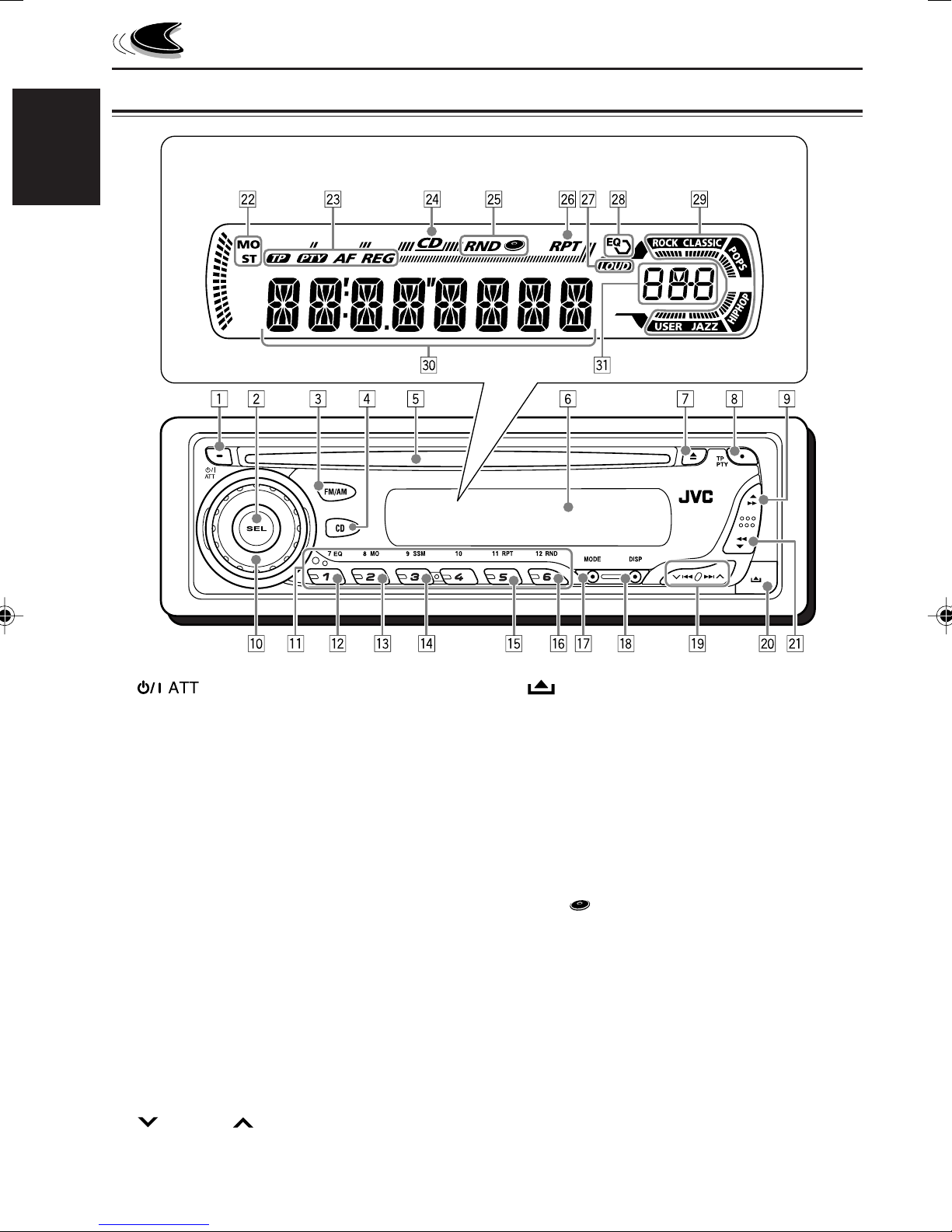
Control panel
Display window
ENGLISH
LOCATION OF THE BUTTONS
1 (standby/on attenuator) button
2 SEL (select) button
3 FM/AM button
4 CD button
5 Loading slot
6 Display window
7 0 (eject) button
8 TP PTY (traffic programme/programme type)
button
9 5 (up) button
¡ (fast-forward) button
p Control dial
q Number buttons
w EQ (equalizer) button
e MO (monaural) button
r SSM (Strong-station Sequential Memory)
button
t RPT (repeat) button
y RND (random) button
u MODE button
i DISP (display) button
o 4/¢ buttons
; (control panel release) button
a ∞ (down) button
1 (reverse) button
Display window
s Tuner reception indicators
MO (monaural), ST (stereo)
d RDS indicators
TP, PTY, AF, REG
f CD indicator
g RND (random disc) indicator
h RPT (repeat) indicator
j LOUD (loudness) indicator
k EQ (equalizer) indicator
l Sound mode (C-EQ: custom equalizer)
indicators
ROCK, CLASSIC, POPS, HIP HOP, JAZZ,
USER
/ Main display
z Source display
Volume level indicator
4
Page 5
BASIC OPERATIONS
ENGLISH
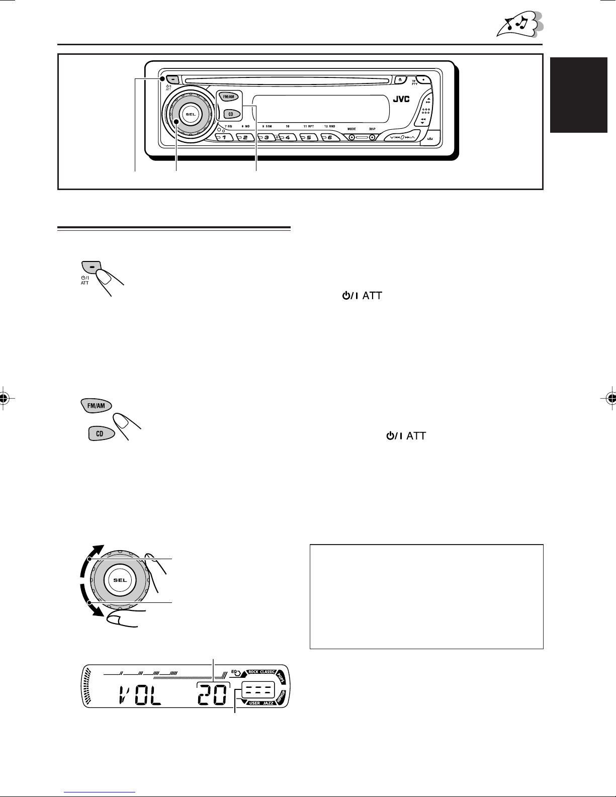
1
3
Turning on the power
1
Turn on the power.
Note on One-Touch Operation:
When you select a source in step 2 below, the
power automatically comes on. You do not have
to press this button to turn on the power.
2
Select the source.
To operate the tuner (FM or AM),
see pages 8 – 18.
To play a CD,
see pages 19 – 21.
3
Adjust the volume.
2
4
Adjust the sound as you want.
(See pages 22 and 23.)
To drop the volume in a moment
Press briefly while listening to any
source. “ATT ” starts flashing on the display, and
the volume level will drop in a moment.
To resume the previous volume level, press the
button briefly again.
• If you turn the control dial, you can also restore
the sound.
To turn off the power
Press and hold for more than one
second.
“SEE YOU” appears, then the unit turns off.
• If you turn off the power while listening to a
CD, CD play will start from where playback has
been stopped previously, next time you turn on
the power.
To increase the volume
To decrease the volume
Volume level appears.
Volume level indicator
CAUTION on Volume Setting:
CDs produce very little noise compared with other
sources. If the volume level is adjusted for the
tuner, for example, the speakers may be damaged
by the sudden increase in the output level.
Therefore, lower the volume before playing a CD
and adjust it as required during playback.
5
Page 6
ENGLISH
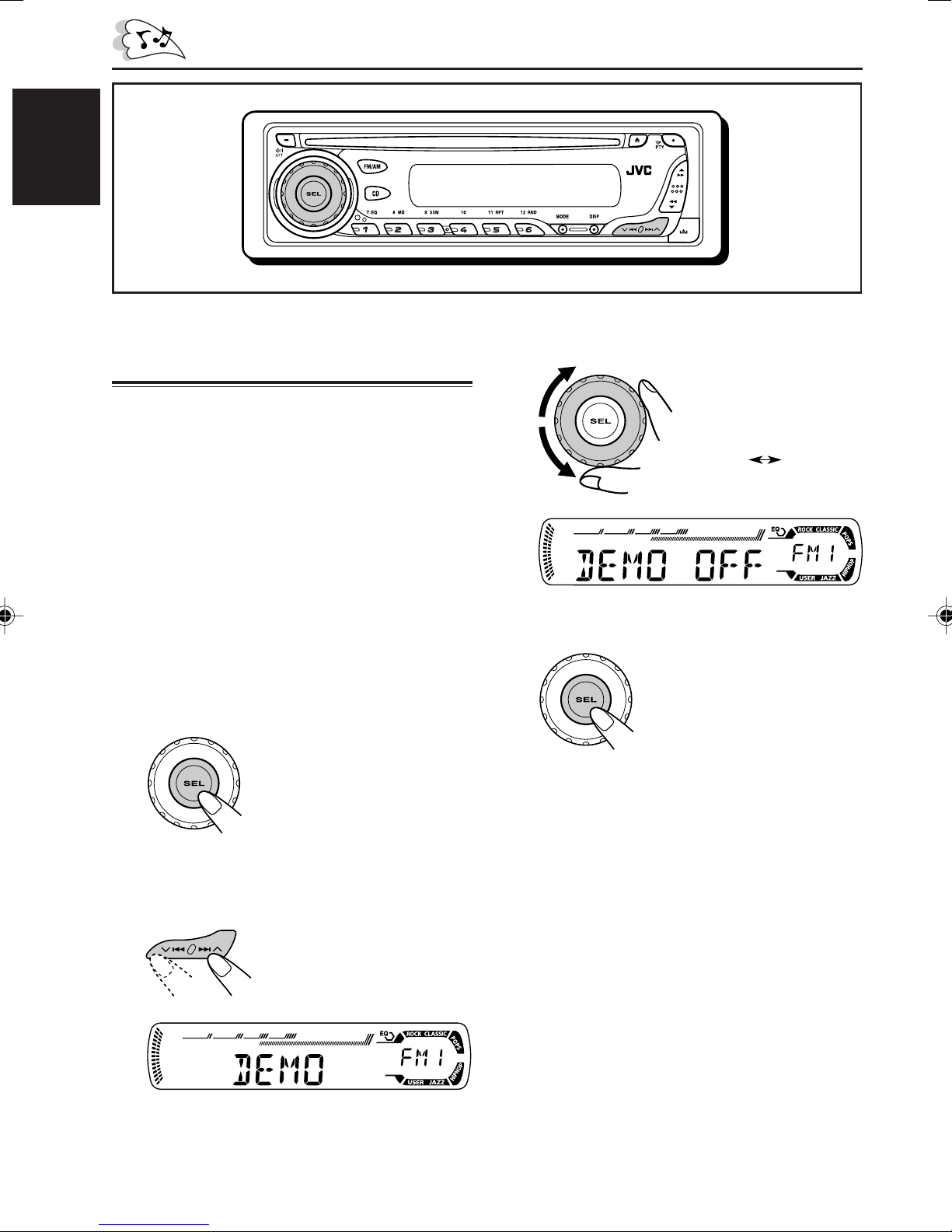
Canceling the display
demonstration
When shipped from the factory, display
demonstration has been activated, and starts
automatically when no operations are done for
about 20 seconds.
• It is recommended to cancel the display
demonstration before you use the unit for the
first time.
To cancel the display demonstration, follow
the procedure below:
1
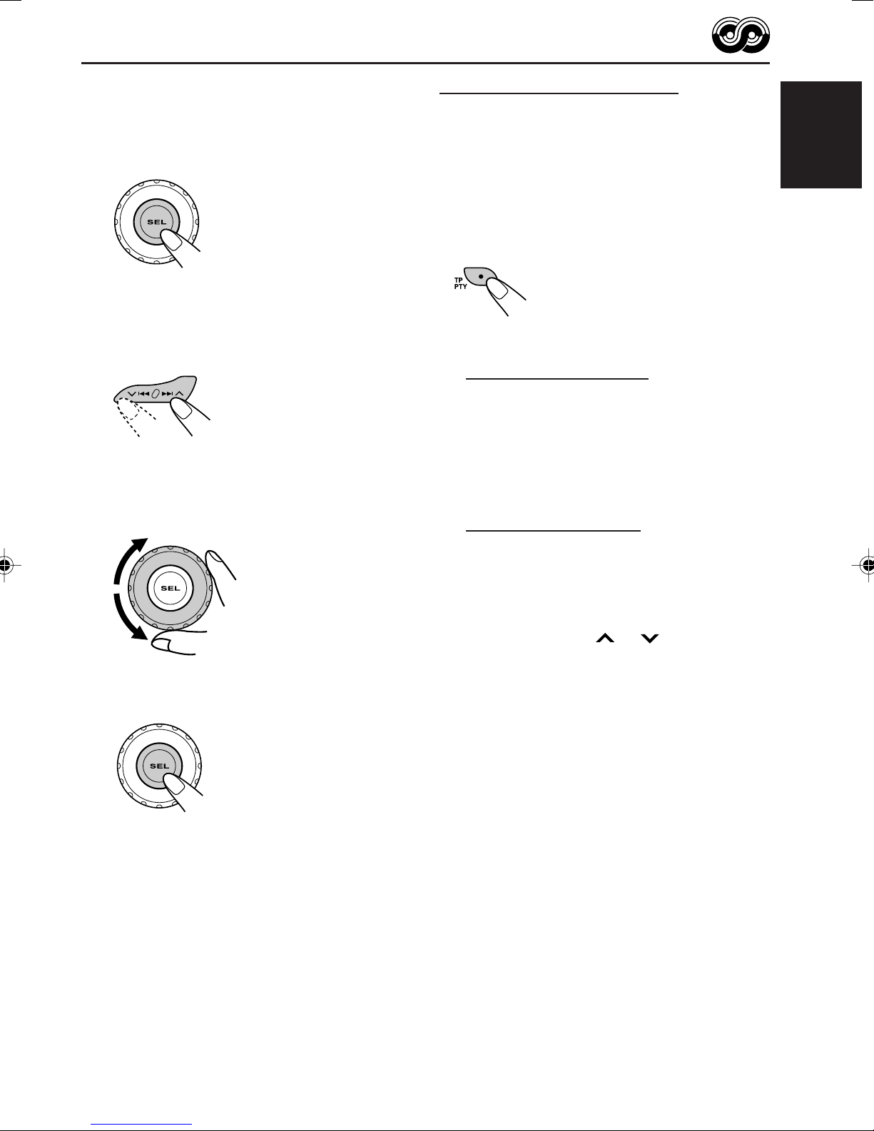
Press and hold SEL (select) for more
than 2 seconds so that one of the
PSM items appears on the display.
(PSM: see pages 24 and 25.)
3
Select “DEMO OFF.”
4
Finish the setting.
DEMO OFF
DEMO ON
2
Select “DEMO” if not shown on the
display.
6
To activate the display demonstration, repeat
the same procedure and select “DEMO ON” in
step 3.
Page 7
ENGLISH
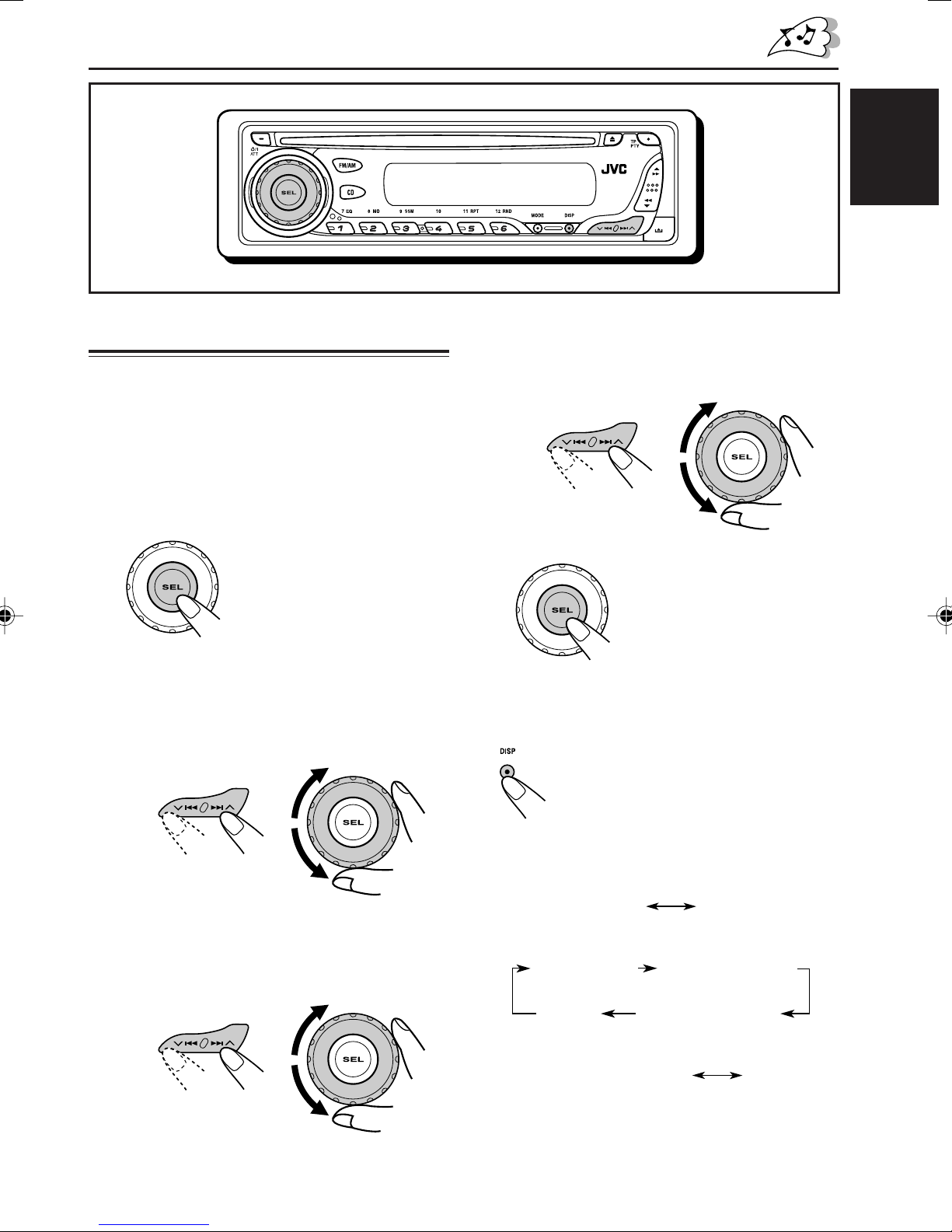
Setting the clock
You can also set the clock system to either
24 hours or 12 hours.
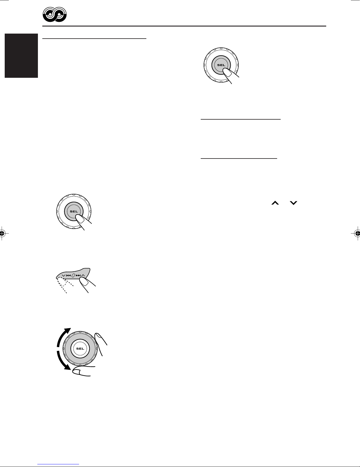
1
Press and hold SEL (select) for more
than 2 seconds so that one of the
PSM items appears on the display.
(PSM: see pages 24 and 25.)
2
Set the hour.
1 Select “CLOCK H” (hour) if not shown on
the display.
2 Adjust the hour.
12
4
Set the clock system.
1 Select “24H/12H.”
2 Select “24H” or “12H.”
12
5
Finish the setting.
To check the current clock time or change the
display mode
Press DISP (display) repeatedly.
Each time you press the button, the
display changes as follows:
3
Set the minute.
1 Select “CLOCK M” (minute).
2 Adjust the minute.
12
• During AM and FM non-RDS station
operation:
Frequency
• During FM RDS Station operation:
Station name
Programme typeClock
• During CD operation:
• During power off:
The power turns on and the clock time is
shown for 5 seconds, then the power turns off.
Clock
Station frequency
ClockElapsed playing time
7
Page 8
ENGLISH
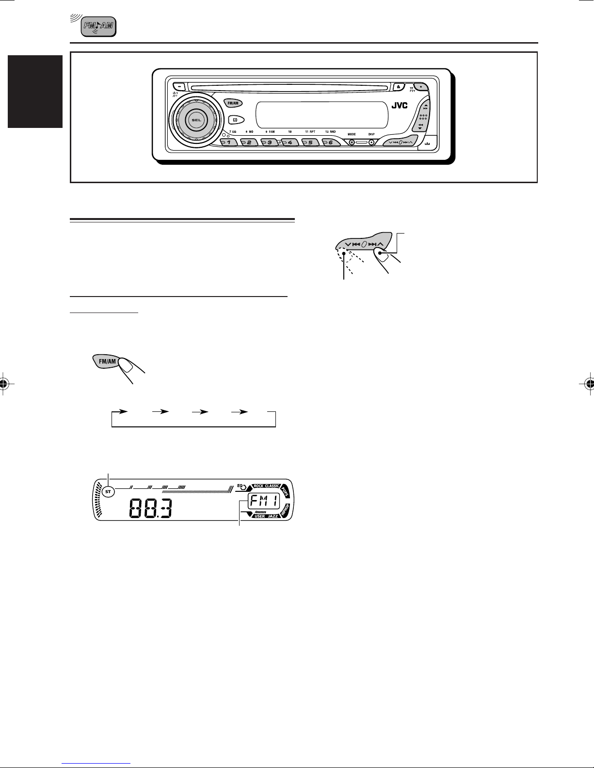
RADIO OPERATIONS
Listening to the radio
You can use either automatic searching or manual
searching to tune in to a particular station.
Searching for a station automatically:
Auto search
1
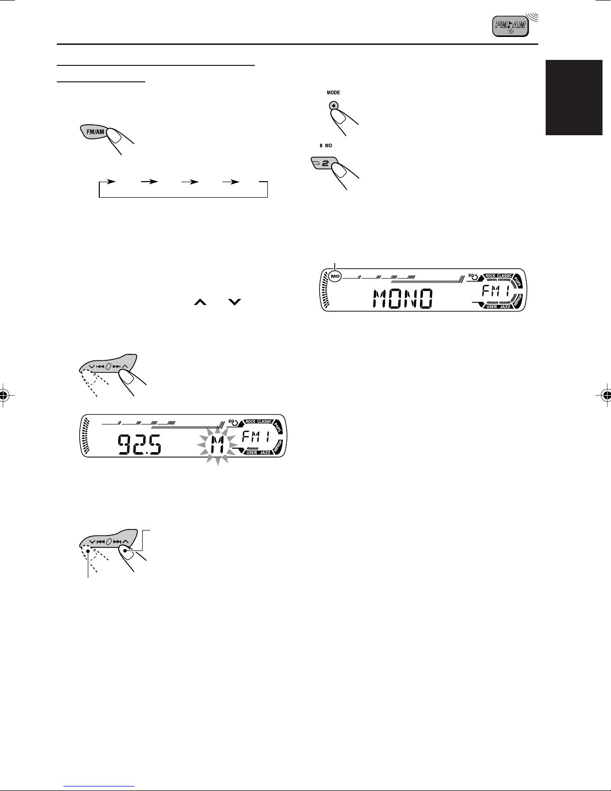
Select the band (FM1 – 3, AM).
Each time you press the
button, the band changes as
follows:
FM1 FM2 FM3 AM
Lights up when receiving an FM stereo
broadcast with sufficient signal strength.
2
Start searching for a station.
To search for stations of
higher frequencies
To search for stations of lower frequencies
When a station is received, searching stops.
To stop searching before a station is
received, press the same button you have
pressed for searching.
Selected band appears.
Note:
This receiver has three FM bands (FM1, FM2,
FM3). You can use any one of them to listen to
an FM broadcast.
8
Page 9
Searching for a station manually:
Manual search
1
Select the band (FM1 – 3, AM).
Each time you press the
button, the band changes as
follows:
FM1 FM2 FM3 AM
Note:
This receiver has three FM bands (FM1, FM2,
FM3). You can use any one of them to listen to
an FM broadcast.
2
Press and hold ¢ or 4
until “M” (manual) starts flashing on
the display.
When an FM stereo broadcast is hard to
receive
1 Press MODE to enter the
functions mode while listening
to an FM stereo broadcast.
2 Press MO (monaural), while
“MODE” is still flashing on the
display, so that “MONO”
appears on the display.
Each time you press the button,
monaural mode turns on and off
alternately.
MO (monaural) indicator
When the MO indicator is lit on the display, the
sound you hear becomes monaural but the
reception will be improved.
ENGLISH
3
Tune in to a station you want while
“M” (manual) is still flashing.
To tune in to stations of
higher frequencies
To tune in to stations of lower frequencies
• If you release your finger from the button,
the manual mode will automatically turns
off after 5 seconds.
• If you hold down the button, the frequency
keeps changing (in 50 kHz intervals for
FM and 9 kHz for AM—MW/LW) until you
release the button.
9
Page 10
Storing stations in memory
You can use one of the following two methods to
store broadcasting stations in memory.
• Automatic preset of FM stations: SSM (Strong-
ENGLISH
station Sequential Memory)
• Manual preset of both FM and AM stations
Local FM stations with the strongest signals are
searched and stored automatically in the band
number you have selected (FM1, FM2, or FM3).
These stations are preset in the number
buttons—No.1 (lowest frequency) to No.6
(highest frequency).
When automatic preset is over, the station stored
in number button 1 will be automatically tuned in.
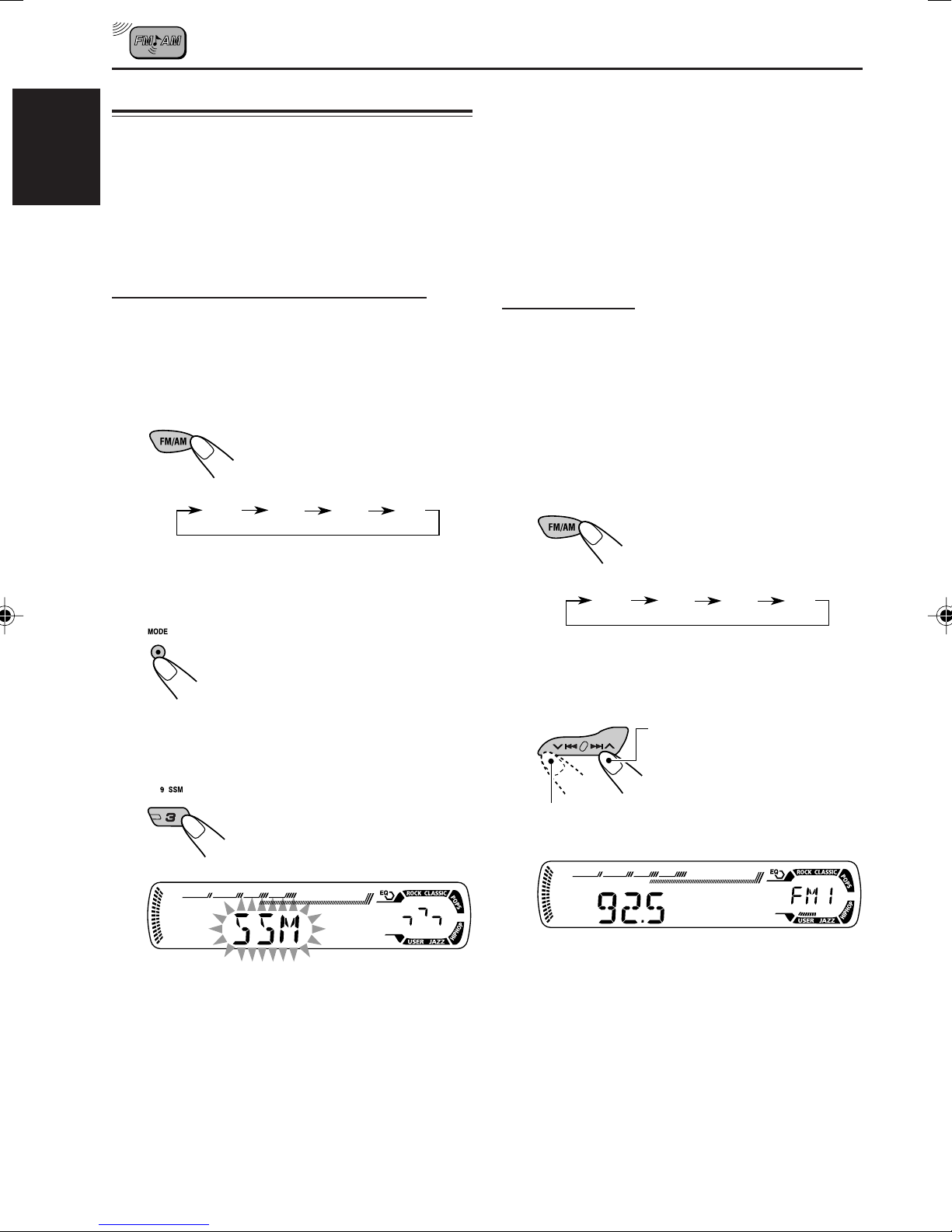
FM station automatic preset: SSM
You can preset 6 local FM stations in each FM
band (FM1, FM2, and FM3).
1
Select the FM band (FM1 – 3) you
want to store FM stations into.
Each time you press the
button, the band changes as
follows:
FM1 FM2 FM3 AM
2
Press MODE to enter the functions
mode.
3
Press and hold SSM for about
2 seconds.
Manual preset
You can preset up to 6 stations in each band
(FM1, FM2, FM3, and AM) manually.
Ex.: Storing FM station of 92.5 MHz into the
preset number 1 of the FM1 band.
1
Select the band (FM1 – 3, AM) you
want to store stations into (in this
example, FM1).
Each time you press the
button, the band changes as
follows:
FM1 FM2 FM3 AM
2
Tune in to a station (in this example,
of 92.5 MHz).
To tune in to stations of
higher frequencies
“SSM” flashes, then disappears when
automatic preset is over.
10
To tune in to stations of lower frequencies
Page 11
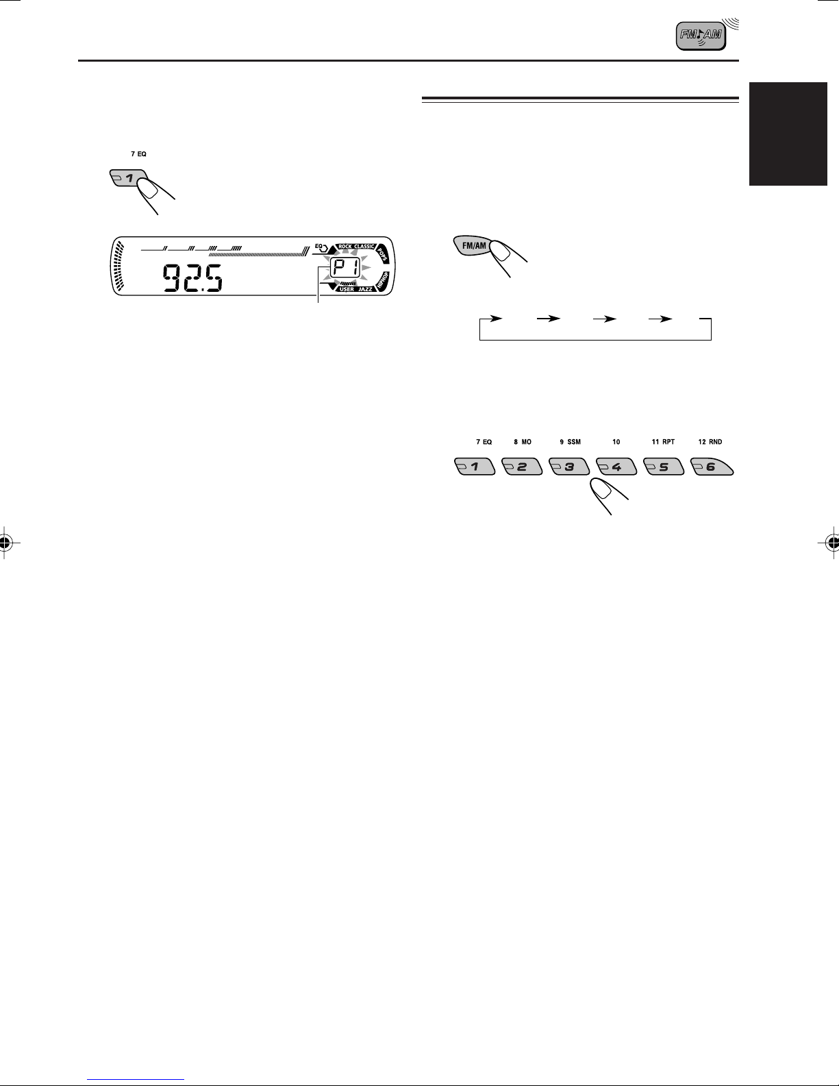
3
Press and hold the number button
(in this example, 1) for more than
2 seconds.
Tuning in to a preset station
You can easily tune in to a preset station.
Remember that you must store stations first. If
you have not stored them yet, see “Storing
stations in memory” on pages 10 and 11.
1
Select the band (FM1 – 3, AM).
Each time you press the
button, the band changes as
follows:
ENGLISH
Preset number flashes for a while.
4
Repeat the above procedure to store
other stations into other preset
numbers.
Notes:
• A previously preset station is erased when a new
station is stored in the same preset number.
• Preset stations are erased when the power supply to
the memory circuit is interrupted (for example,
during battery replacement). If this occurs, preset
the stations again.
FM1 FM2 FM3 AM
2
Select the number (1 – 6) for the
preset station you want.
Note:
You can also use the 5 (up) or ∞ (down) button on
the unit to select the next or previous preset stations.
Each time you press the 5 (up) or ∞ (down) button,
the next or previous preset station is tuned in.
11
Page 12
RDS OPERATIONS
What you can do with RDS
RDS (Radio Data System) allows FM stations to
send an additional signal along with their regular
programme signals. For example, the stations
ENGLISH
send their station names, as well as information
about what type of programme they broadcast,
such as sports or music, etc.
Another advantage of RDS function is called
“Enhanced Other Networks.” By using the
Enhanced Other Networks data sent from a
station, you can tune in to a different station of a
different network broadcasting your favorite
programme or traffic announcement while
listening to another programme or to another
source such as CD.
By receiving the RDS data, this unit can do the
following:
• Tracing the same programme automatically
(Network-Tracking Reception)
• Standby Reception of TA (Traffic
Announcement) or your favorite programme
• PTY (Programme Type) search
• Programme search
• And some other functions
Tracing the same programme
automatically (Network-Tracking
Reception)
To use Network-Tracking Reception
You can select the different modes of networktracking reception to continue listening to the
same programme in its finest reception.
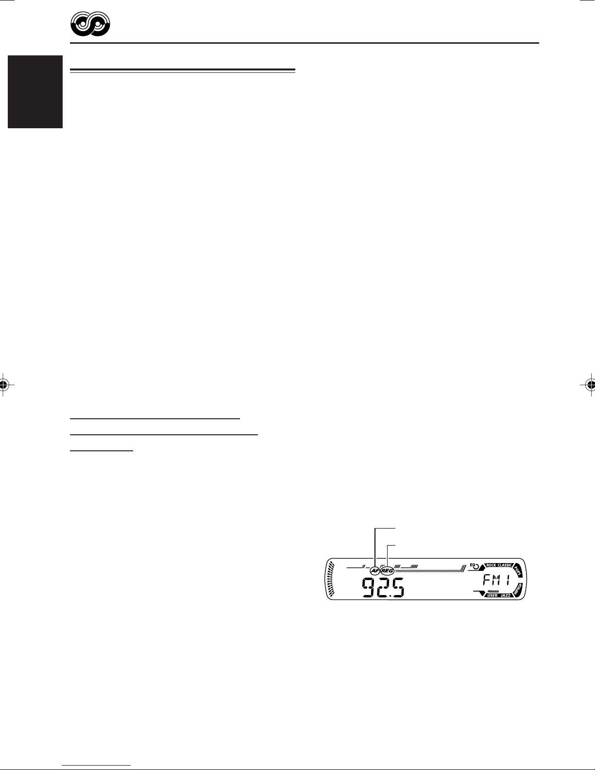
When shipped from the factory, “AF” is selected.
• AF: Network-Tracking Reception is
activated with Regionalization set to
“off.”
With this setting, the unit switches to
another station within the same
network when the received signals
from the current station become
weak. (In this mode, the programme
may differ from the one currently
received.)
The AF indicator lights up but the
REG indicator does not.
• AF REG: Network-Tracking Reception is
activated with Regionalization set to
“on.”
With this setting, the unit switches to
another station, within the same
network, broadcasting the same
programme when the received
signals from the current station
become weak.
Both the AF indicator and the REG
indicator light up.
When driving in an area where FM reception is
not good, the tuner built in this unit automatically
tunes in to another RDS station, broadcasting the
same programme with stronger signals. So, you
can continue to listen to the same programme in
its finest reception, no matter where you drive.
(See the illustration on page 18.)
Two types of the RDS data are used to make
Network-Tracking Reception work correctly
—PI (Programme Identification) and AF
(Alternative Frequency).
Without receiving these data correctly from the
RDS station you are listening to, NetworkTracking Reception will not operate.
12
• OFF: Network-Tracking Reception is
deactivated.
Neither the AF indicator nor the REG
indicator lights up.
AF indicator
REG indicator
Page 13
1
Press and hold SEL (select) for more
than 2 seconds so that one of the
PSM items appears on the display.
(PSM: see pages 24 and 25.)
2
Select “AF-REG” (alternative
frequency/regionalization reception)
if not shown on the display.
3
Select the desired mode—“AF,”
“AF REG,” or “OFF.”
4
Finish the setting.
Using TA Standby Reception
TA Standby Reception allows the unit to switch
temporarily to Traffic Announcement (TA) from
the current source (another FM station or CD).
ENGLISH
• TA Standby Reception will not work if you are
listening to an AM station.
Press TP PTY to activate TA Standby Reception.
7 When the current source is FM, the TP
indicator either lights up or flashes.
• If the TP indicator lights up, TA Standby
Reception is activated.
If a station starts broadcasting a traffic
announcement, “TRAFFIC” appears on the
display, and this unit automatically tunes in to
the station. The volume changes to the
preset TA volume level (see page 17) and the
traffic announcement can be heard.
• If the TP indicator flashes, TA Standby
Reception is not yet activated since the
station being received does not provide the
signals used for TA Standby Reception.
To activate TA Standby Reception, you need
to tune in to another station providing these
signals. Press ¢ or 4 to search
for such a station.
When a station providing these signals is
tuned in, the TP indicator stops flashing and
remains lit. Now TA Standby Reception is
activated.
7 When the current source is other than FM,
the TP indicator lights up.
If a station starts broadcasting a traffic
announcement, “TRAFFIC” appears on the
display, and this unit automatically changes the
source and tunes in to the station.
To deactivate the TA Standby Reception,
press TP PTY again. The TP indicator
disappears.
13
Page 14
Using PTY Standby Reception
PTY Standby Reception allows the unit to switch
temporarily to your favorite programme (PTY:
Programme Type) from the current source
ENGLISH
(another FM station or CD).
• PTY Standby Reception will not work if you are
listening to an AM station.
You can select your favorite programme type for
PTY Standby Reception.
When shipped from the factory, PTY Standby
Reception is turned off. (“OFF” is selected for
PTY Standby Reception.)
1
Press and hold SEL (select) for more
than 2 seconds so that one of the
PSM items appears on the display.
(PSM: see pages 24 and 25.)
2
Select “PTY STBY” (standby) if not
shown on the display.
4
Finish the setting.
7 When the current source is FM, the PTY
indicator either lights up or flashes.
• If the PTY indicator lights up, PTY Standby
Reception is activated.
If a station starts broadcasting the selected
PTY programme, this unit automatically
tunes in to the station.
• If the PTY indicator flashes, PTY Standby
Reception is not yet activated since the
station being received does not provide the
signals used for PTY Standby Reception.
To activate PTY Standby Reception, you
need to tune in to another station providing
these signals. Press ¢ or 4 to
search for such a station.
When a station providing these signals is
tuned in, the PTY indicator stops flashing
and remains lit. Now PTY Standby Reception
is activated.
7 When the current source is other than FM,
the PTY indicator lights up.
If a station starts broadcasting the selected
PTY programme, this unit automatically
changes the source and tunes in to the station.
3
Select one of the twenty-nine PTY
codes. (See page 18.)
Selected code name
appears on the display
and is stored into
memory.
14
To deactivate the PTY Standby Reception,
select “OFF” in step 3 on the left column. The
PTY indicator disappears.
Page 15
Searching your favorite programme
You can search any one of the PTY codes.
In addition, you can store your 6 favorite
programme types in the number buttons.
When shipped from the factory, the following
6 programme types have been stored in the
number buttons (1 to 6).
To store your favorite programme types, see
below.
To search your favorite programme type, see
page 16.
3
Press and hold the number button
for more than 2 seconds to store the
PTY code selected into the preset
number you want.
ENGLISH
1
POP M
45
CLASSICS
2
ROCK M EASY M
AFFAIRS
3
6
VARIED
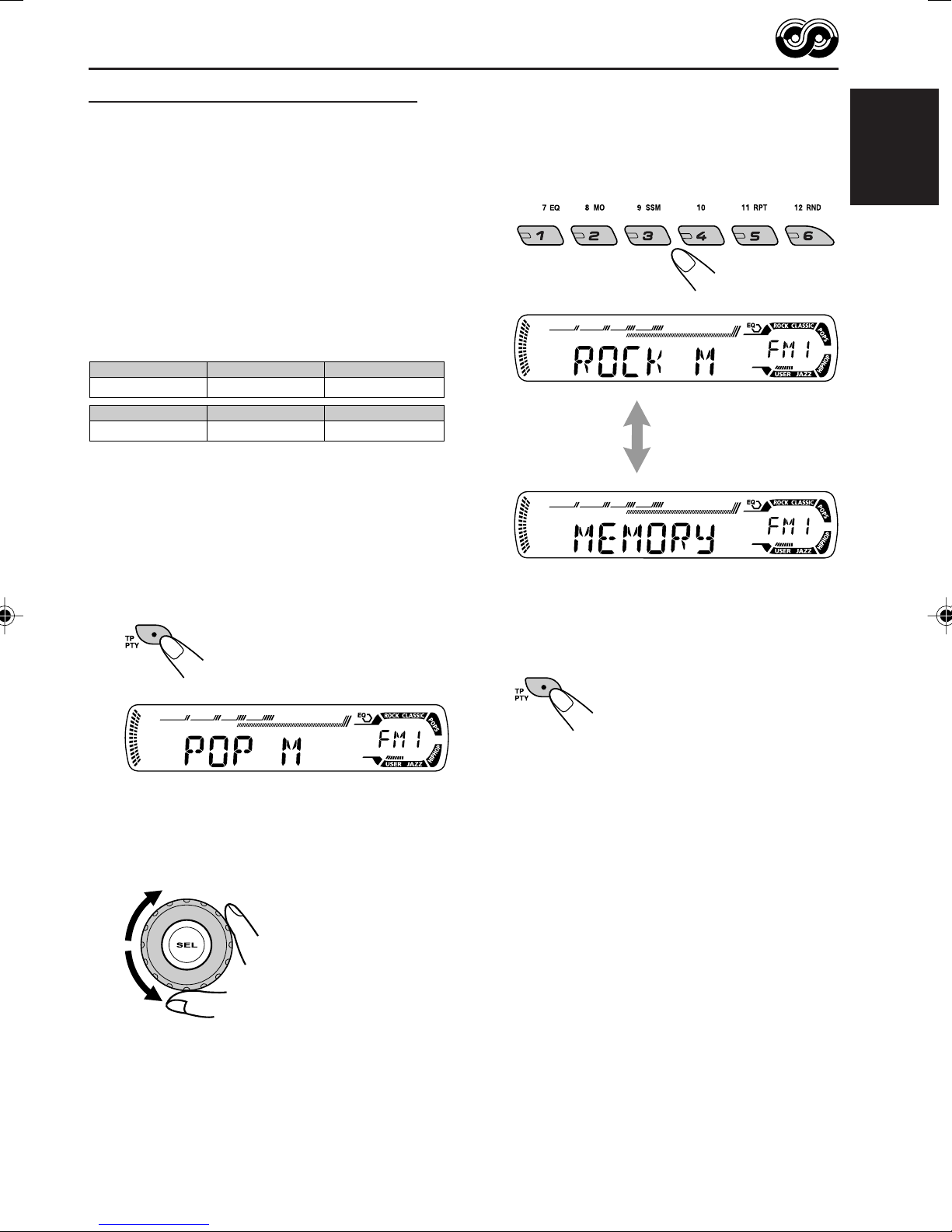
To store your favorite programme types
1
Press and hold TP PTY for more
than 2 seconds while listening to an
FM station.
The last selected PTY code appears.
Selected PTY code and
“MEMORY” appear
alternately for a while.
4
Press and hold TP PTY for more
than 2 seconds to exit from this
mode.
2
Select one of the twenty-nine PTY
codes. (See page 18.)
Selected code name
appears on the display.
15
Page 16
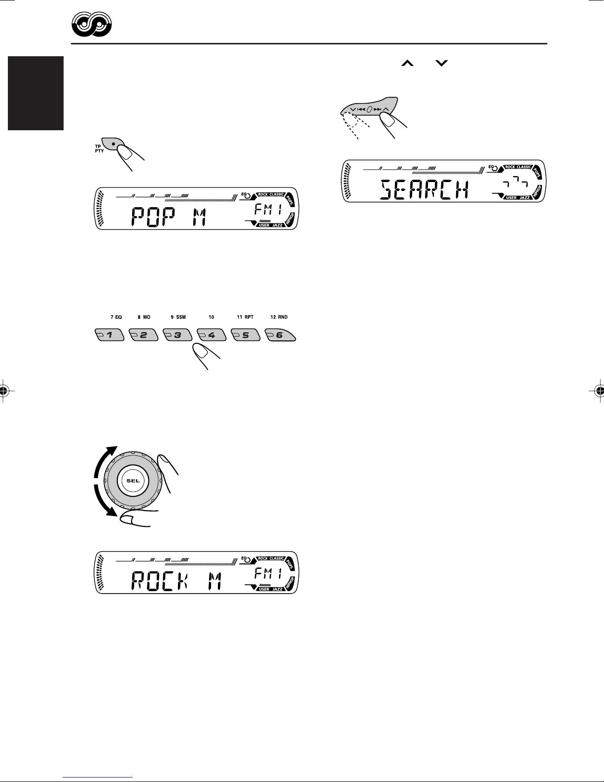
To search your favorite programme type
1
Press and hold TP PTY for more
than 2 seconds while listening to an
ENGLISH
FM station.
3
Press ¢ or 4 to start PTY
search for your favorite programme.
The last selected PTY code appears.
2
To select one of your favorite
programme type
or
To select any one of the twenty-nine
PTY codes.
• If there is a station broadcasting a programme
of the same PTY code as you selected, that
station is tuned in.
• If there is no station broadcasting a
programme of the same PTY code as you
selected, the station will not change.
Note:
In some areas, the PTY search will not work correctly.
Ex.: When “ROCK M” is selected
16
Page 17
Other convenient RDS
Setting the TA volume level
functions and adjustments
Automatic selection of the station
when using the number buttons
Usually when you press the number button, the
preset station is tuned in.
However, when the preset station is an RDS
station, something different will happen. If the
signals from that preset station are not sufficient
for good reception, this unit, using the AF data,
tunes in to another frequency broadcasting the
same programme as the original preset station is
broadcasting. (Programme search)
• The unit takes some time to tune in to another
station using programme search.
To activate programme search, follow the
procedure below.
• See also “Changing the general settings
(PSM)” on page 24.
1 Press and hold SEL (select) for more than
2 seconds so that one of the PSM items
appears on the display.
2 Press ¢ or 4 to select
“P(Programme)-SEARCH.”
3 Turn the control dial clockwise to select “ON.”
Now programme search is activated.
4 Press SEL (select) to finish the setting.
You can preset the volume level for TA Standby
Reception. When a traffic programme is received,
the volume level automatically changes to the
preset level.
• See also “Changing the general settings
(PSM)” on page 24.
1 Press and hold SEL (select) for more than
2 seconds so that one of the PSM items
appears on the display.
2 Press ¢ or 4 to select “TA VO L”
(volume).
3 Turn the control dial to set to the desired
volume.
You can set it from “VOL 00” to “VOL 30” or
“VOL 50” (depending on the amplifier gain
control setting: see page 25).
4 Press SEL (select) to finish the setting.
Automatic clock adjustment
When shipped from the factory, the clock built in
this unit is set to be readjusted automatically
using the CT (Clock Time) data in the RDS
signal.
If you do not want to use automatic clock
adjustment, follow the procedure below.
• See also “Changing the general settings
(PSM)” on page 24.
ENGLISH
To cancel programme search, repeat the same
procedure and select “OFF” in step 3 by turning
the control dial counterclockwise.
1 Press and hold SEL (select) for more than
2 seconds so that one of the PSM items
appears on the display.
2 Press ¢ or 4 to select “AUTO
ADJ” (adjustment).
3 Turn the control dial counterclockwise to select
“OFF.”
Now automatic clock adjustment is canceled.
4 Press SEL (select) to finish the setting.
To reactivate clock adjustment, repeat the
same procedure and select “ON” in step 3 by
turning the control dial clockwise.
Note:
You must stay tuned to the same station for more than
2 minutes after setting “AUTO ADJ” to “ON.”
Otherwise, the clock time will not be adjusted. (This is
because the unit takes up to 2 minutes to capture the
CT data in the RDS signal.)
17
Page 18
PTY codes
NEWS: News
AFFAIRS: Topical programmes expanding
ENGLISH
INFO: Programmes which impart
SPORT: Sport events
EDUCATE: Educational programmes
DRAMA: Radio plays
CULTURE: Programmes on national or
SCIENCE: Programmes on natural science
VARIED: Other programmes like comedies
POP M: Pop music
ROCK M: Rock music
EASY M: Easy-listening music
LIGHT M: Light music
CLASSICS: Classical music
OTHER M: Other music
WEATHER: Weather information
FINANCE: Reports on commerce, trading,
CHILDREN: Entertainment programmes for
on current news or affairs
advice on a wide variety of topics
regional culture
and technology
or ceremonies
the Stock Market, etc.
children
SOCIAL: Programmes on social
activities
RELIGION: Programmes dealing with any
aspect of belief or faith, or the
nature of existence or ethics
PHONE IN: Programmes where people can
express their views either by
phone or in a public forum
TRAVEL: Programmes about travel
destinations, package tours,
and travel ideas and
opportunities
LEISURE: Programmes concerned with
recreational activities such as
gardening, cooking, fishing,
etc.
JAZZ: Jazz music
COUNTRY: Country music
NATION M: Current popular music from
another nation or region, in that
country’s language
OLDIES: Classic pop music
FOLK M: Folk music
DOCUMENT: Programmes dealing with
factual matters, presented in an
investigative style
18
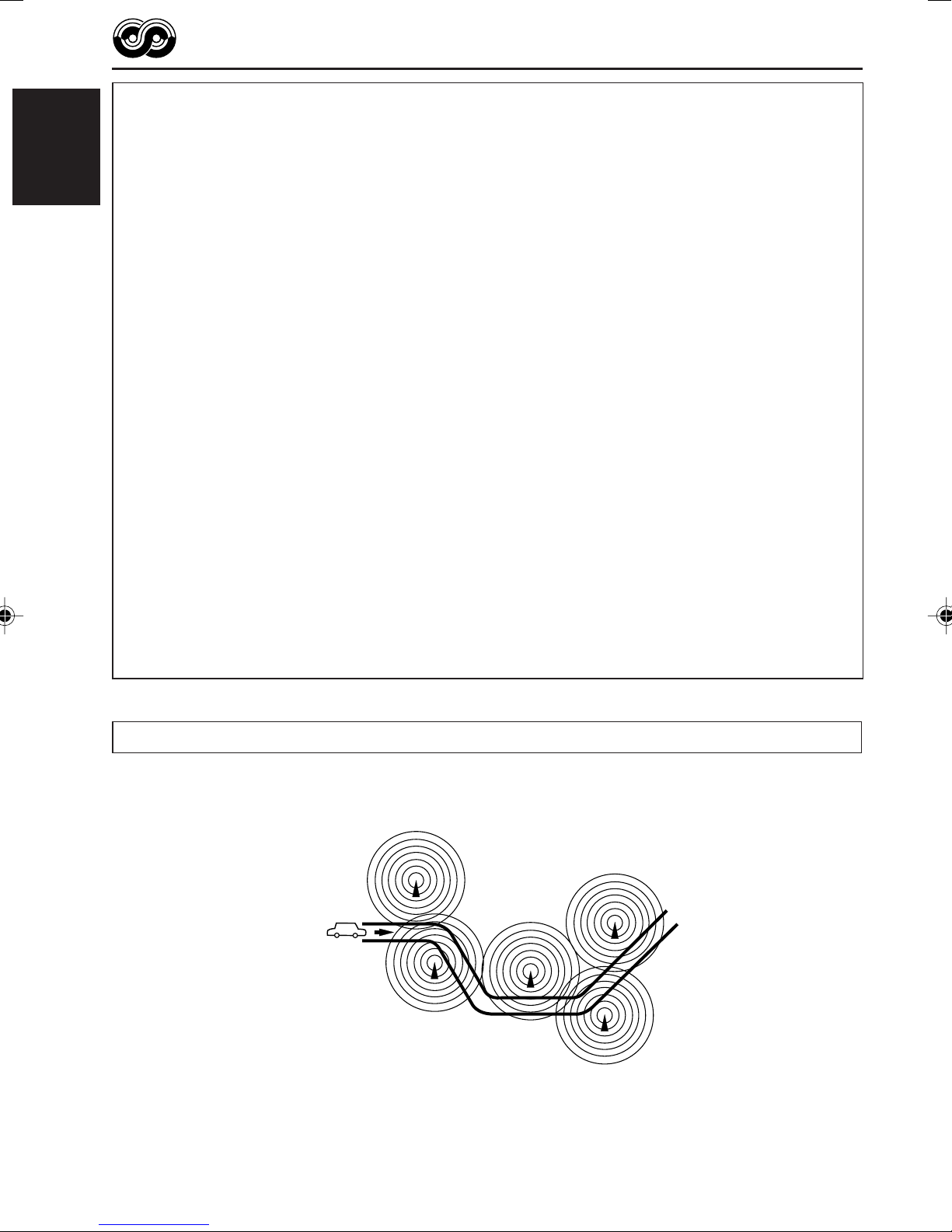
The same programme can be received on different frequencies.
Programme 1
broadcasting on
frequency A
Programme 1
broadcasting on
frequency B
Programme 1
broadcasting on
frequency C
Programme 1
broadcasting on
frequency E
Programme 1
broadcasting on
frequency D
Page 19

CD OPERATIONS
ENGLISH
Playing a CD
Insert a CD into the loading slot.
The unit turns on, draws
the CD and starts
playback automatically.
Note on One-Touch Operation:
When a CD is already in the loading slot, pressing
CD turns on the unit and starts playback
automatically.
CD indicator
Current source indication
Total playing time
of the inserted disc
Total track number
of the inserted disc
Notes:
• When a CD is inserted upside down, “EJECT”
appears on the display and the CD automatically
ejects.
• If there is no CD in the loading slot, you cannot
select CD as the source. “NO DISC” appears on
the display.
To stop play and eject the CD
Press 0.
CD play stops and the CD automatically ejects
from the loading slot. The source changes to the
tuner (you will hear the last received station).
• If you change the source, CD play also stops
(without ejecting the CD).
Next time you select “CD” as the source, CD
play starts from where playback has been
stopped previously.
Notes:
• If the ejected CD is not removed for about 15 seconds,
the CD is automatically inserted again into the
loading slot to protect it from dust.
(CD play will not start this time.)
• You can eject the CD even when the unit is turned
off.
Elapsed playing time Current track
number
All tracks will be played repeatedly until you stop
playback.
About mistracking:
Mistracking may result from driving on extremely
rough roads. This does not damage the unit and
the CD, but will be annoying.
We recommend that you stop CD play while driving
on such rough roads.
19
Page 20

Locating a track or a
particular portion on a CD
To fast-forward or reverse the track
ENGLISH
Selecting CD playback modes
To play back tracks at random
(Disc Random Play)
You can play back all tracks on the CD at random.
Press and hold ¡, while
playing a CD, to fast-forward the
track.
Press and hold 1, while playing a CD, to
reverse the track.
To go to the next or previous tracks
Press ¢ briefly, while
playing a CD, to go ahead to the
beginning of the next track.
Each time you press the button
consecutively, the beginning of
the next tracks is located and
played back.
Press 4 briefly, while playing a CD, to go
back to the beginning of the current track.
Each time you press the button consecutively,
the beginning of the previous tracks is located
and played back.
1 Press MODE to enter the
functions mode while playing a
CD.
2 Press RND (random), while
“MODE” is still flashing on the
display, so that “DISC RND”
appears on the display.
Each time you press the button,
disc random play mode turns on
and off alternately.
RND (random disc) indicator
When disc random play is turned on, the
RND indicator lights up on the display. A
track randomly selected starts playing.
To go to a particular track directly
Press the number button corresponding to the
track number to start its playback.
• To select a track number from 1 – 6:
Press 1 (7) – 6 (12) briefly.
• To select a track number from 7 – 12:
Press and hold 1 (7) – 6 (12) for more than one
second.
20
Page 21

To play back tracks repeatedly
(Track Repeat Play)
You can play back the current track repeatedly.
1 Press MODE to enter the
functions mode while playing a
CD.
2 Press RPT (repeat), while
“MODE” is still flashing on the
display, so that “TRK RPT”
appears on the display.
Each time you press the button,
track repeat play mode turns on
and off alternately.
RPT indicator
When track repeat play is turned on, the RPT
indicator lights up on the display. The current
track starts playing repeatedly.
Prohibiting CD ejection
You can prohibit CD ejection and can lock a CD
in the loading slot.
ENGLISH
While pressing CD, press and hold 0 for
more than 2 seconds.
“EJECT” flashes on the display for about 5 seconds,
and the CD is locked and cannot be ejected.
To cancel the prohibition and unlock the
CD
While pressing CD, press and hold 0 again for
more than 2 seconds.
“EJECT” appears on the display, and the CD
ejects from the loading slot.
21
Page 22
SOUND ADJUSTMENTS
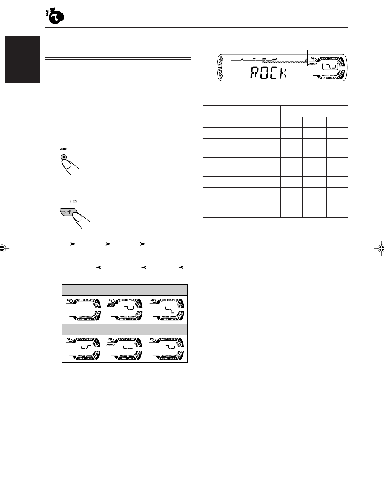
Selecting preset sound modes
(C-EQ: custom equalizer)
You can select a preset sound mode (C-EQ:
ENGLISH
custom equalizer) suitable to the music genre.
• There is a time limit in doing the following
procedure. If the setting is canceled before you
finish, start from step 1 again.
1
Press MODE to enter the functions
mode.
2
Select the sound mode you want.
Each time you press the
button, the sound modes
change as follows:
Indication pattern changes for each
sound mode except for “USER.”
Ex.: When you select “ROCK”
Indication For: Preset values
BAS TRE LOUD
USER (Flat sound) 00 00 OFF
ROCK Rock or +03 +01 ON
disco music
CLASSIC Classical +01 –02 OFF
music
POPS Light music +04 +01 OFF
HIP HOP Funk or rap +02 00 ON
music
JAZZ Jazz music +02 +03 OFF
USER
JAZZ
ROCK
HIP HOP
CLASSIC
POPSHIP HOPJAZZ
CLASSICROCKUSER
POPS
Note:
You can adjust each sound mode to your preference.
Once you make an adjustment, it is automatically
stored for the currently selected sound mode. See
“Adjusting the sound” on page 23.
22
Page 23

Adjusting the sound
You can adjust the sound characteristics to your
preference.
1
Select the item you want to adjust.
Each time you press the
button, the adjustable items
change as follows:
BAS
(bass)
VOL
(volume)
Indication To do: Range
1
BAS*
TRE*
FAD*
1
2
Adjust the bass. –06 (min.)
Adjust the treble. –06 (min.)
Adjust the front R06 (Rear only)
and rear speaker |
balance. F06 (Front only)
TRE
(treble)
LOUD
(loudness)
FAD
(fader)
BAL
(balance)
|
+06 (max.)
|
+06 (max.)
1
*
When you adjust the bass, treble, or loudness, the
adjustment you have made is stored for the
currently selected sound mode (C-EQ) including
“USER.”
2
*
If you are using a two-speaker system, set the fader
level to “00.”
3
*
Normally the control dial works as the volume
control. So you do not have to select “VOL” to
adjust the volume level.
4
*
Depending on the amplifier gain control setting.
(See page 25 for details.)
2
Adjust the setting.
To increase the level or
turn on the loudness
To decrease the level
or turn off the loudness
Indication pattern changes as
you adjust the bass or treble.
Ex. 1: When you adjust “TRE” (treble)
ENGLISH
BAL Adjust the left L06 (Left only)
and right speaker |
balance. R06 (Right only)
LOUD*
VOL*
1
Boost low and high
frequencies to LOUD ON
produce a well- |
balanced sound LOUD OFF
at low volume
level.
3
Adjust the volume. 00 (min.)
|
30 or 50 (max.)*
Ex. 2: When you turn on the loudness
3
Repeat steps 1 and 2 to adjust the
other items.
To reset each sound mode to the factory
settings, repeat the same procedure and
4
reassign the preset values listed in the table on
page 22.
23
Page 24

OTHER MAIN FUNCTIONS
Changing the general settings
(PSM)
You can change the items listed in the table
ENGLISH
below and page 25 by using the PSM (Preferred
Setting Mode) control.
Basic Procedure
1
Press and hold SEL (select) for more
than 2 seconds so that one of the
PSM items appears on the display.
(See below and page 25.)
2
Select the PSM item you want to
adjust.
3
Adjust the PSM item selected.
4
Repeat steps 2 and 3 to adjust the
other PSM items if necessary.
5
Finish the setting.
Preferred Setting Mode (PSM) items
• For detailed operations of each PSM items, refer to the pages listed in the table.
Indications Selectable values/items
DEMO Display demonstration
CLOCK H Hour adjustment
CLOCK M Minute adjustment
24H/12H 24/12-hour time display
AUTO ADJ Automatic clock setting
AF-REG Alternative frequency/
Regionalization reception
DEMO ONDEMO OFF DEMO ON 6
0 — 23 (1 — 12)
00 — 59
12H 24H
OFF ON
AF AF REG
OFF
Factory-preset See
settings page
0 (0:00)
00 (0:00)
24H
ON 17
AF
7
12, 13
24
Page 25

Indications Selectable values/items
Factory-preset See
settings page
PTY STBY PTY standby
TA VO L Traffic announcement
volume
P-SEARCH Programme search
DIMMER Dimmer mode
TEL Telephone muting
AMP GAIN Amplifier gain control
OFF
VOL 00 — VOL 30 or 50* VOL 20
LOW PWR HIGH PWR HIGH PWR 25
29 programme types
(see page 18)
OFF ON OFF
OFF MUTING 1
MUTING 2
* Depending on the amplifier gain control setting. (See below for details.)
To select the dimmer mode—DIMMER
You can dim the display at night (according to
your preference).
When shipped from the factory, dimmer is
deactivated.
• OFF: Cancels the dimmer.
• ON: Activates the dimmer.
To select the amplifier gain control
—AMP GAIN
You can change the maximum volume level of
this unit. When the maximum power of the
speakers is less than 50 W, select “LOW PWR”
to prevent them from being damaged.
When shipped from the factory, “HIGH PWR” is
selected.
OFF
OFFOFF ON 25
OFF
14
17
17
25
ENGLISH
To select the telephone muting—TEL
This mode is used when a cellular phone system
is connected. Depending on the phone system
used, select either “MUTING 1” or “MUTING 2”
whichever mutes the sounds from this unit.
When shipped from the factory, this mode is
deactivated.
• MUTING 1: Select if this setting can mute the
sounds.
• MUTING 2: Select if this setting can mute the
sounds.
• OFF: Cancels the telephone muting.
• LOW PWR: You can adjust the volume level
from “VOL 00” to “VOL 30.”
Note:
If you change the setting from
“HIGH PWR” to “LOW PWR” while
listening at a volume level more than
30, the unit automatically changes the
volume level to “VOL 30.”
• HIGH PWR: You can adjust the volume level
from “VOL 00” to “VOL 50.”
25
Page 26
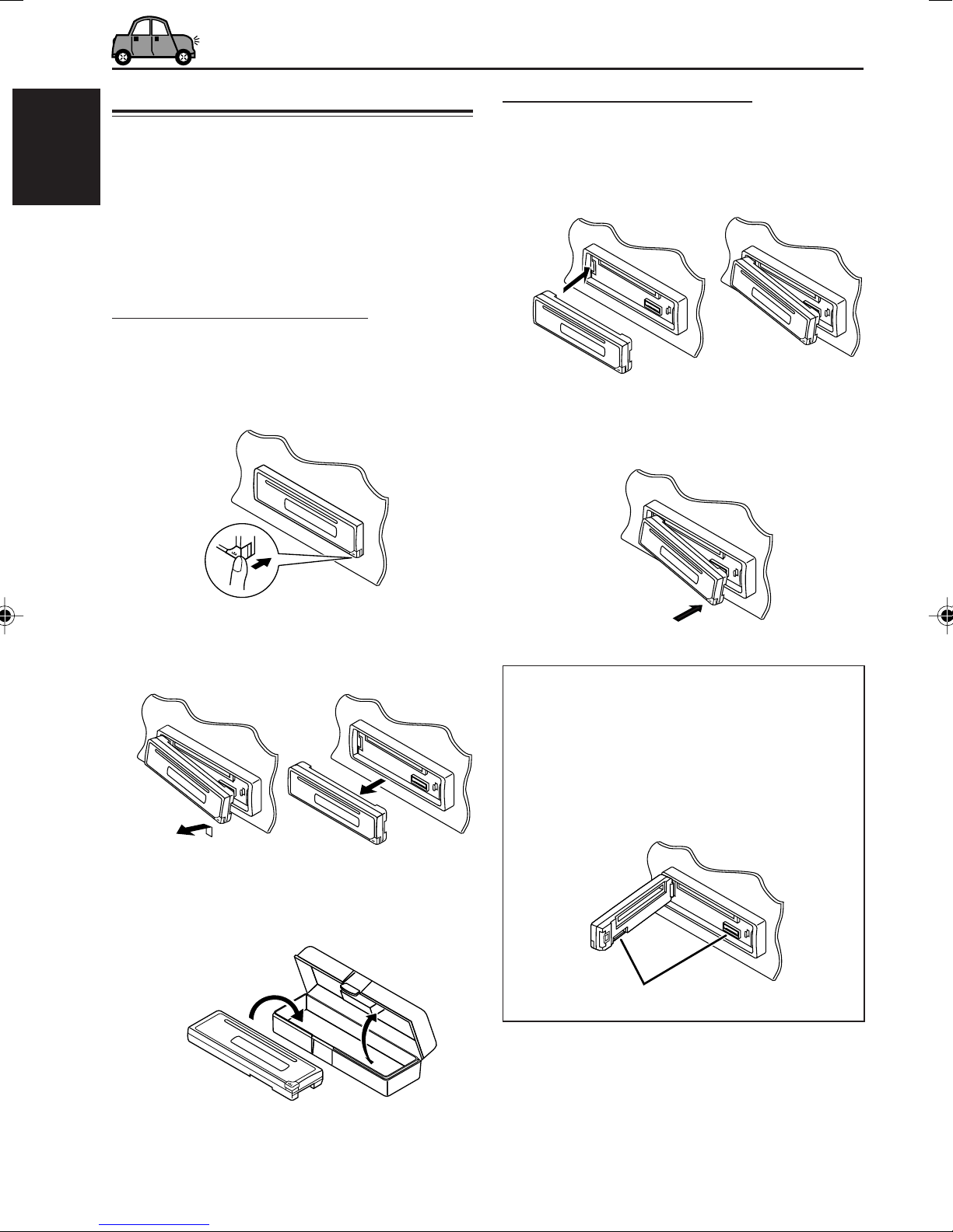
Detaching the control panel
You can detach the control panel when leaving
the car.
When detaching or attaching the control panel,
ENGLISH
be careful not to damage the connectors on the
back of the control panel and on the panel
holder.
Detaching the control panel
Before detaching the control panel, be sure to
turn off the power.
1
Unlock the control panel.
Attaching the control panel
1
Insert the left side of the control
panel into the groove on the panel
holder.
2
Press the right side of the control
panel to fix it to the panel holder.
2
Lift and pull the control panel out of
the unit.
3
Put the detached control panel into
the provided case.
Note on cleaning the connectors:
If you frequently detach the control panel, the
connectors will deteriorate.
To minimize this possibility, periodically wipe the
connectors with a cotton swab or cloth moistened
with alcohol, being careful not to damage the
connectors.
Connectors
26
Page 27

TROUBLESHOOTING
What appears to be trouble is not always serious. Check the following points before calling a service
center.
Symptoms
• Sound cannot be heard
from the speakers.
• This unit does not work at
all.
General
• SSM (Strong-station
Sequential Memory)
automatic preset does not
work.
FM/AM
• Static noise while listening
to the radio.
• CD automatically ejects.
Causes
The volume level is set to the
minimum level.
Connections are incorrect.
The built-in microcomputer
may have functioned
incorrectly due to noise, etc.
Signals are too weak.
The aerial is not connected
firmly.
CD is inserted upside down.
Remedies
Adjust it to the optimum level.
Check the cords and
connections.
While holding SEL (select),
press (standby/on
attenuator) for more than
2 seconds to reset the unit. (The
clock setting and preset stations
stored in memory are erased.)
(See page 2.)
Store stations manually.
Connect the aerial firmly.
Insert the CD correctly.
ENGLISH
• CD-R/CD-RW cannot be
played back.
• Tracks on the CD-R/CD-RW
cannot be skipped.
• CD can be neither played
back nor ejected.
CD Playback
• CD sound is sometimes
interrupted.
•“NO DISC” appears on the
display.
CD-R/CD-RW is not finalized.
CD is locked.
The CD player may have
functioned incorrectly.
You are driving on rough
roads.
CD is scratched.
Connections are incorrect.
No CD in the loading slot.
CD is inserted incorrectly.
• Insert a finalized CD-R/
CD-RW.
• Finalize the CD-R/CD-RW
with the component which
you used for recording.
Unlock the CD.
(See page 21.)
While holding
(standby/on attenuator), press
0 (eject) for more than
2 seconds. Be careful not to
drop the CD when it is ejected.
Stop playback while driving on
rough roads.
Change the CD.
Check the cords and
connections.
Insert a CD into the loading slot.
Insert the CD correctly.
27
Page 28

MAINTENANCE
Handling discs
This unit has been designed to reproduce CDs,
CD-Rs (Recordable), and CD-RWs (Rewritable).
• This unit is not compatible with MP3 discs.
ENGLISH
How to handle discs
When removing a disc
from its case, press down
the center holder of the case
and lift the disc out, holding
it by the edges.
• Always hold the disc by the edges. Do not
touch its recording surface.
When storing a disc into its case, gently insert
the disc around the center holder (with the
printed surface facing up).
• Make sure to store discs into the cases after
use.
To keep discs clean
A dirty disc may not be played
correctly. If a disc does become
dirty, wipe it with a soft cloth in a
straight line from center to edge.
To play new discs
New discs may have some rough
spots around the inner and outer
edges. If such a disc is used, this
unit may reject the disc.
To remove these rough spots, rub the edges with
a pencil or ball-point pen, etc.
Moisture condensation
Moisture may condense on the lens inside the
CD player in the following cases:
• After starting the heater in the car.
• If it becomes very humid inside the car.
Should this occur, the CD player may
malfunction. In this case, eject the disc and leave
the unit turned on for a few hours until the
moisture evaporates.
Center holder
When playing a CD-R or CD-RW
Before playing back CD-Rs or CD-RWs, read
their instructions or cautions carefully.
• Use only “finalized” CD-Rs or CD-RWs.
• Some CD-Rs or CD-RWs may not be played
back on this unit because of their disc
characteristics, and for the following reasons:
– Discs are dirty or scratched.
– Moisture condensation on the lens inside the
unit.
– The pickup lens inside the unit is dirty.
• CD-RWs may require a longer readout time
since the reflectance of CD-RWs is lower than
that of regular CDs.
• CD-Rs or CD-RWs are susceptible to high
temperatures or high humidity, so do not leave
them inside your car.
• Do not use following CD-Rs or CD-RWs:
– Discs with stickers, labels, or protective seal
stuck to the surface.
– Discs on which labels can be directly printed
by an ink jet printer.
Using these discs under high temperatures or
high humidity may cause malfunctions or
damage to discs. For example,
– Stickers or labels may shrink and warp a
disc.
– Stickers or labels may be peeled off so discs
cannot be ejected.
– Print on discs may get sticky.
Read instructions or cautions about labels and
printable discs carefully.
CAUTIONS:
• Do not insert 8 cm discs (single CDs) into the
loading slot. (Such discs cannot be ejected.)
• Do not insert any disc of unusual shape—like a
heart or flower; otherwise, it will cause a
malfunction.
• Do not expose discs to direct sunlight or any
heat source or place them in a place subject to
high temperature and humidity. Do not leave
them in a car.
• Do not use any solvent (for example,
conventional record cleaner, spray, thinner,
benzine, etc.) to clean discs.
Warped
disc
28
Sticker
Sticker
residue
Disc
Stick-on
label
Page 29

SPECIFICATIONS
AUDIO AMPLIFIER SECTION
Maximum Power Output:
Front: 50 W per channel
Rear: 50 W per channel
Continuous Power Output (RMS):
Front: 19 W per channel into 4 Ω, 40 Hz
to 20 000 Hz at no more than
0.8% total harmonic distortion.
Rear: 19 W per channel into 4 Ω, 40 Hz
to 20 000 Hz at no more than
0.8% total harmonic distortion.
Load Impedance: 4 Ω (4 Ω to 8 Ω allowance)
Tone Control Range:
Bass: ±10 dB at 100 Hz
Treble: ±10 dB at 10 kHz
Frequency Response: 40 Hz to 20 000 Hz
Signal-to-Noise Ratio: 70 dB
Line-Out Level/Impedance:
2.0 V/20 kΩ load (full scale)
Output Impedance: 1 kΩ
TUNER SECTION
Frequency Range:
FM: 87.5 MHz to 108.0 MHz
AM: (MW) 522 kHz to 1 620 kHz
(LW) 144 kHz to 279 kHz
[FM Tuner]
Usable Sensitivity:
11.3 dBf (1.0 µV/75 Ω)
50 dB Quieting Sensitivity:
16.3 dBf (1.8 µV/75 Ω)
Alternate Channel Selectivity (400 kHz):
65 dB
Frequency Response: 40 Hz to 15 000 Hz
Stereo Separation: 30 dB
Capture Ratio: 1.5 dB
CD PLAYER SECTION
Type: Compact disc player
Signal Detection System: Non-contact optical
pickup (semiconductor laser)
Number of channels: 2 channels (stereo)
Frequency Response: 5 Hz to 20 000 Hz
Dynamic Range: 96 dB
Signal-to-Noise Ratio: 98 dB
Wow and Flutter: Less than measurable limit
GENERAL
Power Requirement:
Operating Voltage:
DC 14.4 V (11 V to 16 V allowance)
Grounding System: Negative ground
Allowable Operating Temperature:
0°C to +40°C
Dimensions (W × H × D):
Installation Size (approx.):
182 mm × 52 mm × 150 mm
Panel Size (approx.):
188 mm × 58 mm × 11 mm
Mass (approx.):
1.3 kg (excluding accessories)
Design and specifications are subject to change
without notice.
ENGLISH
[MW Tuner]
Sensitivity: 20 µV
Selectivity: 35 dB
[LW Tuner]
Sensitivity: 50 µV
29
Page 30

Having TROUBLE with operation?
Please reset your unit
Refer to page of How to reset your unit
Haben Sie PROBLEME mit dem Betrieb?
Bitte setzen Sie Ihr Gerät zurück
Siehe Seite Zurücksetzen des Geräts
Vous avez des PROBLÈMES de fonctionnement?
Réinitialisez votre appareil
Référez-vous à la page intitulée Comment réinitialiser votre appareil
Hebt u PROBLEMEN met de bediening?
Stel het apparaat terug
Zie de pagina met de paragraaf Het apparaat terugstellen
EN, GE, FR, NL
© 2003 VICTOR COMPANY OF JAPAN, LIMITED
1103KKSMDTJEIN
Page 31

4
3
2
1
53 mm
184 mm
Ÿ
~
⁄
!
@
¤
KD-G202/KD-G201
Installation/Connection Manual
Einbau/Anschlußanleitung
Manuel d’installation/raccordement
Handleiding voor installatie/aansluiting
1103KKSMDTJEIN
EN, GE, FR, NL
GET0184-005A
[E/EX]
J
Handles
Griffe
Poignées
Hendels
F
Washer (ø5)
Unterlegscheibe (ø5)
Rondelle (ø5)
Sluitring (ø5)
G
Lock nut (M5)
Sicherungsmutter (M5)
Ecrou d’arrêt (M5)
Contra-moer (M5)
H
Mounting bolt (M5 x 20 mm)
Befestigungsschraube (M5 x 20 mm)
Boulon de montage (M5 x 20 mm)
Bevestigingsbout (M5 x 20 mm)
I
Rubber cushion
Gummipuffer
Amortisseur en caoutchouc
Rubberdop
Teileliste für den Einbau und Anschluß
Die folgenden Teile werden zusammen mit
diesem Gerät geliefert.
Nach ihrer Überprüfung, die Teile richtig einsetzen.
Liste des pièces pour l’installation et
raccordement
Les pièces suivantes sont fournies avec cet
appareil.
Après vérification, veuillez les placer correctement.
Lijst van onderdelen die u bij
installatie en aansluiting nodig hebt
De volgende onderdelen worden bij het apparaat
geleverd.
Installeer ze op de juiste wijze, nadat u ze hebt
gecontroleerd.
Parts list for installation and
connection
The following parts are provided for this unit.
After checking them, please set them correctly.
A / B
Hard case/Control panel
Etui/Schalttafel
Etui de transport/Panneau de
commande
Behuizing/Bedieningspaneel
C
Sleeve
Halterung
Manchon
Huis
D
Trim plate
Frontrahmen
Plaque d’assemblage
Sierplaat
E
Power cord
Stromkable
Cordon d’alimentation
Stroomkabel
INSTALLATIE (INBOUW IN
HET DASHBOARD)
Op de volgende afbeelding kunt u zien hoe de
installatie, normaal gesproken, in zijn werk gaat.
Neem bij vragen of voor meer bijzonderheden over
inbouwpakketten contact op met uw JVC car audio
dealer of een dealer of een bedrijf dat
inbouwpakketten levert.
• Als u niet zeker weet hoe u dit apparaat moet
installeren, kunt u dit beter door een daartoe
gekwalificeerde technicus laten doen.
INSTALLATION (MONTAGE
DANS LE TABLEAU DE BORD)
L’illustration suivante est un exemple
d’installation typique. Si vous avez des
questions ou avez besoin d’information sur des
kits d’installation, consulter votre revendeur
d’autoradios JVC ou une compagnie
d’approvisionnement.
•
Si l’on n’est pas sûr de pouvoir installer
correctement cet appareil, le faire installer par
un technicien qualifié.
EINBAU
(IM ARMATURENBRETT)
Die folgende Abbildung zeigt einen typischen
Einbau. Bei irgendwelchen Fragen oder wenn
Sie Informationen hinsichtlich des Einbausatzes
brauchen, wenden Sie sich an ihren JVC
Autoradiohändler oder ein Unternehmen das
diese Einbausätze vertreibt.
• Sind Sie sich über den richtigen Einbau des
Geräts nicht sicher, lassen Sie es von einem
qualifizierten Techniker einbauen.
INSTALLATION
(IN-DASH MOUNTING)
The following illustration shows a typical
installation. If you have any questions or require
information regarding installation kits, consult
your JVC IN-CAR ENTERTAINMENT dealer or
a company supplying kits.
• If you are not sure how to install this unit
correctly, have it installed by a qualified
technician.
*
1
When you stand the unit, be careful
not to damage the fuse on the rear.
*1Beim Aufstellen des Geräts darauf
achten, daß die Sicherung auf der
Rückseite nicht beschädigt wird.
*
1
Lorsque vous mettez l’appareil à la
verticale, faire attention de ne pas
endommager le fusible situé sur
l’arrière.
*1Wanneer u het apparaat rechtop zet,
moet u erop letten dat u de zekering
aan de achterkant niet beschadigt.
B
D
C
J
B
D
C
H
*1
Do the required electrical connections.
Nehmen Sie die erforderlichen
elektrischen Anschlüsse vor.
Réalisez les connexions électriques.
Breng de vereiste elektrische verbindingen
tot stand.
Bend the appropriate tabs to hold the
sleeve firmly in place.
Die geeigneten Zapfen biegen, um
die Manschette sicher festzuhalten.
Tordez les languettes appropriées
pour maintenir le manchon en place.
Buig de vereiste lipjes zodat de huls goed
op zijn plaats wordt gehouden.
1
NEDERLANDS
Dit apparaat mag worden gebruikt bij elektrische
systemen die werken op 12 V gelijkstroom met
negatieve aarding. Als uw auto niet is uitgerust
met een dergelijk systeem, is een spanningsomzetter
vereist. Dit instrument kan worden aangeschaft bij
JVC car audio dealers.
FRANÇAIS
Cet appareil est conçu pour fonctionner sur des
sources de courant continu de
12 V à masse
NEGATIVE
. Si votre véhicule n’offre pas ce type
d’alimentation, il vous faut un convertisseur de
tension, que vous pouvez acheter chez un
revendeur d’autoradios JVC.
DEUTSCH
Dieses Gerät ist für einen Betrieb in
elektrischen Anlagen mit 12 V Gleichstrom
und (–) Erdung ausgelegt. Verfügt Ihr
Fahrzeug nicht über diese Anlage, ist ein
Spannungsinverter erforderlich, der bei JVC
Autoradiohändler erworben werden kann.
ENGLISH
This unit is designed to operate on 12 V DC,
NEGATIVE ground electrical systems. If your
vehicle does not have this system, a voltage
inverter is required, which can be purchased at
JVC IN-CAR ENTERTAINMENT dealers.
I
Page 32

When installing the unit without using the sleeve / Beim Einbau des Geräts ohne
Halterung / Lors de l’installation de l’appareil scans utiliser de manchon / Wanneer u
het apparaat zonder huis installeert
In a Toyota for example, first remove the car radio and install the unit in its place.
Zum Beispiel in einem Toyota zuerst das Autoradio ausbauen und dann das Gerät an seinem Platz einbauen.
Par exemple dans une Toyota, retirer d’abord l’autoradio et installer l’appareil à la place.
Voorbeeld: Bij een Toyota moet u eerst de autoradio verwijderen en daarna het apparaat installeren.
RACCORDEMENTS ELECTRIQUES
Pour éviter tout court-circuit, nous vous
recommandons de débrancher la borne
négative de la batterie et d’effectuer tous les
raccordements électriques avant d’installer
l’appareil.
• Assurez-vous de raccorder de nouveau la
mise à la masse de cet appareil au châssis
de la voiture après l’installation.
Remarques:
•
Remplacer le fusible par un de la valeur
précisée. Si le fusible saute souvent, consulter
votre revendeur d’autoradios JVC.
•
Il est recommandé de connecter des
enceintes avec une puissance de plus de
50 W (les enceintes arrière et les enceintes
avant, avec une impédance comprise entre
4 Ω et 8 Ω
). Si la puissance maximum est
inférieure à 50 W, changez “AMP GAIN” pour
éviter d’endommager vos enceintes (voir page
25 du MANUEL D’INSTRUCTIONS).
•
Pour éviter les court-circuits, couvrir les
bornes des fils qui ne sont PAS UTILISÉS
avec de la bande isolante.
•
Le dissipateur de chaleur devient très chaud
après usage. Faire attention de ne pas le
toucher en retirant cet appareil.
ELEKTRISCHE ANSCHLÜSSE
Zur Vermeidung von Kurzschlüssen empfehlen
wir, daß Sie den negativen Batterieanschluß
abtrennen und alle elektrischen Anschlüsse
herstellen, bevor das Gerät eingebaut wird.
• Sicherstellen, daß das Gerät nach dem Einbau
a Chassis des Fahrzeugs geerdet wird.
Hinweise:
• Die Sicherung mit einer der entsprechenden
Nennleistung ersetzen. Brennt die Sicherung
häufig durch, wenden Sie sich an ihren JVC
Autoradiohändler.
• Es wird empfohlen, Lautsprecher mit einer
Maximalleistung von mehr als 50 W
anzuschließen (sowohl hinten als auch vorne,
mit einer Impedanz von 4 Ω bis 8 Ω). Wenn die
Maximalleistung weniger als 50 W beträgt,
stellen Sie „AMP GAIN“ anders ein, um Schäden
an den Lautsprechern zu vermeiden (siehe Seite
25 der BEDIENUNGSANLEITUNG).
• Zur Vermeidung eines Kurzschlusses die
Anschlußklemmen der NICHT
VERWENDETEN Leitungen mit
Isolierklebeband umwickeln.
• Das Abstrahlblech wird nach dem Gebrauch
sehr heiß. Beim Ausbau des Geräts darauf
achten, das Abstrahlblech nicht zu berühren.
ELEKTRISCHE VERBINDINGEN
Om kortsluiting te voorkomen adviseren wij u om de
minpool van de accu los te maken en alle elektrische
verbindingen tot stand te brengen voordat u het
apparaat in de auto installeert.
• Aard dit toestel beslist weer op het chassis
van de auto na het installeren.
Opmerkingen:
• Vervang de zekering door een exemplaar met het
aangegeven vermogen. Als de zekering vaak
doorslaat, moet u uw JVC car audio dealer
raadplegen.
• Sluit bij voorkeur luidsprekers met een hoger
maximaal vermogen dan 50 W (zowel achter als
voor, met een impedantie van 4 Ω t/m 8 Ω) aan.
Indien het maximale vermogen lager dan 50 W is,
moet u “AMP GAIN” in de andere stand stellen
zodat de luidsprekers niet kunnen worden
beschadigd (zie bladzijde 25 van de
GEBRUIKSAANWIJZING).
• Om kortsluiting te voorkomen, moet u de
aansluitklemmen van ONGEBRUIKTE gekleurde
draden met isolatieband bedekken.
• De warmte-opnemer kan na gebruik erg heet
worden. Raak de warmte-opnemer niet aan
wanneer u dit apparaat van zijn plaats haalt.
Note : When installing the unit on the mounting bracket, make sure to use the 8 mm-long screws. If longer
screws are used, they could damage the unit.
Hinweis :Beim Anbringen des Gerät an der Konsole sicherstellen, daß 8 mm lange Schrauben verwendet
werden. Werden längere Schrauben verwendet, können sie das Gerät beschädigen.
Remarque :
Lors de l’installation de l’appareil sur le support de montage, s’assurer d’utiliser des vis d’une
longueur de 8 mm. Si des vis plus longues sont utilisées, elles peuvent endommager l’appareil.
Opmerking :Wanneer u het apparaat aan de bevestigingsklem vastmaakt, moet u de 8 mm lange schroeven gebruiken. Als u
langere schroeven gebruikt, kan het apparaat worden beschadigd.
When using the optional stay / Beim Verwenden der
Anker-Option / Lors de l’utilisation du hauban en option /
Wanneer u de steun gebruikt (facultatief)
ELECTRICAL CONNECTIONS
To prevent short circuits, we recommend that
you disconnect the battery’s negative terminal
and make all electrical connections before
installing the unit.
• Be sure to ground this unit to the car’s
chassis again after installation.
Notes:
• Replace the fuse with one of the specified
rating. If the fuse blows frequently, consult your
JVC IN-CAR ENTERTAINMENT dealer.
• It is recommended to connect to the speakers
with maximum power of more than 50 W (both
at the rear and at the front, with an impedance
of 4 Ω to 8 Ω). If the maximum power is less
than 50 W, change “AMP GAIN” setting to
prevent the speakers from being damaged
(see page 25 of the INSTRUCTIONS).
• To prevent short-circuit, cover the terminals of
the UNUSED leads with insulating tape.
• The heat sink becomes very hot after use. Be
careful not to touch it when removing this unit.
Heat sink
Abstrahlblech
Dissipateur de chaleur
Warmte-opnemer
Bracket*
Konsole*
Support
*
Console*
Bracket*
Konsole*
Support
*
Console*
* Not included with this unit.
* Nicht Teil dieses Geräts.
*
Non fourni avec cet appareil.
* Niet meegeleverd.
Flat type screws (M5 x 8 mm)*
Senkkopfschrauben (M5 x 8 mm)*
Vis à tête plate (M5 x 8 mm)
*
Platkopschroeven (M5 x 8 mm)*
Pocket
Taschen
Poche
Zak
Flat type screws (M5 x 8 mm)*
Senkkopfschrauben (M5 x 8 mm)*
Vis à tête plate (M5 x 8 mm)
*
Platkopschroeven (M5 x 8 mm)*
Screw (option)
Schraube (Option)
Vis (en option)
Schroef (facultatief)
Stay (option)
Anker (Option)
Hauban (en option)
Steun (facultatief)
Fire wall
Feuerwand
Cloison
Brandscherm
Dashboard
Armaturenbrett
Tableau de bord
Dashboard
Install the unit at an angle of less than 30˚.
Stellen Sie das Gerät mit einem Winkel von weniger
als 30˚ auf.
Installez l’appareil avec un angle de moins de
30˚.
Installeer het toestel met een hoek kleiner dan 30˚.
C
2
F
H
G
TROUBLESHOOTING
• The fuse blows.
* Are the red and black leads connected
correctly?
• Power cannot be turned on.
* Is the yellow lead connected?
• No sound from the speakers.
* Is the speaker output lead short-circuited?
• Sound is distorted.
* Is the speaker output lead grounded?
* Are the “–” terminals of L and R speakers
grounded in common?
• Noise interfere with sounds.
* Is the rear ground terminal connected to the
car’s chassis using shorter and thicker cords?
• Unit becomes hot.
* Is the speaker output lead grounded?
* Are the “–” terminals of L and R speakers
grounded in common?
FEHLERSUCHE
• Die Sicherung brennt durch.
* Sind die roten und schwarzen Leitungen
richtig angeschlossen?
• Stromversorgung kann nicht eingeschaltet
werden.
* Ist die gelbe Leitung angeschlossen?
• Kein Ton aus den Lautsprechern.
*
Ist die Lautsprecherausgangsleitung
kurzgeschlossen?
• Ton verzerrt.
* Ist die Lautsprecherausgangsleitung geerdet?
* Sind die (–) Anschlußklemmen der linken und
rechten Lautsprecher zusammen geerdet?
• Störgeräusche im Klang.
* Ist die hintere Erdungsklemme mit kürzeren
und dickeren Kabeln an das Fahrzeugchassis
angeschlossen?
• Gerät wird heiß.
* Ist die Lautsprecherausgangsleitung geerdet?
* Sind die (–) Anschlußklemmen der linken und
rechten Lautsprecher zusammen geerdet?
EN CAS DE DIFFICULTES
• Le fusible saute.
*
Les fils rouge et noir sont-ils racordés
correctement?
• L’appareil ne peut pas être mise sous
tension.
*
Le fil jaune est-elle raccordée?
• Pas de son des enceintes.
*
Le fil de sortie d’enceinte est-il court-circuité?
• Le son est déformé.
*
Le fil de sortie d’enceinte est-il à la masse?
*
Les bornes “–” des enceintes gauche et droit
sont-elles mises ensemble à la masse?
• Interférence avec les sons.
*
La prise arrière de mise à la terre est-elle
connectée au châssis de la voiture avec un
cordon court et épais?
• L’appareil devient chaud.
*
Le fil de sortie d’enceinte est-il à la masse?
*
Les bornes “–” des enceintes gauche et droit
sont-elles mises ensemble à la masse?
PROBLEMEN OPLOSSEN
• De zekering slaat door.
* Zijn de rode en de zwarte draden op de juiste
manier aangesloten?
• De stroom kan niet worden ingeschakeld.
* Is de gele draad aangesloten?
• Er komt geen geluid uit de speakers.
* Is de uitgaande speakerdraad kortgesloten?
• Het geluid wordt vervormd.
* Is de uitgaande speakerdraad geaard?
* Zijn de “–” polen van de linker- en de
rechterspeakers gemeenschappelijk geaard?
• Geluid wordt door ruis gestoord.
* Is de aarde-aansluiting achter met gebruik van
kortere en dikkere snoeren met het chassis van de
auto verbonden?
• Het apparaat raakt verhit.
* Is de uitgaande speakerdraad geaard?
* Zijn de “–” polen van de linker- en de
rechterspeakers gemeenschappelijk geaard?
31 2
Removing the unit
Before removing the unit, release the rear
section.
Ausbau des Geräts
Vor dem Ausbau des Geräts den hinteren Teil
freigeben.
Retrait de l’appareil
Avant de retirer l’appareil, libérer la section
arrière.
Verwijderen van het apparaat
Voordat u het apparaat verwijdert, moet u het
achtergedeelte losmaken.
Insert the two handles, then pull them as illustrated so that the
unit can be removed.
Die beiden Handgriffe einsetzen und dann ziehen wie in der
Abbildung gezeigt, so daß das Gerät entfernt werden kann.
Insérez les deux poignées, puis tirez de la façon illustrée de
façon à retirer l’appareil.
Plaats de twee hendels en trek ze vervolgens zoals afgebeeld naar
voren zodat het toestel kan worden verwijderd.
J
D
B
Page 33

A2
5
1
3
2
15
B1 B3 B5 B7
B2 B4 B6 B8
A5 A7
A2 A4
A8
A8
A7
A5
A4
B5B6
B4
B3
B8 B7
B2 B1
*
1
*
1
1
2
3
4
6
B1 B3 B5 B7
B2 B4 B6 B8
A5 A7
A2 A4
A8
3
*2Before checking the operation of this unit prior to
installation, this lead must be connected, otherwise power
cannot be turned on.
*2Vor der Überprüfung der Funktionsfähigkeit des Geräts
vor dem Einbau, muß diese Leitung angeschlossen
werden, da sonst die Stromversorgung nicht
eingeschaltet werden kann.
*
2
Pour vérifier le fonctionnement de cet appareil avant
installation, ce fil doit être raccordé, sinon l’appareil ne
peut pas être mis sous tension.
*2Voordat u controleert of het apparaat werkt (alvorens het te
installeren), moet deze draad aangesloten zijn. Als dit niet het
geval is, kan de stroom niet worden ingeschakeld.
15 A fuse
15 A Sicherung
Fusible 15 A
Zekering 15 A
Yellow*
2
Gelb*
2
Jaune
*
2
Geel *
2
Blue with white stripe
Blau mit weißem Streifen
Bleu avec bande blanche
Blauw met witte streep
Red
Rot
Rouge
Rood
To cellular phone system
Zur Mobiltelefon
À un système de téléphone cellulaire
Naar het mobiele-telefoonsysteem
Fuse block
Sicherungsblock
Porte-fusible
Zekeringblok
To a live terminal in the fuse block connecting to the car battery
(bypassing the ignition switch) (constant 12 V)
Zur einer stromführenden Anschlußklemme im Sicherungsblock zum
Anschließen an die Autobatterie (Umgehen des Zündschalters)
(konstant 12 V)
À une borne sous tension du porte-fusible connectée à la batterie de
la voiture (en dérivant l’interrupteur d’allumage) (12 V constant)
Naar een onder spanning staande aansluitklem in het zekeringblok die is
aangesloten op de accu van de auto (u passeert de ontstekingsschakelaar)
(constant 12 V)
To metallic body or chassis of the car
Zur metallenen Karosserie oder zum Fahrwerk des Autos
Vers corps métallique ou châssis de la voiture
Naar metalen ondergrond of chassis van de auto
*1Not included for this unit
*1Wird nicht mit Gerät mitgeliefert
*
1
Non fourni avec cet appareil
*1Niet bij het apparaat inbegrepen
Black
Schwarz
Noir
Zwart
To an accessory terminal in the fuse block
Zur einer Zubehöranschlußklemme im Sicherungsblock
Vers borne accessoire du porte-fusible
Naar een aansluitklem in het zekeringblok
Gray with black stripe
Grau mit schwarzem Streifen
Gris avec bande noire
Grijs met zwarte streep
White
Weiß
Blanc
Wit
White with black stripe
Weiß mit schwarzem
Streifen
Blanc avec bande noire
Wit met zwarte streep
Green with black stripe
Grün mit schwarzem Streifen
Vert avec bande noire
Groen met zwarte streep
Gray
Grau
Gris
Grijs
Green
Grün
Ver t
Groen
Purple with black stripe
Lila mit schwarzem Streifen
Violet avec bande noire
Paars met zwarte streep
Purple
Lila
Violet
Paars
Rear ground terminal
Hintere Erdungscan–
schlußklemme
Borne arrière de masse
Massaklem aan de achterkant
To the remote lead of other equipment or power aerial if any (200 mA max.)
Zum Zusatzkabel des anderen Geräts oder der Motorantenne, sofern vorhanden
(max. 200 mA)
Au fil de télécommande de l’autre appareil ou à l’antenne automatique s’il y en a une
(200 mA max.)
Naar afstandsdraad van andere apparatuur of antenne met circuit indien aanwezig (200 mA max.)
Vor dem Anschließen: Die Verdrahtung im
Fahrzeug sorgfältig überprüfen. Falsche
Anschlüsse können ernsthafte Schäden am
Gerät hervorrufen.
Die Leiter des Stromkabels und die Leiter des
Anschlusses im Fahrzeug können sich farblich
unterscheiden.
1
Die farbigen Adern des Stromkabels in der
Reihenfolge anschließen, wie in der
Abbildung unten gezeigt.
2
Das Antennenkabel anschließen.
3
Die Kabelbäume am Gerät anschließen.
Hinweis: Verfügt Ihr Fahrzeug nicht über eine
Zubehöranschlußklemme, die Sicherung von
der 1. Sicherungsposition (Erstposition) in die 2.
Sicherungsposition versetzen, die rote Leitung
(A7) an der (+) Batterieanschlußklemme
anschließen.
• Die gelbe Leitung (A4) wird in diesem Fall
nicht verwendet.
Before connecting: Check the wiring in the
vehicle carefully. Incorrect connection may
cause serious damage to this unit.
The leads of the power cord and those of the
connector from the car body may be different in
color.
1
Connect the colored leads of the power cord
in the order specified in the illustration
below.
2
Connect the aerial cord.
3
Finally connect the wiring harness to the unit.
Note: If your vehicle does not have any
accessory terminal, move the fuse from the
fuse position 1 (initial position) to fuse position
2, and connect the red lead (A7) to the positive
(+) battery terminal.
• The yellow lead (A4) is not used in this case.
Avant de commencer la connexion:
Vérifiez
attentivement le câblage du véhicule. Une
connexion incorrecte peut endommager
sérieusement l’appareil.
Le fil du cordon d’alimentation et ceux des
connecteurs du châssis de la voiture peuvent
être différents en couleur.
1
Connectez les fils colorés du cordon
d’alimentation dans l’ordre spécifié sur
l’illustration ci-dessous.
2
Connectez le cordon d’antenne.
3
Finalement, connectez le faisceau de fils à
l’appareil.
Remarque:
Si votre véhicule ne possède pas de
borne accessoire, déplacez le fusible de la
position de fusible 1 (position originale) à la
position de fusible 2 et connectez le fil rouge
(A7) à la borne positive (+) de la batterie.
•
Le fil jaune (A4) n’est pas utilisé dans ce cas.
Alvorens de verbindingen tot stand te
brengen: Moet u de bedrading in de auto
zorgvuldig. Het apparaat kan door verkeerde
verbindingen ernstige schade oplopen.
De draden van het stroomsnoer verschillen mogelijk
van kleur metde aansluitingen op het chassis van de
auto.
1
Verbind de gekleurde draden van het
stroomsnoer in de afbeelding hieronder
aangegeven volgorde.
2
Sluit de antenne aan.
3
Verbind de draadbundel daarna met het apparaat.
Opmerking: Als uw voertuig niet beschikt over
een aansluitklem, moet u de zekering verplaatsen
van stand 1 (beginstand) naar stand 2 en moet u de
rode draad (A7) met de pluspool (+) van de accu
verbinden.
• In dit geval wordt de gele draad (A4) niet gebruikt.
Line out (see diagram )
Schutz kappen Signalausgang
(siehe Diagramm )
Sortie de ligne
(voir le diagramme )
Uitgang (zie schema )
A
Left speaker (rear)
Linker Lautsprecher (hinten)
Enceinte gauche (arrière)
Linkerspeaker (achterin)
Right speaker (front)
Rechter Lautsprecher (vorne)
Enceinte droit (avant)
Rechterspeaker (voorin)
Left speaker (front)
Linker Lautsprecher (vorne)
Enceinte gauche (avant)
Linkerspeaker (voorin)
Right speaker (rear)
Rechter Lautsprecher (hinten)
Enceinte droit (arrière)
Rechterspeaker (achterin)
Brown
Braun
Marron
Bruin
Ignition switch
Zündschalter
Interrupteur d’allumage
Ontstekingsschakelaar
Typical Connections / Typische Anschlüsse / Raccordements typiques / Normale verbindingen
Aerial terminal
Antennenanschlußklemme
Borne de l’antenne
Aansluitpunt antenne
Fuse position 2 / 2. Sicherungsposition /
Position de fusible 2
/ Zekering, stand 2
Fuse position 1 / 1. Sicherungsposition /
Position de fusible 1 /
Zekering, stand 1
To steering wheel remote controller (see diagram )
An Lenkradfernbedienung (siehe Diagramm )
Pour la télécommande de volant (voir le diagramme )
Naar stuurwiel-afstandsbediening (zie schema )
NEDERLANDS
FRANÇAIS
DEUTSCHENGLISH
Page 34

L
R
LRL
R
INPUT
R
L
R
LINE
REAR
FRONT
OUT
L
*
3
4
You can connect an amplifier and other
equipment to upgrade your car stereo system.
• Connect the remote lead (blue with white
stripe) to the remote lead of the other
equipment so that it can be controlled
through this unit.
• For amplifier only:
Disconnect the speakers from this unit,
connect them to the amplifier. Leave the
speaker leads of this unit unused.
Sie können einen Verstärker oder ein anderes
Gerät anschließen, um Ihre Autostereoanlage
zu erweitern.
• Schließen Sie das Fernbedienungskabel (blau
mit weißem Streifen) an das
Fernbedienungskabel des anderen Geräts an,
so daß es über dieses Gerät gesteuert
werden kann.
• Nur für den Verstärker:
Die Lautsprecher von diesem Gerät
abtrennen und am Verstärker anschließen.
Die Lautsprecherleitungen dieses Geräts
unbenutzt lassen.
Vous pouvez connecter un amplificateur ou
autre appareil pour améliorer votre système
autoradio.
•
Connectez le fil de commande à distance
(bleu avec bande blanche) au fil de commande
à distance de l’autre appareil de façon qu’il
puisse être commandé via cet appareil.
• Pour l’amplificateur seulement:
Déconnectez les enceintes de cet appareil
et connectez-les à l’amplificateur. Laissez
les fils d’enceintes de cet appareil
inutilisés.
Het is mogelijk om uw autostereosysteem uit te
breiden met een versterker of andere apparatuur.
• Verbind de externe kabel (blauw met witte streep)
met de externe kabel van het andere apparatuur
zodat deze op afstand vanaf deze apparaat kan
worden bediend.
• Alleen voor een versterker:
Koppel de speakers van dit apparaat los
en verbind ze aan de versterker. Gebruik
de speakerdraden van dit apparaat niet.
Connections Adding Other Equipment / Anschlüsse zum Hinzufügen von anderer Ausrüstung / Raccordement pour ajouter d’autres appareils /
Aansluitingen voor het toevoegen van andere apparatuur
Amplifier / Verstärker / Amplificateur / Versterker
Rear speakers
Hintere Lautsprecher
Enceintes arrière
Achterspeakers
Signal cord (not supplied with this unit)
Einzelleitung (nicht mit diesem Gerät mitgeliefert)
Cordon de signal (non fourni avec cet appareil)
Signaalkabel (wordt niet bij dit apparaat geleverd)
Remote lead
Fernbedienungsleitung
Fil d’alimentation à distance
Afstandbedieningsdraad
Y-connector (not supplied with this unit)
Y-Anschluß (nicht mit diesem Gerät mitgeliefert)
Connecteur Y (non fourni avec cet appareil)
Y-connector (wordt niet bij dit apparaat geleverd)
Remote lead (Blue with white stripe)
Fernbedienungsleitung (Blau mit weißem Streifen)
Fil d’alimentation à distance (Bleu avec bande blanche)
Afstandbedieningsdraad (Blauw met witte streep)
KD-G202
KD-G201
B
JVC Amplifier
JVC Verstärker
JVC Amplificateur
JVC Versterker
PRECAUTIONS on power supply
and speaker connections:
• DO NOT connect the speaker leads of the
power cord to the car battery; otherwise,
the unit will be seriously damaged.
• BEFORE connecting the speaker leads of the
power cord to the speakers, check the
speaker wiring in your car.
VORSICHTSMASSREGELN beim
Anschließen der Stromversorgung
und Lautsprecher:
• Die Lautsprecherleitungen des Netzkabels
NICHT an der Autobatterie anschließen, da
sonst das Gerät schwer beschädigt wird.
• VOR dem Anschließen der
Lautsprecherleitungen des
Spannunsgversorgungskabels an die
Lautsprecher, die Lautsprecherverdrahtung in
Ihrem Auto überprüfen.
PRECAUTIONS sur l’alimentation et
la connexion des enceintes:
• NE CONNECTEZ PAS les fils d’enceintes
du cordon d’alimentation à la batterie;
sinon, l’appareil serait sérieusement
endommagé.
•
AVANT de connecter les fils d’enceintes du
cordon d’alimentation aux enceintes, vérifiez
le câblage des enceintes de votre voiture.
VOORZORGSMAATREGELEN bij het
verbinden van de stroomkabeldraad
met de speakers:
• Verbind de speakerdraden van de
stroomkabel NIET met de accu van de
auto; als u dit wel doet, zal het apparaat
ernstige schade oplopen.
• VOORDAT u de speakerdraden van de
stroomkabel met de speakers verbindt, moet u de
bedrading van de speakers in uw auto controleren.
L
R
+
-
+
-
+
-
+
-
L
R
+
-
+
-
+
-
+
-
L
R
+
-
+
-
+
-
+
-
*3Firmly attach the ground wire to the
metallic body or to the chassis of the car—
to the place not coated with paint (if coated
with paint, remove the paint before
attaching the wire). Failure to do so may
cause damage to the unit.
*
3
Verbinden Sie den Erdungsleiter mit der
Karosserie oder dem Rahmen des
Fahrzeugs. Die Kontaktstelle darf nicht
lackiert sein (sollte die Kontaktstelle lackiert
sein, entfernen Sie den Lack der
Kontaktstelle, bevor Sie den Leiter
befestigen). Wenn der Erdungsleiter nicht
ordnungsgemäß angeschlossen wird, kann
dieses Gerät beschädigt werden.
*
3
Attachez solidement le fil de mise à la masse
au châssis métallique de la voiture—à un
endroit qui n’est pas recouvert de peinture
(s’il est recouvert de peinture, enlevez
d’abord la peinture avant d’attacher le fil).
L’appareil peut être endommagé si cela n’est
pas fait correctement.
*3Bevestig de aardedraad goed met een metalen
onderdeel of het chassis van de auto—bevestig
op een niet-gelakt gedeelte (indien gelakt,
schuur dan af alvorens de draad te bevestigen).
Het toestel kan worden beschadigd indien de
aardedraad niet goed is aangesloten.
If your car is equipped with the steering wheel remote controller, you can operate this receiver using the
controller. To do it, a JVC’s OE remote adapter (not supplied) which matches with your car is required.
Consult your JVC IN-CAR ENTERTAINMENT dealer for details.
Wenn Ihr Fahrzeug mit einer Lenkradferndienung ausgestattet ist, können Sie damit diesen Receiver
steuern. Hierfür ist ein für Ihr Fahrzeug passender Radio-Lenkrad-Fernbedienungsadaption von JVC (nicht
im Lieferumfang enthalten) erforderlich. Für weitere Einzelheiten wenden Sie sich an Ihren JVC
Autoradiohändler.
Si votre voiture est munie d’une télécommande de volant, vous pouvez commander cet autoradio en utilisant
la télécommande. Pour le faire, un adaptateur pour télécommande au volant JVC (non fourni) correspondant
à votre voiture est nécessaire. Consultez votre revendeur d’autoradio JVC pour les détails.
Indien uw auto een stuurwiel-afstandsbediening heeft, kunt u deze receiver met die afstandsbediening bedienen.
Hiervoor heeft u echter een JVC adapter (niet bijgeleverd) nodig die geschikt is voor de stuurwiel-afstandsbediening van
uw auto. Raadpleeg uw JVC car audio dealer voor details.
Steering wheel remote input
Eingang für Lenkradfernbedienung
Entrée de la télécommande de volant
Ingang stuurwiel-afstandsbediening
OE remote adapter (not supplied)
Radio-Lenkrad-Fernbedienungsadaption
(nicht im Lieferumfang enthalten)
Adaptateur pour télécommande au volant (non fourni)
Adapter voor stuurwiel-afstandsbediening (niet bijgeleverd)
Steering wheel remote controller (equipped in the car)
Lenkradfernbedienung (im Fahrzeug installiert)
Télécommande de volant (installée dans la voiture)
Stuurwiel-afstandsbediening (in de auto)
Connecting to the steering wheel remote controller / Anschluß an die Lenkradfernbedienung / Connexion de la télécommande de volant /
Verbinden met de stuurwiel-afstandsbediening
KD-G202
KD-G201
C
To the remote lead of other equipment or power aerial if any
Zum Zusatzkabel des anderen Geräts oder der Motorantenne, sofern vorhanden
Au fil de télécommande de l’autre appareil ou à l’antenne automatique s’il y en a une
Naar afstandsdraad van andere apparatuur of antenne met circuit indien aanwezig
Front speakers
Vordere Lautsprecher
Enceintes avant
Voorspeakers
Page 35

CD RECEIVER
ENGLISH
РЕСИВЕР С ПРОИГРЫВАТЕЛЕМ КОМПАКТ-ДИСКОВ
KD-G207
В соответствии с Законом Российской Федерации “О защите прав
потребителей” срок службы (годности) данного товара “по истечении
которого он может представлять опасность для жизни, здоровья
потребителя, причинять вред его имуществу или окружающей среде”
составляет семь (7) лет со дня производства. Этот срок является
временем, в течение которого потребитель данного товара может
безопасно им пользоваться при условии соблюдения инструкции по
эксплуатации данного товара, проводя необходимое обслуживание,
For installation and
connections, refer to the
separate manual.
Указания по установке
и выполнению
соединений
приводятся в
отдельной
инструкции.
включающее замену расходных материалов и/или соответствующее
ремонтное обеспечение в специализированном сервисном центре.
Дополнительные косметические материалы к данному товару,
поставляемые вместе с ним, могут храниться в течение двух (2) лет со
дня его производства.
Срок службы (годности), кроме срока хранения дополнительных
косметических материалов, упомянутых в предыдущих двух пунктах,
не затрагивает никаких других прав потребителя, в частности,
гарантийного свидетельства JVC, которое он может получить в
соответствии с законом о правах потребителя или других законов,
связанных с ним.
РУCCKИЙ
• This unit is equipped with the display demonstration. To cancel it, see page 6.
• Данное устройство имеет функцию демонстрации на экране дисплея. Порядок ее отмены
смотрите на странице 6.
INSTRUCTIONS
ИНСТРУКЦИИ ПО ЭКСПЛУАТАЦИИ
GET0179-001A
[EE]
Page 36

IMPORTANT FOR LASER PRODUCTS
1. CLASS 1 LASER PRODUCT
2. CAUTION: Do not open the top cover. There are no user serviceable parts inside the unit; leave all
servicing to qualified service personnel.
ENGLISH
3. CAUTION: Visible and invisible laser radiation when open and interlock failed or defeated. Avoid
direct exposure to beam.
4. REPRODUCTION OF LABEL: CAUTION LABEL, PLACED OUTSIDE THE UNIT.
How to reset your unit
While holding SEL (select), press (standby/on attenuator) for more than 2 seconds.
This will reset the built-in microcomputer.
(standby/on attenuator)
SEL (select)
Notes:
• Your preset adjustments—such as preset channels or sound adjustments—will also be erased.
• If a CD is in the unit, it will eject when you reset the unit. Be careful not to drop the CD.
How to use the MODE button
If you press MODE, the unit goes into functions mode, then the number buttons work as different
function buttons.
Ex.: When number button 2 works as MO (monaural) button.
Time countdown indicator
To use these buttons for original functions again after pressing MODE, wait for 5 seconds
without pressing any of these buttons until the functions mode is cleared.
• Pressing MODE again also clears the functions mode.
2
Page 37

Thank you for purchasing a JVC product. Please read all instructions carefully before operation,
to ensure your complete understanding and to obtain the best possible performance from the unit.
CONTENTS
How to reset your unit ............................... 2
How to use the MODE button ................... 2
LOCATION OF THE BUTTONS ............ 4
Control panel ............................................. 4
BASIC OPERATIONS ....................... 5
Turning on the power ................................ 5
Canceling the display demonstration ........ 6
Setting the clock ........................................ 7
RADIO OPERATIONS ...................... 8
Listening to the radio ................................. 8
Storing stations in memory ....................... 9
Tuning in to a preset station ...................... 10
CD OPERATIONS ........................... 11
Playing a CD ............................................. 11
Locating a track or a particular portion
on a CD .................................................. 12
Selecting CD playback modes .................. 12
Prohibiting CD ejection ............................. 13
SOUND ADJUSTMENTS ................... 14
Selecting preset sound modes
(C-EQ: custom equalizer) ....................... 14
Adjusting the sound .................................. 15
OTHER MAIN FUNCTIONS ................ 16
Changing the general settings (PSM) ....... 16
Detaching the control panel ...................... 18
TROUBLESHOOTING ...................... 19
MAINTENANCE ............................. 20
Handling discs ........................................... 20
SPECIFICATIONS ........................... 21
ENGLISH
BEFORE USE
*
For safety....
• Do not raise the volume level too much, as this will
block outside sounds, making driving dangerous.
• Stop the car before performing any complicated
operations.
*
Temperature inside the car....
If you have parked the car for a long time in hot or
cold weather, wait until the temperature in the car
becomes normal before operating the unit.
3
Page 38

Control panel
Display window
ENGLISH
LOCATION OF THE BUTTONS
1 (standby/on attenuator) button
2 SEL (select) button
3 FM/AM button
4 CD button
5 Loading slot
6 Display window
7 0 (eject) button
8 EQ (equalizer) button
9 5 (up) button
¡ (fast-forward) button
p Control dial
q Number buttons
w MO (monaural) button
e SSM (Strong-station Sequential Memory)
button
r RPT (repeat) button
t RND (random) button
y MODE button
u DISP (display) button
i 4/¢ buttons
o (control panel release) button
; ∞ (down) button
1 (reverse) button
Display window
a Tuner reception indicators—MO (monaural),
ST (stereo)
s CD indicator
d RND (random disc) indicator
f RPT (repeat) indicator
g LOUD (loudness) indicator
h EQ (equalizer) indicator
j Sound mode (C-EQ: custom equalizer)
indicators—ROCK, CLASSIC, POPS,
HIP HOP, JAZZ, USER
k Main display
l Source display
Volume level indicator
4
Page 39

BASIC OPERATIONS
ENGLISH
1
3
Turning on the power
1
Turn on the power.
Note on One-Touch Operation:
When you select a source in step 2 below, the
power automatically comes on. You do not have
to press this button to turn on the power.
2
Select the source.
To operate the tuner (FM or AM),
see pages 8 – 10.
To play a CD,
see pages 11 – 13.
3
Adjust the volume.
2
4
Adjust the sound as you want.
(See pages 14 and 15.)
To drop the volume in a moment
Press briefly while listening to any
source. “ATT ” starts flashing on the display, and
the volume level will drop in a moment.
To resume the previous volume level, press the
button briefly again.
• If you turn the control dial, you can also restore
the sound.
To turn off the power
Press and hold for more than one
second.
“SEE YOU” appears, then the unit turns off.
• If you turn off the power while listening to a
CD, CD play will start from where playback has
been stopped previously, next time you turn on
the power.
To increase the volume
To decrease the volume
Volume level appears.
Volume level indicator
CAUTION on Volume Setting:
CDs produce very little noise compared with other
sources. If the volume level is adjusted for the
tuner, for example, the speakers may be damaged
by the sudden increase in the output level.
Therefore, lower the volume before playing a CD
and adjust it as required during playback.
5
Page 40

ENGLISH
Canceling the display
demonstration
When shipped from the factory, display
demonstration has been activated, and starts
automatically when no operations are done for
about 20 seconds.
• It is recommended to cancel the display
demonstration before you use the unit for the
first time.
To cancel the display demonstration, follow
the procedure below:
1
Press and hold SEL (select) for more
than 2 seconds so that one of the
PSM items appears on the display.
(PSM: see page 16.)
3
Select “DEMO OFF.”
DEMO OFF
4
Finish the setting.
To activate the display demonstration, repeat
the same procedure and select “DEMO ON” in
step 3.
DEMO ON
2
Select “DEMO” if not shown on the
display.
6
Page 41

ENGLISH
Frequency
Clock
Setting the clock
1
Press and hold SEL (select) for more
than 2 seconds so that one of the
PSM items appears on the display.
(PSM: see page 16.)
2
Set the hour.
1 Select “CLOCK H” (hour) if not shown on
the display.
2 Adjust the hour.
12
4
Finish the setting.
To check the current clock time or change the
display mode
Press DISP (display) repeatedly.
Each time you press the button, the
display changes as follows:
• During tuner operation:
• During CD operation:
ClockElapsed playing time
3
Set the minute.
1 Select “CLOCK M” (minute).
2 Adjust the minute.
12
• During power off:
The power turns on and the clock time is
shown for 5 seconds, then the power turns off.
7
Page 42

ENGLISH
RADIO OPERATIONS
Listening to the radio
You can use either automatic searching or manual
searching to tune in to a particular station.
Searching for a station automatically:
Auto search
1
Select the band (FM1 – 3, AM).
Each time you press the
button, the band changes as
follows:
FM1 FM2 FM3 AM
Lights up when receiving an FM stereo
broadcast with sufficient signal strength.
Selected band appears.
To stop searching before a station is
received, press the same button you have
pressed for searching.
Note:
FM1 and FM2: 87.5 MHz – 108.0 MHz
FM3: 65.00 MHz – 74.00 MHz
Searching for a station manually:
Manual search
1
Select the band (FM1 – 3, AM).
Each time you press the
button, the band changes as
follows:
FM1 FM2 FM3 AM
Note:
This receiver has three FM bands (FM1, FM2,
FM3). You can use any one of them to listen to
an FM broadcast.
Note:
This receiver has three FM bands (FM1, FM2,
FM3). You can use any one of them to listen to
an FM broadcast.
2
Start searching for a station.
To search for stations of
higher frequencies
To search for stations of lower frequencies
When a station is received, searching stops.
8
2
Press and hold ¢ or 4
until “M” (manual) starts flashing on
the display.
Page 43

3
Tune in to a station you want while
“M” (manual) is still flashing.
To tune in to stations of
higher frequencies
To tune in to stations of lower frequencies
• If you release your finger from the button,
the manual mode will automatically turns
off after 5 seconds.
• If you hold down the button, the frequency
keeps changing—in 50 kHz intervals
(87.5 MHz – 108.0 MHz for FM 1 and
FM 2), in 30 kHz intervals (65.00 MHz –
74.00 MHz for FM 3) and 9 kHz for AM
—MW/LW until you release the button.
When an FM stereo broadcast is hard to
receive
1 Press MODE to enter the
functions mode while listening
to an FM stereo broadcast.
Storing stations in memory
You can use one of the following two methods to
store broadcasting stations in memory.
• Automatic preset of FM stations: SSM (Strongstation Sequential Memory)
• Manual preset of both FM and AM stations
FM station automatic preset: SSM
You can preset 6 local FM stations in each FM
band (FM1, FM2, and FM3).
1
Select the FM band (FM1 – 3) you
want to store FM stations into.
Each time you press the
button, the band changes as
follows:
FM1 FM2 FM3 AM
2
Press MODE to enter the functions
mode.
ENGLISH
2 Press MO (monaural), while
“MODE” is still flashing on the
display, so that “MONO”
appears on the display.
Each time you press the button,
monaural mode turns on and off
alternately.
MO (monaural) indicator
When the MO indicator is lit on the display, the
sound you hear becomes monaural but the
reception will be improved.
3
Press and hold SSM for about
2 seconds.
“SSM” flashes, then disappears when
automatic preset is over.
Local FM stations with the strongest signals are
searched and stored automatically in the band
number you have selected (FM1, FM2, or FM3).
These stations are preset in the number
buttons—No.1 (lowest frequency) to No.6
(highest frequency).
When automatic preset is over, the station stored
in number button 1 will be automatically tuned in.
9
Page 44

Manual preset
You can preset up to 6 stations in each band
(FM1, FM2, FM3, and AM) manually.
Ex.: Storing FM station of 92.5 MHz into the
ENGLISH
preset number 1 of the FM1 band.
1
Select the band (FM1 – 3, AM) you
want to store stations into (in this
example, FM1).
Each time you press the
button, the band changes as
follows:
FM1 FM2 FM3 AM
2
Tune in to a station (in this example,
of 92.5 MHz).
To tune in to stations of
higher frequencies
Notes:
• A previously preset station is erased when a new
station is stored in the same preset number.
• Preset stations are erased when the power supply to
the memory circuit is interrupted (for example,
during battery replacement). If this occurs, preset
the stations again.
Tuning in to a preset station
You can easily tune in to a preset station.
Remember that you must store stations first. If
you have not stored them yet, see “Storing
stations in memory” on pages 9 and 10.
1
Select the band (FM1 – 3, AM).
Each time you press the
button, the band changes as
follows:
To tune in to stations of lower frequencies
3
Press and hold the number button
(in this example, 1) for more than
2 seconds.
Preset number flashes for a while.
4
Repeat the above procedure to store
other stations into other preset
numbers.
FM1 FM2 FM3 AM
2
Select the number (1 – 6) for the
preset station you want.
Note:
You can also use the 5 (up) or ∞ (down) button on
the unit to select the next or previous preset stations.
Each time you press the 5 (up) or ∞ (down) button,
the next or previous preset station is tuned in.
10
Page 45

CD OPERATIONS
ENGLISH
Playing a CD
Insert a CD into the loading slot.
The unit turns on, draws
the CD and starts
playback automatically.
Note on One-Touch Operation:
When a CD is already in the loading slot, pressing
CD turns on the unit and starts playback
automatically.
CD indicator
Current source indication
Total playing time
of the inserted disc
Total track number
of the inserted disc
Notes:
• When a CD is inserted upside down, “EJECT”
appears on the display and the CD automatically
ejects.
• If there is no CD in the loading slot, you cannot
select CD as the source. “NO DISC” appears on
the display.
To stop play and eject the CD
Press 0.
CD play stops and the CD automatically ejects
from the loading slot. The source changes to the
tuner (you will hear the last received station).
• If you change the source, CD play also stops
(without ejecting the CD).
Next time you select “CD” as the source, CD
play starts from where playback has been
stopped previously.
Notes:
• If the ejected CD is not removed for about
15 seconds, the CD is automatically inserted again
into the loading slot to protect it from dust.
(CD play will not start this time.)
• You can eject the CD even when the unit is turned
off.
Elapsed playing time Current track
number
All tracks will be played repeatedly until you stop
playback.
About mistracking:
Mistracking may result from driving on extremely
rough roads. This does not damage the unit and
the CD, but will be annoying.
We recommend that you stop CD play while
driving on such rough roads.
11
Page 46

Locating a track or a
particular portion on a CD
To fast-forward or reverse the track
ENGLISH
Press and hold ¡, while
playing a CD, to fast-forward the
track.
Press and hold 1, while playing a CD, to
reverse the track.
To go to the next or previous tracks
Press ¢ briefly, while
playing a CD, to go ahead to the
beginning of the next track.
Each time you press the button
consecutively, the beginning of
the next tracks is located and
played back.
Selecting CD playback modes
To play back tracks at random
(Disc Random Play)
You can play back all tracks on the CD at random.
1 Press MODE to enter the
functions mode while playing a
CD.
2 Press RND (random), while
“MODE” is still flashing on the
display, so that “DISC RND”
appears on the display.
Each time you press the button,
disc random play mode turns on
and off alternately.
RND (random disc) indicator
Press 4 briefly, while playing a CD, to go
back to the beginning of the current track.
Each time you press the button consecutively,
the beginning of the previous tracks is located
and played back.
To go to a particular track directly
Press the number button corresponding to the
track number to start its playback.
• To select a track number from 1 – 6:
Press 1 (7) – 6 (12) briefly.
• To select a track number from 7 – 12:
Press and hold 1 (7) – 6 (12) for more than one
second.
When disc random play is turned on, the
RND indicator lights up on the display. A
track randomly selected starts playing.
12
Page 47

To play back tracks repeatedly
(Track Repeat Play)
You can play back the current track repeatedly.
1 Press MODE to enter the
functions mode while playing a
CD.
2 Press RPT (repeat), while
“MODE” is still flashing on the
display, so that “TRK RPT”
appears on the display.
Each time you press the button,
track repeat play mode turns on
and off alternately.
RPT indicator
When track repeat play is turned on, the RPT
indicator lights up on the display. The current
track starts playing repeatedly.
Prohibiting CD ejection
You can prohibit CD ejection and can lock a CD
in the loading slot.
ENGLISH
While pressing CD, press and hold 0 for
more than 2 seconds.
“EJECT” flashes on the display for about
5 seconds, and the CD is locked and cannot be
ejected.
To cancel the prohibition and unlock the
CD
While pressing CD, press and hold 0 again for
more than 2 seconds.
“EJECT” appears on the display, and the CD
ejects from the loading slot.
13
Page 48

SOUND ADJUSTMENTS
Selecting preset sound modes
(C-EQ: custom equalizer)
You can select a preset sound mode (C-EQ:
ENGLISH
custom equalizer) suitable to the music genre.
Select the sound mode you want.
Each time you press the
button, the sound modes
change as follows:
CLASSICROCKUSER
JAZZ
Indication pattern changes for each
sound mode except for “USER.”
HIP HOP
POPS
Indication For: Preset values
BAS TRE LOUD
USER (Flat sound) 00 00 OFF
ROCK Rock or +03 +01 ON
disco music
CLASSIC Classical +01 –02 OFF
music
POPS Light music +04 +01 OFF
HIP HOP Funk or rap +02 00 ON
music
JAZZ Jazz music +02 +03 OFF
Note:
You can adjust each sound mode to your preference.
Once you make an adjustment, it is automatically
stored for the currently selected sound mode. See
“Adjusting the sound” on page 15.
Ex.: When you select “ROCK”
14
Page 49

Adjusting the sound
You can adjust the sound characteristics to your
preference.
1
Select the item you want to adjust.
Each time you press the
button, the adjustable items
change as follows:
BAS
(bass)
VOL
(volume)
TRE
(treble)
LOUD
(loudness)
FAD
(fader)
BAL
(balance)
1
*
When you adjust the bass, treble, or loudness, the
adjustment you have made is stored for the
currently selected sound mode (C-EQ) including
“USER.”
2
*
If you are using a two-speaker system, set the fader
level to “00.”
3
*
Normally the control dial works as the volume
control. So you do not have to select “VOL” to
adjust the volume level.
4
*
Depending on the amplifier gain control setting.
(See page 17 for details.)
2
Adjust the setting.
To increase the level or
turn on the loudness
ENGLISH
Indication To do: Range
1
BAS*
1
TRE*
2
FAD*
BAL Adjust the left L06 (Left only)
LOUD*
3
VOL*
Adjust the bass. –06 (min.)
|
+06 (max.)
Adjust the treble. –06 (min.)
|
+06 (max.)
Adjust the front R06 (Rear only)
and rear speaker |
balance. F06 (Front only)
and right speaker |
balance. R06 (Right only)
1
Boost low and high
frequencies to
produce a wellbalanced sound
at low volume
level.
Adjust the volume. 00 (min.)
LOUD ON
|
LOUD OFF
|
30 or 50 (max.)*
To decrease the level or
turn off the loudness
Indication pattern changes as
you adjust the bass or treble.
Ex. 1: When you adjust “TRE” (treble)
Ex. 2: When you turn on the loudness
3
Repeat steps 1 and 2 to adjust the
other items.
To reset each sound mode to the factory
settings, repeat the same procedure and
4
reassign the preset values listed in the table on
page 14.
15
Page 50

OTHER MAIN FUNCTIONS
Changing the general settings
(PSM)
You can change the items listed in the table
ENGLISH
below by using the PSM (Preferred Setting
Mode) control.
Basic Procedure
1
Press and hold SEL (select) for more
than 2 seconds so that one of the
PSM items appears on the display.
(See below.)
2
Select the PSM item you want to
adjust.
3
Adjust the PSM item selected.
4
Repeat steps 2 and 3 to adjust the
other PSM items if necessary.
5
Finish the setting.
Preferred Setting Mode (PSM) items
• For detailed operations of each PSM items, refer to the pages listed in the table.
Indications Selectable values/items
DEMO Display demonstration
CLOCK H Hour adjustment
CLOCK M Minute adjustment
DIMMER Dimmer mode
TEL Telephone muting
AMP GAIN Amplifier gain control
DEMO ONDEMO OFF DEMO ON 6
0 — 23
00 — 59
OFF MUTING 1
MUTING 2
LOW PWR HIGH PWR HIGH PWR 17
Factory-preset See
settings page
0 (0:00)
7
00 (0:00)
OFFOFF ON 17
OFF
17
16
Page 51

To select the dimmer mode—DIMMER
You can dim the display at night (according to
your preference).
When shipped from the factory, dimmer is
deactivated.
• OFF: Cancels the dimmer.
• ON: Activates the dimmer.
To select the telephone muting—TEL
This mode is used when a cellular phone system
is connected. Depending on the phone system
used, select either “MUTING 1” or “MUTING 2”
whichever mutes the sounds from this unit.
When shipped from the factory, this mode is
deactivated.
• MUTING 1: Select if this setting can mute the
sounds.
• MUTING 2: Select if this setting can mute the
sounds.
• OFF: Cancels the telephone muting.
To select the amplifier gain control
—AMP GAIN
You can change the maximum volume level of
this unit. When the maximum power of the
speakers is less than 50 W, select “LOW PWR”
to prevent them from being damaged.
When shipped from the factory, “HIGH PWR” is
selected.
• LOW PWR: You can adjust the volume level
from “VOL 00” to “VOL 30.”
Note:
If you change the setting from
“HIGH PWR” to “LOW PWR” while
listening at a volume level more than
30, the unit automatically changes the
volume level to “VOL 30.”
• HIGH PWR: You can adjust the volume level
from “VOL 00” to “VOL 50.”
ENGLISH
17
Page 52

Detaching the control panel
You can detach the control panel when leaving
the car.
When detaching or attaching the control panel,
ENGLISH
be careful not to damage the connectors on the
back of the control panel and on the panel
holder.
Detaching the control panel
Before detaching the control panel, be sure to
turn off the power.
1
Unlock the control panel.
Attaching the control panel
1
Insert the left side of the control
panel into the groove on the panel
holder.
2
Press the right side of the control
panel to fix it to the panel holder.
2
Lift and pull the control panel out of
the unit.
3
Put the detached control panel into
the provided case.
Note on cleaning the connectors:
If you frequently detach the control panel, the
connectors will deteriorate.
To minimize this possibility, periodically wipe the
connectors with a cotton swab or cloth moistened
with alcohol, being careful not to damage the
connectors.
Connectors
18
Page 53

TROUBLESHOOTING
What appears to be trouble is not always serious. Check the following points before calling a service
center.
Symptoms
• Sound cannot be heard
from the speakers.
• This unit does not work at
all.
General
• SSM (Strong-station
Sequential Memory)
automatic preset does not
work.
FM/AM
• Static noise while listening
to the radio.
• CD automatically ejects.
Causes
The volume level is set to the
minimum level.
Connections are incorrect.
The built-in microcomputer
may have functioned
incorrectly due to noise, etc.
Signals are too weak.
The aerial is not connected
firmly.
CD is inserted upside down.
Remedies
Adjust it to the optimum level.
Check the cords and
connections.
While holding SEL (select),
press (standby/on
attenuator) for more than
2 seconds to reset the unit. (The
clock setting and preset stations
stored in memory are erased.)
(See page 2.)
Store stations manually.
Connect the aerial firmly.
Insert the CD correctly.
ENGLISH
• CD-R/CD-RW cannot be
played back.
• Tracks on the CD-R/CD-RW
cannot be skipped.
• CD can be neither played
back nor ejected.
CD Playback
• CD sound is sometimes
interrupted.
•“NO DISC” appears on the
display.
CD-R/CD-RW is not finalized.
CD is locked.
The CD player may have
functioned incorrectly.
You are driving on rough
roads.
CD is scratched.
Connections are incorrect.
No CD in the loading slot.
CD is inserted incorrectly.
• Insert a finalized CD-R/
CD-RW.
• Finalize the CD-R/CD-RW
with the component which
you used for recording.
Unlock the CD.
(See page 13.)
While holding
(standby/on attenuator), press
0 (eject) for more than
2 seconds. Be careful not to
drop the CD when it is ejected.
Stop playback while driving on
rough roads.
Change the CD.
Check the cords and
connections.
Insert a CD into the loading slot.
Insert the CD correctly.
19
Page 54

MAINTENANCE
Handling discs
This unit has been designed to reproduce CDs,
CD-Rs (Recordable), and CD-RWs (Rewritable).
• This unit is not compatible with MP3 discs.
ENGLISH
How to handle discs
When removing a disc
from its case, press down
the center holder of the case
and lift the disc out, holding
it by the edges.
• Always hold the disc by the edges. Do not
touch its recording surface.
When storing a disc into its case, gently insert
the disc around the center holder (with the
printed surface facing up).
• Make sure to store discs into the cases after
use.
To keep discs clean
A dirty disc may not be played
correctly. If a disc does become
dirty, wipe it with a soft cloth in a
straight line from center to edge.
To play new discs
New discs may have some rough
spots around the inner and outer
edges. If such a disc is used, this
unit may reject the disc.
To remove these rough spots, rub the edges with
a pencil or ball-point pen, etc.
Moisture condensation
Moisture may condense on the lens inside the
CD player in the following cases:
• After starting the heater in the car.
• If it becomes very humid inside the car.
Should this occur, the CD player may
malfunction. In this case, eject the disc and leave
the unit turned on for a few hours until the
moisture evaporates.
Center holder
When playing a CD-R or CD-RW
Before playing back CD-Rs or CD-RWs, read
their instructions or cautions carefully.
• Use only “finalized” CD-Rs or CD-RWs.
• Some CD-Rs or CD-RWs may not be played
back on this unit because of their disc
characteristics, and for the following reasons:
– Discs are dirty or scratched.
– Moisture condensation on the lens inside the
unit.
– The pickup lens inside the unit is dirty.
• CD-RWs may require a longer readout time
since the reflectance of CD-RWs is lower than
that of regular CDs.
• CD-Rs or CD-RWs are susceptible to high
temperatures or high humidity, so do not leave
them inside your car.
• Do not use following CD-Rs or CD-RWs:
– Discs with stickers, labels, or protective seal
stuck to the surface.
– Discs on which labels can be directly printed
by an ink jet printer.
Using these discs under high temperatures or
high humidity may cause malfunctions or
damage to discs. For example,
– Stickers or labels may shrink and warp a
disc.
– Stickers or labels may be peeled off so discs
cannot be ejected.
– Print on discs may get sticky.
Read instructions or cautions about labels and
printable discs carefully.
CAUTIONS:
• Do not insert 8 cm discs (single CDs) into the
loading slot. (Such discs cannot be ejected.)
• Do not insert any disc of unusual shape—like a
heart or flower; otherwise, it will cause a
malfunction.
• Do not expose discs to direct sunlight or any
heat source or place them in a place subject to
high temperature and humidity. Do not leave
them in a car.
• Do not use any solvent (for example,
conventional record cleaner, spray, thinner,
benzine, etc.) to clean discs.
Warped
disc
20
Sticker
Sticker
residue
Disc
Stick-on
label
Page 55

SPECIFICATIONS
AUDIO AMPLIFIER SECTION
Maximum Power Output:
Front: 50 W per channel
Rear: 50 W per channel
Continuous Power Output (RMS):
Front: 19 W per channel into 4 Ω, 40 Hz
to 20 000 Hz at no more than
0.8% total harmonic distortion.
Rear: 19 W per channel into 4 Ω, 40 Hz
to 20 000 Hz at no more than
0.8% total harmonic distortion.
Load Impedance: 4 Ω (4 Ω to 8 Ω allowance)
Tone Control Range:
Bass: ±10 dB at 100 Hz
Treble: ±10 dB at 10 kHz
Frequency Response: 40 Hz to 20 000 Hz
Signal-to-Noise Ratio: 70 dB
Line-Out Level/Impedance:
2.0 V/20 kΩ load (full scale)
Output Impedance: 1 kΩ
TUNER SECTION
Frequency Range:
FM1/FM2: 87.5 MHz to 108.0 MHz
FM3: 65.00 MHz to 74.00 MHz
AM: (MW) 522 kHz to 1 620 kHz
(LW) 144 kHz to 279 kHz
[FM Tuner]
Usable Sensitivity:
11.3 dBf (1.0 µV/75 Ω)
50 dB Quieting Sensitivity:
16.3 dBf (1.8 µV/75 Ω)
Alternate Channel Selectivity (400 kHz):
65 dB
Frequency Response: 40 Hz to 15 000 Hz
Stereo Separation: 30 dB
Capture Ratio: 1.5 dB
CD PLAYER SECTION
Type: Compact disc player
Signal Detection System: Non-contact optical
pickup (semiconductor laser)
Number of channels: 2 channels (stereo)
Frequency Response: 5 Hz to 20 000 Hz
Dynamic Range: 96 dB
Signal-to-Noise Ratio: 98 dB
Wow and Flutter: Less than measurable limit
GENERAL
Power Requirement:
Operating Voltage:
DC 14.4 V (11 V to 16 V allowance)
Grounding System: Negative ground
Allowable Operating Temperature:
0°C to +40°C
Dimensions (W × H × D):
Installation Size (approx.):
182 mm × 52 mm × 150 mm
Panel Size (approx.):
188 mm × 58 mm × 11 mm
Mass (approx.):
1.3 kg (excluding accessories)
Design and specifications are subject to change
without notice.
ENGLISH
[MW Tuner]
Sensitivity: 20 µV
Selectivity: 35 dB
[LW Tuner]
Sensitivity: 50 µV
21
Page 56

Having TROUBLE with operation?
Please reset your unit
Refer to page of How to reset your unit
Затруднения при эксплуатации?
Пожалуйста, перезагрузите Ваше
устройство
Для получения информации о перезагрузке Вашего
устройства обратитесь на соответствующую страницу
EN, RU 1103KKSMDTJEIN
© 2003 VICTOR COMPANY OF JAPAN, LIMITED
Page 57

4
3
2
1
Ÿ
~
⁄
!
@
¤
53 mm
184 mm
KD-G207
Installation/Connection Manual
Руководство по установке/подключению
1103KKSMDTJEIN
EN, RU
GET0179-002A
[EE]
J
Handles
Рычаги
F
Washer (ø5)
Шайба (њ5)
G
Lock nut (M5)
Фиксирующая гайка (M5)
H
Mounting bolt (M5 x 20 mm)
Крепежный болт (M5 x 20 мм)
I
Rubber cushion
Резиновый чехол
Parts list for installation and connection
The following parts are provided for this unit.
After checking them, please set them correctly.
A / B
Hard case/Control panel
Жесткий футляр/панель
управления
C
Sleeve
Муфта
D
Trim plate
Декоративную панель
E
Power cord
Кабель питания
INSTALLATION (IN-DASH MOUNTING)
The following illustration shows a typical installation. If you have any questions or require
information regarding installation kits, consult your JVC IN-CAR ENTERTAINMENT dealer or a
company supplying kits.
• If you are not sure how to install this unit correctly, have it installed by a qualified technician.
ENGLISH
This unit is designed to operate on 12 V DC, NEGATIVE ground electrical systems. If your
vehicle does not have this system, a voltage inverter is required, which can be purchased at JVC
IN-CAR ENTERTAINMENT dealers.
*1When you stand the unit, be
careful not to damage the fuse
on the rear.
*
1
Устанавливайте устройство
таким образом, чтобы не
повредить предохранитель,
расположенный сзади.
B
D
J
B
C
H
*1
Do the required electrical connections.
Выполните необходимые
подключения контактов, как
показано на оборотной стороне этой
инструкции.
Bend the appropriate tabs to hold
the sleeve firmly in place.
Отогните соответствующие
фиксаторы, предназначенные
для прочной установки корпуса.
1
I
C
D
РУССКИЙ
Это устройство разработано для эксплуатации на 12 В постоянного напряжения с
минусом на массе. Если Ваш автомобиль не имеет этой системы, требуется инвертор
напряжения, который может быть приобретен у дилера автомобилнего специалиста JVC.
Список деталей для установки и подключения
Следующие детали поставлены в комплекте с устройством. Номер в скобках обозначает
количество поставляемых деталей.
После проверки комплектации, пожалуйста, установите их правильно.
УСТАНОВКА (УСТАНОВКА В ПРИБОРНУЮ ПАНЕЛЬ)
На следующих иллюстрациях показана типовая установка. Тем не менее, Вы должны
сделать поправки в соответствии с типом Вашего автомобиля. Если у Вас есть какие-либо
вопросы, касающиеся установки, обратитесь к Вашему дилеру автомобилнего специалиста
JVC или в компанию, поставляющую соответствующие принадлежности.
• Если Вы не знаете точно, как следует устанавливать это устройство, обратитесь к
квалифицированному специалисту.
Page 58

31 2
When installing the unit without using the sleeve
При установке устройства без использования муфты
In a Toyota for example, first remove the car radio and install the unit in its place.
В автомобилях “Toyota”, например, сначала удалите автомобильную магнитолу, затем установите на ее
место это устройство.
Note : When installing the unit on the mounting bracket, make sure to use the 8 mm-long screws. If
longer screws are used, they could damage the unit.
Примечание : При установке устройства на крепежный кронштейн, используйте только винты длиной
8 мм. При использовании более длинных винтов можно повредить устройство.
When using the optional stay
При использовании дополнительной стойки
Stay (option)
Стойка (дополнительно)
Install the unit at an angle of less than 30˚.
Установите устройство под углом менее 30°.
2
Removing the unit
Before removing the unit, release the rear section.
TROUBLESHOOTING
• The fuse blows.
* Are the red and black leads connected correctly?
• Power cannot be turned on.
* Is the yellow lead connected?
• No sound from the speakers.
* Is the speaker output lead short-circuited?
• Sound is distorted.
* Is the speaker output lead grounded?
* Are the “–” terminals of L and R speakers grounded in common?
• Noise interfere with sounds.
* Is the rear ground terminal connected to the car’s chassis using shorter and thicker cords?
• Unit becomes hot.
* Is the speaker output lead grounded?
* Are the “–” terminals of L and R speakers grounded in common?
Bracket*
Кронштейн*
Bracket*
Кронштейн*
* Not included with this unit.
* Не входят в комплект.
Flat type screws (M5 x 8 mm)*
Крепежные винты (M5 x 8 мм)*
Pocke t
Карман
Flat type screws (M5 x 8 mm)*
Крепежные винты (M5 x 8 мм)*
Insert the two handles, then pull them as illustrated so that
the unit can be removed.
Вставьте два рычажка, затем потяните их, как
показано на рисунке, чтобы вынуть устройство.
J
B
D
Screw (option)
Винт (дополнительно)
Fire wall
Стена
Dashboard
Приборная панель
H
F
G
C
BЫЯВЛЕНИЕ НЕИСПРАВНОСТЕЙ
• Сработал предохранитель.
* Правильно ли подключены черный и красный провода?
• Питание не включается.
* Подключен ли желтый провод?
• Звук не выводится через громкоговорители.
* Нет ли короткого замыкания на кабеле выхода громкоговорителей?
• Звук искажен.
* Заземлен ли провод выхода громкоговорителей?
* Заземлены ли разъемы “–” правого (R) и левого (L) громкоговорителей?
• Шум мешает звучанию.
* Соединен ли находящийся сзади зажим заземления с шасси автомобиля с помощью
более короткого и тонкого шнуров?
• Устройство нагревается.
* Заземлен ли провод выхода громкоговорителей?
* Заземлены ли разъемы “–” правого (R) и левого (L) громкоговорителей?
Удаление устройства
Перед удалением устройства освободите заднюю часть.
Page 59

1
2
15
B1 B3 B5 B7
B2 B4 B6 B8
A5 A7
A2 A4
A8
A8
A7
A5
A4
B5B6
B4
B3
B8 B7
B2 B1
*
1
*
1
1
2
3
4
6
B1 B3 B5 B7
B2 B4 B6 B8
A5 A7
A2 A4
A8
A2
5
3
3
*2Before checking the operation of this unit prior to
installation, this lead must be connected, otherwise
power cannot be turned on.
*2Перед проверкой работы устройства подключите
этот провод, иначе питание не включится.
15 A fuse
Предохранитель 15 A
Yellow*
2
Желтый *
2
Blue with white stripe
Синий с белой полосой
Red
Красный
Fuse block
Блок предохранителя
To a live terminal in the fuse block connecting to the car battery
(bypassing the ignition switch) (constant 12 V)
К разъему фазы в блоке предохранителя (минуя блок
зажигания) (постоянный 12 В)
To metallic body or chassis of the car
К металлическому корпусу или шасси автомобиля
*1Not included with this unit
*1Не входит в комплект
Black
Черный
To an accessory terminal in the fuse block
К вспомогательному разъему в блоке предохранителя
Gray with black stripe
Серый с черной
полосой
White
Белый
White with black stripe
Белый с черной
полосой
Green with black stripe
Зеленый с черной
полосой
Gray
Серый
Green
Зеленый
Purple with black stripe
Пурпурный с черной
полосой
Purple
Пурпурный
Rear ground terminal
Задний разъем
заземления
To the remote lead of other equipment or automatic antenna if any (200 mA max.)
К удаленному проводу другого оборудования или антенны (макс. 200 мА)
Line out (see diagram )
К выходу (см. схему )
A
Left speaker (rear)
Левый громкоговоритель
(задний)
Right speaker (front)
Правый громкоговоритель
(передний)
Left speaker (front)
Левый громкоговоритель
(передний)
Right speaker (rear)
Правый громкоговоритель
(задний)
Ignition switch
Переключатель зажигания
Typical Connections / Типичные подключения
Aerial terminal
Разъем антенны
ELECTRICAL CONNECTIONS
To prevent short circuits, we recommend that you disconnect the battery’s negative terminal and
make all electrical connections before installing the unit.
• Be sure to ground this unit to the car’s chassis again after installation.
Notes:
• Replace the fuse with one of the specified rating. If the fuse blows frequently, consult your JVC
IN-CAR ENTERTAINMENT dealer.
• It is recommended to connect to the speakers with maximum power of more than 50 W (both at
the rear and at the front, with an impedance of 4 Ω to 8 Ω). If the maximum power is less than
50 W, change “AMP GAIN” setting to prevent the speakers from being damaged (see page 17 of
the INSTRUCTIONS).
• To prevent short-circuit, cover the terminals of the UNUSED leads with insulating tape.
• The heat sink becomes very hot after use. Be careful not to touch it when removing this unit.
Heat sink
Радиатор
ЭЛЕКТРИЧЕСКИЕ ПОДКЛЮЧЕНИЯ
Для предотвращения коротких замыканий мы рекомендуем Вам отсоединить
отрицательный разъем аккумулятора и осуществить все подключения перед установкой
устройства.
• После установки обязательно заземлите данное устройство на шасси автомобиля.
Примечания:
• Заменяйте предохранитель другим предохранителем указанного класса. Если
предохранитель сгорает слишком часто, обратитесь к дилеру автомобилнего специалиста
JVC.
• Рекомендуется подключать динамики с максимальной мощностью более 50 Вт (к задней
и передней панели устройства, с полным сопротивлением от 4 Ω до 8 Ω). Если
максимальная мощность динамиков менее 50 Вт, перейдите в режим “AMP GAIN”, чтобы
предотвратить их повреждение (см. ИНСТРУКЦИИ ПО ЭКСПЛУАТАЦИИ на стр. 17).
• Для предотвращения короткого замыкания заклейте НЕИСПОЛЬЗУЕМЫЕ концы
изолирующей лентой.
• Радиатор во время использования сильно нагревается. Старайтесь его не трогать во
время удаления устройства.
Brown
Коричневый
To cellular phone system
К системе сотового телефона
Fuse position 2 / Положение 2 предохранителя
Fuse position 1 / Положение 1 предохранителя
ENGLISH
РУССКИЙ
Before connecting: Check the wiring in the vehicle carefully. Incorrect connection may cause
serious damage to this unit.
The leads of the power cord and those of the connector from the car body may be different in
color.
1
Connect the colored leads of the power cord in the order specified in the illustration below.
2
Connect the aerial cord.
3
Finally connect the wiring harness to the unit.
Note: If your vehicle does not have any accessory terminal, move the fuse from the fuse position 1
(initial position) to fuse position 2, and connect the red lead (A7) to the positive (+) battery
terminal.
• The yellow lead (A4) is not used in this case.
Перед началом подключений: Тщательно проверьте проводку в автомобиле.
Неправильное подключение может привести к серьезному повреждению устройства.
Жилы силового кабеля и жилы соединителя от кузова автомобиля могут быть разного цвета.
1
Подсоедините цветные провода шнура питания в указанном ниже порядке.
2
Подключите кабель антенны.
3
В последнюю очередь подключите электропроводку к устройству.
Примечание: Если в Вашем автомобиле никакого вспомогательного разъема не имеется,
переставьте предохранитель из положения 1 предохранителя (первоначальное положение)
в положение 2 предохранителя и подключите красный провод (А7) к положительному (+)
полюсу аккумулятора.
• Желтый провод (А4) в этом случае не используется.
Page 60

L
LRL
R
INPUT
R
L
R
R
LINE
REAR
FRONT
OUT
L
*
3
4
You can connect an amplifier to upgrade your car stereo system.
• Connect the remote lead (blue with white stripe) to the remote lead of the other equipment so
that it can be controlled through this unit.
• Disconnect the speakers from this unit, connect them to the amplifier. Leave the speaker
leads of this unit unused.
Connections Adding Other Equipment / Подключение других устройств
Amplifier / Усилитель
Rear speakers
Задние громкоговорители
Signal cord (not supplied for this unit)
Кабель сигнала (не входит в
комплект)
To the remote lead of other equipment or automatic antenna if any
К удаленному проводу другого оборудования или антенны
Y-connector (not supplied for this unit)
Разъем Y (не входит в комплект)
Remote lead (Blue with white stripe)
Провод внешнего устройства (Синий с белой полосой)
KD-G207
B
JVC Amplifier
JVC-усилитель
Front speakers
Передние
громкоговорители
*3Firmly attach the ground wire to the metallic body or to the chassis of the car—to the place not
coated with paint (if coated with paint, remove the paint before attaching the wire). Failure to
do so may cause damage to the unit.
PRECAUTIONS on power supply and speaker connections:
• DO NOT connect the speaker leads of the power cord to the car battery; otherwise, the
unit will be seriously damaged.
• BEFORE connecting the speaker leads of the power cord to the speakers, check the speaker
wiring in your car.
Remote lead
Провод внешнего устройства
L
R
+
-
+
-
+
-
+
-
L
R
+
-
+
-
+
-
+
-
L
R
+
-
+
-
+
-
+
-
Для обновления автомобильной стереосистемы Вы можете подключить усилитель.
• Подсоедините провод внешнего устройства (синий с белой полосой) к проводу внешнего
устройства другого оборудования так, чтобы им можно было управлять с этого
устройства.
• Только для усилителя:
Отсоедините громкоговорители от данного устройства, подключите их к
усилителю. Оставьте провода громкоговорителей данного устройства
неиспользованными.
*
3
Плотно прикрепите заземляющий провод к металлическому кузову или шасси
автомобиля—в месте, не покрытом краской (если оно покрыто краской, удалите
краску перед тем, как прикреплять провод). Невыполнение этого требования может
привести к повреждению данного устройства.
ПРЕДОСТЕРЕЖЕНИЯ по питанию и подключению громкоговорителей:
• НЕ подключайте провода громкоговорителей к аккумулятору автомобиля, иначе
устройство будет повреждено.
• ПЕРЕД подключением проводов громкоговорителей к кабелю питания громкоговорителя
проверьте схему соединений громкоговорителей в Вашем автомобиле.
 Loading...