

Page 1
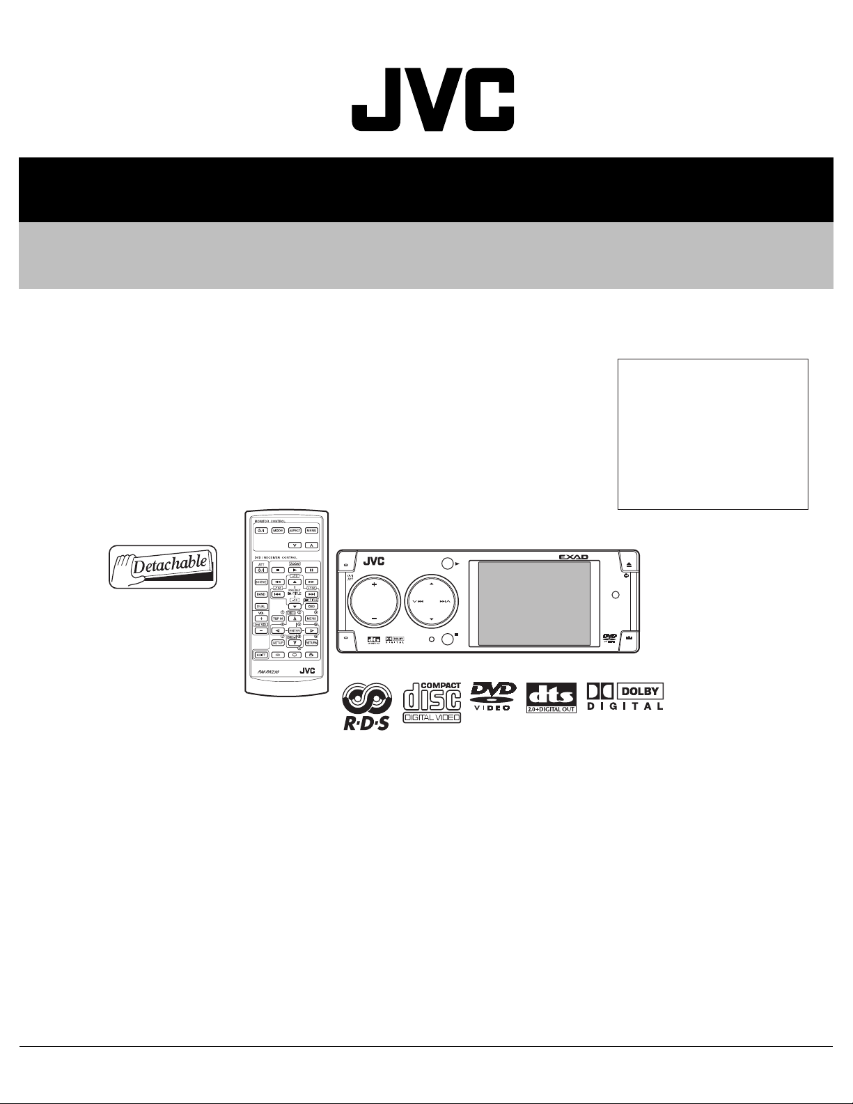
SERVICE MANUAL
DVD/CD RECEIVER
MA16520055
KD-AVX1
Area suffix
J ------------- Northern America
E ------------- Southern Europe
A ------------------------ Australia
UT ------------------------- Taiwan
UN --------------------- Indonesia
U -------------------- Other Areas
KD-AVX1
OK
DISP
SOURCE
MENU
D
T/P
Lead free solder used in the board (material : Sn-Ag-Cu, melting point : 219 Centigrade)
BACK
BAND
TABLE OF CONTENTS
1 PRECAUTIONS . . . . . . . . . . . . . . . . . . . . . . . . . . . . . . . . . . . . . . . . . . . . . . . . . . . . . . . . . . . . . . . . . . . . . . . 1-5
2 SPECIFIC SERVICE INSTRUCTIONS . . . . . . . . . . . . . . . . . . . . . . . . . . . . . . . . . . . . . . . . . . . . . . . . . . . . . . 1-8
3 DISASSEMBLY . . . . . . . . . . . . . . . . . . . . . . . . . . . . . . . . . . . . . . . . . . . . . . . . . . . . . . . . . . . . . . . . . . . . . . . 1-9
4 ADJUSTMENT . . . . . . . . . . . . . . . . . . . . . . . . . . . . . . . . . . . . . . . . . . . . . . . . . . . . . . . . . . . . . . . . . . . . . . . 1-26
5 TROUBLESHOOTING . . . . . . . . . . . . . . . . . . . . . . . . . . . . . . . . . . . . . . . . . . . . . . . . . . . . . . . . . . . . . . . . . 1-38
COPYRIGHT © 2005 Victor Company of Japan, Limited
No.MA165
2005/5
Page 2
SPECIFICATION
for NORTHERN AMERICA version
AUDIO AMPLIFIER SECTION
Power Output 20 W RMS
Signal to Noise Ratio 80 dBA (reference: 1 W into 4
Load Impedance 4
Equalizer Control Range Frequencies 60 Hz, 150 Hz, 400 Hz, 1 kHz, 2.5 kHz, 6.3 kHz, 15 kHz
Level ±10 dB
Line-In Level/Impedance 1.5 V/20 k
Line-Out Level/Impedance 5.0 V/20 k
Output Impedance 1 k
Subwoofer-Out Level/Impedance 2.0 V/20 kΩ load (full scale)
Color System NTSC
Video Input (composite) 1 Vp-p/75
Video Output (composite) 1 Vp-p/75 Ω
Other Terminals 2nd AUDIO OUT, DIGITAL OUT (optical), CD changer, Steering wheel re-
TUNER SECTION
Frequency Range FM 87.5 MHz to 107.9 MHz (with channel interval set to 200 kHz)
AM 530 kHz to 1 710 kHz (with channel interval set to 10 kHz)
FM Tuner Usable Sensitivity 11.3 dBf (1.0
50 dB Quieting Sensitivity 16.3 dBf (1.8
Alternate Channel Selectivity (400 kHz) 65 dB
Frequency Response 40 Hz to 15 000 Hz
Stereo Separation 35 dB
Capture Ratio 1.5 dB
AM Tuner Sensitivity 20
Selectivity 35 dB
DVD/CD PLAYER SECTION
Signal Detection System Non-contact optical pickup (semiconductor laser)
Number of Channels 2 channels (stereo)
Frequency Response DVD fs=48 kHz 16 Hz to 22 000 Hz
DVD fs=96 kHz 16 Hz to 44 000 Hz
VCD, CD, MP3, WMA 16 Hz to 20 000 Hz
Dynamic Range 93 dB
Signal-to-Noise Ratio 95 dB
Wow and Flutter Less than measurable limit
MP3 Max. Bit Rate 320 kbps
WMA (Windows Media Audio) Max. Bit Rate 192 kbps
MONITOR SECTION
Screen 3-inch liquid crystal panel
Number of Pixels 123 200 pixels
Drive Method TFT (Thin Film Transistor) active matrix format
Color system NTSC
Power Requirement Operating Voltage DC 14.4 V (11 V to 16 V allowance)
Grounding System Negative ground
Allowable Operating Temperature 0
Dimensions (W
Mass (approx.) 2.0 kg (4.5 lbs) (excluding accessories)
× H × D) Installation Size (approx.) 182 mm × 52 mm × 160 mm (7-3/16" × 2-1/16" × 6-5/16")
Panel Size (approx.) 188 mm
Ω (4 Ω to 8 Ω allowance)
Ω
mote input (OE REMOTE)
87.5 MHz to 108.0 MHz (with channel interval set to 50 kHz)
531 kHz to 1 602 kHz (with channel interval set to 9 kHz)
µV
GENERAL
° C to +40° C (32° F to 104° F)
× 4 Channels at 4 Ω and [< or =] 1% THD+N
Ω)
Ω load
Ω load (full scale)
Ω
µV/75 Ω)
µV/75 Ω)
× 58 mm × 18 mm (7-7/16" × 2-5/16" × 3/4")
1-2 (No.MA165)
Page 3
for EUROPE version
AUDIO AMPLIFIER SECTION
Maximum Power Output Front 50 W per channel
Rear 50 W per channel
Continuous Power Output (RMS) Front 20 W per channel into 4
harmonic distortion.
Rear 20 W per channel into 4
harmonic distortion.
Load Impedance 4
Equalizer Control Range Frequencies 60 Hz, 150 Hz, 400 Hz, 1 kHz, 2.5 kHz, 6.3 kHz, 15 kHz
Level ±10 dB
Signal-to-Noise Ratio 70 dB
Line-In Level/Impedance 1.5 V/20 k
Line-Out Level/Impedance 5.0 V/20 k
Output Impedance 1 k
Subwoofer-Out Level/Impedance 2.0 V/20 kΩ load (full scale)
Color System PAL
Video Input (composite) 1 Vp-p/75
Video Output (composite) 1 Vp-p/75 Ω
Other Terminals 2nd AUDIO OUT, DIGITAL OUT (optical), CD changer, Steering wheel re-
TUNER SECTION
Frequency Range FM 87.5 MHz to 108.0 MHz
AM (MW) 522 kHz to 1 620 kHz
FM Tuner Usable Sensitivity 11.3 dBf (1.0
50 dB Quieting Sensitivity 16.3 dBf (1.8
Alternate Channel Selectivity (400 kHz) 65 dB
Frequency Response 40 Hz to 15 000 Hz
Stereo Separation 35 dB
Capture Ratio 1.5 dB
MW Tuner Sensitivity 20
Selectivity 35 dB
LW Tuner Sensitivity 50
DVD/CD PLAYER SECTION
Signal Detection System Non-contact optical pickup (semiconductor laser)
Number of Channels 2 channels (stereo)
Frequency Response DVD fs=48 kHz 16 Hz to 22 000 Hz
DVD fs=96 kHz 16 Hz to 44 000 Hz
VCD, CD 16 Hz to 20 000 Hz
Dynamic Range 93 dB
Signal-to-Noise Ratio 95 dB
Wow and Flutter Less than measurable limit
MP3 Max. Bit Rate 320 kbps
WMA (Windows Media Audio) Max. Bit Rate 192 kbps
MONITOR SECTION
Screen 3-inch liquid crystal panel
Number of Pixels 123 200 pixels
Drive Method TFT (Thin Film Transistor) active matrix format
Color System PAL
GENERAL
Power Requirement Operating Voltage DC 14.4 V (11 V to 16 V allowance)
Grounding System Negative ground
Allowable Operating Temperature 0
Dimensions (W
Mass (approx.) 2.0 kg (excluding accessories)
× H × D) Installation Size (approx.) 182 mm × 52 mm × 160 mm
Panel Size (approx.) 188 mm
Ω (4 Ω to 8 Ω allowance)
Ω load
Ω load (full scale)
Ω
Ω
mote input (OE REMOTE)
(LW) 144 kHz to 279 kHz
µV/75 Ω)
µV/75 Ω)
µV
µV
°C to +40°C
× 58 mm × 18 mm
Ω, 40 Hz to 20 000 Hz at no more than 0.8% total
Ω, 40 Hz to 20 000 Hz at no more than 0.8% total
(No.MA165)1-3
Page 4
for ASIA & AUSTRALIA version
AUDIO AMPLIFIER SECTION
Maximum Power Output Front 50 W per channel
Rear 50 W per channel
Continuous Power Output (RMS) Front 20 W per channel into 4
harmonic distortion.
Rear 20 W per channel into 4
harmonic distortion.
Load Impedance 4
Equalizer Control Range Frequencies 60 Hz, 150 Hz, 400 Hz, 1 kHz, 2.5 kHz, 6.3 kHz, 15 kHz
Level ±10 dB
Signal-to-Noise Ratio 70 dB
Line-In Level/Impedance 1.5 V/20 k
Line-Out Level/Impedance 5.0 V/20 k
Output Impedance 1 k
Subwoofer-Out Level/Impedance 2.0 V/20 kΩ load (full scale)
Color System NTSC/PAL
Video Input (composite) 1 Vp-p/75
Video Output (composite) 1 Vp-p/75 Ω
Other Terminals 2nd AUDIO OUT, DIGITAL OUT (optical), CD changer
TUNER SECTION
Frequency Range FM 87.5 MHz to 108.0 MHz
AM 531 kHz to 1 602 kHz
FM Tuner Usable Sensitivity 11.3 dBf (1.0
50 dB Quieting Sensitivity 16.3 dBf (1.8
Alternate Channel Selectivity (400 kHz) 65 dB
Frequency Response 40 Hz to 15 000 Hz
Stereo Separation 35 dB
Capture Ratio 1.5 dB
AM Tuner Sensitivity 20
Selectivity 35 dB
DVD/CD PLAYER SECTION
Signal Detection System Non-contact optical pickup (semiconductor laser)
Number of Channels 2 channels (stereo)
Frequency Response DVD fs=48 kHz 16 Hz to 22 000 Hz
DVD fs=96 kHz 16 Hz to 44 000 Hz
VCD, CD 16 Hz to 20 000 Hz
Dynamic Range 93 dB
Signal-to-Noise Ratio 95 dB
Wow and Flutter Less than measurable limit
MP3 Max. Bit Rate: 320 kbps
WMA (Windows Media Audio) Max. Bit Rate 192 kbps
MONITOR SECTION
Screen 3-inch liquid crystal panel
Number of Pixels 123 200 pixels
Drive Method TFT (Thin Film Transistor) active matrix format
Color system NTSC/PAL
GENERAL
Power Requirement Operating Voltage DC 14.4 V (11 V to 16 V allowance)
Grounding System Negative ground
Allowable Operating Temperature 0
Dimensions (W
Mass (approx.) 2.0 kg (excluding accessories)
× H × D) Installation Size (approx.) 182 mm × 52 mm × 160 mm
Panel Size (approx.) 188 mm
Ω (4 Ω to 8 Ω allowance)
Ω load
Ω load (full scale)
Ω
Ω
µV/75 Ω)
µV/75 Ω)
µV
°C to +40°C
× 58 mm × 18 mm
Ω, 40 Hz to 20 000 Hz at no more than 0.8% total
Ω, 40 Hz to 20 000 Hz at no more than 0.8% total
Design and specifications are subject to change without notice.
1-4 (No.MA165)
Page 5
1.1 Safety Precautions
SECTION 1
PRECAUTIONS
!
!
Burrs formed during molding may be left over on some parts of the chassis. Therefore,
pay attention to such burrs in the case of preforming repair of this system.
Please use enough caution not to see the beam directly or touch it in case of an
adjustment or operation check.
(No.MA165)1-5
Page 6
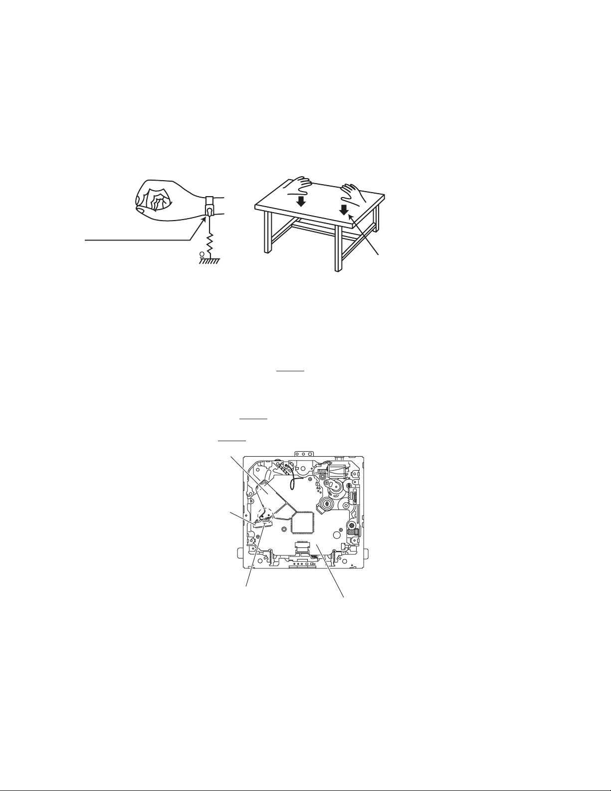
1.2 Preventing static electricity
Electrostatic discharge (ESD), which occurs when static electricity stored in the body, fabric, etc. is discharged, can destroy the laser
diode in the traverse unit (optical pickup). Take care to prevent this when performing repairs.
1.2.1 Grounding to prevent damage by static electricity
Static electricity in the work area can destroy the optical pickup (laser diode) in devices such as CD players.
Be careful to use proper grounding in the area where repairs are being performed.
(1) Ground the workbench
Ground the workbench by laying conductive material (such as a conductive sheet) or an iron plate over it before placing the
traverse unit (optical pickup) on it.
(2) Ground yourself
Use an anti-static wrist strap to release any static electricity built up in your body.
(caption)
Anti-static wrist strap
1M
Conductive material
(conductive sheet) or iron plate
(3) Handling the optical pickup
• In order to maintain quality during transport and before installation, both sides of the laser diode on the replacement optical
pickup are shorted. After replacement, return the shorted parts to their original condition.
(Refer to the text.)
• Do not use a tester to check the condition of the laser diode in the optical pickup. The tester's internal power source can easily
destroy the laser diode.
1.3 Handling the traverse unit (optical pickup)
(1) Before disconnecting the flexible wire from the connector CN101
on the flexible wire.
Caution:
If you do not follow this instruction, the DVD pickup may be damaged.
(2) Disconnect the flexible wire from the connector CN101
(3) Remove the solders from the short-circuit points on the flexible wire after replacing the DVD pickup.
(4) Connect the flexible wire to the connector CN101
Flexible wire
CN101
on the mechanism control board.
on the mechanism control board.
on the mechanism control board, solder the short-circuit points
1-6 (No.MA165)
Short-circuit points
Mechanism control board
Page 7
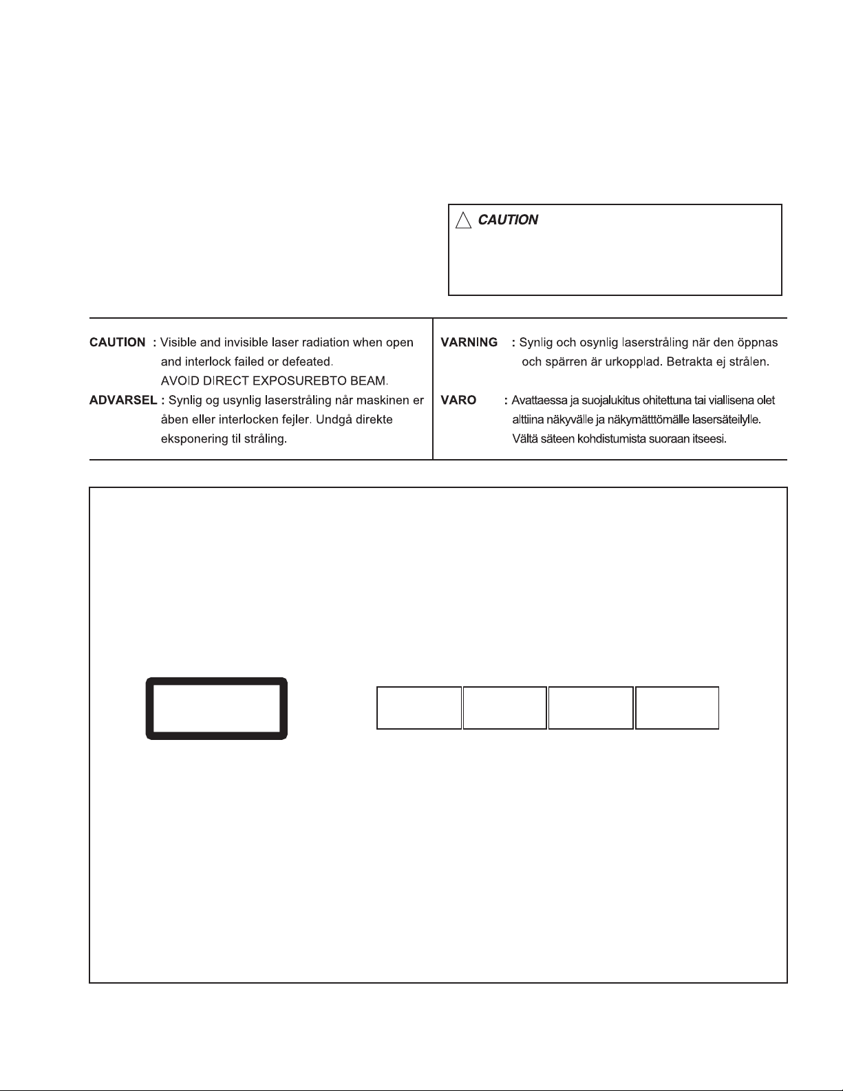
1.4 Important for laser products
!
1.CLASS 1 LASER PRODUCT
2.DANGER : Invisible laser radiation when open and inter
lock failed or defeated. Avoid direct exposure to beam.
3.CAUTION : There are no serviceable parts inside the
Laser Unit. Do not disassemble the Laser Unit. Replace
the complete Laser Unit if it malfunctions.
4.CAUTION : The CD,MD and DVD player uses invisible
laser radiation and is equipped with safety switches which
prevent emission of radiation when the drawer is open and
the safety interlocks have failed or are defeated. It is
dangerous to defeat the safety switches.
5.CAUTION : If safety switches malfunction, the laser is able
to function.
6.CAUTION : Use of controls, adjustments or performance of
procedures other than those specified here in may result in
hazardous radiation exposure.
Please use enough caution not to
see the beam directly or touch it
in case of an adjustment or operation
check.
REPRODUCTION AND POSITION OF LABELS
WARNING LABEL
CAUTION : Visible and Invisible
CLASS 1
LASER PRODUCT
laser radiation when open and
interlock failed or defeated.
AVOID DIRECT EXPOSURE TO
BEAM. (e)
ADVARSEL : Synlig og usynlig
laserstråling når maskinen er
åben eller interlocken fejeler.
Undgå direkte eksponering til
stråling. (d)
VARNING : Synlig och
osynling laserstrålning när
den öppnas och spärren är
urkopplad. Betrakta ej
strålen. (s)
VARO : Avattaessa ja suojalukitus
ohitettuna tai viallisena olet alttiina
näkyvälle ja näkymättömälle
lasersäteilylle. Vältä säteen
kohdistumista suoraan itseesi. (f)
(No.MA165)1-7
Page 8

SECTION 2
SPECIFIC SERVICE INSTRUCTIONS
This service manual does not describe SPECIFIC SERVICE INSTRUCTIONS.
1-8 (No.MA165)
Page 9
SECTION 3
DISASSEMBLY
3.1 Main body section
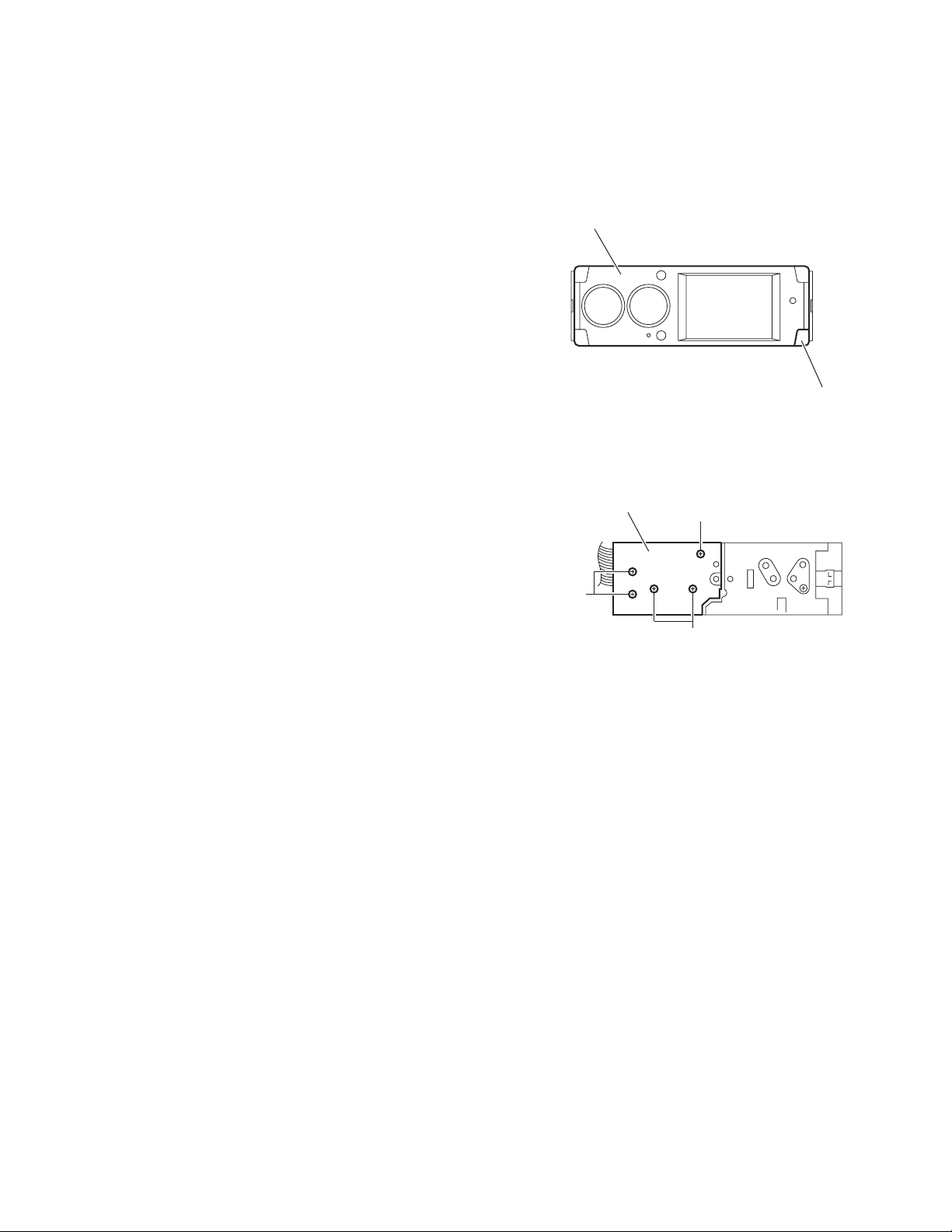
3.1.1 Removing the panel assembly
(See Fig.1)
(1) Push the button(detach) in the lower right part of the panel
assembly.
(2) Remove the panel assembly.
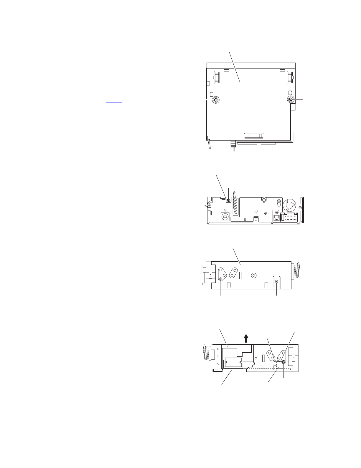
3.1.2 Removing the side heat sink
(See Fig.2)
Reference:
Remove the panel assembly as required.
(1) From the left side of the main body, remove the two screws
A and three screws B attaching the side heat sink.
(2) Remove the side heat sink from the main body.
Panel assembly
Side heat sink
Button(detach)
Fig.1
B
B
A
Fig.2
(No.MA165)1-9
Page 10
3.1.3 Removing the top chassis assembly
(See Figs.3 to 6)
• Remove the panel assembly and side heat sink.
(1) From the top side of the main body, remove the two screws
C attaching the top chassis assembly. (See Fig.3.)
(2) From the back side of the main body, remove the two
screws C attaching the top chassis assembly. (See Fig.4.)
(3) From the both sides of the main body, remove the two
screws C and screw D attaching the top chassis assembly.
(See Figs.5 and 6.)
(4) Lift the top chassis assembly in the direction of the arrow
and disconnect the connector CN966
board from the connector CN961
Fig.6.)
(5) Take out the top chassis assembly from the main body.
on the main sub
on the main board. (See
Top chassis assembly
C
Top chassis assembly
C
Fig.3
C
Fig.4
Top chassis assembly
C D
Fig.5
Top chassis assembly
Main board
Fig.6
Main sub board
CN961
C
CN966
1-10 (No.MA165)
Page 11
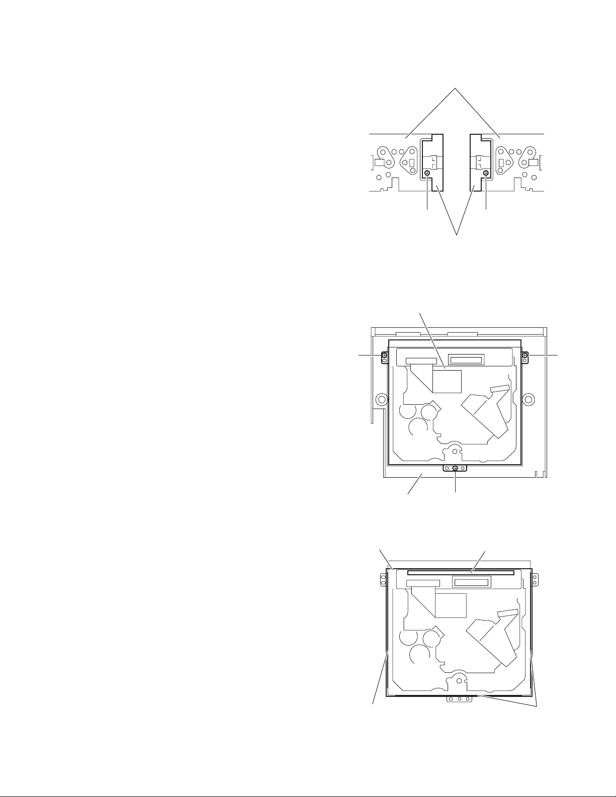
3.1.4 Removing the front chassis assembly
(See Fig.7)
• Remove the panel assembly, side heat sink and top chassis
assembly.
(1) From the both sides of the top chassis assembly, remove
the two screws E attaching the front chassis assembly.
(2) Remove the front chassis assembly from the top chassis
assembly.
3.1.5 Removing the DVD mechanism assembly
(See Figs.8 and 9)
• Remove the panel assembly, side heat sink and top chassis
assembly.
Reference:
Remove the front chassis assembly as required.
(1) From the inside of the top chassis assembly, remove the
three screws F attaching the DVD mechanism assembly
and take out the DVD mechanism assembly. (See Fig.8.)
(2) From the side of the DVD mechanism assembly, remove
the double-stick tape fixing the insulator. (See Fig.9.)
(3) From the top side of the DVD mechanism assembly, re-
move the spacer attaching the insulator. (See Fig.9.)
(4) Remove the insulator from the top chassis assembly.
Reference:
When the resolution of DVD mechanism assembly is done sequentially, remove the main sub board. (See next Fig.10.)
Top chassis assembly
E E
Front chassis assembly
DVD mechanism assembly
F
Fig.7
F
Top chassis assembly
Insulator
Double-stick tape
F
Fig.8
Spacer
Double-stick tape
Fig.9
(No.MA165)1-11
Page 12
3.1.6 Removing the main sub board
(See Fig.10)
• Remove the panel assembly, side heat sink, top chassis as-
sembly and DVD mechanism assembly.
(1) From the top side of the DVD mechanism assembly, re-
lease the lock of the connector CN965
board and disconnect the card wire.
(2) Remove the two screws G attaching the main sub board on
the DVD mechanism assembly and remove the main sub
board.
Reference:
When attaching the main sub board, align the projections a in
the holes of the main sub board before attaching the screws G.
3.1.7 Removing the loading unit assembly
(See Fig.11)
• Remove the panel assembly, side heat sink and top chassis
assembly.
(1) From the inside of the main body, disconnect the wire from
the connector CN881
(2) Remove the two screws H attaching the loading unit as-
sembly.
(3) Remove the tension spring and take out the loading unit
assembly.
Note:
When disassembling, do not lose the tension spring.
on the main board.
on the main sub
a
G
Lock
Main board
Main sub board
CN965
DVD mechanism assembly
Fig.10
Motor bracket assembly
CN881
a
G
H
3.1.8 Removing the arm bracket assemblies (L)/(R)
(See Fig.12)
• Remove the panel assembly, side heat sink, top chassis as-
sembly and loading unit assembly.
(1) Remove the two screws J and screw K attaching the arm
bracket assembly (L).
(2) Take out the arm bracket assembly (L).
(3) Remove the two screws J and screw K attaching the arm
bracket assembly (R).
(4) Take out the arm bracket assembly (R).
3.1.9 Removing the front bracket assembly
(See Fig.12.)
• Remove the panel assembly, side heat sink and top chassis
assembly.
(1) Release the lock of the connector CN962
board in an upward direction and disconnect the flexible
wire.
(2) Remove the four screws K attaching the front bracket as-
sembly and take out the front bracket assembly.
on the main
Fig.11
Arm bracket assembly (L)
Main board
J
CN962
Tension spring
H
Arm bracket assembly (R)
J
Lock
1-12 (No.MA165)
Front bracket assembly
K
K
Fig.12
Page 13

3.1.10 Removing the connector board
(See Figs.13 to 15)
• Remove the panel assembly, side heat sink, top chassis as-
sembly and front bracket assembly.
(1) From the front side of the front bracket assembly, remove
the two screws M. (See Fig.13.)
(2) Remove the joints b and remove the detach lever from the
front bracket assembly. (See Fig.13.)
Reference:
When attaching the detach lever, insert the end of the
torsion spring in the hole c of the front bracket assembly.
(See Fig.13.)
(3) From the back side of the front bracket assembly, remove
the screw N attaching the connector cover. (See Fig.14.)
(4) Remove the connector cover in the direction of the arrow
while releasing the tabs d in an upward direction. (See
Fig.14.)
(5) Remove the reinforce plate and take out the connector
board from the front bracket assembly. (See Fig.15.)
Front bracket assembly
Fig.13
Connector cover
d
N
Fig.14
Connector board
M
Detach lever
Torsion spring
b
c
b
d
Reinforce plate
Front bracket assembly
Fig.15
(No.MA165)1-13
Page 14

3.1.11 Removing the main board
(See Figs.16 and 17)
• Remove the panel assembly, side heat sink, top chassis as-
sembly, loading unit assembly and arm bracket assemblies
(L)/(R).
(1) From the back side of the main body, remove the screw P
attaching the rear bracket. (See Fig.16.)
(2) From the top side of the main body, take out the rod gear.
(See Fig.17.)
Reference:
When attaching the rod gear, attach the washers with it
as before. (See Fig.17.)
(3) Release the lock of the connector CN962
board in an upward direction and disconnect the flexible
wire. (See Fig.17.)
(4) Release the lock of the connector CN891
the card wire. (See Fig.17.)
(5) Remove the three screws P attaching the main board to the
bottom chassis assembly. (See Fig.17.)
(6) Take out the main board from the bottom chassis assem-
bly.
Reference:
When attaching the main board, attach the main board under
the sections e of the bottom chassis assembly as before. (See
Fig.17.)
on the main
and disconnect
Rear bracket
Bottom chassis assembly
Rod gear
Washer
P
P
Fig.16
e
CN962
Lock
e
Washer
Lock
P
Main board
CN891
Fig.17
1-14 (No.MA165)
Page 15

3.1.12 Removing the rear bracket
(See Fig.18)
• Remove the panel assembly, side heat sink, top chassis as-
sembly, loading unit assembly, arm bracket assemblies (L)/(R)
and main board.
(1) From the back side of the main board, remove the two
screws Q attaching the rear heat sink.
(2) Remove the three screws R, screw R' and screw S attach-
ing the rear bracket.
Reference:
When attaching the screw R', attach the wire holder with
it as before.
(3) Remove the joints f of the rear bracket in the direction of
the arrow.
(4) Remove the car cable in the direction of the arrow from the
rear bracket.
3.1.13 Removing the panel switch board
(See Fig.19)
• Remove the panel assembly, side heat sink, top chassis as-
sembly, loading unit assembly, arm bracket assemblies (L)/(R)
and main board.
(1) From the inside of the bottom chassis assembly, take out
the insulator.
(2) Remove the two screws T attaching the panel switch
board.
(3) Take out the panel switch board from the bottom chassis
assembly.
Wire holder
R'
Rear bracket
Insulator
Car cable
R
Rear heat sink
Q
Fig.18
Panel switch board
R
f
S
Bottom chassis assembly
Fig.19
T
(No.MA165)1-15
Page 16

3.1.14 Removing the panel board
(See Figs.20 and 21)
• Remove the panel assembly.
(1) From the back side of the panel assembly, remove the sev-
en screws U attaching the rear cover to the panel assembly. (See Fig.20.)
(2) From the inside of the rear cover, release the lock of the
connector CN582
card wire. (See Fig.21.)
(3) Remove the five screws V attaching the panel board and
take out the panel board from the rear cover. (See Fig.21.)
3.1.15 Removing the switch board
(See Figs.20 and 22)
• Remove the panel assembly.
(1) From the back side of the panel assembly, remove the sev-
en screws U attaching the rear cover to the panel assembly. (See Fig.20.)
(2) From the inside of the panel assembly, release the lock of
the connector CN583
the card wire. (See Fig.22.)
(3) Take out the switch board from the panel assembly.Take
out the switch board from the panel assembly.
Note:
Do not lose the compression spring when taking out the switch
board. (See Fig.22.)
on the panel board and disconnect the
on the switch board and disconnect
U
U
Panel board
V
Rear cover
Fig.20
Rear cover
CN582
U
Front panel assembly
Lock
V
V
Fig.21
Lock
Compression spring
CN583
Fig.22
Panel assembly
Switch board
1-16 (No.MA165)
Page 17

3.2 DVD mechanism assembly
3.2.1 Removing the mechanism control board
(See Fig.1)
Caution:
Before disconnecting the flexible wire extending from the DVD
pickup, solder the short-circuit point on the flexible wire using
a grounding soldering iron. If you do not follow this instruction,
the DVD pickup may be damaged.
(1) Turn over the body, and solder the short-circuit points on
the flexible wire extending from the DVD pickup.
(2) Disconnect the flexible wire from connector CN101
mechanism control board.
(3) Disconnect the card wire from connector CN201
mechanism control board.
(4) Disconnect the flexible wire from connector CN202
mechanism control board.
(5) Unsolder two soldered points a on the mechanism control
board and remove the wire extending from the feed motor.
(6) Remove the screw A attaching the lug wire.
(7) Remove the two screws B and screw C attaching the
mechanism control board.
Caution:
• As the flexible wire to be connected to CN101
attach it to the mechanism control board using a double
tape.
• After reassembling, unsolder the short-circuit points.
on the
on the
on the
, make sure to
Flexible wire
Double tape
CN101
B
Short-circuit points
A
Lug wire
B
CN201
Feed motor
a
C
CN202
Mechanism control board
Fig.1
(No.MA165)1-17
Page 18

3.2.2 Removing the top cover
(See Fig.2)
(1) Remove the two screws D attaching the top cover on the
back of the body.
(2) Remove the top cover upward.
Reference:
When reassembling, set part b of the top cover under the
bending part c of the chassis frame.
3.2.3 Removing the mechanism section
(See Fig.2 to 4)
• Remove the top cover.
(1) From the bottom of the body, remove the screw E attaching
the lug wire. (See Fig.2.)
(2) Remove the two screws F attaching the right and left stop-
pers on the front side. (See Fig.2.)
(3) Remove the two floating springs on the bottom of the body.
(See Fig.3.)
(4) Move the mechanism section upward and remove from the
chassis frame.
The three damper springs come off from the dampers.
(See Fig.4.)
Caution:
• When reassembling, reattach the damper spring to the
damper respectively and insert the three shafts on the bottom of the mechanism to the dampers.
• Before inserting the shaft to the dampers, apply IPA to the
hole of damper.
Floating spring
Fig.3
Mechanism section
Stopper
F
Top cover
Stopper
F
D
D
b
c
E
Lug wire
Damper SP.(F)
(Silver)
Damper (F)
(Black)
Damper SP.(F)
(Silver)
Damper (F)
(Black)
Fig.4
Damper SP.(R)
(Red)
Damper (R)
(Purple)
Chassis frame
1-18 (No.MA165)
Fig.2
Page 19

3.2.4 Removing the clamper unit
(See Fig.5 to 7)
• Remove the top cover and the mechanism section.
(1) Remove the clamper2 spring on the bottom of the mecha-
nism section. (See Figs.5.and 6.)
(2) Release the part d of the clamper spring from the bending
part of the chassis base assembly. (See Fig.7.)
(3) Move the clamper unit in the direction of the arrow and turn.
Release the two joints e and f, then remove the clamper
unit upward. (See Fig.6.)
3.2.5 Reattaching the clamper unit
(See Fig.5 to 9)
(1) Attach the clamper spring to the clamper unit. (See Fig.8.)
(2) Move the clamper unit to set the side joints e and f to each
boss of the chassis base assembly. Make sure that part g
is inserted to the notch of the chassis base assembly. (See
Figs.5 and 9.)
(3) Move the part d of the clamper spring to the outside of the
bending part of the chassis base assembly. (See Fig.7.)
(4) Attach the clamper2 spring to the chassis base assembly.
(See Figs.5 and 6.)
Caution:
When reattaching, temporarily hook the end of the clamper
spring as shown in the figure to make the work easy. (See
Fig.8.)
Clamper unit
Clamper2 spring
Chassis base assembly
Fig.6
Clamper spring
Clamper spring
f
Clamper2 spring
Chassis base assembly
g
d
Chassis base assembly
Fig.7
e
Fig.5
(No.MA165)1-19
Page 20

Clamper unit
Clamper unit
Clamper spring
Fig.8
1-20 (No.MA165)
Fig.9
g
Notch
Page 21

3.2.6 Removing the front unit
(See Fig.10 to 12)
• Remove the top cover and the mechanism section.
(1) Disconnect the flexible wire from connector CN202
mechanism control board at the bottom of the body. (See
Fig.10.)
(2) Remove the screw G attaching the front unit on the top of
the body. (See Fig.11.)
(3) Move the front unit toward the front to release joint h, and
release two joints i and j on the right side of the chassis
base assembly. Then remove the front unit upward. (See
Figs.11 and 12.)
(4) Remove the two screws H attaching the switch board. (See
Fig.12.)
Reference:
You can remove the switch board only without removing the
front unit.
Caution:
When reassembling, attach the flexible wire extending from
the switch board using the double tape. (See Figs.10 and 12.)
Mechanism control board
on the
G
Front unit
h
Fig.11
CN202
Double tape
Fig.10
Flexible wire
Double tape
j
i
H
Switch board
Front unit
G
Fig.12
h
(No.MA165)1-21
Page 22

3.2.7 Removing the loading arm assembly
(See Fig.13 , 14)
• Remove the top cover, the mechanism section and the front
unit.
(1) From the top of the body, move the loading arm assembly
from the front side upward, and release the bosses from
the right and left joints k and m of the chassis base assembly.
(2) Release the boss from notch n of the connect arm on the
right side of the body, and release the boss from notch p of
the slide cam assembly on the left side.
m
Loading arm assembly
Side cam
assembly
p
m
k
Fig.13
Loading arm assembly
k
n
n
Connect arm
1-22 (No.MA165)
Fig.14
Page 23

3.2.8 Removing the rod (L)(R)/roller assembly
(See Fig.15 and 16)
• Remove the top cover, the mechanism section, the front unit
and the loading arm assembly.
(1) Release the rod (L) and (R) from the joints q at the bottom
of the loading arm assembly (See Fig.15.)
(2) Remove the roller assembly from the loading arm assem-
bly. (See Fig.16.)
(3) Remove the two collars and washer from the roller assem-
bly. (See Fig.16.)
Caution:
After attaching the loading arm assembly to the roller assembly, attach the rod (L) and (R). Attach the rods to the right and
left collars of the roller. (See Fig.15.)
When reattaching the rod (L) and (R) to the loading arm assembly, engage each joint as shown in Fig.15. As joints q of
the rod (L), let the rod through q before reattaching it.
Collar
Collar
Rod(R) Rod(L)
q
q
q
Collar
Rod(L)
Rod(R)
q
Loading arm assembly
Fig.15
Roller assembly
Loading arm assembly
q
Rod(L)
q
Collar
Washer
Rod(R)
Fig.16
(No.MA165)1-23
Page 24

3.2.9 Removing the DVD pickup assembly
(See Fig.17 to 19)
• Remove the mechanism control board.
(1) From the bottom of the body, turn the feed gear in the di-
rection of the arrow to move the DVD pickup outwards.
(See Fig.17.)
(2) Remove the screw J attaching the thrust spring. (See
Fig.17.)
(3) Remove the DVD pickup assembly upward on the L.S.gear
side and release from sub shaft at joint r. Move the lead
screw of the DVD pickup assembly in the direction of the
arrow to release from joint s. (See Fig.18.)
Caution:
• When releasing the lead screw at joint s, the L.S.collar
comes off at the end of the lead screw. When reassembling, reattach the L.S.collar to the lead screw and
engage joint s. (See Fig.18.)
• When reattaching the L.S.collar, reattach it to the point
s of the lead screw, and to the rod (M). Make sure that
the L.S.collar is set on the rod (M) spring. (See Fig.18.)
(4) Remove the screw K attaching the rack spring/ rack plate
on the DVD pickup. (See Fig.19.)
(5) Pull out the lead screw. (See Fig.19.)
Caution:
Perform adjustment after replacing the pickup.
DVD Pickup assembly
DVD Pickup assembly
Feed gear
J
Thrust spring
Fig.17
s
L.S.collar
Rod(M)
Lead screw
Sub shaft
L.S.collar
r
L.S.gear
Fig.18
K
Rack spring
Lead screw
Rack plate
DVD Pickup
Fig.19
1-24 (No.MA165)
Page 25

3.2.10 Removing the spindle motor
r
(See Fig.20)
• Remove the mechanism control board.
Remove the two screws L attaching the spindle motor on the
bottom of the body.
Caution:
Perform adjustment when reattaching the spindle motor.
3.2.11 Removing the feed motor assembly
(See Fig.21 and 22)
• Remove the mechanism control board.
(1) Remove the feed TRI. spring on the bottom of the body.
(See Fig.21.)
(2) Remove the two screws M attaching the feed motor as-
sembly. (See Fig.21.)
(3) Remove the slit washer from the motor H. assembly and
pull out the worm wheel. (See Fig.22.)
Remove the two screws N attaching the feed motor. (See
Fig.22.)
Spindle motor
Feed TRI. spring
L
Fig.20
M
Feed motor assembly
Fig.21
Slit washer
Worm wheel
Feed moto
N
Motor H. assembly
Fig.22
(No.MA165)1-25
Page 26

SECTION 4
ADJUSTMENT
4.1 Test instruments required for adjustment
(1) Digital oscilloscope (100MHz)
(2) Jitter meter
(3) Digital tester
(4) Electric voltmeter
(5) Tracking offset meter
(6) Test Disc : VT501 or VT502
(7) Extension studs : STDV001-3P
(8) Extension cable : EXTDV002-30P
4.3 Connection method
Connection procedure
(1) Attach the front chassis assembly to the main board.
(2) Attach the heat sink and rear bracket to the main board.
(3) Attach the extension studs to the DVD mechanism assembly.
(4) Connect the DVD mechanism assembly and the main board with a extension cable.
4.2 Standard measuring conditions
Power supply voltage DC14.4V(11 to 16V)
Load impedance 4Ω(2 Speakers connection)
Line Output 20KΩ
Caution:
Be sure to attach the heat sink and rear bracket onto the power
amplifier IC and regulator IC respectively, before supply the
power. If voltage is applied without attaching these parts, the
power amplifier IC and regulator IC will be destroyed by heat.
Extension cable
EXTDV002-30P
Heat sink
Extension studs
STDV001-3P
Rear bracket
Extension stud
STDV001-3P
1-26 (No.MA165)
Page 27

4.4 Adjustment method for jitter
After replacing the pickup, set the unit in the service mode to display a jitter value on the LCD.
Confirm that the jitter value measured with a jitter meter is within 12% of the jitter value displayed on the LCD. If it is within 12%, then
adjustment is not necessary.
If the measured jitter value is outside the 12% tolerance range, perform the following adjustments.
4.4.1 Adjustment procedure
(1) Connect each unit shown in Fig.1.
(2) Set the unit to the service mode and display a jitter value (hex data) on the LCD.
(3) Turn each of the screws a, b and c, by a half-turn per step, in the direction that reduces the jitter value in order to minimize it .
(Do not turn a screw more than a half turn at a time, but adjust the screws in the cycle of a → b → c → a.)
(4) After completing the adjustment, secure the screws with screw lock paint.
c
b
a
Jitter value adjustment procedure (Pickup horizontal level adjustment relative to the DVD recording surface)
(For the adjustment tool use a 3 mm wrench and not a screwdriver, this procedure will make the adjustment easier.)
3 mm wrench
(No.MA165)1-27
Page 28

4.5 Jitter value conversion table
Load the test DVD and set the unit to the service mode. A jitter value converted to the hex value is displayed on the LCD. Refer to the
corresponding decimal notation value shown in the following Jitter Conversion Table.
The adjustment is OK if the jitter value measured with a jitter meter is within 12% of the jitter value displayed on the LCD.
If the measured jitter value is outside the 12% tolerance range, adjust it to minimize the difference between the measured value and
the displayed value.
Indicated
on the LCD
EF56
EF22
EEEE
EEBA
EE86
EE52
EE1E
EDEA
EDB6
ED82
ED4E
ED1A
ECE6
ECB2
EC7E
EC4A
EC16
EBE2
EBAE
EB7A
EB46
EB12
EADE
EAAA
EA76
EA42
EA0E
E9DA
E9A6
E972
E93E
E90A
E8D6
E8A2
E86E
E83A
E806
E7D2
Jitter value
(%)
4.7
4.8
4.9
5.0
5.1
5.2
5.3
5.4
5.5
5.6
5.7
5.8
5.9
6.0
6.1
6.2
6.3
6.4
6.5
6.6
6.7
6.8
6.9
7.0
7.1
7.2
7.3
7.4
7.5
7.6
7.7
7.8
7.9
8.0
8.1
8.2
8.3
8.4
Indicated
on the LCD
E79E
E76A
E736
E702
E6CE
E69A
E666
E632
E5FE
E5CA
E596
E562
E52E
E4FA
E4C6
E492
E45E
E42A
E3F6
E3C2
E38E
E35A
E326
E2F2
E2BE
E28A
E256
E222
E1EE
E1BA
E186
E152
E11E
E0EA
E0B6
E082
E04E
E01A
Jitter value
(%)
8.5
8.6
8.7
8.8
8.9
9.0
9.1
9.2
9.3
9.4
9.5
9.6
9.7
9.8
9.9
10.0
10.1
10.2
10.3
10.4
10.5
10.6
10.7
10.8
10.9
11.0
11.1
11.2
11.3
11.4
11.5
11.6
11.7
11.8
11.9
12.0
12.1
12.2
Indicated
on the LCD
DFE6
DFB2
DF7E
DF4A
DF16
DEE2
DEAE
DE7A
DE46
DE12
DDDE
DDAA
DD76
DD42
DD0E
DCDA
DCA6
DC72
DC3E
DC0A
DBD6
DBA2
DB6E
DB3A
DB06
DAD2
DA9E
DA6A
DA36
DA02
D9CE
D99A
D966
D932
D8FE
D8CA
D896
D862
Jitter value
(%)
12.3
12.4
12.5
12.6
12.7
12.8
12.9
13.0
13.1
13.2
13.3
13.4
13.5
13.6
13.7
13.8
13.9
14.0
14.1
14.2
14.3
14.4
14.5
14.6
14.7
14.8
14.9
15.0
15.1
15.2
15.3
15.4
15.5
15.6
15.7
15.8
15.9
16.0
Calculation
1-28 (No.MA165)
Indicated on the LCD Jitter (%)
E9A6 7.5
Page 29

4.6 Service mode
4.6.1 Standard input/output conditions
Power supply voltage DC14.4V(11 to 16V)
Load impedance 4Ω(2 Speakers connection)
Line Output 20KΩ
4.6.2 Service mode setting procedure
(The DVD does not need to be loaded before starting the following procedure.)
[STANDBY/ON ATTENUATOR] button
[MENU] button
[UP] button
[VOLUME+/VOLUME-] button
[OK] button
[EJECT] button
4.6.3 Operation procedures
1. Service mode 1 (Indication is displayed in SERVICE MODE.)
Keep this state more than 2 seconds
while continuing pressing the
[STANDBY/ON ATTENUATOR] button
and [EJECT] button sequentially.
Screen indication
SERVICE MODE
NO EJECT
EMERGENCY EJECT12
[BACK] button
[DOWN] button
Exchanging it operate a menu of a service mode with the [UP] button
and [DOWN] button. Operate choice of a menu with a [OK] button.
1 : When an [OK] button is pushed in NO EJECT indication, it is set
by an EJECT prohibition mode.
When an [OK] button is pushed in EJECT OK indication, it is set
by a normal mode.
2 : Forced EJECT movement
A screen becomes normal indication after an OK button was pushed.
[F.SKIP] button[B.SKIP] button
[DISPLAY] button
(No.MA165)1-29
Page 30

2. Service mode 2
Keep this state more than 2 seconds
while continuing pressing the
[DISP] button, [VOLUME-] button
and [EJECT] button sequentially.
Screen indication
SERVICE MODE2
INITIALIZE DVD
3. Service mode 3
Keep this state more than 2 seconds
while continuing pressing the
[DISP] button, [VOLUME+] button
and [EJECT] button sequentially.
SERVICE MODE 2
OK
Press the [OK] button.
Full initialization of EEPROM of a DVD unit
(It is included a permanent domain)
After clear completion, this indication is continued
till an effective key is input. (OK )
Screen indication
SERVICE MODE3
INITIALIZE ALL
INITIALIZE
SERVICE MODE
RUNNING MODE
Exchanging it operate a menu of a service mode with the [UP] button
and [DOWN] button. Operate choice of a menu with a [OK] button.
INITIALIZE ALL (Each EEPROM is initialized by a factory shipment state.)
Main micon EEPROM initialization (except a ROM correction domain)
Panel micon EEPROM initialization
(except factory adjustment data domain and ROM correction domain)
DVD unit EEPROM initialization (except a permanent domain)
After clear completion, a screen returns to normal indication after OK indication was
displayed for three seconds.
INITIALIZE (Initialization of a user area of each EEPROM)
Main micon EEPROM initialization (a user entry domain and picture adjustment data)
DVD unit EEPROM initialization (except a permanent domain)
After clear completion, a screen returns to service mode indication after OK indication
was displayed for three seconds.
1-30 (No.MA165)
A
Page 31

A
Screen indication
SERVICE MODE
VERSION
AREA/REGION
TEMPERATURE
MEMORY CHECK
DVD NTSC/PAL
DVD CHECK MODE
Exchanging it operate a menu
of a service mode with the [UP]
button and [DOWN] button.
Operate choice of a menu with
a [OK] button.
Return to previous menu with
a [BACK] button.
SERVICE MODE
ERROR READ
ERROR CLEAR
VERSION
MAIN
JD4
CH
PANEL
Micon version indication
Main micon version and ROM correction version
JD4 version
CH version
Panel micon version and ROM correction version
AREA/REGION
SYS-AREA
JD4-AREA
JD4-REGION
:
:
:
Area and region indication
Main micon area
JD4 area
JD4 region
TEMPERATURI Temperature data reading
Temparature data by the temperature sensor in the
main micon is read every 5 seconds and displayed
in hex numbers.
MEMORY CHECK
Memory residual quantity indication mode
Data residual quantity of a disc is displayed by LCD.
About the plaback control-related key ([FSKIP],
[BSKIP], [UP], [DOWN], [VOL]), only movement is
effective.
Indication does not change as memory residual
quantity indication.
About cancellation of this mode, press the
[STANDBY/ON ATTENUATOR] button.
DVD NTSC/PAL
NTSC
PAL
DVD picture change
JD4 output picture setting
(NTSC)
JD4 output picture setting
(PAL)
DVD CHECK MODE
See "DVD CHECK MODE" for details.
B
C
(No.MA165)1-31
Page 32

B
C
ERROR READ
DVD ERROR READ
CD ERROR READ
MECHA ERROR READ
DVD ERROR READ
E-1
:
E-2
:
E-3
:
E05
:
TOTAL
:
E04
E03
E02
E01
:
:
:
:
Reading of a DVD unit error history
Reading of a history of an error stored in
a DVD unit
Indication of latest three error codes and
first five error code
Indication of total error count
Error code
Detailed error code
CH ERROR READ
E-1
:
E-2
:
E-3
:
E05
:
TOTAL
:
E04
E03
E02
E01
:
:
:
:
ERROR CLEAR
DVD ERROR CLEAR
CD ERROR CLEAR
MECHA ERROR CLEAR
Reading of a CH changer error history
Reading of a history of an error stored in
a DVD unit
Indication of latest three error codes and
first five error code
Indication of total error count
Error code
Detailed error code
MECHA ERROR READ
E-1
:
E-2
:
E-3
:
E05
:
TOTAL
:
E04
E03
E02
E01
:
:
:
:
Reading of a door mechanism error history
Reading of a history of an error stored in
a DVD unit
Indication of latest three error codes and
first five error code
Indication of total error count
Error code
Detailed error code
Clear of each error history
A screen returns to following
indication after clear completion.
1-32 (No.MA165)
RUNNING MODE
See "Running mode" for details.
Page 33

4. Service mode 4
Keep this state more than 2 seconds
while continuing pressing the
[DISP] button, [BACK] button and
[EJECT] button sequentially.
Screen indication
SERVICE MODE4
RDS S MODE
MONITOR S MODE
Exchanging it operate a menu of a service mode with the [UP] button
and [DOWN] button. Operate choice of a menu with a [OK] button.
4.6.4 DVD check mode
DVD CHECK MODE
NORMAL PLAY
EF OUT-TRACKING OFF
EF IN-TRACKING OFF
CD-LASER ON
DVD-LASER ON
DVDx1 JITTER MODE
Exchanging it operate a menu of a service mode with the [UP] button
and [DOWN] button. Operate choice of a menu with a [OK] button.
NORMAL PLAY
EF OUT-TRACKING OFF
EF IN-TRACKING OFF
CD-LASER ON
DVD-LASER ON
DVDx1 JITTER MODE
EEPROM DATA DISP
EEPROM DATA CLEAR
TEMPERATURE
SEARCH & JITTER
MONITOR
PLAY
STOP
OPEN
CLOSE
Command
RDS S MODE
VER=V
SPI=
PI =
TP =
MS =
MONITOR S MODE
R/W CHROMA 1
R/W CHROMA 2
DATA CLEAR
PTY=
SM =
SQ =
TA =
PI =
RDS service mode
Only RDS model
See "Monitor adjustment" for details.
CHROMA DATA read/write of NTSC/PAL signal processing IC
CHROMA DATA read/write of TFT driver IC
Clear of CHROMA DATA of 1,2 (return to an initial value)
DVD CHECK MODE
EEPROM DATA DISP
EEPROM DATA CLEAR
TEMPERATURE
SEARCH & JITTER
MONITOR
PLAY
Mechanism unit operation Indication contents
Start at normal speed
(After start, jitter is measured by an inner position.)
Tracking off the outermost position of CD
Tracking off the innermost position of CD
CD_LD lights and laser current is displayed.
DVD_LD lights and laser current is displayed.
DVD x1 jitter measuring mode
(for use in mechanism adjustment)
Contents of EEPROM is displayed.
Contents of EEPROM is initialized.
Temperature indication
The search and jitter measurement to an appointed
position of DVD.
Monitor terminal setting
DVDx1 speed start
(After start, jitter is measured by an inner position.)
Disc stopped, LD-OFF
OPEN
CLOSE
DVD CHECK MODE
STOP
OPEN
CLOSE
Laser current value, jitter value
For EF phase error
For EF phase error
Laser current value, jitter value
Laser current value, jitter value
Laser current value, jitter value
EEPROM address
EEPROM contents
EEPROM address
EEPROM contents
Temperature is displayed in hex
numbers.
Position measured with VT-501
Jitter value
Not displayed.
Not displayed.
Not displayed.
Not displayed.
(No.MA165)1-33
Page 34

4.6.5 Error code tables
Mechanism error code
Error contents
Disc loading error
B1 time out
C1 time out
D1 time out
C2 time out
B2 time out
A2 time out
F1 time out
A0 (Switch state without existence)
G1 time out
Eject error
F2 time out
A1 time out
B1 time out
C1 time out
D1 time out
C2 time out
B2 time out
A0 (Switch state without existence)
G2 time out
Error in loading wait
Loading re-execution NG Eject
Eject re-execution NG Loading
Details Error code
Loading of a running mode
Disc was pulled out in a wait.
Running mode error
Running mode error
0x99
0x99
0x99
0x99
0x99
0x99
0x99
0x99
0x99
0x01
0x01
0x01
0x01
0x01
0x01
0x01
0x01
0x01
0x09
0x09
0x01
Detailed error code
0x0011
0x0012
0x0013
0x0014
0x0015
0x0016
0x0017
0x0018
0x0019
0x0021
0x0022
0x0023
0x0024
0x0025
0x0026
0x0027
0x0028
0x0029
0x0031
0x0032
0x0033
Disc error code
Error contents
TOC read error
First track access error
Last track access error
T1 access error
T12 access error
T24 access error
Read-in area read error
SDRAM read/write error
DVD L1 layer adjustment error
NODISC judgment
It is NODISC by start failure.
It is stopped by playback inability.
Details Error code
TOC lead movement of a CD is not completed.
Even if TOC reading passes after the end with
CD running mode for 30 seconds, the first track
access is not finished.
Even if first track passes after the end with
CD running mode for 30 seconds, the last track
access is not finished.
Even if T1 access passes in a DVD running
mode for 30 seconds, it is not finished.
Even if T12 access passes in a DVD running
mode for 30 seconds, it is not finished.
Even if T24 access passes in a DVD running
mode for 30 seconds, it is not finished.
Read-in area read operation of DVD is not
completed.
Read/write to SDRAM is not normal.
Adjustment of L1 layer of DVD is not finished
normally. (including focus jump failure)
Judgment without disc
Start is impossible.
Stop in running mode playback
0x84
0x80
0x80
0x80
0x80
0x80
0x84
0x80
0x80
0x80
0x80
0x80
Detailed error code
0x0059
0x0060
0x0061
0x0069
0x0070
0x0071
0x0072
0x0073
0x0074
0x0090
0x0091
0x0093
1-34 (No.MA165)
Page 35

4.6.6 Running mode
Indication
RUNNING1 MECHA
RUNNING2 MECHA
RUNNING3 DVD
RUNNING4 DVD
RUNNING5 DVD
RUNNING6 DVD
RUNNING7 DVD
RUNNING8 DVD
Explanation
Door mecha running1
Door mecha running1
DVD+Door mecha running1
DVD+Door mecha running2
DVD+Door mecha running3
DVD+Door mecha running4
DVD+Door mecha running5
DVD+Door mecha running6
Operation contents of 1 cycle
Panel close Panel open
Panel close Panel open Panel detach position
Panel angle 3 position Panel angle 1 position
Panel angle 2 position
Loading Eject Wait for 5 seconds+Door open/close
Loading Eject Wait for 5 seconds+Door open/close
Loading Playback Eject Wait for 5 seconds+Door open/close
Loading Playback Eject Wait for 5 seconds+Door open/close
Loading Playback Eject Wait for 5 seconds+Door open/close
Loading Playback Eject Wait for 5 seconds+Door open/close
In mecha error
-
-
Stop
Retry
Stop
Retry
Stop
Retry
In disc error
-
-
-
Stop
Stop
Retry
Retry
SDRAM inspection
-
-
-
Execution
Execution
Non-execution
Non-execution
Cancellation of running1,2 : Press the [EJECT] key
In running 1,2 cancellation, a door does not stop at the position and moves to a panel open position.
Cancellation of running3 to 8 : Press the [POWER] key
The number of count and an error cord are displayed in running.
Playback contents in a running mode
CD
The first track is played for 30 seconds. The last track is played for 30 seconds.
(The last truck is played in the case of less than till the last for 30 seconds.)
DVD
2layer disc
Title 1 (the L0 layer internal circumference) is played for 30 seconds. Title 12 (L0 layer circumference) is played for 30 seconds.
Title 24 (L1 layer internal circumference) is played for 30 seconds.
1layer disc
First chapter of title 1 is played for 30 seconds. The last chapter of title 1 is played for 30 seconds.
4.6.7 Writing method for micon ROM correction
For main ROM correction and panel ROM correction, prepare two pieces of disc.
(Do not put both data in one piece of disk.)
Insert the disc which ROM correction data were written in at.
Folder name : ROM Correction
File name : Please Wait
Folder name : ROM Correction
File name : OK 1940 (Indication is different by ROM correction IC.)
If OK is displayed, ROM correction is completion. Disc is ejected automatically.
Pull the power supply cord and wait more than 30 seconds. (Even reset is possible.)
Switch on the main body again and confirm a version.
Confirmation method of a version
Keep this state more than 2 seconds while continuing pressing the [DISP] button, [VOLUME+] button and
[EJECT] button sequentially to enter this set in service mode 3.
Select the service mode and press the [OK] button.
Select the version and press the [OK] button.
ROM correction is completion if displayed on a screen as follows.
PANEL V [V001]
PANEL : panel ROM correction
MAIN : main ROM correction
ROM correction version
When it was confirmed a version without reset, a part of [V001] is displayed in [E001].
When a ROM collection is not completed even if writing of EEPROM is completed, this indication appears.
Movement of this case is movement before the ROM collection.
(No.MA165)1-35
Page 36

4.6.8 Update method of firm ware
Power on.
Insert the disc which a farm was written in at.
Screen indication
VERSION UP DISC
PROGRAM WRITING MODE
CURRENT VERSION 0735
NEW VERSION 0795
READING...
If "PLEASE EJECT" was displayed
after the writing end, take out a disc.
Current version
Version to write in
Close a panel and confirm a version.
Power off.
Confirmation method of a version
Keep this state more than 2 seconds while continuing pressing
the [DISP] button, [VOLUME+] button and [EJECT] button
sequentially to enter this set in service mode 3.
Select the service mode and press the [OK] button.
Select the version and press the [OK] button.
JD4
It is a version written in.
1-36 (No.MA165)
Page 37

4.6.9 Monitor adjustment
When adjusting, switch on the main unit and insert a test disc (VT-501). And play the test disc and pause it.
(Exit for VCO FREE-RUN adjustment)
R/W CHROMA 1
1. Set the service mode 4.
2. Exchanging it operate a menu of a service mode with the [UP] button and [DOWN] button.
3. Change data with the [B.SKIP]/[F.SKIP] buttons.
4. Write data with a [OK] button.
When performing the VCO FREE-RUN N adjustment, set the NTSC mode (Service mode 3 Service mode
DVD NTSC/PAL) and turn the input into the no input. Connect the frequency counter to the point (TP661 or
TP681-GND) on the panel board and set the frequency into 15.62 0.01 (kHz).
When performing the VCO FREE-RUN P adjustment, set the PAL mode (Service mode 3 Service mode
DVD NTSC/PAL) and turn the input into the no input. Connect the frequency counter to the point (TP661 or
TP681-GND) on the panel board and set the frequency into 15.73 0.01 (kHz).
Indication
COM AMPLITUDE
BRIGHT GAIN
COLOR GAIN N
COLOR GAIN P
TINT N
TINT P
BLACK LIMITER
BRIGHT
APERTURE
R SUB BRIGHT
B SUB BRIGHT
W PEAK LIMITER
GAMMA1
GAMMA2
CONTRAST
R SUB CONTRAST
B SUB CONTRAST
VCO FREE RUN N
VCO FREE RUN P
PLL STOP POS
V POSITION
H POSITION
PWM FREQUENCY
BRST CLN PLS POS
PWM DUTY
COM DC
DC OUTPUT
Minimum value
0x00
0x00
0x00
0x00
0x00
0x00
0x00
0x00
0x00
0x00
0x00
0x00
0x00
0x00
0x00
0x00
0x00
0x00
0x00
0x00
0x00
0x00
0x00
0x00
0x00
0x00
0x00
Maximum value
0xFF
0xFF
0xFF
0xFF
0xFF
0xFF
0x7F
0xFF
0x7F
0xFF
0xFF
0x7F
0xFF
0xFF
0xFF
0xFF
0xFF
0xFF
0xFF
0x0F
0x07
0x1F
0x0F
0x07
0xFF
0xFF
0xFF
Initial value
0x80
0x80
0x80
0x80
0x80
0x80
0x40
0x80
0x40
0x80
0x80
0x40
0x80
0x80
0x80
0x80
0x80
0x80
0x80
0x00
0x00
0x00
0x08
0x00
0x80
0x80
0x80
Production jig initial value Reference register value
0x80
0x80
0x5F
0x62
0x82
0x80
0x5E
0xA3
0x40
0x88
0x88
0x7F
0x80
0xFF
0x64
0x74
0x78
0x8C
0x89
0x08
0x02
0x1F
0x08
0x03
0xFF
0x80
0x65
0x80
0x80
0x60
0x62
0x6D
0x80
0x5E
0xA3
0x40
0x88
0x89
0x7F
0x80
0xFF
0x65
0x71
0x74
0x8F
0x8B
0x08
0x02
0x1F
0x08
0x03
0xFF
0x80
0x43
Fix
Fix
Adjust
Adjust
Adjust
Adjust
Fix
Adjust
Fix
Adjust
Adjust
Fix
Fix
Fix
Adjust
Adjust
Adjust
Adjust
Adjust
Fix
Fix
Fix
Fix
Fix
Fix
Fix
Adjust
15.62 kHz
15.73 kHz
R/W CHROMA 2
1. Set the service mode 4.
2. Exchanging it operate a menu of a service mode with the [UP] button and [DOWN] button.
3. Change data with the [B.SKIP]/[F.SKIP] buttons.
4. Write data with a [OK] button.
Indication
H POSITION
V POSITION
HDO POSITION
BRIGHT
R BRIGHT
B BRIGHT
COMLEVEL M
COMLEVEL E
COMDC M
COMDC E
VCO N
VCO P
Minimum value
0x00
0x00
0x00
0x00
0x00
0x00
0x00
0x00
0x00
0x00
0x00
0x00
Maximum value
0x1F
0x0F
0x1F
0x7F
0x7F
0x7F
0x1F
0x1F
0x3F
0x3F
0xFF
0xFF
0x10
0x08
0x00
0x40
0x40
0x40
0x10
0x10
0x29
0x32
0x80
0x80
Production jig initial value Reference register valueInitial value
0x12
0x08
0x02
0x4D
0x3E
0x40
0x09
0x10
0x33
0x32
0x70
0x76
0x13
0x08
0x02
0x4E
0x3E
0x41
0x08
0x10
0x31
0x32
0x61
0x69
Adjust
Adjust
Fix
Adjust
Adjust
Adjust
Adjust
Fix
Adjust
Fix
Adjust
Adjust
(No.MA165)1-37
Page 38

5.1 16 PIN CORD DIAGRAM [for E version]
SECTION 5
TROUBLESHOOTING
GN
GN/BK
VI/BK
VI
NC
BL/WH
RD
BK
YL
RD
BR TEL
BL/WH
OR/WH
BK
WH
WH/BK
GY/BK
GY
BR
L. GN
OR/WH
YL
MEMORY
Choking Coil
ACC
REMOTE
ILL
GND
BK
RD
BL
WH
BR
L.GN
Black
Red
Blue
White
Brown
Light Green
GN
VI
GY
YL
OR
Green
Violet
Gray
Yellow
Orange
RD
YL
RD
NC
NC
BL/WH
RD
BR
YL
OR/WH
BK
RR
FR
FL
RL
REMOTE
VI
VI/BK
GY
GY/BK FR-
WH
WH/BK
GN RL+
GN/BK
L.GN
VI/WH
Rear Right
Front Right
Front Left
Rear Left
Remote
RR+
RR-
FR+
FL+
FL-
RL-
PARKING
REVERS
ACC
TEL
GND
MEMORY
PARKING
ACC Line
Telephone Muting
Ground
Memory Backup Battery+
Parking Brake
VI
GY
WH
GN
PARKING
BRAKE
VI/BK
GY/BK
WH/BK
GN/BK
ILL
REVERS
1-38 (No.MA165)
Illuminations Control
Revers Gear Signal
ANT
Auto Antenna
Page 39

5.2 16 PIN CORD DIAGRAM [for A, J, U, UN, UT version]
GN
GN/BK
VI/BK
VI
BL
BL/WH
RD
BK
GN
WH
GN/BK
WH/BK
VI/BK
GY/BK
VI
GY
BL
WH
WH/BK
GY/BK
GY
BR
L. GN
OR/WH
YL
RL+
FL+
RL-
FL-
RR-
FR-
RR+
FR+
ANT
BK
RD
BL
WH
BR
L.GN
Black
Red
Blue
White
Brown
Light Green
GN
VI
GY
YL
OR
Green
Violet
Gray
Yellow
Orange
RR
FR
FL
RL
BL/WH
BR
OR/WH
RD
BK
YL
L.GN
Rear Right
Front Right
Front Left
Rear Left
VI/WH
REMOTE
TEL
ILL
ACC
GND
MEMORY
PARKING
TEL MUTING
REVERS
POWER ANTENNA
REMOTE OUT
Choking Coil
ACC
TEL
GND
MEMORY
ILLUMINATION
CONTROL
YL
ACC Line
Telephone Muting
Ground
Memory Backup Battery+
GND
PARKING
BRAKE
REMOTE
ILL
REVERS
Remote
Illuminations Control
Revers Gear Signal
PARKING
ANT
Parking Brake
Auto Antenna
(No.MA165)1-39
Page 40

Victor Company of Japan, Limited
AV & MULTIMEDIA COMPANY CAR ELECTRONICS CATEGORY 10-1,1chome,Ohwatari-machi,Maebashi-city,371-8543,Japan
(No.MA165)
Printed in Japan
VPT
 Loading...