

Page 1
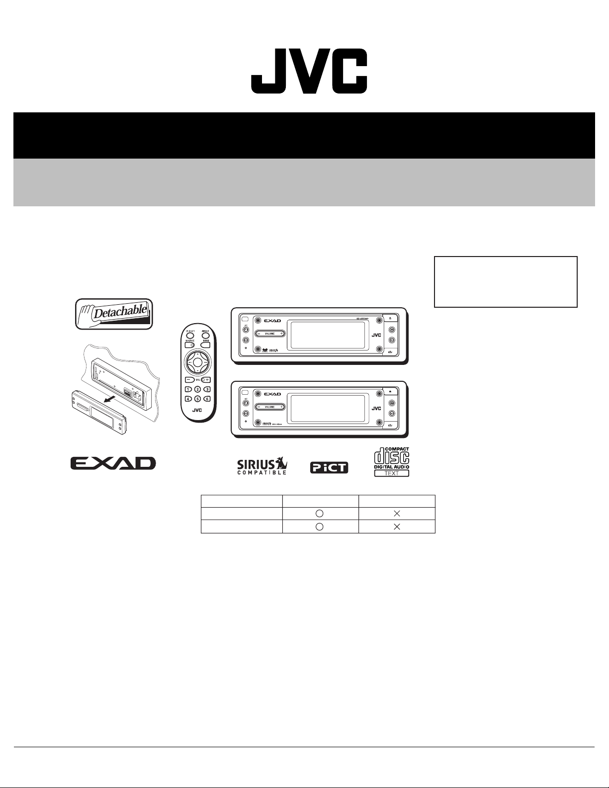
SERVICE MANUAL
CD RECEIVER
MA04320043
KD-AR5000,KD-LHX500
Area suffix
KD-AR5000
KD-LHX500
ARSENAL rogo
LINE IN
J -------------- Northern America
KD-AR5000J LHX500J
TABLE OF CONTENTS
1 PRECAUTIONS . . . . . . . . . . . . . . . . . . . . . . . . . . . . . . . . . . . . . . . . . . . . . . . . . . . . . . . . . . . . . . . . . . . . . . . 1-3
2 SPECIFIC SERVICE INSTRUCTIONS . . . . . . . . . . . . . . . . . . . . . . . . . . . . . . . . . . . . . . . . . . . . . . . . . . . . . . 1-5
3 DISASSEMBLY . . . . . . . . . . . . . . . . . . . . . . . . . . . . . . . . . . . . . . . . . . . . . . . . . . . . . . . . . . . . . . . . . . . . . . . 1-6
4 ADJUSTMENT . . . . . . . . . . . . . . . . . . . . . . . . . . . . . . . . . . . . . . . . . . . . . . . . . . . . . . . . . . . . . . . . . . . . . . . 1-27
5 TROUBLESHOOTING . . . . . . . . . . . . . . . . . . . . . . . . . . . . . . . . . . . . . . . . . . . . . . . . . . . . . . . . . . . . . . . . . 1-28
COPYRIGHT © 2004 VICTOR COMPANY OF JAPAN, LIMITED
No.MA043
2004/3
Page 2
SPECIFICATION
AUDIO AMPLIFIER SECTION
Maximum Power Output Front 50 W per channel
Rear 50 W per channel
Continuous Power Output (RMS) Front 19 W per channel into 4 Ω, 40 Hz to 20 000 Hz at no more than
0.8% total harmonic distortion.
Rear 19 W per channel into 4 Ω, 40 Hz to 20 000 Hz at no more than
0.8% total harmonic distortion.
Load Impedance 4 Ω (4 Ω to 8 Ω allowance)
Equalizer Control Range Frequencies 60 Hz, 150 Hz, 400 Hz, 1 kHz, 2.4 kHz, 6 kHz, 12 kHz
Level ±10 dB
Frequency Response 40 Hz to 20 000 Hz
Signal-to-Noise Ratio 70 dB
Line-In Level/Impedance LINE IN 1.5 V/20 kΩ load (KD-AR5000 only)
Line-Out Level/Impedance KD-AR5000 5.0 V/20 kΩ load (full scale)
KD-LHX500 4.0 V/20 kΩ load (full scale)
Output Impedance 1 kΩ
Other Terminals SUBWOOFER OUT
Changer control
TUNER SECTION
Frequency Range FM 87.5 MHz to 107.9 MHz
AM 530 kHz to 1 710 kHz
[FM Tuner] Usable Sensitivity 11.3 dBf (1.0 µV/75 Ω)
50 dB Quieting Sensitivity 16.3 dBf (1.8 µV/75 Ω)
Alternate Channel Selectivity (400 kHz) 65 dB
Frequency Response 40 Hz to 15 000 Hz
Stereo Separation 35 dB
Capture Ratio 1.5 dB
[AM Tuner] Sensitivity 20 µV
Selectivity 65 dB
CD PLAYER SECTION
Type Compact disc player
Signal Detection System Non-contact optical pickup (semiconductor laser)
Number of channels 2 channels (stereo)
Frequency Response 5 Hz to 20 000 Hz
Dynamic Range 98 dB
Signal-to-Noise Ratio 102 dB
Wow and Flutter Less than measurable limit
MP3 (MPEG Audio Layer 3) Max. Bit rate 320 Kbps
WMA (Windows Media Audio) Max. Bit rate 192 Kbps
GENERAL
Power Requirement Operating Voltage DC 14.4 V (11 V to 16 V allowance)
Grounding System Negative ground
Allowable Operating Temperature 0ºC to +40ºC (32ºF to 104ºF)
Dimensions (W × H × D) Installation Size 182 mm × 52 mm × 157.5 mm (7-3/16" × 2-1/16" × 6-1/4")
Panel Size 188 mm × 58 mm × 13 mm (7-7/16" × 2-5/16" × 9/16")
Mass 1.86 kg (4.1 lbs) (excluding accessories)
Design and specifications are subject to change without notice.
1-2 (No.MA043)
Page 3
1.1 Safety Precautions
SECTION 1
PRECAUTIONS
!
!
Burrs formed during molding may be left over on some parts of the chassis. Therefore,
pay attention to such burrs in the case of preforming repair of this system.
Please use enough caution not to see the beam directly or touch it in case of an
adjustment or operation check.
(No.MA043)1-3
Page 4
1.2 Preventing static electricity
Electrostatic discharge (ESD), which occurs when static electricity stored in the body, fabric, etc. is discharged, can destroy the laser
diode in the traverse unit (optical pickup). Take care to prevent this when performing repairs.
1.2.1 Grounding to prevent damage by static electricity
Static electricity in the work area can destroy the optical pickup (laser diode) in devices such as CD players.
Be careful to use proper grounding in the area where repairs are being performed.
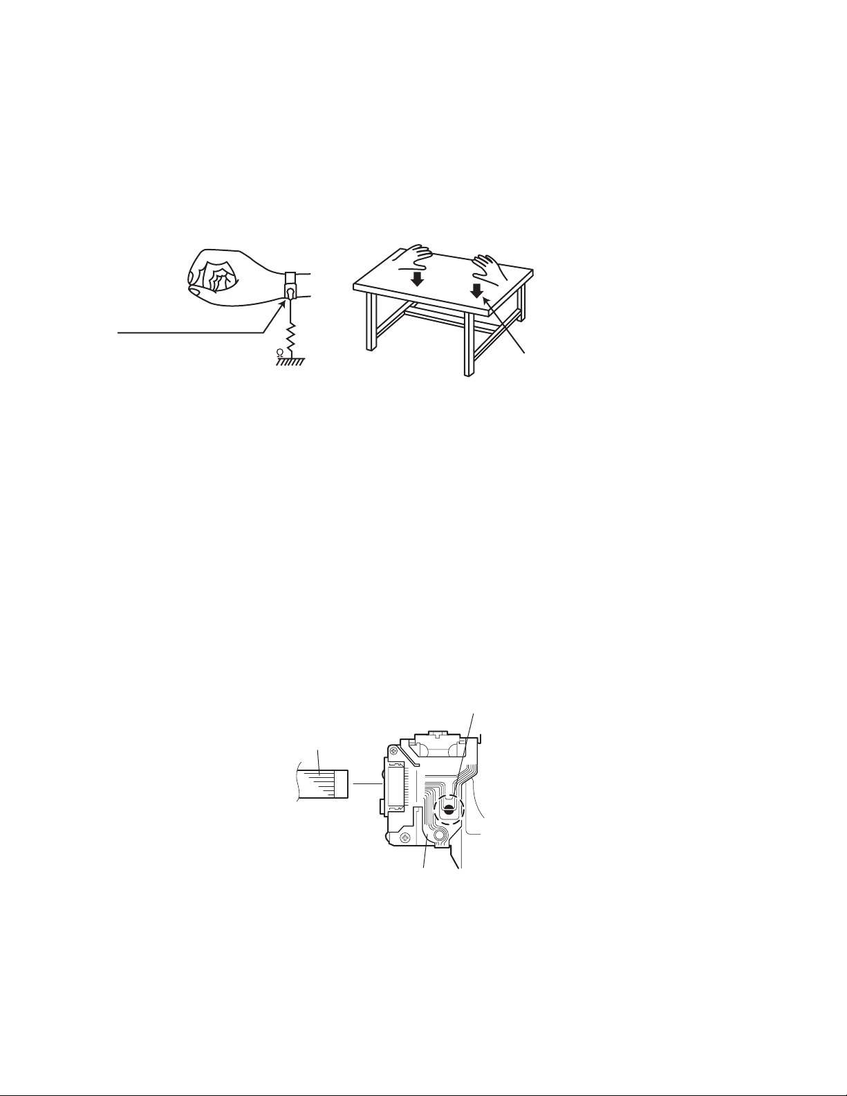
(1) Ground the workbench
Ground the workbench by laying conductive material (such as a conductive sheet) or an iron plate over it before placing the
traverse unit (optical pickup) on it.
(2) Ground yourself
Use an anti-static wrist strap to release any static electricity built up in your body.
(caption)
Anti-static wrist strap
1M
Conductive material
(conductive sheet) or iron plate
(3) Handling the optical pickup
• In order to maintain quality during transport and before installation, both sides of the laser diode on the replacement optical
pickup are shorted. After replacement, return the shorted parts to their original condition.
(Refer to the text.)
• Do not use a tester to check the condition of the laser diode in the optical pickup. The tester's internal power source can easily
destroy the laser diode.
1.3 Handling the traverse unit (optical pickup)
(1) Do not subject the traverse unit (optical pickup) to strong shocks, as it is a sensitive, complex unit.
(2) Cut off the shorted part of the flexible cable using nippers, etc. after replacing the optical pickup. For specific details, refer to the
replacement procedure in the text. Remove the anti-static pin when replacing the traverse unit. Be careful not to take too long a
time when attaching it to the connector.
(3) Handle the flexible cable carefully as it may break when subjected to strong force.
(4) It is not possible to adjust the semi-fixed resistor that adjusts the laser power. Do not turn it.
1.4 Attention when traverse unit is decomposed
*Please refer to "Disassembly method" in the text for the CD pickup unit.
• Apply solder to the short land before the flexible wire is disconnected from the connector on the CD pickup unit.
(If the flexible wire is disconnected without applying solder, the CD pickup may be destroyed by static electricity.)
• In the assembly, be sure to remove solder from the short land after connecting the flexible wire.
Short-circuit point
(Soldering)
Flexible wire
1-4 (No.MA043)
Pickup
Page 5

SECTION 2
SPECIFIC SERVICE INSTRUCTIONS
This service manual does not describe SPECIFIC SERVICE INSTRUCTIONS.
(No.MA043)1-5
Page 6
SECTION 3
DISASSEMBLY
3.1 Main body section
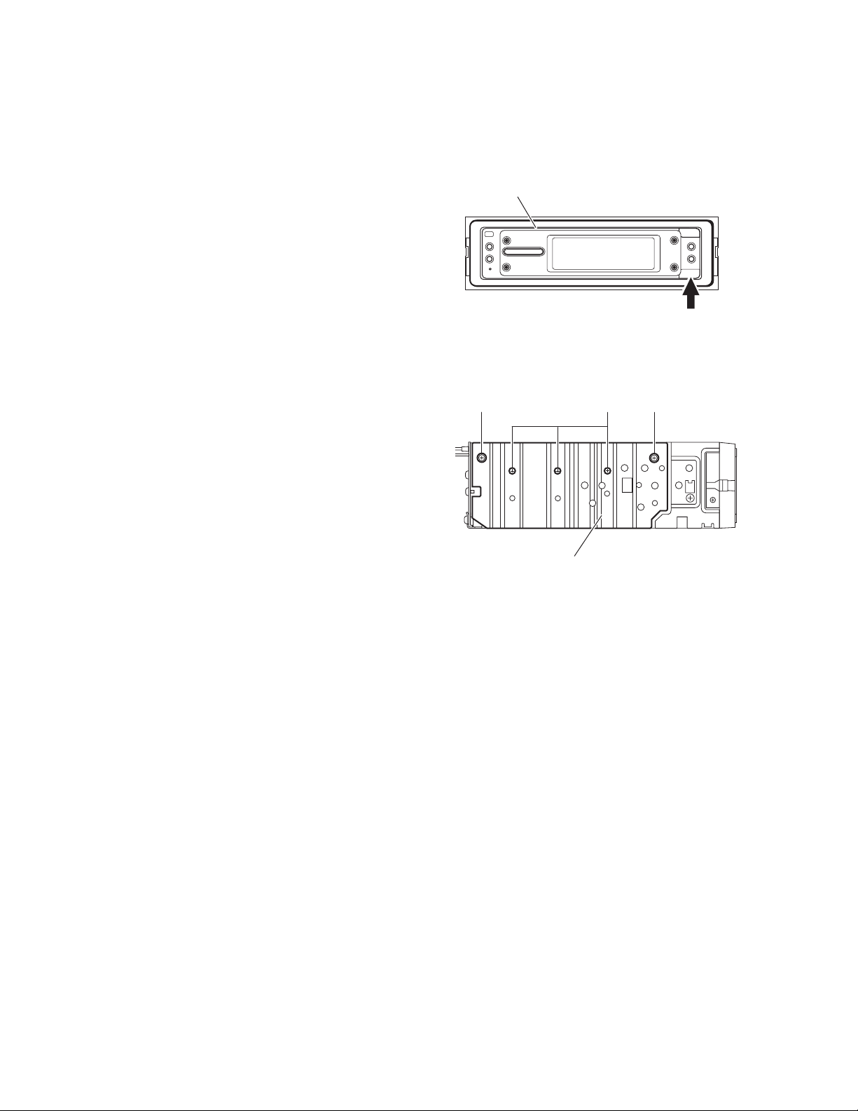
3.1.1 Removing the front panel assembly
(See Fig.1)
(1) Push the detach button in the lower right part of the front
panel assembly.
(2) Remove the front panel assembly.
3.1.2 Removing the heat sink
(See Fig.2)
(1) From the left side of the main body, remove the two screws
A and three screws B attaching the heat sink.
Front panel assembly
Detach button
Fig.1
AAB
Heat sink
Fig.2
1-6 (No.MA043)
Page 7
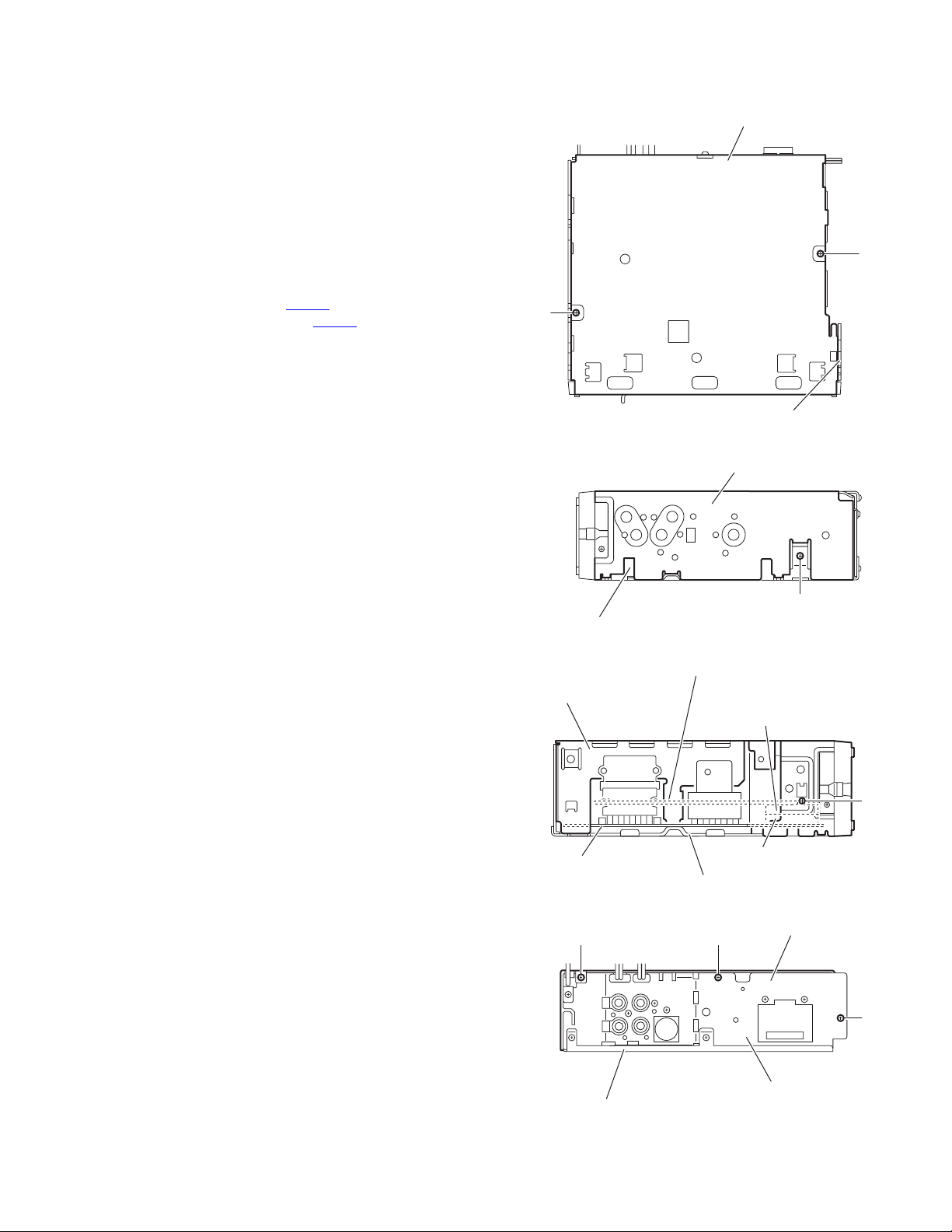
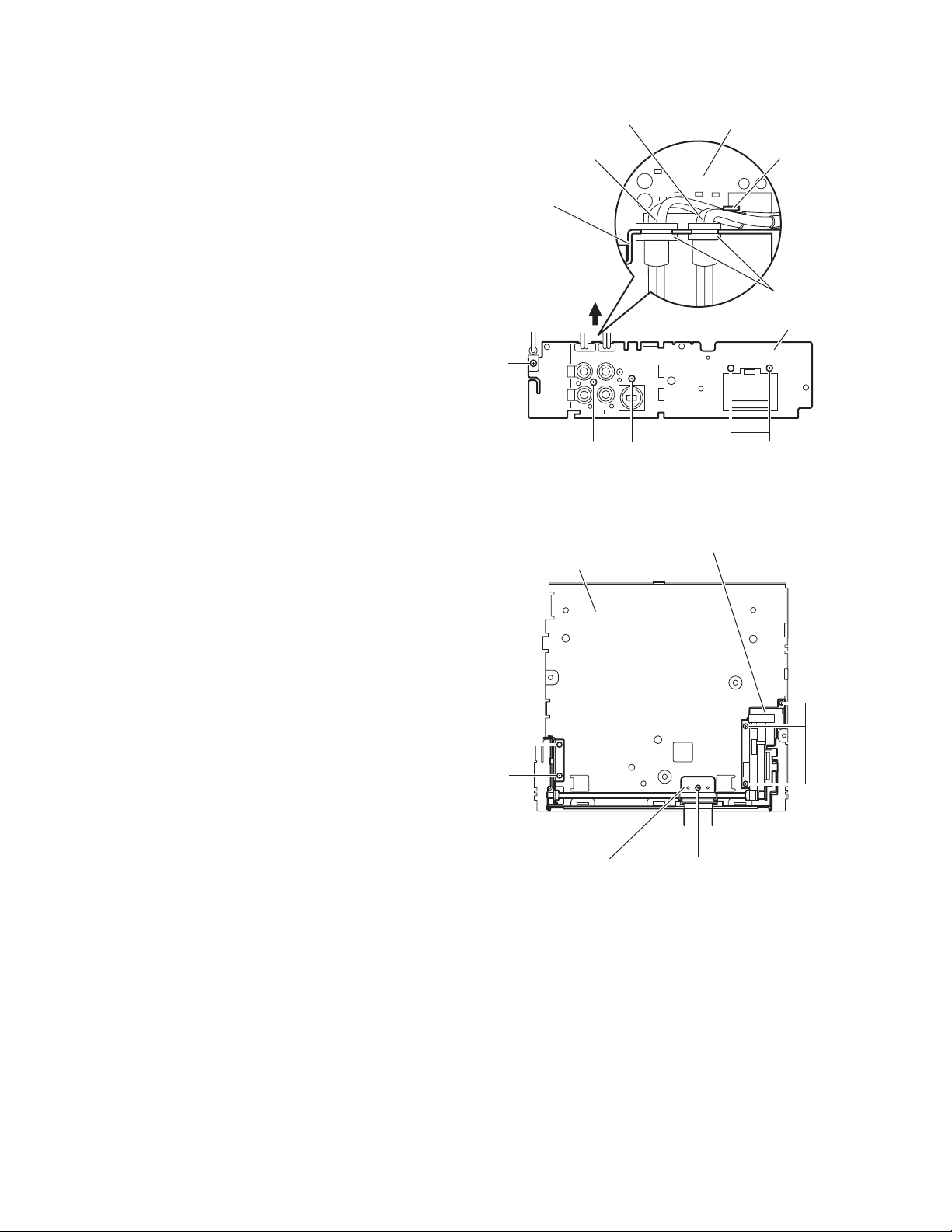
3.1.3 Removing the top chassis assembly
(See Figs.3 to 6)
• Prior to performing the following procedures, remove the heat
sink.
Reference:
Remove the front panel assembly as required.
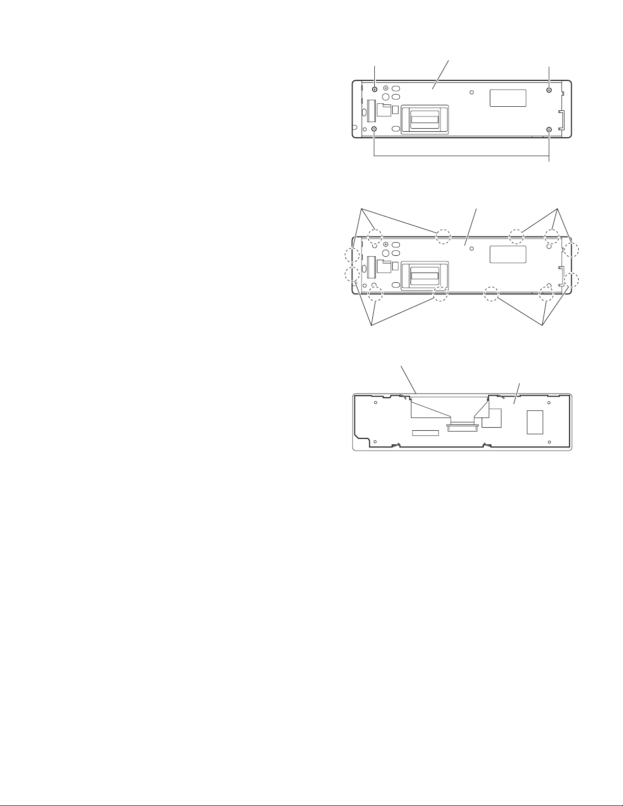
(1) From the bottom side of the main body, remove the two
screws C attaching the top chassis assembly to the bottom
chassis assembly. (See Fig.3.)
(2) From the both and rear sides of the main body, remove the
five screws D attaching the top chassis assembly to the
bottom chassis assembly. (See Figs.4 to 6.)
(3) Lift the top chassis assembly in the direction of the arrow,
disconnect the connector CN501
trol board from the connector CN702 on the main board.
(See Figs.5 and 6.)
(4) Take out the top chassis assembly from the bottom chassis
assembly.
on the mechanism con-
Bottom chassis assembly
C
C
Top chassis assembly
Fig.3
Top chassis assembly
Bottom chassis assembly
Mechanism control board
Top chassis assembly
Main board
Bottom chassis assembly
D
Fig.4
CN501
CN702
Fig.5
Top chassis assembly
D
D
D
D
Bottom chassis assembly
Rear bracket
Fig.6
(No.MA043)1-7
Page 8
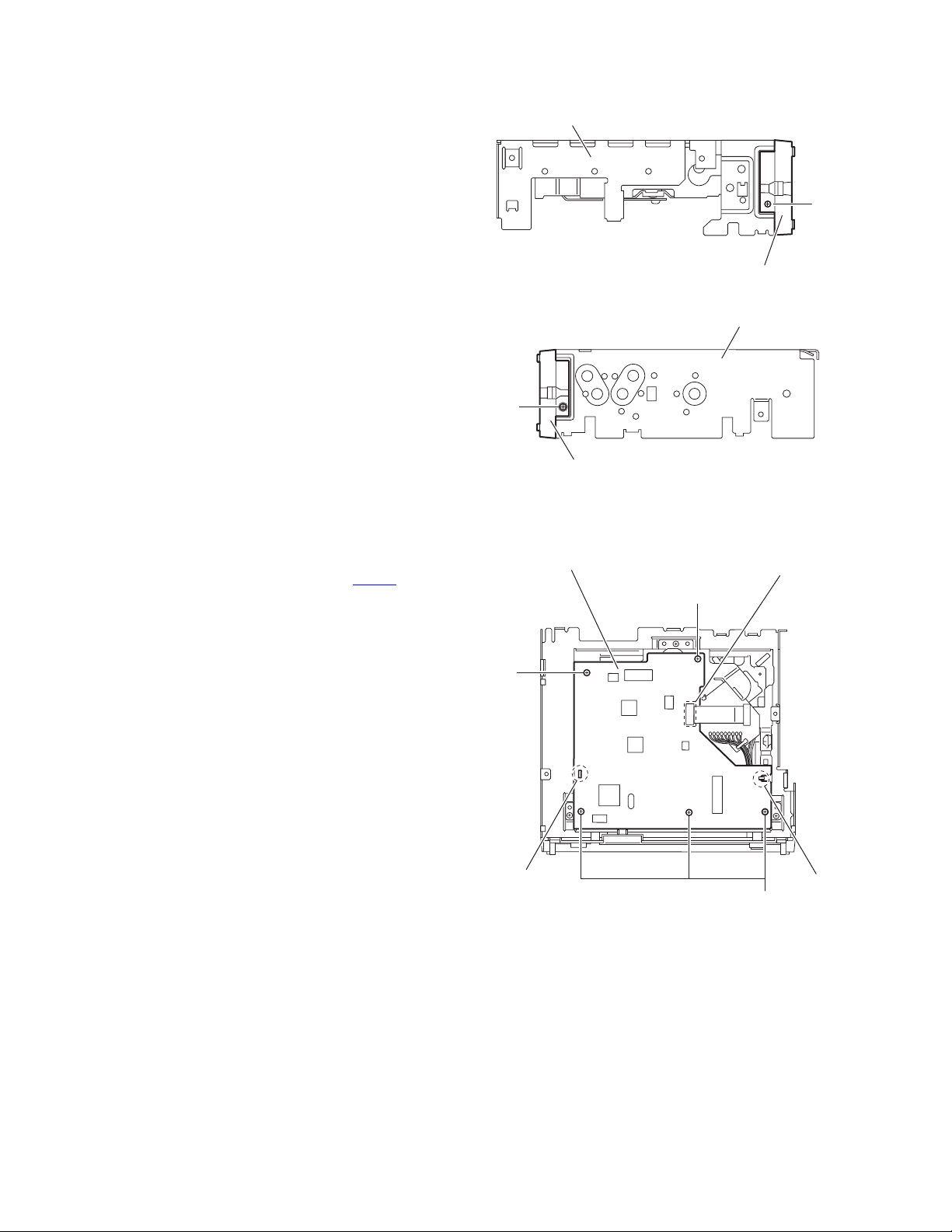
3.1.4 Removing the front chassis
(See Figs.7 and 8)
• Prior to performing the following procedure, remove the front
panel assembly, heat sink and top chassis assembly.
(1) From the both sides of the top chassis assembly, remove
the two screws E attaching the front chassis.
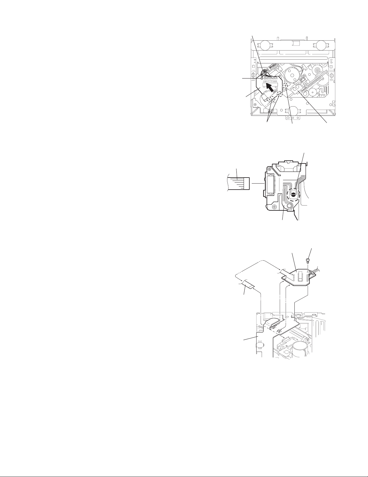
3.1.5 Removing the mechanism control board
(See Fig.9)
• Prior to performing the following procedures, remove the front
panel assembly, heat sink and top chassis assembly.
(1) Disconnect the card wire from the connector CN601
mechanism control board.
(2) Remove the five screws F attaching the mechanism control
board.
(3) Release the joints a and b, remove the mechanism control
board.
on the
Top chassis assembly
E
Front chassis
Mechanism control board
F
E
Front chassis
Fig.7
Top chassis assembly
Fig.8
CN601
F
1-8 (No.MA043)
a
b
F
Fig.9
Page 9
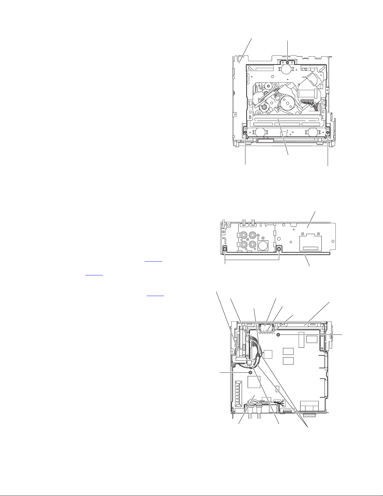
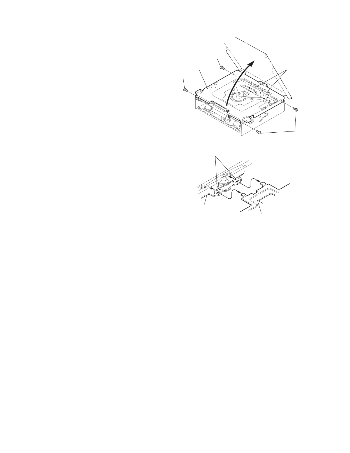
3.1.6 Removing the CD mechanism assembly (See Fig.10)
• Prior to performing the following procedures, remove the front
panel assembly, heat sink and top chassis assembly.
Reference:
Remove the mechanism control board as required.
(1) From the inside of the top chassis assembly, remove the
three screws G attaching the CD mechanism assembly.
(2) Take out the CD mechanism assembly from the top chas-
sis.
Top chassis
CD mechanism assembly
G
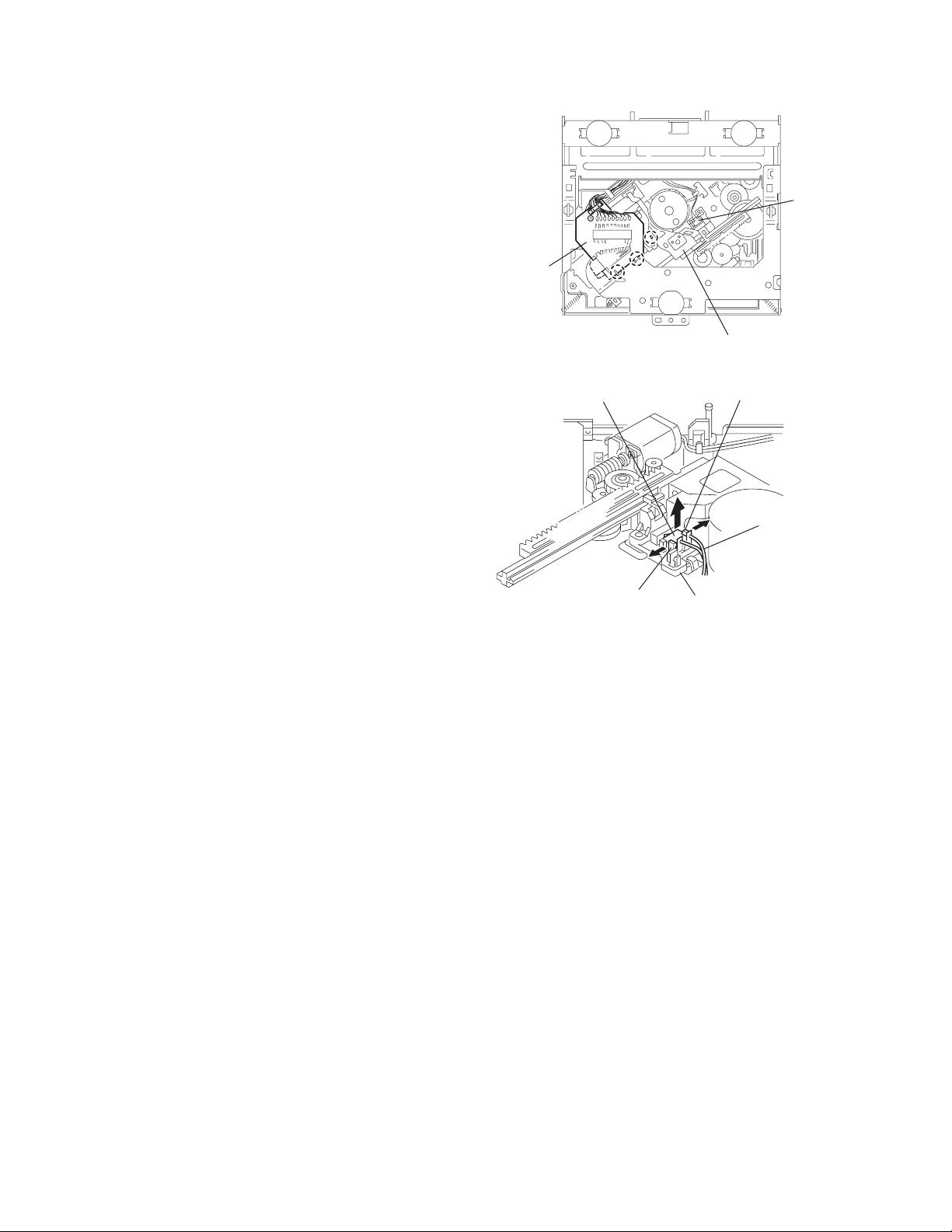
3.1.7 Removing the main board
(See Figs.11 and 12)
• Prior to performing the following procedures, remove the front
panel assembly, heat sink and top chassis assembly.
(1) From the rear side of the bottom chassis assembly, remove
the two screws H attaching the rear bracket to the bottom
chassis assembly. (See Fig.11.)
(2) From the top side of the bottom chassis assembly, remove
the two screws J attaching the main board to the bottom
chassis assembly. (See Fig.12.)
(3) Release the stopper of the connector CN701
board in an upward direction, disconnect the card wire from
the connector CN701. (See Fig.12.)
(4) Disconnect the wire from the connector of the front door
mechanism assembly. (See Fig.12.)
(5) Disconnect the wire from the connector CN991
board. (See Fig.12.)
Reference:
After connecting the wires, fix the wires with the wire
holders.
(6) Take out the main board from the bottom chassis assem-
bly.
on the main
on the main
G
Fig.10
H
Fig.11
Front door mechanism assembly
Connector
Wire holder
Card wire
CN701
G
Rear bracket
Bottom chassis assembly
Bottom chassis assembly
Stopper
J
J
Main board
CN991
Fig.12
Wires
(No.MA043)1-9
Page 10
3.1.8 Removing the rear bracket
(See Fig.13)
• Prior to performing the following procedures, remove the front
panel assembly, heat sink, top chassis assembly and main
board.
(1) From the rear side of the main board, remove the wires
from the rear bracket in the direction of the arrow.
(2) Remove the two screws K and three screws L attaching the
rear bracket to the main board.
Reference:
After attaching the rear bracket to the main board, pass the
wires through the wire holder and insert them into the slots of
the rear bracket.
Wire (KD-AR5000)
Rear bracket
K
Wire
Main board
Wire holder
Slots
Rear bracket
3.1.9 Removing the front door mechanism assembly
(See Fig.14)
• Prior to performing the following procedures, remove the front
panel assembly, heat sink, top chassis assembly and main
board.
(1) From the top side of the bottom chassis assembly, remove
the screw M attaching the shaft holder to the bottom chassis.
(2) Remove the five screws N attaching the front door mecha-
nism assembly to the bottom chassis.
Reference:
When attaching the screws M and N, apply a locking
agent them.
(3) Take out the front door mechanism assembly from the bot-
tom chassis.
Bottom chassis
N
L K
Shaft holder
L
Fig.13
Front door mechanism assembly
N
M
Fig.14
1-10 (No.MA043)
Page 11
3.1.10 Removing the front board
(See Figs.15 to 17)
• Prior to performing the following procedures, remove the front
panel assembly.
(1) From the rear side of the front panel assembly, remove the
four screws P attaching the rear cover assembly to the front
panel assembly. (See Fig.15.)
(2) Release the twelve joints c of the front panel assembly and
remove the rear cover assembly. (See Fig.16.)
(3) Take out the front board from the front panel assembly.
(See Fig.17.)
P
Rear cover assembly
P
P
Fig.15
joints c joints c
joints c joints c
Front panel assembly
Rear cover assembly
Fig.16
Fig.17
Front board
(No.MA043)1-11
Page 12
3.2 CD Mechanism section
A
3.2.1 Removing the top cover
(See Figs.1 and 2)
(1) Remove the four screws A on the both side of the body.
(2) Lift the front side of the top cover and move the top cover
backward to release the two joints a.
Top cover
Joints a
A
Joints a
A
Fig.1
Fig.2
Top cover
1-12 (No.MA043)
Page 13
3.2.2 Removing the connector board
(See Figs.3 to 5)
CAUTION:
Before disconnecting the flexible wire from the pickup, solder
the short-circuit point on the pickup. No observance of this instruction may cause damage of the pickup.
(1) Remove the screw B fixing the connector board.
(2) Solder the short-circuit point on the pickup.
(3) Disconnect the flexible wire from the pickup.
(4) Move the connector board in the direction of the arrow to
release the two joints b.
(5) Unsolder the wires on the connector board if necessary.
CAUTION:
Unsolder the short-circuit point after reassembling.
B
Connector board
Flexible wire
Wires
Joints b
Short-circuit point
Fig.3
Short-circuit point
(Soldering)
Pickup
Flexible wire
Frame
Pickup
Fig.4
B
Connector board
Fig.5
(No.MA043)1-13
Page 14
3.2.3 Removing the DET switch
(See Figs.6 and 7)
(1) Extend the two tabs c of the feed sw. holder and pull out
the switch.
(2) Unsolder the DET switch wire if necessary.
DET
switch
Connector
board
Pickup
Fig.6
DET switch
Tab c
Tab c
DET switch wire
Feed sw. holder
Fig.7
1-14 (No.MA043)
Page 15

3.2.4 Removing the chassis unit
r
(See Figs.8 and 9)
• Prior to performing the following procedure, remove the top
cover and connector board.
(1) Remove the two suspension springs (L) and (R) attaching
the chassis unit to the frame.
CAUTION:
• The shape of the suspension spring (L) and (R) are different. Handle them with care.
• When reassembling, make sure that the three shafts
on the underside of the chassis unit are inserted to the
dampers certainly.
Suspension spring (R)
Chassis unit
Suspension spring (L)
Frame
Suspension spring (R)
Chassis unit
Shafts
Damper
Damper
Suspension spring (L)
Fig.8
Shaft
Dampe
Frame
Fig.9
(No.MA043)1-15
Page 16

3.2.5 Removing the clamper assembly
(See Figs.10 and 11)
• Prior to performing the following procedure, remove the top
cover.
(1) Remove the clamper arm spring.
(2) Move the clamper assembly in the direction of the arrow to
release the two joints d.
Clamper arm
spring
Joint d
Joint d
Clamper assembly
Fig.10
Clamper arm spring
Chassis rivet
assembly
Joint d
Clamper assembly
Chassis rivet assembly
Joint d
Fig.11
1-16 (No.MA043)
Page 17

3.2.6 Removing the loading / feed motor assembly
(See Figs.12 and 13)
• Prior to performing the following procedure, remove the top
cover, connector board and chassis unit.
(1) Remove the screw C and move the loading / feed motor as-
sembly in the direction of the arrow to remove it from the
chassis rivet assembly.
(2) Disconnect the wire from the loading / feed motor assembly
if necessary.
CAUTION:
When reassembling, connect the wire from the loading /
feed motor assembly to the flame as shown in Fig.12.
Loading / feed motor assembly
Fig.12
Loading / feed motor assembly
C
Fig.13
(No.MA043)1-17
Page 18

3.2.7 Removing the pickup unit
r
(See Figs.14 to 18)
• Prior to performing the following procedure, remove the top
cover, connector board and chassis unit.
(1) Remove the screw D and pull out the pu. shaft holder from
the pu. shaft.
(2) Remove the screw E attaching the feed sw. holder.
(3) Move the part e of the pickup unit upward with the pu. shaft
and the feed sw. holder, then release the joint f of the feed
sw. holder in the direction of the arrow. The joint g of the
pickup unit and the feed rack is released, and the feed sw.
holder comes off.
(4) Remove the pu. shaft from the pickup unit.
(5) Remove the screw F attaching the feed rack to the pickup
unit.
3.2.8 Reattaching the pickup unit
(See Figs.14 to 17)
(1) Reattach the feed rack to the pickup unit using the screw F.
(2) Reattach the feed sw. holder to the feed rack while setting
the joint g to the slot of the feed rack and setting the joint f
of the feed rack to the switch of the feed sw. holder correctly.
(3) As the feed sw. holder is temporarily attached to the pickup
unit, set to the gear of the joint g and to the bending part of
the chassis (joint h) at a time.
CAUTION:
Make sure that the part i on the underside of the feed
rack is certainly inserted to the slot j of the change lock
lever.
(4) Reattach the feed sw. holder using the screw E.
(5) Reattach the pu. shaft to the pickup unit. Reattach the pu.
shaft holder to the pu. shaft using the screw D.
Part e
Joint g
Feed sw. holder
Feed rack
Part i
E
Slot j
F
Fig.15
Pu. shaft
Pickup unit
Joint f
Joint h
Fig.16
Feed rack
Pickup unit
Feed sw. holder
D
Pu. shaft holde
Joint f
Pu. shaft
D
Pu. shaft holder
Feed sw. holder
Pickup unit
Fig.14
Part e
E
Joint g
Pickup unit
Feed rack
Fig.17
Pickup unit
Joint g
Joint f
Feed sw. holder
Fig.18
1-18 (No.MA043)
Page 19

3.2.9 Removing the trigger arm
r
(See Figs.19 and 20)
• Prior to performing the following procedure, remove the top
cover, connector board and clamper unit.
(1) Turn the trigger arm in the direction of the arrow to release
the joint k and pull out upward.
CAUTION:
When reassembling, insert the part m and n of the trigger
arm into the part p and q at the slot of the chassis rivet
assembly respectively and join the joint k at a time.
Chassis rivet assembly
Trigger arm
Chassis
rivet
assembly
Joint k
Trigger arm
Fig.19
Part p
Part q
Part m
Part n
3.2.10 Removing the top plate assembly
(See Fig.21)
• Prior to performing the following procedure, remove the top
cover, connector board, chassis unit, and clamper assembly.
(1) Remove the screw H.
(2) Move the top plate assembly in the direction of the arrow to
release the two joints r.
(3) Unsolder the wire marked s if necessary.
H
Fig.20
Top plate assembly
Joints
s
Fig.21
(No.MA043)1-19
Page 20

3.2.11 Removing the mode sw. / select lock arm
(See Figs.22 and 23)
• Prior to performing the following procedure, remove the top
plate assembly.
(1) Bring up the mode sw. to release from the link plate (joint t)
and turn in the direction of the arrow to release the joint u.
(2) Unsolder the wire of the mode sw. marked s if necessary.
(3) Turn the select lock arm in the direction of the arrow to re-
lease the two joints v.
(4) The select lock arm spring comes off the select lock arm at
the same time.
Link plate
Joint u
Fig.22
Joint t
Mode sw.
Select lock arm
s
Top plate
Select lock arm
Link plate
Select lock arm
Fig.23
Top plate
Hook w
Select lock
arm spring
Joints v
1-20 (No.MA043)
Page 21

3.2.12 Reassembling the mode sw. / select lock arm
(See Figs.24 to 26)
REFERENCE:
Reverse the above removing procedure.
(1) Reattach the select lock arm spring to the top plate and set
the shorter end of the select lock arm spring to the hook w
on the top plate.
(2) Set the other longer end of the select lock arm spring to the
boss x on the underside of the select lock arm, and join the
select lock arm to the slots (joint v). Turn the select lock
arm as shown in the figure.
(3) Reattach the mode sw. while setting the part t to the first
peak of the link plate gear, and join the joint u.
CAUTION:
When reattaching the mode sw., check if the points y and
z are correctly fitted and if each part operates properly.
Select lock arm spring
Hook w
Joint v
Joint v
Select lock arm
Boss x
Fig.24
Joint t
Point y
Link plate
Point z
Link plate
Fig.25
Mode sw.
Select
lock arm
Joint t
Joint u
Fig.26
(No.MA043)1-21
Page 22

3.2.13 Removing the select arm R / link plate
(See Figs.27 and 28)
• Prior to performing the following procedure, remove the top
plate assembly.
(1) Bring up the select arm R to release from the link plate
(joint a') and turn as shown in the figure to release the two
joints b' and joint c'.
(2) Move the link plate in the direction of the arrow to release
the joint d'. Remove the link plate spring at the same time.
REFERENCE:
Before removing the link plate, remove the mode sw..
Select arm R
Joint b'
Link plate spring
Joint c'
Joint a'
Link plate
Joint b'
Fig.27
Joint r
3.2.14 Reattaching the Select arm R / link plate
(See Figs.29 and 30)
REFERENCE:
Reverse the above removing procedure.
(1) Reattach the link plate spring.
(2) Reattach the link plate to the link plate spring while joining
them at joint d'.
(3) Reattach the joint a' of the select arm R to the first peak of
the link plate while joining the two joints b' with the slots.
Then turn the select arm R as shown in the figure. The top
plate is joined to the joint c'.
CAUTION:
When reattaching the select arm R, check if the points e'
and f' are correctly fitted and if each part operates properly.
Top plate
Select arm R
Joint b'
Joint d'
Link plate
Fig.28
Link plate spring
Joint c'
Joint d'
Joint b'
Joint a'
Fig.29
1-22 (No.MA043)
Joint a'
Point e'
Link plate
Point f'
Fig.30
Page 23

3.2.15 Removing the loading roller assembly
(See Figs.31 to 33)
• Prior to performing the following procedure, remove the
clamper assembly and top plate assembly.
(1) Push inward the loading roller assembly on the gear side
and detach it upward from the slot of the joint g' of the lock
arm rivet assembly.
(2) Detach the loading roller assembly from the slot of the joint
h' of the lock arm rivet assembly.
The roller guide comes off the gear section of the loading
roller assembly.
Remove the roller guide and the HL washer from the shaft
of the loading roller assembly.
(3) Remove the screw J attaching the lock arm rivet assembly.
(4) Push the shaft at the joint i' of the lock arm rivet assembly
inward to release the lock arm rivet assembly from the slot
of the L side plate.
(5) Extend the lock arm rivet assembly outward and release
the joint j' from the boss of the chassis rivet assembly. The
roller guide springs on both sides come off at the same
time.
CAUTION:
When reassembling, reattach the left and right roller
guide springs to the lock arm rivet assembly before reattaching the lock arm rivet assembly to the chassis rivet
assembly. Make sure to fit the part k' of the roller guide
spring inside of the roller guide. (Refer to Fig.34.)
Roller guide
spring
Part k'
Chassis rivet assembly
Loading roller assembly
Loading roller assembly
Roller guide
spring
Fig.32
Boss
Roller guide
Joint h'
Roller guide spring
Loading roller assembly
HL washer
Loading roller assembly
Joint g'
Lock arm rivet assembly
Fig.31
Roller guide
Roller guide spring
Roller guide spring
J
Lock arm rivet assembly
Lock arm rivet assembly
L side plate
Roller guide spring
Joint i'
Joint j'
Fig.33
Roller guide
HL washer
Roller shaft assembly
Loading roller
Roller guide spring
Fig.34
(No.MA043)1-23
Page 24

3.2.16 Removing the loading gear 5, 6 and 7
(See Figs.35 and 36)
• Prior to performing the following procedure, remove the top
cover, chassis unit, pickup unit and top plate assembly.
(1) Remove the screw K attaching the loading gear bracket.
The loading gear 6 and 7 come off the loading gear bracket.
(2) Pull out the loading gear 5.
K
Loading gear 5
Loading gear bracket
K
Loading gear 6
Loading gear 5
Loading gear 3
Fig.35
Loading gear bracket
Loading gear 6
Loading gear 7
Fig.36
1-24 (No.MA043)
Page 25

3.2.17 Removing the gears
(See Figs.37 to 40)
• Prior to performing the following procedure, remove the top
cover, chassis unit, top plate assembly and pickup unit.
• Pull out the loading gear 3. (See Fig.35.)
(1) Pull out the feed gear.
(2) Move the loading plate assembly in the direction of the ar-
row to release the L side plate from the two slots m' of the
chassis rivet assembly. (See Fig.37.)
(3) Detach the loading plate assembly upward from the chas-
sis rivet assembly while releasing the joint n'. Remove the
slide hook and loading plate spring from the loading plate
assembly.
(4) Pull out the loading gear 2 and remove the change lock le-
ver.
(5) Remove the E ring and washer attaching the change gear
2.
(6) The change gear 2, change gear spring and adjusting
washer come off.
(7) Remove the loading gear 1.
(8) Move the change plate rivet assembly in the direction of the
arrow to release from the three shafts of the chassis rivet
assembly upward. (See Fig.38.)
(9) Detach the loading gear plate rivet assembly from the shaft
of the chassis rivet assembly upward while releasing the
joint p'. (See Figs.38 and 40.)
(10) Pull out the loading gear 4.
Change plate
rivet assembly
Shafts
E ring
Loading plate assembly
Loading plate spring
Joint p'
Loading gear 4
Loading gear plate
rivet assembly
Shaft
Loading gear 2
Loading gear 1
Chassis rivet assembly
Change gear 2
Fig.38
Joint n'
Slide hook
Feed gear
Fig.37
Slot m'
L side plate
Loading plate assembly
Joint n'
Slot m'
Chassis rivet assembly
Chassis rivet assembly
E ring
Washer
Change gear 2
Change gear
spring
Adjusting
washer
Change plate
rivet assembly
L side plate
Slot m'
Slot m'
Fig.39
Loading gear 1
Loading gear 2
Change lock lever
Loading gear 4
Chassis rivet assembly
Loading gear plate rivet
assembly
Fig.40
(No.MA043)1-25
Page 26

3.2.18 Removing the turn table / spindle motor
(See Figs.41 and 42)
• Prior to performing the following procedure, remove the top
cover, connector board, chassis unit and clamper assembly.
(1) Remove the two screws L attaching the spindle motor as-
sembly through the slot of the turn table on top of the body.
(2) Unsolder the wire on the connector board if necessary.
Turn table
L
Fig.41
L
Turn table
1-26 (No.MA043)
Spindle motor
Fig.42
Page 27

SECTION 4
ADJUSTMENT
4.1 Adjustment method
Test instruments required for adjustment
(1) Digital oscilloscope (100MHz)
(2) Electric voltmeter
(3) Digital tester
(4) Tracking offset meter
(5) Test Disc JVC :CTS-1000
(6) Extension cable for check
EXTSH002-22P × 1
Standard volume position
Balance and Bass &Treble volume : lndication"0"
Loudness : OFF
How to connect the extension cable for adjusting
Caution:
Be sure to attach the heat sink and rear bracket onto the power amplifier IC and regulator IC respectively, before supply the power.
If voltage is applied without attaching these parts, the power amplifier IC and regulator IC will be destroyed by heat.
Standard measuring conditions
Power supply voltage DC14.4V(10.5 to 16V)
Load impedance 20KΩ(2 Speakers connection)
Output Level Line out 2.0V (Vol. MAX)
Dummy load
Exclusive dummy load should be used for AM,and FM. For FM
dummy load,there is a loss of 6dB between SSG output and
antenna input.The loss of 6dB need not be considered since
direct reading of figures are applied in this working standard.
Extension cable: EXTSH002-22P
Heat sink
Rear bracket
(No.MA043)1-27
Page 28

5.1 Feed section
SECTION 5
TROUBLESHOOTING
Is 5v or 0V at IC621
pin 40?
YES
Is 4V present at both
sides of the feed motor?
YES
Check the feed motor.
5.2 Focus section
5.3 Spindle section
NO
Is the wiring for IC621
pin 40 correct?
NO
Is 6V or 2V present at
IC681 pins 17 and 18?
Check IC681.
When the lens is
moving:
Does the S-search
waveform appear at
IC681 pins 13 and 14?
NO
NO
YES
4V
YES
YES
Is 5V present at IC681
pin 6?
Check the vicinity of
IC621.
Check the feed motor
connection wiring.
NO
Check the circuits in
the vicinity of IC681
pins 1 and 2.
Check the pickup and
its connections.
NO
Check CD8V.
YES
YES
Is the disk rotated?
YES
Does the RF signal
appear at IC601 pin 19?
YES
Is the RF waveform
at IC601 pin 19 distorted?
YES
Proceed to the Tracking
section
5.4 Tracking section
When the disc is rotated
at first:
Is the tracking error
signal output at IC601
pin 11?
NO
Is 4V present between
IC681 pins 15 and 16?
Check the spindle motor
and its wiring.
NO
Check the circuits in
the vicinity of IC601
or the pickup.
NO
NO
Approx. 1.2V
YES
NO
YES
Check the circuits in
the vicinity of IC601
pins 2 to 12.
Is 4V present at IC621
pin 41?
YES
Check the vicinity of
IC681.
NO
Check the pickup and
its connections.
NO
Check IC621.
1-28 (No.MA043)
Check IC621.
Page 29

5.5 Signal processing section
Is the sound output from
both channels (L, R)?
YES
Normal
NO
No sound from either
channel.
Is 9V present at IC365
pin 16?
Is the audio signal
(including sampling
output components)
output to IC191/IC291
pins 1 and 7 during
playback?
Is the audio signal output
at IC171/IC271 pins 12
and 13 during playback?
YES
YES
YES
Compare the L-ch and
NO
R-ch to locate the
defective point.
NO
Is 9V present at IC901
pin 10?
Check the connection
between IC901 pin10
and IC365 pin 16.
NO
Check IC191/IC291 and
its peripheral circuits.
NO
Check IC171/IC271 and
its peripheral circuits.
YES
NO
Check IC901 and its
peripheral circuits.
YES
Check the power amp.
IC951.
(No.MA043)1-29
Page 30

5.6 Maintenance of laser pickup
(1) Cleaning the pick up lens
Before you replace the pick up, please try to clean the lens
with a alcohol soaked cotton swab.
(2) Life of the laser diode
When the life of the laser diode has expired, the following
symptoms will appear.
• The level of RF output (EFM output: amplitude of eye
pattern) will be low.
5.7 Replacement of laser pickup
Turn of the power switch and, disconnect the
power cord.
Replace the pickup with a normal one. (Refer
to "Removing the pickup unit" on the previous page.)
Is RF output
1.3 0.4Vp-p?
NO
Replace it.
YES
OK
(3) Semi-fixed resistor on the APC PC board
The semi-fixed resistor on the APC printed circuit board
which is attached to the pickup is used to adjust the laser
power.Since this adjustment should be performed to match
the characteristics of the whole optical block, do not touch
the semi-fixed resistor.
If the laser power is lower than the specified value, the laser diode is almost worn out, and the laser pickup should
be replaced. If the semi-fixed resistor is adjusted while the
pickup is functioning normally, the laser pickup may be
damaged due to excessive current.
Plug the power cord in, and turn the power on.
At this time, check that the laser emits for about
seconds and the objective lens moves up and down.
Note: Do not observe the laser beam directly.
Play a disc.
Check the eye-pattern at
RF test point.
Finish.
1-30 (No.MA043)
Page 31

5.8 Service mode
5.8.1 Service mode setting
(1) Push POWER BOTTON (Power ON)
(2) Set to service mode
By pushing and holding "DISP" + "VOLUME +" + touch panel "upper right" sequentially.
"VOLUME +" button
SERVICE MODE3 (MENU)
PRODUCT
DSP TUNER
MODE
S MODE
SERVICE
MODE
DSP TUNER
Adjust
RUNNING
MODE
VOICE
CHECK
SERVICE MODE (MENU)
2
St
1:37
TUNER
No Name
87.5
-P
TOUCH PANEL
DATA
CLEAR
BACK
VERSION CD DATA
ROM COLLE
READ
NON
"DISP" button
P+
FLAT
MHz
FM1
12
5
6748
ERR READ
BACK
VERSION
VERSION
MAIN
CD V
CH V
CD DATA READ (MENU)
ADJ NOW ADJ INIT OTHERS
3
****
X
DSP
Y
V
Version display
V
* Termal AD value
Panel microcom version display
Display ROM version display
BACK
BACK
CD ERROR READ (MENU)
CD ERR
TDSP ERR
CH ERR MECHA ERR
BACK
CD ERROR
CD ERR
******
******
******
******
2
3
4
5
E1
E2
E3
1
CH ERROR
CH ERR
******
******
******
******
2
3
4
5
E1
E2
E3
1
******
******
******
******
******
******
******
******
CD error display
* Display by error code chart
BACK
CD changer error display
* Display by error code chart
BACK
MECHA ERROR
MECHA ERR
******
2
******
******
******
3
4
5
******
******
******
******
E1
E2
E3
1
DSP TUNER ERROR
TDSP ERROR
RETRY
RETRY NG
A
B
TOTAL
TOTAL
***
***
Door mecha error display
* Display by error code chart
BACK
DSP tuner error display
* The number of times of the
communication error at the time of
Power ON is displayed.
BACK
(No.MA043)1-31
Page 32

A
B
ROM COLLECTION
DATA
READ
DATA
CLEAR
Don't used
BACK
DATA READ (No disc)
PLEASE INSERT
DATA CD
BACK
DATA READING
NOW . . .
DATA CLEAR
DON'T TOUCH ANY KEY
SUCCESS
SUCCESS!!
***
VER
PLEASE EJECT CD
Return to normal display
FALL
five seconds after
FALL
PLEASE EJECT CD
RUNNING1 MODE(MENU)
RUNNING1
3
MECHA
RUNNING2
MECHA
DATA CLEAR (MENU)
EPROM
CLEAR
4
CH ERROR
CLEAR
NAME
CLEAR
MECHA ERR
CLEAR
RUNNING3
MECHA
BACK
RUNNING1 MECHA
RUNNING1
Count
Error
RUNNING2 MECHA
RUNNING2
Count
Error
RUNNING3 MECHA
RUNNING3
Count
Error
CD ERROR
CLEAR
PICTURE
CLEAR
BACK
MECHA
MECHA
MECHA
DATA CLEAR
NOW . . .
DATA CLEAR
BACK
Running mode1
Running count
Door error during running mode
by error code chart
BACK
Running mode2
Running count
Door error during running mode
by error code chart
BACK
Running mode3
Running count
Door error during running mode
by error code chart
BACK
Return to normal display
Don't clear
Return to normal display
five seconds after
five seconds after
C
1-32 (No.MA043)
EPROM CLEAR
EPROM all clear & Flash ROM all clear
NOW . . .
EPROM CLEAR
(Following all contents are cleared.)
BACK
NAME CLEAR
NOW . . .
NAME CLEAR
D
EPROM (DISC NAME) clear
BACK
Page 33

C
D
CD ERROR CLEAR
NOW . . .
CD ERROR CLEAR
EPROM (CD ERROR) clear
Error code history elimination
BACK
CH ERROR CLEAR
EPROM (CH ERROR) clear
NOW . . .
CH ERROR CLEAR
Error code history elimination
BACK
MECHA ERROR CLEAR
EPROM ( MECHA ERROR) clear
NOW . . .
MECHA ERR CLEAR
Error code history elimination
BACK
PICTURE CLEAR
NOW . . .
FM DATA(FM:Standard)
FM DATA
5
EEPROM
VIEW
VER=J021
87.5 MHz SM= 0%
MP=100%
A
dj
= 49%
BW=5
AM DATA (AM: Common )
VER=J021
87.5 MHz SM= 0%
MP=100%
A
dj
= 49%
BW=5
DSP TUNER SERVICE MODE (FM:RDS) (MENU)
VER=J021
87.5 MHz SM= 0%
MP=100%
dj
= 49%
A
BW=5
FM received
Without RDS model
BACK
FM received
BACK
AM received
BACK
FM received
Only used RDS model
BACK
RDS_DATA
****
SPI=
***
***.**
*******
**
EON
*
STREO
*
VER= V
PI=
PTY=
TP/TA= */
MS/DI= */
RDS_AF
AF
****.**
;
****.**
****.**
****.**
****.**
,
****.**
,
****.**
,
****.**
RDS_AFHOLD
MF=
***.**
AF=
Flags
SM=
MP=
Adj=
***
***
***
PI=
%
SM=
MP=
%
%
Adj=
PICTURE CLEAR
***
SM=
***
MHz
MP=
***
dj
=
***
A
*
BW=
****.**
;
****.**
,
****.**
,
****.**
,
***.**
SM= 0%
****
MP=100%
***
%
dj
= 49%
A
***
%
BW=5
***
%
EPROM ROM (all PICTURE) clear
BACK
ONLY USED WITH RDS MODEL
%
%
%
;
,
,
,
Only used RDS model
BACK
It is made to scroll upwards
for every second.
BACK
BACK
RDS_ENGINEER
SYNC
PIC
=
*
=
STTH1
SMTH2
******
=
=
MORE
Adj
SM L
******
=
=
SMM1
SSM2
******
=
=
E
F
*****
******
******
******
AFC
=
Mp
=
*****
******
MORE
MORE
BACK
MORE
BACK
For the reason for production,
please do not choose with service.
Operation will become unusual if
an unsuitable setup is carried out.
G
(No.MA043)1-33
Page 34

E
F
EPROM VIEW
EPROM
** ** ** ** ** ** ** **
** ** ** ** ** ** ** **
** ** ** **
BACK
G
RDS_ENGINNER (ADJUST)
SYNC
SYNC
=
*
Default
Enter
BACK
PIC
PIC
=
*****
Default
Enter
BACK
AFC
AFC
=
*****
Default
Enter
BACK
SMITH1
SMITH
=
******
Default
Enter
BACK
SMITH2
SMITH2
******
=
Mp
Mp
******
=
Adj
Adj
=
******
SM L
SM L
******
=
SMM1
SMM1
******
=
SMM2
SMM2
=
******
Default
Default
Default
Default
Default
Default
Enter
BACK
Enter
BACK
Enter
BACK
Enter
BACK
Enter
BACK
Enter
H
1-34 (No.MA043)
BACK
ONLY USED WITH RDS MODEL
Page 35

H
AUTO ADJ
MANUAL ADJ
AUTO ADJ
It is not used for the item used inside at the time of manufacture.
AUTO ADJ
1
87.5MHz
FM DAA
40dBuV 0%
BACK
AUTO ADJ
1
87.5MHz
FM DAA
40dBuV 0%
No Signal
BACK
AUTO ADJ
2
97.9MHz
AUTO ADJ
3
108.0MHz
AUTO ADJ
4
108.0MHz
AUTO ADJ
5
97.9MHz
AUTO ADJ
6
97.9MHz
Lch
AUTO ADJ
7
97.9MHz
AUTO ADJ
8
999kHz
AUTO ADJ
9
999kHz
AUTO ADJ
10
999kHz
FM DAA
40dBuV 0%
FM DAA
40dBuV 0%
FM S.METER
40dBuV 0%
FM S.METER
70dBuV 0%
FM FULL SP
70dBuV 0%
40kHZmod 1kHZ
FM IF CUMT
70dBuV 0%
AM S.METER
26dBuV 0%
AM S.METER
56dBuV 0%
AM IF CUNT
56dBuV 0%
BACK
BACK
BACK
BACK
BACK
BACK
BACK
BACK
BACK
AUTO ADJ
2
97.9MHz
AUTO ADJ
3
108MHz
AUTO ADJ
4
108MHz
AUTO ADJ
5
97.9MHz
AUTO ADJ
6
97.9MHz
AUTO ADJ
7
97.9MHz
AUTO ADJ
8
999kHz
AUTO ADJ
9
999kHz
AUTO ADJ
10
999kHz
FM DAA
40dBuV 0%
No Signal
FM DAA
40dBuV 0%
No Signal
FM S.METER
40dBuV 0%
No Signal
Low Signal
H Signal
FM S.METER
70dBuV 0%
No Signal
Low Siganl
H Signal
FM FULL SP
70dBuV 0%
No Signal
Adjust NG
FM IF CUMT
70dBuV 0%
No Signal
Low Signal
H Signal
AM S.METER
26dBuV 0%
No Signal
Low Signal
H Signal
AM S.METER
56dBuV 0%
No Signal
Low Signal
H Signal Low Signal
H Signal
AM IF CUNT
56dBuV 0%
No Signal
Adjust NG
BACK
BACK
BACK
BACK
BACK
BACK
BACK
BACK
BACK
AUTO ADJ
Completed
J
BACK
END
(No.MA043)1-35
Page 36

J
MANUAL ADJ
It will be used if ther are directions.
1
87.5MHz
MANUAL ADJ
FM DAA
40dBuV 0%
Press here
BACK
1
87.5MHz
MANUAL
FM DAA
40dBuV 0%
No Signal
BACK
2
97.9MHz
3
108.0MHz
4
108.0MHz
5
97.9MHz
6
97.9MHz
Lch
7
97.9MHz
8
999kHz
9
999kHz
10
999kHz
MANUAL ADJ
FM DAA
40dBuV 0%
MANUAL ADJ
FM DAA
40dBuV 0%
MANUAL ADJ
FM S.METER
40dBuV 0%
MANUAL ADJ
FM S.METER
70dBuV 0%
MANUAL ADJ
FM FULL SP
70dBuV 0%
40kHZmod 1kHZ
MANUAL ADJ
FM IF CUMT
70dBuV 0%
MANUAL ADJ
AM S.METER
26dBuV 0%
MANUAL ADJ
AM S.METER
56dBuV 0%
MANUAL ADJ
AM IF CUNT
56dBuV 0%
Press here
BACK
Press here
BACK
Press here
BACK
Press here
BACK
Press here
BACK
Press here
BACK
Press here
BACK
Press here
BACK
Press here
BACK
2
97.9MHz
3
108MHz
4
108MHz
5
97.9MHz
6
97.9MHz
7
97.9MHz
8
999kHz
9
999kHz
10
999kHz
MANUAL
FM DAA
40dBuV 0%
No Signal
MANUAL
FM DAA
40dBuV 0%
No Signal
MANUAL
FM S.METER
40dBuV 0%
No Signal
Low Signal
H Signal
MANUAL
FM S.METER
70dBuV 0%
No Signal
Low Siganl
H Signal
MANUAL
FM FULL SP
70dBuV 0%
No Signal
Adjust NG
MANUAL
FM IF CUMT
70dBuV 0%
No Signal
Low Signal
H Signal
MANUAL
AM S.METER
26dBuV 0%
No Signal
Low Signal
H Signal
MANUAL
AM S.METER
56dBuV 0%
No Signal
Low Signal
H Signal
MANUAL
AM IF CUNT
56dBuV 0%
No Signal
Adjust NG
BACK
BACK
BACK
BACK
BACK
BACK
BACK
BACK
BACK
1-36 (No.MA043)
Completed
BACK
END
Page 37

5.8.2 Detailed CD error code
Error
Pickup movement error
1.Time over of pickup movement
in an inner direction(10s)
2.Time over of pickup movement
in an outer direction(10s)
Focus serch error
Focus is not adjusted by
3-round focus serch
Tracking balance adjustment error
Time over(1s)
TOC area search error
Time over(10s)
Focus balance adjustment error
Time over(2s)
Focus gain adjustment error
Time over(0.6s)
Details of error Error code
Time over at PUBWD and PUFWD
by monitoring RESET SW
Pickup cannot move in an inner
direction.RESET SW is not on
Pickup cannot move in an outer
direction.RESET SW is not off
When foucus is not adjusted by
3-round(1set) focus serch after
disc change or focus shock,
the result is NG
Tracking balance adjustment is
not finished 1s after adjustment
command(TBA) is executed
TOC area search is not finished
after 10s
Focus balance adjustment is
not finishied 2s after the adjustment
command(FBA) is executed
Foucus gain adjustment error is not
finished 0.6s after the adjustment
command(FGA) is executed
04
04
81
82
80
82
82
Detailed error code
0051
0052
0053
0054
0055
0056
0057
Tracking gain adjustment error
Time over(0.6s)
TOC read error
Time over(30s)
1st track access error
Time over(10s)
Last track access error
Time over(10s)
Q code read error
Time over(0.6s)
TEXT data read error
RF read error
SPT analysis error
Tracking gain adjustment error
is not finished 0.6s after the
adjustment command(TGA) is
executed
TOC read operation is not
finished after 30s
1st track access is not finished
10s after TOC reading is finished
Last track access is not finished
10s after 1st track in running mode
Q code is not read for 0.6s during
playback of TOC and program
area
ALL TEXT data are not read
RF is not read
RFOK is recognized as L
SPT processing is not finished
within the timer
82
84
80
80
80
80
81
84
0058
0059
0060
0061
0062
0063
0064
0065
FAT analysis error
SPT analysis is not successful
FAT processing is not finished
within the timer
FAT analysis is not successful
84
84
84
0066
0067
0068
(No.MA043)1-37
Page 38

5.8.3 Detailed error code of mechanism error
Error
Disc loading error
1.B1 Time out
2.B2 Time out
3.C1 Time out
4.C2 Time out
5.D1 Time out
6.D2 Time out
7.E1 Time out
Eject error
1.B1 Time out
2.C2 Time out
3.D2 Time out
4.E2 Time out
5.F1 Time out
Error while wating for loading
1.While waiting for loading for
15 seconds, SW1 becomes L
before stating loading motor
Details of error
When a disc is removed
Error code Detailed error code
09
09
09
09
09
09
09
01
01
01
01
01
09
0011
0012
0013
0014
0015
0016
0017
0021
0022
0023
0024
0025
0031
1-38 (No.MA043)
Page 39

5.8.4 Changer mechanism error display
Symptom
Tray eject error
1.TRAYINSW TIME OVER
(TRAYINSW:L,TRAYOUTSW:H)
2.TRAYOUTSW TIME OVER
(TRAYINSW:H,TRAYOUTSW:H)
3.TRAYINSW TIME OVER
(TRAYINSW:L,TRAYOUTSW:L)
4.MAGIN SW:L H
Tray return error
1.TRAYOUTSW TIME OVER
(TRAYINSW:H,TRAYOUTSW:L)
2.TRAYINSW TIME OVER
(TRAYINSW:H,TRAYOUTSW:H)
3.TRAYIN/OUTSW TIME OVER
(TRAYINSW:L,TRAYOUTSW:L)
4.MAGIN SW:L H
Lifter up error
1.WAIT position TIME OVER
2.WAIT position TIME OVER
3.WAIT position TIME OVER
Lifter down error
1.WAIT position TIME OVER
Details Error code
Tray motor TIME OVER
Tray motor does not operate.
Tray stops.
TRAYINSW NG etc.
Magazine is ejected while Tray is
being ejected.
Tray motor TIME OVER
Tray motor does not operate.
Tray stops.
TRAYOUTSW NG etc
Magazine is ejected while Tray is
being returned.
Position motor TIME OVER
Position motor does not operate.
Position is not stable in fine
adjustment mode.
Other condition
Position motor TIME OVER
Position motor does not operate.
03
03
03
03
03
03
03
03
02
02
02
02
Detailed error code
0011
0012
0013
0014
0016
0017
0018
0019
0021
0022
0023
0026
2.WAIT position TIME OVER
3.WAIT position TIME OVER
Chucking error
1.PLAY position TIME OVER
2.PLAY position TIME OVER
3.PLAY position TIME OVER
Unchucking error
1.WAIT position TIME OVER
2.WAIT position TIME OVER
3.WAIT position TIME OVER
EJECT error
1.EJECT position TIME OVER
2.EJECT position TIME OVER
3.MAGINSW TIME OVER
Initialize error
1.Mechanism SW NG error
Position is not stable in fine
adjustment mode.
Other condition
Position motor TIME OVER
Position motor does not operate.
Position is not stable in fine
adjustment mode.
Other condition
Position motor TIME OVER
Position motor does not operate.
Position is not stable in fine
adjustment mode.
Other condition
EJECT cannot be carried out.
Position motor does not operate.
Improper EJECT position.*
Magazine is not ejected.
TRAYINSW and TRAYOUTSW are L.
02
02
02
02
02
02
02
02
02
02
01
03
0027
0028
0031
0032
0033
0036
0037
0038
0041
0042
0043
0046
2.Absolute position TIME OVER
Position is not stable in absolute
02
0047
position.*
*"Position is not stable in WAIT position," "Position is not stable in PLAY position," and "Position is not stable in
absolute position," and "Improper EJECT position" are all Position Motor TIME OVER.
(No.MA043)1-39
Page 40

5.8.5 Error codes of panel mechanism
Error
Error in OPEN (Abnormal OPEN)
1. OPEN cannot be detected. TIME OUT
Error in CLOSE (Abnormal ANGLE1)
1. ANGLE 1 cannot be detected. TIME OUT
Error in angle adjustment
Movement to angle 10 (Abnormal ANGLE2)
1. ANGLE 2 cannot be detected in movement in OPEN direction. TIME OUT
2. ANGLE 1 is passed and ANGLE 2 is detected in movement in OPEN direction.
3. ANGLE 2 cannot be detected in movement in CLOSE direction. TIME OUT
Movement to angle 20 (Abnormal ANGLE3)
1. ANGLE 3 cannot be detected in movement in OPEN direction. TIME OUT
2. ANGLE 2 is passed and ANGLE 3 is detected in movement in OPEN direction.
3. ANGLE 3 cannot be detected in movement in CLOSE direction. TIME OUT
Movement to angle 30 (Abnormal ANGLE4)
1. ANGLE 4 cannot be detected in movement in OPEN direction. TIME OUT
2. ANGLE 3 is passed and OPEN position is detected in movement in OPEN direction.
3. ANGLE 4 cannot be detected in movement in CLOSE direction. TIME OUT
Abnormal SW condition in panel movement
When a panel is moved in a range from OPEN to CLOSE, ERR 00 is displayed when
improper SW condition is detected.
Error display in
service mode
0A01
0B06
0D21
0D22
0D23
0E31
0E32
0E33
0F41
0F42
0F43
0A00
Error display in
normal condition
ERR
01
06
21
22
23
31
32
33
41
42
43
00
5.8.6 Error history
1-40 (No.MA043)
Indication
E1**????
E2**????
E3**????
5_**????
4_**????
3_**????
2_**????
1_**????
TOTAL_??
Details
Last error
Second last error
Third last error
Fifth error
Fourth error
Third error
Second error
First error
Total amount of errors (100 errors or
more is displayed as99)
Page 41

5.8.7 16 PIN CORD DIAGRAM-1
8
7
6
5
4
3
2
1
BK
RD
BL
BL/WH
WH
GN
VI
GY
YL
OR/WH
NC
NC
WH/BK
GN/BK
VI/BK
GY/BK
16 YL
8 BK
7 RD
15 OR/WH
3 GN
10
16
15
14
13
12
11
BK
RD
BL
Black
Red
Blue
WH White
GN
Green
VI Violet
GY
YL
Gray
Yellow
OR Orange
9
MEMORY
GND
ACC
ILL
RL+
GND
RR
11 GN/BK
2 VI
10 VI/BK
4 WH
12 WH/BK
1 GY
9 GY/BK
5 BL/WH
6 BL
Rear Right
RL-
RR+
RR-
FL+
FL-
FR+
FR-
REMOTE
ANT
REMOTE
CAUTION!
POWER
ANT
OUTPUT ONLY
ANTENNA
Auto Antenna
FR
FL
RL
REMOTE
Front Right
Front Left
Rear Left
Remote out
ACC
ILL
GND
MEMORY
ACC Line
Illuminations Control
Ground
Memory Backup Battery+
(No.MA043)1-41
Page 42

5.8.8 16 PIN CORD DIAGRAM-2
8
7
6
5
4
3
2
1
BK
RD
NC
BL/WH
WH
GN
VI
GY
YL
OR/WH
NC
NC
WH/BK
GN/BK
VI/BK
GY/BK
16 YL
8 BK
7 RD
15 OR/WH
5 BL/WH
3 GN
16
15
14
13
12
11
10
9
MEMORY
GND
ACC
ILL
REMOTE
RL+
BK
RD
BL
WH
REMOTE
CAUTION!
ONLY
OUTPUT
Black
Red
Blue
White
GN
VI
GY
YL
OR
Green
Violet
Gray
Yellow
Orange
GND
11 GN/BK
2 VI
10 VI/BK
4 WH
12 WH/BK
1 GY
9 GY/BK
RR
FR
FL
RL
Rear Right
Front Right
Front Left
Rear Left
RL-
RR+
RR-
FL+
FL-
FR+
FR-
REMOTE
ACC
MEMORY
GND
ILL
Remote out
ACC Line
Memory Backup Battery +
Ground
Illuminations Control
1-42 (No.MA043)
Page 43

(No.MA043)1-43
Page 44

VICTOR COMPANY OF JAPAN, LIMITED
AV & MULTIMEDIA COMPANY CAR ELECTRONICS CATEGORY 10-1,1chome,Ohwatari-machi,Maebashi-city,371-8543,Japan
(No.MA043)
Printed in Japan
WPC
 Loading...