

Page 1
SERVICE MANUAL
DVD / HDD VIDEO RECORDER & VIDEO CASSETTE RECORDER
DR-MX1SEF, DR-MX1SEK,
DR-MX1SEU, DR-MX1SEY,
DR-MX1SEZ
CABLEDBS
DVD
TV
ST NDBY ON
TV/
VHS
DVD
VCB /D S
VDEO
I ER
VHS HDD DVD
TV OL ME
CH
X
C EL
M M RK
LVE
PROGR M
EDTDUBBNG
V MU ING
NAVGATONTOP MENU
ENTER
MENU
RETURN
NEXTPRE IOUS
SLOWSLOW PLY/S LECT
CLE R
AUSEREC
STO /
UMP
REC MO E
DS LAY
ON CR EN
ET UP
REM IN
RA
M W
DR-MX1SEF, DR-MX1SEK, DR-MX1SEU, DR-MX1SEY, DR-MX1SEZ [D4VC21]
For disassembling and assembling of MECHANISM ASSEMBLY, refer to the SERVICE MANUAL No.86700(MECHANISM ASSEMBLY).
(EF model)
(EK model)
(EU,EY,EZ model)
(EF model)
TABLE OF CONTENTS
1 PRECAUTION. . . . . . . . . . . . . . . . . . . . . . . . . . . . . . . . . . . . . . . . . . . . . . . . . . . . . . . . . . . . . . . . . . . . . . . . . 1-3
2 SPECIFIC SERVICE INSTRUCTIONS . . . . . . . . . . . . . . . . . . . . . . . . . . . . . . . . . . . . . . . . . . . . . . . . . . . . . . 1-6
3 DISASSEMBLY . . . . . . . . . . . . . . . . . . . . . . . . . . . . . . . . . . . . . . . . . . . . . . . . . . . . . . . . . . . . . . . . . . . . . . . 1-9
4 ADJUSTMENT . . . . . . . . . . . . . . . . . . . . . . . . . . . . . . . . . . . . . . . . . . . . . . . . . . . . . . . . . . . . . . . . . . . . . . . 1-12
5 TROUBLESHOOTING . . . . . . . . . . . . . . . . . . . . . . . . . . . . . . . . . . . . . . . . . . . . . . . . . . . . . . . . . . . . . . . . . 1-18
COPYRIGHT © 2005 Victor Company of Japan, Limited
No.YD048
2005/1
Page 2
SPECIFICATION
GENERAL
Power requirement AC 220 V - 240 V, 50 Hz / 60 Hz
Power consumption
Power on 47 W
Power off 16.6 W
Temperature
Operating 5°C to 35°C°
Storage -20°C to 60°C
Operating position Horizontal only
Dimensions (W × H × D) 435 mm × 96 mm × 383 mm
Weight 7.2 kg
Input/Output
Video input 0.5 - 2.0 Vp-p, 75 Ω (pin jack)
Audio input -8 dB, 50 kΩ (pin jack), Corresponding to mono (left)
Audio output -8 dB, 1 kΩ (pin jack)
21-pin SCART connectors IN / OUT × 1, IN / DECODER × 1
Input / Output (HDD & DVD Deck Only)
S-video input Y: 0 8 - 1.2 Vp-p, 75 Ω, C: 0.2 - 0.4 Vp-p, 75 Ω
i.Link 4-pin for DV input
Component video output Y: 1.0 Vp-p, 75 Ω, CB/CR, PB/PR: 0.7 Vp-p, 75 Ω, Corresponding to copy protection
SAT Control Ø3.5mm
Digital audio output Optical: -18 dBm, 660 nm, Coaxial: 0.7 Vp-p, 75 Ω, Corresponding to Dolby Digital and DTS Digital Surround
VIDEO/AUDIO (DVD Deck)
Recording time Maximum 8 hours (with 4.7 GB disc), (XP): Approx. 1 hour, (SP): Approx. 2 hours, (LP): Approx. 4 hours
Audio recording system Dolby Digital (2 ch), Linear PCM (XP mode only)
Video recording compression system MPEG2 (CBR/VBR)
VIDEO/AUDIO (HDD Deck)
Video recording compression system MPEG2 (VBR)
Audio recording system Dolby Digital (2 ch), Linear PCM (XP mode only)
Recording time Maximum 300 hours (with 160 GB HDD), (XP): Approx. 34 hours, (SP): Approx. 69 hours, (LP): Approx. 138 hours
VIDEO/AUDIO (VHS Deck)
Signal system
Recording system DA4 (Double Azimuth) head helical scan system
Format VHS PAL standard VHS PAL/SECAM standard
Tape width 12.65 mm
Tape speed
(SP) 23.39 mm/s
(LP) 11.70 mm/s
Maximum recording time
(SP) 240 min. with E-240 video cassette
(LP) 480 min. with E-240 video cassette
Signal-to-noise ratio 45 dB
Horizontal resolution 230 lines
Frequency range 70 Hz to 10,000 Hz (Normal audio) 20 Hz to 20,000 Hz (Hi-Fi audio)
TUNER/TIMER
TV channel storage capacity 99 positions (+AUX position)
Tuning system Frequency synthesized tuner
Channel coverage (PAL)
VHF : 44.5 MHz - 143 MHz/143 MHz - 470
UHF : 470 MHz - 862 MHz
Channel coverage(SECAM-L)
Memory backup time Approx. 60 minutes
ACCESSORIES
Provided accessories RF cable, 21-pin SCART cable, Satellite Controller, Infrared remote control unit, "AA(R6)" battery × 2
DR-MX1SEK DR-MX1SEU / EY / EZ DR-MX1SEF
Bit stream Selectable in digital audio output setting menu
(EP): Approx. 6 hours, (FR): Approx. 1 hour - 8 hours
(EP): Approx. 209 hours, (FR): Approx. 36 - 300 hours
PAL colour signal and CCIR monochrome signal, 625 lines / 50 fields
MHz
VHF : 47 MHz - 89 MHz/104 MHz - 300
MHz/302 MHz - 470 MHz
UHF : 470 MHz - 862 MHz
-
PAL/SECAM colour signal and CCIR
monochrome signal, 625 lines/50 fields
VHF(LOW): 47MHz - 89MHz(E2 E4,X,Y,Z)
VHF(HIGH): 104MHz-300MHz(E5 - E12,
Hyper: 302MHz - 470MHz (S21-S41)
UHF: 470MHz - 862MHz (E21 - E69)
VHF(LOW): 49MHz - 65MHz (2-4)
VHF(HIGH): 104MHz - 300 MHz (5-10,
CATV)
Hyper : 300MHz - 470MHz (CATV)
UHF : 470MHz - 862MHz (21 - 69)
S1-S20, M1 - M10, U1 - U10)
• Specifications shown are for SP mode unless otherwise specified.
• E.& O.E. Design and specifications subject to change without notice.
• Manufactured under license from Dolby Laboratories. "Do by" and the double-D symbol are trademarks of Dolby Laboratories.
• "DTS" and "DTS Digital Out" are trademarks of Digital Theater Systems, Inc.
• SHOWVIEW is a trademark of Gemstar Development Corporation. The SHOWVIEW system is manufactured under licence from Gemstar Development Corporation.(EU/EY/EZ/EF MODEL)
• VIDEO Plus+ and PlusCode are registered trademarks of Gemstar Development Corporation. The VIDEO Plus+ system is manufactured under
license from Gemstar Development Corporation.(EK MODEL)
• (i.Link) refers to the IEEE1394-1995 industry specification and extensions thereof. The logo is used for products compliant with the i.Link standard.
1-2 (No.YD048)
Page 3
SECTION 1
r
PRECAUTION
1.1 SAFTY PRECAUTIONS
Prior to shipment from the factory, JVC products are strictly inspected to conform with the recognized product safety and electrical codes of the countries in which they are to be
sold.However,in order to maintain such compliance, it is equally
important to implement the following precautions when a set is
being serviced.
1.1.1 Precautions during Servicing
(1) Locations requiring special caution are denoted by labels
and inscriptions on the cabinet, chassis and certain parts of
the product.When performing service, be sure to read and
comply with these and other cautionary notices appearing
in the operation and service manuals.
(2) Parts identified by the symbol and shaded ( ) parts
are critical for safety.
Replace only with specified part numbers.
NOTE :
Parts in this category also include those specified to
comply with X-ray emission standards for products
using cathode ray tubes and those specified for
compliance with various regulations regarding spurious radiation emission.
(3) Fuse replacement caution notice.
Caution for continued protection against fire hazard.
Replace only with same type and rated fuse(s) as specified.
(4) Use specified internal wiring. Note especially:
• Wires covered with PVC tubing
• Double insulated wires
• High voltage leads
(5) Use specified insulating materials for hazardous live parts.
Note especially:
• Insulation Tape
• PVC tubing
•Spacers
• Insulation sheets for transistors
•Barrier
(6) When replacing AC primary side components (transformers,
power cords, noise blocking capacitors, etc.) wrap ends of
wires securely about the terminals before soldering.
Consequently, when servicing these products, replace the
cathode ray tubes and other parts with only the specified
parts. Under no circumstances attempt to modify these circuits.Unauthorized modification can increase the high voltage value and cause X-ray emission from the cathode ray
tube.
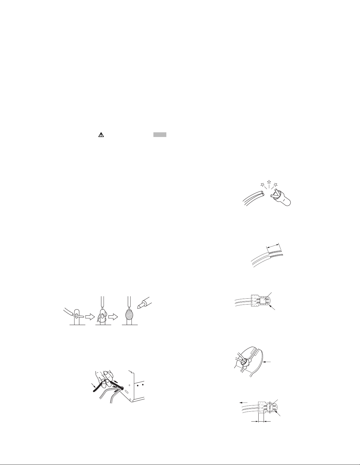
(12) Crimp type wire connectorIn such cases as when replacing
the power transformer in sets where the connections between the power cord and power trans former primary lead
wires are performed using crimp type connectors, if replacing the connectors is unavoidable, in order to prevent safety hazards, perform carefully and precisely according to the
following steps.
• Connector part number :E03830-001
• Required tool : Connector crimping tool of the proper
type which will not damage insulated parts.
• Replacement procedure
a) Remove the old connector by cutting the wires at a
point close to the connector.Important : Do not reuse a connector (discard it).
cut close to connector
Fig.1-1-3
b) Strip about 15 mm of the insulation from the ends
of the wires. If the wires are stranded, twist the
strands to avoid frayed conductors.
15 mm
Fig.1-1-4
c) Align the lengths of the wires to be connected. In-
sert the wires fully into the connector.
Metal sleeve
Fig.1-1-1
(7) Observe that wires do not contact heat producing parts
(heatsinks, oxide metal film resistors, fusible resistors, etc.)
(8) Check that replaced wires do not contact sharp edged or
pointed parts.
(9) When a power cord has been replaced, check that 10-15
kg of force in any direction will not loosen it.
Power cord
Fig.1-1-2
(10) Also check areas surrounding repaired locations.
(11) Products using cathode ray tubes (CRTs)In regard to such
products, the cathode ray tubes themselves, the high voltage circuits, and related circuits are specified for compliance with recognized codes pertaining to X-ray emission.
Connector
Fig.1-1-5
d) As shown in Fig.1-1-6, use the crimping tool to
crimp the metal sleeve at the center position. Be
sure to crimp fully to the complete closure of the
tool.
1 25
2 0
5 5
Crimping tool
Fig.1-1-6
e) Check the four points noted in Fig.1-1-7.
Not easily pulled free
Wire insulation recessed
more than 4 mm
Crimped at approx. cente
of metal sleeve
Conductors extended
Fig.1-1-7
(No.YD048)1-3
Page 4
1.1.2 Safety Check after Servicing
Examine the area surrounding the repaired location for damage
or deterioration. Observe that screws, parts and wires have been
returned to original positions, Afterwards, perform the following
tests and confirm the specified values in order to verify compliance with safety standards.
(1) Insulation resistance test
Confirm the specified insulation resistance or greater between power cord plug prongs and externally exposed
parts of the set (RF terminals, antenna terminals, video and
audio input and output terminals, microphone jacks, earphone jacks, etc.).See table 1 below.
(2) Dielectric strength test
Confirm specified dielectric strength or greater between
power cord plug prongs and exposed accessible parts of
the set (RF terminals, antenna terminals, video and audio
input and output terminals, microphone jacks, earphone
jacks, etc.). See Fig.1-1-11 below.
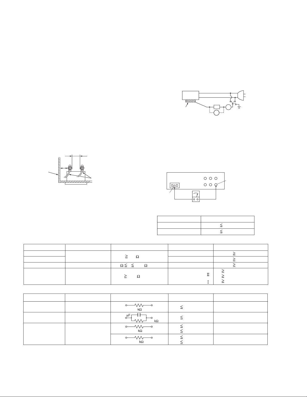
(3) Clearance distance
When replacing primary circuit components, confirm specified clearance distance (d), (d') between soldered terminals, and between terminals and surrounding metallic
parts. See Fig.1-1-11 below.
d
Chassis
d'
Power cord
primary wire
Fig.1-1-8
(4) Leakage current test
Confirm specified or lower leakage current between earth
ground/power cord plug prongs and externally exposed accessible parts (RF terminals, antenna terminals, video and
audio input and output terminals, microphone jacks, earphone jacks, etc.).
Measuring Method : (Power ON)Insert load Z between
earth ground/power cord plug prongs and externally exposed accessible parts. Use an AC voltmeter to measure
across both terminals of load Z. See Fig.1-1-9 and following Fig.1-1-12.
ab
Externally
exposed
accessible part
Z
V
c
A
Fig.1-1-9
(5) Grounding (Class 1 model only)
Confirm specified or lower grounding impedance between
earth pin in AC inlet and externally exposed accessible
parts (Video in, Video out, Audio in, Audio out or Fixing
screw etc.).Measuring Method:
Connect milli ohm meter between earth pin in AC inlet and
exposed accessible parts. See Fig.1-1-10 and grounding
specifications.
AC inlet
Earth pin
Exposed accessible part
MIlli ohm meter
Grounding Specifications
Region
USA & Canada
Europe & Australia
Grounding Impedance (Z
Z 0.1 ohm
Z 0.5 ohm
)
Fig.1-1-10
AC Line Voltage
100 V
100 to 240 V
110 to 130 V
110 to 130 V
200 to 240 V
Region
Japan
USA & Canada
Europe & Australia
Insulation Resistance (R
R 1 M /500 V DC
1 M R 12 M /500 V DC
R 10 M /500 V DC
)
Dielectric Strength
AC 1 kV 1 minute
AC 1.5 kV 1 minute
AC 1 kV 1 minute
AC 3 kV 1 minute
AC 1.5 kV 1 minute
(
Class
(
Class
Clearance Distance (d), (d'
d, d' 3 mm
d, d' 4 mm
d, d' 3.2 mm
d 4 m m
)
d' 8 m m (Power cord
d' 6 m m (Primary wire
)
Fig.1-1-11
AC Line Voltage
100 V
110 to 130 V
110 to 130 V
220 to 240 V
Region
Japan
USA & Canada
Europe & Australia
Load Z
1
0.15
1.5
2
50
Leakage Current (i)
i 1 mA rms
i 0.5 mA rms
i 0.7 mA peak
i 2 mA dc
i 0.7 mA peak
i 2 mA dc
a, b, c
Exposed accessible parts
Exposed accessible parts
Antenna earth terminals
Other terminals
Fig.1-1-12
NOTE :
These tables are unofficial and for reference only. Be sure to confirm the precise values for your particular country and locality.
)
)
)
1-4 (No.YD048)
Page 5
1.2 Hard Disk Drive (HDD) Handling Precautions
The HDD is a precision device for use in reading and writing a large amount of data on or from a disk rotating at a high speed. If it is
not handled carefully, either abnormal operation may result or it may not be possible to read data. The HDD is sensitive to the following
items and special care is required in safeguarding against them when handling an HDD. Also take care in handling a set incorporating
an HDD.
(1) Vibrations and impacts
(2) Static electricity
(3) Rough handling
1.2.1 Handling in transport, etc.
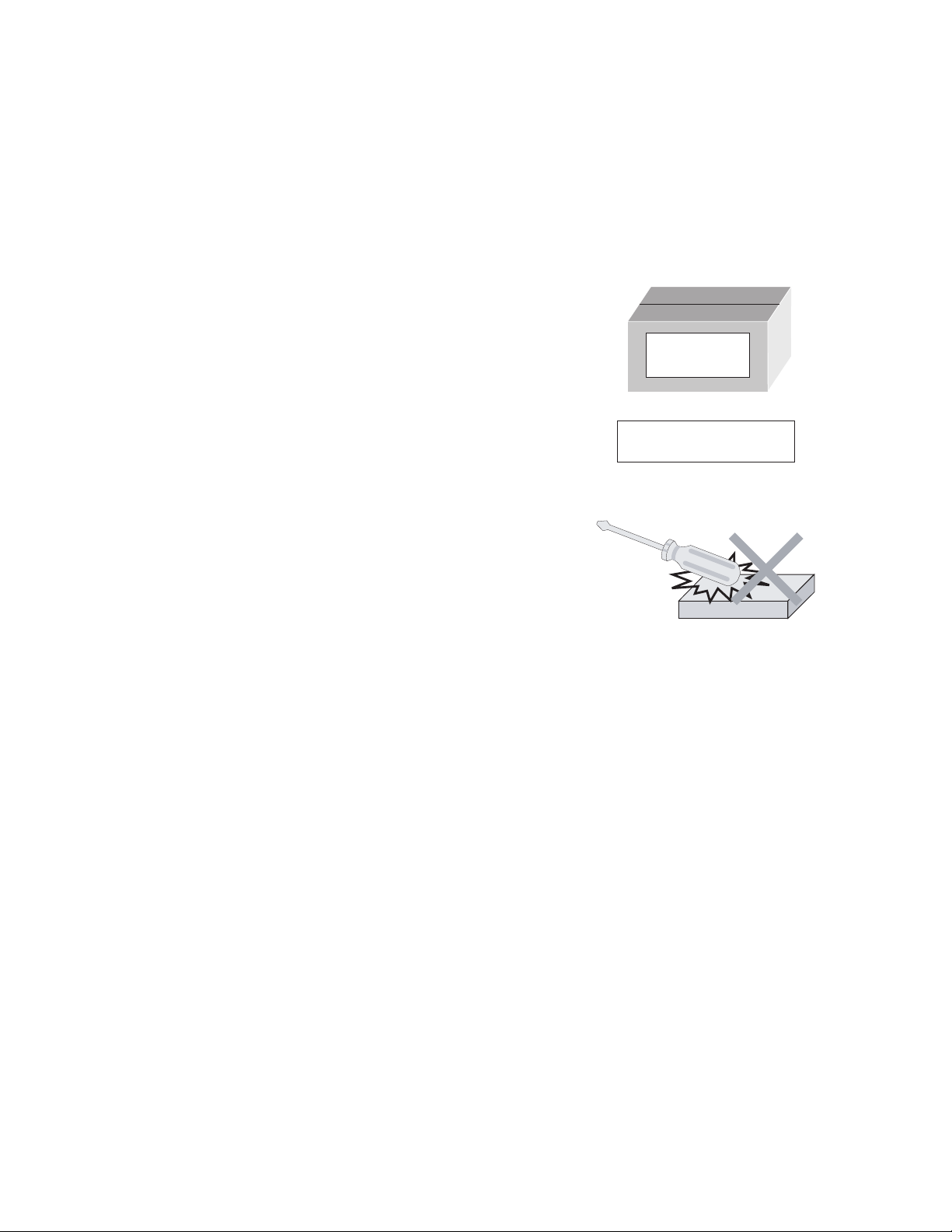
• Be sure to place the HDD in the manufacturer's specified package carton before transport.
• When receiving a package containing an HDD, check that the
package carton is not damaged (such as having holes in the
carton, crushed corners, etc.).
• Do not impact the packaging carton when loading or unloading
HDD
Do not throw or
drop packages.
it.
• It is not permitted to use the inner package carton only for
transporting an HDD.
• Do not stack package cartons one upon another.
Be sure to package and
transport the HDDs correctly.
1.2.2 Handling an HDD in the stand-alone status
• When handling an HDD on a hard workbench, place an antistatic mat (rubber sheet) or similar object on the hard surface
(to prevent any impacts occurring between the HDD and
bench).
• Do not stack the HDDs one upon another.
• Do not knock an HDD with a hard object (such as a screwdriver).
• Do not place an HDD on its side panel without using a support
(do not place an HDD in an unstable position).
1.2.3 Handling the installation of an HDD
• Place antistatic mats or similar sheets on all of the surfaces on which work is conducted or when the HDD is transported.
• Do not permit the HDD to knock against the set's brackets.
• When screwing the brackets, be careful not to knock the HDD. When using a power screwdriver, use a low-shock model and arrange
the tightening torque properly.
• When mounting an HDD in a main body, take care not to apply excessive force to the brackets.
(No.YD048)1-5
Page 6
SECTION 2
SPECIFIC SERVICE INSTRUCTIONS
2.1 Different table of features
The following table indicates main different points between models DR-MX1SEK, DR-MX1SEU/EY/EZ and DR-MX1SEF.
ITEM DR-MX1SEK DR-MX1SEU / EY / EZ DR-MX1SEF
POWER PLUG 3PIN CEE ←
VHS PAL/NTSC PB on PAL TV with
HiFi
BROADCASTING STANDARD I B/G, D/K L, L', B/G
STEREO DECODER NICAM NICAM/A2 NICAM(L, B/G) / A2(B/G)
VCR PLUS+ VIDEO Plus+DELUXE SHOWVIEW DELUXE ←
VPS/PDC NOT USED USED NOT USED
Note:
Mark ← as same as left.
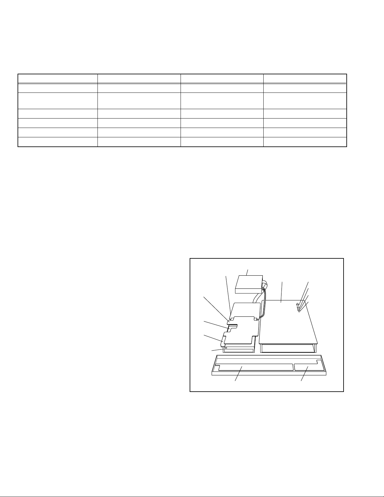
2.2 Service position
This unit has been designed so that the Mechanism and Main
board assemblies can be removed together from the bottom
chassis. Before diagnosing or servicing the circuit boards, take
out the major parts from the bottom chassis.
2.2.1 How to set the "Service position"
(1) Refer to the disassembly procedure and perform the disas-
sembly of the major parts before removing the Mechanism
assembly.
(2) Remove the screws that fix the Mechanism, Main board as-
sembly to the bottom chassis. If any other screws are used
to fix the boards, remove them also.
(3) Remove the combined Mechanism, HDD, DVD unit,
switching regulator, digital, junction and Main board as-
semblies.
(4) If any other major parts are used, remove them also.
(5) Connect the wires and connectors of the major parts that
have been removed in steps (1) to (4). (Refer to Fig. 2-2a.)
(6) Place the combined Mechanism, Main board and other
board assemblies upside down.
(7) Insert the power cord plug into the power outlet and then
proceed with the diagnostics and servicing of the board as-
sembly.
Notes:
• Before inserting the power cord plug into the power out-
let, make sure that none of the electrical parts are able
to short-circuit between the workbench and the board
assembly.
• For the disassembly procedure of the major parts and
details of the precautions to be taken, see "Removing
the major parts".
• If there are wire connections from the Main board and
Mechanism assemblies to the other major parts, be sure
to remove them (including wires connected to the major
parts) first before performing step (2).
• When carrying out diagnosis and repair of the Main
board assembly in the "Service position", be sure to
ground both the Main board and Mechanism assemblies. If they are improperly grounded, there may be
noise on the playback picture or FDP counter display
may move even when the mechanism is kept in an inoperative status.
PAL/MESECAM (MANUAL) /
NTSC PB on PAL TV with HiFi
←
• In order to diagnose the playback or recording of the
cassette tape, set the Mechanism assembly to the required mode before placing it upside down. If the mechanism mode is changed (including ejection) while it is in
an upside down position the tape inside may be damaged.
• For some models, the mechanism and board assem-
blies are attached by connectors only. When carrying
out a diagnosis or repair of the boards in the "Service
position", make sure that the connectors are not disconnected.
Switchcing regulator
board assy
Junction board
assy
Digital board
assy
Jack board
assy
DVD WPKV
Switch display board assy
HDD
Main board assy
Operation jack board assy
TP111 D.FF
TP106 PB FM
TP2253 A.PB FM
TP4001 CTL.P
Fig.2-2a
1-6 (No.YD048)
Page 7
2.3 Jig RCU mode
This unit uses the following two modes for receiving remote control codes.
(1) User RCU mode:Ordinary mode for use by the user.
(2) Jig RCU mode: Mode for use in production and servicing.
When using the Jig RCU, it is required to set the unit to the Jig
RCU mode (the mode in which codes from the Jig RCU can be
received). As both of the above two modes are stored in the EEPROM, it is required to set the unit back to the User RCU mode
each time that an adjustment is made or to check that the necessary operations have been completed.These modes can be set
by the operations described below.
Note:
• When the unit is set to Jig RCU mode and when the unit
is under Jig RCU mode, the remote control unit attached
to product operates only in "Remote Control Code 1".
Since the unit is in "Remote Control Code 3" when it is
shipped and just after its batteries are changed, "Remote Control Code 3" needs to be changed to "Remote
Control Code 1."
• Confirm the RCU mode when exchanged parts. Since
some SERVICE PARTS sets the unit to the Jig RCU
mode as initial setting. Therefore please set the unit to
the user RCU mode after replacing the EEPROM.
User RCU mode
Jig RCU mode
( blinked)
Fig.2-3a User/Jig RCU mode
2.3.1 Changing Remote Control Code
(1) Slide the TV/CABLE/SAT/DVD switch to DVD.
(2) Press the numeric button "1" of the remote control unit
while pressing the "SET UP" button of the remote control
unit. Then,press the "ENTER" button, and then release the
"SET UP" button.
(3) Press the "POWER" button on the unit to turn off the unit.
(4) Press the "PLAY" button on the unit for over 5 seconds
while the unit is turned off. The code currently set appears
on the front display panel.
(5) Press the "STOP" button on the remote control to change
the unit’s code. When FDP indicator displays "DVD1," it
means that the Remote Control Code has been changed to
"1."
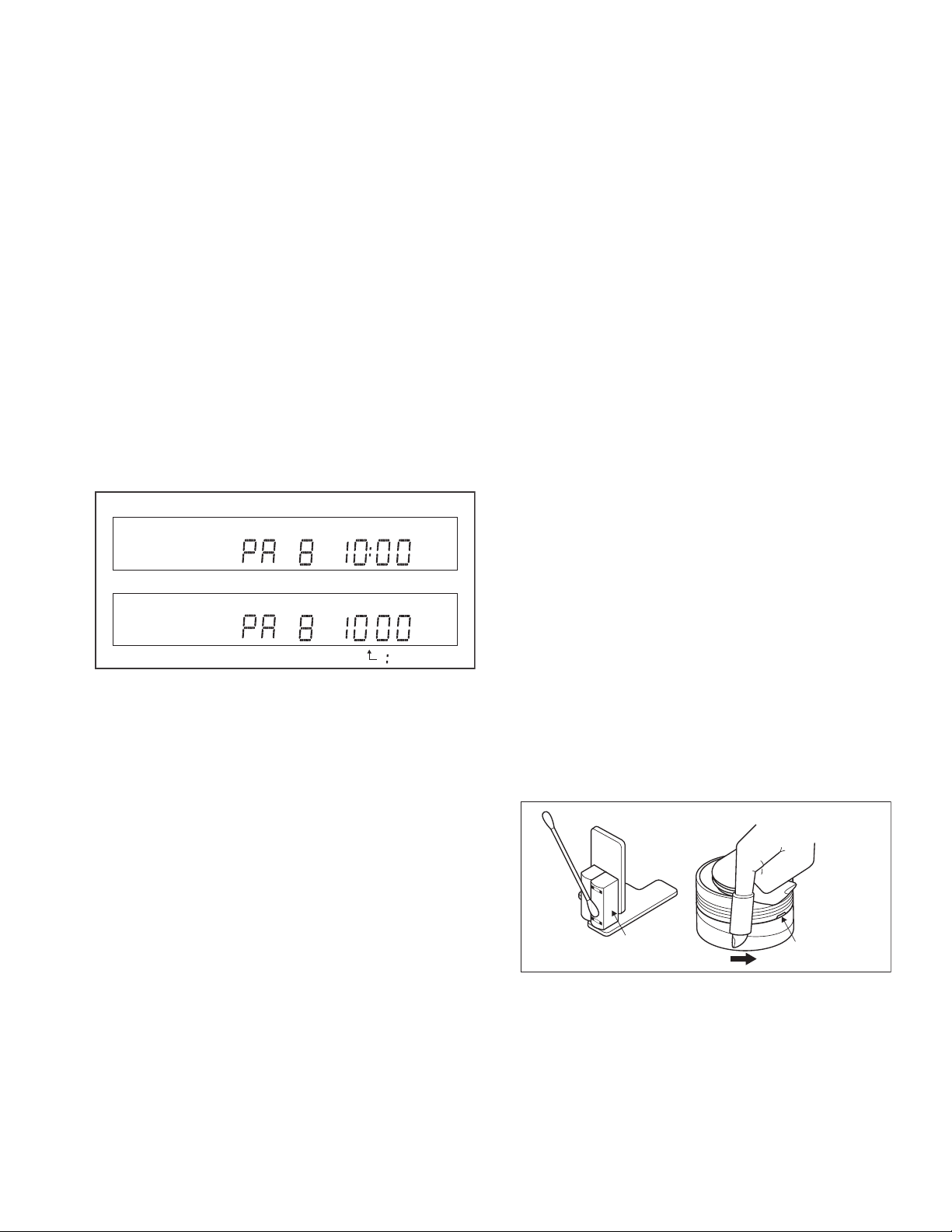
2.3.2 Setting the Jig RCU mode
(1) Turn on the power.
(2) Press the "VHS/HDD/DVD SELECT" button repeatedly on
the unit so that the VHS lamp lights up on the unit.
(3) Press the following remocon keys continuously within 2
seconds " SET UP " → " 2 " → " 8 " → " ENTER ".
When the unit is set to the Jig RCU mode, the symbols
( " : " ) in the time display of the FDP are blinked.
(Refer to Fig.2-3a User/Jig RCU mode)
2.3.3 Setting the User RCU mode
(1) Turn off the power.
(2) Press the "REC" and "PAUSE" buttons of the VCR simul-
taneously. Alternatively, transmit the code "43-9D" from the
Jig RCU.
2.4 Mechanism service mode
This model has a unique function to enter the mechanism into every operation mode without loading of any cassette tape. This
function is called the "Mechanism service mode".
2.4.1 How to set the "Mechanism service mode"
(1) Set the unit to the Jig RCU mode (the mode in which codes
from the Jig RCU can be received)
(2) Transmit the code "43-E5" from the Jig RCU.
(3) Release the lug of the Cassette holder and then slide the
Cassette holder toward the direction where the Cassette
holder is loaded by manually.
(4) The cassette holder lowers and, when the loading has
completed, the mechanism enters the desired mode.
When the unit is set to the Mechanism service mode, the
symbols ("TIMER") in the FDP (LED) are blinked.
2.4.2 How to exit from the "Mechanism service mode"
(1) Unplug the power cord plug from the power outlet.
2.5 Maintenance and inspection
2.5.1 Cleaning
Regular cleaning of the transport system parts is desirable but
practically impossible. So make it a rule to carry out cleaning of
the tape transport system whenever the machine is serviced.
When the video head, tape guide and/or brush get soiled, the
playback picture may appear inferior or at worst disappear, resulting in possible tape damage.
Note:
• Absolutely avoid sweeping the upper drum vertically as
this will cause damage to the video head.
(1) When cleaning the upper drum (especially the video head),
soak a piece of closely woven cloth with alcohol and while
holding the cloth onto the upper drum by the fingers, turn
the upper drum counterclockwise.
(2) To clean the parts of the tape transport system other than
the upper drum, use a piece of closely woven cloth or a cot-
ton swab soaked with alcohol.
(3) After cleaning, make sure that the cleaned parts are com-
pletely dry before using the cassette tape.
A/C head
Video heads
Fig.2-5a
2.5.2 Lubrication
With no need for periodical lubrication, you have only to lubricate
new parts after replacement. If any oil or grease on contact parts
is soiled, wipe it off and newly lubricate the parts.
Note:
• See the "mechanism assembly" diagram of the "parts
list" for the lubricating or greasing spots, and for the
types of oil or grease to be used.
(No.YD048)1-7
Page 8

2.5.3 Suggested servicing schedule for main components
The following table indicates the suggested period for such service measures as cleaning, lubrication and replacement. In practice, the indicated periods will vary widely according to
environmental and usage conditions. However, the indicated
components should be inspected when a set is brought for service and the maintenance work performed if necessary. Also
note that rubber parts may deform in time, even if the set is not
used.
System Parts name
Drum assembly C,X X
A/C head C,X C,X
Tape
transport
Drive
Other Rotary encoder X
C : Cleaning
X : Inspection or Replacement if necessary
Pinch roller arm assembly C C
Full erase head C C
Tension arm assembly C C
Capstan motor (Shaft) C C
Guide arm assembly C C
Capstan motor X
Capstan brake assembly X
Main brake assembly X
Belt (Capstan) X X
Loading motor X
Clutch unit X
Worm gear X
Control plate X
Operation hours
1000H 2000H
1-8 (No.YD048)
Page 9

SECTION 3
DISASSEMBLY
3.1 Removing the major parts
3.1.1 Destination of connectors
Two kinds of double-arrows in connection tables respectively
show kinds of connector/wires.
: The connector of the side to remove
CONN. No. PIN No.CONNECTOR
WR2a
WR2b
Main CN101
Main CN103
Destination of connectors
CONN. No. PIN No.CONNECTOR
WR2a
WR2b
WR2c
WR3a
WR3b
WR4a
WR4b
WR5a
WR5b
WR5c
CN7108
(CN1001)
CN7109
(CN1002)
CN7121
(CN1801)
WR6a
WR7a
WR7b
WR7c
WR7d
WR7e
WR8a
WR8b
WR8c
WR12a
WR12b
WR12c
WR13a
WR13b
Main
Main
Junction
Main
Drum
assembly
DVD unit
DVD unit
HDD
Junction
Junction
Junction
Junction
Junction
Junction
Junction
Main
Main
Junction
SW. REG.
SW. REG.
SW. REG.
SW. REG.
Tuner
Tuner
Tuner
Main
Video switch
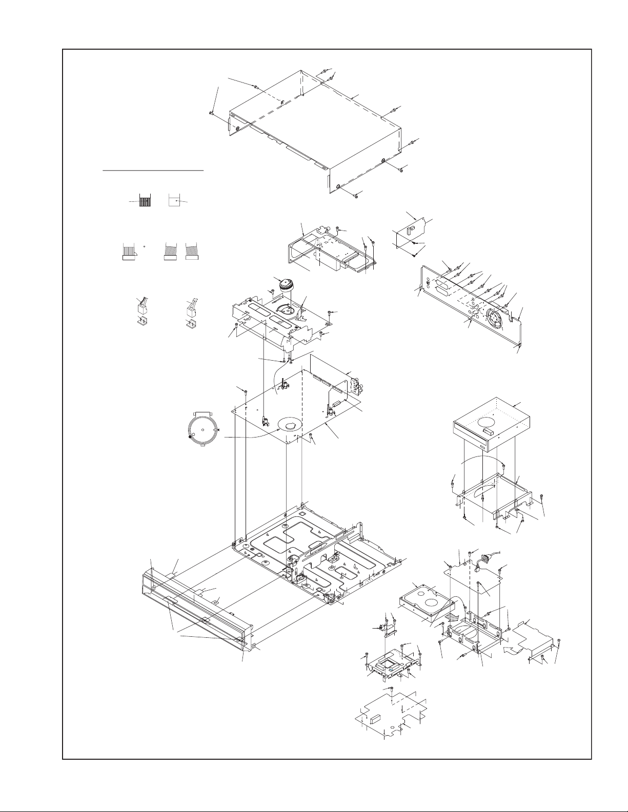
3.1.2 How to read the procedure table
This table shows the steps for disassembly of the externally furnished parts and board assemblies. Reverse these steps when
re-assembling them.
Step/
Loc No.
[1] Top cover 3 1a
Part Name
Bracket 2(S1c)
: Wire: Flat wire : Board to board (B-B)
Digital CN761
Digital CN762
CN7112
CN3102
CN7103
CN2001
CN7106
CN5502
CN7108
CN7109
CN7121
CN7126
CN7123
CN3103
CN2601
CN7107
CN5304
CN5301
CN5302
CN5303
CN6001
CN6003
CN6002
CN7119
CN504
Operation/jack
Switch/display
Switch/display
A/C head
Main
Digital
Junction
Digital
Digital
Digital
Digital
Digital
Digital
Jack
Video switch
Junction
Junction
Main
Junction
Main
Fun motor
HDD
Main
Main
Main
SECAM
SECAM
Fig.
No.
4(S1a),(S1b),3(L1a), <Note 1a>
2(SD1a),(P1a),(W1a),
CN1(WR1a),
CN7201
CN7001
CN7002
CN2201
CN5304
CN2101
CN1405
CN1003
CN1001
CN1002
CN1801
CN4104
CN501
CN7102
CN8001
CN7111
CN5501
CN5311
CN7116
CN7118
CN7117
CN301
CN4302
Point Note
CN1
40
10
9
11
4
6
9
40
4
40
4
6
28
20
10
6
4
15
11
9
19
15
2
4
14
7
13
15
6
(1) Order of steps in Procedure
When reassembling, perform the step(s) in the reverse or-
der.
These numbers are also used as the identification (loca-
tion) No. of parts Figures.
(2) Part name to be removed or installed.
(3) Fig. No. showing procedure or part location.
(4) Identification of part to be removed, unhooked, unlocked,
released, unplugged, unclamped or unsoldered.
P= Spring, W= Washer, S= Screw, L= Locking tab, SD=
Solder, CN**(WR**)= Remove the wire (WR**) from the
connector (CN**).
Note:
• The bracketed ( ) WR of the connector symbol are
assigned nos. in priority order and do not correspond to those on the spare parts list.
(5) Adjustment information for installation
3.1.3 Disassembly procedure
Step/
Loc No.
[1]
[2]
[3]
[4]
[5]
[6]
[7]
[8]
[9]
[10]
[11]
[12]
[13]
Part Name
Top cover
Front panel assembly
(Operation/jack board assembly)
(Switch/display board assembly)
Mechanism assembly
(Drum assembly)
DVD unit
(Bracket)
Digital board assembly
Jack board assembly
Junction board assembly
Switching Regulator
board assembly
Rear cover
HDD
(Bracket, sheet)
Main board assembly
Tuner board assembly
SECAM board assembly
(EF model)
Fig.
No.
3 1d
3 1a,
3 1d
3 1e
3 1b,
3 1c,
3 1d
3 1e
3 1d
3 1e
3 1d
3 1e
3 1d
3 1d
3 1e
3 1d
3 1e
3 1d
3 1d
3 1e
3 1d
3 1d
3 1e
3 1d
3 1e
Point Note
8(S1a)
3(L2a),5(L2b)
CN7112(WR2a)
CN3102(WR2b)
CN7103(WR2c)
CN2001(WR3a)
3(S3a),(S3b)
CN(WR3b)
(S3c),(S3d),(S3e)
4(S4a),4(S4b)
(WR4a),(WR4b)
4(S5a),CN2101(WR5a)
CN7106(WR5b),CN5502(WR5c)
CN7108(CN1001),CN7109(CN1002),
CN7121(CN1801)
2(S6a),CN7126(WR6a)
(S7a),CN7123(WR7a),
CN3103(WR7b),CN2601
(WR7c),CN7107(WR7d),
CN5304(WR7e)
4(S8a)
CN5301(WR8a),
CN5302(WR8b),
CN5303(WR8c)
(S9a),8(S9b),(S9c),3(L9a)
4(S10a),4(S10b)
2(S11a)
CN6001(WR12a),CN6003
(WR12b),CN6002(WR12c)
2(S13a), CN7119(WR13a)
CN504(WR13b)
<Note2a>
<Note2b>
<Note2a>
<Note3a>
<Note3b>
<Note2a>
<Note2a>
<Note2a>
<Note2a>
<Note 2a>
• Be careful not to damage the connector and wire etc. during
connection and disconnection.
• When connecting the flat wire to the connector, be careful with
the flat wire direction.
(1) (2) (3) (4) (5)
(No.YD048)1-9
Page 10
<Note 2b>
• When reattaching the Front panel assembly, make sure that
the door opener of the Side frame (R) is lowered in position prior to the reinstallation.
• When reattaching the Front panel assembly, pay careful attention
to the switch lever of the Front panel assembly not to make it
touch the switch knob of the Main board assembly from the side.
• When reattaching the Front panel assembly, lift the Cassette
door slightly.
• When reattaching the Mechanism assembly to the Main board
assembly, take care not to damage the sensors and switch on
the Main board assembly.
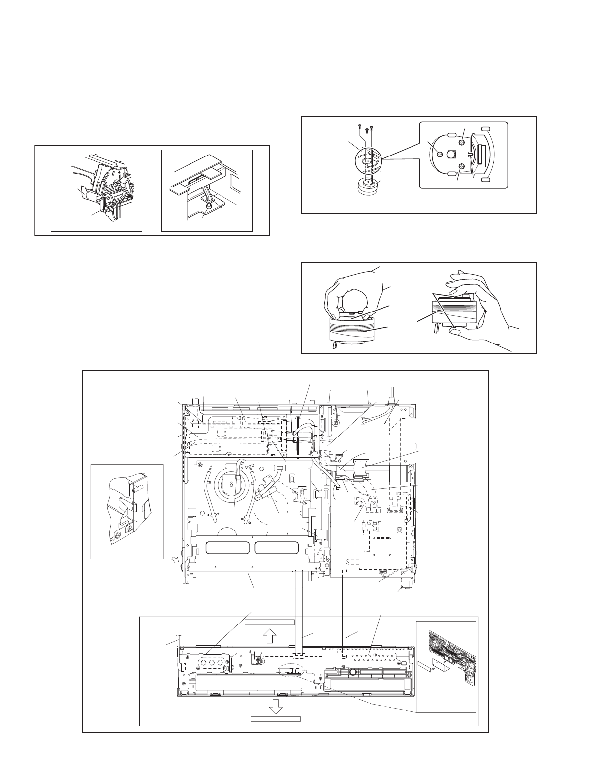
<Note 3c>
• When reattaching the Drum assembly, secure the screws (S3c
to S3e) in the order of c, d, e.
Mechanism
assembly
(S3d)
(S3c)
(S3e)
(S3d)
(S3e)
Door
opener
Side
frame(R)
Switch
knob
Switch
lever
Fig.3-1a
<Note 3a>
• When reattaching the Mechanism assembly, secure the
screws (S3a to S3b) in the order of 1,2,3.
<Note 3b>
• When reattaching the Mechanism assembly, be sure to align
the phase of the Rotary encoder on the Main board assembly.
• When reattaching the Mechanism assembly, set the “Mechanism assembling mode”. [See “MECHANISM ASSEMBLY
SERVICE MANUAL (No. 86700)”.]
Video switch board assmbly
)
(
WR
13a
>
<Note
2a
A/C HEAD
)
(
WR
>
<Note
assembly
BOTTOM SIDE
Demod board
assembly
Tuner board
assembly
SECAM board
assembly
(
WR
13b
<Note
CN720
CN3104
DRAWING FROM DIRECTION
C
from FRONT PANEL
(OPE/JACK CN7201)
to MAIN BOARD ASSY
(CN7112)
(
)
WR
2a
<Note
2a
Terminal board
CN4302
CN301
)
2a
>
C
>
(
WR
assembly
CN7112
<Note
(
WR
<Note
3b
12a
2a
2a
CN7116
Main boad
Operation/jack board assembly
CN7201
FW7001
CN72
Drum
assembly
<Note 3c>
<NOTE>
Attach the Drum assembly appropriately,
since the insta lation state of the Drum assembly
influences the FM WAVEFORM LINEARITY
greatly
(S3c)
HOOK
Fig.3-1b
• When handling the drum assembly alone, hold it by the motor
or shaft. Be careful not to touch other parts, especially the video heads. Also take care not to damage the connectors.
Shaft
Motor
Video heads
Fig.3-1c
)
(
WR
)
>
CN7117
(
<Note
CN2001
3a
2a
WR
CN6001
CN6 03
CN6002
(
WR
<Note
)
>
(
WR
12b
CN501
7b
2a
CN3102
12c
CN504
2a
)
>
(
WR
)
CN7118
)
>
7c
<Note
CN7001
CN 31
(
CN7111
)
CN2601
CN3103
WR
<Note 2a>
FAN
(
)
WR
8b
CN5001
CN5302
Sitching regulator
CN5301
board assembly
(
)
WR
8c
(
WR
7d
<Note
CN5303
CN5304
CN5501
CN7107
CN7123
(
WR4b
CN8001
(
WR
<Note
CN7102
(
WR
DRIVE UNIT
Junct on
board assembly
CN550
)
)
CN5502
7a
2a
>
)
5c
CN2201
Digital board assembly
CN7103
CN7126
(
WR
6a
Switch/display board assembly
)
(
WR
CN7002
<Note
2c
2a
>
)
2b
2a
>
8a
)
2a
)
)
(
WR
5a
<Note
2a
>
(
WR
CN7106
CN2101
N410
<Note
(
WR
<Note
(
WR
<Note
>
Jack board assmbly
Soldering side
)
7e
2a
>
)
4a
2a
>
)
5b
2a
>
1-10 (No.YD048)
NOTE) INSERT FFC WIRE
TO THE CONNECTOR BEFORE
ATTACHING TO FRONT PANEL.
TOP SIDE
Fig.3-1d
Page 11
(S1a)
(S1a)
[1]Top cover
(S1a)
(S1a)
NOTE
1. Insert direction of FFC WIRE as follows.
right side
electrode side
2. FFC WIRE and DRUM FPC WIRE
should be insert as follows.
OK
CN
back side
supporting side
NG
90
CN
CN
3. Insert direction of POWER CORD.
US/UC/JPN
WHITE LINE
NEUTRAL
CN5001
except US/UC/JPN
BLUE
NEUTRAL
CN5001
JS3001
<Phase alignment>
.
Accord the position of V gap
R.ENCORDER and PWB silk
.
Accord the position of Boss
on R.ENCORDER and PWB silk
(L2b)
(L2a)
j
(L2b)
[12]Tuner board assembly
[3]Drum assembly
(S3a)
<Note
3a
>
j
(S3a)
<Note
3a
>
(S3c)
<Note
3b
>
(S11a)
j
(L2a)
j
(L2b)
[2]Front panel assembly
<Note 2b>
u
v
p
w
[3]VHS Mechanism assembly
j
(S3e)
<Note
g
3b
h
JS3001
g
(S3d)
<Note 3b>
p
CN914
CN7113
CN913
CN7114
>
a
(S11a)
i
h
a
b
e
a
d
[5]Digital board assembly
(S12a)
(S3a)
<Note
3a
(S3b)
<Note
3a
>
Terminal
board assembly
Video switch
board assembly
[11]Main board
assembly
n
n
c
c
e
e
e
b
e
d
k
m
[6]Jack board
assembly
(S5a)
e'
d
(S1a)
(S1a)
[13]SECAM board assembly
v
w
(S13a)
(S9a)
n
n
i
(L9a)
>
[8]Switching regulator
board assembly
c
i
(S8a)
c
b
[10]HDD
r
(S6a)
r
(S10a)
k
(S5a)
e'
e'
(S7a)
e
d
e'
(S5a)
e'
e
e'
e
e'
e'
e
[7]Junction board assembly
e
u
r
c
(S10b)
(S4a)
(S9b)
i
(L9a)
b
t
CN5302
CN5001
r
c
r
[10]Bracket
(S9b)
(S4b)
(S8a)
(S8a)
r
c
s
b
f
r
c'
(S9b)
(S9c)
[9]Rear cover
f
i
(L9a)
[4]DVD unit
[4]Bracket
b
(S4b)
(S8a)
(S10b)
c'
c
b
(S4a)
[10]Sheet
c'
c'
(S10a)
Fig.3-1e
(No.YD048)1-11
Page 12
SECTION 4
ADJUSTMENT
4.1 Before adjustment
4.1.1 Precaution
• The adjustments of this unit include the mechanism com-
patibility and electrical adjustments. During the performance of this work, be sure to observe the precautions for
each type of adjustment.
• If there is a reference to a signal input method in the signal
column of the adjustment chart, “Ext. S-input” means the
Y/C separated video signal and “Ext. input” means the
composite video signal input.
• Unless otherwise specified, all measuring points and
adjustment parts are located on the Main board.
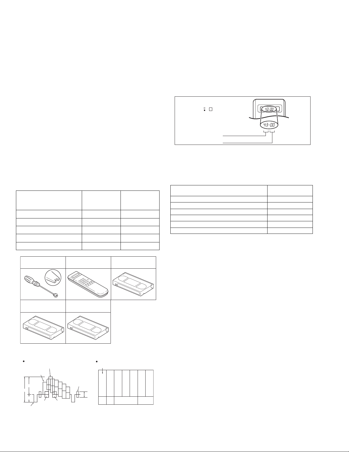
4.1.2 Required test equipments
• Color (colour) television or monitor
• Oscilloscope: wide-band, dual-trace, triggered delayed sweep
• Signal generator: RF / IF sweep / marker
• Signal generator: stairstep, color (colour) bar [PAL]
• Recording tape
• Digit-key remote controller(provided)
4.1.3 Required adjustment tools
--- : Not used
z
: Used
Roller driver
Mechanism
compatibility
adjustment
z ---
Electrical
adjustment
Jig RCU --- z
Back tension cassette gauge z ---
Alignment tape(MHPE) z ---
Alignment tape(MHPE-L) zz
Roller driver
PTU94002
Alignment tape
(SP, stairstep, PAL)
MHPE
Jig RCU
PTU94023B
Alignment tape
(LP, stairstep, PAL)
MHPE L
Back tension cassette gauge
PUJ48076 2
4.1.4 Color (colour) bar signal,Color (colour) bar pattern
Colour bar signal [PAL]
White(100%)
White(75%)
0 7 V
1V
0 3 V
Horizontal sync
Yellow
Cyan
Green
Magenta
Red
VU
V(R Y)
U(B Y)
Blue
Burst
Colour bar pattern [PAL]
(75%)
Cyan
White
Yellow
0 3 V
V
White
U Black
100%
Green
Magenta
Red
Blue
4.1.5 Switch settings
When adjusting this unit, set the VCR mode and switches
as described below.
• When using the Jig RCU, it is required to set the unit to the Jig
RCU mode (the mode in which codes from the Jig RCU can be
received). (See "section 2 SPECIFIC SERVICE INSTRUCTIONS".)
Jig RCU
[Data transmitting method]
Depress the " "( 3 ) button
after the data code is set.
CUSTOM CODE
43: A CODE
DATA CODE
INITIAL MODE
Fig.4-1a Jig RCU [PTU94023B]
• Set the switches as shown below unless otherwise specified
on the relevant adjustment chart. The switches that are not listed below can be set as desired.
If the VCR is not equipped with the functions detailed below,
setup is not required.
AUTO PICTURE/VIDEO CALIBRATION/
B.E.S.T./D.S.P.C.
PICTURE CONTROL/SMART PICTURE NORMAL/NATURAL
VIDEO STABILIZER OFF
TBC ON
Digital 3R ON
VIDEO NAVIGATION/TAPE MANAGER OFF
BLUE BACK OFF
OFF
4.1.6 Manual tracking mode (Auto tracking ON/OFF) set-
ting
(1) In order to set to the manual tracking mode during tape
playback, press the “CHANNEL +/-”button on the unit simultaneously.
• When the manual tracking mode is set, the tracking is
placed at the center position.
(2) Press “CHANNEL +/-” to adjust the tracking manually.
4.1.7 EVR Adjustment
Some of the electrical adjustments require the adjustment performed by the EVR system. The main unit have EEPROMs for
storing the EVR adjustment data and user setups.
Notes:
• In the EVR adjustment mode, the value is varied with the
channel buttons (+, -). The adjusted data is stored when
the setting mode changes (from PB to STOP, when the
tape speed is changed, etc.). Take care to identify the
current mode of each adjustment item when making an
adjustment.
• When changing the address setting in the EVR adjust-
ment mode, use the Jig RCU or the remote controller
having numeric keypad with which a numeric code can
be directly input.
The remote control code of the Jig RCU corresponds to
each of the digit keys on the remote controller as follows.
1-12 (No.YD048)
Page 13
Digit-key0123456789
Code 20 21 22 23 24 25 26 27 28 29
• As the counter indication and remaining tape indication
are not displayed FDP during the EVR adjustment
mode, check them on the TV monitor screen.
• When performing the EVR adjustment, confirm that the
FDP indication is changed to the EVR mode.
FDP
TENSION ARM
Stamping(b)
OK
CONTROL PLATE
Stamping(a)
Fig.4-1b EVR mode
4.2 Mechanism compatibility adjustment (VHS SECTION)
Notes:
• Although compatibility adjustment is very important, it
is not necessary to perform this as part of the normal
servicing work. It will be required when you have replaced the A/C head, drum assembly or any part of the
tape transport system.
• To prevent damaging the alignment tape in the compat-
ibility adjustment, prepare a cassette tape (for self-recording/playback), perform a test on it by transporting it
and making sure that the tape is not bent by the tape
transport mechanisms such as in the guide rollers.(See
Fig.4-2b.)
4.2.1 Tension pole position
Notes:
• This adjustment must be performed every time the ten-
sion band is replaced.
Signal (A) • Back tension cassette gauge [PUJ48076-2]
Mode (B1)
Adjustment part (F) • Adjust pin [Mechansim assembly]
Specified value (G)
•PB
(B2)
• Eject end
• 25 - 51 gf•cm (2.45 - 5 x 10
-3
Nm)
(1) Play back the back tension cassette gauge (A).
(2) Check that the indicated value on the left side gauge is
within the specified value (G).
(3) If the indicated value is not within the specified value (G),
perform the adjustment in a following procedure.(See
Fig.4-2a.)
a) Remove the top frame, cassette holder and side
frames (L/R) all together. (Refer to the SERVICE
MANUAL No.86700 [MECHANISM ASSEMBLY].)
b) Rotate the loading motor gear to move the control
plate so that the triangular stamping to the left of the
“P”stamping is aligned with the stamping (a) on the
main deck. This positioning is mode (B1).
c) Adjust by turning the adjustment pin so that the tip of
the tension arm is aligned with the stamping (b) on
the main deck.
d) Rotate the reel disk (S) by about one turn clockwise
and make sure that the round hole of the adjustment
pin is located in the “OK” range. If it is outside this
range, restart the adjustment from the beginning.
After completion of the adjustment, rotate the loading gear
motor to return it to the mode (B2) position.
ADJUST PIN
NG
Fig.4-2a
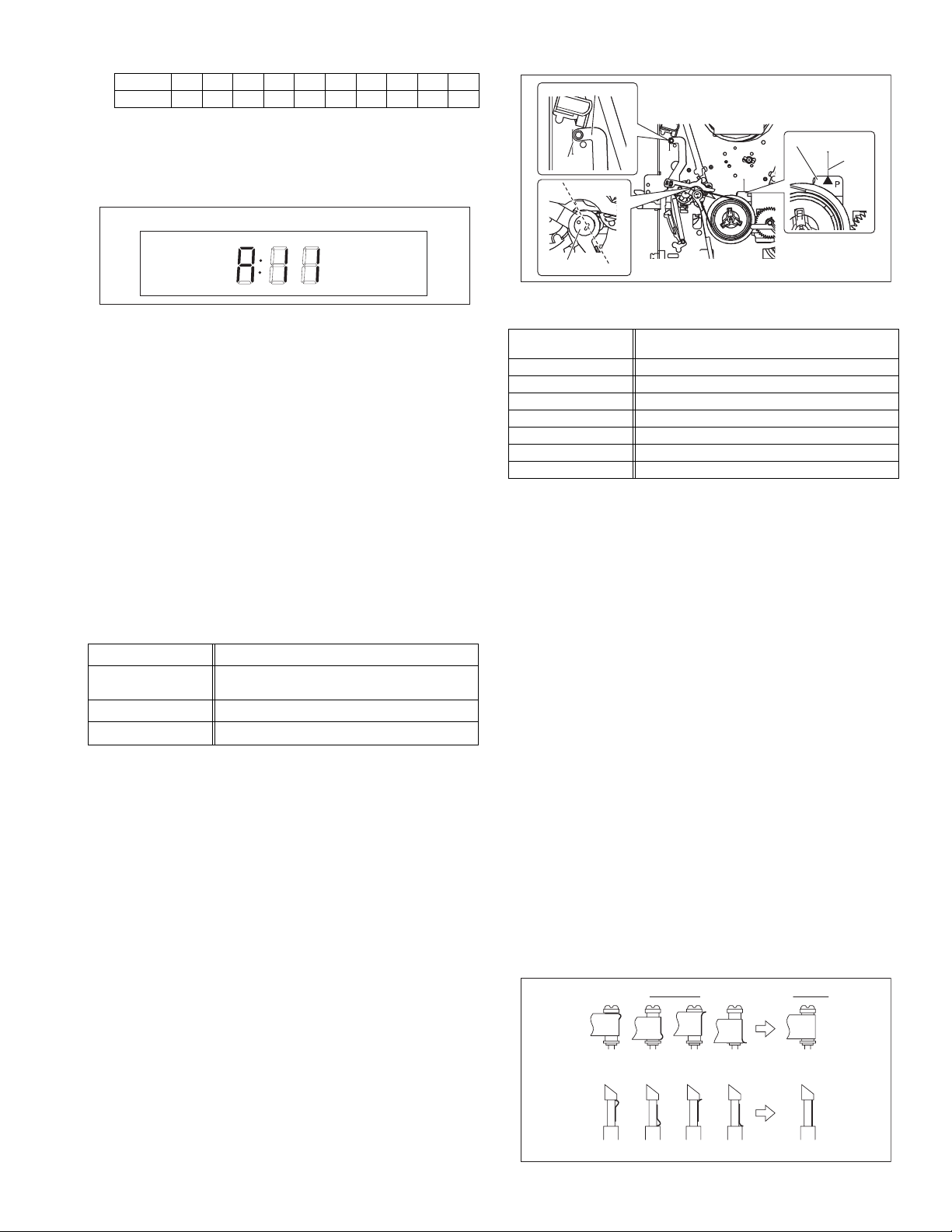
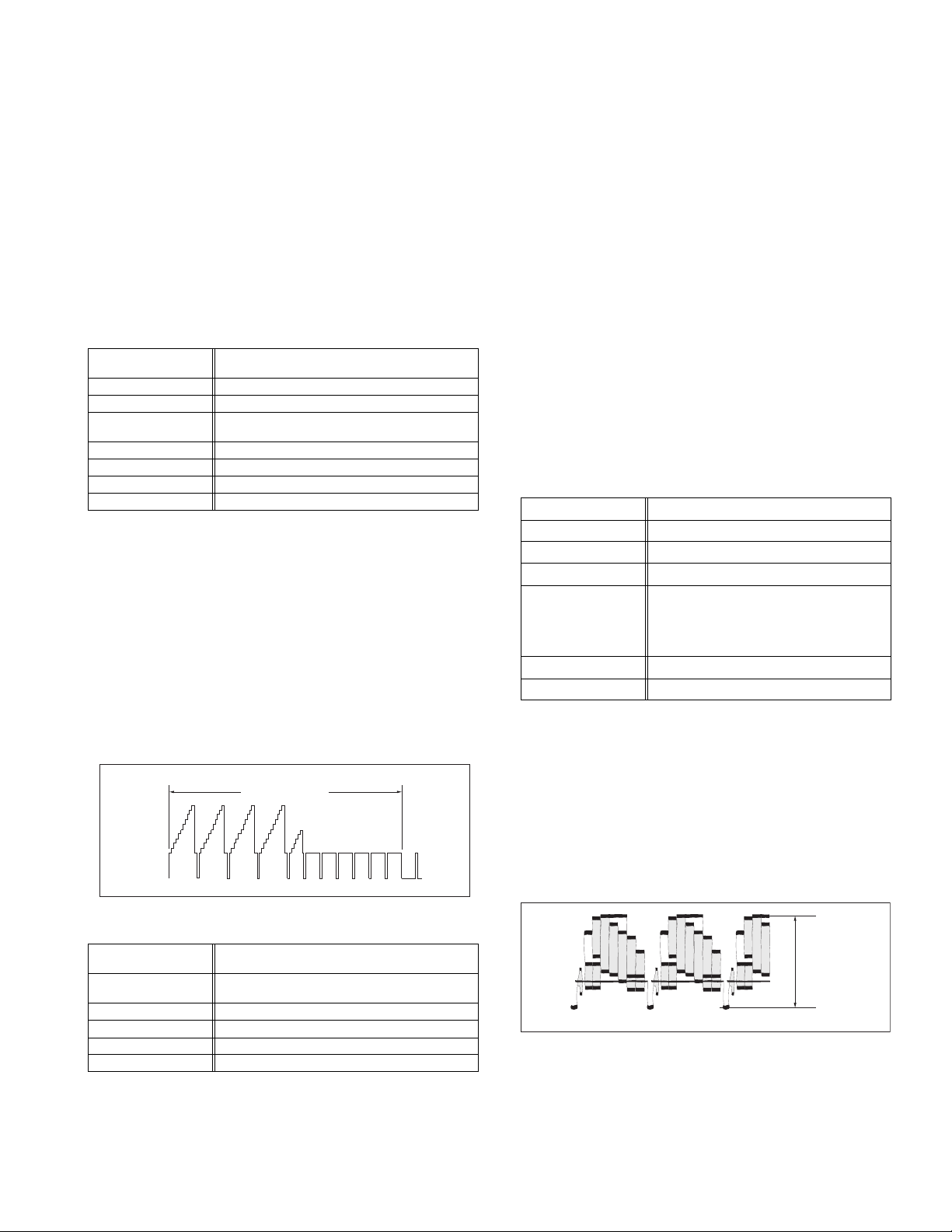
4.2.2 FM waveform linearity
Signal (A1)
Mode (B) • PB
Equipment (C) • Oscilloscope
Measuring point (D) • TP106 (PB. FM)
External trigger (E) • TP111 (D.FF)
Adjustment part (F) • Guide roller [Mechanism assembly]
Specified value (G) • Flat V.PB FM waveform
Adjustment tool (H) • Roller driver [PTU94002]
• Alignment tape(SP, stairstep, PAL) [MHPE]
(A2)
• Alignment tape(LP, stairstep, PAL) [MHPE-L]
(1) Play back the alignment tape (A1).
(2) Apply the external trigger signal to D.FF (E), to observe
the V.PB FM waveform at the measuring point (D).
(3) Set the VCR to the manual tracking mode.
(4) Make sure that there is no significant level drop of the V.PB
FM waveform caused by the tracking operation, with its
generally parallel and linear variation ensured. Perform the
following adjustments when required. (See Fig. 4-2c.)
(5) Reduce the V.PB FM waveform by the tracking operation.
If a drop in level is found on the left side, turn the guide roll-
er of the pole base assembly (supply side) with the roller
driver to make the V.PB FM waveform linear.
If a drop in level is on the right side, likewise turn the guide
roller of the pole base assembly (take-up side) with the
roller driver to make it linear. (See Fig. 4-2c.)
(6) Make sure that the V.PB FM waveform varies in parallel
and linearly with the tracking operation again. When re-
quired, perform fine-adjustment of the guide roller of the
pole base assembly (supply or take-up side).
(7) Unload the cassette tape once, play back the alignment
tape (A1) again and confirm the V.PB FM waveform.
(8) After adjustment, confirm that the tape wrinkling does not
occur at the roller upper or lower limits. (See Fig. 4-2b.)
[Perform adjustment step (9) only for the models equipped
with SP mode and EP (or LP) mode.]
[Perform adjustment step (9) only for the models
equipped with SP mode and EP (or LP) mode.]
(9) Repeat steps (1) to (8) by using the alignment tape (A2).
Improper
(a)
GUIDE ROLLER
Proper
(b)
GUIDE POLE
Fig.4-2b
(No.YD048)1-13
Page 14
Proper waveform variation
Improper waveform variation
A
C
Up Down
B
D
Roller driver
Guide roller
(supply side)
Fig.4-2c
4.2.3 Height and tilt of the A/C head
Note:
• Set a temporary level of the height of the A/C head in ad-
vance to make the adjustment easier after the A/C head
has been replaced. (Refer to the SERVICE MANUAL
No.86700 [MECHANISM ASSEMBLY].)
Signal (A) • Alignment tape(SP, stairstep, PAL) [MHPE]
Mode (B) • PB
Equipment (C) • Oscilloscope
Measuring point (D1)
External trigger (E) • TP111 (D.FF)
Adjustment part (F) • A/C head [Mechanism assembly]
Specified value (G) • Maximum waveform
• TP106 (PB. FM)
(D2)
• TP4001 (CTL. P)
(1) Play back the alignment tape (A).
(2) Apply the external trigger signal to D.FF (E), to observe the
AUDIO OUT waveform and Control pulse waveform at the
measuring points (D1) and (D2) in the ALT mode.
(3) Set the unit to the manual tracking mode.
(4) Adjust the AUDIO OUT waveform and Control pulse wave-
form by turning the screws (1), (2) and (3) little by little until
both waveforms reach maximum. The screw (1)
and (3) are for adjustment of tilt and the screw (2) for azi-
muth.
Head base
(2)
(1)
AUDIO OUT
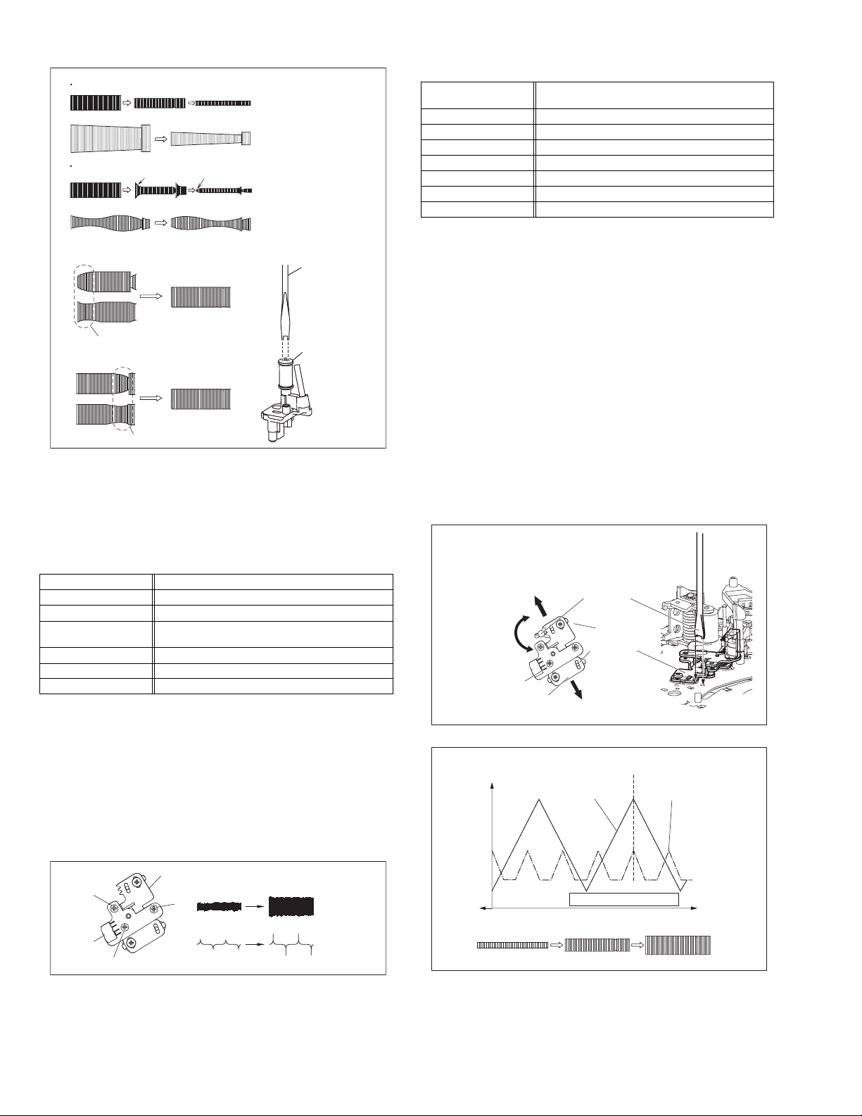
4.2.4 A/C head phase (X-value)
Signal (A1)
Mode (B) • PB
Equipment (C) • Oscilloscope
Measuring point (D) • TP106 (PB. FM)
External trigger (E) • TP111 (D.FF)
Adjustment part (F) • A/C head base [Mechanism assembly]
Specified value (G) • Flat V.PB FM waveform
Adjustment tool (H) • Roller driver [PTU94002]
• Alignment tape(SP, stairstep, PAL) [MHPE]
(A2)
• Alignment tape(LP, stairstep, PAL) [MHPE-L]
(1) Play back the alignment tape (A1).
(2) Apply the external trigger signal to D.FF (E), to observe the
V.PB FM waveform at the measuring point (D).
(3) Set the VCR to the manual tracking mode.
(4) Loosen the screws (4) and (5), then set the Roller driver to
the innermost projected part of the A/C head. (See Fig. 4-
2e.)
(5) Rotate the roller driver so that the A/C head comes closest
to the capstan. From there, move the A/C head back grad-
ually toward the drum until the point where the FM wave-
form is maximized for the second time, and then
tighten the screws (4) and (5) temporarily.
(6) Play an alignment tape (A2) and set to the manual-tracking
mode.
(7) Fine-adjust A/C head base position to maximize the FM
waveform, and then tighten the screws (4) and (5) firmly.
(8) Play alignment tapes (A1) and (A2) and confirm that the FM
waveforms are maximized when the tracking is at the cen-
ter position.
To the drum
Toward the capstan
Toward the drum
A/C head
Screw (5)
Roller driver
Screw (4)
Head base
To the capstan
Fig.4-2e
Alignment tape
[SP, stairstep]
played with the
SP head
Waveform output
X value adjustment point
Drum side Control head position Capstan side
Alignment tape
[EP(LP), stairstep]
played with the
EP(LP) head
A/C head
(3)
1-14 (No.YD048)
Fig.4-2d
CTL. P
Maximum
Fig.4-2f
Page 15
4.3 Electrical adjustment
Note:
The following adjustment procedures are not only necessary
after replacement of consumable mechanical parts or board
assemblies, but are also provided as references to be referred
to when servicing the electrical circuitry.
In case of trouble with the electrical circuitry, always begin a
service by identifying the defective points by using the measuring instruments as described in the following electrical adjustment procedures. After this, proceed to the repair,
replacement and/or adjustment. If the required measuring instruments are not available in the field, do not change the adjustment parts (variable resistor, etc.) carelessly.
4.3.1 Servo circuit
4.3.1.1 Switching point
Signal (A1)
Mode (B) • PB
Equipment (C) • Oscilloscope
Measuring point (D) • VIDEO OUT terminal (75 ohm terminated)
External trigger (E) • TP111 (D.FF)
Adjustment part (F) • Jig RCU: Code “43-5A”
Specified value (G) • 6.5 ± 0.5H
Adjustment tool (H) • Jig RCU [PTU94023B]
• Stairstep signal
(A2)
• Alignment tape(LP, stairstep, PAL) [MHPE-L]
• TP106 (PB. FM)
(1) Play back the signal (A1) of the alignment tape (A2).
(2) Apply the external trigger signal to D.FF (E) to observe the
VIDEO OUT waveform and V.PB FM waveform at the
measuring points (D1) and (D2).
(3) Set the VCR to the manual tracking mode.
(4) Adjust tracking so that the V.PB FM waveform becomes
maximum.
(5) Set the VCR to the Auto adjust mode by transmitting the
code (F) from the Jig RCU. When the VCR enters the stop
mode, the adjustment is completed.
(6) If the VCR enters the eject mode, repeat steps (1) to (5)
again.
(7) Play back the alignment tape (A2) again, confirm that the
switching point is the specified value (G).
Trigger point
Switching point
V.sync
V. rate
Fig.4-3a Switching point
4.3.1.2 Slow tracking preset
Signal (A1)
Mode (B1)
Measuring point (D) • TV-Monitor
Adjustment part (F) • Jig RCU: Code “43-71”or “43-72”
Specified value (G) • minimum noise
Adjustment tool (H) • Jig RCU [PTU94023B]
• Ext. input
(A2)
• Color (colour) bar signal [PAL]
• VHS SP
(B2)
•VHS LP
(1) Record the signal (A2) in the mode (B1), and play back
the recorded signal.
(2) Set the VCR to the manual tracking mode.
(3) Set the VCR to the FWD slow (+1/6x) mode.
(4) Transmit the code (F) from the Jig RCU to adjust so that the
noise bar becomes the specified value (G) on the TV
monitor in the slow mode.
(5) Set the VCR to the Stop mode.
(6) Confirm that the noise bar is (G) on the TV monitor in the
slow mode.
(7) Repeat steps (3) to (6) in the REV slow (+1/6x) mode.
(8) Repeat steps (1) to (7) in the mode (B2).
Note:
• For FWD slow (+1/6x) playback, transmit the code “43-
08” from the Jig RCU to enter the slow playback mode,
and transmit the code “43-D0”for REV slow (-1/6x)
mode.
4.3.2 DVD Video circuit
Note
• When perform these adjustments, set the unit to DVD
mode.(DVD lamp lights up)
4.3.2.1 EE Composite Y level
Signal (A) • Internal colour bar
Mode (B) • EE
Equipment (C) • Oscilloscope
Measuring point (D) • L-1 connector pin19
EVR mode
EVR address
Specified value (G) • 1.00 ± 0.02 Vp-p (terminated)
Adjustment tool (H) • Jig RCU [PTU94023B]
(F1)
• Jig code “43-95”
(F2)
• "ADJUST01 : **"
(F3)
• Jig code “43-21”
(F4)
• Jig code “43-18” or “43-19” (Channel +/-)
(F5)
• Jig code “43-3C”
(1) Observe the V OUT waveform at the measuring point (D).
(2) Set the VCR to the EVR mode by transmitting the code (F1)
from the Jig RCU.
(3) Set the EVR address to (F2) by transmitting the code (F3)
from the Jig RCU.
(4) Transmit the code (F4) from the Jig RCU to adjust so that
the Y level of the V OUT waveform becomes the specified
value (G).
(5) Release the EVR mode of the VCR by transmitting the
code (F5) from the Jig RCU again. (When the EVR mode
is released, the adjusted data is memorized.)
Specified
value (G)
H. rate
Fig.4-3b EE composite Y level
(No.YD048)1-15
Page 16

4.3.2.2 EE Y level
Signal (A1)
Mode (B) • EE
Equipment (C) • Oscilloscope
Measuring point (D) • L-1 connector pin19
EVR mode
EVR address
Specified value (G) • 1.00 ± 0.02 Vp-p (terminated)
Adjustment tool (H) • Jig RCU [PTU94023B]
• Ext. input
(A2)
• Color (colour) bar signal
• Jig code “43-95”
(F1)
• "ADJUST02 : **"
(F2)
• Jig code “43-22”
(F3)
• Jig code “43-18” or “43-19” (Channel +/-)
(F4)
• Jig code “43-3C”
(F5)
(1) Observe the V OUT waveform at the measuring point (D).
(2) Set the VCR to the EVR mode by transmitting the code (F1)
from the Jig RCU.
(3) Set the EVR address to (F2) by transmitting the code (F3)
from the Jig RCU.
(4) Transmit the code (F4) from the Jig RCU to adjust so that
the Y level of the V OUT waveform becomes the specified
value (G).
(5) Release the EVR mode of the VCR by transmitting the
code (F5) from the Jig RCU again. (When the EVR mode
is released, the adjusted data is memorized.)
Specified
value (G)
H. rate
Fig.4-3c EE Y level
4.3.2.3 EE composite burst level
Signal (A) • Internal colour bar
Mode (B) • EE
Equipment (C) • Oscilloscope
Measuring point (D) • L-1 connector pin19
EVR mode
EVR address
Specified value (G) • 0.30 ± 0.01 Vp-p (terminated)
Adjustment tool (H) • Jig RCU [PTU94023B]
• Jig code “43-95”
(F1)
• "ADJUST00 : **"
(F2)
• Jig code “43-20”
(F3)
• Jig code “43-18” or “43-19” (Channel +/-)
(F4)
• Jig code “43-3C”
(F5)
(1) Observe the V OUT waveform at the measuring point (D).
(2) Set the VCR to the EVR mode by transmitting the code (F1)
from the Jig RCU.
(3) Set the EVR address to (F2) by transmitting the code (F3)
from the Jig RCU.
(4) Transmit the code (F4) from the Jig RCU to adjust so that
the burst level of the V OUT waveform becomes the specified value (G).
(5) Release the EVR mode of the VCR by transmitting the
code (F5) from the Jig RCU again. (When the EVR mode
is released, the adjusted data is memorized.)
Specified
value (G)
Fig.4-3d EE composite burst level
4.3.2.4 EE R/G/B level
Signal (A) • Internal colour bar
Mode (B) • EE
Equipment (C) • Oscilloscope
Measuring point (D1)
EVR mode
EVR address
Specified value (G) • 0.70 ± 0.02 Vp-p (terminated)
Adjustment tool (H) • Jig RCU [PTU94023B]
• L-1 connector pin15(R)
• L-1 connector pin11(G)
(D2)
• L-1 connector pin7(B)
(D3)
• Jig code “43-95”
(F1)
• "ADJUST05 : **"
(F2)
• Jig code “43-25”
(F3)
• Jig code “43-18” or “43-19” (Channel +/-)
(F4)
• Jig code “43-3C”
(F5)
(1) Observe the R OUT waveform at the measuring point (D1).
(2) Set the VCR to the EVR mode by transmitting the code (F1)
from the Jig RCU.
(3) Set the EVR address to (F2) by transmitting the code (F3)
from the Jig RCU.
(4) Transmit the code (F4) from the Jig RCU to adjust so that
the R level of the R OUT waveform becomes the specified
value (G).
(5) Release the EVR mode of the VCR by transmitting the
code (F5) from the Jig RCU again. (When the EVR mode
is released, the adjusted data is memorized.)
(6) Observe the G OUT waveform at the measuring point (D2).
(7) Repeat steps (2) to (5) above.
(8) Observe the B OUT waveform at the measuring point (D3).
(9) Repeat steps (2) to (5) above.
Fig.4-3e EE R/G/B level
4.3.2.5 EE COMPONENT PB/CB level
Signal (A) • Internal colour bar
Mode (B) • EE
Equipment (C) • Oscilloscope
Measuring point (D) • COMPONENT PB/CB terminal
EVR mode
EVR address
Specified value (G) • 0.70 ± 0.02 Vp-p (terminated)
Adjustment tool (H) • Jig RCU [PTU94023B]
• Jig code “43-95”
(F1)
• "ADJUST06 : **"
(F2)
• Jig code “43-26”
(F3)
• Jig code “43-18” or “43-19” (Channel +/-)
(F4)
(F5)
• Jig code “43-3C”
1-16 (No.YD048)
Page 17

(1) Observe the CB OUT waveform at the measuring point (D).
(2) Set the VCR to the EVR mode by transmitting the code (F1)
from the Jig RCU.
(3) Set the EVR address to (F2) by transmitting the code (F3)
from the Jig RCU.
(4) Transmit the code (F4) from the Jig RCU to adjust so that
the CB level of the CB OUT waveform becomes the specified value (G).
(5) Release the EVR mode of the VCR by transmitting the
code (F5) from the Jig RCU again. (When the EVR mode
is released, the adjusted data is memorized.)
PB/CB level
Fig.4-3f EE component PB/CB level
4.3.3 Syscon circuit
4.3.3.1 Timer clock
Signal (A) • No signal
Mode (B) • EE
Equipment (C) • Frequency counter
Measuring point (D1)
Adjustment part (F) • C3025 (TIMER CLOCK)
Specified value (G) • 1024.008 ± 0.01 Hz
• IC3001 pin 61
• IC3001 pin 17
(D2)
• C3026 + and -
(D3)
(976.5549 ± 0.0010 usec)
(1) Connect the frequency counter to the measuring point
(D1).
(2) Connect the short wire between the short point (D2) and
Vcc (5V).
(3) Short the leads of capacitor (D3) once in order to reset
the microprocessor of the Syscon.
(4) Disconnect the short wire between the short point (D2)
and Vcc then connect it again.
(5) Adjust the Adjustment part (F) so that the output frequency
becomes the specified value (G).
(No.YD048)1-17
Page 18
SECTION 5
TROUBLESHOOTING
5.1 Manually removing the cassette tape
If you cannot remove the cassette tape which is loaded because
of any electrical or mechanical failures, manually remove it by
taking the following steps.
(1) Unplug the power cord plug from the power outlet.
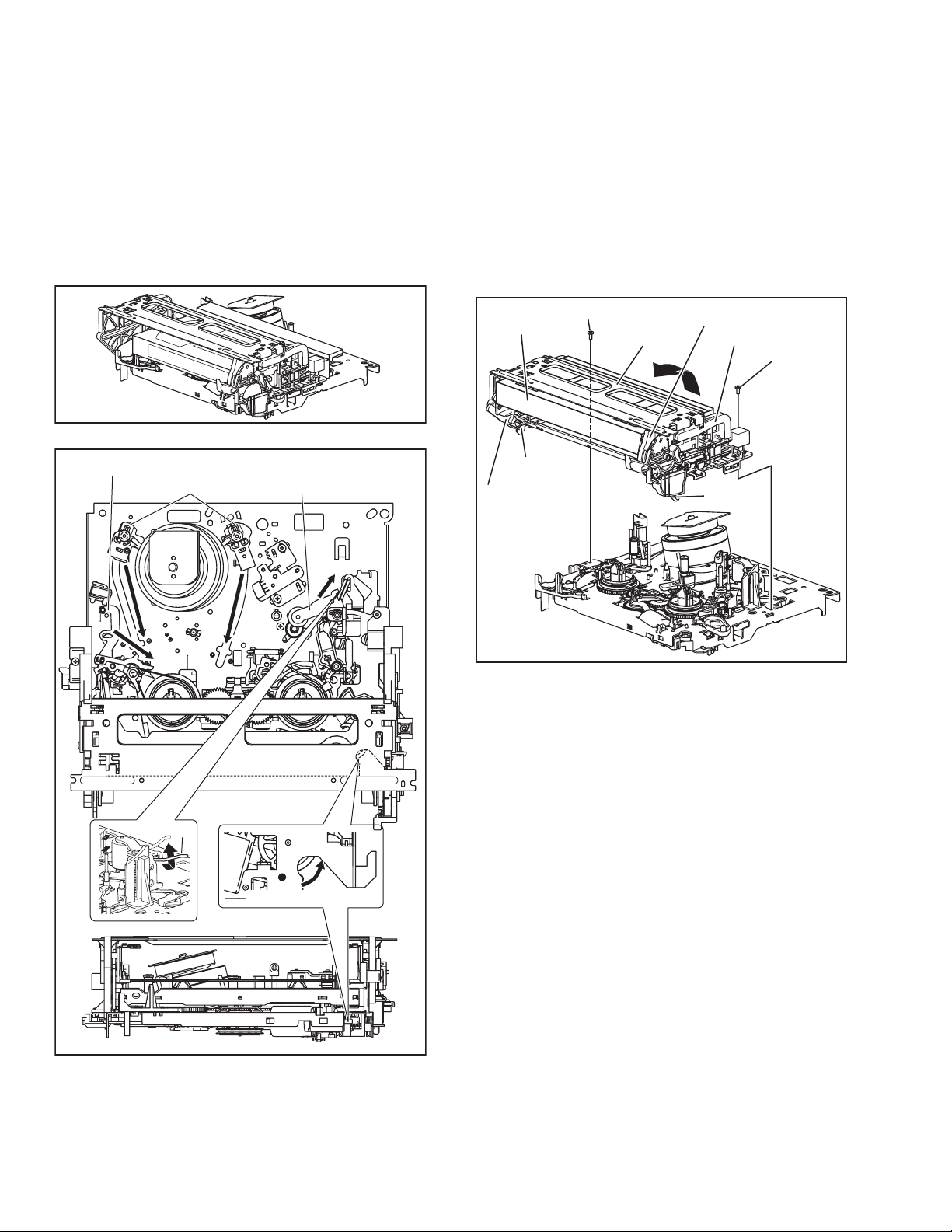
(2) Refer to the disassembly procedure of the unit and perform
the disassembly of the major parts before removing the
mechanism assembly. (See Fig. 5-1a)
Fig.5-1a
Tension arm assembly
Pole base assembly
Pinch roller arm assembly
sion arm assembly free from tension, pull out the tape
on the pole base assembly. Take the spring(a) of the
pinch roller arm assembly off the hook, and detach it
from the tape.
(4) Remove the screw (a) of the side frame (L/R).
(5) Hold the slack tape and cassette cover together, lift the
cassette tape, top frame, cassette holder and side frames
(L, R) together from the rear and remove them by dis-en-
gaging the hooks (a) and (b).
Screw(a)
Cassette tape
Hook(a)
Side frame(L)
Cassette holder
Top frame
Side frame(R)
Screw(a)
Hook(b)
Spring(a)
Direction of unloading
Fig.5-1b
(3) Unload the pole base assembly by manually turning the
gear of the loading motor until the pole base assembly is
hidden behind the cassette lid. In doing so, hold the tape by
the hand to keep the slack away from any grease. (See
Fig.5-1b )
In case of mechanical failures, while keeping the ten-
Fig.5-1c
(6) Take up the slack of the tape into the cassette. This com-
pletes removal of the cassette tape.
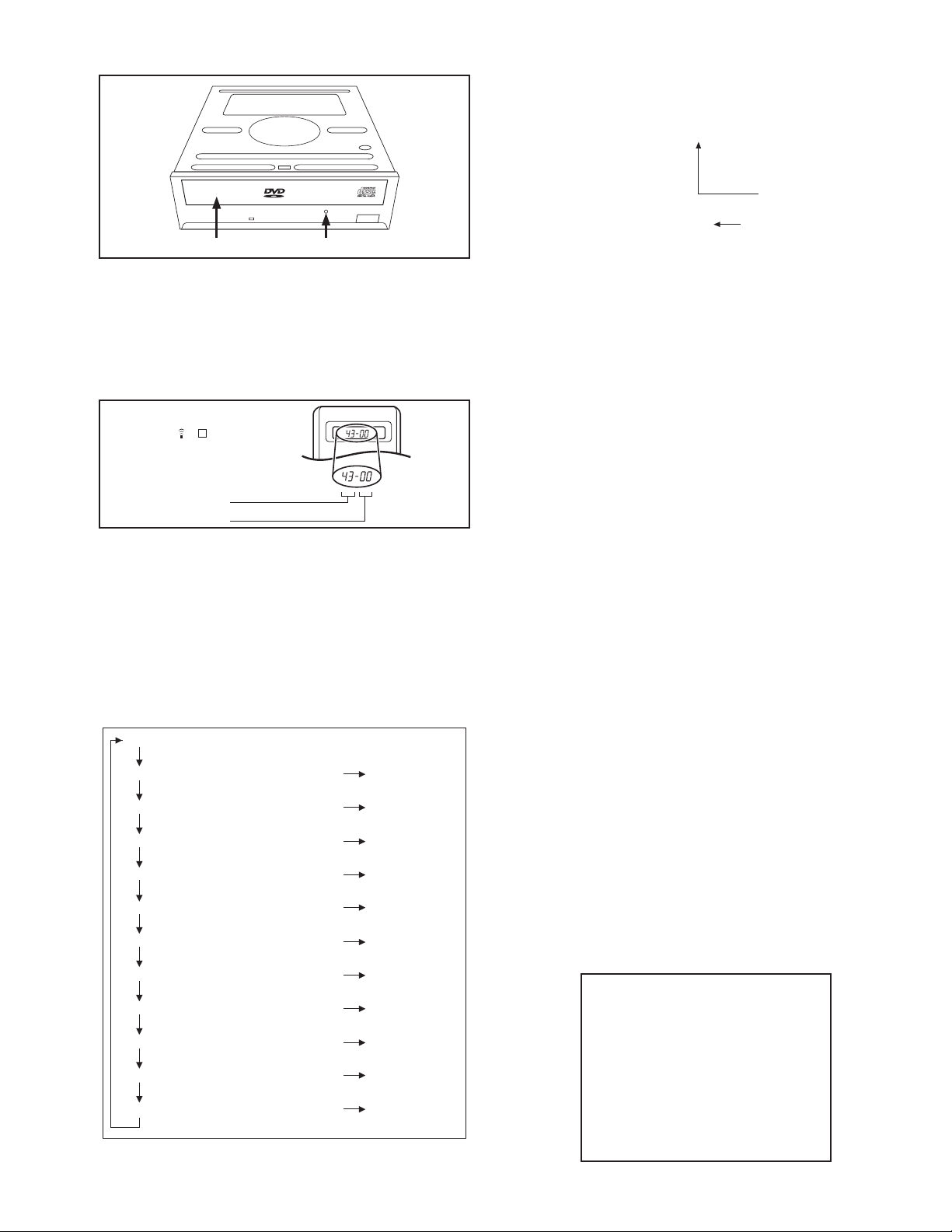
5.2 Manually removing the disk(DVD/CD)
If you cannot remove the disk which is loaded because of any
electrical or mechanical failures, manually remove it by taking the
following steps.
5.2.1 Method 1
(1) AC Plug is pulled out at once and inserted again.
(2) It is displayed on FDP as "LOADING", and while it blinks,
pushing the OPEN/CLOSE button is continued.
(3) After a while, a tray opens (About 20 seconds).
(4) After removed a disk, press the OPEN/CLOSE button
again to close the tray.
(5) The "LOADING" blink display of FDP disappears and it will
be in a standby mode.
(6) If the POWER button is pushed, it will usually be operating.
5.2.2 Method 2
(1) Unplug the ACpower cord from the AC outlet.
(2) Remove the top cover and front panel assembly.
(Refer to the disassembly procedure and perform the dis-
assembly of the major parts before removing)
(3) Pass a thin wire through a hole in the DVD unit.
(4) The disc tray comes out slightly. Take out the disc tray
manually.(See Fig.5-2a)
1-18 (No.YD048)
Page 19
EMG display of FDP display mode
(1) Transmit the code “43-59” from the Jig RCU.
The FDP shows the EMG content in the form of “E:**:**”.
<Example 1> E : 01
Latest EMG
disk tray hole
Fig.5-2a
5.3 Emergency display function (VHS SECTION)
This unit saves details of the last two emergencies as the EMG
history and allows the status of the unit and the mechanism of
each emergency to be shown both on the display and as OSD information.
When using the emergency function, it is required to set the unit
to the Jig RCU mode.
Jig RCU
[Data transmitting method]
Depress the " " ( 3 ) button
after the data code is set.
CUSTOM CODE
43: A CODE
DATA CODE
INITIAL MODE
Fig.5-3a Jig RCU [PTU94023B]
5.3.1 Displaying the EMG information
The EMG detail of information can be displayed by transmitting
the code "43-59" from the Jig RCU.
Note:
• Press VHS/HDD/DVD SELECT button on the unit repeat-
edly first so that the VHS lamp lights up on the unit.
• The EMG detail information <1><2> show the informa-
tion on the latest EMG.
It becomes “ - - : - - : - - ” when there is no latest EMG
record.
0: 00
E: **
1E: **
1: *1
2: *2
3: 34
4: *5
5: *6
6: *7
7: *8
8: *9
9: *10
Normal display
EMG content display (Latest) See 5.3.4
EMG content display (Previous) See 5.3.4
EMG detail information <1> See 5.3.5
[Deck operation mode]
EMG detail information <1> See 5.3.5
[Mechanism operation mode]
EMG detail information <1> See 5.3.5
[Mechanism sensor information and Mechanism mode position]
EMG detail information <2> See 5.3.6
[Type of the cassette tape in use <1>]
EMG detail information <2> See 5.3.6
[Winding position of the cassette tape in use]
EMG detail information <2> See 5.3.6
[Type of the cassette tape in use <2> (Winding area)]
EMG detail information <3> See 5.3.7
[Previous deck operation mode]
EMG detail information <3> See 5.3.7
[The deck operation mode of the one before the last]
EMG detail information <3> See 5.3.7
[The deck operation mode of the one prior to one above]
EMG display of 7 FDP display model
Fig.5-3b
<Example 2> E :
No EMG record
(2) Transmit the code “43-59” from the Jig RCU again.
The FDP shows the EMG detail information <1> in the form
of “ *1: *2 : 34 ”.
*1 : Deck operation mode at the moment of EMG
*2 : Mechanism operation mode at the moment of EMG
3- : Mechanism sensor information at the moment of EMG
-4 : Mechanism mode position at the moment of EMG
(3) Transmit the code “43-59” from the Jig RCU once again.
The FDP shows the EMG detail information <2> in the form
of “ *5 : *6 : *7 ”.
*5 : Type of the cassette tape in use <1> .
*6 : Winding position of the cassette tape in use
*7 : Type of the cassette tape in use <2> (Winding area)
(4) Transmit the code “43-59” from the Jig RCU once again.
The FDP shows the EMG detail information <3> in the form
of “*8 : *9 : *10”.
*8 : Previous deck operation mode at the moment of EMG
*9 : The deck operation mode of the one before the last at
the moment of EMG
*10: The deck operation mode of the one prior to one
above at the moment of EMG
(5) Transmit the code “43-59” from the Jig RCU once again to
reset the display.
5.3.2 Clearing the EMG history
(1) Display the EMG history.
(2) Transmit the code “43-36” from the Jig RCU.
(3) Reset the EMG display.
5.3.3 Details of the OSD display in the EMG display mode
During the EMG display, the OSD shows the data on the deck
mode, etc. The details of the display contents are as follows.
Notes:
• The display is variable depending on the part No. of the
System Control microcomputer (IC3001) built into the
VCR. In the following, refer to the figure carrying the
same two characters as the top two characters of the
part number of your IC.
• The sensor information in the OSD display contents is
partially different from the mechanism sensor information in EMG detail information <1>.
[For MN* only]
AA BB CC DD EE
FF GG HH I I J J
KK L L MM NN OO
PP QQ RR SS TT
UU VV WW XX YY
(No.YD048)1-19
Page 20
AA : Deck operation mode (See EMG detail information <1>.)
BB : Mechanism operation mode
(See EMG detail of information <1>.)
CC : Mechanism transition flag
DD : Capstan motor control status
EE : Loading motor control status
FF : Sensor information (See sensor information details.)
GG : Capstan motor speed
HH : Key code (JVC code)
I I : Supply reel winding diameter data higher 8 bits.
JJ : Supply reel winding diameter data lower 8 bits.
KK : Mechanism sensor information & mechanism mode posi-
tion(See EMG detail of information <1>.)
LL : Tape speed data higher 8 bits.
MM : Tape speed data lower 8 bits.
NN : Cassette tape type <2> higher 8 bits.
(See EMG detail of information <2>.)
OO : Cassette tape type <2> lower 8 bits.
(See EMG detail of information <2>.)
PP : General data display area
YY : General data display area
*FF:Sensor information details
<Display>
** h
********
Encoder data
(See Mechanism mode sequence.)
Cassette tab present = 1
Cassette tab broken = 0
Cassette absent = 1
Cassette present = 0
Start sensor
End sensor
[For *HD only]
<Display>
** h
********
Encoder data
(See Mechanism mode sequence.)
Remote pause
End sensor
Start sensor
Cassette tab present = 1
Cassette tab broken = 0
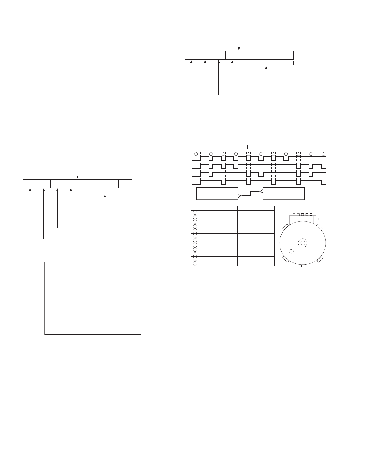
[For both MN*/HD*]
Mechanism mode sequence
Mechanism mode - Encoder data
LSA
LSB
LSC
LSD
No. Position Encoder data
21
Encoder output Low
or
Trerminal GND SHORT
1
EJECT 0 h = 0000
2
EJECT1 1 h = 0001
3
EJECT2 2 h = 0010
4
ULSTOP 3 h = 0011
5
UPPER 4 h = 0100
6
ONSTOP(PLAY) 5 h = 0101
7
FWD/SS 6 h = 0110
8
REV/SS 7 h = 0111
9
OFFSTOP 8 h = 1000
10
FFREW-BRAKE 9 h = 1001
FFREW A h = 1010
11
MIDDLE F h = 1111
12
543
Encoder output High
Trerminal GND OPEN
LSA
12345
1110
GND
9876
or
LSB
LSD
LSC
AA BB CC
DD EE FF
GGGG HHHH
I I JJJJ
KKKK LLLL MMMM
ROM No.
AA : Key code (JVC code)
BB : Deck operation mode(See EMG detail information
<1>.)
CC : Mechanism operation mode (See EMG detail informa-
tion <1>.)
DD : Sensor information (See sensor information details.)
EE : Capstan motor speed (Search, double speed)
FF : Tracking value
GGGG : Cassette tape type <2>, 16 bits.
(See EMG detail information <2>.)
HHHH : Supply reel winding diameter data
I I : Capstan motor speed (FF/REW, double speed)
JJJJ : Tape speed data, lower 8 bits.
KKKK : General data display area
LLLL : General data display area
MMMM : General data display area
*DD:Sensor information details
1-20 (No.YD048)
Page 21

5.3.4 EMG content description
Note:
EMG contents “E09” are for the model with Dynamic Drum (DD).
FDP CONTENT CAUSE
E01: Loading EMG
E02:
Unloading EMG
E03: Take Up Reel
Pulse EMG
E04: Drum FG EMG
E05: Cassette Eject
EMG
E06: Capstan FG
EMG
E07: SW Power
Short-Circuit
EMG
E08:
DVD EMG
E09: DD FG EMG
E0A: Supply Reel
Pulse EMG
EU1:
Head clog warning
history
If the mechanism mode does not change to the next mode within 4 seconds after the loading motor starts rotating in the loading direction, while
the mechanism is in the after-loading position (with the tape up against
the pole base), [E:01] is identified and the power is switched OFF.
However, if the tape loading is not completed within 4 seconds after
the loading motor starts rotating in the loading direction, the tape is
simply unloaded and ejected. No EMG data is recorded in this case.
When the mechanism mode cannot be changed to another mode
even when the loading motor has rotated for more than 4 seconds in the unloading direction, [E:02] is identified and the power
is turned off.
When the falling edje of the take-up reel pulse has not been generated for more than 4 seconds in the capstan rotating mode,
[E:03] is identified, the pinch rollers are turned off and stopped,
and the power is turned off. In this case, however, the mechanism should be in position after tape loading. Note that the reel
EMG is not detected during Slow/Frame advance operations.
When the drum FG pulse has not been input for more than 3 seconds in the drum rotating mode, [E:04] is identified, the pinch rollers are turned off and stopped, and the power is turned off.
If the cassette does not reach the eject position within about 0.7
seconds after the cassette housing has started the cassette ejection operation, [E:05] is identified, the drive direction is reversed
to load the tape, the mode is switched to STOP mode with the
pinch roller OFF, and the power is switched OFF.
During the cassette insertion process, the drive direction is reversed
and the cassette is ejected if the tape is not up against the pole
base within about 3 seconds after the start of the cassette pullingin operation. If the cassette does not reach the eject position within
about 0.7 seconds after the drive mode reversal operation, [E:05]
is identified and the power is switched OFF immediately.
When the capstan FG pulse has not been generated for more
than 1 second in the capstan rotating mode, [E:06] is identified,
the pinch rollers are turned off and stopped, and the power is
turned off.However, the capstan EMG is not detected in SLOW/
STILL modes.
Note that, if the part number of the System Control IC begins with
"MN" or "M3", the capstan EMG is not detected even during the
FF/REW operation.
When short-circuiting of the SW power supply with GND has lasted
for 0.5 second or more, [E:07] is identified, all the motors are
stopped and the power is turned off.
When communication with a system computer of VHS side is not
carried out because of the defective DVD unit, or when the DVD
unit must be reset
When the DD FG pulse is not generated within 2.5 seconds, [E:09]
is identified, the tilt motor is stopped and the power is turned off.
When the falling edge of the supply reel pulse has not been generated for more than 10 seconds in the capstan rotating mode,
[E:0A] is identified and the cassette is ejected (but the power is
not turned off). In this case, however, the mechanism should be
in the position after tape loading (with the tape up against the pole
base). Also note that the reel EMG is not detected during Slow/
Frame advance operations.
Presupposing the presence of the control pulse output in the PLAY mode, when the value obtained by mixing the two V.FM output channels (without regard
to the A.FM output) has remained below a certain threshold level for more than 10 seconds, [E:U1] is identified and recorded in the emergency history.
During the period in which the head clog is detected, the FDP shows "U:01" and the OSD repeats the "3 seconds of warning display" and the "7 seconds of
noise picture display" alternately.
EMG code : "E:C1" or "E:U1" / FDP : "U:01" / OSD : "Try cleaning tape." or "Use cleaning cassette."
The head clog warning is reset when the above-mentioned threshold has been exceeded for more than 2 seconds or the mode is changed to another mode
than PLAY.
1. The mechanism is locked in the middle of the mode transition during a tape loading operation.
2.
The mechanism overruns during the tape loading operation because the SYSCON cannot recognize
the mechanism mode normally. This problem is due to a cause such as a rotary encoder failure.
3.
Power is not supplied to the loading MDA. (M12V/Vcc/Vref/ICP are disconnected in the middle.)
1.
The mechanism is locked in the middle of mode transition.
2.
Without an eject signal being sent from the SYSCON, unloading is attempted (i.e. Ejection is attempted
while the tape is still inside the mechanism.) because the SYSCON cannot recognize the mechanism
mode normally. This is due to a cause such as a rotary encoder failure. (Mechanism position:
UPPER)
3.
Power is not supplied to the loading MDA. (M12V/Vcc/Vref/ICP are disconnected in the middle.)
1.
The take-up reel pulse is not generated in the FWD transport modes (PLAY/FWD SEARCH/FF,
etc.) because;
1) The idler gear is not meshed with the take-up reel gear because the mechanism mal-functions for
2)
3) The reel is rotating normally but an FG pulse is not generated due to the take-up reel sensor failure.
2.
The supply reel pulse is not generated in the REV transport modes (REV SEARCH/REW, etc.)
because;
1) The idler gear is not meshed with the supply reel gear because the mechanism mal-functions for
2) The idler gear is meshed with the supply reel gear, but incapable of winding due to too large a
3) The reel rotates normally but the FG pulse is not generated due to a supply reel sensor failure.
3.
Power(SW5V) is not supplied to the reel sensor on the tape winding side.
1.
The drum could not start or the drum rotation has stopped due to too large a load on the tape,
because;
1) The tape tension is abnormally high;
2) The tape is damaged or a foreign object (grease, etc.) adheres to the tape.
2.
The drum FG pulse did not reach the System controller CPU because;
1) The signal circuit is disconnected in the middle;
2) The FG pulse generator (hall device) of the drum is faulty.
3.
The drum control voltage (DRUM CTL V) is not supplied to the MDA.
4.
Power (M12V) is not supplied to the drum MDA.
1.
The cassette cannot be ejected due to a failure in the drive mechanism of the housing.
2.
When the housing load increases during ejection, the loading motor is stopped because of lack of
headroom in its drive torque.
3.
The sensor/switch for detecting the end of ejection are not functioning normally.
4.
The loading motor drive voltage is lower than specified or power (M12V) is not supplied to the
motor (MDA).
5.
When the user attempted to eject a cassette, a foreign object (or perhaps the user's hand) was
caught in the opening of the housing.
1.
The capstan could not start or the capstan rotation has stopped due to too large a load on the tape,
because;
1) The tape tension is abnormally high (mechanical lock);
2) The tape is damaged or a foreign object (grease, etc.) is adhered to the tape (occurrence of tape
2.
The capstan FG pulse did not reach the System controller CPU because;
1) The signal circuit is disconnected in the middle;
2) The FG pulse generator (MR device) of the capstans is faulty.
3.
The capstan control voltage (CAPSTAN CTL V) is not supplied to the MDA.
4.
Power (M12V, SW5V) are not supplied to the capstan MDA.
1.
The SW 5 V power supply circuit is shorted with GND.
2.
The SW 12 V power supply circuit is shorted with GND.
1. The DVD unit is defective.
2. Contact failure of the wires in the DVD unit or VHS side.
1. The FG sensor is defective. (The soldered parts have separated.)
2. The pull-up resistor at the FG sensor output is defective. (The soldered parts have separated.)
3. Contact failure or soldering failure of the pins of the connector (board-to-board) to the FG sensor.
4. The power (5V) to the sensor is not supplied. (Connection failure/soldering failure)
5. The FG pulse is not sent to the System Controller CPU.
6.
The tilt motor is defective. (The soldered parts have separated.)
7. The drive power to the tilt motor is not supplied. (Connection failure/soldering failure)
8. The tilt motor drive MDA - IC is defective.
9. Auto-recovery of the DD tilting cannot take place due to overrun.
1.
The supply reel pulse is not generated in the FWD transport mode (PLAY/FWD SEARCH/FF,
etc.) because;
1) PLAY/FWD or SEARCH/FF is started while the tape in the inserted cassette is cut in the middle;
2) A mechanical factor caused tape slack inside and outside the supply reel side of the cassette shell.
3) The reel is rotating normally but the FG pulse is not generated due to a supply reel sensor failure.
2.
The take-up reel pulse is not generated in the REV transport mode (REV SEARCH/REW, etc.).
1) REV SEARCH/REW is started when the tape in the inserted cassette has been cut in the middle;
2) A mechanical factor caused tape slack inside and outside the take-up reel side of the cassette
3) The reel is rotating normally but the FG pulse is not generated due to a take-up reel sensor failure.
3.
The power (SW 5V) to a reel sensor is not supplied.
some reason.
The idler gear is meshed with the take-up reel gear, but incapable of winding due to too large
mechanical load (abnormal tension);
some reason.
mechanical load (abnormal tension);
Housing load increasing factors: Temperature environment (low temperature, etc.), mechanism
wear or failure.
entangling, etc.).
In this case, the supply reel will not rotate until the tape slack is removed by the FWD transport,
so the pulse is not generated until then;
shell. In this case, the take up will not rotate until the tape slack is removed by the REV transport,
so the pulse will not be generated until that time;
(No.YD048)1-21
Page 22
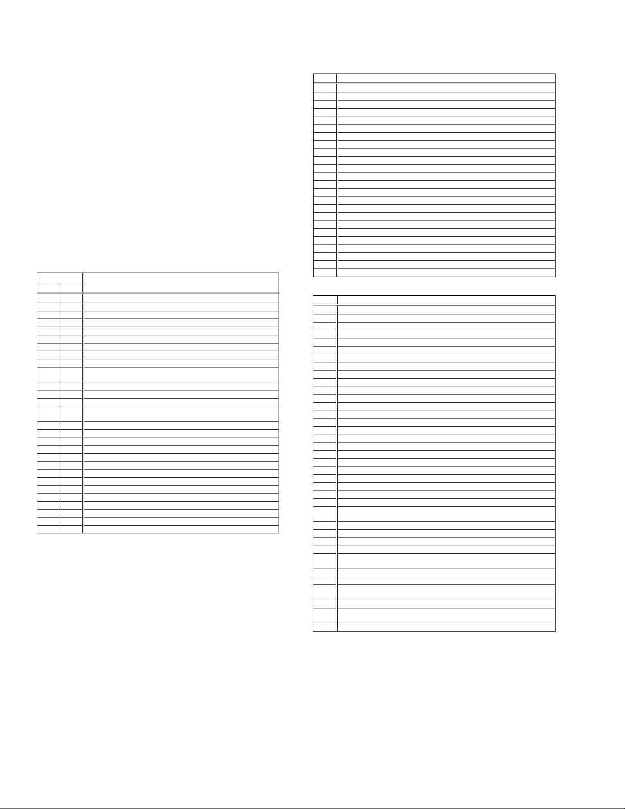
5.3.5 EMG detail information <1>
The status (electrical operation mode) of the VCR and the status
(mechanism operation mode/sensor information) of the mechanism in the latest EMG can be confirmed based on the figure in
EMG detail information <1> .
[FDP/OSD display] *1 : *2 : 34
*1 : Deck operation mode at the moment of EMG
*2 : Mechanism operation mode at the moment of EMG
3- : Mechanism sensor information at the moment of EMG
-4 : Mechanism mode position at the moment of EMG
Note:
• For EMG detailed information <1>, the content of the
code that is shown on the display (or OSD) differs depending on the parts number of the system control microprocessor (IC3001) of the VCR. The system control
microprocessor parts number starts with two letters, refer these to the corresponding table.
*1 : Deck operation mode
[Common table of MN* and HD]
Display
MN* HD*
00 - Mechanism being initialized
01 00 STOP with pinch roller pressure off (or tape present with P.OFF)
02 01 STOP with pinch roller pressure on
03 - POWER OFF as a result of EMG
04 04 PLAY (Normal playback)
0C 0E REC
10 11 Cassette ejected
20 22 FF
21 - Tape fully loaded, START sensor ON, short FF
22 -
24 26 FWD SEARCH (variable speed) including x2-speed
2C 2E INSERT REC
40 43 REW
42 - Cassette identification REV SEARCH before transition to REW
44 47 REV SEARCH (variable speed)
4C 4C AUDIO DUB
6C 6E INSERT REC (VIDEO + AUDIO)
84 84 FWD STILL / SLOW
85 85 REV STILL / SLOW
8C 8F REC PAUSE
8D - Back spacing
8E - Forward spacing (FWD transport mode with BEST function)
AC AF INSERT REC PAUSE
AD - INSERT REC back spacing
CC CD AUDIO DUB PAUSE
CD - AUDIO DUB back spacing
EC EF INSERT REC (VIDEO + AUDIO) PAUSE
ED - INSERT REC (VIDEO + AUDIO) back spacing
Cassette identification FWD SEARCH before transition to FF
(SPx7-speed)
(SPx7-speed)
Deck operation mode
*2 : Mechanism operation mode
[Table of MN*]
Display
00 Command standby (No command to be executed)
01 Immediate Power OFF after EMG occurrence
02 Loading from an intermediate position during mechanism initialization
03 Unloading due to EMG occurrence during mechanism initialization
04 Ejecting cassette (ULSTOP to EJECT)
05 Inserting cassette (EJECT to ULSTOP)
06 Loading tape (ULSTOP to PLAY)
07 Unloading tape (PLAY to ULSTOP)
08 Transition from pinch roller ON to STOP
09 Transition from pinch roller OFF to STOP (PLAY to OFFSTOP)
0A Transition from pinch roller OFF to STOP at power OFF
0B Transition from pinch roller ON to STOP at power ON
0C Transition to PLAY
0D Transition to Search FF
0E Transition to REC
0F Transition to FWD STILL/SLOW
10 Transition to REV STILL/SLOW
11 Transition to Search REV
12 Transition from FF/REW to STOP
13 Transition to FF
14 Transition to REW
15 Tape end detection processing during loading
16 Short FWD/REV at tape sensor ON during unloading
17 Transition to FF/REW brake mode
Mechanism operation mode
[Table of HD*]
Display
00 STOP with pinch roller pressure off
01 STOP with pinch roller pressure on
02 U/L STOP (or tape being loaded)
04 PLAY (Normal playback)
05 PLAY (x1-speed playback using JOG)
0E REC
11 Cassette ejected
22 FF
26 FWD SEARCH (variable speed) including x2-speed
2E INSERT REC
43 REW
47 REV SEARCH
4C AUDIO DUB
6E INSERT REC (VIDEO + AUDIO)
84 FWD STILL/SLOW
85 REV STILL/SLOW
8F REC PAUSE
AF INSERT REC PAUSE
C7 REV SEARCH (x1-speed reverse playback using JOG)
CD AUDIO DUB PAUSE
EF INSERT REC (VIDEO + AUDIO) PAUSE
F0 Mechanism being initialized
F1 POWER OFF as a result of EMG
F2 Cassette being inserted
F3 Cassette being ejected
F4 Transition from STOP with pinch roller pressure on to STOP with pinch
roller pressure off
F5 Transition from STOP with pinch roller pressure on to PLAY
F6 Transition from STOP with pinch roller pressure on to REC
F7 Cassette type detection SEARCH before FF/REW is being executed
F8 Tape being unloaded
F9 Transition from STOP with pinch roller pressure off to STOP with pinch
roller pressure on
FA Transition from STOP with pinch roller pressure off to FF/REW
FB Transition from STOP with pinch roller pressure off to REC.P (T.REC,etc.)
FC Transition from STOP with pinch roller pressure off to cassette type
detection SEARCH
FD Short REV being executed after END sensor on during unloading
FE Tension loosening being executed after tape loading (STOP with pinch
roller pressure on)
FF Tape being unloaded
Mechanism operation mode
1-22 (No.YD048)
Page 23
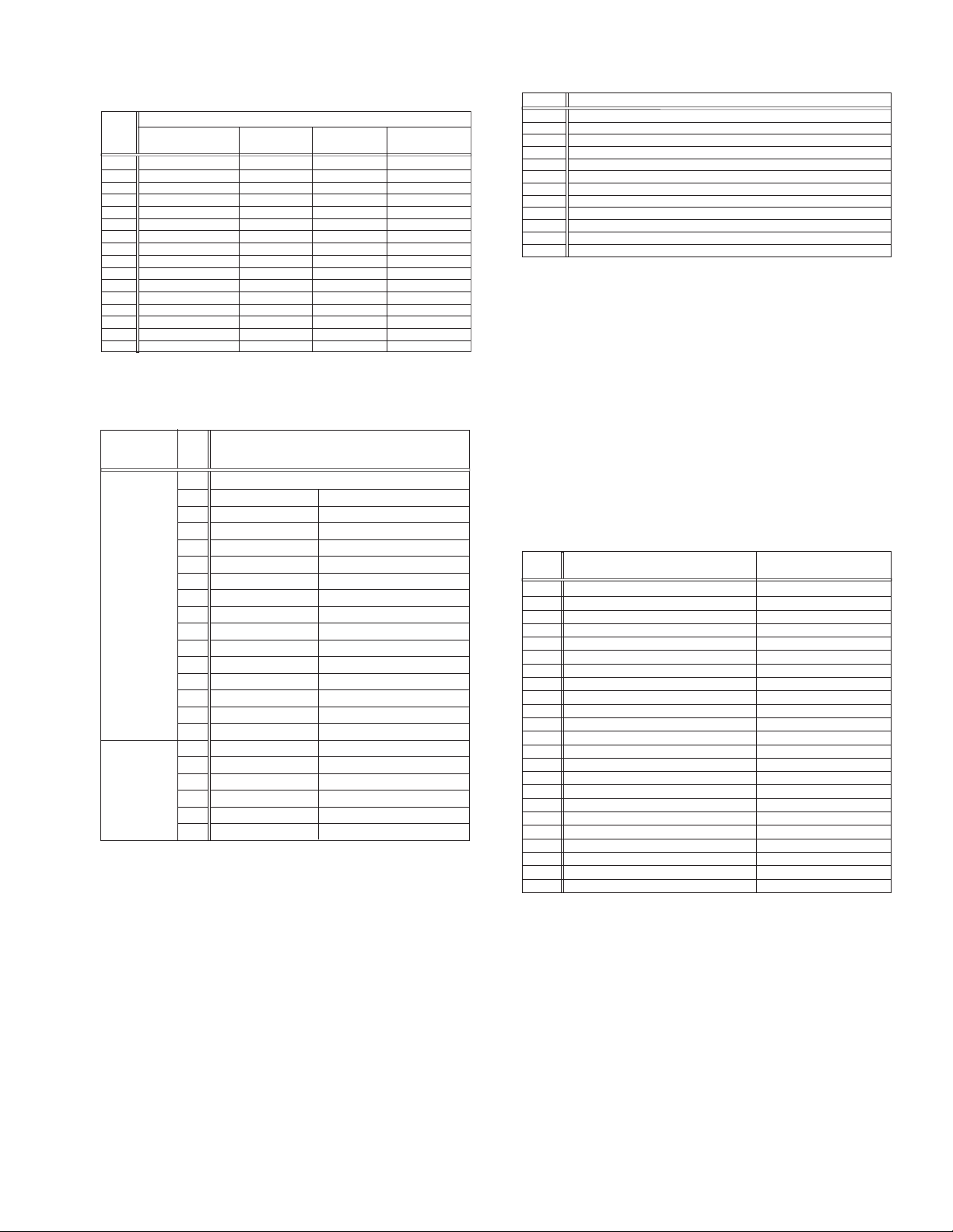
3- : Mechanism sensor information
[Common table of MN* and HD*]
Display
A- Tab broken
B- Tab broken OFF
C- Tab present ON
D- Tab present
E- Tab present OFF
REC safety SW
0- Tab broken ON ON ON
1- Tab broken ON
2- Tab broken ON
3- Tab broken ON OFF
4- Tab present ON
5- Tab present
6- Tab present OFF
7- Tab present OFF
8- Tab broken ON ON
9- Tab broken ON
F- Tab present OFF
Tab broken = 0 Sensor ON = 0 Sensor ON = 0
Tab present = 1 sensor OFF = 1 Sensor OFF = 1
Mechanism sensor informatio n
Start sensor End sensor
ON
OFF
OFF
OFF
ON
ON
OFF
OFF
ON
OFF
OFF
ON
OFF
ON
OFF
OFF OFF
Mechansim
position sensor
OFF
ON
OFF
ON
OFF
ON
OFF
ON
OFF
ON
OFF
ON
OFF
ON
-4 : Mechanism mode position
[Common table of MN* and HD*]
Mechanism
sensor
information
Dis
play
Deck operation mode
0 Not established
1 EJECT EJECT position
2 EJECT EJECT1 Intermodal position
3 EJECT1 EJECT1 position
4 EJECT1 EJECT2 Intermodal position
5 EJECT2 EJECT2 position
6 EJECT2 ULSTOP Intermodal position
Even number
(0, 2, 4, 6, 8,
A, C, E)
7 ULSTOP ULSTOP position
8 ULSTOP UPPER Intermodal position
9 UPPER Loading (unloading) tape
A UPPER ONSTOP Intermodal position
B ONSTOP PLAY position
C PLAY FWD/SS Intermodal position
D FWD/SS
FWD (FWD Still/Slow) position
E FWD/SS REV Intermodal position
F REV
REV (REV Still/Slow) position
0 REV OFFSTOP Intermodal position
1 OFFSTOP Pinch roller OFF position
Odd number
(1, 3, 5, 7, 9,
B, D, F)
2
OFFSTOP FFREWB
Intermodal position
3 FFREWB FF/REW Brake position
4 FFREWB FFREW Intermodal position
5 FFREW FF/REW position
5.3.6 EMG detail information <2>
The type of the cassette tape and the cassette tape winding position can be confirmed based on the figure in EMG detail information <2> .
Note:
• EMG detail information <2> is the reference information
stored using the remaining tape detection function of
the cassette tape. As a result, it may not identify cassette correctly when a special cassette tape is used or
when the tape has variable thickness.
*5 : Cassette tape type <1>
Display Cassette tape type <1>
00 Cassette type not identified
16
Large reel/small reel (T-0 to T-15/T-130 to T-210) not classified
82 Small reel, thick tape (T-120) identified/thin tape (T-140) identified
84 Large reel (T-0 to T-60) identified
92
Small reel, thick tape (T-130) identified/thin tape (T-160 to T-210) identified
93
Small reel, thick tape/C cassette (T-0 to T-100/C cassette) not classified
C3
Small reel, thick tape/C cassette (T-0 to T-100/C cassette) being classified
D3
Small reel, thick tape/C cassette (T-0 to T-100/C cassette) being classified
E1 C cassette, thick tape (TC-10 to TC-20) identified
E2 Small reel, thick tape (T-0 to T-100) identified
E9 C cassette, thin tape (TC-30 to TC-40) identified
F1
C cassette, thick tape/thin tape (TC-10 to TC-40) not classified
Notes:
• Cassette tape type <1> is identified a few times during
mode transition and the identification count is variable
depending on the cassette tape type. If an EMG occurs
in the middle of identification, the cassette tape type
may not be able to be identified.
• If other value than those listed in the above table is dis-
played, the cassette tape type is not identified.
*6 : Cassette tape winding position
The cassette tape winding position at the moment of EMG is displayed by dividing the entire tape (from the beginning to the end)
in 21 sections using a hex number from “00” to “14”.
00 : End of winding
14 : Beginning of winding
FF : Tape position not identified
*7 : Cassette tape type <2> (Winding area)
Display
00
04 - 08
05 - 06
05 - 0C
06 - 0C
06 - 0C
07 - 08
09 - 0B
0C - 0D
0D - 0F
0E - 10
10 - 12
10 - 13
11 - 14
12 - 14
13 - 14
13 - 14
13 - 14
13 - 14
15 - 16
16 - 17
17 - 18
19 - 1B
Cassette tape type <2>
Cassette type not identified
C cassette, thick tape TC-10
Small reel, thick tape T-20
C cassette, thick tape TC-20P
C cassette, thin tape TC-40
C cassette, thin tape TC-30
Small reel, thick tape T-40
Small reel, thick tape T-60
Small reel, thick tape T-80(DF-160)
Small reel, thick tape T-90(DF-180)
Small reel, thick tape T-100
Small reel, thin tape T-140
Small reel, thick tape T-120(DF-240)
Small reel, thick tape T-130
Small reel, thin tape T-160
Small reel, thin tape T-210(DF-420)
Small reel, thin tape T-180(DF-360)
Small reel, thin tape T-168
Small reel, thick tape DF-300
Large reel T-20
Large reel T-30
Large reel T-40
Large reel T-60
(Reference) Word data
(Beginning) (End)
(0497 - 0506) (0732 - 0858)
(05A9 - 0661)
(0599 - 05FF) (0AA1 - 0C07)
(0623 - 063D) (0C41 - 0CC3)
(0611 - 0638) (0C0C - 0CB2)
(07CC - 08E5)
(09FD - 0B78)
(0C20 - 0DFC)
(0D31 - 0F3E)
(0E43 - 107F)
(10E1 - 120C)
(1073 - 1313)
(1185 - 1429)
(12D3 - 141F)
(1373 - 14C3)
(1357 - 14C0)
(1395 - 14EE)
(13A8 - 14CE)
(1536 - 1618)
(1647 - 175A)
(1759 - 189C)
(1989 - 1B2F)
Note:
• The values of cassette tape type <2> in the above table
are typical values with representative cassette tapes.
5.3.7 EMG detail information <3>
Three deck operation modes preceding the deck operation mode
in which the EMG occurs may be confirmed based on the figures
in the EMG information detail <3>. For the contents of the displayed information, see the table "Deck operation mode" in section "5.3.5 EMG detail information <1>".
(No.YD048)1-23
Page 24
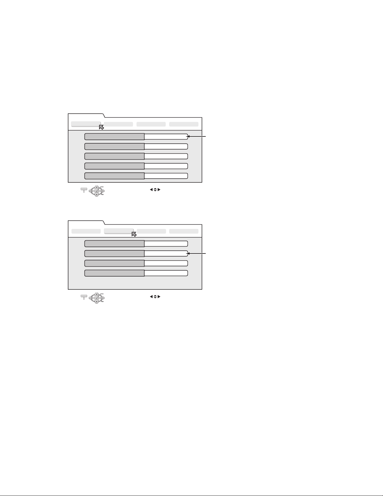
5.4 Display function of DVD section
5.4.1 Displaying SYSTEM INFO
SYSTEM INFO contains information on firmware version of the unit and the mechanism drive, and an initialize execution menu.
(1) Set the unit to the Jig RCU mode.
(2) Press VHS/HDD/DVD SELECT button on the unit repeatedly so that the HDD lamp lights up on the unit.
(3) Transmit "43-8b" from the Jig RCU.
(4) SYSTEM INFORMATION menu is displayed in the screen.
(5) To move cursor in SYSTEM INFO, use the " ", " ", " ", and " " buttons of a remote control unit attached to product.
(6) To quit the SYSTEM INFO menu, transmit "43-8b" from the Jig RCU..
(7) Cancel Jig RCU mode.
The example of a display < Version Info 1 >
System Info
Version Info 1
Version Info 2 NAVI Info Initialize
Application Software Version
Middle Ware Software Version
Syscon Software Version
Boot Loader Software Version
VHS Syscon Software Version
OK
SELECT WITH [ ] THEN PRESS [ENTER]
EXIT
PRESS [ "8b" ] TO EXIT
SELECT
1.04
0835
1.00
1.2 / 191
1.00
The example of a display < Version Info 2 >
System Info
Version Info 1
Silicon Version of E5
DVD Drive Firmware Version
Region
CPRM Key DownLoad
EXIT
NOTE:
Items other than the ones described above are not used in service work.
Version Info 2
OK
SELECT WITH [ ] THEN PRESS [ENTER]
PRESS [ "8b" ] TO EXIT
SELECT
NAVI Info Initialize
C0
P012
2
Done
Firmware Version of the unit
When the Firmware of the unit is updated,
this part is changed.
Firmware Version of the Drive unit
When the Firmware of the drive unit is updated,
this part is changed.
1-24 (No.YD048)
Page 25

5.4.2 Updating the firmware of the unit
• Firmware update disc supports CD-R media.
• When firmware update is necessary, information is available from the homepage of DIGITAL VIDEO STORAGE CATEGORY, CS
group.
5.4.2.1 Creating an update disc
Please check the details of the update disc creation method by JS-NET.
(1) Down load the update file from JS-NET.
(2) Write the update file into CD-R. Pay attention in the following points when writing the update disc.
• Make sure to write in “Disc at Once”.
• Set the file compatibility to “ISO9660 format”. (ROMEO, JOLIET are disapproved.)
If the writing method is not correct, the update results in an error.
5.4.2.2 Update procedure
• There are two methods of updating firmware, using JIG RCU mode <method 1> or not using JIG mode(User update mode) <method
2>.
Updating can be operated in either method.
<Method 1>
(1) Set to the Jig RCU mode.
(2) Press VHS/HDD/DVD SELECT button on the unit repeatedly so that the DVD lamp lights up on the unit.
(3) Load the update disc on the tray, and then close the tray.
(4) When the disc reading operation is completed, transmit “43-70” with the Jig remote control unit.
If the update disc is not correct, FDP indicator displays an “ERROR” after transmitting “43-70”. Transmit “43-70” once and
make the FDP indicator to normal display, and then reload the disc then transmit “43-70” again.
(5) “UPDATE” is displayed in the FDP indicator, and the FDP indicator changes to “FL UPDATE” afterwards. It takes approx. 2
minutes for the change.
(6) Remove the disc as the tray is ejected, and then transmit “43-70” with the Jig remote control unit. Then the FDP indicator
changes from “UPDATE” to the normal display.
(7) Close the tray and turn the unit OFF. Pull out the power code from the wall socket, then plug the power cord into the wall socket
again.
(8) When “LOADING” in the FDP indicator disappears, turn the unit ON.
(9) Display the SYSTEM INFO menu, and check the version of the firmware.
(10) Cancel the Jig RCU mode.
<Method 2>
(1) Turn the power ON. Load the update disc on the tray and close the tray.
(2) When the disc reading operation is completed, turn the power OFF.
(3) Keep pressing the “PAUSE” button and the “POWER” button at the same time. (Until FDP indicator changes to “UPDATE”).
(4) In approx. 2 minutes the tray is ejected. Remove the disc and close the tray.
(5) Reset operation is carried out automatically, and it becomes standby condition.
(6) Then, display the SYSTEM INFO menu in the Jig RCU mode and check the version.
5.4.3 Updating the firmware of the drive unit
• Firmware update disc supports only DVD-RAM media.
• When firmware update is necessary, written discs are distributed by DIGITAL VIDEO STORAGE CATEGORY, CS group.
(1) Turn the unit ON.
(2) Press VHS/HDD/DVD SELECT button on the unit repeatedly so that the DVD lamp lights up on the unit.
(3) Load the update DVD-RAM disc on the tray and close the tray.
(4) “READING” is displayed in the FDP indicator and the update is started.
(5) In a short while “READING” in the FDP indicator disappears, open the tray to remove the disc and close the tray.
(6) Turn the power OFF and pull out the power code from the wall socket, then plug the power cord into the wall socket again.
(7) Set to the Jig RCU mode and check the firmware version of the drive.
(No.YD048)1-25
Page 26
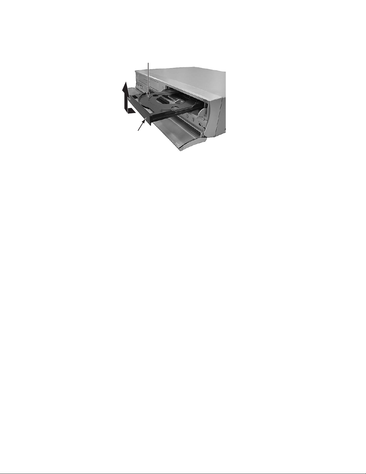
5.4.4 Exchanging the fitting
As the fitting that comes with the service drive unit cannot be used, make sure to attach a service fitting when the drive unit is exchanged. The fitting that is removed from the old drive unit can be attached to the new drive unit.
The fitting can be removed by pulling upwards while opening out the lower part of the fitting outwards.
Tray
Fitting
5.4.5 Initialization to the factory shipment state
When the initialization is operated, internal information changes as follows. It is essential to obtain the client’s permission before the
operation.
• All DVD library is all deleted.
• All the DVD initial settings go back to the initial status.
(1) Set to the Jig RCU mode.
(2) Press VHS/HDD/DVD SELECT button on the unit repeatedly so that the DVD lamp lights up on the unit.
(3) Transmit “43-6F” with the Jig remote control unit.
(4) FDP indicator displays “FACTORY”, and changes to “CHECK OK” after blinking for a short while.
(5) Pull out the power code from the wall socket.
(6) The Jig RCU mode is forced to cancel at the same time with the initialization, check whether the Jig RCU mode is canceled by
plugging the power code into the wall socket again. (The colon “:” in time display should be continuously ON, not blinking.)
If the Jig RCU mode is not canceled, transmit “43-9D” with Jig remote control unit to cancel the Jig RCU mode.
5.4.6 Setting after the drive unit replacement
When the drive unit is replaced, it is necessary to set a region code. Service drive units for replacement are not set for any region
code, and they are in an indefinite condition.
Make sure to set region code after attaching the drive unit to the unit.
Without the setting of the region code, discs that have regions cannot be played back.
5.4.6.1 Creating a region setting disc.
Please check the details of the region setting disc creation method by JS-NET.
(1) Download the region setting file from JS-NET.
(2) Write the region setting file into CD-R. Pay attention in the following points when writing the file into CD-R.
• Make sure to write in “Disc at Once”.
• Set the file compatibility to “ISO9660 format”. (ROMEO, JOLIET are disapproved).
If the writing method is not correct, the normal setting cannot be performed.
5.4.6.2 Setting the region
(1) Set for the Jig RCU mode.
(2) Press VHS/HDD/DVD SELECT button on the unit repeatedly so that the DVD lamp lights up on the unit.
(3) Load the region setting disc on the tray, and then close the tray.
(4) When the disc reading operation is completed, transmit “43-70” with the Jig remote control unit.
(5) FDP indicator changes to “UPDATE”. Remove the disc as the tray will open for a few seconds.
(6) Then, check whether the FDP indicator is “REGION 1”.
(7) Transmit “43-70” with the Jig remote control unit. When FDP indicator changes to “OPEN”, close the tray.
(8) Turn the power OFF, and pull out the power code, and then plug the power code in again.
(9) Cancel the Jig RCU mode.
1-26 (No.YD048)
Page 27

5.4.7 Booting the system using the CD
The firmware of this device is stored in the Hard Disk Drive (HDD). If the firmware is collapsed for its contents, [LOADING] is repeatedly
displayed on the FDP display of the main unit and the system becomes inoperative. The system operation cannot be resumed even
if the AC plug is disconnected from the AC power source.
In such a situation, the operation may be resumed on a temporary basis to normal using a CD that stores the firmware. This causes
the firmware in the HDD to be updated and the system may be brought to a normal operation. Refer to the following descriptions for
detail.
5.4.7.1 Downloading the firmware from JS-NET to create a booting disk
NOTE:
For details of creating the booting disk, see the instructions provided in the JS-NET web site.
(1) Download all the relevant files from the JS-NET and decompress it.
(2) The file termed "bootup1.blx" will accordingly be created. Copy this file in a root directory of the CD-R.
(3) Set the track setting to [MODE2 XA] for writing the software, and select [JOLIET] as an exchangeable file name. Be sure to write
the disk in [Disk at once] mode.
5.4.7.2 Booting using the Disk
The following explanation is made assuming the system operation is being unable with [LOADING] repeatedly displayed.
(1) Disconnect the AC plug and then connect it again. Immediately after this, press and hold the DVD ON/OFF button until the tray
comes out.
(2) Put the booting disk on the tray and close the tray.
(3) Disconnect the AC plug. Press and hold the STOP button and connect the AC plug.
(4) Keep the button pressed for 20 seconds and release the button (Timing must be precise).
(5) [LOADING] will be displayed repeatedly for a while and the system will be brought to the standby state.
(6) Press the OPEN/CLOSE button to remove the booting disk.
(7) Turn the system on and confirm that the operation is normal. If so, the system should be properly booted from the CD-R.
5.4.7.3 Updating the firmware after booting with the CD
By updating the firmware using the CD, the built-in firmware in the HDD will be overwritten, allowing the firmware to be renovated. The
system may be resumed to a normal state using this method. Be sure to download the latest version of the update firmware when you
attempt to create and use the firmware. For the updating procedures, refer to 5.6.
(No.YD048)1-27
Page 28

Victor Company of Japan, Limited
AV & MULTIMEDIA COMPANY DIGITAL VIDEO STORAGE CATEGORY 12, 3-chome, Moriya-cho, kanagawa-ku, Yokohama, kanagawa-prefecture, 221-8528, Japan
(No.YD048)
Printed in Japan
VPT
Page 29
DVD / HDD VIDEO RECORDER &
VIDEO CASSETTE RECORDER
DR-MX1S
TVCB SAT
TV
AV
TV
VIDEO
VHS HDD DVD
AUX
CANC L
MEM / ARK
LI E
PM NU
ENTER
MENU
STOP
JUMP
ECMODE
DSP AY
ONSC EEN
REMAN
CAB E/SAT
VD
TV
S ANDBYON
DVD
PR
PROG AMME
EDTDU BI G
NAVGATONO
RETU N
N XTPREVOUS
S OWSLOW LAY SEL CT
PAUSEREC
SETUP
17
AMRW
INSTRUCTIONS
LPT0976-001B
EN
Page 30
2 EN
SAFETY FIRST
Safety Precautions
The rating plate and the safety caution are on the rear of the unit.
WARNING: DANGEROUS VOLTAGE INSIDE
WARNING: TO PREVENT FIRE OR SHOCK HAZARD,
DO NOT EXPOSE THIS UNIT TO RAIN OR
MOISTURE.
CAUTION:
A UNIT IS A CLASS 1 LASER PRODUCT. HOWEVER THIS
UNIT USES A VISIBLE LASER BEAM WHICH COULD CAUSE
HAZARDOUS RADIATION EXPOSURE IF DIRECTED. BE
SURE TO OPERATE THE UNIT CORRECTLY AS
INSTRUCTED.
WHEN THIS UNIT IS PLUGGED INTO THE WALL OUTLET,
DO NOT PLACE YOUR EYES CLOSE TO THE OPENING OF
THE DISC TRAY AND OTHER OPENINGS TO LOOK INTO
THE INSIDE OF THIS UNIT.
USE OF CONTROLS OR ADJUSTMENTS OR
PERFORMANCE OF PROCEDURES OTHER THAN THOSE
SPECIFIED HEREIN MAY RESULT IN HAZARDOUS
RADIATION EXPOSURE.
DO NOT OPEN COVERS AND DO NOT REPAIR YOURSELF.
REFER SERVICING TO QUALIFIED PERSONNEL.
CLASS 1 LASER PRODUCT
REPRODUCTION OF LABELS
WARNING LABEL INSIDE OF THE UNIT
IMPORTANT:
8 Please read the various precautions on page 2 and 3 before
installing or operating the unit.
8 It should be noted that it may be unlawful to re-record pre-
recorded tapes, DVDs, or discs without the consent of the
owner of copyright in the sound or video recording,
broadcast or cable programme and in any literary, dramatic,
musical, or artistic work embodied therein.
CAUTION:
8 When you are not using the unit for a long period of time, it is
recommended that you disconnect the power cord from the
mains outlet.
8 Dangerous voltage inside. Refer internal servicing to
qualified service personnel. To prevent electric shock or fire
hazard, remove the power cord from the mains outlet prior to
connecting or disconnecting any signal lead or aerial.
● Manufactured under licence from Dolby Laboratories. ADolbyB and double-D symbol are trademarks of Dolby Laboratories.
● ADTSB and ADTS DIGITAL OUTB are trademarks of Digital Theater Systems, Inc.
● a is a trademark of Gemstar Development Corporation. The a system is manufactured under license from Gemstar
Development Corporation.
● This product incorporates copyright protection technology that is protected by method claims of certain U.S. patents and other intellectual
property rights owned by Macrovision Corporation and other rights owners. Use of this copyright protection technology must be
authorized by Macrovision Corporation, and is intended for home and other limited viewing users only unless otherwise authorized by
Macrovision Corporation. Reverse engineering or disassembly is prohibited.
Page 31

For Italy:
AIt is declared that this product, brand JVC, conforms to the
Ministry Decree n. 548 of 28 Aug.’95 published in the Official
Gazette of the Italian Republic n. 301 of 28 Dec.’95B
The STANDBY/ON A button does not completely shut off
mains power from the unit, but switches operating current on
and off. ABB shows electrical power standby and ACB shows ON.
When the equipment is installed in a cabinet or a shelf, make sure
that it has sufficient space on all sides to allow for ventilation
(10 cm or more on both sides, on top and at the rear).
When discarding batteries, environmental problems must be
considered and the local rules or laws governing the disposal of
these batteries must be followed strictly.
Failure to heed the following precautions may result in
damage to the unit, remote control or disc.
1. DO NOT
^ in an environment prone to extreme temperatures or
^ in direct sunlight.
^ in a dusty environment.
^ in an environment where strong magnetic fields are
^ on a surface that is unstable or subject to vibration.
2. DO NOT
(If the ventilation openings or holes are blocked by a
newspaper or cloth, etc., the heat may not be able to get out.)
3. DO NOT
4. DO NOT
or remote control.
(If water or liquid is allowed to enter this equipment, fire or
electric shock may be caused.)
5. DO NOT
6. DO NOT
water. Also DO NOT place any containers filled with water or
liquids (such as cosmetics or medicines, flower vases, potted
plants, cups, etc.) on top of this unit.
7. DO NOT
candles, on the apparatus.
8. AVOID
place the unit ^
humidity.
generated.
block the unit’s ventilation openings or holes.
place heavy objects on the unit or remote control.
place anything which might spill on top of the unit
expose the apparatus to dripping or splashing.
use this equipment in a bathroom or places with
place any naked flame sources, such as lighted
violent shocks to the unit during transport.
SAFETY FIRST
EN 3
MOISTURE CONDENSATION
Moisture in the air will condense on the unit when you move it from
a cold place to a warm place, or under extremely humid
conditions^just as water droplets form on the surface of a glass
filled with cold liquid. In conditions where condensation may occur,
disconnect the unit’s power plug from the wall and keep it
disconnected for a few hours to let the moisture dry, then turn on
the unit.
ATTENTION:
To mobile phone users:
Using a mobile phone in the vicinity of the unit may cause picture
vibration on the TV screen or change the screen to a blue back
display.
On placing the unit:
Some TVs or other appliances generate strong magnetic fields.
Do not place such appliances on top of the unit as it may cause
picture disturbance.
When moving the product:
Press A to turn off the power, and wait at least 30 seconds
before unplugging the power cord. Then, wait at least 2 minutes
before moving the product.
HOW TO USE THIS INSTRUCTION MANUAL
● All major sections and subsections are listed in the Table Of
Contents on page 4. Use this when searching for information on
a specific procedure or feature.
● The Index on pages 10 – 13 illustrates the controls and
connections on the front and rear panel, the front display panel
and the remote control.
● The list of terms on page 99 lists frequently-used terms, and the
number of the page on which they are used or explained in the
manual.
● The A mark signals a reference to another page for instructions
or related information.
● Operation buttons necessary for the various procedures are
clearly indicated through the use of illustrations at the beginning
of each major section.
Page 32

4 EN
CONTENTS
SAFETY FIRST 2
Safety Precautions.........................................................................2
DISC INFORMATION 5
About Discs....................................................................................5
INDEX 10
INSTALLING YOUR NEW UNIT 16
Basic Connections .......................................................................16
INITIAL SETTINGS 17
Auto Set Up..................................................................................17
Preset Download..........................................................................18
Language .....................................................................................20
Monitor Set...................................................................................21
SAT CONTROL SET 22
Satellite Receiver Control Setting
(HDD & DVD Deck Only)...........................................................22
BASIC OPERATIONS ON DVD DECK 24
Basic Playback.............................................................................24
Playback Features .......................................................................25
Using The On-screen Bar ............................................................29
Parental Lock ...............................................................................33
Basic Recording...........................................................................34
Recording Features......................................................................35
BASIC OPERATIONS ON HDD DECK 37
Basic Recording...........................................................................37
Recording Features......................................................................38
Basic Playback.............................................................................39
Playback Features .......................................................................39
BASIC OPERATIONS ON VHS DECK 41
Basic Playback.............................................................................41
Playback Features .......................................................................42
Basic Recording...........................................................................44
Recording Features......................................................................44
LIVE MEMORY PLAYBACK ON HDD/DVD DECK 46
Live Memory Playback.................................................................46
TIMER RECORDING ON HDD/DVD DECK 49
c Timer Programming ....................................................49
Manual Timer Programming.........................................................51
Automatic Satellite Programme Recording
(HDD Deck Only).......................................................................53
TIMER RECORDING ON VHS DECK 54
b Timer Programming.................................................... 54
Manual Timer Programming ........................................................ 55
NAVIGATION ON HDD/DVD DECK 57
Library Database Navigation .......................................................57
Edit Original Information .............................................................. 58
Edit Play List Information............................................................. 60
Edit Library Information ............................................................... 62
Playback With MP3/WMA/JPEG Navigation ...............................63
EDITING 64
Dubbing .......................................................................................64
DV Dubbing (HDD & DVD Deck Only) ........................................ 68
Edit From A Camcorder............................................................... 70
Edit To Or From Another Recorder ............................................. 71
Output/Input Set .......................................................................... 72
Digital Audio Dubbing .................................................................. 73
REMOTE CONTROL 74
Remote Control Functions........................................................... 74
SYSTEM CONNECTIONS 76
Connecting To A Satellite Receiver............................................. 76
Connecting To A Dolby Digital Decoder Or
An Amplifier With Built-in DTS .................................................. 77
Connecting/Using A Decoder
(HDD & DVD Deck Only) .......................................................... 77
SUBSIDIARY SETTINGS 78
Mode Set (HDD & DVD Deck Only) ............................................ 78
Mode Set (VHS Deck Only)......................................................... 81
Tray Lock (DVD Deck Only) ........................................................ 82
c System Setup ............................................................. 83
Tuner Set..................................................................................... 83
Clock Set .....................................................................................86
Format A Disc (DVD Deck Only) .................................................87
Finalise A Disc (DVD Deck Only) ................................................88
Scan Mode Set ............................................................................ 89
TROUBLESHOOTING 90
SPECIFICATIONS 94
APPENDIX 95
LIST OF TERMS 99
Page 33

About Discs
Recordable/Playable Discs
You can use discs with the following logos for recording and
playback.
DVD-RAM
12 cm: 4.7 GB/9.4 GB
8 cm: 1.4 GB/2.8 GB
Ver. 2.0/2x speed
Ver. 2.1/1x – 3x speed
DVD-R
12 cm: 4.7 GB
8 cm: 1.4 GB
Ver. 2.0/1x – 4x/8x speed
(Video mode)
● The above table is based on the information as of October 2004.
● Recording and playback may not be performed depending on the
characteristics and condition of the disc used, leading to
unsatisfactory results. Using discs manufactured by JVC is
recommended since they have been tested to be compatible with
this unit.
DVD-RAM Discs
It is only possible to use discs which conform with DVD-RAM
standard Version 2.0 or 2.1.
● It is impossible to record on DVD-RAM discs which do not
conform to this standard. If you use a disc formatted under a
different standard version, format it on this unit before use.
● It may not be possible to record, play back, edit or dub a
DVD-RAM disc even if it conforms to the standard if it was
recorded or edited on the devices from other manufacturers or on
a PC, or if it has far too many titles, or if there is very little
available capacity remaining on the disc.
● DVD-RAM discs recorded on this unit cannot be played back on
an incompatible DVD player.
● It is possible to record copy-once programmes of digital
broadcasts only onto 4.7/9.4 GB DVD-RAM discs (2.8 GB
DVD-RAM discs are not compatible).
● Although this unit supports 3x speed DVD-RAM discs, dubbing
cannot be achieved at 3x speed.
DVD-RW
12 cm: 4.7 GB/9.4 GB
Ver. 1.1/1x – 2x speed
(Video mode/VR mode)
Ver. 1.2/4x speed
(Video mode/VR mode)
DISC INFORMATION
EN 5
DVD-R/RW Discs
It is only possible to use DVD-R discs which conform with DVD-R
standard Version 2.0.
● Although this unit supports 8x speed DVD-R and 4x speed
DVD-RW discs, dubbing cannot be achieved at 8x speed and 4x
speed respectively.
When a DVD-R/RW disc (Video mode) is finalised (A pg. 88), it
can be played back on a standard DVD player as a DVDVIDEO
disc.
When a DVD-RW disc (VR mode) is finalised (A pg. 88), it can be
played back on a standard DVD player compatible with the VR
mode of DVD-RW discs.
Before finalising ^
^ it is possible to record on unrecorded areas of the disc, edit the
disc title and programme titles, and delete programmes.
● It is impossible to record or edit DVD-R/RW discs recorded on
other devices even if they have not been finalised.
● It is impossible to overwrite recorded areas of DVD-R discs.
● Available recording capacity does not increase even if a recorded
programme is deleted from a DVD-R disc.
After finalising ^
After a DVD-R/RW disc (Video mode) has been finalised, it is
possible to play back the recorded programmes (video and/or
audio) on a standard DVD video player as a DVDVIDEO disc.
● Edited titles are displayed as the
ADVD menuB in video mode.
● It is impossible to record, edit or
delete the data either in video
mode or in VR mode.
● Either in video mode or in VR
mode, although the disc can be
played back on DVD players from
CONTENTS MENU
81 Sister Pr ncess ED2 14 11 0 55 PR12<HDD MN26
82 GALAXY ANGLE A#04 OP 06/10 9:30 PR12<HDD
83 GALAXY ANGLE A#04 ED 06/10 9:30 PR12<HDD
84 FISHING WORLD OP 22/12 20:00 PR3
85 FISHING WORLD ED 22/12 20:00 PR3
86 RALLY CAR OP 10 04 0:30 PR3
87 RALLY CAR ED 10/04 0:30 PR3
88 Chobts #04 OP 02/05 PR10
89 Chobts #04 ED 02 05 PR10
90 Chob ts #25 ED 26 09 PR10 MN32 LPCM
16 11 2002
07 10 2002
07 10 2002
22 12 2002
22 12 2002
04 10 2002
04 10 2002
02 05 2002
02 05 2002
26 09 2002
PREV
NEXT
other manufacturers, sometimes it
may not be possible to play back depending on the disc and
recording conditions.
● It is impossible to record on CD-R/RW or DVD-R discs used for
authoring.
● It is impossible to record onto DVD-R/RW (Video mode) discs
broadcasts that allow you to copy once. The copy once
programmes can only be recorded onto DVD-RW discs formatted
in VR mode.
NOTE:
The following may result if you play back a DVD-R disc recorded
on another unit.
● The disc does not play.
● A mosaic pattern (block noise) appears on the screen.
● Video or audio may be dropped out.
● The unit stops during playback.
Page 34

6 EN
DISC INFORMATION
Discs For Playback Only
You can use discs with the following logos for playback only.
DVD VIDEO Video CD/Super Video CD
(example of region code
indications)
Audio CD
CD-DA files
CD-RW
CD-DA/JPEG/
MP3 files
● Playback may not be performed depending on the characteristics
and condition of the disc used.
● DTS Audio CDs can also be played back (An optional DTS
decoder is required).
● MP3 and JPEG discs can be played back on this unit only when
they have been recorded in the ISO9660 or Joliet format and
finalised.
● JPEG files that can be played back on this unit must conform to
JFIF/Baseline process, and the maximum resolution of a JPEG
file is 2,812 x 2,112 pixels.
● CD-R/RW discs recorded in music CD format need to be finalised
to play back on this unit.
● Operation and audio quality of this unit are not guaranteed for
discs that do not conform to the Compact Disc specification
(CD-DA).
Before you play back a CD, check for the CD logo and read the
notes on the package to confirm that it conforms to the Compact
Disc specification.
● Depending on the intentions of the author of the software,
recording conditions of DVD discs and Video CD/SVCD discs
may be restricted. Since this unit plays back discs according to
the intentions of the author of the software as indicated on the
disc, some functions may not operate as commanded.
● When switching from the first layer to the second layer of double-
layered DVD VIDEO discs, the image and sound may be
momentarily distorted. This is not a malfunction.
● DVD-AUDIO discs compatible with DVD video players can be
played.
● Super Audio CDs (SACD) compatible with conventional CD
players can be played.
CD-R
CD-DA/JPEG/
MP3 files
CD-ROM
JPEG/MP3 files
Unplayable Discs
The following types of discs cannot be played using this unit.
Do not attempt to play back any kind of disc that is damaged
(cracked, warped, or repaired with adhesive tape) or discs in
unusual shapes (heart-shaped, octagonal, or other forms). If such
discs are accidentally played back, it may cause noise that can
lead to speaker damage.
● CD-ROM discs (including PHOTO-CD and CD-G)
● Discs recorded in Packet Write (UDF) format
● 1.3-GB double density CDs (DDCD)
● High density CDs (HDCD)
The following discs also cannot be played back.
● Discs of a region number other than A2B
● DVD-RAM (2.6 GB/5.2 GB)
● DVD-RAM (TYPE1)
Region Number
The world is divided into 6 regions for DVD VIDEO discs.
DVD VIDEO discs are assigned a region number to indicate which
region they may be played back in. A disc cannot be played back
on this unit unless the region number of the disc matches that of
the unit. The region number for this unit is A2B. Only discs whose
region number includes A2B or AALLB can be played back such as
shown below.
Examples of DVD VIDEO labels which can be played back
using this unit.
Marks of discs in this instruction manual
Allows operation with a
DVD-RAM disc.
Allows operation with a
DVD-R disc.
Allows operation with a
DVD-RW disc.
Allows operation with a
DVDVIDEO disc.
Allows operation with a
Video CD/Super Video
CD (SVCD) disc.
Allows operation with
an Audio CD disc.
Allows operation with a
disc including MP3
files.
Allows operation with a
disc including JPEG
files.
Page 35

Recording Medium And Format
DVD-RAM
● Recording and erasing can be performed as many times as
possible on a disc.
● Editing can be performed after recording, such as deleting
unwanted parts.
● While recording, it is possible not only to start playback of a
programme currently being recorded, but also to watch another
programme previously recorded.
DVD-RW (VR mode)
● Recording and erasing can be performed as many times as
possible on a disc.
● Editing can be performed after recording, such as deleting
unwanted parts.
DVD-RW (Video mode)
● Can be played back on other DVD players.
● New recording can be performed by erasing all the data on a disc
once played back.
DVD-R
● Can be played back on other DVD players.
● Suitable when keeping a recorded disc for a long time.
File Structure Of Discs
DVD VIDEO
Typically, DVD VIDEO discs are made up of larger units called
AtitlesB. Each title has a number (title number) that can be used to
select desired titles. Titles are further divided into units called
AchaptersB. Each chapter has a number (chapter number) that can
also be used to select desired chapters. Note that some discs are
not divided into titles and chapters.
When you record a programme on a DVD-RAM/RW (VR mode)
disc
A single recording session results in a single title (a single
chapter). However, chapter marks are automatically inserted when
recording is paused, or audio changes from monaural to stereo
due to commercial breaks, etc. It is also possible to insert chapter
marks at desired locations during playback. (A pg. 27)
When you record a programme on a DVD-R/RW (Video mode)
disc
A single recording session results in a single title (a single
chapter). However, chapter marks are automatically inserted when
recording is paused, or audio changes due to commercial breaks,
etc. It is also possible to insert chapter marks at desired locations
during either recording or playback. Once the disc has been
finalised, these chapter marks are deleted and new chapter marks
are assigned automatically approximately every 5 minutes.
DVD-RAM, DVD-RW, DVD-R or DVDVIDEO disc
Title 1 Title 2
Chapter 1 Chapter 2
● In Video mode, even before finalising, it is impossible to perform
Chapter 3
Chapter 1
Chapter 2
editing operations other than changing the disc name and/or title
names and deleting programmes and/or titles.
● After finalising, it is impossible to perform editing operations.
Chapter 3
DISC INFORMATION
EN 7
Audio CD/Video CD/SVCD
Typically, Audio CD discs are divided into separate tracks each
containing one song. Each track is assigned a number. For
example, the third track is Track 3. The same is true for Video CD/
SVCD discs.
However, some discs are not divided into tracks.
Audio CD or Video CD/SVCD
Track 1 Track 2 Track 3 Track 4
JPEG/MP3 Disc (CD-R/RW/ROM)
MP3/JPEG files put in directories nested in several levels on a disc
will be organized as if they were put in single level directories
(groups) by the MP3/JPEG Navigation of this unit. (A pg. 63)
File structure of a disc before starting the MP3/JPEG
Navigation
Directory
MP3 file
JPEG file
File structure of the disc after starting the MP3/JPEG
Navigation
Files are automatically grouped as follows and displayed on the
MP3/JPEG Navigation screen. Data is displayed in the
alphabetical order of file name. Files are grouped based on roots.
● This unit can recognise up to 9 hierarchies including directories
and files.
Also, it can recognise up to 250 files in each group, and up to 99
groups on a disc.
NOTES:
● Video CD/SVCD discs that support Playback Control (PBC)
The contents of a disc are recorded into several hierarchies, and
played back according to the instructions on the screen while
navigating through the hierarchies. It is also possible to playback
recorded tracks consecutively without activating the PBC function
even when playing a PBC-compatible disc. (A pg. 28)
● Regarding the contents recorded on discs
Some files may not be played back depending on the file types
and other factors.
Page 36

8 EN
VHSHDD DVD
V N
DSPLAY
E E T
VHSTIME RECMODE
DISC INFORMATION
DVD VIDEO Marks
Sometimes marks are printed on a DVD disc and/or on its
packaging to indicate information regarding the contents and
functions of the disc. Check the marks indicating the contents and
functions of the disc. Note, however, that in some cases a disc
may not include a mark even for a function it supports.
Marks related to video
Number of subtitles Number of angles
Recorded under the
standard 4:3 aspect
ratio
Video playback is in Wide video mode (16:9)
on wide televisions, but in letter box on
televisions with standard 4:3 aspect ratio.
Video playback is in Wide video mode (16:9)
on wide televisions, but pan and scan is used
on televisions with standard 4:3 aspect ratio
(either the left or right side of the image is cutout).
Marks related to audio
Number of audio tracks
Dolby Digital mark
It has been developed by Dolby Laboratories as
a digital surround system.
DTS (Digital Theater Systems)
You can enjoy DTS audio if you connect an
amplifier with a built-in DTS decoder to the
DIGITAL OUT connector of the unit.
Screen includes
black bands at the
top and the bottom
of image which has
a standard 4:3
aspect ratio (letter
box)
Placing A Disc
Opening the disc tray
Press M to open the disc tray.
● Pressing the button again closes the disc tray.
● Use the button to open and close the disc tray.
● Do not block the disc tray with your hand while it is opening or
closing as this may result in hardware failure.
● Do not place unplayable discs or any object other than a disc on
the disc tray.
● Do not press down strongly on the disc tray or place any heavy
objects on it.
Discs without cartridges
Disc tray
Place the disc on the disc tray with the label side facing up. Since
disc size changes depending on the disc to be played back, be
sure to correctly align the disc with the grooves for its size. If the
disc is not in its groove, it may be scratched or otherwise
damaged. To insert an 8 cm disc, place it according to the inner
groove.
DVD-RAM discs contained in cartridges
Double-sided discs:
Remove the disc from the cartridge. Align the disc with the grooves
on the disc tray as shown in the illustration and insert with the side
you wish to play back or record facing down. If you insert the disc
with ASide AB facing down, programmes are recorded on the side
A.
Single-sided discs:
Remove the disc from the cartridge. Align the disc with the grooves
on the disc tray as shown in the illustration and insert with the label
side facing up.
Page 37

Care And Handling Of Discs
How to handle discs
When handling a disc, do not
touch the surface of the disc.
Since discs are made of
plastic, they are easily
damaged. If a disc gets dirty,
dusty, scratched or warped, the
images and sound will not be
picked up correctly, and such a
disc may cause the unit to malfunction.
Label side
Do not damage the label side, stick paper to or use any adhesives
on its surface.
Recording side
Make sure that discs are not scratched and dirty on the recording
side before use. Scratches and dirt on the recording side of a disc
may hinder proper playback and recording. Also be careful that a
DVD-RAM disc may get scratched or dirt when removed from
cartridge then put back in after use.
Storage
Make sure that discs are kept in their cases. If discs are piled on
top of one another without their protective cases, they can be
damaged. Do not put discs in a location where they may be
exposed to direct sunlight, or in a place where the humidity or
temperature is high. Avoid leaving discs in your car!
DISC INFORMATION
EN 9
Maintenance of discs
If there are fingerprints or other dirt adhering
to a disc, wipe with a soft dry cloth, moving
from the centre outwards.
If a disc is difficult to clean, wipe with a cloth
moistened with water. Never use record
cleaners, petrol, alcohol or any anti-static
agents.
CAUTION:
Sometimes during playback, noise may appear or images may
be garbled. This is sometimes due to the disc. (It may not be up
to industry standards.)
These symptoms are caused by the discs, not by the
malfunction of the unit.
Page 38

10 EN
INDEX
Front View
C
STANDBY/ON
V DEO VDEO
HDD VD
K
(MONO)
L AUDIO R
PR
F 1
LOPQRSTV
A Eject Button (M) (VHS) A pg. 41
B Cassette Loading Slot
C VHS Lamp (VHS) A pg. 41
VHS Recording Lamp (R) A pg. 44
D HDD Lamp (HDD) A pg. 20, 37
HDD Recording Lamp (R) A pg. 37
E Open/Close Button (M) (DVD) A pg. 8
F VHS/HDD/DVD Select Button (VHS/HDD/DVD SELECT)
A pg. 24, 37, 41
● This button will not function during navigation mode or set up
mode.
G Stop Button (o) A pg. 24, 39
H Disc Tray
I Reverse Search Button (O) (HDD & DVD deck) A pg. 25,
47
Rewind Button (O) (VHS deck) A pg. 41, 42
J Forward Search Button (N) (HDD & DVD deck) A pg. 25,
47
Fast Forward Button (N) (VHS deck) A pg. 41, 42
VHS HDD DVD
D
D SPLAY
FEGHIJBA
VHS/HD DVD
SELECT
VHS REC MODE
DV IN
HD DVD
WXNM
U
K Standby/On Button (STANDBY/ON A)
L S-video Input Connector [S-VIDEO] (HDD & DVD deck)
A pg. 70
M Video/Audio Input Connectors
[VIDEO/AUDIO ((MONO) L/R)] A pg. 70
N Programme Buttons (PR +/–) A pg. 34, 37, 43, 44
O Front Display Panel A pg. 12
P DVD Lamp ( DVD) A pg. 20, 24
DVD Recording Lamp (R) A pg. 34
Q Infrared Beam Receiving Window
R Display Button (DISPLAY) A pg. 27, 35
S VHS Timer Button (VHSj) A pg. 54
T Recording Mode Button (REC MODE) A pg. 34, 37, 44
U Play Button (I) A pg. 24, 39
V Record Button (R) A pg. 34, 37
W Pause Button (W) A pg. 24, 39
X DV Input connector [DV IN (A*)] (HDD & DVD deck only)
A pg. 68
* A (i.Link) refers to the IEEE1394-1995 industry specification and
extensions thereof. The
i.Link standard.
A logo is used for products compliant with the
To access covered connectors, pull
and open the connector cover.
Page 39

Rear View
INDEX
EN 11
AECDB
HDD/D VHS
AUDIO UT
LEFT
RIGHT
D GITAL
AUDIO O
PCM/
STREA
A Region Number Label A pg. 6
B AC Pow er Cord A pg. 16
C Cooling Fan
● This prevents the temperature from rising inside the unit.
Do not remove it.
● Install the unit so as not to block the area around the fan.
● The unit may become hot when it is turned off, as the cooling
fan on the rear of the unit is not activated. However, the cooling
fan may be activated in the following cases;
^ In the Automatic Satellite Programme Recording standby
mode (A pg. 53), slightly before the starting time of VPS/
PDC recording (A pg. 50).
^ If you connect the decoder or satellite receiver to [L-2 IN/
DECODER], and if AL-2 SELECTB is set to ADECODERB,
ASAT VIDEOB or ASAT S-VIDEOB. (A pg. 72)
^ When AJUST CLOCKB is set to AONB (A pg. 86)
(Set AJUST CLOCKB to AOFFB if you mind the noise of the
fan.)
D Audio Output Connectors [AUDIO OUT (LEFT/RIGHT)]
A pg. 73, 77
HD DVD
Y
P
B
P
R
COMPO NT
COAX AL OPTICAL
HDD/DVD
H
G
N
OUT
ANTEN
K
T
S CONTROL
I
F
L 1
L 2
IN/OUT
IN/DECODER
J
E Component Video Output Connectors [COMPONENT
B/PR
VIDEO OUT (Y/P
)] A pg. 16
● This component video output enables you to watch the images
on the VHS deck in Progressive scan mode, refer to AVHS
Progressive ScanB (A pg. 43).
F L-1 Input/Output Connector [L-1 IN/OUT] A pg. 16, 71, 76,
77
G Antenna Input Connector [ANTENNA IN] A pg. 16
H Digital Audio Output Connectors
[DIGITAL AUDIO OUT (OPTICAL/COAXIAL)] (HDD & DVD
deck only) A pg. 73, 77
I Satellite Control Connector [SAT CONTROL] (HDD & DVD
deck only) A pg. 22
J L-2 Input/Decoder Connector [L-2 IN/DECODER] A pg. 22,
71, 76, 77
K Antenna Output Connector [ANTENNA OUT] A pg. 16
Page 40

12 EN
O
INDEX
Front Display Panel
ACBDGF NEIHJ
LM
K
VPS/PDC
LPCM
FR
XP SP LP EP
-
RW VCD
VR
VHS HDD DVD
A VIDEO Indicator (z) A pg. 35, 38, 44
Lights when VIDEO mode is selected by pressing TV AV/
VIDEO. Lights off when TV mode is selected.
B Disc Type Indicator
When a disc is loaded, the type of the disc is indicated.
Disc Status Indicator
When a disc is running, the disc marks rotate.
During High-Speed Search:
Rotate faster than normal playback.
During Slow Motion:
Rotate slower than normal playback.
While recording:
Inner red ring lights in the same way as normal playback.
During Instant Timer Recording (ITR), inner red ring slowly
blinks.
While paused:
Disc marks blink when either recording or playing back.
While stopped: Disc marks all light.
While resume stopped: Disc marks all blink.
While the disc tray opened: Disc marks all light out.
No disc on the disc tray: Disc marks all light out.
VR Mode Indicator (VR) A pg. 87
Lights when a DVD-RW disc is formatted in VR mode.
C VPS/PDC Indicator A pg. 50
Appears when checking if the station being received transmits a
VPS/PDC signal.
D Linear PCM Indicator (LPCM)
Lights when AXP MODE REC AUDIOB is set to ALINEAR PCMB
(A pg. 79) for recording with HDD, DVD-RAM, DVD-R and
DVD-RW discs, and when Linear PCM audio is played.
E Cassette Loaded Mark (u)
Indicates the present of a cassette in the VHS deck.
Lights when a cassette is loaded into the VHS deck. Blinks
when the end of the tape has been reached during timer
recording, or when the unit is in timer recording standby mode
with a cassette without record safety tab inserted.
F VHS Timer Indicator (j) A pg. 54
Lights when the VHS deck is in the timer recording standby
mode or when timer recording is in progress.
G Recording Mode Indicator (XP/SP/LP/EP/FR) A pg. 34
Blinks when recording mode is being set.
While AFRB is blinking, the left 3 digits of the Multi Display (R
S) indicate setting values ranging from A60B to A480B. After the
value has been set, only AFRB lights.
H Group/Title Indicator (GRP/TITLE)
AGRPB or ATITLEB lights depending on a disc loaded while the
left 2 digits of the Multi Display (R) indicate the numbers
explained below.
AGRPB: Total number of groups or group number being played
back are displayed on the Multi Display.
ATITLEB: Total number of titles or title number being played
back are displayed on the Multi Display.
I Channel Indicator
Indicates the channel received.
+
-
RAM
PQ
R
ST
J Track/Chapter Indicator (TRK/CHAP)
ATRKB or ACHAPB lights depending on a disc loaded while the
3rd and 4th digits from the left of the Multi Display (S) indicate
the numbers explained below.
ATRKB: Total number of tracks or track number being played
back are displayed on the Multi Display.
ACHAPB: Chapter number being played back are displayed on
the Multi Display.
K Simulated Surround Effect Indicator (3D) A pg. 31
Lights when a simulated surround effect is set to A3D-ONB on
the on-screen bar.
L Random/Programme Playback Mode Indicator (RND/
PRGM) A pg. 32
ARNDB: Lights when Random Playback mode is set.
APRGMB: Lights when Programme Playback mode is set.
M Repeat Mode Indicator (x/1/A-B) A pg. 30
Select Repeat Playback mode on the on-screen bar.
AxB: Whole disc is played back repeatedly.
Ax1B: A single title/chapter/track is played back
repeatedly.
AxA-BB: The selected part (A-B) is played back repeatedly.
No display: Repeat Playback mode is off.
N VPS/PDC Recording Indicator A pg. 50
Lights when VPS/PDC recording function is activated.
O VHS Indicator
Lights when VHS mode has been selected, during recording or
when tapes recorded in VHS format are played back.
P Video Output Indicator (q) A pg. 43, 89
No display: Indicates that interlace mode is engaged.
q: Indicates that progressive mode is engaged.
(Example) q lights when video output mode is in progressive
mode.
Q Automatic Satellite Programme Recording Indicator
A pg. 53
Lights when the HDD deck is in the Auto Satellite Programme
Recording standby mode.
R Group/Title Number Display
S Track/Chapter Number Display
T Remaining Time/Elapsed Time Indicator A pg. 27, 35
Lights when remaining time of HDD, DVD-RAM, DVD-R and
DVD-RW discs is displayed, and lights out when elapsed time
is displayed.
The right 6 digits of the Multi Display (U) indicate elapsed or
remaining time of each track.
No display: Indicates elapsed time of the disc.
Displayed: Indicates remaining time of the disc.
U Remaining Time/Elapsed Time Display A pg. 27, 35
V Multi Display
Displays clock, received channel, elapsed time, and remaining
time.
Also displays status of the unit (NO DISC/OPEN/CLOSE/
READING).
U
V
Page 41

Remote Control
CABLE/SAT
DVD
TV
A
B
C
D
TV
TV
VIDEO
VHS HDD DVD
AV
TV/CBL/SAT
STANDBY/ON
DVD
TV
E
PR
AUX
F
G
CANCEL
LIVE
MEMO MARK
EDITDUBBING
PROGRAMME
H
I
J
K
L
M
MENU
NAVIGATIONTOP MENU
ENTER
RETURN
NEXTPREVIOUS
SLOWSLOW PLAY/SELECT
N
CLEAR
O
STOP/
JUMP
PAUSEREC
P
REC MODE
DISPLAY
ON SCREEN
ANGLE
LIVE CHECK
SET UP
SAT
PROGRESSIVE
SCAN
Q
R
S
T
U
REMAIN
VHS
AUDIO
VPS/PDC
SUBTITLE
V
A TV AV/VIDEO Button A pg. 35, 38, 44
B TV Muting Button (TV d) A pg. 74
C VHS Button* A pg. 41
* This button will not function during navigation mode or set up mode.
D HDD Button* A pg. 37
* This button will not function during navigation mode or set up mode.
E Number Keys A pg. 34, 37
F Cancel Button (CANCEL(L)) A pg. 32
G Auxiliary Button (AUX) A pg. 51, 83
H Live Button (LIVE) A pg. 47
I Dubbing Button (DUBBING) A pg. 64
J Top Menu Button (TOP MENU) A pg. 25
K FGD E Buttons A pg. 17
L Menu Button (MENU) A pg. 25
M Reverse Skip Button (S) A pg. 25, 47, 40
Previous Button (PREVIOUS) A pg. 28
N Reverse Search Button (O) (HDD & DVD deck) A pg. 25,
47
Rewind Button (O) (VHS deck) A pg. 41
Reverse Slow Button (SLOW –) A pg. 26
O Record Button (R) A pg. 34, 37
P Jump Button (JUMP +/–) A pg. 40
W
X
Y
Z
a
b
c
d
e
f
g
h
i
j
k
l
m
n
o
p
q
r
s
t
INDEX
EN 13
Q Recording Mode Button (REC MODE) A pg. 34, 37
Remain Button (REMAIN) A pg. 27, 35
R Display Button (DISPLAY) A pg. 27, 35
S VHS Timer Button (VHSj) A pg. 54
T VPS/PDC Recording Button (VPS/PDCj) A pg. 50
U Audio Button (AUDIO) A pg. 28
V Subtitle Button (SUBTITLE) A pg. 28
W TV/CABLE/SAT/DVD switch A pg. 20
X DVD STANDBY/ON Button (DVDA)
Y TV/CBL/SAT STANDBY/ON Button (TV/CBL/SATA)
A pg. 74
Z DVD Button* A pg. 24
* This button will not function during navigation mode or set up mode.
a TV Volume Buttons (TV8 +/–) A pg. 74
b Programme Buttons (PR +/–) A pg. 34, 74
c Memo Button (MEMO) A pg. 58, 61
Mark Button (MARK) A pg. 27
d Programming Button (PROGRAMME) A pg. 49, 51, 52
e Edit Button (EDIT) A pg. 58
f Navigation Button (NAVIGATION) A pg. 57
g Enter Button (ENTER) A pg. 20
h Return Button (RETURN) A pg. 28, 30, 49
i Forward Skip Button (T) A pg. 25, 47
Next Button (NEXT) A pg. 28
j Forward Search Button (N) (HDD & DVD deck) A pg. 25,
47
Fast Forward Button (N) (VHS deck) A pg. 41
Forward Slow Button (SLOW +) A pg. 26
k Play Button (I) A pg. 24, 39
Select Button (SELECT) A pg. 63
l Pause Button (W) A pg. 24, 39
m Stop Button (o) A pg. 24, 39
Clear Button (CLEAR
) A pg. 32
n Skip Search Button (v) A pg. 26, 47
o Set Up Button (SET UP) A pg. 20
p One Touch Replay Button (w) A pg. 47
q On-Screen Button (ON SCREEN) A pg. 14, 29
r Automatic Satellite Programme Recording Button (SATj)
A pg. 53
s Progressive Scan Button (PROGRESSIVE SCAN) A pg. 43,
89
t Angle Button (ANGLE) (DVD deck only) A pg. 27
Live Check Button (LIVE CHECK) A pg. 47
How To Use
Before use, insert two R6 size batteries into the remote control
with the polarity (F and G) matched correctly as indicated on
the battery compartment or on the lid.
The remote control can operate most of your unit’s functions, as
well as basic functions of TV sets and satellite receivers and
other brands. (A pg. 74)
● Point the remote control toward the receiving window.
● The maximum operating distance of the remote control is
about 8 m.
NOTE:
If the remote control doesn’t work properly, remove its batteries,
wait a short time, replace the batteries and then try again.
Page 42

14 EN
7: 00 XP
10: 00 SP
20: 00 LP
28: 00
36: 00
EP
FR480
ITR 2 : 30
INDEX
On-Screen Display (HDD & DVD deck)
When ASUPERIMPOSEB is set to AAUTOB and ON SCREEN on the
remote control is pressed, various operational indicators appear on
the TV screen. To clear the operational indicators, press
ON SCREEN twice.
When playing back a recorded title
HDD
0:00 1:00 2:00
FISHING WORLD
A Title start
B Current playback point
C Title end
D Elapsed playing time
E Play mode
F Name of title currently being played back
G Time scale (This title is an hour and a half long.)
H Audio mode
DVD
01:16:48
FR360
Digital
When pressing REC MODE
(Appears for eight seconds.)
A Remaining disc time for each recording speed
B Recording speed
When pressing R during recording
A Recording time for Instant Timer Recording (ITR) mode
When using Live Memory playback
HDD
11:00 12:00 13:00
FR360
11:35
11:33
PR.12
TITLE99 CHAPTER999 REMAIN6:59:59 T.
FISHING WORLD
XP
Digital
A Playback title number
B Playback chapter number
C Disc remaining time
D Current status (playback)
E Audio mode
F Bar meter
G Name of title (or play list) currently being played back
H Current playback point
I Recorded mode
When recording
HDD
11:00 12:00 13:00
FR360
11:35
DVD
TITLE99 CHAPTER999 T. REMAIN6:59:59
RAM
FR360
11:35
A Recording point
B Current status (recording)
C Current time
D Recording channel number
PR.12
LIVE
PR.12
LIVE
DVD
TITLE99 CHAPTER999 REMAIN6:59:59 T.
RAM
FR360
11:35
11:33
A Time scale for recording (HDD deck)
Bar meter for recording (DVD deck)
B Current recording point
C Recording mode
D Current time
E Current playback channel position number
F Time scale for Live Memory Playback (HDD deck)
Bar meter for Live Memory Playback (DVD deck)
G Current playback point
H Live Memory playback mode
I Current playback time
PR.12
Page 43

INDEX
EN 15
On-Screen Display (DV Dubbing)
When capturing images from the external DV
equipment
FR360
12bit
0:00 1:00 2 00
HDD
00: 00:00. 00
JVC
GR-DV3500DV
GR-DV3500
00:00:00. 00
SOUND1
A Recording speed
B HDD capacity graph
C HDD time counter
D Recording time scale
E HDD mode
F Remote control mode
G Connected DV equipment mode
H Connected DV equipment model information
I Input channel
J Sound mode
K Sound input bit-rate*
* Indicates the sound bit-rate of the connected DV equipment
L Connected DV equipment information*
* Maker name and model name, etc. may not appear depending on the
connected equipment.
M Time counter for the connected DV equipment
N Sound monitor mode
DV DV
1 2
O Remote control switch
P Auto capture button
Q Sound monitor switch
179 : 59 : 59
R Elapsed recording time
DV
On-Screen Display (VHS deck)
When AO.S.D.B is set to AAUTOB and ON SCREEN on the remote
control is pressed, various operational indicators appear on the TV
screen. To clear the operational indicators, press ON SCREEN
again.
M
L
K
P.RADR1
2:100
2.4420.1
J
A
L-2B.
ST
VSPPCD/
----- -- -----
0
HFI
N
ROM
ON
++++
o
I
I
H
G
A Operation Mode Indicators
B Tape Speed (SP/LP)
C Tape Direction
D Index Mark Indicator (MARK) A pg. 42
E Counter Display
F Tape Remaining Time Indicator A pg. 45
G Audio Mode Display A pg. 43
H Tape Position Indicator
The tape position indicator
appears on the TV screen when
you press O or N from the
Stop mode or perform an Index
Search. (A pg. 43) The position
of AZB in relation to A0B
(Beginning) or A+B (End) shows
you where you are on the tape.
NOTE:
Depending on the type of tape
being used, the tape position
indicator may not appear
correctly.
I VPS/PDC Indicator A pg. 55
J Type of Broadcast A pg. 45
K Current Day/Month/Year
L Clock Display
M Channel Position Number and Station Name/Auxiliary Input
Indicator (L-1, L-2, F-1 or SAT*)
* When AL-2 SELECTB is set to ASATB (A pg. 72), ASATB appears
instead of
N ACassette LoadedB Mark
N
u
-----
-
123:45:
RMEANI100:
0
Beginning
W
R
SP
MAR K
++++
N
o
RMEANI235:
A
B
C
D
E
F
123:45:
End
Page 44

16 EN
INSTALLING YOUR NEW UNIT
Basic Connections
TV aerial cable
Mains outlet
Mains power cord
Back of unit
To [AUDIO
OUT]
Audio cable
(not supplied)
To [COMPONENT
VIDEO OUT (Y/P
Component
video cable
(not supplied)
It’s essential that your unit be properly connected.
ATTENTION:
● Your TV must have a 21-pin AV input connector (SCART) for
the basic connection to the unit.
● Connect the AC plug only after all connections to the TV has
been completed.
To [ANTENNA IN]
B
/
R
)]
P
TV
To [L-1 IN/
OUT]
21-pin SCART
cable
(supplied)
To 75 ohm
terminal
[ANTENNA
OUT]
RF cable
(supplied)
THESE STEPS MUST BE COMPLETED BEFORE ANY VIDEO
OPERATION CAN BE PERFORMED.
1 Make sure the package contains all of the accessories listed in
ASPECIFICATIONSB (A pg. 94).
2 Place the unit on a stable, horizontal surface.
3 Connect the unit to a TV depending on the TV and cables you
use.
8 Basic Connection
To connect to a TV with 21-pin SCART input connector ^
A Disconnect the TV aerial cable from the TV.
B Connect the TV aerial cable to the [ANTENNA IN] connector on
the rear panel of the unit.
C Connect the [ANTENNA OUT] connector on the rear panel of
the unit and the TV’s aerial connector with the supplied RF
cable.
D Connect the [L-1 IN/OUT] connector on the rear panel of the
unit and the TV’s 21-pin SCART connector with a supplied 21pin SCART cable.
● The [L-1 IN/OUT] connector accepts and delivers either a
composite signal (regular video signal), Y/C signal or RGB
signal.
● Set your TV to the VIDEO (or AV), Y/C, or RGB mode
according to the type of your TV’s SCART connector.
8 Component Video Connection
To connect to TV’s component video input connectors ^
To
A Perform A – C in ABasic ConnectionB.
B/PR
B Connect the unit’s [COMPONENT VIDEO OUT (Y/P
)]
connectors to the TV’s component video input connectors.
C Connect the unit’s [AUDIO OUT] connectors to the TV’s AUDIO
input connectors.
● You can obtain high-quality component video pictures.
● If your TV is not stereo-capable, use the unit’s [AUDIO OUT]
connectors to connect to an audio amplifier for Hi-Fi stereo
sound reproduction.
● By using the component video connection, you can view the
images in the progressive mode. For switching to the
progressive mode, refer to AScan Mode SetB (A pg. 89).
● You can also watch the images on the VHS deck in Progressive
scan mode via the component video output, refer to AVHS
Progressive ScanB (A pg. 43).
NOTE:
Select an appropriate option of AL-1 OUTPUTB as follows
(A pg. 72):
When your TV’s SCART
connector accepts:
Set AL-1 OUTPUTB to:
Composite signals ASCART VIDEOB
Y/C signal (separated
luminance (brightness) and
ASCART S-VIDEOB
chrominance (colour) signals)
RGB signal ASCART RGBB
Component video signal ACOMPONENTB
When the setting selected is not in accordance with the TV
connected and depending on the type of appliance connected to
the unit, the correct picture will not appear.
4 Plug the end of the mains power cord into a mains outlet.
● ALOADINGB blinks on the front display panel when the AC plug
of the mains power cord is connected into a mains outlet and it
takes approximately 50 seconds for the unit to be turned on.
This is not a malfunction.
Page 45

Auto Set Up
Auto Channel Set/Auto Clock Set/Auto Guide
Programme Number Set
After the A button on the unit (or DVD A on the remote
control) is pressed for the first time to turn on the unit
selecting your country*, the Auto Set Up function sets the tuner
channels, clock** and Guide Programme numbers automatically.
* If you live in Belgium (BELGIUM) or Switzerland (SUISSE), you also
need to select your language.
* If you live in Hungary (MAGYARORSZÁG), Czech Republic (ČESKÁ
REPUBLIKA), Poland (POLSKA) or other countries in Eastern Europe
(OTHER EASTERN), set the clock manually.
1
CABLE/SAT
DVD 1
, by simply
DVDTV
3 Press FGD E to select the
language of your choice, then
press ENTER. The AUTO SET/
T-V LINK display appears on the
TV screen.
4 Press DE to select AAUTO
SETB, then press ENTER. The
AUTO SET screen will appear.
● When AUTO SET is completed,
ASCAN COMPLETEDB appears
INITIAL SETTINGS
NIT AL SET UP > LANGUAGE SELECT
ENGLISH
DEUTSCH
ITALIANO ESPAÑOL
NORSK
SVENSKA
DANSK
SELECT WITH @ THEN PRESS [ENTER]
ENTER
SET UP
EXIT
SELECT
INITIAL SET UP > AUTO CH SET
PRESS [SET UP] TO EXIT
FRANCAIS
NEDERLANDS
SUOMI
RETURN
EN 17
on the TV screen. After selecting
AOKB, APLEASE WAIT...B
AUTO SET T V LINK
appears on the screen while
channel data is being
transferred to the VHS deck.
During this period
(approximately 80 seconds), the
VHS deck is not operable. It will
ENTER
SET UP
EXIT
SELECT
IN TIAL SET UP > AUTO SET
SELECT WITH @ THEN PRESS [ENTER]
PRESS [SET UP] TO EXIT
exit the AUTO SET mode once
APLEASE WAIT...B disappears
from the screen.
SET UP
EX T
AUTO SET
PLEASE WAIT
CANCEL
ENTER
SELECT W TH @ THEN PRESS [ENTER]
PRESS [SET UP] TO EXIT
SELECT
ATTENTION:
AAUTOB blinks on the front display panel; do NOT press any button
on the unit or remote control until the front display panel shows
A––:––B as illustrated on page 19.
● When you have connected the unit to a TV offering T-V Link via a
fully-wired 21-pin SCART cable (A pg. 16) and the TV is turned
on, the unit automatically performs the Preset Download
(A pg. 18) even if you select AAUTO SETB for Auto Set Up
function.
ENTER
rtwe
Before starting, make sure of the following:
● The TV aerial cable should be connected to the unit.
● The unit’s mains power cord should be connected to a mains
outlet.
● Turn on the TV and select the AV mode.
● Slide the TV/CABLE/SAT/DVD switch to DVD.
1 Press A on the unit or DVD A on the remote control to turn
on the unit. The Country Set display appears on the TV screen.
2 Press FGD E to select your
country’s name, then press
ENTER. The Language Set
display appears on the TV
screen.
NOTES:
● If you have selected ABELGIUMB
or ASUISSEB, go to step 3.
● If you have selected
AMAGYARORSZÁGB, AČESKÁ REPUBLIKAB, APOLSKAB or
AOTHER EASTERNB, press ENTER. The Clock Set screen
appears. Set the clock manually (A pg. 86), then go to step 4.
● If you have selected any other country name, go to step 4.
IN TIAL SET UP > AREA SELECT
BELGIUM
DEUTSCHLAND
ITALIA
NORGE
PORTUGAL
SVERIGE
ENTER
SET UP
EXIT
SELECT
DANMARK
ČESKÁ REPUBLIKA
GREECE
ESPAÑA
NEDERLAND
MAGYARORSZÁG
POLSKA
ÖSTERREICH
SUOMI
SUISSE
OTHER EASTERN
OTHER WESTERN
SELECT WITH @ THEN PRESS [ENTER]
PRESS [SET UP] TO EXIT
RETURN
ATTENTION:
Once you have performed Auto Set Up, even if the unit’s
memory backup has expired, all the stored stations and their
Guide Programme numbers remain in the unit’s memory and the
unit will not perform Auto Set Up again. The unit only performs
Auto Clock Set when the unit is turned on.
If you have moved to a different area, perform each setting as
required.
● Tuner setting (A pg. 83)
● Clock setting (A pg. 86)
If a new station starts broadcasting in your area, perform tuner
setting. (A pg. 83)
NOTES:
● In areas where no TV station transmits a PDC (Programme
Delivery Control) signal, the unit can perform neither Auto Clock
Set nor Auto Guide Programme Number Set.
● If there is a power cut, or if you press A or SET UP while Auto
Set Up is in progress, Auto Set Up will be interrupted; be sure to
turn off the unit power once and try again from step 1.
● Auto Clock Set may not function properly depending on the
reception condition.
● If no sound accompanies the picture or the audio sounds
unnatural on some channels that have been stored by Auto Set
Up, the TV system setting for those channels may be incorrect.
Select the appropriate TV system for those channels. (A pg. 85,
AINFORMATIONB)
After AAuto Set UpB is completed, perform AMonitor SetB on
page 21.
Page 46

18 EN
INITIAL SETTINGS
Preset Download
Auto Channel Set by Downloading from TV/Auto Clock
Set/Auto Guide Programme Number Set
ATTENTION:
You can use this function only with a TV offering T-V Link, etc.*
Be sure to use a fully-wired 21-pin SCART cable.
* Compatible with TVs offering T-V Link, EasyLink, Megalogic,
SMARTLINK, Q-Link or DATA LOGIC via a fully-wired 21-pin SCART
cable. The degree of compatibility and available functions may differ by
system.
CABLE/SAT
DVDTV
ENTER
we
If you have connected the unit to your TV via a 21-pin SCART
cable (A pg. 16), the unit will automatically perform Preset
Download instead of the Auto Set Up in step 4 on page 17. After
downloading, the unit sets the clock and Guide Programme
numbers automatically.
● Slide the TV/CABLE/SAT/DVD switch to DVD.
● Perform steps 1 to 3 of AAuto Set UpB (A pg. 17) before
continuing.
1 Press DE to select AT-V LINKB
and press ENTER. The T-V
INITIAL SET UP > AUTO CH SET
LINK screen will appear.
● When T-V LINK is completed,
AUTO SET T V LINK
ASCAN COMPLETEDB appears
on the TV screen. After selecting
AOKB, APLEASE WAIT...B
appears on the screen while
channel data is being
transferred to the VHS deck.
ENTER
SET UP
EXIT
SELECT
IN TIAL SET UP > T V LINK
SELECT WITH @ THEN PRESS [ENTER]
PRESS [SET UP] TO EXIT
During this period
(approximately 80 seconds), the
VHS deck is not operable. It will
exit the T-V LINK mode once
APLEASE WAIT...B disappears
from the screen.
SET UP
EX T
T V LINK
PLEASE WAIT
CANCEL
ENTER
SELECT WITH @ THEN PRESS [ENTER]
PRESS [SET UP] TO EXIT
SELECT
ATTENTION:
Preset positions on the front display panel increase from APR 1B;
do NOT press any button on the unit or remote control until the
front display panel shows clock time, APR 1B or A––:––B as
illustrated on page 19.
● If you press any button on the unit or remote control while
downloading is in progress, it will be interrupted.
NOTES:
● For details, refer to the instruction manual of your TV.
● In the area where no TV station transmits a PDC (Programme
Delivery Control) signal, the unit can perform neither Auto Clock
Set nor Auto Guide Programme Number Set.
● If there is a power cut, or if you press A or SET UP while
downloading or set up is in progress, it will be interrupted; be
sure to turn off the unit power once and try again from the
beginning.
● Auto Clock Set may not function properly depending on the
reception condition.
● On this unit, the characters available for station names (ID) are
A–Z, 0–9, –, Z, + and & (space). Some names of downloaded
stations may differ from those of your TV. (A pg. 85)
After APreset DownloadB is completed, perform AMonitor SetB on
page 21.
Page 47

Results Of Auto Set Up/Preset Download Appearing
On The Front Display Panel
If both Auto Channel Set and
Auto Clock Set have been
performed successfully, the
correct current time is displayed.
Turn on the TV and select its AV mode, then make sure that all
necessary stations have been stored in the unit’s memory by using
the PR +/– button(s).
● If station names (ID – A pg. 98) have also been stored in the
unit’s memory, the station name will be displayed at the top right
corner of the TV screen for about 5 seconds when the unit is
tuned to a different station.
● If you want to set the tuner manually such as to add or skip
channels, to change channel positions, or to set or change
station names, see pages 84 – 85.
If Auto Channel Set has
succeeded but Auto Clock Set
has not, APR 1B (channel
position) is displayed.
OR
If both Auto Channel Set and Auto Clock Set have failed,
A––:––B is displayed.
A Turn on the TV and select its AV mode, then make sure that all
necessary stations have been stored in the unit’s memory by
using the PR +/– button(s).
● If station names (ID – A pg. 98) have also been stored in the
unit’s memory, the station name will be displayed at the top
right corner of the TV screen for about 5 seconds when the unit
is tuned to a different station.
● If you want to set the tuner manually such as to add or skip
channels, to change channel positions, or to set or change
station names, see pages 84 – 85.
B Perform AClock SetB (A pg. 86).
ATTENTION:
After making sure the cables are connected properly, turn off the
unit’s power once, then turn the unit’s power back on again.
The Country Set display appears on the TV screen; perform AAuto
Set UpB (A pg. 17) or APreset DownloadB (A pg. 18) again.
IMPORTANT:
● To check if the Guide Programme numbers have been set
correctly, perform the
(A pg. 49, 54)
● In certain reception conditions, station names may not be stored
correctly, and auto Guide Programme Number Set may not work
properly. If the Guide Programme numbers are not set properly
when you timer-record a TV programme using the
system, the unit will record a TV programme of a different
station. When programming the timer using the a
system, be sure to check the desired channel is selected
correctly. (A pg. 49, 54)
● Your unit memorizes all detected stations even if reception of
some of them is poor. You can delete those stations with an
unacceptable picture. (A pg. 85, ADelete A ChannelB)
a Timer Programming.
a
INITIAL SETTINGS
EN 19
INFORMATION
Language for the on-screen display
Auto Set Up also selects the language automatically for the onscreen display depending on the Country setting you have made in
step 2 on page 17 (unless you have selected ABELGIUMB or
ASUISSEB), as shown below.
SUOMI B SUOMI ITALIA B ITALIANO
PORTUGAL
DEUTSCHLAND
POLSKA
NORGE
SVERIGE
DANMARK
ÖSTERREICH
ČESKÁ
REPUBLIKA
B ENGLISH MAGYARORSZÁG B ENGLISH
B DEUTSCH ESPAÑA B ESPAÑOL
B ENGLISH NEDERLAND B NEDERLANDS
B NORSK GREECE B ENGLISH
B SVENSKA OTHER WESTERN B ENGLISH
B DANSK
B DEUTSCH OTHER EASTERN B ENGLISH
B ENGLISH
If you want to change the language setting manually, see AOn-
screen Language SetB (A pg. 20).
Just Clock
Your unit is equipped with the Just Clock function which provides
accurate time keeping through automatic adjustments at regular
intervals, by reading data from a PDC signal. If you want to take
advantage of this function, simply set it to AONB. (A pg. 86)
T-V Link Functions
When you connect the unit to your TV via a fully-wired 21-pin
SCART cable (A pg. 16), the following functions are available.
You can use these functions only with a TV offering T-V Link, etc.*
For details, refer to the instruction manual of your TV.
* Compatible with TVs offering T-V Link, EasyLink, Megalogic, SMARTLINK,
Q-Link or DATA LOGIC via a fully-wired 21-pin SCART cable. The degree
of compatibility and available functions may differ by system.
TV Auto Power On
The TV will turn on and be set to its AV mode automatically
whenever you start playback.
For details, refer to the instruction manual of your TV.
Unit Auto Standby
You can use your TV’s remote control to turn off the unit.
For details, refer to the instruction manual of your TV.
Direct Rec
You can easily start recording the programme that you are
watching on your TV. When you use this function, set ADIRECT
RECB to AONB. (A pg. 79)
Page 48

20 EN
INITIAL SETTINGS
Language
● Turn on the unit.
● Turn on the TV and select the AV mode.
● Slide the TV/CABLE/SAT/DVD switch to DVD.
CABLE/SAT
HDD
ENTER
DVD
rtwe
SET UP
On-screen Language Set
This unit offers you the choice to view on-screen messages in 10
different languages.
1 Press HDD or DVD so that the HDD or DVD lamp lights up on
the unit.
2 Press SET UP to access the Main Menu screen.
3 Press DE to select AFUNCTION SET UPB, then press G.
DVDTV
4 Press DE to select ADISPLAY
SETB, then press G.
5 Press FG to select AON
SCREEN LANGUAGEB, then
press ENTER.
6 Press FG to select your desired
language, then press ENTER.
7 Press SET UP to complete the
setting.
DVD VIDEO SET UP
REC/PLAY SET UP
SUPERIMPOSE
BLUE BACK
D MMER
POWER SAVE
ON SCREEN LANGUAGE
SET UP
EXIT
HDD/DVD SET UP
FUNCTION SET UP
D SPLAY SET
SELECT WITH @ THEN PRESS [ENTER]
ENTER
PRESS [SET UP] TO EXIT
SELECT
VIDEO IN/OUT
AUTO
BRIGHT
ENGLISH
INITIAL SET UP
ON
OFF
Menu/Audio/Subtitle Language Set (DVD deck only)
Some DVD discs contain the DVD menu display, audio and
subtitles in multiple languages. With these discs, you can set the
default language as you like.
● The procedure shows how to set AMENU LANGUAGEB as an
example.
1 Press DVD so that the DVD lamp lights up on the unit.
2 Press SET UP to access the Main Menu screen.
3 Press DE to select ADVD VIDEO SET UPB, then press G.
4 Press DE to select
ALANGUAGE SETB, then press
G.
5 Press FG to select AMENU
LANGUAGEB, then press
ENTER.
6 Press FG to select your desired
language, then press ENTER.
● See ALanguage Code ListB (A pg. 95).
7 Press SET UP to complete the setting.
NOTE:
When the selected language is not available on the disc, the disc’s
default menu language is played back.
DVD VIDEO SET U P
LANGUAGE SET
MENU LANGUAGE
AUDIO LANGUAGE
SUBTITLE
SET UP
EXIT
HDD/DVD SET UP FU NCTION SET UP
AUDIO OUTPUT
ENTER
SELECT WITH @ THEN PRESS [ENTER]
PRESS [SET UP] TO EXIT
SELECT
INITIAL SET UP
PARENTAL LOCK DISC PLAY SET UP
ENGLISH
ENGLISH
ENGLISH
Page 49

Monitor Set
You can select the monitor type depending on the TV used when
you play back DVD VIDEO discs recorded for wide-screen TVs.
● Turn on the unit.
● Turn on the TV and select the AV mode.
● Slide the TV/CABLE/SAT/DVD switch to DVD.
CABLE/SAT
DVDTV
DVD
ENTER
rtwe
SET UP
INITIAL SETTINGS
1 Press DVD so that the DVD lamp lights up on the unit.
2 Press SET UP to access the Main Menu screen.
● You cannot set the monitor type during recording or playback.
3 Press DE to select AFUNCTION SET UPB, then press G.
4 Press DE to select AVIDEO IN/
OUTB, then press G.
5 Press FG to select AMONITOR
TYPEB, then press ENTER.
6 Press FG to select the desired
option, then press ENTER.
7 Press SET UP to complete the
setting.
*The boldface settings below indicate the settings at your purchase.
8 MONITOR TYPE - 4:3LB / 4:3PS / 16:9AUTO / 16:9FIX
4:3LB (Letter Box conversion):
Select this when the aspect ratio of your TV is 4:3 (conventional
TV). While viewing a wide screen picture, the black bars appear
on the top and the bottom of the screen.
4:3PS (Pan&Scan):
Select this when the aspect ratio of your TV is 4:3 (conventional
TV). While viewing a wide screen picture, the black bars do not
appear; however, the left and right edges of the pictures will not
be shown on the screen.
16:9AUTO (Wide television conversion):
Select this when the aspect ratio of your TV is 16:9 (wide TV).
16:9FIX (Wide television conversion):
Select this when the aspect ratio of your TV is fixed to 16:9
(wide TV). The unit automatically adjusts the screen width of
the output signal correctly when playing back a picture whose
aspect ratio is 4:3.
DVD VIDEO SET UP
HDD/DVD SET UP
REC PLAY SET UP DISPLAY SET
MONITOR TYPE
F 1 INPUT
L 1 OUTPUT
L 1 INPUT
L 2 SELECT
ENTER
EXIT
SELECT WITH @ THEN PRESS [ENTER]
PRESS [SET UP] TO EXIT
SELECT
SET UP
FUNCTION SET UP
VIDEO N/OUT
4:3LB
VIDEO
SCART VIDEO
VIDEO
VIDEO
EN 21
INITIAL SET UP
Pan&Scan/Letter Box
In general, DVDVIDEO disc are produced for a wide-screen TV
with 16:9 aspect ratio.
Material with this ratio will not fit to a TV with 4:3 aspect ratio.
There are two styles to display the image, APan&ScanB (PS) and
ALetter BoxB (LB).
Pan&Scan
The right and left side of the image are cut off.
The image fills the screen.
● The picture will be shown in the A4:3LBB
mode depending on the disc even if the
A4:3PSB mode is selected.
Letter Box
Black bands appear at the top and bottom of
the image. The image itself appears in 16:9
aspect ratio.
Page 50

22 EN
SAT CONTROL SET
Satellite Receiver Control Setting
(HDD & DVD Deck Only)
Satellite receiver
Satellite Controller
Your unit
(provided)
(suggested locations)
Transmitter
The following procedure is required if you receive satellite
channels through a satellite receiver. Approximately 20 seconds
before the
a timer programming (A pg. 49) or Manual
Timer programming (A pg. 51) starts, the unit sets its input mode
to AL-2B and automatically switches the satellite receiver’s channels
using the provided Satellite Controller.
Installing Satellite Controller
1 Place the Satellite Controller so that the path between its
transmitter and the satellite receiver’s remote sensor is
unobstructed.
2 Fix securely using the adhesive strip attached on the back of
the Satellite Controller.
3 Be sure to connect the unit’s [L-2 IN/DECODER] connector to
the satellite receiver’s 21-pin SCART connector.
NOTE:
When connecting your satellite receiver, refer to its instruction
manual.
4 Connect the Satellite Controller to the [SAT CONTROL]
connector on the rear panel.
Satellite receiver
Satellite Controller (supplied)
To [SAT CONTROL]
Back of unit
HDD
21-pin SCART cable
CABLE/SAT
DVDTV
DVD
(supplied)
To [L-2 IN/
DECODER]
Setting Satellite Receiver’s Brand And Channel
After installation, set the satellite receiver’s brand and channel
correctly; otherwise, the Satellite Controller cannot work correctly.
● Turn on the unit.
● Turn on the TV and select the AV mode.
● Slide the TV/CABLE/SAT/DVD switch to DVD.
1 Turn on the satellite receiver’s power.
2 Press HDD or DVD so that the HDD or DVD lamp lights up on
the unit.
3 Press SET UP to access the Main Menu screen.
4 Press DE to select AINITIAL SET UPB, then press G.
5 Press DE to select ATUNER
SETB, then press G.
6 Press FGD E to select ASAT
CONTROL SETB, then press
ENTER.
7 Press FG to select ABRANDB,
then press ENTER.
8 Press FG to select the brand
code from the list on page 23, then press ENTER.
● If the unit is in playback or recording mode, you cannot set the
brand code.
9 Press FG to select APROGRAMMEB, then press ENTER.
10 Press FG to select one of the channel positions on the
satellite receiver, then press ENTER.
● You can select the channel position between 1 to 999.
11 Press FG to select ATESTB,
then press ENTER. The unit
enters the Test mode.
DVD VIDEO SET UP
HDD/DVD SET UP
TUNER SET
CLOCK SET
AUTO CH SET
SAT CONTROL SET GUIDE PROG SET
ENTER
SET UP
EXIT
SELECT
IN TIAL SET UP > SAT CONTROL SET
BRAND
PROGRAMME
INITIAL SET UP
FUNCTION SET UP
MANUAL CH SET
11
12
13
SELECT WITH @ THEN PRESS [ENTER]
PRESS [SET UP] TO EXIT
73
12
ENTER
rtwe
SET UP
SET UP
ENTER
EXIT
SELECT
SELECT WITH @ THEN PRESS [ENTER]
PRESS [SET UP] TO EXIT
TEST
Page 51

12 Check the result of the test.
If the satellite receiver’s channel number has been changed to
the same one as you set in step 10
Press DE to select AYESB, then press ENTER to finish the Sat
Control Set mode.
If the satellite receiver’s channel number has not been
changed correctly
Press DE to select ANOB, then press ENTER. Then perform the
procedure again from step 7.
BRAND NAME CODE
JVC
AMSTRAD
ASTON
CANAL SATELLITE
CANAL +
D-BOX
ECHOSTAR (VIA DIGITAL)
FINLUX
FORCE
GALAXIS
GRUNDIG
HIRSCHMANN
HUMAX
ITT NOKIA
JERROLD
KATHREIN
LUXOR
MASCOM
MASPRO
NOKIA
PACE
PANASONIC
PHILIPS
RADIX
RFT
SABA
SAGEM
SALORA
SAMSUNG
SIEMENS
SKYMASTER
TECHNISAT
THOMSON
TPS
TRIAX
WISI
NOTES:
● The Satellite Controller may not work with all types of satellite
receiver.
● For some satellite receivers, you need to set its channel input
mode to 2-digit.
● If your satellite receiver has more than two channel modes, be
sure to set to AAll Channel ModeB. For details, refer to the
instruction manual of the satellite receiver.
● When selecting the satellite receiver’s channel (A step 10),
signals from the remote control may interfere with signals
transmitted from the Satellite Controller. In this case, move the
remote control as close to the unit’s infrared beam receiving
window as possible.
73
60, 61, 62, 63, 92
97
81
81
85
82
68
89
88
64, 65, 102
64, 78, 99
88
68
75
70, 71, 96
68
93
70
87, 94
65, 67, 74, 86, 92, 97
74, 92
66, 84, 101
78
69
97
83, 90
68
83
64
69, 98
66, 100
97
83
91
64
SAT CONTROL SET
EN 23
Page 52

24 EN
BASIC OPERATIONS ON DVD DECK
Basic Playback
● Turn on the unit.
● Turn on the TV and select the AV mode.
● Slide the TV/CABLE/SAT/DVD switch to DVD.
VHS/HDD/DVD
M
SELECT
CABLE/SAT
DVD
ENTER
I
o
W
I
oW
DVDTV
To play back an MP3/JPEG disc, see APlayback With MP3/WMA/
JPEG NavigationB (A pg. 63).
1 Load a disc.
● For details, refer to APlacing A DiscB (A pg. 8).
● Pressing I also closes the disc tray.
● Playback begins automatically if an auto-playback DVD disc is
loaded.
2 Press VHS/HDD/DVD SELECT on the unit repeatedly or DVD
on the remote so that the DVD lamp lights up on the unit.
3 Press I to start playback.
● If you load a DVD disc whose region code does not match the
unit, AREGION CODE ERRORB appears on the TV screen. For
details, refer to ARegion NumberB (A pg. 6).
● If ACAN NOT PLAY BACK DISC UNDER CURRENT SETTINGB
appears on the TV screen, refer to AParental LockB (A pg. 33).
● With Video CD/SVCD discs with PBC control or some DVD
discs, the menu display may appear on the TV screen after
starting playback. In this case, select an item which you want to
play back from the menu. Otherwise, the playback cannot go
forward. Refer to APlayback Control (PBC) FunctionB (A pg. 28)
or ALocating A Desired Scene Using The DVD MenuB
(A pg. 25).
● The Library Database Navigation also enables you to search
and select the desired titles. (A pg. 58)
4 Press W to pause playback.
● To resume normal playback, press I.
5 Press o to stop playback.
● When a recordable disc is played, playback stops and a
programme received with the unit’s tuner resumes on the TV
screen.
● When a playback-only disc is played, playback stops and the
still image at the time you press o remains on the TV screen.
Pressing o again resumes a programme received with the
unit’s tuner.
● If M is pressed during playback, playback stops, then the disc
tray opens.
NOTES:
● When the Library Database Navigation screen appears, choose
a thumbnail image of the desired title on the TV screen, then
press ENTER. (A pg. 58)
● It is not possible to playback the DVD disc recorded in 96 kHz on
DVD during recording or Live Memory Playback on HDD.
ATTENTION:
● It takes approximately 30 seconds to read a disc depending on
the type and condition of the disc since this unit is multi-disc
compatible (DVD-RAM, DVD-RW, DVD-R). It may even take
several minutes when a disc is dirty, scratched or warped.
● It may take a few seconds to start playback. This is not a
malfunction.
● Forward/reverse high-speed search and other operations
cannot be performed while playback is stopped.
Page 53

BASIC OPERATIONS ON DVD DECK
EN 25
Playback Features
● Turn on the unit.
● Turn on the TV and select the AV mode.
● Slide the TV/CABLE/SAT/DVD switch to DVD.
● Press DVD so that the DVD lamp lights up on the unit.
CABLE/SAT
DVDTV
DVD
0-9
TOP MENU
ENTER
MENU
O/SLOW
JUMP
JUMP +
S
I
-
o
-
FGDE
T
5/SLOW +
W
v
Locating The Start Point Of The Item Or Skip The Item
Press S or T during playback.
● Pressing T locates the start point of the item or skips the item
in the forward direction, then resumes playback.
● Pressing S locates the start point of the item or skips the item
in the reverse direction, then resumes playback.
When a DVD-RAM/RW/R disc is played
Current programme
News
Reverse Forward
● : marked points (A pg. 27)
Previous
programme
Drama
Example:
To locate the beginning of the next item, press T once.
To locate the beginning of the current item, press S once.
To locate the beginning of the previous item, press S three
times.
When a DVD VIDEO, Audio CD or Video CD/SVCD disc is
played
Playback point
Next
programme
Movie
Locating A Desired Scene Using The DVD Menu
DVDVIDEO discs may have top menu and disc menu.
Top m e n u
DVD discs generally have their own menus which show the disc
contents. These menus contain various items such as titles of a
movie, names of songs, or artist information. You can locate a
desired scene by using the top menu displayed on the TV screen.
Press TOP ME NU to access the top menu.
Disc menu
Disc menus include playback data (angle menu, subtitle menu,
etc.) specific to each title.
Press MENU to access the disc menu.
1 Press TOP MENU or MENU to
access the DVD menu.
2 Press FGD E to select a
desired title, then press
ENTER. Playback starts.
● It may be possible to select the
desired item using the number
keys depending on the menu
display.
NOTE:
When A7B appears on the TV screen in step 1, the disc does not
have a top menu or disc menu.
Example:
Reverse
Scene 2
(Chapter 2)
or
Track 2
Scene 3
(Chapter 3)
or
Tra c k 3
Scene 4
(Chapter 4)
or
Track 4
Forward
Example:
To locate the beginning of the next item, press T once.
To locate the beginning of the current item, press S once.
Variable Speed Search
During playback, press N for forward variable speed search, or
O for reverse variable speed search.
● Each press of the button increases the search speed for each
direction.
● To resume normal playback, press I.
For Audio CD
You can perform 4 levels of speed search with N and O. (Audio
is active also during variable speed search.) You cannot perform
slow motion for each direction.
N
Reverse
O
Reverse Search
4 steps
60 15 3 113515
Reverse
5
Play
Reverse
Slow Motion
3 steps
½
¼
Slow Motion
3 steps
1
16116
Normal
Play
½
¼
Forward
Forward Search
4 steps
60
Page 54

26 EN
BASIC OPERATIONS ON DVD DECK
Still Picture/Frame-By-Frame Playback
1 Press W to pause during playback.
2 Press SLOW – (O) or SLOW + (N) to activate frame-by-
frame playback.
● Each press of SLOW – (O) or SLOW + (N) advances/
reverses the still picture frame by frame.
● Frame-by-frame playback for reverse direction cannot be
performed with Video CD/SVCD discs.
● To resume normal playback, press I.
Slow Motion
1 Press W to pause during playback.
2 Press SLOW – (O) or SLOW + (N) for 2 or more seconds.
● Each press of SLOW – (O) or SLOW + (N) increases the
slow motion speed for each direction.
● Slow motion for reverse direction cannot be performed with
Video CD/SVCD discs.
Skip Search
During playback, press v.
● Each press initiates an approximately 30-second period of fast-
motion playback. Normal playback resumes automatically.
Jump Search
You can locate a scene ahead or behind the current one by
jumping scenes according to selected time intervals (A pg. 79)
during playback (or Live Memory Playback).
Press JUMP – or JUMP +.
● To advance forward or back, press JUMP – or JUMP +
repeatedly within 5 seconds of each press to continue jump.
● Depending on the time from where you want to start jump search,
the first press of JUMP – or JUMP + will not necessarily lead to a
jump of the selected time interval. The first press will lead to a
jump to the nearest quarter points of an hour (15 min/ 30 min/ 45
min/ 00 min). The subsequent jumps will then be in accordance
to the selected time interval.
● When you cannot advance any further (beginning or end of
programme reached), the message AUNABLE TO GO BACK
ANY MOREB appears on the screen and the on-air screen
resumes. In such a case, press S, O or o.
Example:
Playback search when jump interval is set to 15 MIN jumps.
Taking for instance, you want to start jump search 40 minutes after
the beginning of the programme. Pressing
result a jump to the scene at the 30 minutes point or 45 minutes point
respectively as illustrated below. At the subsequent press, the scene
will jump to the 15 minutes point or 1 hour point respectively,
according to the selected time interval, which in this case is
Time counter
0 min
15 min
40 min 1 h 15 min
30 min
45 min
JUMP –
1 h
or
JUMP +
A
15 MINB.
will
Resume Function
It is possible to memorise the position where you stop playback
and resume playback from that position.
● Be sure to set ARESUMEB to AONB or ADISC RESUMEB.
(A pg. 79)
● Resume function always works for DVD-RAM regardless of the
setting of ARESUMEB.
1 Press o during playback to memorise a resume point.
● The unit enters Resume Stop mode and memorises the
position where you have stopped playback as a resume point.
(The inside of the disc status indicator on the front display panel
blinks while memorising.)
● The unit retains a memory of the resume points of the last 30
discs played back, even though they have been ejected if
ARESUMEB is set to ADISC RESUMEB. (A pg. 79)
● To clear the resume points:
(The inside of the disc status indicator stops blinking and
lights.)
When ARESUMEB is set to AONB:
• Press A to turn off the unit.
• Press M to take out the disc.
• Press o in stop mode.
• Press
TOP MENU to display the top menu, then start playback
by selecting an item, etc.
• Press MENU to display the disc menu, then start playback by
selecting an item, etc.
When ARESUMEB is set to ADISC RESUMEB:
•Set ARESUMEB to AOFFB. (A pg. 79)
• Press
o in stop mode.
• Press
TOP MENU to display the top menu, then start playback
by selecting an item, etc.
• Press MENU to display the disc menu, then start playback by
selecting an item, etc.
2 Press I in stop mode to resume playback. The unit starts
playback from the resume point.
NOTES:
● ADISC RESUMEB setting works on DVD VIDEO, VCD, SVCD and
already finalised DVD-R/DVD-RW (video mode) discs. For other
types of discs, the function under AONB setting will be applied
even if ARESUMEB is set to ADISC RESUMEB. (A pg. 79)
● If you stop the playback of a disc for which a resume point has
already been memorised, the memory will be updated with the
new resume point.
● After the unit has memorised the resume points for 30 discs,
remembering a new resume point will cause the unit to delete the
oldest memorised point. Stopping playback of a disc for which a
resume point is already stored may change the order in which the
points are stored. This may potentially change the order in which
points are deleted.
● When the unit memorises a resume point for a disc, it also
remembers audio language, subtitle and angle settings.
● This function may not work for some Video CD/SVCDs.
● When ARESUMEB is changed to AONB or AOFFB (A pg. 79),
resume points of the discs memorised with ARESUMEB set to
ADISC RESUMEB will be cleared.
● Resume points are memorised for each side of a double-sided
disc.
● When you switch to HDD during CD playback, playback stops.
The Resume Function doesn’t work when you switch to DVD
thereafter to playback the disc.
Beginning of programme
NOTE:
Jump search cannot be performed with finalised DVD-R/DVD-RW
(video mode) discs.
Current scene
End of programme
Page 55

BASIC OPERATIONS ON DVD DECK
EN 27
CABLE/SAT
DVDTV
DVD
0-9
MARK
ENTER
MENU
S/PREVIOUS
I
o
REMAIN
DISPLAY
AUDIO
rtwe
RETURN
T/NEXT
SET UP
ANGLESUBTITLE
Marking Positions To Play Back Again Later
It is possible to mark positions (up to 999 points) where you want
to play back once again later, and start playback from a marked
position. Marking onto DVD-RAM/RW (VR mode only) discs when
recording is helpful to locate a start point when you play back the
discs later.
To mark positions:
During playback, press MARK at
positions you want to mark.
● AMARKB appears on the TV screen.
You can easily locate the marked
positions using S or T when
you play back the disc.
To delete the marked positions:
While paused, press S or T to
locate a marked position you want to
delete, then press MARK.
● Crossed AMARKB appears on the
TV screen, and the marked position
is deleted.
NOTES:
● When a monaural programme changes to a stereo programme
while recording, a mark signal is automatically recorded.
● Titles will be divided into AchaptersB at the marked points
according to the disc types as follows:
DVD-R/RW (Video mode): After finalising, titles are divided into
AchaptersB at the marked points that are marked automatically
approximately every 5 minutes during recording before finalising.
(A pg. 88)
DVD-RW (VR mode): After finalising, titles are divided into
AchaptersB at the marked points that are marked at the desired
locations during playback before finalising. (A pg. 88)
DVD-RAM: Titles are divided into AchaptersB at the marked points
that are marked at the desired locations during playback.
DVDVIDEO: Creating of marked points are not permitted.
Checking The Time Information
You can check time information of a disc on the front display panel
and the TV screen.
Each press of DISPLAY changes the display as follows:
8 DVD-RAM/DVD-R/DVD-RW
During recording
Clock time (front display panel only) N Current title elapsed time
N Disc remaining time* N (back to the beginning)
* only discs before finalising
● Clock time is displayed only when a recordable disc is recorded.
During playback
Each title elapsed time N Current title elapsed time N
Disc remaining time* N (back to the beginning)
* only discs before finalising
In stop mode or during playback
● It is possible to check disc remaining time according to recording
modes also by pressing REMAIN.
● In FR mode, it is possible to set recording time in detail. While the
recording mode and the disc remaining time are displayed by
pressing REMAIN, press FG to select AFRB, then press DE to
select the desired recording time. (A pg. 36)
● It is not possible to switch the recording mode during playback or
while recording.
8 Video CD/SVCD/Audio CD
During playback
Current track elapsed time N Current track remaining time N Tot al
elapsed time N Total remaining time N (back to the beginning)
In stop mode
0:00 N Playback time of track 1 N 0:00 N Total length of a disc N
(back to the beginning)
NOTE:
When a PBC-compatible Video CD/SVCD disc is loaded,
deactivate the PBC function. (A pg. 28)
Angle Selection
You can enjoy a variety of scene angles if a DVD VIDEO disc
contains Amulti-angleB parts, where the same scene was shot from
different angles.
If the disc contains Amulti-angleB parts, AyB appears on the TV
screen at the beginning of the Amulti-angleB part.
1 Press ANGLE during
playback. The angle selection
display appears on the TV
screen.
2 Press ANGLE or DE to select
your desired angle.
● Each time you press ANGLE or DE, the angle changes.
● When A7B appears on the TV screen, the current scene is not
recorded from multiple angles. In addition, some discs prohibit
angle selection.
● To clear the angle selection display, press ENTER. In addition,
the angle selection display disappears automatically if no
operation is done for 10 seconds.
When 3 scene angles are
contained.
Page 56

28 EN
BASIC OPERATIONS ON DVD DECK
Subtitle Selection
Some DVD VIDEO discs contain more than one subtitle language,
from among which you can choose the desired subtitle language.
AhB appears on the TV screen at the beginning of the part where
more than one subtitle language are recorded.
1 Press SUBTITLE during
playback. The subtitle
selection display appears on
the TV screen.
● Each time you press
SUBTITLE, the subtitle display
is switched on and off.
When 3 subtitle languages are
contained.
ENGLISH
2 Press DE to select your desired language.
● To clear the subtitle selection display, press ENTER.
NOTES:
● When A7B appears on the TV screen, no subtitle language is
recorded.
● When the subtitle language won’t be changed with the procedure
above, change the subtitle on a disc menu displayed by pressing
MENU.
Audio Channel Selection
When watching bilingual programmes or playing discs on which
you recorded bilingual or stereo programmes, you can choose the
desired audio channel.
● When ASUPERIMPOSEB is set to AAUTOB, you can confirm on
the TV screen the audio channel you have chosen. (A pg. 80)
● Each time you press AUDIO, the audio
channel changes.
TRACK
On-Screen Display
For main audio of bilingual programme
For sub audio of bilingual programme
For stereo discs
For audio of left channel
For audio of right channel
NOTE:
It is not possible for DVD-R/DVD-RW (Video mode) disc playback
to switch the audio channel. The audio channel is played back as
set in AVIDEO MODE RECORDING AUDIOB setting. (A pg. 79)
When you can’t switch the audio channel of a bilingual
programme
When the unit is connected with a digital audio device using an
optional optical cable and ADIGITAL AUDIO OUTB is set to
ADOLBY DIGITAL/PCMB, it is not possible to switch the audio
channel of a bilingual programme recorded on a DVD-RAM or
DVD-RW (VR mode) disc. (A pg. 77) In this case, perform the
following steps using the remote control to switch ADIGITAL
AUDIO OUTB from ADOLBY DIGITAL/PCMB to APCM ONLYB.
A Press SET UP to access the Main Menu screen.
B Press DE to select ADVD VIDEO SET UPB, then press G.
C Press DE to select AAUDIO OUTPUTB, then press G.
D Press FG to select ADIGITAL AUDIO OUTB, then press
ENTER.
E Press FG to select APCM ONLYB, then press ENTER.
(A pg. 78)
F Press SET UP to complete the setting.
G Press AUD IO to select the desired audio channel.
USE
Audio Language/Sound Selection
Some DVDVIDEO discs contain the multiple audio language or
sound. You can select the desired audio language or sound. For
some Video CD/SVCD discs, you can switch the audio channel to
choose Karaoke either with or without the vocal.
1 Press AUDIO during playback.
The Audio Language/Sound
selection display appears.
2 Press AUD IO or DE to select
your desired audio language/
sound.
● Each time you press AUDIO or DE, the audio language/sound
changes.
● To clear the Audio Language/Sound selection display, press
ENTER.
NOTES:
● When A7B appears on the TV screen, no audio language is
recorded.
● When the audio language won’t be changed with the procedure
above, change the audio on a disc menu displayed by pressing
MENU.
● Pressing AUDIO to select the audio language/sound is only
possible during playback. It is not possible to select by pressing
AUDIO in stop mode. However, you can select the desired audio
language/sound from the setup menu while in stop mode.
For example: DVD VIDEO
When 3 audio languages are
contained.
Playback Control (PBC) Function
Some Video CD/SVCD discs support the PBC function. PBC is an
abbreviation of APlay Back ControlB. A Video CD/SVCD disc
recorded with PBC has its own menus, such as a list of the songs
on the disc. You can locate a specific scene by using the menu.
1 Press I in stop mode. The PBC menu appears.
2 Press the number keys to enter the number of the desired
scene. The unit starts playback of the selected item.
● APBCB appears on the front display panel.
● When ANEXTB or APREVIOUSB appears on the TV screen:
Pressing NEXT(T) advances to the next page.
Pressing PREVIOUS(S) returns to the previous page.
● You can return to the menu by pressing RETURN.
● The method of the operation is different depending on the disc.
NOTES:
● If you want to playback a PBC-compatible Video CD/SVCD disc
without activating the PBC function, start playback in stop mode
by using the number keys, instead of the I button, to choose the
track, then press ENTER.
● To activate the PBC function when a PBC-compatible Video CD/
SVCD disc is being played back without the PBC function, press
TOP MENU, or press o then press I.
One Touch Replay
You can move back the playback position slightly.
Press w.
● Each press skips back for approximately 7 seconds and resumes
playback.
● Pressing while paused skips back for approximately 7 seconds
and resumes pause.
Page 57

Using The On-screen Bar
DVD-
VIDEO
CHAPTER 99 EACH 0:00TITLE 99
DVD-
VIDEO
CHAPTER 99 EACH 0:00TITLE 99
DVD-
VIDEO
CHAPTER 99 EACH 0:00TITLE 99
DVD-
VIDEO
CHAPTER 99 EACH 0:00TITLE 99
The on-screen bar allows you to control various playback
functions. Some of the functions operated on Navigation Menu can
be controlled on the On-screen bar.
ATTENTION:
The on-screen bar can also be used for the HDD deck.
Be sure to clear Library Database Navigation screen by pressing
NAVIGATION.
CABLE/SAT
DVDTV
ENTER
NAVIGATION
rtwe
RETURN
BASIC OPERATIONS ON DVD DECK
EN 29
A Disc type.
B Select this for Repeat Playback. (A pg. 29)
C Select this for A-B Repeat Playback. (A pg. 30)
D Select this for search function. (A pg. 30)
E Select this for time search function. (A pg. 31)
F Select this to switch Simulated Surround Effect function.
(A pg. 31)
G Select this for Picture Control function. (A pg. 31)
H Select this to switch picture source type. (A pg. 32)
I Current status area for the selected item.
J Select this for Programme Playback. (A pg. 32)
K Select this for Random Playback. (A pg. 32)
L Select this to control the switching interval of the slide show.
(A pg. 32)
NOTE:
Although examples of the on-screen bar are provided here only for
3 types of discs, the on-screen bar will be displayed for whichever
disc indicated in the left column.
Basic Operation On The On-screen Bar
Example: When selecting Picture Control function of DVD
During playback or while stopped
1 Press ON SCREEN twice to access the on-screen bar. The
item currently selected is highlighted and pointed by :.
3D-ON CINEMA AUTO
ON SCREEN
How To Access The On-screen Bar
1 Press ON SCREEN twice whenever a disc is loaded.
Contents of the on-screen bar during playback
DVD VIDEO
CHAPTER 99 EACH 0:00TITLE 99
DVD-
VIDEO
Video CD/SVCD
VCD
JPEG disc
JPEG
TRACK 99GROUP 99
5 SEC.
3D-ON CINEMA AUTO
EACH 0:00TRACK 99
CINEMA
2 Press DE to select AB, then press ENTER. The pop-up
window appears under the selected item.
3D-ON CINEMA AUTO
3 Press FG to select the desired option, then press ENTER.
3D-ON CINEMA AUTO
NORMAL
CINEMA
SHARP
SOFT
To clear the on-screen bar
Press ON SCREEN.
NOTE:
See the corresponding pages for details on each menu item.
Repeat Playback
You can repeat playback as you like according to the type of disc.
1 Press ON SCREEN twice to access the on-screen bar.
2 Press DE to select AxB, then press ENTER. The pop-up
window appears under the selected item.
3D-ON CINEMA AUTO
3 Press FG repeatedly to select the desired Repeat mode, then
press ENTER.
Page 58

30 EN
5
DVD-
VIDEO
CHAPTER 99 EACH 179:59GROUP 99
DVD-RAM/RW/R
BASIC OPERATIONS ON DVD DECK
OFF:
Repeat playback is not performed.
ALL REPEAT:
The whole disc is played back repeatedly.
TITLE REPEAT:
The current title is played back repeatedly.
DVD VIDEO
OFF:
Repeat playback is not performed.
TITLE REPEAT:
The current title is played back repeatedly.
CHAPTER REPEAT:
The current chapter is played back repeatedly.
Audio CD/Video CD/SVCD/JPEG/MP3
OFF:
Repeat playback is not performed.
ALL REPEAT:
The whole disc is played back repeatedly.
TRACK REPEAT*:
The current track is played back repeatedly.
*ATRACK REPEATB cannot be selected for JPEG discs.
To clear the on-screen bar
Press ON SCREEN.
To cancel Repeat Playback
Repeat the above procedure from step 1, select AOFFB in step 3,
then press ENTER.
NOTES:
● Repeat Playback is not possible for a Video CD/SVCD with PBC
function.
● Repeat Playback may not work properly depending on the type of
the disc being used.
To cancel A-B Repeat Playback
Press DE to select AA-B xB, then press ENTER.
NOTES:
● A-B Repeat Playback may not work properly depending on the
type of disc being used.
● The subtitles recorded around the A-B point may not appear.
● When the end of the item is reached before the end point is set,
the on-screen bar disappears from the TV screen. In such a
case, repeat the procedure from step 1.
● The point B must be set at least 3 seconds after the point A.
● When playing back a DVD, A-B Repeat Playback is possible only
within the same title.
● AA-BxB cannot be selected during Programme and Random
Playback.
● AA-BxB cannot be selected while stopped.
Locating The Beginning Of A Desired Selection
You can locate the beginning of a title, chapter, group or track.
During playback or while stopped
1 Press ON SCREEN twice to access the on-screen bar.
2 Press DE to select A9B, then press ENTER.
3 Press FG to select the desired item, then press ENTER.
● Skip this step for Video CD/SVCD and Audio CD.
For DVD-RAM/RW/R, DVD VIDEO
ATITLE SEARCHB or ACHAPTER SEARCHB is selectable. (ATITLE
SEARCHB is selectable only while stopped.)
For JPEG, MP3
AGROUP SEARCHB or ATRACK SEARCHB is selectable.
For Video CD/SVCD, Audio CD
ATRACKB is selectable.
A-B Repeat Playback
You can repeat the desired part.
During playback
1 Press ON SCREEN twice to access the on-screen bar.
2 Press DE to select AA-B xB.
3 Press ENTER at the beginning of the desired part you want to
repeat (point A). The elapsed playing time of the point A
appears.
CHAPTER 99 EACH 0:00TITLE 99
DVD-
VIDEO
AB1:25:58 : :
4 Press ENTER at the end of the desired part you want to repeat
(point B). The elapsed playing time of the point B appears.
● The selected part of the disc (between point A and B) is played
repeatedly.
CHAPTER 99 EACH 0:00TITLE 99
DVD-
VIDEO
AB1:25:58 1:40:00
To clear the on-screen bar
Press ON SCREEN.
3D-ON CINEMA AUTO
3D-ON CINEMA AUTO
CINEMA
TITLE SEARCH
CHAPTER SEARCH
4 Press the number keys to enter the desired item number, then
press ENTER.
● Playback starts from the selected section.
Examples:
A To select track 5, press the number key A5B.
B To select track 15, press the number key A1B and A5B.
C To select track 25, press the number key A2B, then A5B.
If you have specified a wrong selection
Press RETURN on the remote control and repeat the above
procedures from step 2.
To clear the on-screen bar
Press ON SCREEN.
NOTES:
● When A7B is displayed on the TV screen in step 4, the chapter
you have selected is not contained in the disc, or chapter search
does not work on the disc.
● Before you press ENTER, playback may start automatically when
you enter the section’s number depending on the disc.
● This function is not possible for a Video CD/SVCD with PBC
function.
Page 59

BASIC OPERATIONS ON DVD DECK
DVD-
VIDEO
CHAPTER 99 EACH 0:00TITLE 99
DVD-
VIDEO
CHAPTER 99 EACH 0:00TITLE 99
EN 31
CABLE/SAT
DVDTV
0-9
CANCEL
ENTER
2
4
CLEAR
rtwe
RETURN
6
ON SCREEN
Time Search
You can play back a disc from the desired point by specifying the
elapsed playing time from the beginning of a programme
(DVD-RAM, DVD-R, DVD-RW, DVD VIDEO and HDD) or a disc
(Video CD/SVCD and Audio CD).
1 Press ON SCREEN twice to access the on-screen bar.
2 Press DE to select Aj9B, then press ENTER. The pop-up
window appears under the selected item.
CHAPTER 99 EACH 0:00TITLE 99
DVD-
VIDEO
CINEMA AUTO
Simulated Surround Effect
It is possible to get a simulated surround effect from your stereo
system. You can enjoy the virtual surround sound with your 2channel stereo system.
1 Press ON SCREEN twice to access the on-screen bar.
2 Press DE to select AB, then press ENTER.
● A3D-ONB appears above the selected item and Simulated
Surround Effect is activated.
● Each time you press ENTER, A3D-ONB appears and disappears
alternately.
3D-ON CINEMA AUTO
To clear the on-screen bar
Press ON SCREEN.
To cancel the simulated surround effect
Press ENTER to clear A3D-ONB from the screen.
NOTES:
● Simulated Surround Effect works correctly only when playing
back a title recorded in multichannels.
● Simulated Surround Effect does not affect the DVD VIDEO
bitstream signal from the [DIGITAL AUDIO OUT]
● When Simulated Surround Effect is activated, the settings of
AANALOG AUDIO OUTB and AD. RANGE CONTROLB are
disabled. (A pg. 78)
● Simulated Surround Effect cannot be activated under the
following conditions:
● When the HDD deck is in the recording mode.
● When the HDD or DVD deck is in the timer standby mode.
● When a disc containing both the Dolby Digital 5.1CH and 2CH
sound formats is playing back a scene that is not in the 5.1CH
sound format.
connectors.
Adjusting The Picture Quality
3 Press the number keys to enter the time, then press ENTER.
Playback starts from the specified time.
Example:
To play back from a point 12 (minutes): 50 (seconds) elapsed.
TIME
Press 1
TIME
TIME
If you have specified a wrong selection,
Press RETURN on the remote control and repeat the above
procedures from step 2.
To clear the on-screen bar
Press ON SCREEN.
NOTES:
● When A7B is displayed on the TV screen in step 3, you have
selected a point that exceeds the recording time of the disc.
● Some DVD VIDEO discs do not contain time information, and it is
not possible to use the Time Search function. In such cases, A7B
is displayed on the TV screen as well.
● This function is not possible for a Video CD/SVCD with PBC
function.
TIME
Press 2
TIME
Press 0Press 5
You can obtain optimal picture quality by selecting an appropriate
picture mode.
1 Press ON SCREEN twice to access the on-screen bar.
2 Press DE to select AB, then press ENTER. The pop-up
window appears under the selected item.
CINEMA AUTO
3 Press FG to select the desired option, then press ENTER.
NORMAL:
Normally select this option.
CINEMA:
Suitable for a movie disc, etc.
SHARP:
Clearer, sharper-edged picture when viewing images with lots
of flat, same-coloured surfaces such as cartoons.
SOFT:
Select this option when too much noise appears.
To clear the on-screen bar
Press ON SCREEN.
Page 60

32 EN
VCD
TRACK 99 EACH 0:00
JPEG
TRACK 99GROUP 99
BASIC OPERATIONS ON DVD DECK
Setting The Progressive Mode
You can obtain optimal picture quality by selecting whether the
content on the disc is processed by field (video source) or by frame
(film source).
1 Set the unit to the progressive scan mode. (A pg. 89)
2 Press ON SCREEN twice to access the on-screen bar.
3 Press DE to select AB, then press ENTER. The pop-up
window appears under the selected item.
CHAPTER 99 EACH 0:00TITLE 99
DVD-
VIDEO
3D-ON
CINEMA
AUTO
4 Press I. Playback starts in the programmed order.
● When all of the programmed tracks have been played back,
Programme Playback stops, but the programmed information
remains.
● To add tracks to the end of the programme, perform steps 1
through 3.
● During Programme Playback, pressing T skips to the next
selection of the programme. Pressing S returns to the
beginning of the current selection.
To clear the on-screen bar and the contents of the programme
Press ON SCREEN.
To cancel Programme Playback
Press DE to select APRGMB, then press ENTER.
NOTE:
Programme Playback is not possible depending on the type of
disc.
4 Press FG to select the desired option, then press ENTER.
AUTO:
This mode automatically detects film and video content for
progressive playback. When film content is found, flag
detection is used to invoke playback of film data in full screen.
When video content is found, pictures from multiple fields are
used to detect sections with movement, and then this
movement undergoes advanced image processing for output of
sharp, detailed progressive images without any reduction in
image quality where movement occurs. Normally, operation in
this mode is recommended.
FILM:
Suitable for playing back a progressive scanned film source disc.
VIDEO:
Suitable for playing back a video source disc. The outlines on
the played back pictures will be soft.
To clear the on-screen bar
Press ON SCREEN.
NOTE:
When the progressive mode is set, be sure to set AL-1 OUTPUTB to
ACOMPONENTB (A pg. 72). Progressive scan is output only from
[COMPONENT VIDEO OUT] connectors.
Programme Playback
You can programme up to 30 tracks (Video CD/SVCD or Audio
CD) to play back in the desired order.
While stopped
1 Press ON SCREEN twice to access the on-screen bar.
2 Press DE to select APRGMB, then press ENTER. The
programme table appears under on-screen bar.
TRACK 99 EACH 0:00
VCD
3 Press the number keys to
enter the track numbers in the
desired order.
Examples:
A To select track 5, press the
number key A5B and ENTER.
B To select track 15, press the
number key A1B and A5B.
C To select track 25, press the number key A2B and A5B.
If you have specified a wrong selection
Press CANCEL(L). The last selection is erased.
Or press CLEAR (o). The whole selection is erased.
USE [0-9] KEYS TO SELECT TRACK
Program Total Time
CINEMA
Random Playback
You can play back all the tracks on the disc in random order.
While stopped
1 Press ON SCREEN twice to access the on-screen bar.
2 Press DE to select ARNDB, then press ENTER. Playback starts
in random order.
CINEMA
To clear the on-screen bar
Press ON SCREEN.
To cancel Random Playback
Perform steps 1 and 2.
NOTE:
The same track will not be played back more than once during
Random Playback.
Select The Switching Interval Of The Slide Show
You can control the switching interval of the slide show.
1 Press ON SCREEN twice to access the on-screen bar.
2 Press DE to select AB, then press ENTER. The pop-up
window appears under the selected item.
5 SEC.
3 Press FG to select the desired option, then press ENTER.
● Each time you press FG, the interval changes as follows:
5 SEC. Y 10 SEC. Y 15 SEC. Y 20 SEC. Y 25 SEC. Y
30 SEC. Y (Back to the beginning)
To clear the on-screen bar
Press ON SCREEN.
NOTE:
JPEG files are played back as a slide show. It may take more time
to display an image with larger file size.
Page 61

Parental Lock
This function restricts playback of DVDVIDEO discs which contain
violent (and other) scenes according to the level set by the user.
For example, if a movie which includes violent scenes supports the
parental lock feature, such scenes which you do not want to let
children view can be cut or replaced by other scenes.
● Turn on the unit.
● Turn on the TV and select the AV mode.
● Slide the TV/CABLE/SAT/DVD switch to DVD.
● Press DVD so that the DVD lamp lights up on the unit.
CABLE/SAT
DVDTV
DVD
0-9
ENTER
FGDE
BASIC OPERATIONS ON DVD DECK
EN 33
8 Press FG to select your country code, then press ENTER.
● If you do not need to change your country code, jump to 10.
● See ACountry/Area Code List for Parental LockB (A pg. 96).
9 Press the number keys to enter the same password as in
step 6 above, then press ENTER.
10 Press SET UP to complete the setting.
NOTE:
Remember your password, or make a note of it.
To Change The Settings
You can change the Parental Lock settings later.
1 Perform steps 1 to 3 of ATo Set Parental Lock For The First
TimeB to access the APARENTAL LOCKB screen before
continuing.
To change the level
2 Press FG to select APARENTAL LEVELB, then press ENTER.
3 Press FG to select the desired level, then press ENTER.
To change the country code
4 Press FG to select ACOUNTRY CODEB, then press ENTER.
5 Press FG to select your country code, then press ENTER.
● See ACountry/Area Code List for Parental LockB (A pg. 96).
6 Press the number keys to enter the same password as in
step 6 of ATo Set Parental Lock For The First TimeB, then press
ENTER.
7 Press SET UP to complete the setting.
NOTE:
If you forget your password, enter A8888B in step 6.
SET UP
To Set Parental Lock For The First Time
While stopped
1 Press SET UP to access the Main Menu screen.
2 Press DE to select ADVD VIDEO SET UPB, then press G.
3 Press DE to select
APARENTAL LOCKB, then
press G.
4 Press FG to select
APARENTAL LEVELB, then
press ENTER.
5 Press FG to select the
desired level, then press
ENTER.
● The smaller the value of level
is, the more restrictive the
Parental Lock level becomes.
● Select ANONEB to cancel the restriction.
6 Press the number keys to enter your desired four-digit number,
then press ENTER.
● If you made a mistake, enter a correct number again.
7 Press FG to select ACOUNTRY CODEB, then press ENTER.
DVD VIDEO SET UP
HDD/DVD SET UP F UNCT ON SET UP
LANGUAGE SET AUDIO OUTPUT
PARENTAL LEVEL
COUNTRY CODE
ENTER
SET UP
EXIT
SELECT
DVD VIDEO SET UP
HDD/DVD SET UP FUNCTON SET U P
LANGUAGE SET AUDIO OUTPUT
PARENTAL LEVEL
COUNTRY CODE
ENTER
SET UP
EXIT
SELECT
INIT AL SET UP
PARENTAL LOCK DISC PLAY SET UP
NONE
US
SELECT WITH @ THEN PRESS [ENTER]
PRESS [SET UP] TO EXIT
NIT AL SET UP
PARENTAL LOCK DISC PLAY SET UP
NONE
US
SELECT WITH @ THEN PRESS [ENTER]
PRESS [SET UP] TO EXIT
To Temporarily Release Parental Lock
When you set the Parental Lock level strictly, some discs may not
be played back at all. When you insert such a disc and try to play it
back, the confirmation screen appears on the TV screen, asking
you whether you want Parental Lock to be temporarily released or
not.
1 Load a disc.
● If the disc is rated higher than the selected level, the
confirmation screen appears.
2 Press DE to select AYESB, then press ENTER.
● If you select ANOB, you cannot play back that disc.
3 Press the number keys to enter the same password as in
step 6 of ATo Set Parental Lock For The First TimeB, then press
ENTER.
● When you enter the correct password, the Parental Lock is
released and the unit starts playback.
● If you enter a wrong password, AENTRY ERRORB appears on
the TV screen. Enter the correct password.
● If you have successively entered wrong password three times,
AENTRY ERROR CAN NOT CHANGE PASSWORDB appears
on the TV screen. In such a case, press ENTER. The disc will
stop. Then play back the disc again, and try the procedure
again from step 1.
NOTE:
If you forget your password, enter A8888B in step 3.
Page 62

34 EN
BASIC OPERATIONS ON DVD DECK
Basic Recording
● Turn on the unit.
● Turn on the TV and select the AV mode.
● Slide the TV/CABLE/SAT/DVD switch to DVD.
ATTENTION:
It is not possible to record programmes on a DVD-R disc which
has already been finalised.
VHS/HDD/DVD
0-9
ENTER
REC MODE
SELECT
DVD
PR+/
9
8
CABLE/SAT
-
PR +/
4
7
8
REC
MODE
DVDTV
4
9
7
7 Press o twice to stop recording.
● It takes about 10 seconds to end the writing session when you
stop recording.
NOTES:
● It is recommended to format a DVD-RAM disc before use if you
use the disc on this unit for the first time.
● When using a brand-new DVD-RW disc, format the disc either in
VR mode or in Video mode. (A pg. 87)
● Recordings made on DVD-R/RW disc must be finalised to play
back on other DVD players. Perform AFinalise A Disc (DVD Deck
Only)B (A pg. 88).
● You can record up to 99 programmes and 999 play lists on each
disc.
● Some programmes can only be recorded one time.
● When recording is started, an index of the first part of recording is
automatically recorded. (A pg. 57) To record satellite
programmes, refer to page 53. To delete the index, refer to
page 59.
● Recording sometimes may stop or cannot be performed even if
there is enough available capacity remaining on the disc.
● It is not possible to record on both DVD and HDD simultaneously.
Recording Mode
MPEG2 format is used as recording format. As a guide for picture
quality, the A bpsB unit is used to represent how much data can be
recorded per second. The larger this value is, the better the picture
quality becomes but more capacity is required for the recording.
Select XP or SP for programmes where quick movement occurs,
such as sports programmes, and LP or EP for talk shows, etc. with
relatively less movement.
The recording modes for a 4.7 GB disc are set as follows:
Recording
mode
XP 10 Mbps 1 hour
SP 5 Mbps 2 hours
LP 2.5 Mbps 4 hours
EP 1.6 Mbps 6 hours
FR60-FR360
(A pg. 36)
FR420 7 hours
FR480 8 hours
●
For details on FR mode, refer to AFree Rate FunctionB (Apg. 36).
Recording amount
(approx.)
The amount varies
depending on the
selected time.
Maximum recording
time (approx.)
1 – 6 hours
1 Load a recordable disc.
● For details, refer to APlacing A DiscB (A pg. 8).
2 Press VHS/HDD/DVD SELECT on the unit repeatedly or DVD
on the remote so that the DVD lamp lights up on the unit.
3 Press PR +/– or the number keys to select the channel you
wish to record.
4 Press REC MODE repeatedly to select the recording mode,
then press ENTER.
● Each time you press REC MODE, the recording mode changes
as follows:
XP N SP N LP NEP N FR60-FR360* N FR420, FR480 N
(Back to the beginning)
* The value is selectable from 1 to 6 hours in 5-minutes interval by
●
For details on the recording mode, see the right column.
DE repeatedly after selecting
pressing
value in 30-minutes interval, press and hold
A
FR60-FR360B. To change the
DE.
5 Press R on the unit to start recording. Or while holding R, press
I on the remote control.
● The DVD recording lamp lights up on the unit.
6 Press R and W on the remote control simultaneously to pause
recording.
● To resume recording, press R and I simultaneously.
Page 63

BASIC OPERATIONS ON DVD DECK
EN 35
Recording Features
● Turn on the unit.
● Turn on the TV and select the AV mode.
● Slide the TV/CABLE/SAT/DVD switch to DVD.
● Press VHS/HDD/DVD SELECT on the unit repeatedly or DVD
on the remote so that the DVD lamp lights up on the unit.
VHS/HDD/DVD
SELECT
DISPLAY
TV AV / VIDEO
DVD
PR+/
7
CABLE/SAT
DVDTV
-
Instant Timer Recording (ITR)
This easy method lets you record for from 30 minutes to 6 hours
(selectable in 30-minutes interval), and shuts the unit off after
recording is finished.
1 Press R on the unit to start recording.
2 Press R again to engage the ITR mode.
● On the front display panel, A0:30B appears.
3 If you want to record for more than 30 minutes, press R to
extend the time. Each press extends recording time by 30
minutes.
NOTES:
● You can only perform ITR using the R button on the unit.
● When the recording capacity becomes full during timer recording
or Instant Timer Recording, the unit automatically performs
ARelief RecordingB (A pg. 51).
Watch Another Programme While Recording On The
Unit
While recording is going on, you can watch another programme on
the TV by using the TV’s tuner.
NOTE:
It is required that the remote control is set to be able to operate the
TV in advance. (A pg. 74)
1 During recording, press TV AV/VIDEO to select TV mode.
● Video mode is disengaged, and the VIDEO indicator on the
front display panel lights off .
VIDEO indicator lights off.
REMAIN
DISPLAY
● The programme received on the TV’s tuner is displayed on the
TV screen.
2 Slide the TV/CABLE/SAT/DVD switch to TV.
3 Press PR +/– repeatedly to select the desired channel.
NOTE:
If a decoder is connected to the unit (A pg. 77), you can select a
scrambled channel as well as other normal channels.
Elapsed Recording Time And Disc Remaining Time
Indication
During recording, press DISPLAY repeatedly until the desired
indication appears on the front display panel.
● Each time you press DISPLAY, the time indication changes as
follows:
Elapsed recording time N Disc remaining time N Clock N (Back
to the beginning)
● You can also check the disc remaining time by pressing REMAIN
while the unit is stopped or recording is in progress. The list of
disc remaining times for all recording modes appears on the TV
screen.
Page 64

36 EN
BASIC OPERATIONS ON DVD DECK
Free Rate Function
To record the entire programme, the unit automatically sets the
appropriate recording mode depending on the combination of the
total time of the programme to be recorded and either the
remaining disc space or the specified recording time (from 60
minutes to 480 minutes).
8 To record the entire programme within the actual
remaining disc space (DVD deck only)
Select AFR (JUST)B in a recording mode selection procedure.
● Note that this function is available only for timer programming
recording (A pg. 49, 51) and dubbing from HDD to DVD
(A pg. 64).
8 To record the entire programme by specifying the desired
recording time
Select AFR60-FR360B, AFR420B or AFR480B in a recording mode
selection procedure. (A pg. 34, 37, 49, 51)
8 To record a 25-min. long daily programme five times just
on the same DVD disc for example
Perform Ac Timer ProgrammingB (A pg. 49) procedure. Be
sure to set the recording mode to AFR125B and set Weekly/Daily
Rec Function to AMON-FRIB in step 8 to fit the total recording time
to the whole disc space.
A: 1st
Blank
When the same programme is recorded in SP mode instead of in
AFR125B, the 5th programme cannot be recorded.
Blank
B: 2nd
C: 3rd
D: 4th
E: 5th
A: 1st
B: 2nd
C: 3rd
D: 4th
E: Blank (20 min.)
Receiving Stereo And Bilingual Programmes
Your unit is equipped with a Sound-Multiplex decoder (A2) and a
Digital stereo sound decoder (NICAM) making reception of stereo
and bilingual broadcasts possible.
When the channel is changed, the type of broadcast being
received will be displayed on the TV screen for a few seconds.
Type of Broadcast Being
Received
A2 Stereo
A2 Bilingual
Regular Monaural
NICAM Stereo
NICAM Bilingual
NICAM Monaural
NOTES:
● ASUPERIMPOSEB must be set to AAUTOB. Otherwise the on-
screen displays will not appear. (A pg. 80)
● If the quality of stereo sound being received is poor, the
broadcast might be received in monaural with better quality.
On-Screen Display
Selection Of The Audio Channel To Be Recorded On A
Disc
When a programme is recorded on a DVD-RAM or DVD-RW disc
in VR mode, all audio channels of the receiving programme are
recorded on the disc. When you record a programme on a DVD-R
or DVD-RW disc in video mode, select the desired audio channel
(ANICAMB or AMONOB) to be recorded on the disc. (A pg. 79)
NOTE:
Before playing back a programme recorded in stereo, or a bilingual
programme, refer to AAudio Channel SelectionB (A pg. 28).
NOTES:
● You can programme this unit to timer-record, regardless of the
disc remaining time. When the disc remaining time is not enough,
the unit performs ARelief RecordingB (A pg. 51). To avoid this,
make sure of the disc remaining time before setting timer
programming.
(Example) If you programmed to timer-record for 60 minutes in
SP mode on a 120-minute disc, the disc remaining time would be
30 minutes in XP mode, 60 minutes in SP mode, 120 minutes in
LP mode, 180 minutes in EP mode, and 240 minutes in FR480
mode. Timer-recording will not complete beyond these remaining
times.
● The maximum recording time of FR (JUST) mode is the same as
the recording time of FR480 mode. When timer programming a
long programme in FR (JUST) mode on a disc whose remaining
time is short, it is recommended to check the disc remaining time
in FR480 mode to see if the remaining time is enough for the
programme.
● Even if more than one programme are timer programmed in FR
(JUST) mode, only the first one is recorded.
● In order to ensure that the recording fits on the disc, this feature
may leave a slight non-recorded section at the end of the disc.
● There may be some noise and sound disturbance at the point on
the disc where the unit switches the mode.
Page 65

Basic Recording
● Turn on the unit.
● Turn on the TV and select the AV mode.
● Slide the TV/CABLE/SAT/DVD switch to DVD.
ATTENTION:
The HDD on the unit requires approximately 20 seconds to start
up after the unit has been turned on, during which no operation
can be made.
HDD lamp
PR +/
HDD
0-9
VHS/HDD/DVD
SELECT
CABLE/SAT
PR+/
-
7
8
DVDTV
BASIC OPERATIONS ON HDD DECK
EN 37
Pause recording on HDD deck
It is not possible to pause recording. Pressing W initiates Live
Memory Playback.
However, it is still possible to pause recording only when recording
the channels of external sources (AL-1B, AL-2B, AF-1B, and ADVB).
While holding R, press W on the remote. To resume recording,
while holding R, press I on the remote.
No operation can be made with the buttons on the unit.
Recording Mode
MPEG2 format is used as recording format. As a guide for picture
quality, the A bpsB unit is used to represent how much data can be
recorded per second. The larger this value is, the better the picture
quality becomes but more capacity is required for the recording.
Select XP or SP for programmes where quick movement occurs,
such as sports programmes, and LP or EP for talk shows, etc. with
relatively less movement.
Recording mode Maximum recording time (approx.)
XP 34 hours
SP 69 hours
LP 138 hours
EP 209 hours
FR480 300 hours
●
For details on FR mode, refer to AFree Rate FunctionB (Apg. 36).
NOTE:
The maximum recording time stated in the above table are the
approximate time under unused condition.
4
8
7
REC MODE
9
1 Press VHS/HDD/DVD SELECT on the unit repeatedly or HDD
on the remote so that the HDD lamp lights up on the unit.
2 Press PR +/– or the number keys to select the channel you
wish to record.
3 Press REC MODE repeatedly to select the recording mode,
then press ENTER.
● Each time you press REC MODE, the recording mode changes
as follows:
XP N SP N LP NEP N FR60-FR360* N FR420, FR480 N
(Back to the beginning)
* The value is selectable from 1 to 6 hours in 5 minutes interval by
● For details on the recording mode, see the right column.
DE repeatedly after selecting
pressing
value in 30 minutes interval, press and hold
A
FR60-FR360B. To change the
DE.
4 Press R on the unit to start recording. Or while holding R, press
I on the remote control.
● The HDD recording lamp lights up on the unit.
5 Press o twice to stop recording.
● Pressing o once displays the confirmation message to stop
recording. Press o again to terminate recording.
NOTES:
● Continuous recording for over 48 hours is not possible.
● It is not possible to record on both DVD and HDD simultaneously.
Page 66

38 EN
BASIC OPERATIONS ON HDD DECK
Recording Features
● Turn on the unit.
● Turn on the TV and select the AV mode.
● Slide the TV/CABLE/SAT/DVD switch to DVD.
● Press VHS/HDD/DVD SELECT on the unit repeatedly or HDD
on the remote so that the HDD lamp lights up on the unit.
HDD lamp
PR +/ DISPLAY
TV AV / VIDEO
HDD
REMAIN
Instant Timer Recording (ITR)
This easy method lets you record for from 30 minutes to 6 hours
(selectable in 30-minutes interval), and shuts the unit off after
recording is finished.
1 Press R on the unit to start recording.
2 Press R again to engage the ITR mode.
● On the front display panel, A0:30B appears.
3 If you want to record for more than 30 minutes, press R to
extend the time. Each press extends recording time by 30
minutes.
NOTES:
● You can only perform ITR using the R button on the unit.
● When the recording capacity becomes full during timer recording
or Instant Timer Recording, the unit is automatically shut off.
VHS/HDD/DVD
SELECT
CABLE/SAT
PR+/
-
DISPLAY
7
DVDTV
Watch Another Programme While Recording On The Unit
While recording is going on, you can watch another programme on
the TV by using the TV’s tuner.
NOTE:
It is required that the remote control is set to be able to operate the
TV in advance. (A pg. 74)
1 During recording, press TV AV/VIDEO to select TV mode.
● Video mode is disengaged, and the VIDEO indicator on the
front display panel lights off.
VIDEO indicator lights off.
● The programme received on the TV’s tuner is displayed on the
TV screen.
2 Slide the TV/CABLE/SAT/DVD switch to TV.
3 Press PR +/– repeatedly to select the desired channel.
NOTE:
If a decoder is connected to the unit (A pg. 77), you can select a
scrambled channel as well as other normal channels.
Elapsed Recording Time And Disc Remaining Time
Indication
During recording, press DISPLAY repeatedly until the desired
indication appears on the front display panel.
● Each time you press DISPLAY, the time indication changes as
follows:
Elapsed recording time N Disc remaining time N Clock N (Back
to the beginning)
● You can also check the disc remaining time by pressing REMAIN
while the unit is stopped or recording is in progress. The list of
disc remaining times for all recording modes appears on the TV
screen.
Receiving Stereo And Bilingual Programmes
Your unit is equipped with a Sound-Multiplex decoder (A2) and a
Digital stereo sound decoder (NICAM) making reception of stereo
and bilingual broadcasts possible.
When the channel is changed, the type of broadcast being
received will be displayed on the TV screen for a few seconds.
Type of Broadcast Being
Received
A2 Stereo
A2 Bilingual
Regular Monaural
NICAM Stereo
NICAM Bilingual
NICAM Monaural
NOTES:
● ASUPERIMPOSEB must be set to AAUTOB. Otherwise the on-
screen displays will not appear. (A pg. 80)
● If the quality of stereo sound being received is poor, the
broadcast might be received in monaural with better quality.
On-Screen Display
Page 67

BASIC OPERATIONS ON HDD DECK
EN 39
Basic Playback
● Turn on the unit.
● Turn on the TV and select the AV mode.
● Slide the TV/CABLE/SAT/DVD switch to DVD.
VHS/HDD/DVD
SELECT
CABLE/SAT
HDD
ENTER
4
8
9
849
DVDTV
Playback Features
● Turn on the unit.
● Turn on the TV and select the AV mode.
● Slide the TV/CABLE/SAT/DVD switch to DVD.
● Press HDD so that the HDD lamp lights up on the unit.
CABLE/SAT
DVDTV
HDD
MARK
4
S
JUMP
JUMP +
-
o
-
T
5/SLOW + 3/SLOW
9
ON SCREEN
ATTENTION:
● It may take a few seconds to start playback. This is not a
malfunction.
● Forward/reverse high-speed search and other operations
cannot be performed while playback is stopped.
1 Press VHS/HDD/DVD SELECT on the unit repeatedly or HDD
on the remote so that the HDD lamp lights up on the unit.
2 Press I to start playback.
● The Library Database Navigation also enables you to search
and select the desired programmes. (A pg. 58)
3 Press W to pause playback.
● To resume normal playback, press I.
4 Press o to stop playback.
NOTE:
When the Library Database Navigation screen appears, choose a
thumbnail image of the desired title on the TV screen, then press
ENTER. (A pg. 58)
Variable Speed Search
During playback, press N for forward variable speed search, or
O for reverse variable speed search.
● Each press of the button increases the search speed for each
direction.
● To resume normal playback, press I.
Forward
Reverse
O
Reverse Search
4 steps
60 15 3
5
Reverse
Reverse
Slow Motion
Play
1 1 1.5 3 5 15
½
3 steps
¼
Slow Motion
3 steps
1
16116
Normal
Play
½
¼
N
Forward Search
5 steps
NOTE:
You can hear the (normal) audio track only during 1.5x speed
search.
Still Picture/Frame-By-Frame Playback
1 Press W to pause during playback.
2 Press SLOW – (O) or SLOW + (N) to activate frame-by-
frame playback.
● Each press of SLOW – (O) or SLOW + (N) advances/
reverses the still picture frame by frame.
● To resume normal playback, press I.
Slow Motion
1 Press W to pause during playback.
2 Press SLOW – (O) or SLOW + (N) for 2 or more seconds.
● Each press of SLOW – (O) or SLOW + (N) increases the
slow motion speed for each direction.
60
Skip Search
During playback, press v.
● Each press initiates an approximately 30-second period of fast-
motion playback. Normal playback resumes automatically.
Page 68

40 EN
BASIC OPERATIONS ON HDD DECK
One Touch Replay
You can move back the playback position slightly.
Press w.
● Each press skips back for approximately 7 seconds and resumes
playback.
● Pressing while paused skips back for approximately 7 seconds
and resumes pause.
1.5x Speed Search
You can play back a title quickly during playback or Live Memory
Playback (A pg. 46).
1.5x speed search cannot be performed during recording on HDD
or DVD.
1 Press O to locate the point to start 1.5x speed search from.
2 Press I to resume playback.
3 Press N once.
● Pressing ON SCREEN displays A+X1.5B on the top right corner of
the screen.
NOTE:
When the unit is connected with a digital audio device using an
optional optical cable, set ADIGITAL AUDIO OUTB to APCM ONLYB.
(A pg. 28)
Jump Search
You can locate a scene ahead or behind the current one by
jumping scenes according to selected time intervals (A pg. 79)
during playback (or Live Memory Playback).
Press JUMP – or JUMP +.
● To advance forward or back, press JUMP – or JUMP +
repeatedly within 5 seconds of each press to continue jump.
● Depending on the time from where you want to start jump search,
the first press of JUMP – or JUMP + will not necessarily lead to a
jump of the selected time interval. The first press will lead to a
jump to the nearest quarter points of an hour (15 min/ 30 min/ 45
min/ 00 min). The subsequent jumps will then be in accordance
to the selected time interval.
● When you cannot advance any further (beginning or end of
programme reached), the message AUNABLE TO GO BACK
ANY MOREB appears on the screen and the on-air screen
resumes. In such a case, press S, O or o.
Example:
Playback search when jump interval is set to 15 MIN jumps.
Taking for instance, you want to start jump search 40 minutes after
the beginning of the programme. Pressing
result a jump to the scene at the 30 minutes point or 45 minutes point
respectively as illustrated below. At the subsequent press, the scene
will jump to the 15 minutes point or 1 hour point respectively,
according to the selected time interval, which in this case is
Time counter
0 min
15 min
40 min 1 h 15 min
30 min 1 h
45 min
JUMP –
or
JUMP +
A
15 MINB.
will
Marking Positions To Play Back Again Later
It is possible to mark positions (up to 999 points) where you want
to play back once again later, and start playback from a marked
position. Marking onto the disc when recording is helpful to locate
a start point when you play back the disc later.
To mark positions:
During playback, press MARK at
positions you want to mark.
● AMARKB appears on the TV screen.
You can easily locate the marked
positions using S or T when
you play back the disc.
To delete the marked positions:
While paused, press S or T to
locate a marked position you want to
delete, then press MARK.
● Crossed AMARKB appears on the
TV screen, and the marked position
is deleted.
NOTE:
When a monaural programme changes to a stereo programme
while recording, a mark signal is automatically recorded.
Beginning of programme
Current scene
End of programme
Page 69

Basic Playback
● Turn on the unit.
● Turn on the TV and select the AV mode.
● Slide the TV/CABLE/SAT/DVD switch to DVD.
VHS/HDD/DVD
SELECT
x
CABLE/SAT
VHS
4
3
8
5
BASIC OPERATIONS ON VHS DECK
EN 41
1 Load a cassette. Make sure the window side is up, the rear
label side is facing you and the arrow on the front of the
cassette is pointed toward the unit.
● Do not apply too much pressure when inserting.
● If the record safety tab has been removed, playback begins
automatically. However, when APOWER SAVEB is set to AONB
(A pg. 80), playback will not begin automatically even though a
cassette with its record safety tab intact is inserted.
● The unit’s power comes on automatically and the counter is
4
5
reset to 0:00:00.
2 Press VHS/HDD/DVD SELECT on the unit repeatedly or VHS
on the remote so that the VHS lamp lights up on the unit.
3 Find the programme start point. If the tape is advanced past the
start point, press O. To go forward, press N.
4 Press I to start playback.
3
8
DVDTV
● ABESTB appears and blinks on the front display panel during
automatic tracking. (A pg. 45)
5 Press o to stop playback.
● To eject the cassette, press M (VHS).
Clean the video heads using a dry cleaning cassette TCL-2 - when:
● Rough, poor picture appears while a tape is played back.
● The picture is unclear or no picture appears.
● AUSE CLEANING CASSETTEB appears on the screen (only
with AO.S.D.B set to AAUTOB). (A pg. 81)
NOTE:
The heads get dirty in the following cases:
● in an environment prone to extreme temperature or humidity
● in a dusty environment
● flaw, dirt or mould on video tapes
● continuous usage for a long time
Usable cassettes
Full-Size VHS
T-30 (ST-30**)
T-60 (ST-60**)
T- 9 0
T-120 (ST-120**)
T-160 (ST-160**)
ST-210**
Compact VHS*
TC-20 (ST-C20**)
TC-30 (ST-C30**)
TC-40 (ST-C40**)
* Compact VHS camcorder recordings can be played on this unit. Simply
place the recorded cassette into a VHS Cassette Adapter and it can be
used just like any full-sized VHS cassette.
**This unit can record on regular VHS and Super VHS cassettes.
However, it will record regular VHS signals only.
● S-VHS recording is not possible with this unit.
This unit is equipped with SQPB (S-VHS QUASI PLAYBACK)
●
that lets you watch tapes recorded in the S-VHS format and the
SP mode with regular VHS resolution.
● SQPB does not deliver Super VHS resolution.
Page 70

42 EN
BASIC OPERATIONS ON VHS DECK
Playback Features
● Turn on the unit.
● Turn on the TV and select the AV mode.
● Slide the TV/CABLE/SAT/DVD switch to DVD.
● Press VHS/HDD/DVD SELECT on the unit repeatedly or VHS
on the remote so that the VHS lamp lights up on the unit.
CABLE/SAT
DVDTV
HDD
VHS
2
3
8
AUDIO
ATTENTION:
In the search, still, slow-motion or frame-by-frame playback
mode,
● the picture will be distorted.
● the noise bars will appear.
● there may be a loss of colour.
● you cannot hear the sound.
Still Picture/Frame-By-Frame Playback
1 Press W to pause during playback.
● If there is vertical jitter, press PR +/– to correct the picture.
2 Press W to activate frame-by-frame playback.
● To resume normal playback, press I.
DVD
-
PR+/
6
4
5
9
PROGRESSIVE
SCAN
Variable Speed Search
During playback, press N for forward variable speed search, or
O for reverse variable speed search.
● Each press of the button increases the search speed for each
direction.
When pressing N:
(SP, LP): +5x Y +7x
When pressing O:
Once O is pressed, reverse search starts in –1x normal
playback speed. After this process, each press of O changes
the search speed between –5x and –7x in both SP mode and LP
mode.
(SP, LP): –1x N –5x Y –7x
● To resume normal playback, press I.
One Touch Replay
During playback (or Live Memory Playback), press w. The unit
rewinds the picture a little (about 7 seconds) and resumes playback.
● If the button is pressed repeatedly, the unit rewinds the pictures
continuously and resumes playback.
Skip Search
During playback, press v 1 to 6 times to skip over unwanted
sections.
● Each press initiates an approximately 30-second period of fast-
motion playback. Normal playback resumes automatically.
● To resume normal playback, press I.
Index Search
Your unit automatically marks index codes at the beginning of each
recording. This function gives you quick access to any one of the 9
index codes in either direction.
NOTE:
Before starting, make sure the unit is in the Stop mode.
Press S or T to activate Index Search. AS 1B or AT 1B is
displayed on the TV screen and search begins in the
corresponding direction.
● To access index codes 2 through 9, press S or T repeatedly
until the correct index number is displayed.
Example:
To locate the beginning of B from the current position, press S
twice.
To locate the beginning of D from the current position, press T
once.
Current position
Slow Motion
1 Press W to pause during playback.
2 Press and hold W for 2 seconds, then release. Press W and
release again to return to still picture.
● Press N for forward slow motion or O for reverse slow
motion.
● To resume normal playback, press I.
NOTE:
During slow motion playback, some noise may appear on the TV
screen. Press PR +/– to eliminate the noises.
Index number
● When the specified index code is located, playback begins
automatically.
Page 71

BASIC OPERATIONS ON VHS DECK
EN 43
Next Function Memory
The Next Function Memory AtellsB the unit what to do after rewinding.
Before continuing, make sure the unit is in the Stop mode.
For Automatic Start Of Playback
Press O, then press I within 2 seconds.
Repeat Playback
Your unit can automatically play back the whole tape 100 times
repeatedly.
1 Press I to start playback.
2 Press and hold I for over 5 seconds, then release.
● AxB lights up on the front display panel.
● After playing back a tape 100 times, the unit stops
automatically.
3 Press o at any time to stop Repeat Playback.
● Pressing I, O, N or W also stops Repeat Playback.
Manual Tracking
Your unit is equipped with automatic tracking control. During
playback, you can override this and adjust the tracking manually by
pressing the PR buttons.
1 During playback, press PR +/– on the unit simultaneously to
activate manual tracking.
2 Press PR +/– to adjust the tracking manually.
● To return to automatic tracking, press PR +/– simultaneously or
eject and insert the tape again.
NOTE:
When a new tape is inserted, the unit enters the automatic tracking
mode automatically.
Soundtrack Selection
Your unit is capable of recording three soundtracks (HI-FI L,
HI-FI R and NORM) and will play back the one you select.
During Playback
Pressing AUDIO changes the soundtrack as follows:
TRACK
On-Screen Display
HI-FI
L W X R
HI-FI
L W
HI-FI
X R
NORM For audio-dubbed tapes
HI-FI
NORM
NOTES:
● AHI-FI L W X RB should normally be selected. In this mode, Hi-Fi
stereo tapes are played back in stereo, and the normal audio
track is played back automatically for tapes with only normal
audio.
● For instructions on recording stereo and bilingual programmes,
refer to page 45.
● AO.S.D.B must be set to AAUTOB or the on-screen displays will not
appear. (A pg. 81)
For HI-FI stereo tapes
For main audio of Bilingual tapes
For sub audio of Bilingual tapes
For audio-dubbed tapes
USE
VHS Progressive Scan
You can watch the images on VHS deck in the Progressive scan
mode via component video.
ATTENTION:
Your TV needs to be compatible with Progressive and to have
Component video input connectors.
1 Press HDD or DVD so that the HDD or DVD lamp lights up on
the unit.
2 Set AL-1 OUTPUTB to ACOMPONENTB (A pg. 72), and the
Progressive-compatible TV to its component input mode.
3 Press PROGRESSIVE SCAN for 3 or more seconds.
● The video output indicator q lights up on the front display
panel.
4 Press VHS so that the VHS lamp lights up on the unit, then
press PROGRESSIVE SCAN.
● ACOMP OFFB is displayed on the front display panel. It will be
displayed for 5 seconds.
5 Press PROGRESSIVE SCAN again within 5 seconds.
● ACOMP ONB is displayed on the front display panel and q
lights up on the front display panel.
● The VHS progressive scan image will then be outputted from
the [COMPONENT VIDEO OUT (Y/P
NOTES:
● Be sure to engage the HDD or DVD deck in stop mode.
● It is possible to watch in interlace mode through the component
video connection (AL-1 OUTPUTB set to ACOMPONENTB) simply
by pressing PROGRESSIVE SCAN to switch to ACOMP ONB.
However, q will not light up on the front display panel as the
image outputted is not in progressive mode.
)] connectors.
B/PR
Page 72

44 EN
BASIC OPERATIONS ON VHS DECK
Basic Recording
● Turn on the unit.
● Turn on the TV and select the AV mode.
● Slide the TV/CABLE/SAT/DVD switch to DVD.
VHS/HDD/DVD
SELECT
PR +/
VHS
REC MODE
7
8
8
CABLE/SAT
0-9
PR+/
4
9
-
REC
MODE
Recording Features
● Turn on the unit.
● Turn on the TV and select the AV mode.
● Slide the TV/CABLE/SAT/DVD switch to DVD.
● Press VHS/HDD/DVD SELECT on the unit repeatedly or VHS
on the remote so that the VHS lamp lights up on the unit.
4
9
VHS/HDD/DVD
7
DVDTV
TV AV/VIDEO
VHS
DISPLAY
SELECT
PR+/
7
CABLE/SAT
DVDTV
-
1 Load a cassette with the record safety tab intact.
● The unit’s power comes on automatically and the counter is
reset to 0:00:00.
2 Press VHS/HDD/DVD SELECT on the unit repeatedly or VHS
on the remote so that the VHS lamp lights up on the unit.
3 Press PR +/– or the number keys to select the channel you
wish to record.
4 Press REC MODE repeatedly to set the recording mode.
5 Press R on the unit to start recording. Or while holding R, press
I on the remote control.
● The VHS recording lamp lights up on the unit.
● If AO.S.D.B is set to AAUTOB (A pg. 81), AMARKB blinks on the
screen while an index code is being marked.
B.E.S.T. takes place at the beginning of both the first SP and the
first LP recording after inserting the cassette. (A pg. 45)
6 Press W to pause recording.
● You can select channel during the Record Pause mode.
● To resume recording, press I.
7 Press o to stop recording.
● The VHS recording lamp lights off on the unit.
AUDIO
Watch Another Programme While Recording On The Unit
While recording is going on, you can watch another programme on
the TV by using the TV’s tuner.
NOTE:
It is required that the remote control is set to be able to operate the
TV in advance. (A pg. 74)
1 During recording, press TV AV/VIDEO to select TV mode.
● Video mode is disengaged, and the VIDEO indicator on the
front display panel lights off.
VIDEO indicator lights off.
● The programme received on the TV’s tuner is displayed on the
TV screen.
2 Slide the TV/CABLE/SAT/DVD switch to TV.
3 Press PR +/– repeatedly to select the desired channel.
Elapsed Recording Time Indication
1 Press DISPLAY until a counter reading appears on the front
display panel.
2 Press CANCEL to reset the counter before starting recording or
playback.
● The counter is reset to A0:00:00B and shows the exact elapsed
time as the tape runs. You can check the exact time of a
recording or playback.
Page 73

Instant Timer Recording (ITR)
This easy method lets you record for from 30 minutes to 6 hours
(selectable in 30-minutes interval), and shuts the unit off after
recording is finished.
1 Press R on the unit to start recording.
2 Press R again to engage the ITR mode.
● On the front display panel, A0:30B appears.
3 If you want to record for more than 30 minutes, press R to
extend the time. Each press extends recording time by 30
minutes.
NOTES:
● You can only perform ITR using the R button on the unit.
● During Instant Timer Recording, any other timer programmed
recording won’t start even if their start time has come. In such a
case, the timer programmed recording starts (if the end time of
the timer programmed recording is set after the end of Instant
Timer Recording) after the Instant Timer Recording finishes.
Tape Remaining Time
1 Press DISPLAY until the time remaining on the tape appears.
● By pressing the DISPLAY button, you can change the display
to show the clock time, counter reading or tape remaining time.
NOTES:
● When you press DISPLAY, the on-screen display appears on the
TV screen for 5 seconds, then the displays other than the counter
disappears. To clear the counter display, press DISPLAY.
● Depending on the type of tape being used, the tape remaining
time reading may not appear right away, or is not correct.
A––:––B may sometimes appear, or the display may blink on
occasion.
Receiving Stereo And Bilingual Programmes
Your unit is equipped with a Sound-Multiplex decoder (A2) and a
Digital stereo sound decoder (NICAM) making reception of stereo
and bilingual broadcasts possible.
When the channel is changed, the type of broadcast being
received will be displayed on the TV screen for a few seconds.
Type of Broadcast Being Received On-Screen Display
A2 Stereo ST
A2 Bilingual BIL.
Regular Monaural (none)
NICAM Stereo ST NICAM
NICAM Bilingual BIL. NICAM
NICAM Monaural NICAM
● To listen to a stereo programme, press AUDIO until AHI-FI L W
X RB appears on the TV screen.
● To listen to a bilingual programme, press AUDIO until AHI-FI L WB
or AHI-FI X RB appears on the TV screen.
● To listen to the standard (Regular Monaural) audio while
receiving a NICAM broadcast, press AUDIO until ANORMB
appears on the TV screen.
NOTE:
AO.S.D.B must be set to AAUTOB, or the on-screen displays will not
appear. (A pg. 81)
BASIC OPERATIONS ON VHS DECK
To Record Stereo and Bilingual Programmes (A2)
Stereo programmes are automatically recorded in stereo on the HiFi audio track (with the normal audio track recording mixed L and R
channel sound).
● Bilingual programmes are automatically recorded in bilingual on
the Hi-Fi audio track. The main soundtrack will be recorded on
the normal audio track.
To Record NICAM Stereo and Bilingual Programmes
The NICAM audio programme will be recorded on the Hi-Fi audio
track, and the standard audio programme will be recorded on the
normal audio track.
NOTES:
● If the quality of stereo sound being received is poor, the
broadcast will be received in monaural with better quality.
● Before playing back a programme recorded in stereo, or a
bilingual programme, refer to ASoundtrack SelectionB (A pg. 43).
EN 45
B.E.S.T. Picture System
The B.E.S.T. (Biconditional Equalised Signal Tracking) system
checks the condition of the tape in use during playback and
recording, and compensates to provide the highest-possible
playback and recording pictures. You can set AB.E.S.T.B to AONB or
AOFFB to your preference. (A pg. 81)
Playback
The unit assesses the quality of the tape once you initiate
playback.
● The unit adjusts the playback picture quality based on the quality
of the tape in use.
● B.E.S.T. is active during automatic tracking. ABESTB appears and
blinks on the front display panel.
● ABESTB only appears at the beginning of automatic tracking.
Even though it doesn’t appear after that, the B.E.S.T. function is
still operative.
Recording
The unit assesses the quality of the tape once you initiate
recording.
● The unit spends approximately 7 seconds assessing the
condition of the tape, then begins recording.
ATTEN TIO N:
Since the B.E.S.T. system works before recording actually starts,
there is a delay of approximately 7 seconds after R and I on the
remote control are pressed, or R on the unit is pressed. To make
sure you record the desired scene or programme in its entirety,
first perform the following steps:
A While holding W, press R to engage the Record Pause mode.
● The unit then automatically checks the condition of the tape
and, after approximately 7 seconds, re-enters Record Pause
mode.
B Press I to start recording.
If you want to bypass the B.E.S.T. system and begin recording
immediately, set AB.E.S.T.B to AOFFB. (A pg. 81)
Accidental erasure prevention
To prevent accidental recording on
a recorded cassette, remove its
safety tab. To record on it later,
cover the hole with adhesive tape.
Record safety tab
Page 74

46 EN
LIVE MEMORY PLAYBACK ON HDD/DVD DECK
Live Memory Playback
● Turn on the unit.
● Turn on the TV and select the AV mode.
● Slide the TV/CABLE/SAT/DVD switch to DVD.
● Press DV/HDD/DVD on the unit repeatedly to select the HDD
or DVD deck.
This unit records pictures onto the hard disc and DVD-RAM disc
instead of video tapes, then plays back the pictures recorded on
the disc. This makes it possible to achieve high-speed writing and
read-out that has not been possible with conventional VCRs,
enabling recording and playback simultaneously.
High-speed spin
(High-speed writing)
Recording
It is called ALive Memory PlaybackB to start playback of the
programme being recorded, with a time-lag between a recording
point and a playback point, as shown in the figure below.
Current playback point
(Live Memory Playback)
Current recording position
Playback
continues
(Recording point)
Recording start point
0 30 min.
Currently elapsed recording time
Not only can this unit play back a programme previously recorded
while recording or timer recording another programme, but the unit
also allows you to play back from the beginning of a programme
while continuing to record the same programme.
Playback
(High-speed read-out)
Recording
continues
1 hour
Recording/playback Status Display
CABLE/SAT
DVDTV
LIVE
NAVIGATION
NAVIGATION to display Library Database
Press
Navigation menu, then choose a programme to play
A pg. 57)
back. (
8
ON SCREEN
Live Memory Playback status can be checked by
ON SCREEN to display the bar meter on
pressing
the superimpose display. The current status is
superimposed on the TV screen. (
using Live Memory playbackB)
NOTES:
● Live Memory Playback could be performed approximately 30
seconds after recording has started on the DVD-RAM disc.
However, for HDD, Live Memory Playback is possible right after
recording has started.
● Although high-speed search up to approximately 30 seconds
before the current recording point is possible during Live Memory
Playback, once the current recording point is reached, the unit
resumes normal playback and maintains a delay of
approximately 30 seconds so that recording and playback can
continue.
● When using Live Memory Playback during timer recording,
playback continues even after the end of the recording.
● When using Live Memory Playback during timer recording,
playback is automatically stopped just before recording starts,
and then recording starts when the time arrives for the next timerprogramme.
● It is impossible to perform ITR even if you press R during Live
Memory Playback. (A pg. 38)
Press o to display the programme being recorded, then perform
ITR settings.
● Playback may be paused for a moment during Live Memory
Playback, which does not interfere with recording.
● Live Memory Playback cannot be performed while recording the
source from DV input. (A pg. 68, ADV Dubbing (HDD & DVD
Deck Only)B)
● When LIVE CHECK is pressed to display the picture currently
being recorded, the picture size may not be correct.
● Press R or LIVE to stop Live Memory Playback.
● Live Memory Playback cannot be performed even if the ALIVE
MEMORYB in AHDD SET UPB is set to other than AOFFB, as
temporary recording on HDD stops during recording on DVD.
A pg. 14, AWhen
Page 75

Buttons To Be Used During Live Memory Playback
● Turn on the unit.
● Turn on the TV and select the AV mode.
● Slide the TV/CABLE/SAT/DVD switch to DVD.
● Press HDD or DVD to select the desired deck for Live Memory
Playback.
CABLE/SAT
DVDTV
HDD
A
C
E
G
I
J
A LIVE
Returns to on air programme screen. When a confirmation
message appears by pressing this button during timer
programming or title editing, etc., follow the instruction to return
to the previous screen.
B NAVIGATION
Displays Library Database Navigation menu. You can choose a
title to play back.
C S
● Pressing once skips back to the beginning of the chapter being
played back.
● Pressing down for 2 or more seconds during playback reverses
playback at 5 times the normal speed while pressed. Releasing
the button resumes normal playback.
Available only when paused
● Pressing down for 2 or more seconds reverses playback at 1/16
times the normal speed.
D T
● Pressing once skips forward to the beginning of the next
chapter being played back.
● Pressing down for 2 or more seconds during playback
advances playback at 5 times the normal speed while pressed.
Releasing the button resumes normal playback.
Available only when paused
● Pressing down for 2 or more seconds advances playback at 1/
16 times the normal speed.
E O
● Each press of the button during playback advances the
playback speed in 5 steps in the reverse direction.
Available only when paused
● Each press of the button reverses the still picture frame by
frame.
● Pressing down for 2 or more seconds reverses playback at 1/16
times the normal speed. Then, each press of the button
reverses slow-motion at 1/16 times, 1/4 times and 1/2 times the
normal playback.
DVD
B
D
F
H
K
L
M
LIVE MEMORY PLAYBACK ON HDD/DVD DECK
EN 47
F N
● Each press of the button during playback advances the
playback speed in 4 steps in the forward direction.
Available only when paused
● Each press of the button advances the still picture frame by
frame.
● Pressing down for 2 or more seconds advances playback at 1/
16 times the normal speed. Then, each press of the button
advances slow-motion at 1/16 times, 1/4 times and 1/2 times
the normal playback.
G o
● Pressing once during Live Memory Playback or RetroActive
Recording returns to the screen on air.
● Pressing twice during recording stops recording and returns to
the screen on air.
H W
● Pressing once pauses playback (still picture playback).
● Pressing repeatedly advances the still picture frame by frame.
I JUMP –
Each press of the button during Live Memory Playback jumps
back for the selected time interval and resumes playback.
(A pg. 40, AJump SearchB)
J JUMP +
Each press of the button during Live Memory Playback jumps
forward for the selected time interval and resumes playback.
(A pg. 40, AJump SearchB)
K v
It is useful when skipping over unwanted sections.
● Each press skips forward for approximately 30 seconds and
resumes playback.
● Pressing repeatedly skips forward continuously as many times
as pressed.
L w
It is useful when watching sports programmes, etc.
● Each press skips back for approximately 7 seconds and
resumes playback.
● Pressing repeatedly skips back for approximately 7 seconds
continuously as many times as pressed.
M LIVE CHECK
You can check, for example, if the programme you are
recording has already finished.
● Pressing once displays the picture currently being recorded and
the one being played back simultaneously.
● Pressing successively clears the Live Check window and
displays only the picture currently being played back.
Page 76

48 EN
LIVE MEMORY PLAYBACK ON HDD/DVD DECK
Temporary recording for Live Memory (HDD deck only)
This unit automatically records the channel being received, within
the specified range of time, to the reserved space on the hard disc.
The time range can be set for 30 minutes, 1 hour, and 3 hours.
(A pg. 79)
NOTE:
Previous temporary recordings will be overwritten since the unit is
always recording the channel being received. Thus, it is not
possible to play back TV programmes recorded beyond the
specified range of time since they are already overwritten. To avoid
this in order to save titles, perform normal recording (A pg. 37),
timer recording (A pg. 49, 51), or RetroActive Recording
(A pg. 48).
About limitation on temporary recording
The temporary recording for Live Memory is cancelled in the
following cases, and will start all over again when it is to resume.
● When the power is turned off
● When the system is powered again after a power failure was
occurred
● When normal recording, timer recording, RetroActive
Recording, or Automatic Satellite Programme Recording
(A pg. 53) is performed
● When the ALIVE MEMORYB setting is changed (A pg. 79)
● When tuner channel setting is performed (A pg. 83)
● When dubbing is performed by pressing DUBBING (A pg. 64)
● When ADVB is selected by pressing PR +/– (A pg. 68)
RetroActive Recording (HDD deck only)
You can start recording from the previous part of the channel you
are currently watching (temporarily recorded on the background).
(A pg. 48, ATemporary recording for Live Memory (HDD deck
only)B)
1 Press S or O to locate the point to start recording from.
● Each press of O increases the reverse search speed.
2 Press R on the unit to start RetroActive Recording. Or while
holding R, press I on the remote control.
3 Press o to stop RetroActive Recording.
● The on-air screen resumes.
NOTES:
● You cannot use RetroActive Recording for channels other than
the channel you are currently watching.
● Recording speed is automatically set to FR65 mode when
RetroActive Recording is started.
● Temporarily recorded data prior to the beginning of RetroActive
Recording is erased when RetroActive Recording started.
Simultaneous Recording and Playback
You can play back the previous part of the channel you are
recording or other programs available in the Library Database.
1 Press NAVIGATION. The Library Database Navigation screen
appears.
2 Press DE to select AORIGINALB, then press ENTER.
3 Press FGD E to select the desired title, then press ENTER.
● For DVD-RAM, playback starts from the beginning of the title if
ACONTINUOUS PLAYB in ADVD SET UPB is set to AONB
(A pg. 79).
4 Press DE to select the desired playback method
(ABEGINNINGB, ARESUMEB or AREPEATB), then press ENTER.
● Playback of the selected title begins automatically.
5 Press o to stop playback.
● The on-air screen resumes.
NOTES:
● You can use various playback features during Live Memory
Playback. (A pg. 39)
● To stop simultaneous playback, press o. The on-air screen
resumes. To stop actual recording, press o again.
One Touch Replay
You can move back the playback position slightly during recording
or Live Memory Playback.
Press w.
8 DVD-RAM
● Pressing once during recording skips back for approximately 30
seconds and starts Live Memory Playback. While pressing once
during Live Memory Playback skips back for approximately 7
seconds and resumes playback.
● Each subsequent press skips back for approximately 7 seconds
and resumes playback.
● Pressing while paused skips back for approximately 7 seconds
and resumes pause.
8 HDD
● Pressing during recording skips back for approximately 7
seconds and starts Live Memory Playback. While pressing during
Live Memory Playback skips back for approximately 7 seconds
and resumes playback.
● Each press skips back for approximately 7 seconds and resumes
playback.
● Pressing while paused skips back for approximately 7 seconds
and resumes pause.
Resuming Playback (HDD deck only)
You can resume playback of a TV broadcast you were recording or
watching from the point you have paused.
1 Press W to pause a TV broadcast.
● Recording continues when recording.
2 Press I to start Live Memory Playback.
● Playback resumes from the paused position.
3 Press o to resume the on-air screen.
Page 77

c Timer Programming
You can programme this unit to timer-record as many as 16
programmes.
With the
because each TV programme has a corresponding code number
which your unit is able to recognise.
You can use the remote control to enter the
a system, timer programming is greatly simplified
a number.
TIMER RECORDING ON HDD/DVD DECK
EN 49
7 The a number you entered and the matching timer-
recording information are displayed on the TV screen. Check
the programme data.
● To cancel this setting, press RETURN.
IMPORTANT:
Make sure the channel position number you wish to record is
displayed; if not, see Ac System SetupB (A pg. 83) and
set the Guide Programme number correctly.
● Make sure that the unit’s built-in clock is set properly.
● Turn on the unit.
● Turn on the TV and select the AV mode.
● Slide the TV/CABLE/SAT/DVD switch to DVD.
CABLE/SAT
DVDTV
0 – 9
PROGRAMME
ENTER
DISPLAY
VPS/PDC#
FGDE
RETURN
1 Load a recordable disc if recording to DVD.
2 Press PROGRAMME to access the programme top screen.
3 Press FGD E to select ASHOWVIEWB, then press ENTER.
● When APROGRAMME FULL DELETE UNWANTED TIMER
PROGRAMMESB appears on the TV screen, you need to
cancel some of the reserved programmes. (A pg. 52)
4 Press the number keys to
enter the
a programme you wish to
record.
OR
Press FGD E to select the
desired number key on the
screen, then press ENTER.
a number of
SELECT WITH @
THEN PRESS [ENTER]
PRESS [PROGRAMME]
TO EXIT
PROGRAMME
1
PROGRAMME > SHOWVIEW (1/2)
3
3
2
2
SHOWVIEW NO
1234
12
3
456
789
DELETE
DELETE ALL
0
RECORD TO DVD
ENTER
SELECT
EXIT
CONFIRM
Repeat to enter all required
numbers.
● If you have made a mistake, press FGDE to select ADELETEB
or ADELETE ALLB, then press ENTER and input the correct
number before you press ENTER again.
5 Press FG to select ARECORD TOB, then press ENTER. Press
FG to select the desired recording deck, then press ENTER.
6 Press FGD E to select ACONFIRMB, then press ENTER.
● If the number you entered is invalid, ASHOWVIEW NO. ERROR
CONFIRM SHOWVIEW NO. THEN RETRYB appears on the TV
screen. Input a valid
● If AGUIDE PROGRAMME IS NOT SET SET GUIDE
PROGRAMME THEN RETRYB appears on the TV screen, set
Guide Programme Numbers manually. (A pg. 83)
a number.
8 Press FG to select the desired recording option as required.
Press FG to select the desired setting, then press ENTER.
● AINPUT TITLEB (A pg. 58, AModify Title NameB)
● ACATEGORYB (A pg. 59, AModify CategoryB)
● AVPS/PDCB (A pg. 50, AVPS/PDC RecordingB)
● AWEEKLY/DAILYB (A pg. 50, AWeekly/Daily RecordingB)
● AREC MODEB (A pg. 34, ARecording ModeB)
9 Press FG to select AOKB, then press ENTER to access the
Programme Confirmation screen.
10 Press DE to select AEXITB, then press ENTER to complete
timer programming.
● To programme another timer, press DE to select
ACONTINUEB, then press ENTER.
● If APROGRAMME OVERLAPPEDB appears on the TV screen,
delete or modify the programmes.
NOTES:
● There may be cases that the a Timer Programming
function prolongs the stop time of the programming.
● When two successive programmes are recorded on a DVD-RW
disc with the
beginning of the second one may be left off the recording.
● If the copy limited programme is received during timer-recording,
the unit enters Record Pause mode. Recording starts again if it is
switched to a recordable broadcast during the time you
programmed.
IMPORTANT:
If you have moved to a different area or if a broadcasting
station’s channel number has been changed, the wrong channel
number will be displayed on the
step 7. When this happens, set the correct Guide Programme
number for that station. (A pg. 83, Ac System SetupB)
Satellite Receiver Users
To timer-record a satellite broadcast using the
A Perform ASatellite Receiver Control Setting (HDD & DVD
Deck Only)B (A pg. 22).
B Perform Ac Timer ProgrammingB (A pg. 49).
C Leave the satellite receiver’s power on.
a Timer Programming function, the
a programme screen in
a system:
Page 78

50 EN
TIMER RECORDING ON HDD/DVD DECK
Weekly/Daily Recording
You can record programmes with one of the following weekly/daily
timer settings.
For the HDD deck
When you select a mode other than ONCE, the space on the hard
disk drive is saved for new recordings by overwriting previous
recordings. To prevent loss of a needed recording, backup
programmes you wish to save by dubbing them to DVD discs
before overwriting previous recordings. Or save the title of weekly/
daily programmes to avoid overwriting of a previous week/day.
(A pg. 52)
ONCE (One Time Recording)
In this mode a programme will not be automatically overwritten.
WEEKLY (OVERWRITE) (Weekly Recording/Weekly Overwrite)
When the set weekly programme is broadcast, the programme
recorded last week is automatically deleted and overwritten by
the new programme. Save the title of each programme you
wish to save, then the recorded programme is saved and will
not be overwritten by the new programme.
Overwritten
MON-SUN (FOR A WEEK)/ MON-SAT (FOR A WEEK)/
MON-FRI (FOR A WEEK) (Daily Recording/Weekly Overwrite)
When the set weekly programme is broadcast, the programme
recorded on the same day last week is automatically deleted
and overwritten by the new programme. Save the title of each
programme you wish to save, then the recorded programme is
saved and will not be overwritten by the new programme.
This
Overwritten
week
Last
week
MON-SUN (OVERWRITE)/ MON-SAT (OVERWRITE)/
MON-FRI (OVERWRITE) (Daily Recording/Daily Overwrite)
When the set daily programme is broadcast, yesterday’s
programme is automatically deleted and overwritten by the new
programme. Save the title of each programme you wish to
save, then the recorded programme is saved and will not be
overwritten by the new programme.
This week’s drama
Last week’s drama
MON TUE WED THU FRI
MON TUE WED THU FRI
VPS/PDC Recording
Now available from some TV stations, PDC (Programme Delivery
Control) and VPS (Video Programme System) are services
designed to assure safe, accurate timer recording. With this
system, special code signals are transmitted together with the
audio/video signals. These code signals control your video unit
and have precedence over the advertised times you may have
preset into the timer. This means that your unit will start and stop
recording when the preset TV programmes actually start and
end^even if the broadcast time of a preset TV programme is
changed.
NOTES:
● Make sure to press VPS/PDCj after completing timer
programming procedure to activate the VPS/PDC recording
function. The VPS/PDC recording indicator lights up on the front
display panel when VPS/PDC recording function is activated.
However, it will blink rapidly when VPS/PDCj is pressed under
the following conditions:
● Clock is not set.
● Timer programming has not been set.
● Disc is not loaded.
● HDD is full.
● When you use Manual Timer Programming, set the start time
(VPS or PDC time) exactly as advertised in the TV listing. A
different time than advertised will result in no recording.
● VPS/PDC recording is also possible when a satellite receiver or a
cable system is connected to [L-2 IN/DECODER] connector on
your unit.
● VPS/PDC recording is also possible via the [L-1 IN/OUT]
connector.
● When timer recording via VPS/PDC recording is in progress, it is
not possible to switch between the HDD and DVD deck, and the
following menus cannot be displayed:
● Main Menu
● Library Database Navigation Menu
● Editing Menu
● If the unit is powered on when set to record a timer programme
onto HDD/DVD using VPS/PDC, the PDC information will not be
used. The programme will be recorded using the start and stop
times originally programmed.
How to check if the station being received transmits a VPS/
PDC signal
A Hold down DISPLAY for about 5 seconds. AVPS/PDCB appears
and blinks on the front display panel. If a VPS/PDC signal is
detected from the station, AVPS/PDCB will stop blinking. If no
VPS/PDC signal is detected from the station, AVPS/PDCB will
blink at a slower rate.
B Press DISPLAY again to return to normal display.
Overwritten
For the DVD deck
Tuesday’s programme
Monday’s programme
ONCE (One Time Recording)
WEEKLY (Weekly Recording)
MON-SUN/ MON-SAT/ MON-FRI (Daily Recording)
Page 79

Manual Timer Programming
You can programme this unit to timer-record as many as 16
programmes.
If you do not know the
wish to record, use the following procedure to set your unit to
timer-record the programme.
● Make sure that the unit’s built-in clock is set properly.
● Turn on the unit.
● Turn on the TV and select the AV mode.
● Slide the TV/CABLE/SAT/DVD switch to DVD.
1 Load a recordable disc if recording to DVD.
2 Press PROGRAMME to access the programme top screen.
3 Press FGD E to select ACALENDAR PR.B, then press ENTER.
● When APROGRAMME FULL DELETE UNWANTED TIMER
PROGRAMMESB appears on the TV screen, you need to
cancel some of the reserved programmes. (A pg. 52)
4 Press FGD E to select the desired date, then press ENTER.
5 Press FG to select ARECORD
TOB, then press ENTER. Press
FG to select the desired
recording deck, then press
ENTER.
6 Press FG to select ASTARTB,
then press ENTER. Press FG
to set the desired start time,
then press ENTER.
● Each press of FG increases/decreases the start time in 1-
minute interval.
● To increase/decrease the start time in 30-minutes interval,
press and hold FG.
7 Press FG to select ASTOPB, then press ENTER. Press FG to
set the desired stop time, then press ENTER.
● Each press of FG increases/decreases the stop time in 1-
minute interval.
● To increase/decrease the stop time in 30-minutes interval,
press and hold FG.
a number for the programme you
CABLE/SAT
DVDTV
AUX
ENTER
PROGRAMME
rtwe
SELECT WITH @
THEN PRESS [ENTER]
PRESS [PROGRAMME]
TO EXIT
[0]: SAT
PROGRAMME
EXIT
SELECT
2
14 01/04 WED 22:30 23 00
ENTER
RECORD TO
START
STOP
TV PROG
PROGRAMME > CALENDAR PR (2/3)
CONFIRM
HDD
22:30
23 00
BBC1
BBC1
[M SC ] XP
TIMER RECORDING ON HDD/DVD DECK
EN 51
8 Press FG to select ATV PROGB, then press ENTER. Press
FG to select the desired channel.
9 Press FG to select ACONFIRMB, then press ENTER.
10 Set the other recording options as required.
● Refer to step 8 in Ac Timer ProgrammingB (A pg. 49).
11 Press FG to select AOKB,
then press ENTER to access
the Programme Confirmation
screen.
12 Press DE to select AEXITB,
then press ENTER to
complete timer
programming.
● To programme another timer,
press DE to select ACONTINUEB, then press ENTER.
● If APROGRAMME OVERLAPPEDB appears on the TV screen,
delete or modify the programmes.
NOTES:
● When two successive programmes are recorded on a DVD-RW
disc with Manual Timer Programming function, the beginning of
the second one may be left off the recording.
● If the copy limited programme is received during timer-recording,
the unit enters Record Pause mode. Recording starts again if it is
switched to a recordable broadcast during the time you
programmed.
Satellite Receiver Users
To timer-record a satellite broadcast using Manual Timer
Programming:
A Perform ASatellite Receiver Control Setting (HDD & DVD
Deck Only)B (A pg. 22).
B Perform AManual Timer ProgrammingB (A pg. 51).
In step 8
press FG to enter the channel position for the satellite
broadcast.
C Leave the satellite receiver’s power on.
Relief Recording
When a programme that is set for the DVD deck cannot be
recorded properly, the programme is recorded to the HDD deck
instead in XP mode.
● If the remaining capacity of the hard disc is not sufficient, the
programme is recorded to the DVD deck until the remaining
capacity of the DVD disc lasts.
● If AJUSTB is selected for the recording mode, the current
recording mode for the DVD deck is applied.
, press AUX to change ATV PROGB to ASATB. Then
SELECT W TH @
THEN PRESS [ENTER]
PRESS [PROGRAMME]
TO EXIT
PROGRAMME
EX T
14/01 04 WED 22:30 23:00
GARDENING
ENTER
SELECT
2
INPUT TITLE
CATEGORY
VPS/PDC
WEEKLY/DA LY
REC MODE
PROGRAMME > CALENDAR PR (3/3)
[EDUCATION]
1 00 28 00
GARDENING
EDUCATION
MON FRI (FOR A WEEK
FR360
OK
BBC1
FR360
OFF
Page 80

52 EN
TIMER RECORDING ON HDD/DVD DECK
ENTER
CABLE/SAT
PROGRAMME
rtwe
Check Programmes
DVDTV
To check the whole list of programmes
1 Press PROGRAMME to access the programme top screen.
2 Press FGD E to select APROGRAMME LISTB, then press
ENTER.
● The details of a selected programme appear on the top of the
screen.
● The daily programme of a title is listed as one programme.
To check the list of programmes by date
1 Press PROGRAMME to access the programme top screen.
2 Press FGD E to select ACALENDAR LISTB, then press ENTER.
3 Press FG to select the desired date, then press ENTER.
Cancel And Change Programmes
● Repeat steps in ACheck ProgrammesB to select a programme
before proceeding.
To cancel the programme
1 Press FGD E to select ACANCELB, then press ENTER.
To modify the programme settings
1 Press FGD E to select AMODIFYB, then press ENTER.
2 Change the settings of the desired recording options as
required.
● Refer to steps 4 – 12 in AManual Timer ProgrammingB
(A pg. 51).
To skip the weekly/daily programmes to the next week/day
It is easy to temporarily cancel weekly/daily programmes of a
week/day.
1 Press FGD E to select APROGRAMME SKIPB, then press
ENTER.
2 Press DE to select ASKIPB, then press ENTER.
To save the titles of weekly/daily programmes (HDD Deck
Only)
Use this function to avoid overwriting titles of weekly/daily
programmes of a previous week/day.
1 Press FGD E to select ATITLE SAVEB, then press ENTER.
2 Press DE to select ASAVEB, then press ENTER.
NOTE:
This function is available only when the remaining capacity of the
hard disc is sufficient.
Page 81

TIMER RECORDING ON HDD/DVD DECK
EN 53
Automatic Satellite Programme
Recording
(HDD Deck Only)
This function allows you to automatically record a satellite
programme which is timer-programmed on your external satellite
receiver. Connect a satellite receiver to the unit’s [L-2 IN/
DECODER] connector and programme the timer on the satellite
receiver. The unit starts or stops recording by the signals input
from the satellite receiver. After recording, the unit’s power shuts
off automatically.
ATTENTION:
● Be sure not to turn on the satellite receiver before the
programme is executed; otherwise, the unit will start recording
when the satellite receiver’s power is turned on.
● If you have connected another appliance other than a satellite
receiver to the [L-2 IN/DECODER] connector, be sure not to
engage the Automatic Satellite Programme Recording mode;
otherwise, the unit will start recording when the connected
appliance’s power is turned on.
● Automatic Satellite Programme Recording and timer-recording
cannot be done at the same time.
VHS/HDD/DVD
SELECT
REC MODE
CABLE/SAT
DVDTV
HDD
REC MODE
● Make sure the satellite receiver is connected to the unit’s [L-2
IN/DECODER] connector.
● Programme the timer on the satellite receiver.
● Slide the TV/CABLE/SAT/DVD switch to DVD.
1 Press HDD on the remote to choose the recording deck. You
can also press VHS/HDD/DVD SELECT on the unit repeatedly
to select the recording deck.
2 Set AL-2 SELECTB to ASAT VIDEOB or ASAT S-VIDEOB.
(A pg. 72)
● Also refer to AIMPORTANTB on page 76.
3 Press REC MODE repeatedly to set the recording mode.
4 Press and hold SATj for about 2 seconds to engage the
Automatic Satellite Programme Recording mode. AVB and
ASATjB appear on the front display panel.
NOTES:
● To disengage the Automatic Satellite Programme Recording
mode, press SATj.
● If the unit’s power is off, it is not possible to engage the Automatic
Satellite Programme Recording mode.
● In step 4, if AVB blinks quickly on the front display panel even
though your satellite receiver’s power is off, Automatic Satellite
Programme Recording will not work properly with that satellite
receiver*. If this is the case, perform AManual Timer
ProgrammingB (A pg. 51) to timer-record a satellite programme.
* Some satellite receivers output signals even if the power is off. Automatic
Satellite Programme Recording is not possible with those satellite
receivers.
●
AVB blinks on the front display panel while Automatic Satellite
Programme Recording is in progress.
● For timer programming of the satellite receiver, refer to the
instruction manual of the satellite receiver.
● Automatic Satellite Programme Recording is not possible if your
satellite receiver does not have a timer.
● Pressing the unit’s A button while Automatic Satellite
Programme Recording is in progress turns off the unit’s power
and disengages the Automatic Satellite Programme Recording
mode.
● If there are more than one satellite programmes you wish to
record with Automatic Satellite Programme Recording, it is not
possible to set different recording modes for each programme.
● Depending on the type of satellite receiver, the unit may not
record a slight portion of the beginning of the programme or may
record slightly longer than the actual length of the programme.
● If you engage the Automatic Satellite Programme Recording
mode when the satellite receiver’s power is on, the unit will not
start Automatic Satellite Programme Recording even though AVB
blinks on the front display panel. When the satellite receiver
shuts off once and is turned back on again, the unit starts
recording.
● You can also record a programme from your cable system in the
same way if the system has a timer.
● Just Clock (A pg. 86) does not work when the Automatic
Satellite Programme Recording mode is engaged.
SAT#
Page 82

54 EN
TIMER RECORDING ON VHS DECK
b Timer Programming
You can programme this unit to timer-record as many as 8
programmes.
With the
because each TV programme has a corresponding code number
which your unit is able to recognise.
You can use the remote control to enter the
a system, timer programming is greatly simplified
a number.
● Make sure that the unit’s built-in clock is set properly.
● Turn on the unit.
● Turn on the TV and select the AV mode.
● Slide the TV/CABLE/SAT/DVD switch to DVD.
CABLE/SAT
DVDTV
VHS
0-9
CANCEL
PROGRAMME
ENTER
rtwe
REC MODE
VHS#
IMPORTANT:
Make sure the channel position number you wish to record is
displayed; if not, see Ac System SetupB (A pg. 83) and
set the Guide Programme number correctly.
7 Press REC MODE to select the desired recording mode. Or
press DE to select ASP/LPB, then press FG to select the
desired recording mode.
8 Press DE to select AVPS/PDCB, then press FG to select the
desired channel.
9 Press ENTER to complete timer programming.
● To programme another timer, repeat steps 3 – 9.
● If APROGRAM OVERLAPPEDB appears on the TV screen, see
page 56.
10 Press VHSj to engage the unit’s timer mode. The VHS
recording lamp lights up on the unit and the HDD or DVD deck
is automatically selected. Press A to turn off the unit. When
the HDD or DVD deck is in timer standby mode, the unit is
automatically turned off.
● The VHS timer indicator lights up on the front display panel
when the VHS deck is set to the timer recording standby
mode by pressing VHSj. However, it will blink rapidly when
VHSj is pressed under the following conditions:
● Clock is not set.
● Timer programming has not been set.
● Cassette is not loaded.
● Timer recording standby mode with a cassette without record safety
tab inserted
To disengage the timer mode, press VHSj again.
●
IMPORTANT:
If you have moved to a different area or if a broadcasting
station’s programme number has been changed, the wrong
programme number will be displayed on the
programme screen in step 6. When this happens, set the correct
Guide Programme number for that station. (A pg. 83, Ac
System SetupB)
a
1 Load a cassette with the record safety tab intact.
2 Press VHS so that the VHS lamp lights up on the unit.
3 Press PROGRAMME to access
the Programme screen.
4 Press FG to select
ASHOWVIEW PRGMB, then
press ENTER.
[JK] N [ENTER]
[PROGRAMME] : EXIT
PROGRAMME
NSHOWVIEW PRGM
PROGRAMME/CONFIRM
5 Press the number keys to enter
a number of a
the
programme you wish to record,
then press ENTER.
● If you have made a mistake,
press CANCEL and input the
correct number before you press
ENTER.
● If the number you entered is
[0-9] N [ENTER]
[L] : DELETE
[PROGRAMME] : EXIT
SHOWVIEW SYSTEM
invalid, AERRORB appears on the TV screen and AErrB appears
on the front display panel.
Press CANCEL and input a valid
a number.
6 The a number you
entered and the matching timerrecording information are
displayed on the TV screen.
Check the programme data.
● To cancel this setting, press
PROGRAMME.
DATE
START
DAILY/WEEKLY
MON-FRI
SP/LP
SP
CURSOR : [HI] SELECT : [JK]
CONFIRM : [ENTER]
TV PROG
VPS/PDC
NOTES:
● To Timer-Record Weekly Or Daily Serials:
^ in step 6, press number keys A9B for weekly serials or
number keys A8B for daily serials (Monday - Friday). Either
AWEEKLYB or ADAILYB appears on the TV screen. Pressing the
button again makes the corresponding indication disappear.
● You can programme this unit to timer-record as many as 8
programmes. If you try to programme the unit to record a ninth,
APROGRAM FULLB appears on the TV screen and AFULLB
appears on the front display panel. To record the extra
programme, you must first cancel any unnecessary programmes.
(A pg. 56)
● To record the programmes received by satellite receiver, record
on the HDD or the DVD discs. For details, refer to Ac Timer
ProgrammingB (A pg. 49)
STOP
ARD
OFF
Page 83

Manual Timer Programming
You can programme this unit to timer-record as many as 8
programmes. If you do not know the
programme you wish to record, use the following procedure to set
your unit to timer-record the programme.
● Make sure that the unit’s built-in clock is set properly.
● Turn on the unit.
● Turn on the TV and select the AV mode.
● Slide the TV/CABLE/SAT/DVD switch to DVD.
VHS
ENTER
REC MODE
VHS#
1 Load a cassette with the record safety tab intact.
2 Press VHS so that the VHS lamp lights up on the unit.
3 Press PROGRAMME to access the Programme screen.
4 Press FG to select
APROGRAMME/CONFIRMB, then
press ENTER access the
Programme Check screen.
5 Press FG to select the blank
number, then press ENTER. The
programme screen appears.
6 Press DE to select ASTARTB,
then press FG to set the desired
start time.
● Each press of FG increases/
decreases the start time in 1minute interval.
● To increase/decrease the start
time in 30-minutes interval, press
and hold FG.
a number for the
CABLE/SAT
DVDTV
0-9
PROGRAMME
rtwe
PROGRAMME
SHOWVIEW PRGM
NPROGRAMME/CONFIRM
[JK] N [ENTER]
[PROGRAMME] : EXIT
DATE
[JK] N [ENTER]
[PROGRAMME] : EXIT
DATE
DAILY/WEEKLY
MON-FRI
SP/LP
SP
CURSOR : [HI] SELECT : [JK]
CONFIRM : [ENTER]
START
START
STOP
STOP
TV PROG
ARD
VPS/PDC
OFF
CH
TIMER RECORDING ON VHS DECK
EN 55
7 Press DE to select ASTOPB, then press FG to set the desired
stop time.
● Each press of FG increases/decreases the stop time in 1-
minute interval.
● To increase/decrease the stop time in 30-minutes interval,
press and hold FG.
8 Press DE to select ADATEB, then press FG to set the desired
date.
● The current date appears on the TV screen. The date you enter
appears in its place.
9 Press DE to select ATV PROGB, then press FG to select the
desired channel.
10 Press REC MODE to select the desired recording mode. Or
press DE to select ASP/LPB, then press FG to select the
desired recording mode.
11 Press DE to select AVPS/PDCB, then press FG to select the
desired channel.
12 Press ENTER to access the Programme Check screen.
13 Press PROGRAMME to complete timer programming.
APROGRAM COMPLETEDB appears on the TV screen for
about 5 seconds, then the normal screen appears. If
APROGRAM OVERLAPPEDB appears on the TV screen, see
page 56.
● To programme another timer, repeat steps 3 – 13.
14 Press VHSj to engage the unit’s timer mode. The VHS
recording lamp lights up on the unit and the HDD or DVD deck
is automatically selected. Press A to turn off the unit. When
the HDD or DVD deck is in timer standby mode, the unit is
automatically turned off.
● To disengage the timer mode, press VHSj again.
NOTES:
● To Timer-Record Weekly Or Daily Serials:
^ anytime during steps 8 through 10, press number keys A9B for
weekly serials or number keys A8B for daily serials (Monday Friday).
Either AWEEKLYB or ADAILYB appears on the TV screen.
Pressing the button again makes the corresponding indication
disappear.
● You can programme this unit to timer-record as many as 8
programmes. If you try to programme the unit to record a ninth,
APROGRAM FULLB appears on the TV screen. To record the
extra programme, you must first cancel any unnecessary
programmes. (A pg. 56)
● In case of a power failure after programming, the unit’s memory
backup keeps your selections for approximately 5 seconds.
● Programmes that start after midnight must have the next day’s
date.
● To record the programmes received by satellite receiver, record
on the HDD or the DVD discs. For details, refer to AManual Timer
ProgrammingB (A pg. 51).
VPS/PDC Recording
Now available from some TV stations, PDC (Programme Delivery
Control) and VPS (Video Programme System) are services
designed to assure safe, accurate timer recording. With this
system, special code signals are transmitted together with the
audio/video signals. These code signals control your video unit
and have precedence over the advertised times you may have
preset into the timer. This means that your unit will start and stop
recording when the preset TV programmes actually start and
end^even if the broadcast time of a preset TV programme is
changed.
NOTES:
● When you use Manual Timer Programming, set the start time
(VPS or PDC time) exactly as advertised in the TV listing. A
different time than advertised will result in no recording.
● VPS/PDC recording is not possible when a satellite receiver or a
cable system is connected to [L-2 IN/DECODER] connector on
your unit.
● VPS/PDC recording is also possible via the [L-1 IN/OUT]
connector.
Page 84

56 EN
TIMER RECORDING ON VHS DECK
CABLE/SAT
DVDTV
VHS
CANCEL
ENTER
VHS#
1
PROGRAMME
rtwe
Check, Cancel And Change Programmes
1 When the VHS recording lamp (R) lights up on the unit
Press VHSj, then press DVD A.
When the VHS lamp does not light up on the unit
Press VHS so that the VHS lamp lights up on the unit.
2 Press PROGRAMME to access
the Programme screen.
3 Press FG to select
APROGRAMME/CONFIRMB,
then press ENTER to access the
Programme Check screen.
4 Press FG to select the
programme, then press ENTER.
The programme screen appears.
To cancel a programme
Press CANCEL.
5 Change the settings of the desired recording options as
required.
● Refer to steps 6 – 12 in AManual Timer ProgrammingB
(A pg. 55).
6 Press PROGRAMME to complete timer correction. The
previous screen resumes.
7 Press VHSj.
● The VHS recording lamp lights up on the unit and the HDD or
DVD deck is automatically selected. When the HDD or DVD
deck is in timer standby mode, the unit is automatically turned
off.
DATE
[JK]N[ENTER]
[PROGRAMME] : EXIT
DATE
DAILY/WEEKLY
MON-FRI
SP/LP
SP
CURSOR : [HI] SELECT : [JK]
CONFIRM : [ENTER]
START
START
STOP
STOP
TV PROG
ARD
VPS/PDC
OFF
When Programmes Overlap Each Other
If APROGRAM OVERLAPPEDB appears, you have another
programme overlapping the programme you have just made.
The Programme Check screen appears and conflicting
programmes will start blinking.
DATE START
PROGRAM OVERLAPPED
DAILY
[JK] N [ENTER]
[PROGRAMME] : EXIT
Example: Programme 1 (you have just made) and Programme
4 overlap each other.
1 Confirm the overlapping programmes. Overlapping
programmes blink on the TV screen.
2 Press FG to select the programme to modify, then press
ENTER or E.
● You can only select one of the overlapping programmes.
NOTE:
If you do not mind this overlap, press PROGRAMME to finish the
timer programme setting. The programme with the lower
programme number will be recorded and the other one will not be
recorded correctly. If no changes are made for approximately 1
minute, the unit will return to the normal screen.
3 Press FG to select the desired programme to be cancelled or
changed.
To cancel the programme
Press CANCEL.
● APROGRAM COMPLETEDB appears on the TV screen for about
CH
5 seconds, then the normal screen resumes.
To change the programme setting
Press ENTER, then go to step 4.
4 Change the programme setting.
● Refer to steps 6 – 12 in AManual Timer ProgrammingB
(A pg. 55).
5 Press PROGRAMME to access the Programme screen, then
press FG to select APROGRAMME/CONFIRMB to check if the
conflict has been settled.
Programme check screen appears.
● APROGRAM COMPLETEDB appears on the TV screen for
about 5 seconds, then the normal screen resumes.
6 Press VHSj.
NOTE:
When any overlaps remain after deletion and modification of
programmes, Programme Check screen remains showing the
conflicting programmes. In such a case, repeat the procedure
above until the conflict is solved.
STOP
CH
Page 85

Library Database Navigation
The Library Database Navigation enables you to search and select
the desired titles recorded on the HDD deck and the DVD deck
very easily.
You can record up to 99 titles on a disc.
Each time a title is recorded, the information of the title is
registered for the Library Database Navigation automatically.
So, you can confirm the information of the titles recorded with the
Library Database Navigation screen. And, you can also select one
of the titles recorded using the Library Database Navigation.
The following screen appears as the Library Database Navigation
screen when you press NAVIGATION. You can move the arrow to
select the desired position on the screen by pressing FGD E on
the remote control.
NAV GATION > OR GINAL
0026 143 MIN[FISH WORLD ]
ENTER
SELECT
25/12/03 THU 1000 10:15
FROG WORLD
A
B
SELECT WITH @
THEN PRESS [ENTER]
PRESS [NAVIGATION]
TO EX T
NAV GA ION
EX T
C
A Playback screen
(Indicates currently received TV programme.)
B Guidance for operations
C Scroll bar
(Appears when there are over nine registered titles (or play
lists). The scroll bar only indicates that there are more titles (or
play lists) hidden off the current screen display. To show hidden
titles (or play lists), press FGD E repeatedly.)
D Recording information for the title indicated by the arrow
E Index list
(Thumbnail still of each title)
Thumbnail still is not to be played back.
F Index
:Indicates no index is registered.
:Indicates title in standby for timer recording.
:Indicates no title is registered.
G Icons
(Indicate the record condition of each title.)
[HOBBY]
3PR
D
EP
E
F
G
NAVIGATION ON HDD/DVD DECK
EN 57
Using Library Database Navigation system, you can easily modify
registered information, edit the title or play list, as well as search
for the beginning of each title.
About registration of information
The following information is automatically registered for each title
when ordinary recording or timer recording is performed, then
stored in an area specified on the unit.
● index* (reduced pictures to show programme titles)
● programme title*
● category*
● date and time
● channel
● recording mode
● length of recording time
The items marked with an asterisk (*) can be easily modified and
registered again after recording by using Library Database
Navigation system.
The limitations of registration
You can register information up to 99 titles for the DVD deck and
200 titles for the HDD deck.
When the amount of information is at the limits of registration, you
cannot record new titles any more. In this case, you need to delete
old titles to register new one. (A pg. 59)
NOTES:
● Once a DVD-R/RW (Video mode) disc has been finalised, the
displays for original and play list do not appear. Only display for
library appears.
● When you move the title recorded on HDD to DVD, the icon will
be changed to .
● Sound of received channel may be interrupted while the Library
Database Navigation screen is displayed.
● The order of index which are displayed by pressing DUBBING
differs from the images displayed by pressing NAVIGATION or
EDIT.
● You cannot perform timer recording during editing of thumbnail
images or play lists by pressing EDIT. Press EDIT to clear the
Editing screen before performing timer recording.
The Icons and their meanings
This title is write-protected.
This title was recorded with timer recording.
This title is Weekly Recording/Weekly Overwrite.
W
This title is Daily Recording/Daily Overwrite.
D
D
NEW
This title is Daily Recording/Weekly Overwrite.
This title has not been played back.
This title is copy-protected.
This title can only be recorded once (copy-once title).
Page 86

58 EN
NAVIGATION ON HDD/DVD DECK
Scan For Beginning Of Title
● Turn on the TV and select the AV mode.
● Slide the TV/CABLE/SAT/DVD switch to DVD.
● Press HDD or DVD to choose the corresponding deck.
● Load a DVD disc to scan.
CABLE/SAT
DVDTV
HDD
ENTER
8
You can scan the beginning of the title easily with the Library
Database Navigation.
1 Press NAVIGATION. The Library Database Navigation screen
appears.
2 Press FGD E to select AORIGINALB, then press ENTER.
3 Press FGD E to select the
index (small pictures) of the
desired title, then press
ENTER.
● When you want the plural titles
to be played back
continuously, press MEMO
after selecting the desired title.
The numbers of the playback
order appear on the index. You can select up to 8 titles.
● When you want to correct the order, move the arrow to the
desired index and press MEMO. The number disappears and
the unit re-numbers the other programmes automatically.
● When you want to cancel the order, press CANCEL(L).
4 Press DE to select
ABEGINNINGB, then press
ENTER.
● To resume playback from the
point where playback was
previously stopped, press DE
to select ARESUMEB, then
press ENTER.
● To repeat playback of a
selected title, press DE to select AREPEATB, then press
ENTER.
5 Press W to pause playback.
● To resume normal playback, press I.
6 Press o to stop playback.
DVD
MEMO
NAVIGATION
rtwe
4
9
SELECT WITH @
THEN PRESS [ENTER]
PRESS [NAVIGATION]
TO EXIT
ENTER
NAVIGAT ON
EXIT
SELECT
SELECT WITH @
THEN PRESS [ENTER]
PRESS [NAVIGATON]
TO EXIT
ENTER
NAVGAT ON
EXIT
SELECT
NAVIGATION > ORIGINAL
0026 143 MIN[FISH WORLD ]
25/12/03 THU 10 00 10:15
FROG WORLD
NAV GATION > ORIGINAL
25/12/03 THU
10 00 10:15
PRSP3
FROG WORLD
SELECT HOW TO PLAY BACK
BEG NNING RESUME REPEAT
[HOBBY]
[HOBBY]
3PR
EP
Edit Original Information
● Turn on the TV and select the AV mode.
● Slide the TV/CABLE/SAT/DVD switch to DVD.
● Press HDD or DVD to choose the corresponding deck.
● Load a DVD disc to modify.
ATTENTION:
● It is not possible to modify discs recorded on DVD units from
other manufacturers.
● You cannot perform timer recording during editing the index by
pressing EDIT. Press EDIT to clear the editing screen before
performing timer recording.
Modify Index
1 Press EDIT. The Editing screen appears.
2 (DVD deck only) Press FGD E to select AMODIFYB under
AORIGINAL/PLAY LISTB, then press ENTER.
3 Press FGD E to select AMODIFYB under AORIGINALB, then
press ENTER.
4 Press FGD E to select one title you want to modify, then press
ENTER.
5 Press DE to select AINDEXB.
6 Search for the picture from the
title by pressing the
appropriate buttons (O, I,
N, or W). The pictures of the
title appear on the left window.
7 Confirm the arrow is on
AREPLACEB, then press
ENTER to register new index.
New index appears on the
right window.
● When you press ENTER with the arrow on ARETURNB you can
return to the previous screen.
8 Press EDIT to return to the normal screen.
Modify Title Name
1 Perform steps 1 – 4 of AModify IndexB (A pg. 58) before
continuing.
2 Press FGD E to select ANAMEB, then press ENTER.
3 Press FGD E to select the
desired letter or symbol, then
press ENTER. Repeat this
process to complete the name.
● To correct a letter, press
FGD E to select ADELETEB,
then press ENTER.
● You can enter the letters up to
64.
4 Press FGD E to select ASAVEB, then press ENTER.
5 Press EDIT to return to the normal screen.
EDITING > MODIFY INDEX
25 12/03 THU 10:00 10:15
FROG WORLD SP
0 01 03PROG 1
SELECT IMAGE TO REPLACE WITH
A
C
ED TING > MODIFY NAME
C
B
B
B
0026 64 MIN[FISH WORLD ]
25/12/03 THU 1000 10:15
FROG WORLD
ENTER
EDIT
EX T
SELECT
FROG
ALPHABET
A B C D E F a b c d e f 1 2 3
G H I J K L g h i j k l 4 5 6
M N O P Q R m n o p q r 7 8 9
S T U V W X s t u v w x 0 +
Y Z y z ? ! "
SELECT WITH @
THEN PRESS [ENTER]
PRESS [EDIT]
TO EXIT
3PR
[OTHERS]
INDEX
ON REMOTE
RETURNREPLACE
W
ORLD
SYMBOL1 SYMBOL2
CANCEL DELETE SAVE
[HOBBY]
& ' @
3PR
XP
Page 87

NAVIGATION ON HDD/DVD DECK
EN 59
Modify Category
1 Perform steps 1 – 4 of AModify IndexB (A pg. 58) before
continuing.
2 Press FGD E to select ACATEGORYB, then press ENTER.
3 Press FGD E to select the
desired category, then press
ENTER.
4 Press EDIT to return to the
normal screen.
SELECT WITH @
THEN PRESS [ENTER]
PRESS [EDIT]
TO EXIT
EDIT
EXIT
EDITING > MODIFY CATEGORY
0026 64 MIN[FISH WORLD ]
25/12/03 THU 10:00 10 15
FROG WORLD
MOVIES MUSIC DRAMA
ANIMAT ON
NEWS WEATHER EDUCATION
ENTER
HOBBY
SELECT
SPORTS
ENTERTAINMENT
[HOBBY]
DOCUMENTARY
ART
3PR
XP
Protect Title (DVD-RAM & DVD-RW (VR mode) only)
You can protect titles to prevent accidental erasure of the
important titles.
1 Perform steps 1 – 3 of AModify IndexB (A pg. 58) before
continuing.
2 Press FGD E to select APROTECTB, then press ENTER.
3 Press FGD E to select a title you want to protect, then press
ENTER.
4 Press DE to select APROTECTB, then press ENTER. AB
appears.
● To cancel the protection, repeat 3 – 4 again. In step 4, select
ACANCEL PROTECTB, then press ENTER.
5 Press EDIT to return to the normal screen.
NOTE:
All the titles on a disc will be deleted once the disc is formatted
even if they are protected titles. (A pg. 59)
Delete Title
You cannot record any more with Library Database Navigation
once the registered titles on the disc reach 99 titles for the DVD
deck and 200 titles for the HDD deck. Deleting unnecessary titles
after dubbing or other operations can increase remaining time and
available recording capacity. (For DVD-R discs, although it is
possible to delete recorded titles, available recording capacity
does not increase.) The deleted title is never resumed. Play lists
and title information in the unit’s library are also deleted.
1 Press EDIT. The Editing screen appears.
2 Press FGD E to select ADELETEB under AORIGINALB, then
press ENTER.
3 Press FGD E to select one title you want to delete, then press
ENTER.
4 Press DE to select ADELETEB, then press ENTER.
● When you cancel the deletion, select ACANCELB, then press
ENTER.
5 Press EDIT to return to the normal screen.
Delete Unwanted Part Of The Title
(DVD-RAM & DVD-RW (VR mode) only)
You can delete unwanted part of the title.
1 Perform steps 1 – 3 of AModify IndexB (A pg. 58) before
continuing.
2 Press FGD E to select ADEL SCENB, then press ENTER.
3 Press FGD E to select one title whose unwanted part you want
to delete, then press ENTER.
4 The playback pictures appear in the window on the screen. The
elapsed playing time starts counting with the arrow on AINB.
5 Find the point where you want
the deletion to begin, then
press ENTER with the arrow
on AINB. The edit-in time is
fixed and the elapsed playing
time starts counting again.
6 Find the point where you want
the deletion to end, then press
ENTER with the arrow on
AOUTB. The edit-out time is fixed.
● Press O, I, N, S, T or W to find the edit-in and edit-out
points.
7 Press DE to select APREVIEWB, then press ENTER to preview
the edited title.
8 Press DE to select AOKB, then press ENTER.
● If you do not want to delete the scene, press EDIT or RETURN.
To modify the points
A Press EDIT or RETURN.
B Repeat steps 4 – 8 as necessary.
9 Press DE to select ADELETEB, then press ENTER. The
selected scene is deleted.
● To cancel the deletion, press DE to select ACANCELB, then
press ENTER.
10 Press EDIT to return to the normal screen.
NOTES:
● There may be a discrepancy of several seconds between the
scene you intend to edit, and the scene which is actually edited.
● Available recording capacity may not match the deleted part after
deletion.
EDITING > ORIGINAL DEL SCENE
21/12/03 SUN 18:30 20:00
RALLY CAR SP
0 01 03
PROG 1
SELECT SCENE TO REPLACE W TH
IN OUT PREVIEW OK
PR 12
[OTHERS]
IN
0 05 15
OUT
0 06 15
ON REMOTE
Page 88

60 EN
NAVIGATION ON HDD/DVD DECK
Divide Title (HDD deck only)
1 Press EDIT. The Editing screen appears.
2 Press FGD E to select ADIVIDEB, then press ENTER.
3 Press FGD E to select a title to divide, then press ENTER.
4 Press I, and press O or N to locate a point to divide, then
press W.
5 Confirm the arrow is on ADIVIDEB, then press ENTER at the
dividing point.
● The first picture (start) of the newly created title appears in the
bottom right window.
6 Press DE to select APREVIEWB, then press ENTER.
● The first several seconds of the newly created title is played
back, then the playback pauses at the dividing point.
● To undo the division, press DE to select ARETRYB, then press
ENTER. Repeat the above procedure to locate another point to
divide.
7 Press DE to select AOKB, then press ENTER.
8 Press EDIT to return to the normal screen.
NOTE:
There may be a discrepancy of several seconds between the
scene you intend to edit, and the scene which is actually edited.
Modify Chapter
(HDD, DVD-RAM & DVD-RW (VR mode) only)
You can create and delete chapter marks in titles.
1 Perform steps 1 – 4 of AModify IndexB (A pg. 58) before
continuing.
2 Press FGD E to select ACHAPTERB, then press ENTER.
3 Confirm the arrow is on
AMARKB, then press ENTER at
positions you want to mark.
● The newly created chapter is
displayed.
● To undo the marking, press
DE to select ARETRYB, then
press ENTER. Repeat the
above procedure to locate
another point to mark.
4 Press I, and press O or N to select one chapter you want
to delete, then press W.
5 Press DE to select AERASEB, then press ENTER.
● The selected chapter is deleted.
● To undo the deletion, press DE to select ARETRYB, then press
ENTER. Repeat the above procedure to locate another point to
delete.
6 Press EDIT to return to the normal screen.
NOTE:
There may be a discrepancy of several seconds between the
scene you intend to edit, and the scene which is actually edited.
EDITING > MODIFY CHAPTER
CHAPTER
03/10
0 07 01
01 00 00 00 02 00 05 30 03 00 07 00 04 00 30 00
MARK
ERASE RETRY RETURN
Edit Play List Information
● Turn on the TV and select the AV mode.
● Slide the TV/CABLE/SAT/DVD switch to DVD.
● Press HDD or DVD to choose the corresponding deck.
● Load a DVD disc to modify.
ATTENTION:
● It is not possible to modify discs recorded on DVD units from
other manufacturers.
● You cannot perform timer recording during editing the index by
pressing EDIT. Press EDIT to clear the editing screen before
performing timer recording.
CABLE/SAT
DVDTV
HDD
CANCEL
ENTER
2
3
8
Play List
It is a collection of the scenes. A play list can be freely edited and
played back without ever changing any original recording data.
Using the random access of a disc (which allows video data to be
instantly read no matter where it is on the disc), a play list includes
information such as the timer counter for the playback start point
and end point, indexes for checking the contents of recorded data,
category information, and more. Playback according to a play list
you have created allows you to enjoy various combinations of
video images from a single title.
DVD
MEMO
EDIT
NAVIGATION
rtwe
6
4
5
9
Page 89

NAVIGATION ON HDD/DVD DECK
EN 61
Create Play List
1 Press EDIT. The Editing screen appears.
2 (DVD deck only) Press FGDE to select AMODIFYB under
AORIGINAL/PLAY LISTB, then press ENTER.
3 Press FGD E to select ACREATEB, then press ENTER.
4 Press FGD E to select a title that includes scenes to be
included in a play list, then press ENTER.
5 The playback pictures appear in the window on the screen. The
elapsed playing time starts counting with the arrow on AIN/
OUTB.
6 Find the point where you want
the created play list to begin,
then press ENTER with the
arrow on AIN/OUTB. The edit-in
time is fixed and the elapsed
playing time starts counting
again.
7 Find the point where you want
EDITING > PLAY LIST/CREATE
PRO 1
0 00 15
IN
OUT
IN/OUT MODIFY MOVE PREVIEW
SEL TITLE DELETE RETRY OK
SCENE
1 PRO 1
2
3
4
5
6
7
8
TOTAL
00: 00 :00
PAGE
1/1
the created play list to end,
then press ENTER with the arrow on AIN/OUTB. The edit-out
time is fixed.
● Press O, I, N, S, T or W to find the edit-in and edit-out
points.
● The edit-out point must come after the edit-in point.
8 Press FGD E to select APREVIEWB, then press ENTER to
preview the play list.
9 Press FGD E to select AOKB, then press ENTER. The play list
is created.
To modify the points
A Press DE to select AMODIFYB, then press ENTER.
B Repeat steps 5 – 9 as necessary.
10 Press DE to select AEXITB, then press ENTER to return to the
normal screen.
NOTES:
● There may be a discrepancy of several seconds between the
scene you intend to edit, and the scene which is actually edited.
● The title, index and category of the play list can be modified in the
same way as AORIGINALB. (A pg. 58)
● You can modify the play list that has just been created here by
adding, moving, or deleting unwanted parts to create a digest
edition, etc.
Edit Scenes
1 Press EDIT. The Editing screen appears.
2 (DVD deck only) Press FGDE to select AMODIFYB under
AORIGINAL/PLAY LISTB, then press ENTER.
3 Press FGD E to select AMODIFYB under APLAY LISTB, then
press ENTER.
4 Press FGD E to select a play list to modify, then press ENTER.
5 Press FGD E to select ASCENEB, then press ENTER.
6 Press FGD E to select AMODIFYB, then press ENTER.
7 Press FGD E to select a scene to modify, then press ENTER.
8 Perform steps 5 – 10 in ACreate Play ListB (A pg. 61).
Add scenes
1 Perform steps 1 – 5 in AEdit ScenesB (A pg. 61) before
continuing.
2 Press FGD E to select ASEL. TITLEB, then press ENTER.
3 Perform steps 4 – 10 in ACreate Play ListB (A pg. 61).
Move Scenes
1 Perform steps 1 – 5 of AEdit ScenesB (A pg. 61) before
continuing.
2 Press FGD E to select AMOVEB, then press ENTER.
3 Press FG to select a scene to move, then press ENTER.
4 Press FG to select another scene to which the scene is to be
moved, then press ENTER.
● To cancel the move, press FGD E to select ARETRYB, then
press ENTER.
5 Perform steps 8 – 10 in ACreate Play ListB (A pg. 61).
Delete Scenes
1 Perform steps 1 – 5 of ACreate Play ListB (A pg. 61) before
continuing.
2 Press FGD E to select ADELETEB, then press ENTER.
3 Press FG to select a scene to delete, then press ENTER.
4 Perform steps 8 – 10 in ACreate Play ListB (A pg. 61).
Play Back Play List
1 Press NAVIGATION. The Library Database Navigation screen
appears.
2 Press FGD E to select APLAY LISTB, then press ENTER.
3 Press FGD E to select the
index (small pictures) of the
desired play list, then press
ENTER.
● When you want the plural play
lists to be played back
continuously, press MEMO
after selecting the desired play
SELECT WITH @
THEN PRESS [ENTER]
PRESS [NAVIGATION]
TO EXIT
NAVIGAT ON
EXIT
lists. The numbers of the
playback order appear on the index. You can select up to 30
play lists.
● When you want to correct the order, move the arrow to the
desired index and press MEMO. The number disappears and
the unit re-numbers the other play lists automatically.
● When you want to cancel the order, press CANCEL(L).
4 Press DE to select ABEGINNINGB, then press ENTER. The
playback starts.
5 Press W to pause playback.
● To resume normal playback, press I.
6 Press o to stop playback.
ENTER
SELECT
NAV GATION > PLAY L ST
0026
026 CREATED 26/12 03 FRI
TEDDY BEAR 25/12
001 002 003
004 005 006
007 008 009
143 MIN[FISH WORLD ]
[MOVIES]
Page 90

62 EN
A
NAVIGATION ON HDD/DVD DECK
Delete Play List
1 Press EDIT. The Editing screen appears.
2 (DVD deck only) Press FGDE to select AMODIFYB under
AORIGINAL/PLAY LISTB, then press ENTER.
3 Press FGD E to select ADELETEB under APLAY LISTB, then
press ENTER.
4 Press FGD E to select one play list you want to delete, then
press ENTER.
5 Press DE to select ADELETEB, then press ENTER.
● When you cancel the deletion, select ACANCELB, then press
ENTER.
6 Press EDIT to return to the normal screen.
NOTE:
Even if a play list is deleted, the titles recorded and the library
information are not affected at all.
Modify Index
A Perform steps 1 – 4 of AEdit ScenesB (A pg. 61) before
continuing.
B Perform steps 5 – 8 of AModify IndexB (A pg. 58).
Modify Play List Name
A Perform steps 1 – 4 of AEdit ScenesB (A pg. 61) before
continuing.
B Perform steps 2 – 5 of AModify Title NameB (A pg. 58).
Modify Category
A Perform steps 1 – 4 of AEdit ScenesB (A pg. 61) before
continuing.
B Perform steps 2 – 4 of AModify CategoryB (A pg. 59).
Edit Library Information
Title information can be registered in the unit’s memory for up to
600 DVD discs, 2,000 titles. It is helpful when finding a desired title
(or play list) by sorting according to the sort options registered
during (or after) recording.
● Turn on the TV and select the AV mode.
● Slide the TV/CABLE/SAT/DVD switch to DVD.
● Press HDD or DVD to choose the corresponding deck.
CABLE/SAT
DVDTV
HDD
ENTER
Scan For Title From Library
1 Press NAVIGATION. The Library Database Navigation screen
appears.
2 Press FGD E to select the
appropriate sort button to sort
the information, then press
ENTER.
ADATEB:
Sort by date
ADISC No.B:
Sort by disc number
ACATEGORYB:
Sort by category
ANAMEB:
Sort by name
● ADATEB and ADISC No.B are available for the DVD deck only.
3 Press FGD E to select the desired title, then press ENTER.
● Playback begins automatically after the selected title is located.
NOTE:
If a disc registered in the library is recorded or modified on DVD
units from other manufacturers, it may become impossible to
operate properly.
DVD
NAVIGATION
rtwe
SELECT WITH @
THEN PRESS [ENTER]
PRESS [NAVIGATION]
TO EXIT
NAV GATION
EXIT
SELECT
ENTER
NAVIGATION
ORIGINAL
DVD NAV GATION
DVD LIBRARY
DATE
CATEGORY
PLAY L ST
DISC No
NAME
Register Disc
When a disc that is not registered in the library is loaded, a
message appears confirming if the disc should be registered. If
registering, perform the following procedure.
1 Press DE to select AREGISTERB, then press ENTER to confirm
the registration.
2 Press NAVIGATION to return to the normal screen.
NOTES:
● It is not possible to register discs formatted on devices other than
JVC’s DVD recorders.
● It is not possible to register discs recorded on devices other than
JVC’s DVD recorders.
● It is not possible to register discs when ASAVE AS LIBRARYB is
set to AOFFB. (A pg. 79)
Page 91

NAVIGATION ON HDD/DVD DECK
EN 63
Playback With MP3/WMA/JPEG
Navigation
This unit can play back discs that MP3/WMA sound files and JPEG
image files taken with digital still cameras or other devices are
recorded.
The MP3/WMA/JPEG Navigation enables you to search and select
the desired files recorded on CD-R/RW or CD-ROM discs very
easily.
● Turn on the TV and select the AV mode.
● Slide the TV/CABLE/SAT/DVD switch to DVD.
● Press DVD to select the DVD deck.
NAVIGATION > ORIGINAL
GROUP : 001/100 TRACK: 001/100
TS SHOWTIME ! !/ B’z
ROOT
CLASSIC
CLUB
DANCE
EUROPE
FOREIGN GROUP
FOREIGN ROCK
001
ITS SHOWTIME ! !/ B’z
002
ONLYFLOWER N THE WORLD/ SMAP
003
SEXY GUY/GOMAKI
004
HEY? /AYAYA
005
DOOR TO TOMORROW/I WISH
REASON/ASAMI
006
007
DIE ANOTHER DAY/JAMES BOND
A Selected group number/total number of groups on the disc
B Selected file number/total number of files in the group that
contains the selected file
C Elapsed time (MP3 only)
D Name of the selected file
E Group name
F Selected file
0: 07: 01
Locating The Desired Group And Tracks
1 Load a disc.
2 Press NAVIGATION.
3 Press FGD E to select AORIGINALB, then press ENTER.
4 Press FG to select the
desired group, then press
ENTER.
● A list of files in the selected
group appears.
5 Press FG to select the
desired item, then press
ENTER. The unit starts
playback from the selected
item.
● The unit stops when all items
in the selected group are
played back.
NOTES:
● If you press SELECT(I) instead of ENTER in step 4, the unit
starts playback from the first file of the group.
● JPEG files are played back as a slide show at the set intervals.
(A pg. 32)
● If a file name includes any 2-byte character, the unit may not
show the file name correctly.
● The order of the groups and items shown in steps 4 and 5 may
differ from the order shown on your PC.
NAV GATION > ORGINAL
GROUP : 001/100 TRACK : 001/100
ITS SHOWTIME!!/B’z
ROOT
CLASSIC
CLUB
DANCE
EUROPE
FORE GN GROUP
FORE GN ROCK
GROUP : 001/100 TRACK : 001/100
ITS SHOWTIME!!/B’z
ROOT
CLASSIC
CLUB
DANCE
EUROPE
FOREIGN GROUP
FOREIGN ROCK
NAV GATION > ORGINAL
001
IT’S SHOWT ME!!/Bz
002
ONLY FLOWER IN THE WORLD/SMAP
003
SEXY GUY/GOMAKI
004
HEY?/AYAYA
005
DOOR TO TOMORROW/I W SH
REASON/ASAMI
006
007
D E ANOTHER DAY/JAMES BOND
001
IT’S SHOWT ME!!/Bz
002
ONLY FLOWER IN THE WORLD/SMAP
003
SEXY GUY/GOMAKI
004
HEY?/AYAYA
005
DOOR TO TOMORROW/I W SH
REASON/ASAMI
006
007
D E ANOTHER DAY/JAMES BOND
0:07:01
0:07:01
NOTES:
● If there are more than 100 files, the rest of the files are not
displayed. In this case, press ON SCREEN to display them on
the TV screen.
● If both MP3 files and WMA files are recorded on the same disc,
WMA files cannot be played back as they are not displayed on
the navigation screen.
Page 92

64 EN
EDITING
Dubbing
● Turn on the unit.
● Turn on the TV and select the AV mode.
● Slide the TV/CABLE/SAT/DVD switch to DVD.
CABLE/SAT
DVDTV
HDD
VHS
DUBBING
ENTER
7
8
AUDIO
NOTES:
● It is not possible to dub simultaneously when timer programming
is set. Select either dubbing or timer programming.
● The order of the index which are displayed by pressing
DUBBING differs from the images displayed by pressing
NAVIGATION or EDIT.
● When dubbing from VHS, SQPB (S-VHS QUASI PLAYBACK) is
activated, and the original S-VHS resolution cannot be obtained.
● When dubbing from HDD or DVD to VHS, the colour system of
the VHS deck must be set in accordance to the signal to be
recorded. (A pg. 82) When dubbing from VHS to HDD or DVD,
the colour system of both the VHS deck (playback) and HDD or
DVD deck (recording) must be set. (A pg. 79, 82)
High Speed Dubbing (From HDD To DVD)
It is possible to dub the original recordings and/or play lists on the
HDD deck to DVD discs. The dubbing is performed in high speed,
keeping the original transfer rate.
NOTES:
● After accessing the Dubbing Menu screen, it is not possible to
take out a disc.
● It is not possible to dub copy-once titles in Video mode.
● When dubbing a copy-once title, the data will be moved from
HDD to DVD upon completing dubbing.
● When you cancel dubbing a copy-once title during dubbing, the
original recording on the HDD deck remains and the title copied
to a DVD disc is deleted.
● It is not possible to dub play lists which contain copy-once titles.
● It is not possible to dub the following programmes to DVD-R/RW
disc (Video mode):
● which contains more than one audio language.
● which is on the play list.
● which is edited (also RetroActive Recording).
● which is recorded in LP mode or FP155-FP240 mode.
Recording may not be performed in the highest speed depending
●
on the characteristics of the disc used.
1 Load a recordable disc.
2 Press DUBBING to access the Dubbing Menu screen.
3 Press FGD E to select AHDDNDVDB, then press ENTER.
4 Press FGD E to select AHIGH SPEEDB, then press ENTER.
DVD
MARK
rtwe
4
9
ON SCREEN
5 Press FGD E to select indexes (small pictures) of desired
original recordings and/or play lists, then press MARK. After
selecting all indexes you want to dub, press ENTER.
● You can select up to 8 original recordings and/or play lists.
● The recordable time of the disc is displayed on the bar meter.
For details, refer to AAbout Disc Remaining DisplayB (A pg. 67)
6 Press DE to select AEXECUTEB, then press ENTER to start
dubbing.
NOTES:
● Play lists are dubbed as programmes.
● In Video mode, if the selected play list includes the scenes
recorded in the different transfer rate, the dubbing is performed in
the highest transfer rate of the scenes in the selected play list.
● During dubbing, it is not possible to play back on HDD or DVD, or
to set timer programming.
Just Dubbing (From HDD To DVD)
By using Just Dubbing function, when dubbing all selected original
recordings and/or play lists, the unit automatically sets the
appropriate recording mode depending on the combination of the
total time of the selected recordings and/or play lists to be dubbed
and the available disc space.
1 Load a recordable disc.
2 Press DUBBING to access the Dubbing Menu screen.
3 Press FGD E to select AHDDNDVD B, then press ENTER.
4 Press FGD E to select AJUSTB, then press ENTER.
5
Perfor m steps5–6 of AHigh Speed Dubbing (From HDD To DVD)B.
NOTES:
● Play lists are dubbed as programmes.
● In Video mode, if the selected play list includes the scenes
recorded in the different transfer rate, the dubbing is performed in
the highest transfer rate of the scenes in the selected play list.
However, the lower transfer rate cannot be dubbed in the higher
transfer rate.
● The recordable time of the disc is displayed on the bar meter. For
details, refer to AAbout Disc Remaining DisplayB (A pg. 67)
● During dubbing, it is not possible to play back on HDD or DVD, or
to set timer programming.
Manual Dubbing (From HDD To DVD)
It is possible to perform dubbing in the desired transfer rate.
1 Load a recordable disc.
2 Press DUBBING to access the Dubbing Menu screen.
3 Press FGD E to select AHDDNDVD B, then press ENTER.
4 Press FGD E to select AMANUALB, then press ENTER.
5 Perform step 5 of AHigh Speed Dubbing (From HDD To DVD)B.
The Manual Dubbing screen appears.
6 Press FG to select AREC MODEB, then press ENTER. Press
FG to select the desired option, then press ENTER.
7 Press G to select ACONFIRMB, then press ENTER.
8 Press DE to select AEXECUTEB, then press ENTER to start
dubbing.
NOTES:
● In Video mode, if the selected play list includes the scenes
recorded in the different transfer rate, the dubbing is performed in
the highest transfer rate of the scenes in the selected play list.
However, the lower transfer rate cannot be dubbed in the higher
transfer rate.
● The recordable time of the disc is displayed on the bar meter. For
details, refer to AAbout Disc Remaining DisplayB (A pg. 67)
● During dubbing, it is not possible to play back on HDD or DVD, or
to set timer programming.
Page 93

EDITING
EN 65
Dubbing From HDD To VHS
It is possible to perform dubbing from the HDD deck to the VHS
deck.
1 Load a cassette with the record safety tab intact.
2 Press DUBBING to access the Dubbing Menu screen.
3 Press FGD E to select AHDDNVHSB, then press ENTER.
4 Press FGD E to select indexes (small pictures) of desired
original recordings and/or play lists, then press MARK. After
selecting all indexes you want to dub, press ENTER.
● You can select up to 8 original recordings and/or play lists.
5 Press FG to select ASELECT REC. MODEB, then press
ENTER. Press FG to select the desired option, then press
ENTER.
6 Press FG to select ASELECT SND. MODEB, then press
ENTER. Press FG to select the desired option, then press
ENTER.
7 Press G to select ACONFIRMB, then press ENTER. The
confirmation screen appears.
8 Press VHS so that the VHS lamp lights up on the unit.
The current display on the screen will be switched to a receiving
broadcast display.
9 Press I to locate the point from where you want to start
dubbing, then press R and W simultaneously so that the VHS
deck enters the record pause mode.
10 Press HDD so that the HDD lamp lights up on the unit.
● The dubbing screen will appear.
11 Press DE to select AEXECUTEB, then press ENTER for
confirmation.
● To cancel the dubbing, press the o then DE to select
ACANCELB and press ENTER to confirm.
12 Upon completing dubbing, the tape stops and ADUBBING
COMPLETEDB appears on the TV screen. Press ENTER to
end.
Original Dubbing (From DVD To HDD)
It is possible to dub the original recordings on DVD discs to the
HDD deck.
1 Load a disc you want to dub.
2 Press DUBBING to access the Dubbing Menu screen.
3 Press FGD E to select ADVD NHDDB, then press ENTER.
4 Press FGD E to select indexes (small pictures) of desired
original recordings and/or play lists, then press MARK. After
selecting all indexes you want to dub, press ENTER.
● You can select up to 8 original recordings and/or play lists.
5 Press DE to select AEXECUTEB, then press ENTER to start
dubbing.
NOTES:
● It is not possible to dub play lists on DVD discs.
● It is not possible to dub pre-recorded DVD VIDEO discs.
● It is not possible to dub Video CDs/SVCDs or Audio CDs.
Dubbing From DVD To VHS
It is possible to perform dubbing from the DVD deck to the VHS
deck.
1 Load the disc you want to dub onto the DVD deck, and a
cassette with the record safety tab intact to the VHS deck.
2 Press DUBBING to access the Dubbing Menu screen.
3 Press FGD E to select ADVDNVHSB, then press ENTER.
4 Press FGD E to select indexes (small pictures) of desired
original recordings and/or play lists, then press MARK. After
selecting all indexes you want to dub, press ENTER.
● You can select up to 8 original recordings and/or play lists.
5 Press FG to select ASELECT REC. MODEB, then press
ENTER. Press FG to select the desired option, then press
ENTER. The confirmation screen appears.
6 Press FG to select ASELECT SND. MODEB, then press
ENTER. Press FG to select the desired option, then press
ENTER.
7 Press G to select ACONFIRMB, then press ENTER. The
confirmation screen appears.
8 Press VHS so that the VHS lamp lights up on the unit.
The current display on the screen will be switched to a receiving
broadcast display.
9 Press I to locate the point from where you want to start
dubbing, then press R and W simultaneously so that the VHS
deck enters the record pause mode.
10 Press DVD so that the DVD lamp lights up on the unit.
● The dubbing screen will appear.
11 Press DE to select AEXECUTEB, then press ENTER to
confirm.
● To cancel the dubbing, press o then DE to select ACANCELB
and press ENTER to confirm.
12 Upon completing dubbing, the tape stops and ADUBBING
COMPLETEDB appears on the TV screen. Press ENTER to
end.
NOTES:
● It is not possible to dub play lists on DVD discs.
● It is not possible to dub Video CDs/SVCDs or Audio CDs.
● When dubbing is in progress, only o is functional.
Page 94

66 EN
EDITING
Dubbing From VHS To HDD
(Dubbing An Entire Cassette)
It is possible to perform automatic dubbing of all the recorded
programmes of a cassette from the VHS deck to the HDD deck
using the AENTIREB dubbing.
1 Load the cassette you want to dub.
● Set APICTURE CONTROLB to AEDITB. (A pg. 81)
2 Press DUBBING to access the Dubbing Menu screen.
3 Press FGD E to select AVHSNHDDB, then press ENTER.
4 Press DE to select AENTIREB, then press ENTER.
5 Press FG to select ASELECT REC. MODEB, then press
ENTER. Press FG to select the desired option, then press
ENTER.
6 Press FG to select ASELECT SND. MODEB, then press
ENTER. Press FG to select the desired option, then press
ENTER.
7 Press G to select ACONFIRMB, then press ENTER. The
confirmation screen appears.
8 Press DE to select AEXECUTEB, then press ENTER for
confirmation.
● Once dubbing starts, it will continue dubbing until the end of the
tape is reached.
● To cancel the dubbing, press o then DE to select ACANCELB
and press ENTER to confirm.
● If the tape is not rewind, the unit will start dubbing after
automatically rewinding the tape to the beginning.
9 Upon completing dubbing, the tape stops and ADUBBING
COMPLETEDB appears on the TV screen. Press ENTER to
end.
● The tape will automatically be rewound.
NOTES:
● AO.S.D.B is automatically set to AOFFB. It will return to AAUTOB
after dubbing is completed.
● The programme information at the VHS deck will not be dubbed.
● When there are blanks on the tape of more than 2 seconds, the
HDD deck will enter into pause mode. Dubbing will resume once
recorded portion is detected.
● Dubbing copyright guarded tape is not possible.
● When you select AEDITB to dub tapes in step 1
A
NORMB after you finish dubbing the tapes.
● When dubbing is in progress, only o is functional.
, be sure to select
Dubbing From VHS To HDD
(Dubbing A Programme From Cassette)
It is possible to dub a single title (programme) of a cassette from
the VHS deck to the HDD deck using the A1 PROG.B dubbing.
1 Load the cassette you want to dub.
● Set APICTURE CONTROLB to AEDITB. (A pg. 81)
2 Press DUBBING to access the Dubbing Menu screen.
3 Press FGD E to select AVHSNHDDB, then press ENTER.
4 Press DE to select A1 PROG.B, then press ENTER.
5 Press FG to select ASELECT REC. MODEB, then press
ENTER. Press FG to select the desired option, then press
ENTER.
6 Press G to select ACONFIRMB, then press ENTER. The
confirmation screen appears.
7 Press VHS so that the VHS lamp lights up on the unit.
The current display on the screen will be switched to a receiving
broadcast display.
8 Press AUDIO to select the playback sound.
9 Press I to locate the point from where you want to start
dubbing, then press W.
VHS deck enters the record pause mode.
10 Press HDD so that the HDD lamp lights up on the unit.
The current display on the screen will be switched to the
dubbing screen.
11 Press DE to select AEXECUTEB, then press ENTER for
confirmation.
● To cancel the dubbing, press o then DE to select ACANCELB
and press ENTER to confirm.
12 Upon completing dubbing, the tape stops and ADUBBING
COMPLETEDB appears on the TV screen. Press ENTER to
end.
NOTES:
● AO.S.D.B is automatically set to AOFFB. It will return to AAUTOB
after dubbing is completed.
● The programme information at the VHS deck will not be dubbed.
● When there are blanks on the tape of more than 2 seconds, the
HDD deck will enter into pause mode. Dubbing will resume once
recorded portion is detected.
● Dubbing copyright guarded tape is not possible.
● When you select AEDITB to dub tapes in step 1
A
NORMB after you finish dubbing the tapes.
● When dubbing is in progress, only o is functional.
, be sure to select
Dubbing From VHS To DVD
(Dubbing An Entire Cassette)
It is possible to perform automatic dubbing of all the recorded
programmes of a cassette from the VHS deck to the DVD deck
using the AENTIREB dubbing.
1 Load the cassette you want to dub.
● Set APICTURE CONTROLB to AEDITB. (A pg. 81)
2 Press DUBBING to access the Dubbing Menu screen.
3 Press FGD E to select AVHSNDVDB, then press ENTER.
4 Press DE to select AENTIREB, then press ENTER.
5 Press FG to select ASELECT REC. MODEB, then press
ENTER. Press FG to select the desired option, then press
ENTER.
6 Press FG to select ASELECT SND. MODEB, then press
ENTER. Press FG to select the desired option, then press
ENTER.
7 Press G to select ACONFIRMB, then press ENTER. The
confirmation screen appears.
8 Press DE to select AEXECUTEB, then press ENTER for
confirmation.
● Once dubbing starts, it will continue dubbing until the end of the
tape is reached.
● To cancel the dubbing, press o then DE to select ACANCELB
and press ENTER to confirm.
● If the tape is not rewind, the unit will start dubbing after
automatically rewinding the tape to the beginning.
9 Upon completing dubbing, the tape stops and ADUBBING
COMPLETEDB appears on the TV screen. Press ENTER to
end.
● The tape will automatically be rewound.
NOTES:
● AO.S.D.B is automatically set to AOFFB. It will return to AAUTOB
after dubbing is completed.
● The programme information at the VHS deck will not be dubbed.
● When there are blanks on the tape of more than 2 seconds, the
DVD deck will enter into pause mode. Dubbing will resume once
recorded portion is detected.
● Dubbing copyright guarded tape is not possible.
● When you select AEDITB to dub tapes in step 1
A
NORMB after you finish dubbing the tapes.
● When dubbing is in progress, only o is functional.
, be sure to select
Page 95

Dubbing From VHS To DVD
21%
(Dubbing A Programme From Cassette)
It is possible to dub a single title (programme) of a cassette from
the VHS deck to the DVD deck using the A1 PROG.B dubbing.
1 Load the cassette you want to dub.
● Set APICTURE CONTROLB to AEDITB. (A pg. 81)
2 Press DUBBING to access the Dubbing Menu screen.
3 Press FGD E to select AVHSNDVDB, then press ENTER.
4 Press DE to select A1 PROG.B, then press ENTER.
5 Press FG to select ASELECT REC. MODEB, then press
ENTER. Press FG to select the desired option, then press
ENTER.
6 Press G to select ACONFIRMB, then press ENTER. The
confirmation screen appears.
7 Press VHS so that the VHS lamp lights up on the unit.
The current display on the screen will be switched to a receiving
broadcast display.
8 Press AUDIO to select the playback sound.
9 Press I to locate the point from where you want to start
dubbing, then press W.
VHS deck enters the record pause mode.
10 Press DVD so that the DVD lamp lights up on the unit.
The current display on the screen will be switched to the
dubbing screen.
11 Press DE to select AEXECUTEB, then press ENTER for
confirmation.
● To cancel the dubbing, press o then DE to select ACANCELB
and press ENTER to confirm.
12 Upon completing dubbing, the tape stops and ADUBBING
COMPLETEDB appears on the TV screen. Press ENTER to
end.
NOTES:
● AO.S.D.B is automatically set to AOFFB. It will return to AAUTOB
after dubbing is completed.
● The programme information at the VHS deck will not be dubbed.
● Dubbing copyright guarded tape is not possible.
● When you select AEDITB to dub tapes in step 1
A
NORMB after you finish dubbing the tapes.
● When dubbing is in progress, only o is functional.
, be sure to select
EDITING
About Disc Remaining Display
When dubbing from HDD to DVD, the unit displays the time
information for dubbing by bar meter. By comparing the disc
remaining time and the necessary time for dubbing of the selected
items, it is possible to check if the dubbing can be performed
completely or not.
When performing the High Speed Dubbing
Capacity of a disc Remaining capacity
Dark green: Length of already recorded item
Light green: Length of selected item
Yellow: Length of the item now being selected by arrow
Red: Excess over the capacity
When performing the Just Dubbing
● The unit displays the status on the assumption that the selected
items are dubbed in the lowest transfer rate.
● The total time of a loaded disc is displayed on the right of the bar
meter.
When performing the Manual Dubbing
● The unit displays the status on the assumption that the selected
items are dubbed in the lowest transfer rate.
● The available highest transfer rate is displayed on the right of the
bar meter.
NOTE:
The bar meter moves up and down regularly, but this is not a
malfunction.
EN 67
TOTAL 105MIN
MAX FR240
Page 96

68 EN
L R
SOUND1
000 100 2 00
GR DV3500
GR DV3500DV
HDD
00 00 00 00
12bt
JVC
00 00 00 00
DV
FR360
DV DV
1 2
A B C
EDITING
DV Dubbing (HDD & DVD Deck Only)
You can dub programmes from a camcorder or DV equipment
connected to the unit with a DV cable. The unit’s remote control
allows you the limited control of the connected camcorder or DV
equipment functions during dubbing.
NOTES:
● Use the DV cable VC-VDV 204U for connection.
● When you connect a PC to the [DV IN] connector, we do not
assure the normal operation of this unit.
Your unit
To [DV IN]
DV equipment
Camcorder
DV c able
(VC-VDV 204U)
(not supplied)
DV connector
The following on-screen display for DV dubbing appears when
ON SCREEN is pressed while the channel has been set to ADVB.
A Remote control switch
To switch between the devices operable by the remote control
unit. The unit is operable when the remote icon ( )
displayed faces to the left, while the DV device is operable
when the remote icon is facing to the right.
B Auto capture button
Select to start or pause the dubbing. If ENTER is pressed when
the DV device is in the pause condition, preroll editing* where it
is possible to dub with a start time that is highly accurate will be
activated. When the DV device cannot be operated from the
unit (such as in camera mode), proceed with normal recording
(A pg. 34, 37).
* Preroll editing refers to the playback after the DV tape is slightly
rewind. (For DV devices that do not support the –1x speed, the
rewinding time may be longer.)
C Sound monitor switch
For selecting the desired sound format for dubbing.
1 Connect a camcorder or DV equipment to the [DV IN]
connector on the unit’s front panel.
2 Press VHS/HDD/DVD SELECT on the unit repeatedly or HDD
on the remote so that the HDD lamp lights up on the unit.
3 Press PR +/– to set the channel to ADV B.
4 Press ON SCREEN.
● The on-screen display for DV dubbing appears.
5 Press DE to select , then press ENTER to display
the remote icon (facing to the right) for the DV equipment.
6 Press REC MODE repeatedly to set the recording mode.
7 Locate the point from where you want to start dubbing, then
stop or pause playback by pressing the following buttons on the
remote control: I, N, O, o, W.
● To play back in slow speed (1/10 of the normal speed), press W
to pause playback, then press O or N.
● To play back frame-by-frame, press W to pause playback, then
press W repeatedly. Each press of W advances a frame.
● To change the playback direction, press O or N.
8 Press DE to select , then press ENTER repeatedly
until the desired sound track appears on the TV screen.
SOUND 1:
Select this to record the original stereo sound played back on
the connected DV equipment.
SOUND 2:
Select this to record the dubbed stereo sound played back on
the connected DV equipment.
MIX:
Select this to record the sound of both ASOUND 1B and
ASOUND 2B.
● Note that this selection is not available when the source
programme is recorded in 16BIT (48 kHz) mode.
9 Press DE to select , then press ENTER. The
dubbing starts.
● Playback on the external DV equipment and recording on the
unit should start simultaneously.
● To pause dubbing, press DE to select , then press
ENTER. Both the unit and the external DV equipment pause
dubbing. Pressing W on the unit also works the same way.
10 Press DE to select , then press ENTER. Then
press o. The DV equipment stops.
11 Press DE to select , then press ENTER.
Page 97

12 Press o twice on the remote control to stop dubbing.
● Both the unit and the external DV equipment stop dubbing.
NOTES:
● Dubbing copyright guarded programmes is not possible.
● Original DV information such as the recording date and time are
not recorded.
● The superimposed indication during the operation or dubbing is
not recorded.
● If the dubbing is paused while the channel is set to ADVB, you
cannot switch channels.
When you dub from DV equipment other than a
camcorder
A Perform step 1 to 4.
B Locate the point from where you want to start dubbing,
then stop on the DV equipment.
● If you pause the DV equipment in this step, a few
second’s still picture will be recorded at the beginning of
the recorded programme.
Set the input mode to ADV I NPUTB on the DV equipment.
C
● If you select an input mode other than ADV INPUTB,
unwanted pictures may be recorded at the beginning of
the recorded programme.
D Perform step 9 to 12.
To skip unwanted part of the source picture
Press ENTER to stop both equipment, then press DE to select
Locate the point where you want to restart dubbing by pressing I,
N, or O, then press o.
Press DE to select , then press ENTER to restart
dubbing.
.
EDITING
EN 69
Page 98

70 EN
EDITING
Edit From A Camcorder
You can use a camcorder as the source player and your unit as the
recording deck.
A If the camcorder has no S-VIDEO output connector:
To [VIDEO/AUDIO
((MONO) L/R)] input
Audio/video cable
(not supplied)
Player
AUDIO/VIDEO OUT
B If the camcorder has an S-VIDEO output connector (HDD
& DVD deck only):
Recorder
Slide the TV/CABLE/SAT/DVD switch to DVD.
●
1 Make connections.
A If the camcorder has no S-VIDEO output connector:
^ connect the camcorder’s AUDIO/VIDEO OUT connectors to
the unit’s [VIDEO/AUDIO ((MONO) L/R)] input connectors
on the front panel.
● When using a monaural camcorder, connect its AUDIO OUT
connector to the [AUDIO-L] input connector on your unit.
B If the camcorder has an S-VIDEO output connector: (HDD &
DVD deck only)
^ connect the camcorder’s AUDIO OUT and S-VIDEO OUT
connectors to the unit’s [AUDIO] and [S-VIDEO] input
connectors on the front panel.
2 Press VHS/HDD/DVD SELECT on the unit repeatedly to select
the recording deck.
3 Press PR +/– to select AF-1B.
● Set AF-1 INPUTB to AVIDEOB for the [AUDIO] input connector, or
AS-VIDEOB for the [S-VIDEO] input connector, depending on
the connector being used. (A pg. 73)
4 Press REC MODE repeatedly to set the recording mode.
5 Start playback on the camcorder slightly before the actual point
from where you wish to start dubbing.
6 Press R on the unit to start recording. Or while holding R, press
I on the remote control. The dubbing starts.
7 Press o on the unit, then stop playback on the camcorder.
NOTES:
● All necessary cables can be obtained from your dealer.
● Refer to the camcorder’s instruction manual for operating
procedure.
● The quality of dubbed picture becomes poorer than that of the
original.
To [S-VIDEO]
input
S-video cable
(not supplied)
Player
To [AUDIO] input
S-VIDEO OUT
AUDIO OUT
Recorder
Audio cable
(not
supplied)
Page 99

Edit To Or From Another Recorder
You can use your unit as the source player or as the recording
deck.
NOTE:
When using another recorder as the recording deck, refer to its
instruction manual.
A When using your unit as the source player
TV receiver
21-pin SCART cable
B When using your unit as the recording deck
TV receiver
Player
21-pin SCART cable
(not supplied)
Another recorder
Recorder
Recorder
Your unit
(supplied)
Your unit
Slide the TV/CABLE/SAT/DVD switch to DVD.
●
EDITING
EN 71
1 Connect another recorder’s 21-pin SCART connector to the
unit’s 21-pin SCART connector as illustrated.
A When using your unit as the source player:
^ connect its [L-1 IN/OUT] connector to the recording deck.
B When using your unit as the recording deck:
^ connect its [L-2 IN/DECODER] connector to the source
player.
● If another recorder is compatible with the Y/C signal: (HDD &
DVD deck only)
^ when using your unit as the source player, set AL-1
OUTPUTB to ASCART S-VIDEOB. (A pg. 72)
^ when using your unit as the recording deck, set AL-2
SELECTB to AS-VIDEOB. (A pg. 72)
2 When using this unit as the recording deck, press VHS/HDD/
DVD SELECT on the unit repeatedly to select the recording
deck.
3 When using this unit as the recording deck, press PR +/– to
select AL-2B.
For HDD/DVD deck
● Set AL-2 SELECTB to AVIDEOB or AS-VIDEOB. (A pg. 72)
4 When using this unit as the recording deck, press REC MODE
repeatedly to set the recording mode.
5 Engage the Play mode of the source player.
6 Engage the Record mode of the recording deck.
7 Stop recording on the recording deck, then stop playback on
the source player.
NOTES:
● All necessary cables can be obtained from your dealer.
● For Y/C signal input/output, be sure to use a 21-pin SCART cable
that is compatible with the Y/C signal.
● When you use this unit as the source player for editing, be sure to
set ASUPERIMPOSEB or AO.S.D.B to AOFFB before starting.
(A pg. 80, 81) If you are using another recorder with S-Video
and Audio output connectors, connect its S-Video and Audio
output connectors to this unit’s [S-VIDEO] and [AUDIO] input
connectors on the front panel. Then, set the unit’s input mode to
AF-1B in step 3, and set AF-1 INPUTB to AS-VIDEOB. (A pg. 73)
21-pin SCART cable
(not supplied)
Player
Another recorder
21-pin SCART
cable (supplied)
Page 100

72 EN
EDITING
Output/Input Set
● Turn on the TV and select the AV mode.
● Slide the TV/CABLE/SAT/DVD switch to DVD.
CABLE/SAT
ENTER
rtwe
SET UP
SCART RGB:
If a connected appliance’s input is compatible with RGB
signals, set to ASCART RGBB. You can obtain a high-quality
RGB picture.
COMPONENT:
If a connected appliance’s input is compatible with Y/PB/PR
signals, set to ACOMPONENTB. You can obtain a high-quality
picture. Switch the TV to the input that you can watch
Y/P
DVDTV
B/PR
component video pictures.
8 L-1 INPUT ^ VIDEO / S-VIDEO
VIDEO:
If a connected appliance’s output is compatible only with
regular video signals, set to AVIDEOB.
S-VIDEO:
If a connected appliance’s output is compatible with Y/C
signals, set to AS-VIDEOB. You can obtain a high-quality picture.
(For connection, be sure to use a 21-pin SCART cable that is
compatible with the Y/C signal.)
NOTES:
● If AL-1 OUTPUTB is set to ASCART S-VIDEOB or ASCART RGBB, it
is not possible to set AL-1 INPUTB to AS-VIDEOB.
● If AL-2 SELECTB is set to ASAT S-VIDEOB or ADECODERB, it is
not possible to set AL-1 INPUTB to AS-VIDEOB.
● If AL-2 SELECTB is set to ADECODERB, it is only possible to set
AL-1 OUTPUTB to ASCART VIDEOB
● Component video signals are not output from the [L-1 IN/OUT]
connector.
● When Progressive scan mode is engaged, it is not possible to
select the setting of AL-1 OUTPUTB. (A pg. 72)
.
L-1 Output And L-1 Input Setting
The [L-1 IN/OUT] connector accepts and delivers either a composite
signal (regular video signal) or a Y/C signal (a signal in which the
luminance and chrominance signals are separated). Set
B
OUTPUT
and AL-1 INPUTB to the appropriate mode depending on
the type of appliance connected to the unit’s [L-1 IN/OUT] connector.
1 Press SET UP to access the Main Menu screen.
2 Press DE to select AFUNCTION SET UPB, then press G.
3 Press DE to select AVIDEO
IN/OUTB, then press G.
4 Press FG to select AL-1
OUTPUTB or AL-1 INPUTB,
then press ENTER.
5 Press FG to select the
appropriate setting, then press
ENTER.
6 Press SET UP to complete the
setting.
\
*The boldface settings below indicate the settings at your purchase.
8 L-1 OUTPUT ^ SCART VIDEO / SCART S-VIDEO / SCART
RGB / COMPONENT
SCART VIDEO:
If a connected appliance’s input is compatible only with regular
video signals, set to ASCART VIDEOB
SCART S-VIDEO:
If a connected appliance’s input is compatible with Y/C signals,
set to ASCART S-VIDEOB. You can obtain high-quality picture.
(For connection, be sure to use a 21-pin SCART cable that is
compatible with the Y/C signal.)
DVD VIDEO SET UP
HDD/DVD SET UP FUNCT ON SET UP
REC/PLAY SET UP
DISPLAY SET
MONITOR TYPE
F 1 INPUT
L 1 OUTPUT
L 1 INPUT
L 2 SELECT
ENTER
SET UP
EXIT
SELECT
DVD V DEO SET UP
HDD/DVD SET UP FUNCTION SET UP
REC/PLAY SET UP DISPLAY SET
MONITOR TYPE
F 1 NPUT
L 1 OUTPUT
L 1 INPUT
L 2 SELECT
ENTER
SET UP
EXIT
SELECT
.
A
L-1
NIT AL SET UP
VIDEO IN/OUT
4:3LB
VIDEO
SCART VIDEO
VIDEO
VIDEO
SELECT WITH @ THEN PRESS [ENTER]
PRESS [SET UP] TO EXIT
INITIAL SET UP
VIDEO INOUT
4:3LB
VIDEO
SCART VIDEO
SCART S V DEO
SCART RGB
COMPONENT
SELECT WITH @ THEN PRESS [ENTER]
PRESS [SET UP] TO EXIT
L-2 Select Setting
Set AL-2 SELECTB to the appropriate mode depending on the type
of appliance connected to the unit’s [L-2 IN/DECODER] connector.
1 Perform steps 1 and 2 of AL-1 Output And L-1 Input SettingB on
the left column.
2 Press FG to select AL-2 SELECTB, then press ENTER.
3 Press FG to select the
appropriate setting, then press
ENTER.
4 Press SET UP to complete the
setting.
*The boldface settings below indicate the settings at your purchase.
8 L-2 SELECT ^ VIDEO / S-VIDEO / SAT VIDEO / SAT S-VIDEO /
DECODER
Select AVIDEOB or AS-VIDEOB to use this unit as the recording deck
with the player connected to the [L-2 IN/DECODER] connector, or
to use the satellite receiver connected to the [L-2 IN/DECODER]
connector.
VIDEO:
If a connected appliance’s output is compatible only with
regular video signals, set to AVIDEOB.
S-VIDEO:
If a connected appliance’s output is compatible with Y/C
signals, set to AS-VIDEOB. You can obtain high-quality picture.
(For connection, be sure to use a 21-pin SCART cable that is
compatible with the Y/C signal.)
Select ASAT VIDEOB or ASAT S-VIDEOB to view a satellite
programme with the TV set while the unit is turned off. (A pg. 76)
SAT VIDEO:
If a connected satellite receiver’s output is compatible only with
regular video signals, set to ASAT VIDEOB.
DVD VIDEO SET UP
HDD DVD SET UP FUNCTION SET UP
REC/PLAY SET UP DISPLAY SET
MONITOR TYPE
F 1 INPUT
L 1 OUTPUT
L 1 INPUT
L 2 SELECT
ENTER
SET UP
EXIT
SELECT WITH @ THEN PR [ ]
PRESS [SET UP] TO EXIT
SELECT
VIDEO IN OUT
SCA
4:3LB
VIDEO
VIDEO
SAT S VIDEO
IN TIAL SET UP
VIDEO
S VIDEO
SAT VIDEO
DECODER
 Loading...