


 Loading...
NETSCREEN-ISG 2000
User’s Guide
Version 5.0 |
P/N 093-1488-000 |
Rev. A |

Copyright Notice
Copyright © 2004 Juniper Networks, Inc. All rights reserved.
Juniper Networks, the Juniper Networks logo, NetScreen, NetScreen Technologies, GigaScreen, and the NetScreen logo are registered trademarks of Juniper Networks, Inc. NetScreen-5GT, NetScreen-5XP, NetScreen-5XT, NetScreen-25, NetScreen-50, NetScreen-100, NetScreen-204, NetScreen-208, NetScreen-500, NetScreen-5200, NetScreen-5400, NetScreen-Global PRO, NetScreen-Global PRO Express, NetScreen-Remote Security Client, NetScreen-Remote VPN Client, NetScreen-IDP 10, NetScreen-IDP 100, NetScreen-IDP 500, GigaScreen ASIC, GigaScreen-II ASIC, and NetScreen ScreenOS are trademarks of Juniper Networks, Inc. All other trademarks and registered trademarks are the property of their respective companies.
Information in this document is subject to change without notice.
No part of this document may be reproduced or transmitted in any form or by any means, electronic or mechanical, for any purpose, without receiving written permission from:
Juniper Networks, Inc.
ATTN: General Counsel
1194 N. Mathilda Ave. Sunnyvale, CA 94089-1206
FCC Statement
The following information is for FCC compliance of Class A devices: This equipment has been tested and found to comply with the limits for a Class A digital device, pursuant to part 15 of the FCC rules. These limits are designed to provide reasonable protection against harmful interference when the equipment is operated in a commercial environment. The equipment generates, uses, and can radiate radio-frequency energy and, if not installed and used in accordance with the instruction manual, may cause harmful interference to radio communications. Operation of this equipment in a residential area is likely to cause harmful interference, in which case users will be required to correct the interference at their own expense.
The following information is for FCC compliance of Class B devices: The equipment described in this manual generates and may radiate radio-frequency energy. If it is not installed in accordance with NetScreen’s installation instructions, it may cause interference with radio and television reception. This equipment has been tested and found to comply with the limits for a Class B digital device in accordance with the specifications in part 15 of the FCC rules. These specifications are designed to provide reasonable protection against such interference in a residential installation. However, there is no guarantee that interference will not occur in a particular installation.
If this equipment does cause harmful interference to radio or television reception, which can be determined by turning the equipment off and on, the user is encouraged to try to correct the interference by one or more of the following measures:
•Reorient or relocate the receiving antenna.
•Increase the separation between the equipment and receiver.
•Consult the dealer or an experienced radio/TV technician for help.
•Connect the equipment to an outlet on a circuit different from that to which the receiver is connected.
Caution: Changes or modifications to this product could void the user's warranty and authority to operate this device.
Disclaimer
THE SOFTWARE LICENSE AND LIMITED WARRANTY FOR THE ACCOMPANYING PRODUCT ARE SET FORTH IN THE INFORMATION PACKET THAT SHIPPED WITH THE PRODUCT AND ARE INCORPORATED HEREIN BY THIS REFERENCE. IF YOU ARE UNABLE TO LOCATE THE SOFTWARE LICENSE OR LIMITED WARRANTY, CONTACT YOUR NETSCREEN REPRESENTATIVE FOR A COPY.

Language Contents |
|
English ..................................................................................................................... |
1 |
French ................................................................................................................... |
53 |
NetScreen-ISG 2000 |
iii |

Language Contents
iv |
User’s Guide |

Contents |
|
|
Preface.................................................................................................................... |
|
1 |
|
Guide Organization .................................................................................... |
1 |
|
Command Line Interface (CLI) Conventions ............................................... |
2 |
|
Juniper Networks NetScreen Publications ................................................... |
2 |
Chapter 1 Overview ............................................................................................... |
3 |
|
|
The Front Panel ........................................................................................... |
4 |
|
LED Dashboard................................................................................................ |
4 |
|
Interface Modules ........................................................................................... |
6 |
|
10/100 Mbps Interface Module....................................................................... |
6 |
|
The Mini-GBIC Interface Connector Module ............................................... |
7 |
|
Compact Flash................................................................................................ |
8 |
|
Management Interfaces ................................................................................. |
8 |
|
High Availability Interfaces .............................................................................. |
9 |
|
The Fan Module............................................................................................... |
9 |
|
The Rear Panel .......................................................................................... |
10 |
|
Power Supplies .............................................................................................. |
10 |
|
The DC Power Supply ................................................................................ |
11 |
|
The AC Power Supply ................................................................................ |
11 |
Chapter 2 |
Installing the Device ............................................................................ |
13 |
|
General Installation Guidelines ................................................................ |
14 |
|
Equipment Rack Mounting ....................................................................... |
14 |
|
Equipment Rack Installation Guidelines ........................................................ |
14 |
|
Equipment Rack Accessories and Required Tools......................................... |
15 |
|
Mid-Mount ..................................................................................................... |
16 |
|
Rear-and-Front Mount ................................................................................... |
17 |
|
Installing and Connecting the AC Power Supply ...................................... |
18 |
|
Installing and Wiring a DC Power Supply .................................................. |
18 |
Chapter 3 |
Configuring the Device ....................................................................... |
21 |
|
Operational Modes .................................................................................. |
22 |
|
Transparent Mode ......................................................................................... |
22 |
|
Route Mode................................................................................................... |
22 |
|
The NetScreen-ISG 2000 Interfaces .......................................................... |
23 |
|
Configurable Interfaces ................................................................................ |
23 |
|
The Ethernet Interfaces .................................................................................. |
23 |
|
Interfaces to Change During Initial Configuration......................................... |
24 |
|
Connecting the Device to a Network ....................................................... |
24 |
|
Connecting the NetScreen-ISG 2000 as a Single Security System................. |
25 |
|
Connecting the NetScreen-ISG 2000 for High Availability ............................. |
26 |
|
Performing Initial Connection and Configuration ..................................... |
29 |
|
Establishing a Terminal Emulator Connection................................................ |
29 |
|
Changing Your Admin Name and Password ................................................. |
30 |
|
Setting Port and Interface IP Addresses ......................................................... |
31 |
NetScreen-ISG 2000 |
v |

Contents
Viewing Current Interface Settings ............................................................ |
31 |
Setting the IP Address of the Management Interface ............................... |
31 |
Setting the IP Address for the Trust Zone Interface ..................................... |
31 |
Setting the IP Address for the Untrust Zone Interface ................................. |
32 |
Allowing Outbound Traffic ......................................................................... |
32 |
Configuring the Device for Telnet and WebUI Sessions ............................. |
33 |
Starting a Console Session Using Telnet ......................................................... |
33 |
Starting a Console Session Using Dialup ........................................................ |
34 |
Establishing a WebUI Management Session .................................................. |
34 |
Configuring the Chassis Alarm....................................................................... |
35 |
Using CLI Commands to Reset the Device ................................................ |
35 |
Chapter 4 Servicing the Device............................................................................ |
37 |
Removing and Inserting Interface Modules .............................................. |
38 |
Removing Interface Modules ........................................................................ |
38 |
Inserting Interface Modules ........................................................................... |
39 |
Installing Power Supplies ........................................................................... |
40 |
Wiring the DC Power Supplies........................................................................ |
40 |
Replacing a DC Power Supply ...................................................................... |
41 |
Replacing an AC Power Supply .................................................................... |
41 |
Replacing the Fan Module ....................................................................... |
42 |
Replacing the Fan Tray Filter ......................................................................... |
43 |
Connecting and Disconnecting Gigabit Ethernet Cables ........................ |
44 |
Removing and Installing a Mini-GBIC Transceiver ..................................... |
45 |
Appendix A Specifications .................................................................................... |
47 |
NetScreen-ISG 2000 Attributes .................................................................. |
48 |
Electrical Specification ............................................................................. |
48 |
Environmental ........................................................................................... |
48 |
NEBS Certifications .................................................................................... |
48 |
Safety Certifications .................................................................................. |
48 |
EMI Certifications ...................................................................................... |
49 |
Connectors ............................................................................................... |
49 |
Index...................................................................................................................... |
51 |
vi |
User’s Guide |

Preface
The Juniper Networks NetScreen-ISG 2000 is a purpose-built, high-performance security system designed to provide a flexible solution to medium and large enterprise central sites and service providers. The NetScreen-ISG 2000 security system integrates firewall, deep inspection, VPN, and traffic management functionality in a low-profile, modular chassis.
The NetScreen-ISG 2000 is built around NetScreen's custom, third-generation purposebuilt GigaScreen3 ASIC, which provides accelerated encryption algorithms. The NetScreen-ISG 2000 supports flexible interface configuration with 4-port and 8-port 10/100 and 2-port gigabit modules.
This manual introduces the NetScreen-ISG 2000, describes how to install and service the device, and shows how to perform initial configuration. It also lists device requirements and performance specifications.
GUIDE ORGANIZATION
This manual has four chapters and one appendix.
Chapter 1, "Overview" provides a detailed overview of the system and its modules, power supplies, and fan tray.
Chapter 2, "Installing the Device" provides instructions for you to rack mount the NetScreen-ISG 2000, connect the power supplies, and connect the modules to the network in addition to providing desktop site requirements and guidelines for rack mounting.
Chapter 3, "Configuring the Device" provides instructions for you to obtain an IP address for an interface and how to aggregate ports on one of the modules.
Chapter 4, "Servicing the Device" provides procedures on how to replace your modules and power supplies.
Appendix A, "Specifications" provides a list of physical specifications about the NetScreen-ISG 2000, the modules, and power supplies.
NetScreen-ISG 2000 |
1 |

Preface
COMMAND LINE INTERFACE (CLI) CONVENTIONS
The following conventions are used when presenting the syntax of a command line interface (CLI) command:
•Anything inside square brackets [ ] is optional.
•Anything inside braces { } is required.
•If there is more than one choice, each choice is separated by a pipe ( | ). For example,
set interface { ether1/1 | ether1/2 | ether2/2 } manage
means “set the management options for the ether1/1, ether1/2, or ether2/2 interface”.
•Variables appear in italic. For example:
set admin user name1 password xyz
When a CLI command appears within the context of a sentence, it is in bold (except for variables, which are always in italic). For example: “Use the get system command to display the serial number of a NetScreen device.”
Note: When typing a keyword, you only have to type enough letters to identify the word uniquely. For example, typing set adm u joe j12fmt54 is enough to enter the command set admin user joe j12fmt54. Although you can use this shortcut when entering commands, all the commands documented here are presented in their entirety.
JUNIPER NETWORKS NETSCREEN PUBLICATIONS
To obtain technical documentation for any Juniper Networks NetScreen product, visit www.juniper.net/techpubs/.
For technical support, open a support case using the Case Manager link at http:// www.juniper.net/support/ or call 1-888-314-JTAC (within the United States) or 1-408-745- 9500 (outside the United States).
If you find any errors or omissions in the following content, please contact us at the e-mail address below:
techpubs-comments@juniper.net
2 |
User’s Guide |

1
Overview
This chapter provides detailed descriptions of the NetScreen-ISG 2000 chassis. Topics in this chapter include:
•“The Front Panel” on page 4
–“LED Dashboard” on page 4
–“Interface Modules” on page 6
–“Compact Flash” on page 8
–“Management Interfaces” on page 8
–“High Availability Interfaces” on page 9
–“The Fan Module” on page 9
•“The Rear Panel” on page 10
–“Power Supplies” on page 10
NetScreen-ISG 2000 |
3 |
Chapter 1 Overview
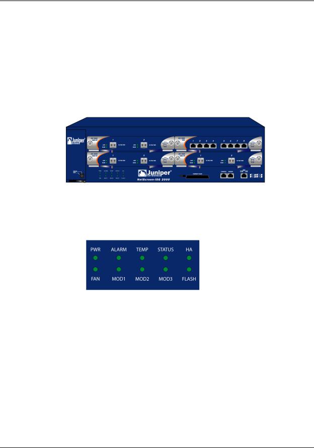
THE FRONT PANEL
The front panel of the NetScreen-ISG 2000 has the following:
•An LED dashboard
•Four removable, replaceable interface modules
•A compact flash card slot
•Management, console, and modem ports
•A fan module
LED Dashboard
The LED dashboard displays up-to-date information about critical NetScreen-ISG 2000 functions.
4 |
User’s Guide |
The Front Panel
The LEDs in the dashboard are as follows:
LED |
Purpose |
Color |
Meaning |
|
|
|
|
POWER |
Power Supply |
green |
Power supply is functioning correctly. |
|
|
|
|
|
|
off |
System is not receiving power. |
|
|
|
|
|
|
red |
There is a problem with the power. |
|
|
|
|
ALARM |
System Alarm |
blinking red |
• Continuous blinking indicates a self-test |
|
|
|
failure during the ScreenOS bootup. May |
|
|
|
also occur due to certain algorithm and ACL |
|
|
|
failures. |
|
|
|
• Blinks once for each software attack. |
|
|
|
|
|
|
amber |
One of the following failures has occurred: |
|
|
|
• Power supply is turned off. |
|
|
|
• Hardware failure. |
|
|
|
• Error with software module. |
|
|
|
|
|
|
off |
No alarm condition present. |
|
|
|
|
TEMP |
Temperature |
green |
Temperature is within safety range. |
|
|
|
|
|
|
orange |
Temperature is outside normal alarm range. |
|
|
|
>132°F or 56°C |
|
|
|
|
|
|
red |
Temperature is outside severe alarm range. |
|
|
|
>150°F or 66°C |
|
|
|
|
STATUS |
System Status |
blinking green |
The system is active. |
|
|
|
|
|
|
amber |
The system is booting. |
|
|
|
|
|
|
off |
The system is off. |
|
|
|
|
HA |
High Availability |
green |
Unit is master. |
|
Status |
|
|
|
amber |
Unit is a backup. |
|
|
|
||
|
|
|
|
|
|
red |
HA has been defined, but unit is not the |
|
|
|
backup system. |
|
|
|
|
|
|
off |
No HA activity defined. |
|
|
|
|
FAN |
Fan Status |
green |
All fans functioning properly. |
|
|
|
|
|
|
red |
One or more fans failed or fan subsystem is |
|
|
|
not receiving power. |
|
|
|
|
MOD1 |
|
green |
Security module is installed. |
|
|
|
|
|
|
off |
No card installed. |
|
|
|
|
MOD2 |
|
green |
Security module is installed. |
|
|
|
|
|
|
off |
No card installed. |
|
|
|
|
NetScreen-ISG 2000 |
5 |

Chapter 1 Overview
LED |
Purpose |
Color |
Meaning |
|
|
|
|
MOD3 |
|
green |
Security module is installed. |
|
|
|
|
|
|
off |
No card installed. |
|
|
|
|
FLASH |
Compact Flash |
green |
PC card is installed in compact flash slot. |
|
Status |
|
|
|
blinking green |
Read-write activity is detected. |
|
|
|
||
|
|
|
|
|
|
off |
Compact flash slot is empty. |
|
|
|
|
Note: To change the Alarm LED from red to green but keep the alarm message(s) in the menu system, use the CLI command clear led alarm.
When you turn on the NetScreen-ISG 2000, the Status LED changes from off to blinking green. Startup takes around 90 seconds to complete. If you want to turn the NetScreenISG 2000 off and on again, wait a few seconds between shutting it down and powering it back up.
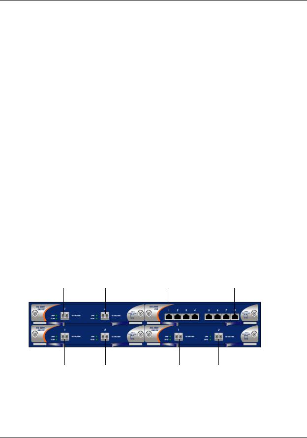
Interface Modules
The front of the NetScreen-ISG 2000 has four interface module bays. Each interface module has two, four, or eight ports, and each port has a pair of LEDs.
Note: You can use both 10/100 and GBIC cards simultaneously for the same NetScreen-ISG 2000; there are no combination restrictions. However, the cards are not hot-swappable.
10/100 Mbps Interface Module
The 10/100 Mbps interface module is appropriate for a 10/100 Base-T LAN. Connect the ports using a twisted pair cable with RJ-45 connectors. (See “Connecting the Device to a Network” on page 24 for cabling guidelines.)
Note: The NetScreen-ISG 2000 supports a maximum port count of 28. If there are 8-port 10/100 modules in each I/O slot, then ports five through eight, in slot 4, are disabled. Under this circumstance, these ports are unavailable for firewall and HA functions.
6 |
User’s Guide |

The Front Panel
TX/RX LED: |
Link LED: |
Dark: Not Active |
Dark: Not Linked |
Orange: Active |
Green: Linked |
Link Activity |
|
|
|
Link Status |
|
|
|
The Mini-GBIC Interface Connector Module
The mini-GBIC interface module provides connectivity to fiber-based, gigabit ethernet LANs. Connect the module using an optical single mode or multi mode cable.
Link LED: |
TX/RX LED: |
|
|
|
|||
Dark: Not Linked |
Dark: Not Active |
||
Green: Linked |
Green: Active |
||
NetScreen-ISG 2000 |
7 |

Chapter 1 Overview
Compact Flash
The compact flash slot is for downloading or uploading system software or configuration files, and for saving log files to a compact flash card.
To download or upload, execute the CLI command save:
save
{ software | config }
from { flash | slot1 filename } to { flash | slot1 filename }
where flash refers to internal flash memory, slot1 refers to the compact flash slot, and filename is the name of the software or configuration file on the card.
For example, the following command downloads the current device configuration to a file named ns2000_config on a card in the compact flash slot:
save config from flash to slot1 ns2000_config
Management Interfaces
The NetScreen-ISG 2000 offers three management interfaces:
Port |
Description |
|
|
Console |
This RJ-45 serial port is for local configuration and administration using the CLI. |
|
Connect the console port to your workstation using an RJ-45 female to DB-9 male |
|
straight-through serial cable. |
|
|
Modem |
This RJ-45 serial port is for connecting to a modem, allowing the user to control the |
|
device remotely. (For security reasons, it is advisable to use a modem only for |
|
troubleshooting or for a one-time configuration, not for regular remote administration.) |
|
|
10/100 MGT |
This management port has a fixed 10/100 Base-T interface and provides a dedicated, |
|
out-of-band connection for management traffic. It has a separate IP address and |
|
netmask, configurable with the CLI or WebUI. (For security reasons, do not pass |
|
session traffic through this interface.) The MGT port is not capable of routing traffic to |
|
other interfaces. This port is only to be used for management purposes. The default IP |
|
address for the MGT port is 192.168.1.1. |
|
|
8 |
User’s Guide |
The Front Panel
High Availability Interfaces
There are no dedicated High Availability (HA) interfaces on the NetScreen-ISG 2000; therefore, you must select and configure the HA ports once the system is running. The HA ports allow you to cable two devices together, and configure them to work as a redundant group. A redundant group consists of a master device and one backup device. If the master device fails, the backup device takes over as the new master, thus avoiding interruption of services. Any number and type of interfaces, from the four interface modules, can be used as an HA port.
Note: It is recommended that you use mini-GBIC interface modules when possible. Do not mix mini-GBIC and 10/100 Mbps ports as HA ports. If you do not have a mini-GBIC interface module, you should use at least two 10/100 Mbps interfaces. For more information on HA configuration, see the NetScreen Concepts & Examples ScreenOS Reference Guide.
For information on cabling for High Availability, see “Connecting the NetScreen-ISG 2000 for High Availability” on page 26.
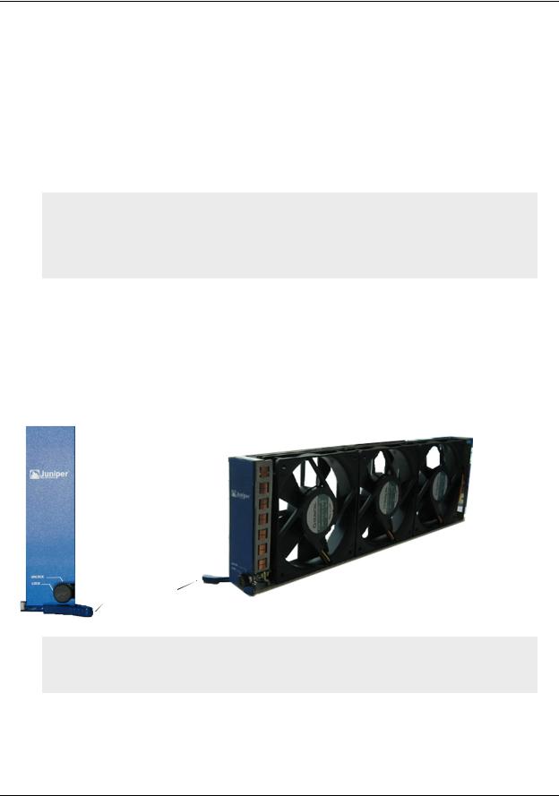
The Fan Module
The NetScreen-ISG 2000 has a three-fan module, which you can access on the left front side of the chassis.
Fan Front |
Fan Module |
Fan Lever
Warning: If a fan stops operating due to failure or removal, the system continues to run. Be sure that the fan tray is not empty for more than two minutes; otherwise, heat failure or permanent damage can occur.
NetScreen-ISG 2000 |
9 |
Chapter 1 Overview
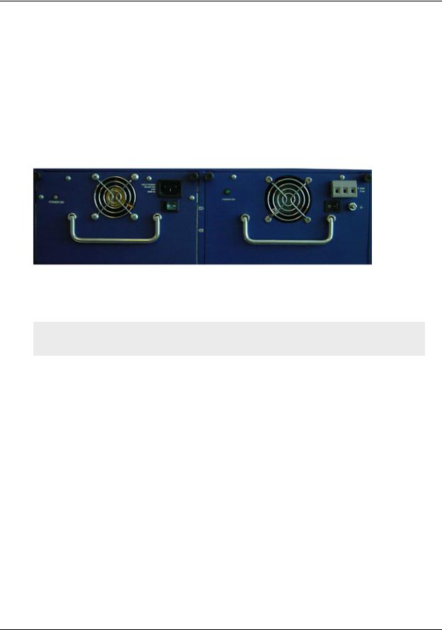
THE REAR PANEL
The rear panel of the NetScreen-ISG 2000 contains the power supplies.
Power Supplies
The NetScreen-ISG 2000 supports two redundant, fault-tolerant and auto-switching power supplies. The power supplies are hot-swappable, so you can remove or replace one power supply without interrupting device operation.
You can order the NetScreen-ISG 2000 with one or two power supplies: DC and AC. Although the NetScreen-ISG 2000 can run with one power supply, it is advisable to install two. This practice minimizes the chance of system failure due to an individual power supply failure.
Important: Do not mix the power supply types because it could seriously damage the device.
When the NetScreen-ISG 2000 contains two power supplies, they share the power load equally. If one power supply fails, the other assumes the full load automatically and the device sends a system alarm. The Power LED only displays two colors: green, indicating that the power supply is functioning correctly and red, which indicates that the power supply has failed.
10 |
User’s Guide |
The Rear Panel
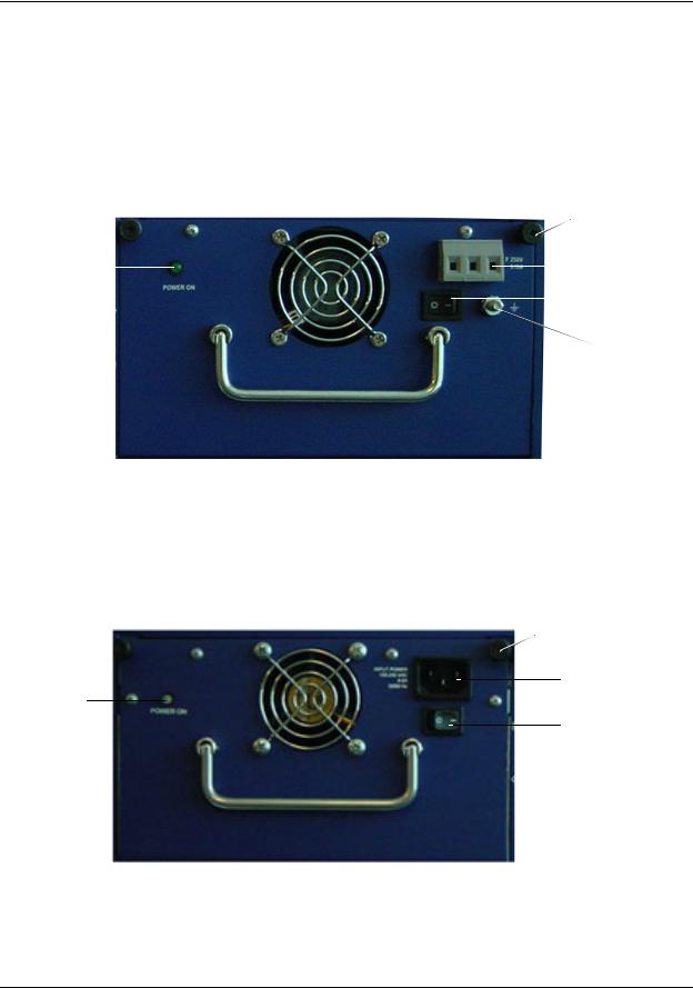
The DC Power Supply
The DC power supply weighs about three pounds. The faceplate contains a power LED, a power switch, a cooling fan vent, and three DC power terminal blocks that connect to power cables.
The following figure shows the NetScreen-ISG 2000 DC power supply.
|
|
|
|
Thumbscrew |
||
|
|
|
|
|
|
Terminal |
Power LED |
|
|
|
|
|
Blocks |
|
|
|
||||
|
|
|
|
|||
|
|
|
|
|
|
Power |
|
|
|
|
|
|
Switch |
|
|
|
|
Hex Nut |
||
The AC Power Supply
The AC power supply weighs about three pounds. The faceplate contains a power LED, a power switch, a cooling fan vent, and a male power outlet.
The figure below shows the NetScreen-ISG 2000 AC power supply.
Thumbscrew
Power
Outlet
Power LED
Power
Switch
NetScreen-ISG 2000 |
11 |

Chapter 1 Overview
12 |
User’s Guide |

2
Installing the Device
This chapter describes how to install a NetScreen-ISG 2000 in an equipment rack. Topics in this chapter include:
•“General Installation Guidelines” on page 14
•“Equipment Rack Mounting” on page 14
–“Equipment Rack Installation Guidelines” on page 14
–“Equipment Rack Accessories and Required Tools” on page 15
–“Mid-Mount” on page 16
–“Rear-and-Front Mount” on page 17
•“Installing and Connecting the AC Power Supply” on page 18
•“Installing and Wiring a DC Power Supply” on page 18
Note: For safety warnings and instructions, please refer to the NetScreen Safety Guide. The instructions in this guide warn you about situations that could cause bodily injury. Before working on any equipment, be aware of the hazards involved with electrical circuitry and be familiar with standard practices for preventing accidents.
NetScreen-ISG 2000 |
13 |

Chapter 2 Installing the Device
GENERAL INSTALLATION GUIDELINES
Observing the following precautions can prevent injuries, equipment failures, and shutdowns.
•Never assume that the power supply is disconnected from a power source. Always check first.
•Room temperature might not be sufficient to keep equipment at acceptable temperatures without an additional circulation system. Ensure that the room in which you operate the device has adequate air circulation.
•Do not work alone if potentially hazardous conditions exist.
•Look carefully for possible hazards in your work area, such as moist floors, ungrounded power extension cables, frayed power cords, and missing safety grounds.
Important: Although you can place the device on a desktop for operation, it is not advisable to deploy a NetScreen-ISG 2000 in this manner. The best deployment technique is equipment rack mounting, described below.
Warning: To prevent abuse and intrusion by unauthorized personnel, install the NetScreen-ISG 2000 in a locked-room environment.
EQUIPMENT RACK MOUNTING
The NetScreen-ISG 2000 comes with accessories for mounting the device in a standard 19-inch equipment rack.
Equipment Rack Installation Guidelines
The location of the chassis, the layout of the equipment rack, and the security of your wiring room are crucial for proper system operation.
Use the following guidelines while configuring your equipment rack.
•Enclosed racks must have adequate ventilation. Such ventilation requires louvered sides and a fan to provide cooling air.
•When mounting a chassis in an open rack, be sure that the rack frame does not block the intake or exhaust ports. If you install the chassis on slides, check the position of the chassis when it is seated all the way into the rack.
•In an enclosed rack with a ventilation fan in the top, equipment higher in the rack can draw heat from the lower devices. Always provide adequate ventilation for equipment at the bottom of the rack.
•Baffles can isolate exhaust air from intake air. The best placement of the baffles depends on the airflow patterns in the rack.
14 |
User’s Guide |
Equipment Rack Mounting
Equipment Rack Accessories and Required Tools
Rack mounting requires the following accessories and tools:
•1 Phillips-head screwdriver (not provided)
•4 screws to match the rack (if the thread size of the screws provided in the NetScreen-ISG 2000 product package do not fit the thread size of the rack)
•The included rear slide mount kit (for the rear-and-front-mount method)
Rear Slide Mount Kit
Slides (2)
Rear mount brackets (2)
10-32 x ½” Screws (8)
M4 Screws (6)
There are two ways to rack mount the NetScreen-ISG 2000:
•Mid-mount
•Rear-and-front mount
Note: NetScreen strongly recommends the rear-and-front rack mount configuration.
NetScreen-ISG 2000 |
15 |
Chapter 2 Installing the Device
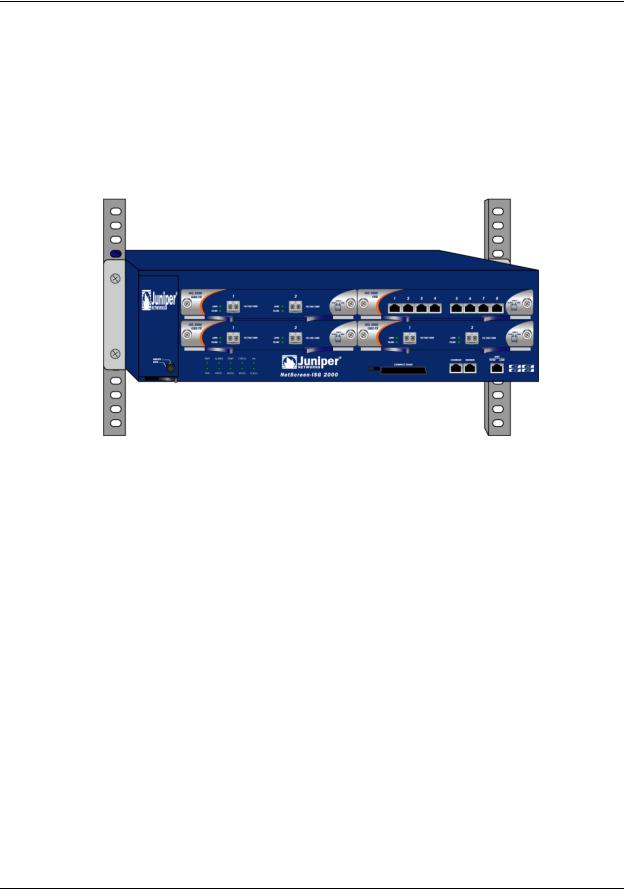
Mid-Mount
To mid-mount the NetScreen-ISG 2000:
1.Screw the left and right plates to the middle of each side of the NetScreen-ISG 2000 chassis.
2.Slide the NetScreen-ISG 2000 in the rack.
3.Screw the left and right plates to the rack.
16 |
User’s Guide |
Equipment Rack Mounting
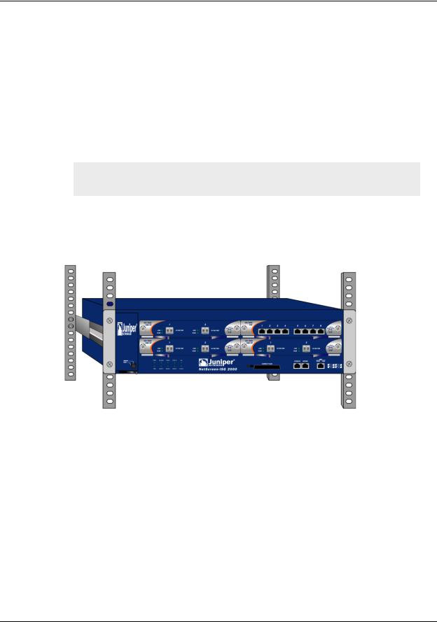
Rear-and-Front Mount
To mount the NetScreen-ISG 2000 with support from the rear and front, use the rear slide mount kit.
1.Screw the left and right plates to the front of each side of the NetScreen-ISG 2000 chassis.
2.Screw the rear mount bracket to the rear rack posts.
3.With the indented groove that runs the length of each slide facing outward, screw the slides to the middle of each side of the NetScreen-ISG 2000 chassis.
Note: Depending on the depth of your equipment rack, you can attach the slides along the length of the sides or extend them over the rear of the chassis.
4.Slip the slides into the rear mount brackets.
5.Push the NetScreen-ISG 2000 forward until the left and right plates contact the front rack posts.
6.Screw the left and right plates to the rack.
NetScreen-ISG 2000 |
17 |

Chapter 2 Installing the Device
INSTALLING AND CONNECTING THE AC POWER SUPPLY
To install and connect the AC power supply to the NetScreen-ISG 2000:
1.Slide the power supply into one of the power compartments in the back of the system.
2.Fasten the power supply to the system by tightening the corner screws into the eyelets on the sides of the power supply. (If you want to install two power supplies, repeat steps 1 and 2 for the other power supply.)
3.Connect the female end of a standard power cord to the male connector on the back of each power supply.
4.Connect each power cord to a standard 100-240-volt power outlet.
Note: Whenever you deploy two power supplies to a NetScreen-ISG 2000, connect each to a different power source. Each power supply is intended to receive power from separate feeds.
5.Turn on the power switch.
Note: If there are multiple power supplies in the NetScreen-ISG 2000 and any of them are off, the Alarm LED on the management module glows red. This warning indicates that maximum system reliability requires all installed power supplies to be operational.
INSTALLING AND WIRING A DC POWER SUPPLY
To install and connect the DC power supply to the NetScreen-ISG 2000:
1.Slide the power supply into one of the power compartments in the back of the system.
2.Fasten the power supply to the system by tightening the corner screws into the eyelets on the sides of the power supply.
3.If you want to install two power supplies, repeat steps 1 and 2 for the remaining power supply.
4.Turn on the power switch.
The DC power supply, ON/OFF switch, grounding screw, and terminal blocks are located on the faceplate of the power supply unit.
Warning: You must shut off current to the DC feed wires before connecting the wires to the power supplies. Also, make sure that the ON/OFF switch is in the off position.
To connect the DC power supply to a grounding point at your site:
1.Remove the hex nut on the grounding screw.
2.Place the ground lug on the screw and tighten the hex nut securely.
18 |
User’s Guide |

Installing and Wiring a DC Power Supply
3.Connect the other end of the grounding lug wire to a grounding point at your site.
To connect DC power feeds to the terminal blocks:
1.Loosen the retaining screws on each terminal block.
2.Insert the 0V DC (positive voltage) return wire into the center COM connector and the -48V DC power feed wire into either the left or right connector.
3.Fasten the screws over the connectors.
4.Turn on the power switch.
Note: If there are multiple power supplies in the NetScreen-ISG 2000 and any of them are off, the Alarm LED on the management module glows red. This warning indicates that maximum system reliability requires all installed power supplies to be operational.
NetScreen-ISG 2000 |
19 |

Chapter 2 Installing the Device
20 |
User’s Guide |

3
Configuring the Device
This chapter describes how to connect a NetScreen-ISG 2000 to your network and perform initial configuration on the device. Topics in this chapter include:
•“Operational Modes” on page 22
–“Transparent Mode” on page 22
–“Route Mode” on page 22
•“The NetScreen-ISG 2000 Interfaces” on page 23
–“Configurable Interfaces” on page 23
–“The Ethernet Interfaces” on page 23
–“Interfaces to Change During Initial Configuration” on page 24
•“Connecting the Device to a Network” on page 24
–“Connecting the NetScreen-ISG 2000 as a Single Security System” on page 25
–“Connecting the NetScreen-ISG 2000 for High Availability” on page 26
•“Performing Initial Connection and Configuration” on page 29
–“Establishing a Terminal Emulator Connection” on page 29
–“Changing Your Admin Name and Password” on page 30
–“Setting Port and Interface IP Addresses” on page 31
•“Configuring the Device for Telnet and WebUI Sessions” on page 33
–“Starting a Console Session Using Telnet” on page 33
–“Starting a Console Session Using Dialup” on page 34
–“Establishing a WebUI Management Session” on page 34
–“Configuring the Chassis Alarm” on page 35
•“Using CLI Commands to Reset the Device” on page 35
Note: You must register your product at www.netscreen.com/cso so that certain ScreenOS services, such as Deep Inspection Signature Service, can be activated on the device. After registering your product, use the WebUI or CLI to obtain the subscription for the service. For more information about registering your product and obtaining subscriptions for specific services, see Volume 2 in the NetScreen Concepts & Examples ScreenOS Reference Guide.
NetScreen-ISG 2000 |
21 |

Chapter 3 Configuring the Device
OPERATIONAL MODES
The NetScreen-ISG 2000 supports two device modes: Transparent mode and Route mode. The default mode is Route.
Note: Because you enable NAT capability by configuring interfaces and creating security policies, NAT is not considered a device mode. To configure your device for NAT, the device must be in Route mode.
Transparent Mode
In Transparent mode, the NetScreen-ISG 2000 operates as a Layer-2 bridge. Because the device cannot translate packet IP addresses, it cannot perform Network Address Translation (NAT). Consequently, any IP address in your trusted (local) networks must be public, routable, and accessible from untrusted (external) networks.
In Transparent mode the NetScreen device is invisible to the network. However, the device can still perform firewall, VPN, and traffic management according to configured security policies.
Route Mode
In Route mode, the NetScreen-ISG 2000 operates at Layer 3. Because you can configure each interface using an IP address and subnet mask, you can configure individual interfaces to perform NAT.
•When the interface performs NAT services, the device translates the source IP address of each outgoing packet into the IP address of the untrusted port. It also replaces the source port number with a randomly-generated value. You can also perform translations using either Mapped IP (MIP) or Virtual IP (VIP) addresses.
•When the interface does not perform NAT services, the source IP address and port number in each packet header remain unchanged. Therefore, your local hosts must have public IP addresses.
For more information on NAT, see the NetScreen Concepts and Examples ScreenOS Reference Guide.
22 |
User’s Guide |
The NetScreen-ISG 2000 Interfaces
THE NETSCREEN-ISG 2000 INTERFACES
The NetScreen-ISG 2000 provides physical ports, each of which can serve as a physical interface. In addition, you can configure Ethernet ports to serve as virtual (logical) interfaces.
Configurable Interfaces
The interfaces available on the NetScreen-ISG 2000 are as follows:
Interface Type |
Description |
|
|
Ethernet interfaces |
ethernetn1/n2 specifies a physical Ethernet interface, denoted by an |
|
interface module in a slot (n1) and a physical port (n2) on the module. |
|
|
|
ethernetn1/n2.n3 specifies a logical interface, denoted by an interface |
|
module in a slot (n1), a physical port (n2) on the module, and a logical |
|
interface number ( .n3). You create logical interfaces using the set interface |
|
command. |
|
|
Layer-2 interfaces |
vlan1 specifies the interface used for VPNs while the NetScreen device is in |
|
Transparent mode. |
|
|
Tunnel interfaces |
tunnel.n specifies a tunnel interface. Use this interface for VPN traffic. |
|
|
Function interfaces |
mgt specifies an interface bound to the MGT zone. The default IP address of |
|
this interface is 192.168.1.1. |
|
|
The Ethernet Interfaces
The ethernet interfaces are located on the interface modules (see “Interface Modules” on page 6). The interface names are as follows:
ethernet1/1 ethernet1/2 |
ethernet3/1 . . . . . . |
ethernet3/8 |
ethernet2/1 ethernet2/2 |
ethernet4/1 ethernet4/2 |
NetScreen-ISG 2000 |
23 |

Chapter 3 Configuring the Device
Interfaces to Change During Initial Configuration
The default IP address and subnet mask settings for NetScreen-ISG 2000 interfaces are 0.0.0.0 and 0.0.0.0, respectively. The exception is MGT, a special interface used only for device management. The default IP address and subnet mask settings for the MGT interface are 192.168.1.1 and 255.255.255.0, respectively.
•For all operational modes, it is advisable to change the IP address and subnet mask for the MGT interface, and to use it exclusively for out of band management.
•To access the vlan1 interface in Transparent mode, you must change the IP address and subnet mask of vlan1 to match your current network.
•In Transparent mode, only the MGT and vlan1 interfaces may have a new IP address and subnet mask. All others must keep their default IP address and subnet mask settings (0.0.0.0 and 0.0.0.0, respectively).
•In Route mode (with or without NAT), at least two Ethernet interfaces must have new IP addresses and subnet masks.
Note: For more information on setting IP addresses, see “Setting Port and Interface IP Addresses” on page 31
CONNECTING THE DEVICE TO A NETWORK
The NetScreen-ISG 2000 has four interface module bays, which can contain the following types of modules:
•10/100 Mbps interface module, for 10/100 Base-T connections (4 and 8 ports)
•Mini-GBIC interface module, for fiber-optic connections (2 ports)
The type of network used by your organization determines the kind of interface needed to connect the NetScreen-ISG 2000. (For more information on interface modules, see “Interface Modules” on page 6.)
Note: Because of the wide variety of available routers, hubs, and switches, the cabling configuration presented here might not satisfy your network connection requirements. If the cabling suggested in this chapter does not work, try other cable configurations until a link light indicates an active link.
24 |
User’s Guide |
Loading...