

Page 1
EFG 213-320
09.09 -
Operating instructions G
51151902
09.11
EFG 213
EFG 215
EFG 216k
EFG 216
EFG 218k
EFG 218
EFG 220
EFG 316k
EFG 316
EFG 318k
EFG 318
EFG 320
Page 2

Declaration of Conformity
Jungheinrich AG, Am Stadtrand 35, D-22047 Hamburg
Manufacturer or agent acting in the European Union
Type Option Serial no. Year of
EFG 213
EFG 215
EFG 216k
EFG 216
EFG 218k
EFG 218
EFG 220
EFG 316k
EFG 316
EFG 318k
EFG 318
EFG 320
Additional information
On behalf of
Date
G EU Conformity Declaration
The undersigned hereby declare that the powered industrial truck described below in
detail complies with the European Directives 2006/42/EC (Machinery Directive) and
2004/108/EEC (Electromagnetic Compatibility - EMC) including amendments as well
as the legislative decree to incorporate the directives in national law. The signatories
are in each case individually authorized to compile the technical documents.
manufacture
09.11 EN
3
Page 3

09.11 EN
4
Page 4

EN
WARNING!
Unsuitable batteries that have not been approved by Jungheinrich for the truck
can be hazardous
The design, weight and dimensions of the battery have a considerable effect on the
operational safety of the truck, in particular its stability and capacity. The use of
unsuitable batteries that have not been approved by Jungheinrich for the truck can
lead to a deterioration of the braking system during energy recovery operations and
also cause considerable damage to the electrical control system. The use of batteries
that have not been approved by Jungheinrich can therefore affect the health and
safety of personnel.
XOnly manufacturer-approved batteries may be used on the truck.
XReplacement of the battery equipment requires the manufacturer's agreement.
XWhen replacing/installing the battery make sure the battery is securely located in
the battery compartment of the truck.
XDo not use batteries that have not been approved by the manufacturer.
Page 5

Page 6

Foreword
Notes on the operating instructions
The present ORIGINAL OPERATING INSTRUCTIONS are designed to provide
sufficient instruction for the safe operation of the industrial truck. The information is
provided clearly and concisely. The chapters are arranged by letter and the pages are
numbered continuously.
The operator manual details different industrial truck models. When operating and
servicing the industrial truck, make sure that the particular section applies to your
truck model.
Our trucks are subject to ongoing development. Jungheinrich reserves the right to
alter the design, equipment and technical features of the system. No guarantee of
particular features of the truck should therefore be assumed from the present
operating instructions.
Safety notices and text mark-ups
Safety instructions and important explanations are indicated by the following
graphics:
DANGER!
Indicates an extremely hazardous situation. Failure to comply with this instruction will
result in severe irreparable injury and even death.
WARNING!
Indicates an extremely hazardous situation. Failure to comply with this instruction
may result in severe irreparable injury and even death.
CAUTION!
Indicates a hazardous situation. Failure to comply with this instruction may result in
slight to medium injury.
NOTE
Indicates a material hazard. Failure to comply with this instruction may result in
material damage.
Z Used before notices and explanations.
t Indicates standard equipment
o Indicates optional equipment
Copyright
Copyright of these operating instructions remains with JUNGHEINRICH AG.
09.11 EN
5
Page 7

Jungheinrich Aktiengesellschaft
Am Stadtrand 35
22047 Hamburg - Germany
Tel: +49 (0) 40/6948-0
www.jungheinrich.com
09.11 EN
6
Page 8

Table of Contents
A Correct Use and Application ................................................... 11
1General....................................................................................................11
2Correct application...................................................................................11
3Approved application conditions..............................................................12
4Proprietor responsibilities........................................................................13
5Adding attachments and/or accessories..................................................13
BTruck Description....................................................................15
1Application...............................................................................................15
1.1 Truck models and rated capacity............................................................. 15
2Assemblies and Functional Description...................................................16
2.1 Assembly Overview ................................................................................. 16
2.2 Functional Description ............................................................................. 17
3Technical Specifications..........................................................................18
3.1 Performance data .................................................................................... 19
3.2 Dimensions.............................................................................................. 21
3.3 Weights.................................................................................................... 27
3.4 Mast versions .......................................................................................... 28
3.5 Tyre type.................................................................................................. 29
3.6 Engine Data............................................................................................. 30
3.7 EN norms................................................................................................. 31
3.8 Conditions of use..................................................................................... 32
3.9 Electrical requirements ............................................................................ 32
4 Identification points and data plates ........................................................ 33
4.1 Indication Points ...................................................................................... 33
4.2 Data plate ................................................................................................ 35
4.3 Truck capacity plate................................................................................. 36
4.4 Attachment capacity plate ....................................................................... 37
5Stability....................................................................................................37
CTransport and Commissioning................................................39
1Transport.................................................................................................39
2Truck laden..............................................................................................39
2.1 Centre of gravity of the truck ................................................................... 39
2.2 Lifting the truck by crane ......................................................................... 40
2.3 Loading with another industrial truck ....................................................... 41
3 Securing the truck during transport ......................................................... 42
4Using the Truck for the First Time...........................................................44
09.11 EN
7
Page 9

DBattery - Servicing, Recharging, Replacement.......................45
1 Safety Regulations Governing the Handling of Lead-Acid Batteries ....... 45
1.1 General notes on handling batteries........................................................ 47
2Battery types............................................................................................48
2.1 Battery dimensions .................................................................................. 49
3 Exposing the battery................................................................................ 50
4 Charging the battery ................................................................................ 51
4.1 Charging the battery with a stationary charger........................................ 51
4.2 Charging the battery with an on-board charger ....................................... 52
5Battery removal and installation..............................................................56
5.1 Battery holder assembly .......................................................................... 57
5.2 Removal and installation using an EJE pallet truck with Snapfit battery
holder (o) ................................................................................................. 59
5.3 Removal and installation using a hand pallet truck with Snapfit battery
holder (o) ................................................................................................. 62
5.4 Removal and installation using a multi-adapter (o) ................................. 65
5.5 Removal and installation using a worktable for crane loading (o) ........... 67
5.6 Removal and installation using a fork shoe (o)........................................ 69
5.7 Removal and installation using a roller conveyor (o)............................... 71
5.8 Hook-on battery door removal and installation (o)................................... 72
EOperation................................................................................73
1 Safety Regulations for the Operation of the Forklift Truck....................... 73
2Displays and Controls..............................................................................75
2.1 Control panel with display unit................................................................. 79
2.2 Armrest control panel switch (o) .............................................................. 82
2.3 Side compartment control panel switch (o) ............................................. 83
2.4 Display..................................................................................................... 84
3 Preparing the Truck for Operation ........................................................... 87
3.1 Checks and operations to be performed before starting daily operation . 87
3.2 Entry and exit........................................................................................... 89
3.3 Trucks with reduced headroom X (o) ...................................................... 89
3.4 Setting up the operator position............................................................... 90
3.5 Seat Belt .................................................................................................. 94
4 Industrial Truck Operation ....................................................................... 95
4.1 Safety regulations for truck operation...................................................... 95
4.2 Preparing the truck for operation ............................................................. 97
4.3 Setting the time........................................................................................ 98
4.4 Parking the truck securely ....................................................................... 99
4.5 Emergency Disconnect............................................................................ 100
4.6 Travel....................................................................................................... 101
4.7 Steering ................................................................................................... 102
4.8 Brakes ..................................................................................................... 103
4.9 Adjusting the forks ................................................................................... 105
4.10 Replacing the forks .................................................................................. 106
4.11 Lifting, transporting and depositing loads ................................................ 107
4.12 Operating the lift mechanism and integrated attachments ...................... 109
4.13 Safety instructions for operating additional attachments ......................... 116
4.14 Operating additional attachments for the SOLO-PILOT .......................... 120
8
09.11 EN
Page 10

4.15 Operating additional attachments for the Multi Pilot ................................ 122
4.16 Fitting additional attachments .................................................................. 124
5Towing trailers.........................................................................................126
6Optional equipment.................................................................................128
6.1 CanCode keypad..................................................................................... 128
6.2 Assistance systems ................................................................................. 132
6.3 Steel cab.................................................................................................. 134
6.4 Sliding windows ....................................................................................... 134
6.5 Automatic / mechanical folding gate........................................................ 135
6.6 Panel door ............................................................................................... 136
6.7 Operator position extension..................................................................... 136
6.8 Adjusting the driver’s seat ....................................................................... 137
6.9 Heating .................................................................................................... 138
6.10 Removable load backrest ........................................................................ 139
6.11 Lift cutout override ................................................................................... 139
6.12 Fire extinguisher ...................................................................................... 140
6.13 Tilt angle display ...................................................................................... 140
6.14 Rockinger coupling with hand lever or remote control............................. 141
6.15 Camera system ....................................................................................... 142
6.16 Control layout “N” .................................................................................... 143
7Troubleshooting.......................................................................................144
7.1 Troubleshooting....................................................................................... 144
7.2 Operating the truck without its own drive system .................................... 146
7.3 Emergency lowering ................................................................................ 149
FIndustrial Truck Maintenance..................................................151
1 Operational Safety and Environmental Protection................................... 151
2Maintenance Safety Regulations.............................................................152
3Servicing and Inspection.........................................................................157
4Maintenance checklist EFG 213-220.......................................................158
4.1 Owner ...................................................................................................... 158
4.2 Customer Service .................................................................................... 161
5Maintenance checklist EFG 316-320.......................................................170
5.1 Owner ...................................................................................................... 170
5.2 Customer Service .................................................................................... 173
6 Lubricants and Lubrication Schedule ...................................................... 182
6.1 Handling consumables safely.................................................................. 182
6.2 Lubrication Schedule ............................................................................... 184
6.3 Consumables........................................................................................... 185
7Maintenance and repairs.........................................................................187
7.1 Preparing the truck for maintenance and repairs .................................... 187
7.2 Opening the rear panel............................................................................ 187
7.3 Checking the wheel attachments............................................................. 188
7.4 Hydraulic system ..................................................................................... 189
7.5 Check the gear oil level ........................................................................... 192
7.6 Heating .................................................................................................... 193
7.7 Adding window washer system fluid........................................................ 193
7.8 Checking electrical fuses......................................................................... 194
7.9 Seat belt maintenance............................................................................. 198
7.10 Restoring the truck to service after maintenance and repairs ................. 199
8Decommissioning the industrial truck......................................................200
09.11 EN
9
Page 11

8.1 Prior to decommissioning ........................................................................ 201
8.2 During decommissioning ......................................................................... 201
8.3 Restoring the truck to service after decommissioning ............................. 202
9Safety tests to be performed at intervals and after unusual incidents.....203
10 Final de-commissioning, disposal............................................................ 204
11 Human vibration measurement ............................................................... 204
10
09.11 EN
Page 12

Appendix
JH Traction Battery Operating Instructions
These operating instructions apply only to Jungheinrich battery models. If using
Z
another brand, refer to the manufacturer's operating instructions.
If using a battery with closed EPzV and EPzV ironclad plates, this must first be
M
discussed with the manufacturer.
0506.GB
1
Page 13

0506.GB
2
Page 14

ACorrect Use and Application
1General
The industrial truck described in the present operating instructions is designed for
lifting, lowering and transporting load units.
It must be used, operated and serviced in accordance with the present instructions.
Any other type of use is beyond the scope of application and can result in damage to
personnel, the industrial truck or property.
2 Correct application
NOTE
The maximum load and load distance are indicated on the load chart and must not be
exceeded.
The load must rest on the load handler or be lifted by an attachment approved by the
manufacturer.
The load must rest on the back of the fork carriage and centrally between the forks.
–Lifting and lowering loads.
–Transporting lowered loads over short distances.
–Do not travel with a raised load (>30 cm).
– Do not carry or lift passengers.
–Do push or pull load units.
– Occasional towing of trailer loads.
–When towing trailer loads the load must be secured on the trailer.
– The permissible trailer load must not be exceeded.
09.11 EN
11
Page 15

3Approved application conditions
DANGER!
Do not exceed the permissible surface and spot load limits on the travel routes.
At blind spots get a second person to assist.
The driver must ensure that the loading dock / ramp cannot move or come loose
during loading / unloading.
–Operation in industrial and commercial environments.
–Permissible temperature range -20°C to 40°C.
–Operation only on secure, level surfaces with sufficient capacity.
–Operation only on routes that are visible and approved by the proprietor.
–Negotiating inclines up to a maximum of 15 %.
–Do not negotiate inclines crosswise or at an angle. Transporting loads downhill.
–Operation in partially public traffic.
WARNING!
Extreme conditions
XSpecial equipment and authorisation are required if the truck is to be constantly
used in extreme conditions, especially in dusty or corrosive atmospheres.
XThe truck is not authorised for use in areas at risk of explosion.
XIn adverse weather conditions (thunder, lightning) the industrial truck must not be
operated outside or in endangered areas.
12
09.11 EN
Page 16

4Proprietor responsibilities
For the purposes of the present operating instructions the “proprietor” is defined as
any natural or legal person who either uses the industrial truck himself, or on whose
behalf it is used. In special cases (e.g. leasing or renting) the proprietor is considered
the person who, in accordance with existing contractual agreements between the
owner and user of the industrial truck, is charged with operational duties.
The proprietor must ensure that the industrial truck is used only for the purpose for
which it is intended and that there is no danger to life and limb of the user and third
parties. Furthermore, accident prevention regulations, safety regulations and
operating, servicing and repair guidelines must be followed. The proprietor must
ensure that all users have read and understood these operating instructions.
NOTE
Failure to comply with the operating instructions shall invalidate the warranty. The
same applies if improper work is carried out on the truck by the customer or third
parties without the permission of the manufacturer.
5 Adding attachments and/or accessories
Adding accessories
The mounting or installation of additional equipment which affects or enhances the
performance of the forklift truck requires the written permission of the manufacturer.
Local authority approval may also need to be obtained.
Local authority approval does not however constitute the manufacturer’s approval.
09.11 EN
13
Page 17

14
09.11 EN
Page 18
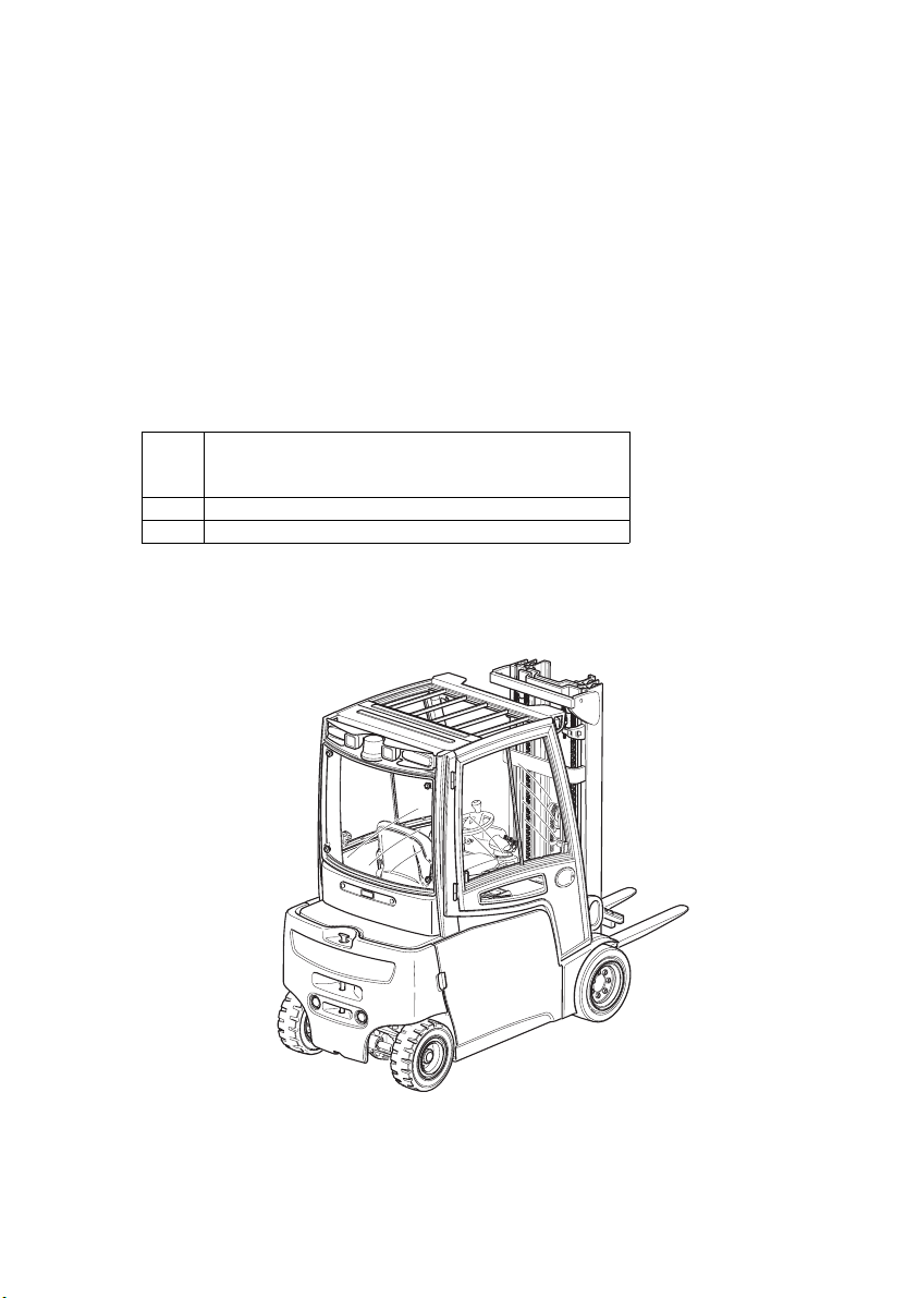
B Truck Description
1 Application
The EFG 213-320 is a three- or four-wheel electric sit-down counterbalanced truck. It
is a cantilever counterbalanced truck which can lift, transport and deposit loads using
the load handler attached in front.
Closed bottom pallets can also be lifted.
1.1 Truck models and rated capacity
The rated capacity depends on the model. The rated capacity can be derived from
the model description.
EFG 213-220213
EFG
213-
Model name
220
2Series
13 Rated capacity x 100 kg
The rated capacity does not generally match the permissible capacity. The capacity
can be found on the load chart attached to the rack.
09.11 EN
15
Page 19
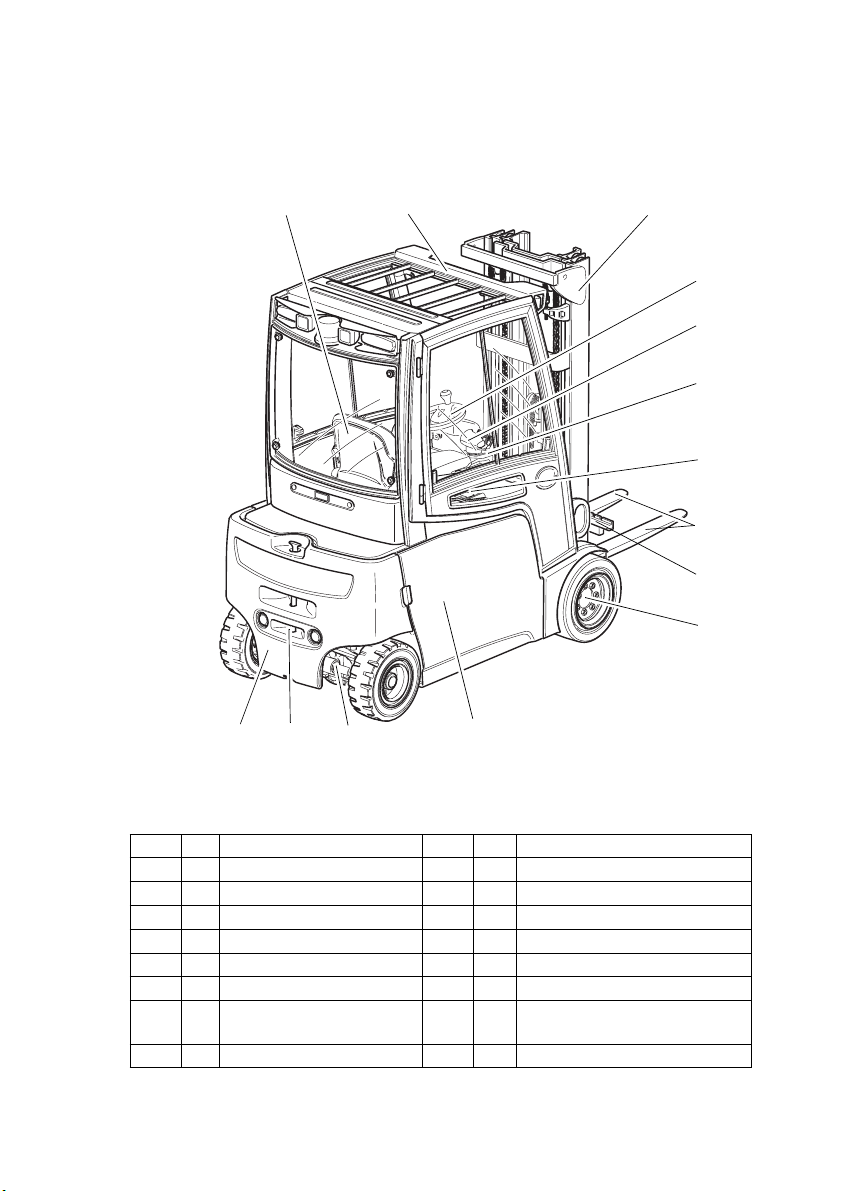
2Assemblies and Functional Description
2.1 Assembly Overview
12
12
13
14
3
4
5
6
7
8
9
10
11
Item Description Item Description
1 t Driver's seat 8 t Fork tines
2 t Overhead guard 9 t Fork carriage
3 t Mast 10 t Power
4 t Steeri ng w heel 11 t Battery door
5 t Lift mechanism control 12 t Steer ax le
6 t Control / display unit 13 t Trailer coupling
7 t Emergency Disconnect
switch
t Standard equipment o Optional equipment
16
14 t Counterweight
09.11 EN
Page 20

2.2 Functional Description
Chassis
The chassis, in conjunction with the counterweight, forms the supporting base
structure of the truck. It is used to support the main components.
Operator position and overhead guard
The overhead guard (2) comes in a range of models and protects the driver from
falling objects and other external
influences. All the controls are ergonomically arranged. The steering column and
driver's seat can be adjusted individually.
The controls and warnings on the control and display unit (6) enable the system to be
monitored during operation, thereby ensuring a very high level of safety.
Steering system
The electric steering offers a high level of efficiency and ergonomics. The height and
tilt angle of the steering column are adjustable and can be set to suit all drivers. The
low cross-section means the driver has maximum legroom at all times.
The steering is particularly smooth, offering a high level of efficiency. This significantly
reduces the
overall energy consumption.
The steer angle is shown in the display.
Wheels
There is a choice of super elastic or fully rubber tyres as well as optional pneumatic
tyres.
Drive system and brakes
The 2-motor front drive provides maximum traction to the drive wheels at all times.
When cornering, the exact speed required for the wheel on the inside or outside of
the bend respectively is set in proportion to the steer angle.
The service brake is a maintenance-free disk brake. The truck also brakes
regeneratively via the drive motors. The energy recovered in the process is fed back
to the battery.
The parking brake automatically applies
as soon as the truck comes to a halt. A warning indicator appears when the parking
brake is applied. Brake system
faults are shown on the control and display unit (6).
09.11 EN
17
Page 21

Emergency Stop safety feature
If the system recognises a fault in the steering, an emergency stop
is automatically introduced. The truck brakes to a halt, the travel direction does not
change.
An event message is shown in the control and display unit. The truck performs a selftest
whenever it is switched on. Travel is only enabled again
when the truck is operational and the parking brake (= emergency stop) released.
Hydraulic system
A multi-pilot valve allows for sensitive operation of the functions via the controls. A
speed-controlled hydraulic pump ensures a proportionate and efficient supply to the
hydraulic functions.
Mast
Two or three-stage masts, optionally with free lift function; narrow mast sections
ensure excellent visibility of the forks and attachments. Fork carriage and mast run
on permanently lubricated and hence maintenance-free support rollers.
Attachments
The trucks can be optionally fitted with mechanical and hydraulic attachments.
3Technical Specifications
All technical details refer to standard trucks.
Values indicated with *) may vary, depending on the
types of equipment used (e.g. mast, cabin, tyres etc.).
Z Technical data specified in accordance with VDI 2198.
Technical modifications and additions reserved.
18
09.11 EN
Page 22

3.1 Performance data
EFG 213-220
Description EFG
213 215
QRated capacity
(where
C=500mm)
1
1300 1500 1600 1800 2000 kg
)
C Load centre 500 500 500 500 500 mm
Travel speed
Lift speed
with / without load
Lowering speed
with / without load
16/16 16/16 16/16 16/16 16/16
0.48/0.60 0.46/0.60 0.49/0.60 0.44/0.55 0.40/0.55 m/s
0.55/0.55 0.55/0.55 0.55/0.55 0.55/0.55 0.55/0.55 m/s
Gradeability
(30 min)
7.6/12.5 7.3/12.3
with / without load
Max. gradeability
2
) (5 min)
28.0/35.0 27.0/35.0 27.0/35.0
with / without load
Acceleration
(10 m)
3.6/3.2 3.8/3.4 3.8/3.4 3.9/3.5 4.0/3.5 s
with / without load
Max. operating
pressure
Oil flow for
attachments
1)
for vertical mast.
2)
The values shown represent the maximum gradeability to overcome short
200 200 200 200 200 bar
25 25 25 25 25
differences in height and surface unevenness (surface edges). The truck must not
operate on inclines of more than 15%.
216k 218k
216 218
7.3/12.3 6.2/10.7
7.0/11.5 5.9/10.5
26.0/35.0
25.0/35.0
220
km/
h
5.7/10.4 %
24.0/35.0 %
l/
min
09.11 EN
19
Page 23

EFG 316-320
Description EFG
316k 316 318k 318 320
QRated
capacity (where
1600 1600 1800 1800 2000 kg
C = 500 mm)1)
C Load centre 500 500 500 500 500 mm
Travel Speed *
Lift speed
w / w.o. load
Lowering speed
w / w.o. load
17/17 17/17 17/17 17/17 17/17
0.49/0.60 0.49/0.60 0.44/0.55 0.44/0.55 0.40/0.55 m/s
0.55/0.55 0.55/0.55 0.55/0.55 0.55/0.55 0.55/0.55 m/s
km/
h
Gradeability
(30 min)
7.3/12.3 7.0/11.5 6.2/10.7 5.9/10.5 5.7/10.4 %
w./w.o. load
Max. gradeability
2)
(5 min)
27.0/35.0 27.0/35.0 26.0/35.0 25.0/35.0 24.0/35.0 %
w./w.o. load
Acceleration
(10 m)
3.8/3.4 3.8/3.4 3.9/3.5 3.9/3.5 4.0/3.5 s
w./w.o. load
Max. operating
pressure
Oil flow for
attachments
1)
for vertical mast.
2)
The values shown represent the maximum gradeability to overcome short
200 200 200 200 200 bar
25 25 25 25 25
l/
min
differences in height and surface unevenness (surface edges). The truck must not
operate on inclines of more than 15%.
20
09.11 EN
Page 24

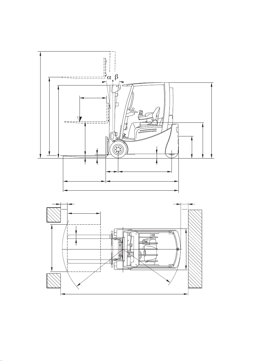
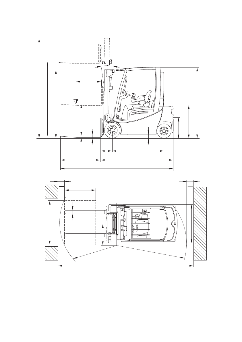
3.2 Dimensions
EFG 213-220
Description EFG
213 215
a/2 Safety distance 100 100 100 100 100 mm
Mast height
h
1
retracted
2000 2000 2000 2000 2000 mm
h2Free lift 150 150 150 150 150 mm
h3Lift 3000 3000 3000 3000 3000 mm
h4Mast height
extended
h6Overhead guard
height
3560 3560 3560 3587 3587 mm
2040 2040 2040 2040 2040 mm
h7Seat height 920 920 920 920 920 mm
h10Coupling height 560 560 560 560 560 mm
Į Mast tilt, fwd. 7 7 7 7 7 °
ȕ Mast tilt, back 7 7 7 7 7 °
L1Length including
forks
L2Headlength
2924 2924
1774 1774
216k 218k
216 218
3037 3037
3145 3145 mm
1887 1887
1995 1995
220
3145
mm
1995 mm
09.11 EN
21
Page 25

c
h
4
h
3
h
Q
h
1
h
2
h
10
m
m
x
1
l
L
1
y
L
2
2
6
h
7
22
a
2
l
6
a
2
e
b
12
W
R
A
st
a
b
09.11 EN
Page 26

EFG 213-220
Description EFG
213 215
216k 218k
216 218
220
bOverall width 1060 1060 1060 1120 1120mm
eFork width 100 100 100 100 100mm
m
Ground clearance
1
with load below
80 80 80 80 80 mm
mast
m2Centre wheel
base ground
100 100 100 100 100 mm
clearance
Ast Working aisle
width for
pallet 800x1200
3226 3226
3339 3339
3446 3446
3446 mm
longit.
Ast Aisle width for
pallet 1000x1200
diag.
Wa Turning radius
3104 3104
1440 1440
3216 3216
3323 3323
1548 1548
1655 1655
3323 mm
1655 mm
xLoad distance 335 335 340 340 340mm
yWheel distance
1249 1249
1357 1357
1465 1465
1465 mm
09.11 EN
23
Page 27
c
h
4
h
3
h
Q
h
1
h
2
h
10
m
m
x
1
l
L
1
y
L
2
2
6
h
7
24
a
2
l
6
a
2
e
b
12
W
R
A
st
a
b
09.11 EN
Page 28

EFG 316-320
Description EFG
316k 316 318k 318 320
a/2 Safety distance 100 100 100 100 100 mm
h
Mast height
1
retracted
2000 2000 2000 2000 2000 mm
h2Free lift 150 150 150 150 150 mm
h3Lift 3000 3000 3000 3000 3000 mm
h
Mast height
4
extended
Overhead guard
h
6
height
3560 3560 3587 3587 3587 mm
2040 2040 2040 2040 2040 mm
h7Seat height 920 920 920 920 920 mm
h10Coupling height 410/580 410/580 410/580 410/580 410/580 mm
Į Mast tilt, fwd. 7 7 7 7 7 °
ȕ Mast tilt, back 7 7 7 7 7 °
L1Length including
forks
3140 3248 3140 3248 3248 mm
L2Headlength 1990 2098 1990 2098 2098 mm
bOverall width 1060 1060 1120 1120 1120mm
eFork width 100 100 100 100 100mm
m1Ground clearance
with load below
80 80 80 80 80 mm
mast
m2Centre wheel
base ground
100 100 100 100 100 mm
clearance
Ast Working aisle
width for
pallet 800x1200
3599 3725 3599 3725 3725 mm
longit.
Ast Aisle width for
pallet 1000x1200
3403 3526 3403 3526 3526 mm
transv.
Wa Turning radius 1859 1985 1859 1985 1985 mm
xLoad distance 340 340 340 340 340mm
yWheel distance 1400 1508 1400 1508 1508mm
09.11 EN
25
Page 29
c
h
4
h
3
h
Q
h
1
h
2
h
10
6
h
7
s
m
x
1
l
L
a
2
l
6
L
1
m
y
2
2
a
2
e
b
12
b
13
R
A
st
W
a
b
26
09.11 EN
Page 30

3.3 Weights
Z All dimensions in kg.
EFG 213-220
Description EFG
Net weight
(including battery)
Front axle load (without lifting
load)
Front axle load (with lifting
load)
Rear axle load (without lifting
load)
Rear axle load (with lifting
load)
EFG 316-320
Description EFG
Net weight
(including battery)
Front axle load (without
lifting load)
Front axle load (with lifting
load)
Rear axle load (without
lifting load)
Rear axle load (with lifting
load)
213 215
2733 2978
1326 1310
3545 3870
1407 1668
488 608
316k 316 318k 318 320
3035 3001 3175 3141 3306
1380 1493 1385 1499 1489
4004 4043 4336 4367 4676
1655 1508 1790 1642 1817
631 558 638 574 630
216k 218k
216 218
3000 3256
3057 3207
1411 1409
1496 1520
4052 4380
4060 4405
1589 1846
1561 1686
548 675
597 602
220
3382
1501
4706
1881
676
09.11 EN
27
Page 31

3.4 Mast versions
Z All dimensions in mm
EFG 216-220 and 316-320
VDI 3596
Description
ZT
ZZ 2300 1055 990 1605 2850 2915
DZ 4350 1405 1340 1955 4900 4965
Lift h
3
Free lift h
2
Retracted
height h
Extended height h
1
EFG
213/215/
216k/216/
316/316k
2300
218k/218/
220/318/
318k/320
213/215/
216k/216/
316/316k
218k/218/
220/318/
318k/320
1650 2850 2885
3000 2000 3550 3585
3100 2050 3650 3685
3300 2150 3850 3885
3600 2300 4150 4185
150
4000 2500 4550 4585
4500 2800 5050 5085
5000 3050 5550 5585
5500 3400 6050 6085
3000 1405 1340 1955 3550 3615
3100 1455 1390 2005 3650 3715
3300 1555 1490 2105 3850 3915
3600 1705 1640 2255 4150 4215
4000 1905 1840 2455 4550 4615
4500 1455 1390 2005 5050 5115
4800 1555 1490 2105 5350 5415
5000 1630 1565 2180 5550 5615
5500 1805 1740 2355 6050 6115
6000 2005 1940 2555 6550 6615
6500 2255 2190 2805 7050 7115
4
Special trucks are not included in this overview.
28
09.11 EN
Page 32

3.5 Tyre type
NOTE
When replacing tyres/rims fitted at the factory, always use original spare parts or tyres
approved by the manufacturer. Otherwise the manufacturer's specification cannot be
guaranteed.
If you have any queries please contact the manufacturer's customer service
department.
EFG 213-220
Description EFG
213/215
216k/216
SE *) 18x7-8 200/50-10 200/50-10
Full rubber*) 18x7x12ǩ
Front tyres
Pneumatic*) 180/70-8 - LI125 not available not available
Tyre press ure bar 10,0 - -
To rq u e (N m ) 2 40 2 40 2 40
SE *) 140/55-9 140/55-9 140/55-9
Full rubber*) 15x5x11¼ 15x5x11¼ 15x5x11¼
Rear tyres
Pneumatic*) 125/75-8 - LI100 not available not available
Tyre press ure bar 10,0 - -
To rq u e (N m ) 2 40 2 40 2 40
*) The models listed in the table correspond to the standard version. Other tyres can
be used depending on the truck's equipment.
218k
218
220
09.11 EN
29
Page 33

EFG 316-320
Description EFG
316k
316
318k
318
SE *) 18x7-8 200/50-10 200/50-10
Full rubber*) 18x7x12ǩ 18x7x12ǩ 18x7x12ǩ
Front tyres
Pneumatic*) 180/70-8 - LI125
(PR 16)
not available not available
Tyre press ure bar 10,0 - -
To rq u e (N m ) 2 40 2 40 2 40
SE *) 16x6-8 16x6-8 16x6-8
Full rubber*) 15x5x11¼ 15x5x11¼ 15x5x11¼
Rear tyres
Pneumatic*) 150/75-8 - LI113
(PR 16)
not available not available
Tyre press ure bar 10,0 - -
To rq u e (N m ) 2 40 2 40 2 40
*) The models listed in the table correspond to the standard version. Other tyres can
be used depending on the truck's equipment.
3.6 Engine Data
EFG 216-220 and 316-320
Description EFG
213 / 215 / 216k / 216
218k / 218 / 220
Drive motor 2 x 4.5kW 2 x 4.5kW
Lift motor 11.5kW 11.5kW
Steer motor 0.9kW 0.9kW
316k / 316 / 318k / 318
320
320
30
09.11 EN
Page 34

3.7 EN norms
Noise emission level
–EFG 213-220: 68 dB(A)
–EFG 316-320: 67 dB(A)
*+/- 3 dB(A) depending on the truck's equipment
in accordance with 12053 as harmonised with ISO 4871.
Z The noise emission level is calculated in accordance with standard procedures and
takes into account the noise level when travelling, lifting and when idle. The noise
level is measured at the level of the driver's ear.
Vibration
– EFG 213-220: 0,53m/s²
– EFG 316-320: 0,51 m/s²
in accordance with EN 13059.
Z The vibration acceleration acting on the body in the operating position is, in
accordance with standard procedures, the linearly integrated, weighted
acceleration in the vertical direction. It is calculated when travelling over bumps at
constant speed. These recordings were taken on a single occasion and must not
be confused with the human vibrations of the "2002/44/EC/Vibrations" operator
directive. The manufacturer offers a special service to measure these human
vibrations, (see "Human vibration measurement" on page 204).
Electromagnetic compatibility (EMC)
The manufacturer confirms that the truck adheres to the limits for electromagnetic
emissions and resistance as well as the static electricity discharge test in accordance
with EN 12895 as well as the standardised instructions contained therein.
Z No changes to electric or electronic components or their arrangement may be
made without the written agreement of the manufacturer.
WARNING!
Medical equipment can be damaged by non-ionised radiation
Electrical equipment on the truck emitting non-ionised radiation (e.g. wireless data
transmission) can affect operators' medical equipment (pacemakers, hearing aids
etc.) and result in malfunctions. Consult with a doctor or the medical equipment
manufacturer to clarify whether it can be used near the industrial truck.
09.11 EN
31
Page 35

3.8 Conditions of use
Ambient temperature
–operating at -20°C to 40°C
Z Special equipment and authorisation are required if the truck is to be constantly
used in conditions of extreme temperature or air humidity fluctuations.
3.9 Electrical requirements
The manufacturer certifies compliance with the requirements for the design and
manufacture of electrical equipment, according to EN 1175 "Industrial Truck Safety Electrical Requirements", provided the truck is used according to its purpose.
32
09.11 EN
Page 36

4Identification points and data plates
4.1 Indication Points
Z Warnings and notices such as capacity charts, strap points and data plates must
be legible at all times. Replace if necessary.
1716 18 1915
XXX
20
21
(mm) Q (kg)
D (mm)
22
23
28
17
24
27
26
25
24
29
09.11 EN
33
Page 37

Item Description
15 Do not travel with raised load or mast tilted forward with a raised load
16 "Attach safety restraint belt" notice
17 Strap points for crane lifting
18 Tipover caution, no passengers
19 Lift limit
20 Do not step onto or beneath the load, risk of trapping with moving mast
21 Read operating instructions
22 Capacity
23 Data plate, behind the battery door
24 Jack contact points
25 Model description
26 Risk of trapping, in chassis behind the battery door
27 Serial number, on chassis behind the battery door
28 Test plaque (o)
29 Adding hydraulic oil
34
09.11 EN
Page 38

4.2 Data plate
30 31 3332 34
Item Description Item Description
30 Type 36 Year of manufacture
31 Serial number 37 Load centre (mm)
32 Rated capacity (kg) 38 Output
33 Battery voltage (V) 39 Min./max. battery weight (kg)
34 Net weight w.o. battery (kg) 40 Manufacturer
35 Option 41 Manufacturer’s logo
3635
37
38
39
40
41
Z For queries regarding the truck or ordering spare parts always quote the truck serial
number (31).
09.11 EN
35
Page 39
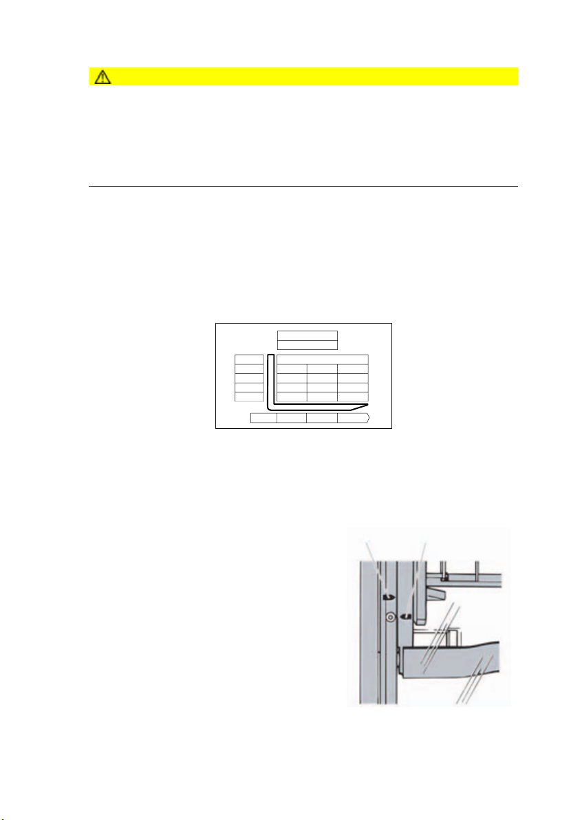
4.3 Truck capacity plate
CAUTION!
Accident risk from fork replacement
If you replace the forks with ones that differ from the originals, the capacity will
change.
XWhen replacing the forks you must attach an additional capacity plate to the truck.
XTrucks supplied without forks are given a capacity plate for standard forks (length:
1150 mm).
The capacity plate (22) gives the capacity (Q in kg) of the truck for a vertical mast.
The maximum capacity is shown as a table with a given load centre of gravity D (in
mm) and the required lift height H (in mm).
The capacity plate (22) of the truck indicates the truck's capacity with the forks as
originally supplied.
Example of how to calculate the maximum capacity:
850
1105
1250
Q (kg)
850
1105
1250
600
850
850
h3 (mm)
4250
3600
2900
D (mm) 500 600 700
For a load cente of gravity D of 600 mm and a maximum lift height h3 of 3600 mm the
maximum capacity is Q 1105 kg.
Lift height restriction
The arrow shape markings (42 and 43) on the
inner and outer masts show the driver when the
42 43
prescribed lift limits have been reached.
36
09.11 EN
Page 40

4.4 Attachment capacity plate
The attachment capacity plate is next to the truck's capacity plate and gives the
truck's capacity Q (in kg) in conjunction with the respective attachment. The serial
number for the attachment indicated on the capacity plate must match the data plate
of the attachment.
Z For loads with a centre of gravity greater than 500 mm, the capacities are reduced
by the difference of the altered centre of gravity.
5Stability
The truck's stability has been tested according to latest technological standards.
These take into account the dynamic and static tipover forces that can occur if used
correctly.
Stability can also be affected by the following factors:
–Tyre type
–Mast
–Attachment
– Transported load (size, weight and centre of gravity)
WARNING!
Loss of stability can cause accidents
Changing the components can alter the stability.
09.11 EN
37
Page 41

38
09.11 EN
Page 42

C Transport and Commissioning
1Transport
Transport can be carried out in two different ways, depending on the height of the
mast and the local conditions.
–Vertically, with the mast assembled (for low heights)
– Vertically, with the mast dismantled (for large heights), all mechanical connections
and hydraulic lines between the basic truck and the mast separated.
2Truck laden
2.1 Centre of gravity of the truck
WARNING!
Altering the centre of gravity can be hazardous
The overall centre of gravity can vary depending on the truck's equipment (especially
the mast version).
XFor masts with a low height the centre of gravity will move towards the
counterweight.
XFor masts with a greater height the centre of gravity will move towards the centre
of the truck.
The picture shows the approximate centre of
gravity location.
09.11 EN
39
Page 43
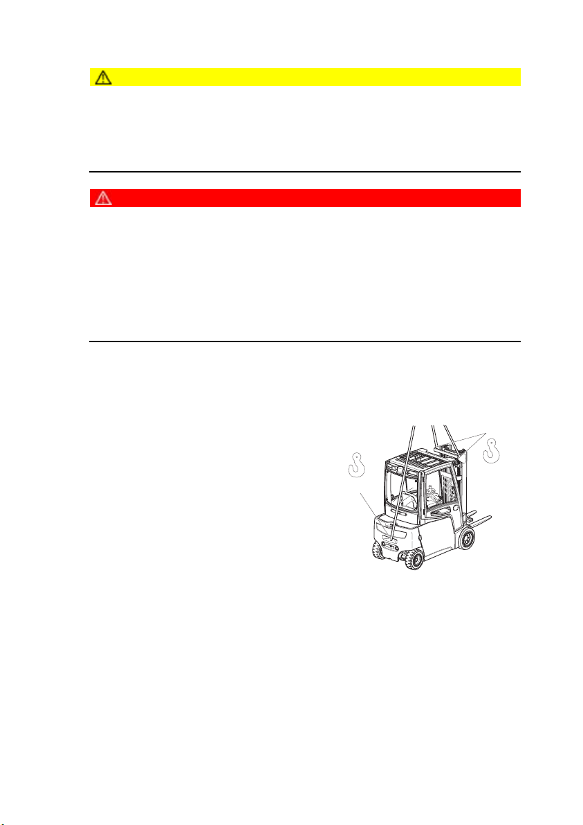
2.2 Lifting the truck by crane
CAUTION!
The mast can get damaged
XLoading by crane is only intended for the initial transport before the truck is used
for the first time.
XLoading must be carried out by specially trained staff in accordance with
recommendations contained in Guidelines VDI 2700 and VDI 2703
DANGER!
Crane slings can tear, resulting in accidents
XOnly use crane lifting gear with sufficient capacity.
XLoading weight = Net weight of truck (+ battery weight for electric trucks).
XThe mast must be tilted back fully.
XThe crane lifting gear on the mast must have a minimum clear length of 2 m.
XCrane slings should be fastened in such a way that they do not come into contact
with any attachments or the overhead guard when lifting.
XDo not stand under a swaying load.
Z Truck net weight: (see "Data plate" on page 35).
Lifting the truck by crane
Requirements
–Park the truck securely, (see "Parking the
truck securely" on page 99).
Procedure
•Secure the crane slings to the attachment
points (44) and (45.
• Raise and load the truck.
•Lower and deposit the truck carefully ((see
"Parking the truck securely" on page 99)).
•Secure the truck with wedges to prevent it
from rolling away.
This concludes the loading by crane.
45
44
40
09.11 EN
Page 44

2.3 Loading with another industrial truck
WARNING!
The truck can be damaged
The truck to be loaded can get damaged when loading with another industrial truck.
XOnly trained specialist personnel should load the truck.
XUse only trucks with sufficient capacity for loading.
XOnly for loading and unloading.
XThe forks of the second industrial truck must be sufficiently long
XTransporting over long distances prohibited.
Loading the truck with a second industrial truck
Requirements
– Park the truck securely, (see "Parking the truck securely" on page 99).
Procedure
•Raise the truck with the forks at the side between the axles.
•Raise the truck slightly and make sure it is securely positioned on the forks. If
necessary adjust or secure the forks with stops.
•Carefully load/unload the truck, (see "Lifting, transporting and depositing loads" on
page 107).
• Lower the truck slowly onto the ground and prevent it from rolling away.
The truck is now loaded.
09.11 EN
41
Page 45

3Securing the truck during transport
WARNING!
Accidental movement during transport
Improper fastening of the truck and mast during transport can result in serious
accidents.
XLoading must be carried out by specially trained staff in accordance with
recommendations contained in Guidelines VDI 2700 and VDI 2703 In each case
correct measurements must be made and appropriate safety measures adopted.
XThe truck must be securely fastened when transported on a lorry or a trailer.
XThe loading area must have clamp rings and a wooden floor to secure the retaining
wedges.
XUse wedges to prevent the truck from moving.
XUse only tensioning belts or tie-down straps or with sufficient strength.
Securing with a mast Securing without a mast
3
46
42
13
47
46
13
48
47
09.11 EN
Page 46

Securing the truck for transport
Requirements
–Position the truck securely on a lorry or trailer, (see "Parking the truck securely" on
page 99).
Tools and Material Required
–2 tensioning belts with tensioner
–Retaining wedges.
Procedure
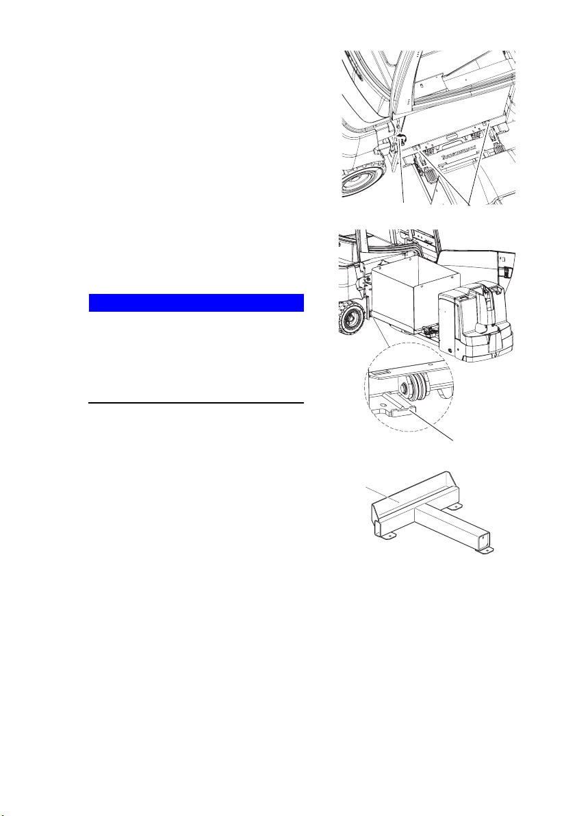
• Secure the truck with the tensioning belt (46) at the top cross member of the mast
(3) and the trailer coupling (13) or over the mud guard (48) and the trailer coupling
(13).
•Tighten the tensioning belt (46) with the tensioner (47).
The truck is now secured for transport.
09.11 EN
43
Page 47

4Using the Truck for the First Time
Safety Instructions for Assembly and Commissioning
WARNING!
Accident risk from incorrect assembly
The assembly of the truck at the application site, commissioning and driver training
must only be performed by the manufacturer's customer service representatives who
have been specially trained for these tasks.
XThe hydraulic lines may only be connected to the basic truck / mast interface when
the mast has been properly assembled.
XOnly then can the truck be started.
XIf several trucks have been delivered, make sure that the serial numbers of the load
handlers, masts and basic trucks always match.
CAUTION!
Only operate the truck with battery current. Rectified AC current will damage the
electronic components. Cable connections to the battery (tow leads) must be less
than 6 m long and have a minimum cross-section of 50 mm².
Preparing the truck for operation after delivery or transport
Procedure
•Check the equipment is complete.
• Check the hydraulic oil level, (see "Hydraulic system" on page 189).
•Install the battery if necessary, (see "Battery removal and installation" on page56).
•Charge the battery, (see "Charging the battery" on page51).
The truck can now be started, (see "Preparing the Truck for Operation" on page 87).
Z To operate the truck without its own drive system, (see "Operating the truck without
its own drive system" on page 146).
44
09.11 EN
Page 48

DBattery - Servicing, Recharging,
Replacement
1Safety Regulations Governing the Handling of Lead-Acid
Batteries
Maintenance personnel
Batteries may only be charged, serviced or replaced by trained personnel. This
operator manual and the manufacturer’s instructions concerning batteries and
charging stations must be observed when carrying out the work.
Fire protection
Do not smoke and avoid naked flames when handling batteries. Wherever an
industrial truck is parked for charging there shall be no inflammable material or
lubricants capable of creating sparks within 2 m around the truck. The room must be
ventilated. Fire protection equipment must be on hand.
Battery maintenance
The battery cell covers must be kept dry and clean. Terminals and cable shoes must
be clean, lightly greased with terminal grease and must be securely tightened.
Batteries with non insulated terminals must be covered with a non slip insulating mat.
CAUTION!
Before closing the battery panel make sure that the battery cable cannot be
damaged. There is a risk of short circuits with damaged cables.
Battery disposal
Batteries may only be disposed of in accordance with national environmental
protection regulations or disposal laws. The manufacturer’s disposal instructions
must be followed.
09.11 EN
45
Page 49

46
09.11 EN
Page 50

1.1 General notes on handling batteries
WARNING!
Batteries can be hazardous
Batteries contain an acid solution which is poisonous and corrosive. Above all avoid
any contact with battery acid.
XDispose of used battery acid in accordance with regulations.
XAlways wear protective clothing and goggles when working with batteries.
XDo not let battery acid come into contact with skin, clothing or eyes. If necessary,
rinse with plenty of clean water.
XIn the event of physical damage (e.g. skin or eye contact with battery acid) call for
a doctor immediately.
XSpilled battery acid should be neutralised immediately with plenty of water.
XOnly batteries with a sealed battery container may be used.
XFollow national guidelines and legislation.
WARNING!
Using unsuitable batteries can cause accidents
The weight and dimensions of the battery have a considerable effect on the
operational safety and capacity of the industrial truck. Changing the battery features
requires the manufacturer’s approval, as compensating weights are required if
smaller batteries are fitted. When replacing/installing the battery make sure the
battery is securely located in the battery compartment of the truck.
Park the truck securely before carrying out any work on the batteries ((see "Parking
the truck securely" on page 99)).
09.11 EN
47
Page 51

2Battery types
CAUTION!
Always use batteries with insulated covers or live components.
The battery weights are indicated on the battery data plate.
The truck will be equipped with different battery models, depending on the
application. The following table shows which combinations are included as standard:
Truck mode l Descriptio n Capacity
EFG 213 48V - 4PzS 460 Ah
EFG 215 48V - 4PzS 460 Ah
EFG 216k 48V - 5PzS 575 Ah
EFG 216 48V - 6PzS 690 Ah
EFG 218k 48V - 5PzS 575 Ah
EFG 218 48V - 6PzS 690 Ah
EFG 220 48V - 6PzS 690 Ah
EFG 316k 48V - 5PzS 575 Ah
EFG 316 48V - 6PzS 690 Ah
EFG 318k 48V - 5PzS 575 Ah
EFG 318 48V - 6PzS 690 Ah
EFG 320 48V - 6PzS 690 Ah
48
09.11 EN
Page 52

2.1 Battery dimensions
Battery 48 V
Dimension (mm)
Truck model
EFG 213/215 830 522 612 627 715
EFG 216k/
218k/
316k/318k
EFG 216/
218/220/
316/318/320
L max. W max. H1 +/-
2mm
H2 +/-
2mm
830 630 612 627 855
830 738 612 627 1025
Rated weight
(-5/+8%)in kg
09.11 EN
49
Page 53

3Exposing the battery
49
Requirements
– Park the truck securely, (see "Parking the truck securely" on page 99).
– Load handler lowered.
–Key switch set to OFF.
–Key removed.
–Set the Emergency Disconnect OFF.
Procedure
•Open the battery door(49) as far as the stop.
•Pull the battery connector(50) and let it drop down from the battery.
The battery is now exposed.
50
50
09.11 EN
Page 54

4Charging the battery
WARNING!
The gases produced during charging can cause explosions
The battery produces a mixture of nitrogen and hydrogen (electrolytic gas) during
charging. Gassing is a chemical process. This gas mixture is highly explosive and
must not be ignited.
XSwitch the charging station and truck off first before connecting/disconnecting the
charging cable of the battery charging station to/from the battery connector.
XThe charger must be adapted to the battery in terms of voltage and charge
capacity.
XBefore charging, check all cables and plug connections for visible signs of damage.
XVentilate the room in which the truck is being charged.
XThe battery cell surfaces must be exposed during charging to ensure adequate
ventilation.
XDo not smoke and avoid naked flames when handling batteries.
XWherever an industrial truck is parked for charging there shall be no inflammable
material or lubricants capable of creating sparks within 2 m around the truck.
XFire protection equipment must be on hand.
XDo not lay any metallic objects on battery.
XIt is essential to follow the safety regulations of the battery and charger station
manufacturers.
4.1 Charging the battery with a stationary charger
Z When charging, the battery door must be exposed by at least 200 mm to provide
sufficient ventilation.
Requirements
– Park the truck securely, (see "Parking the truck
securely" on page 99).
–Battery exposed.
–Charger switched off.
–Disconnect the battery connector(50) from the
truck connector (51).
Procedure
•Connect the battery connector(50) to the
charging lead (52)
of the stationary charger and turn on the charger.
The battery is now charged.
09.11 EN
51
50
52
51
Page 55

4.2 Charging the battery with an on-board charger
NOTE
Improper use of the on-board charger can cause material damage.
The on-board charger consisting of a battery charger and battery controller must not
be opened. For faults, contact the manufacturer’s service department.
XThe charger must only be used for batteries supplied by Jungheinrich or other
approved batteries provided it has been adapted by the manufacturer's service
department.
XBatteries must never be swapped from truck to truck.
XDo not connect the battery to two chargers simultaneously.
Mains connection
The mains lead may vary depending on the size of the on-board charger.
– On-board charger with 65 Ah: 16 A; 230 V; 3 pin
–On-board charger with 130Ah: 16A; 400V; 5pin
DANGER!
Risk of electric shock and burning
Damaged and unsuitable wires can cause electric shocks and can overheat, resulting
in fires.
XOnly use mains cables with a maximum length of 30 m.
XFully unreel the cable reel when using it.
XAlways use original manufacturer’s mains cables.
XInsulation safety, acid and caustic ratings must comply with the manufacturer's
mains cable.
52
09.11 EN
Page 56

Z When charging, the battery door must be exposed by at least 200 mm to provide
sufficient ventilation.
Charge the battery
Requirements
– Park the truck securely, (see "Parking the truck securely" on page 99).
–Battery exposed.
–Charger switched off.
–Disconnect the battery connector(50) from the truck connector(51).
Procedure
• Connect the on-board charger to the mains socket using the mains cable.
• Charging begins automatically.
•When the truck is switched on the charging status and the residual capacity are
shown on the display unit, (see "Display" on page 84).
The battery is now charged.
Z If the battery warning indicator (53) lights up after charging the battery, the battery
must be topped up with water when the truck is switched off.
53
am
100 %
pm
km/h
inch lbs
m kg eff code err
09.11 EN
53
Page 57

Battery charger LED displays
Green LED Meaning
Flashing Charging
Lit Charging complete
Red LED Meaning
Flashing Error
Battery controller LED displays
White LED Meaning
Flashing Radio network activated
Blue LED Meaning
Lit
Electrolyte level too low (measured
after each charge)
Yellow LED Meaning
Flashing rolling Charging
Lit Charge status
Red LED Meaning
Flashing Error
54
09.11 EN
Page 58

Float charge:
The compensation charge starts automatically when charging is complete.
Partial charging:
The charger is designed to automatically adapt to partially charged batteries. This
keeps battery wear to a minimum.
Z If a charging operation has to be
interrupted, press the button (54). Only
remove the mains connector when the
green LED goes out.
Charging starts again when the mains
cable is reconnected to the mains
socket.
54
09.11 EN
55
Page 59

5Battery removal and installation
WARNING!
Accident risk during battery removal and installation
Due to the battery weight and acid there is a risk of trapping or scalding when the
battery is removed and installed.
XNote the "Safety regulations for handling acid batteries" section in this chapter.
XWear safety shoes when removing and installing the battery.
XUse only batteries with insulated cells and terminal connectors.
XPark the truck on a level surface to prevent the battery from sliding out.
XMake sure the crane slings have sufficient capacity to replace the battery.
XUse only approved battery replacement devices (battery roller stand, replacement
trolley etc.).
XMake sure the battery is securely located in the truck's battery compartment.
56
09.11 EN
Page 60

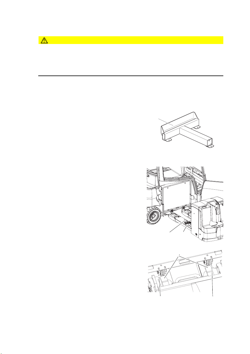
5.1 Battery holder assembly
CAUTION!
The battery holder can only be fitted to Jungheinrich AG pallet trucks (EJE) or
hand pallet trucks with notice signs.
Requirements
–EJE or hand pallet truck available with holes in accordance with assembly
instructions, (see "Assembly instructions" on page 58).
Procedure
•Open the safety catch(55).
•To do this press the pedals(56).
•Insert bent pins(57) into the forks of the EJE
or hand pallet truck.
•Push the battery holder down and fit the
bolts (58) in the holes.
•Close the safety catch(55).
•To do this press the pedals(56).
•Secure the locking plate(59) against theft with
4 screws (o).
56 57 58
55
59
09.11 EN
57
Page 61

5.1.1 Assembly instructions
1150
16
Ø
x4
Procedure
• Drill 4 holes with a 16 mm diameter into the EJE or hand pallet truck according to
the drill patterns.
•Make sure there is sufficient distance between the connecting rod and the bottom
of the forks.
458
130
90
Z Attach safety notices to the EJE.
58
09.11 EN
Page 62
5.2 Removal and installation using an EJE pallet truck with Snapfit
battery holder (o)
CAUTION!
Trapping hazard
Trapping hazard when replacing the battery.
XWhen replacing the battery do not reach between the battery and the chassis.
XWear safety shoes.
Removing the battery
Requirements
–Truck parked securely, (see "Parking the truck securely" on page99).
–Battery exposed, (see "Exposing the battery"
on page 50).
Tools and Material Required
– Battery trolley with four rollers
– EJE pallet truck with Snapfit battery holder
–Charging station intended for the battery
type (60) (o)
Procedure
•
•Close the safety catch(55).
•To do this press the pedals(56).
• Bring the EJE pallet truck approx. 200 mm
underneath the truck so that it is central with
the battery.
• Raise the forks of the EJE pallet truck until
they are just under the base of the truck.
60
55 56
•
•Push the ramps (61) into the plate recess and
align them with the chassis (62).
61
•Bring the EJE pallet truck up to the battery at
slow speed.
62 62
09.11 EN
59
Page 63
•
•Engage the safety catch(55) on the battery
replacement trolley.
•Make sure both safety catches(55) are
securely engaged in the battery
replacement trolley.
Z Do not raise the forks.
•Undo the battery lock(63).
•
• Remove the battery with the EJE pallet truck
travelling slowly as far as the stop (64).
•Raise the forks until the battery can be freely
pulled out of the battery compartment.
NOTE
Risk of material damage
Removing the battery can cause material
damage to the truck chassis.
XRaise the forks and avoid striking the
top or bottom parts of the chassis when
removing the battery.
•Bring the battery to the charging station for
charging.
•
•Place the battery carefully onto the charging
station (60)
• Undo the safety catch (55) and pull out the
EJE pallet truck.
The battery is now removed and positioned
securely for charging.
5563
64
60
60
09.11 EN
Page 64

Battery installation
Procedure
•
•Drive the EJE pallet truck and battery to the
truck.
• Deposit the battery replacement trolley with
the rollers (65) on the rails of the truck base.
•Lower the forks of the EJE pallet truck until the
battery is horizontal.
•Align the heights and push the forks of the EJE
pallet truck underneath the truck base.
NOTE
Risk of material damage
Inserting the battery can cause material
damage to the truck chassis.
XLower the forks and avoid striking the
top or bottom parts of the chassis when
inserting the battery.
• Insert the battery in the truck.
•Close the battery lock(63).
•
•Undo the safety catch(55).
•To do this press the pedals(56).
•Move the EJE pallet truck away from the truck.
•Close the battery door.
The battery is now inserted.
63
65
55 56
09.11 EN
61
Page 65

5.3 Removal and installation using a hand pallet truck with Snapfit
battery holder (o)
CAUTION!
Trapping hazard
Trapping hazard when replacing the battery.
XWhen replacing the battery do not reach between the battery and the chassis.
XWear safety shoes.
Removing the battery
Requirements
–Truck parked securely, (see "Parking the truck securely" on page99).
–Battery exposed, (see "Exposing the battery"
on page 50).
Tools and Material Required
– Battery trolley with four rollers
– Hand pallet truck with Snapfit battery holder
–Charging station intended for the battery
type (60) (o)
Procedure
•
•Close the safety catch(55).
•To do this press the pedals(56).
•Fully lower the hand pallet truck.
•Move the hand pallet truck up to the centre of
the battery until Snapfit contacts the truck
chassis.
60
•
•Raise the forks of the hand pallet truck until the
recess (66) is exposed.
• Move the hand pallet truck into the battery
compartment until the safety catches lock the
battery trolley.
•Make sure both safety catches(55) are
securely engaged in the battery
replacement trolley.
62
55
56
66
56
09.11 EN
Page 66

•
• Open the battery lock (63).
•Raise the hand pallet truck (approx. 20mm)
until the battery can be freely pulled out of the
battery compartment.
NOTE
Risk of material damage
Removing the battery can cause material
63
damage to the truck chassis.
XRaise the forks and avoid striking the
top or bottom parts of the chassis when
removing the battery.
• Remove the battery.
•Bring the battery to the charging station for charging.
•
•Place the battery carefully onto the charging
station (60)
60
The battery is now removed and positioned
securely for charging.
09.11 EN
63
Page 67

Battery installation
Procedure
•
•Move the hand pallet truck and battery to the
truck.
•Raise and move the hand pallet truck into the
battery compartment until the forks contact the
truck chassis.
•Deposit the battery trolley with the rollers(65)
on the base of the truck.
•Lower the forks of the hand pallet truck until
the battery is horizontal.
• Insert the battery in the truck.
•
•Close the battery lock(63).
• Lower the hand pallet truck.
•
•Undo the safety catch(55).
•To do this press the pedals(56).
• Move the hand pallet truck away from the
truck.
•Close the battery door.
The battery is now inserted.
65 67
63
55
56
64
09.11 EN
Page 68

5.4 Removal and installation using a multi-adapter (o)
CAUTION!
Trapping hazard
Trapping hazard when replacing the battery.
XWhen replacing the battery do not reach between the battery and the chassis.
XWear safety shoes.
Battery removal and installation
Requirements
–Park the truck securely, (see "Parking the truck securely" on page99).
–Battery exposed, (see "Exposing the battery" on page50).
–Battery disconnected.
Tools and Material Required
– Multi-adapter
– Battery trolley with six rollers
–Pallet truck with a fork length of 1150 mm
Procedure
•
•Push the pallet truck with the multi-adapter
as far as the stop (68) underneath the
battery.
•Set the multi-adapter to the straight-ahead
position using the alignment
(69).
68 69
•
•Raise the pallet truck until the multiadapter is up to
70
the height stop (70).
•Prevent the pallet truck from rolling away.
63
•Undo the battery lock(63).
•
• Pull the battery (71) out by its handle.
•The battery trolley must engage securely in
the safety catch (72).
• Lower the pallet truck slightly to move it.
71
The battery is now removed and can be taken
to the charging station for charging.
72
09.11 EN
65
Page 69

Z Battery assembly is the reverse order.
Release the retaining hook (72) using your foot. Insert the rollers of the battery
replacement trolley into the battery compartment guides and push the battery into
the battery compartment.
WARNING!
After inserting the battery close the battery lock and then lower the pallet truck.
66
09.11 EN
Page 70

5.5 Removal and installation using a worktable for crane loading (o)
CAUTION!
Trapping hazard
Trapping hazard when replacing the battery.
XWhen replacing the battery do not reach between the battery and the chassis.
XWear safety shoes.
Battery removal and installation
Requirements
–Park the truck securely, (see "Parking the truck securely" on page99).
–Battery exposed, (see "Exposing the battery" on page50).
–Battery disconnected.
Tools and Material Required
– Side table
– Battery trolley with six rollers
–Pallet truck with a fork length of 1360 mm
–Crane lifting gear
Procedure
•
•Push the hand pallet truck with the
worktable as far as the
stop (68) underneath the
battery.
68
•
•Raise the worktable and the pallet truck as
far as the stop (70).
•Undo the battery lock(63).
63
70
09.11 EN
67
Page 71

•
• Pull the battery (71) out by its handle.
• The battery trolley must engage securely in
the safety catch (72).
• Strap the crane lifting harness to the battery
container. The hooks must be fitted in such
71
a way that when the crane lifting harness is
slackened, they do not fall onto the battery
cells.
72
• Lift out the battery with the crane. The
battery replacement trolley remains secured
to the worktable via the safety catches (72).
The battery is now removed and can be taken to the charging station for charging.
Z Battery assembly is the reverse order.
Release the retaining hook (72) using your foot. Insert the rollers of the battery
replacement trolley into the battery compartment guides and push the battery into
the battery compartment.
WARNING!
After inserting the battery close the battery lock and then lower the pallet truck.
68
09.11 EN
Page 72

5.6 Removal and installation using a fork shoe (o)
CAUTION!
Trapping hazard
Trapping hazard when replacing the battery.
XWhen replacing the battery do not reach between the battery and the chassis.
XWear safety shoes.
Battery removal and installation
Requirements
–Truck parked securely, (see "Parking the truck securely" on page99).
–Battery exposed, (see "Exposing the battery"
on page 50).
–Battery disconnected.
–Battery lock released.
Tools and Material Required
–Fork shoe
–Second fork lift truck with a capacity to match
the battery weight. The battery weights are
indicated on the battery data plate.
–Battery trolley with two rollers
–Battery with cable guard(73)(o)
–Charging station intended for the battery type(60)(o)
Procedure
•
•Place the fork shoe onto the forks of a
second lift truck and secure it to the fork
carriage with a chain (74).
•Tilt the mast forward.
73
60
74
•
•Move the fork shoe up to the stop(75)
underneath the battery.
•Raise the fork carriage until the battery is
resting on the forks.
75
09.11 EN
69
Page 73

•
•Pull out the battery as far as the stop(76) on
the truck chassis.
•Raise the fork carriage.
•Tilt the mast back fully and bring the battery
to the charging station to be charged.
•
•Place the battery carefully on the charging
76
station (60).
60
The battery is now removed and positioned
securely for charging.
Z Battery installation is the reverse order.
Make sure the battery trolley rollers are inserted into the guides in the battery
compartment.
70
09.11 EN
Page 74

5.7 Removal and installation using a roller conveyor (o)
CAUTION!
Trapping hazard
Trapping hazard when replacing the battery.
XWhen replacing the battery do not reach between the battery and the chassis.
XWear safety shoes.
Battery removal and installation
Requirements
– Park the truck securely, (see "Parking the truck securely" on page 99).
–Battery exposed, (see "Exposing the battery" on page50).
–Battery disconnected.
–Battery lock released.
Tools and Material Required
– External roller guided replacement device
Procedure
•
Z Note the replacement device manufacturer’s
instructions.
• Bring the external replacement device up to
the truck.
•
• Pull the battery out with the external
replacement device
and transport it to the charging station
for charging.
•Deposit the battery securely.
The battery is now removed.
Z Battery assembly is the reverse order.
WARNING!
After inserting the battery close the battery lock.
09.11 EN
71
Page 75
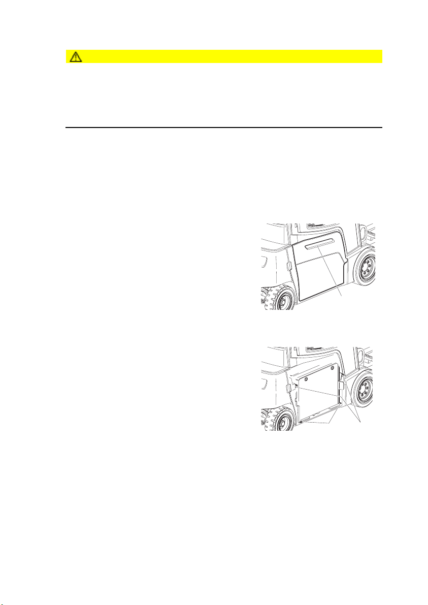
5.8 Hook-on battery door removal and installation (o)
CAUTION!
Trapping hazard
Trapping hazard when removing and installing the battery door.
XWhen removing and installing the battery door do not put your hands between the
door and the chassis.
XWear safety shoes.
Z Only for trucks with a roller conveyor.
Battery door removal
Requirements
– Park the truck securely, (see "Parking the truck securely" on page 99).
–Battery disconnected.
Procedure
•
•Open the battery door by moving the
handle (77) up.
•Lift the battery door slightly to the outside.
• Pull the battery door up
•Put the battery door down securely.
The battery door is now removed.
77
Battery door assembly
Requirements
–Park the truck securely, (see "Parking the
truck securely" on page 99).
–Battery disconnected.
Procedure
• Insert the battery door in the receptacles (78).
• Push the battery door onto the truck.
•Push the battery door down and engage it in
the bracket (79).
The battery door is now assembled.
78 79
Z If the battery door is not closed correctly, the truck will not be released for travel.
Information message (1918) is displayed.
72
09.11 EN
Page 76

EOperation
1Safety Regulations for the Operation of the
Forklift Truck
Driver authorisation
The truck may only be used by suitably trained personnel, who have demonstrated to
the proprietor or his representative that they can drive and handle loads and have
been authorised to operate the truck by the proprietor or his representative.
Driver's rights, responsibilities and rules of behaviour
The driver must be informed of his duties and responsibilities and be instructed in the
operation of the truck and shall be familiar with the operating instructions. The driver
shall be afforded all due rights.
Unauthorised use of truck
The driver is responsible for the truck during the time it is in use. The driver must
prevent unauthorised persons from driving or operating the truck. Do not carry
passengers or lift other people.
Damage and faults
The supervisor must be immediately informed of any damage or faults to the truck or
attachment. Trucks which are unsafe for operation (e.g. wheel or brake problems)
must not be used until they have been rectified.
Repairs
The driver must not carry out any repairs or alterations to the truck without the
necessary training and authorisation to do so. The driver must never disable or adjust
safety mechanisms or switches.
09.11 EN
73
Page 77

Hazardous area
WARNING!
Risk of accidents / injury in the hazardous area of the truck
The hazardous area is defined as the area in which a person is at risk due to truck
movement, lifting operations, the load handler (e.g. forks or attachments) or the load
itself. This also includes areas which can be reached by falling loads or lowering
operating equipment.
XInstruct unauthorised people to leave the hazardous area.
XGive a warning signal with plenty of time for people to leave.
XIf unauthorised personnel are still within the hazardous area stop the truck
immediately.
DANGER!
Accident risk
XThe driver must remain within the protected area of the overhead guard while the
truck is being operated.
Safety devices and warning labels
Safety devices, warning signs ((see "Indication Points" on page 33)) and warning
instructions in the present operating instructions must be strictly observed.
CAUTION!
Reduced headroom can cause injuries
XTrucks with reduced headroom are equipped with a warning label within the driver's
line of sight. The max. recommended body size indicated on this sign must be
observed.
XThe headroom is also reduced when you wear a protective helmet.
74
09.11 EN
Page 78
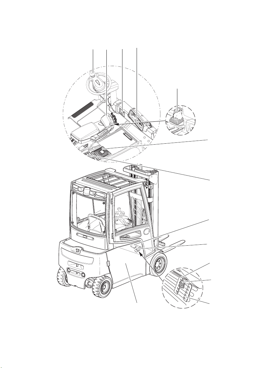
2Displays and Controls
80 81 82 83
81
84
85
86
87
88
86
90
09.11 EN
89
75
Page 79

Item Control /
Display
80 Steering wheel t Steers the truck.
81 SOLO-PILOT t Operates the following functions:
MULTI-PILOT o
82 Key switch t Switches control current on and off.
ISM access module o Switches the truck on.
Code lock
83 Dashboard control panel t Displays the battery capacity, service hours,
84 Emergency Disconnect
switch
85 Armrest / side pocket
control panel
86 Brake pedal t Provides infinitely variable braking control.
87 Accelerator pedal t Infinite travel speed control
88 “Reverse” accelerator
double pedal control
89 “Forward” accelerator
twin pedal control
90 On-board charger o Charges the truck
Function
– Fwd/rev. travel direction
– Lift/lower load handler
–Mast forward / reverse tilt
–Horn button
– Sideshifter left / right (o)
– Auxiliary hydraulics (o)
Removing the key prevents the truck from
being switched on by unauthorized
personnel.
errors, key warning indicators, wheel
position and travel direction.
Switches power supply on and off.
t Switches electric options on and off
o Applying the accelerator pedal moves the
truck forwards.
The travel speed is infinitely controlled.
o Applying the accelerator pedal reverses the
truck.
The travel speed is infinitely controlled.
Z *If the truck is equipped with an ISM access module refer to the “ISM Access
Module” operator manual.
76
09.11 EN
Page 80

80 81 82 83
81
84
85
86
87
88
86
90
09.11 EN
89
77
Page 81
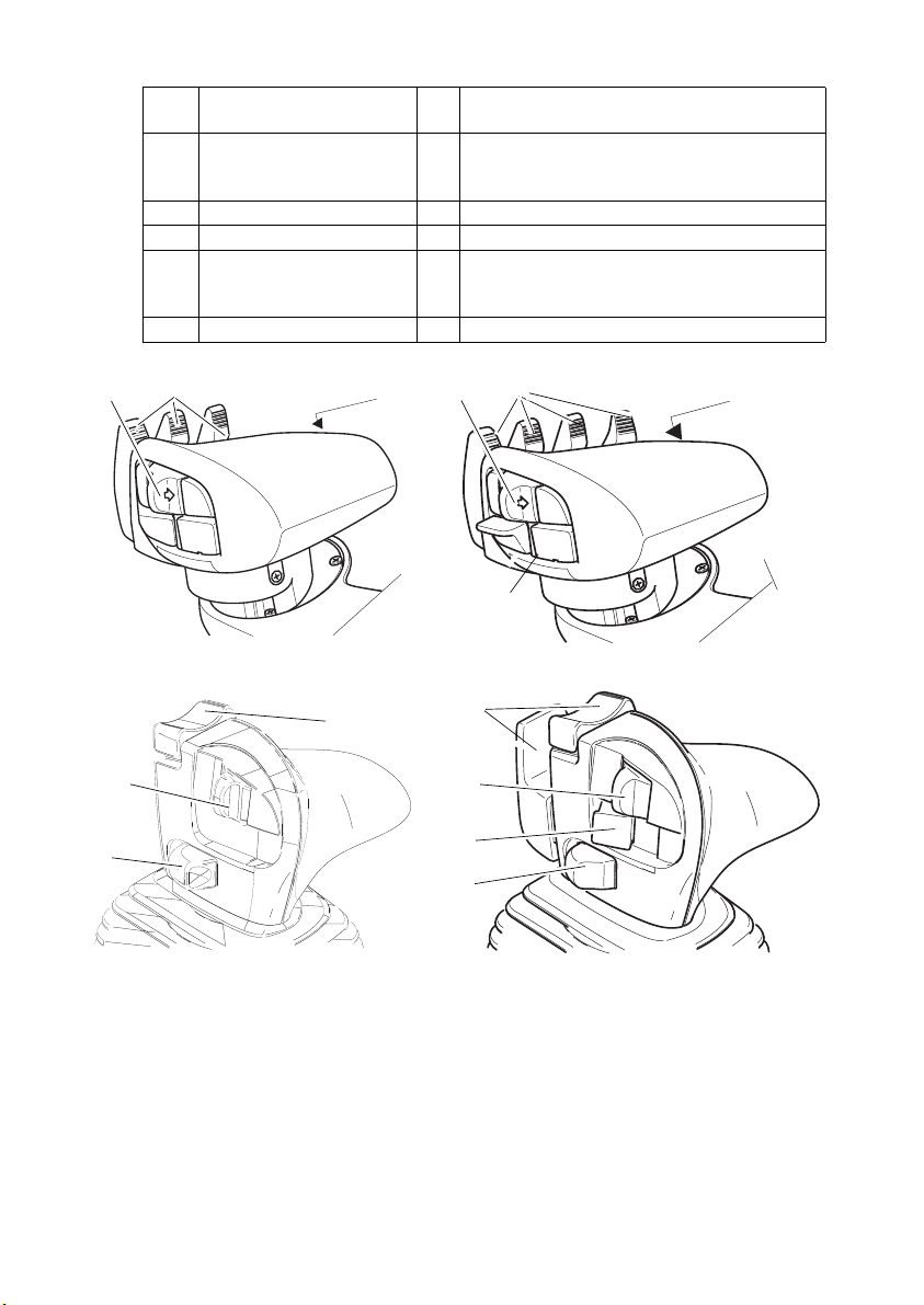
Item Control /
Function
Display
91 Travel direction switch
t Selects travel direction / neutral position.
(not available with dual
pedal control)
92 Lever t Lever for operating the hydraulic functions.
93 Horn t Activates an audible warning.
94 Additional hydraulic
function release button
o Activates the additional hydraulic functions
or hydraulics that require
acknowledgement.
95 Button o Hydraulic auxiliary function control button.
93
9291 93
91
92
92 9391
94
95
91
94
93
78
09.11 EN
Page 82
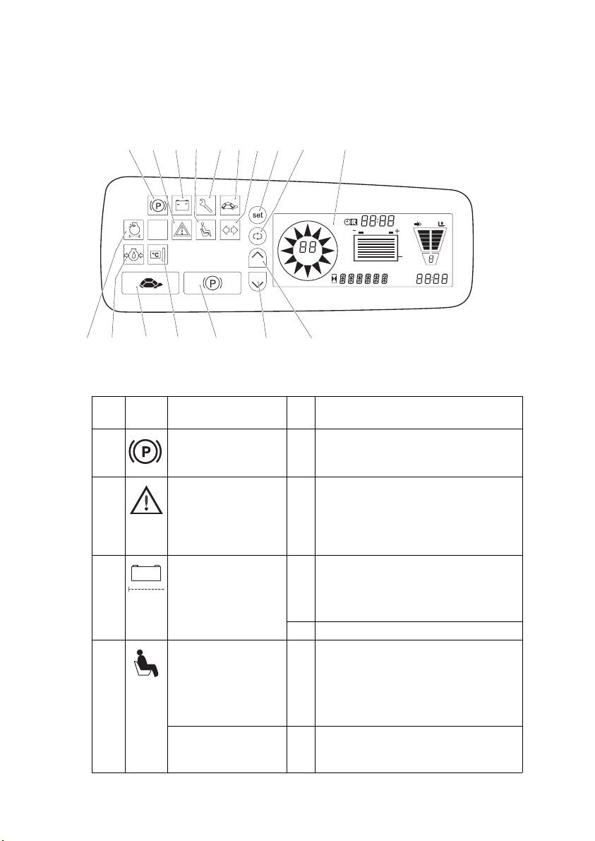
2.1 Control panel with display unit
The control panel display unit shows the operating data, the battery charge, the
service hours and error details and information. Pictograms in the left top section of
the dashboard control panel act as warning indicators.
96 97 53 98 99 10 101 102 103
105 106 107 108 109 110 111
Item Control /
Display
96 Parking brake
warning indicator
97 WARNING t WARNING
53 Battery indicator t WARNING
98 Seat switch warning
indicator
Seat belt lock
indicator (flashing
symbol)
09.11 EN
104
am
100 %
pm
km/h
inch lbs
m kg eff code err
Function
t Parking brake activated
– Truck operational, parking brake
applied
– Flashes for faults, an audible
warning sounds.
–Flashes when battery capacity is
less than 10%
–Electrolyte level too low
– Battery cells faulty
–Battery temperature too high
o On-board charger on radio network
t Seat switch not closed
–Truck operational, but driver’s seat
not occupied
Time monitoring expired
– Restart the truck
o – Truck operational, seat belt not
closed
79
Page 83

Item Control /
Function
Display
99 Service display t Service interval exceeded (1000
service hours) or annual FEM test due
(flashing indicator)
100 Crawl speed indicator t Slow travel activated (max. travel
speed 6 km/h)
101 Travel direction
o Right / left indicator lamps activated
display indicator lamp
102 Set button t Confirms the entries
103 Toggle button t Changes the “Time / Remaining Time”
display
104 Display t Displays the operating data ((see
"Display" on page 84) )
105 No function
106 No function
107 Crawl speed button t Switches crawl mode on and off
108 Control and motor
overtemperature
warning indicator
t –Lights up when the controllers and
motor overheat.
– Performance continually reduces
with respect to the temperature.
109 Parking brake button t Applies / releases parking brake
110 Pr ogra m sel ector t Selects the travel program (moves
down a level in the operating program
list.)
111 Pr ogra m sel ector t Selects the travel program (moves up
a level in the operating program list.)
80
09.11 EN
Page 84

96 97 53 98 99 10 101 102 103
104
km/h
inch lbs
m kg eff code err
am
100 %
pm
105 106 107 108 109 110 111
Z *Five operating programs with different performance levels are available to adapt
the travel and operating functions to the application at hand. Starting from operating
program 1 (limited acceleration and speed together with senstive application of the
operating functions), the performance levels increase to program 5 (maximum
performance for high throughput levels). If necessary the operating programs can
also be adapted or restricted to suit the customer. Please contact the
manufacturer’s service department.
09.11 EN
81
Page 85

2.2 Armrest control panel switch (o)
Function
Work lights
Front windscreen wipers
–Press 1x > intermittent,
–2x > fast,
–3x > off
– Hold down on the button > Switch on the windscreen
washing system
Rear windscreen wiper
–Press 1x > intermittent,
–2x > fast,
–3x > off
– Hold down on the button > Switch on the windscreen
washing system
Sideshift centre position
Lift cutout override
82
09.11 EN
Page 86

2.3 Side compartment control panel switch (o)
Function
Rear window heating
Beacon
Truck lighting
Parking light
Warning indicator
Lift cutout override
09.11 EN
83
Page 87

2.4 Display
112 113
am
100 %
pm
km/h
118
inch lbs
m kg eff code err
117
116
115
Item Function
112 – R emai ning time in th e for mat h ours : min utes
–Remaining charge time (o)
113 Time display (hours : minutes)
114 Operating program display
– Displays the travel program in use
115 Error display:
–If an error (Err) or a warning (Inf) occurs, the error or info
code is displayed.
–If several errors occur they are displayed alternately at
1.5 second intervals. A warning sounds.
116 Battery capacity display
– Battery discharge status
–Charge status display for on-board charger (o)
117 Hourme ter d ispla y
118 Travel direction, speed and wheel position display
–Indicates the pre-selected travel direction (forward or
reverse) or the position of the steered wheels.
–Flashing direction arrow = no travel direction selected
114
84
09.11 EN
Page 88

2.4.1 Battery discharge indicator
NOTE
Full discharge can damage the battery
The standard setting for the battery discharge indicator is based on standard
batteries. When using maintenance-free batteries (gel batteries), the display must be
reset.
XThis adjustment should only be made by the manufacturer’s service department.
XThe battery discharge indicator shows the battery’s residual capacity.
XCharge battery, (see "Charging the battery" on page 51).
The battery charge status is shown on the truck display via a battery symbol (116).
When a battery is discharged to the permissible discharge level, the battery symbol
(116) is displayed empty.
2.4.2 Battery discharge monitor
If the residual capacity falls below the required level, lifting is inhibited and the travel
speed is reduced. An message appears in the display. Lifting is only released when
the battery connected is at least 40% charged.
Z In order to complete the lift cycle, the key switch must be turned off and on again.
Lifting is then enabled for 30 to 40 seconds.
09.11 EN
85
Page 89

2.4.3 Residual time display
103
am
100 %
pm
km/h
inch lbs
m kg eff code err
Setting the residual time display
Procedure
•Press the toggle switch (103) for 3 seconds. This toggles the display between the
time and the residual time or the remaining charge time for an on-board charger
(o).
•Press the Shift key (103) for 8 seconds until the residual time display menu is
shown.
•Press the set key (103) to return to normal operating mode.
The time remaining to reach the residual capacity is displayed.
2.4.4 Hourmeter
The service hours are counted when the truck is switched on and the seat switch is
closed.
86
09.11 EN
Page 90

3Preparing the Truck for Operation
3.1 Checks and operations to be performed before starting daily
operation
WARNING!
Damage and other truck or attachment (special equipment) defects can result
in accidents.
If damage or other truck or attachment (special equipment) defects are discovered
during the following checks, the truck must be taken out of service until it has been
repaired.
XReport any defects immediately to your supervisor.
XTag out and decommission a faulty lift truck.
XOnly return the truck to service when you have identified and rectified the fault.
09.11 EN
87
Page 91

Checks before daily operation
Procedure
•Visually inspect the entire truck (in particular wheels,
wheel bolts and load handler) for damage.
•Check the fork stop (119) and fork retainer (120).
• Visually inspect the hydraulic system in the visible
119
area for damage and leaks.
• Make sure the driver’s seat is locked in position.
120
• Test the horn and reversing buzzer (o) where
applicable.
•Check that the load chart and warning labels are
legible.
•Test the controls and displays.
• Test the steering.
•Check the steer angle display (o), turn the steering wheel in both directions as far
as the stop and check that the wheel position is displayed on the control panel.
•Make sure the load chains are evenly tensioned.
•Test the seat belt. (The belt should block if extracted suddenly.)
•Test the seat switch. When the driver’s seat is vacated it should not be possible to
activate the hydraulics.
• Test the restraint system (o).
• Test the Drive Control (o).
•Raise the fork carriage without load beyond the reference point on the mast. The
slow travel symbol lights up on the display.
• Slowly apply the accelerator pedal on a clear route with good visibility. The
maximum speed should be reduced to walking pace (3 km/h).
•Test the lift/lower, tilt and if applicable the attachment hydraulic control functions.
•Check the accelerator pedal can move freely while the parking brake is applied and
the truck is idling, by pressing it several times.
•Visually inspect the battery attachment and cable connections.
•Check the battery lock is present and working.
•
• On trucks with lateral battery removal, check
the left and right stops (64) in the battery
compartment for damage.
•Check the fluid level of the window washer
system, (see "Preparing the truck for
operation" on page 97).
88
64
09.11 EN
Page 92

3.2 Entry and exit
Procedure
• Open the cab door (o)
•To enter and exit the cab, hold onto the handle
(121).
Z An additional step is provided for the driver position extension (o)
3.3 Trucks with reduced headroom X (o)
WARNING!
An unsuitable workplace can damage
your health
Failure to observe the recommended
body size can cause stress and endanger
the driver and may lead to lasting ill health
due to an unhealthy posture and
excessive strain on the driver.
XThe owner must ensure that truck
operators do not exceed the maximum
body size indicated.
XThe owner must check that the drivers
can sit in a normal and upright position
without having to strain.
121
09.11 EN
89
Page 93

3.4 Setting up the operator position
WARNING!
Accident risk
XDo not adjust the driver’s seat while travelling.
Procedure
•Before starting to travel, adjust the driver’s seat, steering column and armrest (if
necessary) so that all the controls are within reach and can be applied without
having to strain.
•Adjust the visibility aid equipment (mirrors, camera systems etc.) so that the
working environment can be clearly seen.
3.4.1 Adjusting the driver’s seat
WARNING!
Risk of accidents and damage to health
An incorrectly adjusted driver’s seat can result in accidents and damage to health.
XDo not adjust the driver’s seat while travelling.
XThe driver’s seat should lock in position after adjustment.
XCheck and adjust the individual driver’s seat setting before starting to use the truck.
XHold the weight setting lever (122) only by the recess, do not reach through
underneath the lever.
90
09.11 EN
Page 94

Adjusting the driver's weight
NOTE
To achieve optimal seat cushioning the
driver’s seat must be set to the driver’s
weight.
Set the driver's weight when the seat is
occupied.
Procedure
•Fold out the weight adjustment lever
(122) as far as it will go in the arrow
direction
•Move the weight adjustment lever (122) up and down to set the seat to a higher
weight.
•Move the weight adjustment lever (122) up and down to set the seat to a lower
weight.
123
122
126 127
125124
Z The driver's weight is correct when the arrow is in the middle of the display window
(123). The minimum or maximum weight setting is reached when you can feel a
return stroke on the lever.
•After setting the weight, move the lever (122) back in full.
The driver’s weight is now set.
Adjusting the backrest
Procedure
•Sit on the driver’s seat.
• Pull the lever (125) to adjust the backrest.
•Adjust the backrest tilt.
•Release the lever (125) again. The backrest is locked.
The backrest is now set.
Z Hold the weight setting lever (122) only by the recess, never reach through
underneath the lever.
09.11 EN
91
Page 95

Adjusting the seat position
122
CAUTION!
123
An unsecured driver's seat can cause
injury
An unsecured driver's seat can slide out of
its guide during travel, resulting in
accidents.
XThe driver's seat must be locked in
position.
XDo not adjust the driver’s seat while
travelling.
125124
Procedure
•Sit on the driver’s seat.
•Pull up the driver’s seat locking lever124 in the direction of the arrow.
• Push the driver’s seat forwards or backwards to the desired position
•Engage the driver’s seat locking lever (124) in position.
The seat position is now correctly set.
Switching the seat heating on and off
Procedure
•Press the seat heating switch (126).
Switch setting 1 = Seat heating on.
Switch setting 0 = Seat heating off.
126 127
Adjusting the lumbar vertebrae support (o)
Procedure
•Turn the hand wheel (127) to the required position.
Position 0 = no warping in lumbar vertebrae area.
Position 1 = increasing warping in upper lumbar vertebrae area.
Position 2 = increasing warping in lower lumbar vertebrae area.
The lumbar vertebrae support is now set.
92
09.11 EN
Page 96

3.4.2 Adjusting the steering column
128
Adjusting the steering column
Procedure
•Release the steering column stop (128).
•Set the steering column to the required position (height and angle).
•Fix the steering column stop (128) in position.
The steering column is now positioned.
3.4.3 Adjusting the arm rest
129 130
Adjusting the arm rest
Procedure
•Pull up the lock (130) and hold it in this position.
•Move the armrest (129) vertically and horizontally.
•Release the lock (130) at the desired position.
•Push the armrest slightly forward or back until it locks in position.
The armrest is now positioned.
09.11 EN
93
Page 97

3.5 Seat Belt
DANGER!
Travelling without a seat belt increases the risk of injury.
If the seat belt is not worn or is modified, personal injury can result.
XAlways put on the seat belt before starting the industrial truck.
XDo not modify the seat belt.
XDamaged or non-operational seat belts must be replaced by trained personnel.
XSeat belts must always be replaced after an accident.
XOnly original spare parts must be used for retrofits or repairs.
Z Protect the seat belt from contamination (e.g. cover it when the truck is idle) and
clean it regularly. Frozen belt locks or pulleys must be thawed out and dried to
prevent them from freezing up again.
The temperature of the warm air should not exceed +60 °C!
Starting the industrial truck on steep slopes
The automatic blocking system locks the belt in the retractor when the truck is
positioned on a steep slope. This prevents the belt from being pulled out of the
retractor.
Z Carefully drive the truck off the slope and then put on the belt.
94
09.11 EN
Page 98

4Industrial Truck Operation
4.1 Safety regulations for truck operation
Travel routes and work areas
Only use lanes and routes specifically designated for truck traffic. Unauthorised third
parties must stay away from work areas. Loads must only be stored in places
specially designated for this purpose.
The truck must only be operated in work areas with sufficient lighting to avoid danger
to personnel and materials. Additional equipment is necessary to operate the truck in
areas of insufficient lighting.
DANGER!
Do not exceed the permissible surface and spot load limits on the travel routes.
At blind spots get a second person to assist.
The driver must ensure that the loading dock / ramp cannot move or come loose
during loading / unloading.
NOTE
Loads must not be deposited on travel or escape routes, in front of safety
mechanisms or operating equipment that must be accessible at all times.
Travel conduct
The driver must adapt the travel speed to local conditions. The truck must be driven
at slow speed when negotiating bends or narrow passageways, when passing
through swing doors and at blind spots. The driver must always observe an adequate
braking distance between the forklift truck and the vehicle in front and must be in
control of the truck at all times. Abrupt stopping (except in emergencies), rapid U turns
and overtaking at dangerous or blind spots are not permitted. Do not lean out or reach
beyond the working and operating area.
Hazardous situations
If the truck is about to tip over, do not loosen the seat belt. The driver must not jump
off the truck. The driver must lean his upper body over the steering wheel and hold
on with both hands. Tilt your body in the opposite direction of fall.
Do not use a mobile phone or walkie-talkie without a handsfree device while
operating the truck.
09.11 EN
95
Page 99

Travel visibility
The driver must look in the direction of travel and must always have a clear view of
the route ahead. Loads that affect visibility must be positioned at the rear of the truck.
If this is not possible, a second person must walk alongside the truck as a lookout to
observe the travel route while maintaining eye contact with the driver. Proceed only
at walking pace and with particular care. Stop the truck as soon as you lose eye
contact.
Negotiating slopes and inclines
Negotiating slopes or inclines up to 15% is only permitted if they are specifically
designed as travel routes, are clean and have a non-slip surface and providing they
can be safely travelled along in accordance with the truck's technical specifications.
The truck must always be driven with the load unit facing uphill. The industrial truck
must not be turned, operated at an angle or parked on inclines or slopes. Inclines
must only be negotiated at slow speed, with the driver ready to brake at any moment.
Particular care is required when travelling near slopes and quay walls.
Negotiating lifts and docks
Lifts may only be entered if they have sufficient capacity, are suitable for driving on
and authorised for truck traffic by the owner. The driver must satisfy himself of the
above before entering these areas. The truck must enter lifts with the load in front and
must take up a position which does not allow it to come into contact with the walls of
the lift shaft. People travelling in the lift with the forklift truck must only enter the lift
after the truck has come to a halt and must exit the lift before the truck. The driver
must ensure that the loading ramp / bridge cannot move or come loose during loading
/ unloading.
Type of loads to be carried
The operator must make sure that the load is in a satisfactory condition. Loads must
always be positioned safely and carefully. Use suitable precautions to prevent parts
of the load from tipping or falling down. Prevent liquid loads from sloshing out.
Inflammable liquids (e.g. fused metal etc.) may only be transported with suitable
auxiliary equipment. Contact your authorized Jungheinrich customer adviser.
Z For safety instructions on the nature of loads to be carried with attachments,(see
"Lifting, transporting and depositing loads" on page 107).
Towing trailers
The truck may only be used occasionally to tow trailers, (see "Towing trailers" on
page 126)
96
09.11 EN
Page 100

4.2 Preparing the truck for operation
Switching on the truck
Requirements
–For checks and operations to be performed
before starting daily operation, (see "Checks
and operations to be performed before starting
daily operation" on page 87).
Procedure
• Unlock the Emergency Disconnect switch (84)
to do this
•Press the rocker in (s) and pull it up until you
feel the Emergency Disconnect switch
engaging.
• Insert the key in the key switch (82) and turn it clockwise as far as it will go to the
“I” position.
•Test the brake pedal and parking brake.
The truck is now ready for operation. The display (104) shows the remaining battery
capacity.
82 104
Z When you have pulled the EMERGENCY DISCONNECT and turned the key switch
to the right, the truck carries out a self test for approx. 3-4 seconds (tests the
controllers and motors). During this time the truck cannot move or lift. If the
accelerator or a lift mechanism lever is applied during this time, an information
message will be displayed.
84
09.11 EN
97
 Loading...