

Page 1
Operating instructions
50451814
ECR 327/336
10.05 -
03.07
Instrucciones de servicio
u
E
Page 2

0108.USA
Foreword
Safe operation of the industrial truck requires specialist knowledge, which is acquired
from this Operating Manual, from the training required by OSHA under 29 CFR
1910.178, and by training operators in factory installations and their functions. Safe
operation of the industrial truck requires knowledge that can be acquired from this
ORIGINAL OPERATING MANUAL. The information is set out concisely and in a clear
format. The chapters are organized alphabetically, each starting at page 1. The page
identifier consists of the chapter letter and page number.
For example: Page B2 is the second page of Chapter B.
Various types of industrial trucks are described in this Operating Manual. When
operating the truck and carrying out maintenance work, make certain you use the
description corresponding to your vehicle type.
Safety instructions and important information, and their relative importance, are
indicated by the following safety warning symbols and indicator words:
QwD This message indicates a hazardous situation that, if not avoided, will result
in death or serious injury. The instructions, safety precautions, actions, or
procedures relating to this message must be observed to avoid the risk of
death or serious injury.
QwW This message indicates a hazardous situation that, if not avoided, could
result in death or serious injury. The instructions, safety precautions, actions,
or procedures relating to this message must be observed to avoid the
potential risk of death or serious injury.
QwK This message indicates a situation that may lead to minor or moderate injury
if disregarded. The instructions, safety precautions, actions, or procedures
relating to this message must be observed to avoid the risk of minor or
moderate injury.
IMPORTANT This message appears if special precautionary measures are needed to
ensure that the correct action is taken or to prevent damage to or malfunction
of the industrial truck or a component.
NOTICE This message appears if special information, instructions, or indications are
needed with regard to procedures, equipment, tools, pressures, loads, and
other special data.
t Indicates component fitted as standard.
o Indicates optional extra.
Page 3

0108.USA
It is impossible for the manufacturer to foresee every possible operational
circumstance that could involve a potential danger. For that reason, the warnings in
this manual and on the equipment itself do not encompass all possible
circumstances. If you use a tool, procedure, working method, or operating technique
not expressly recommended by the manufacturer, you must make sure yourself that
it does not present a safety risk to you or to anyone else. You must also ensure that
the product will not be damaged or made unsafe through operation, lubrication,
maintenance, or the chosen repair measures.
The information, technical data, and illustrations contained in this document are
based on the information available at the time of publication. Specifications, torques,
pressures, measurements, settings, illustrations, and all other data are subject to
change at any time. These changes relate to the performance of the product. Before
executing a task, you should request the most up-to-date and comprehensive
information from the manufacturer / dealer. You can also obtain additional copies of
the manual from your dealer.
In the interests of technical advancement, the manufacturer reserves the right to
make changes, while retaining the essential features of the type of vehicle described,
without correcting this Operating Manual at the same time.
Copyright
Copyright of this operating manual remains with JUNGHEINRICH AG.
Jungheinrich Aktiengesellschaft
Am Stadtrand 35
22047 Hamburg - GERMANY
Phone: +49 (0) 40/6948-0
www.jungheinrich.com
Page 4

I 1
0705.USA
Table of contents
A Compliance with regulations -
Legislation and common sense
B Recognition and avoidance of risks
C Appropriate use
D Vehicle description
1 Description of use ............................................................................... D 1
2 Components ........................................................................................ D 2
3 Technical data ..................................................................................... D 3
3.1 Performance data ................................................................................ D 3
3.2 Dimensions ......................................................................................... D 4
3.3 Axle and drive wheel loads ................................................................. D 6
3.4 US standards ...................................................................................... D 15
3.5 Operating conditions ........................................................................... D 16
4 Position of signs and nameplates ...................................................... D 17
4.1 Nameplate, vehicle .............................................................................. D 18
4.2 Sign - Qmax (15) ................................................................................. D 19
4.3 Sign - Danger battery (16) ................................................................... D 19
4.4 Sign - Warning battery size (17) .......................................................... D 19
4.5 Sign - Warning stay clear (18) ............................................................. D 20
4.6 Sign - Warning jog button coast, left (20a) (o) ................................... D 20
4.7 Sign - Warning jog button coast, right (20b) (o) ................................. D 20
4.8 Sign - Warning stay clear stop truck (24) ............................................ D 21
4.9 Sign - Warning charger (25) ................................................................ D 21
4.10 Sign - Warning electrical device (27) .................................................. D 22
4.11 Sign - Warning coast system (28) (o) ................................................ D 22
Page 5

0705.USA
I 2
E Operation
1 Description of controls and indicators ................................................. E 1
2 Starting the vehicle .............................................................................. E 5
2.1 Preparing for operation ....................................................................... E 5
2.2 Driving, steering, braking .................................................................... E 6
2.3 Raising and lowering load units .......................................................... E 13
2.4 Switching off and securing the vehicle ................................................ E 14
2.5 Adjusting the fork height ...................................................................... E 14
3 Important general aspects affecting the safe use of the truck ............. E 15
3.1 Training, certification, and approval to use the truck ........................... E 15
3.2 Damage and repairs to the industrial truck ......................................... E 17
3.3 Aspects in relation to loading .............................................................. E 18
3.4 Operating environment ........................................................................ E 19
3.5 Safety devices and warning signs ....................................................... E 22
3.6 Lifting of people ................................................................................... E 23
4 Operating the industrial truck .............................................................. E 25
4.1 Safety regulations for industrial truck operators .................................. E 25
4.2 General operation of the truck ............................................................. E 25
4.3 Ensuring that the industrial truck is properly equipped ....................... E 28
4.4 Opening and closing railroad cars ....................................................... E 29
4.5 Safe loading and transportation .......................................................... E 30
4.6 Preventing overturning and tipping ..................................................... E 31
4.7 Supervising and securing the truck ..................................................... E 32
4.8 Lifting of people ................................................................................... E 32
5 Keypad (CANCODE) (o) .................................................................... E 34
5.1 Code lock ............................................................................................ E 34
5.2 Travel program .................................................................................... E 36
5.3 Parameters .......................................................................................... E 36
5.4 Parameter settings .............................................................................. E 37
5.5 Travel parameters ............................................................................... E 41
6 Information display (CANDIS) (o) ...................................................... E 42
6.1 Discharge monitor function ................................................................. E 43
6.2 Operating hours indicator .................................................................... E 43
6.3 Power-up test ...................................................................................... E 43
7 Discharge indicator (LEA) (t) ............................................................. E 44
8 Troubleshooting .................................................................................. E 45
Page 6

I 3
0705.USA
F Battery – Maintaining, recharging, replacing
1 Safety regulations for handling lead-acid batteries ............................. F 1
2 Battery type ......................................................................................... F 2
3 Uncovering the battery ........................................................................ F 3
4 Charging the battery ............................................................................ F 4
5 Removing and installing the battery .................................................... F 5
5.1 Removal, standard design .................................................................. F 5
5.2 Removal, "removal from side" (o) ...................................................... F 6
5.3 Installing the battery ............................................................................ F 6
G Industrial truck maintenance and troubleshooting
1 Operational safety and environmental protection ................................ G 1
2 Safety regulations for industrial truck maintenance ............................ G 1
3 Maintenance and inspection ............................................................... G 7
4 Maintenance checklist ........................................................................ G 8
5 Lubrication chart .................................................................................. G 10
5.1 Operating resources ............................................................................ G 11
6 Description of maintenance and servicing jobs ................................... G 12
6.1 Preparing the industrial truck for maintenance and servicing ............. G 12
6.2 Opening the front cover ....................................................................... G 13
6.3 Removing the motor cover .................................................................. G 13
6.4 Checking the hydraulic oil level ........................................................... G 14
6.5 Checking the electrical fuses .............................................................. G 15
6.6 Restarting the vehicle after cleaning or
maintenance work G 16
7 Extended shutdown of the industrial truck .......................................... G 16
7.1 Measures required before shutdown ................................................... G 16
7.2 Measures required during the shutdown period .................................. G 17
7.3 Restarting the vehicle after shutdown ................................................. G 17
8 Safety inspections at regular intervals and after exceptional events .. G 18
H Transportation and commissioning
1 Securing the vehicle during transportation .......................................... H 1
2 Handling by crane ............................................................................... H 1
3 Commissioning .................................................................................... H 1
3.1 Adjusting the support roller forces before start-up .............................. H 2
4 Non-automotive movement of the vehicle ........................................... H 4
Page 7

0705.USA
I 4
Page 8

A 1
0705.USA
A Compliance with regulations -
Legislation and common sense
In 1998, OSHA produced a report on its wide-ranging study into the use of powered
industrial trucks in industry. This report was published in the US Federal Register/
vol. 63, no. 230. In this report OSHA sets out the many reasons why employers are
required to train their employees in connection with the use of powered industrial
trucks and why untrained personnel must be prohibited from using industrial trucks
except in controlled operating conditions such as a training session. The report shows
how extremely important a training program as required by the OSHA guidelines is
for the safety of equipment and personnel in connection with the use of powered
industrial trucks. 29 CFR part 1910.178. In simple terms, thorough training prior to the
use of an industrial truck is extremely important and must take place before an
industrial truck is used, since accidents leading to injury and death or property
damage are almost always the consequence of disregarding the underlying risks held
by the use of industrial trucks or of ignoring safety instructions and safety precautions
designed to minimize or eliminate such risks. The OSHA training program specifically
addresses these risks. The evidence contained in the OSHA report demonstrates that
the statutory training requirements for operators and employers are based on
experience and general judgment.
Jungheinrich industrial trucks satisfy the requirements of 29 CFR 1910.178 and
ASME B 56.1. Jungheinrich representatives are always on hand to provide advice on
issues surrounding the loading, operation, use and maintenance of powered
industrial trucks.
According to the OSHA report, knowledge and skills to operate an industrial truck
powered by an electric drive are not innate in human beings. Quite the contrary: This
knowledge can only be acquired through theoretical and practical training. This
means that having an industrial truck which complies with statutory regulations and
standards, is only one half of the safety equation. It is the responsibility of you, the
operator, and your employer to be aware of your responsibilities and of all national
and regional regulations and laws governing training requirements and the safe use
of powered industrial trucks, not only because the law requires it but because it is a
matter of common sense.
Powered industrial trucks may only be operated by trained and tested persons.
Training programs must satisfy OSHA requirements and as a minimum
address the topics mentioned here.
Employers and operators should pay especial attention to the section in ASME
regulations B56.1 concerning the operator.
"Safe operation is the responsibility of the operator" ASME B56.1 – 2003, Part
II Section 5.1.1.
Page 9

0705.USA
A 2
Page 10

B 1
0705.USA
B Recognition and avoidance of risks
In its 1998 investigation into the use of powered industrial trucks, OSHA determined
the ways in which accidents commonly occur and the causes of these accidents.
OSHA concluded that considerable risks to operators themselves and to other people
in their immediate vicinity can be put down to the inadequate or non-existent training
of operating personnel. According to OSHA, incorrect and unsafe operation are the
principal causes of accidents in connection with powered industrial trucks and the
resulting injuries and fatalities. It is therefore no coincidence that in reviewing its own
research, OSHA found that in almost all cases, accidents were attributable to
situations or actions, which the operator, or the employer and the operator together,
could have influenced or could have done better. This finding was confirmed by a
simple check of the accident causes cited by OSHA. Of the 208 accidents
investigated involving powered industrial trucks, 184 of which were fatal accidents or
resulted in serious injuries, a full 50 percent of them were due to loading problems,
including overloading, unstable loads, dropped loads or incorrect lifting of loads. 25
percent of the cases involved the tipping or overturning of the truck. A further 20
percent of the accidents were caused by the truck falling from a platform or a trailer
or by persons falling from an elevated position in a truck. Although only 4% of the
accidents were due to an absence of training and instruction, OSHA nevertheless
noted that many accidents could also have been caused by inadequate training. For
example, the overturning of a vehicle could just as easily be caused by poor or
inadequate instruction of the operator with regard to the loading of the vehicle. Other
less frequent accident causes, which could nevertheless still have been avoided by
employers and operators, were excessive speeds and the use of inappropriate
equipment.
The following measures are, therefore, of vital importance:
– Operators must be trained and aptitude-tested before working with a powered
industrial truck.
– Operators must be physically, mentally and emotionally capable of operating a
powered industrial truck.
– Operators must possess and apply all practical knowledge in relation to the safe
loading and correct operation of the vehicle. The capacity limits of the machine
must be known and must never be exceeded.
– All circumstances which could cause the vehicle to tip or to overturn, must be
avoided. Attention must be paid in this regard to shifting centers of gravity, correct
loading and the safe transport of loads, and to anticipatory driving, taking account
of edges, bends, slopes, and other driving conditions.
– Without appropriate driver training and the correct type of truck, passengers should
never be carried nor people lifted under any circumstances. Furthermore, the
correct procedure for this must be observed.
– Traffic rules must always be observed. Drivers must always be aware of the
position of colleagues and of other trucks and must pay attention to local
conditions.
The manufacturer shall not be held liable for the consequences of the dismantling of
the industrial truck or for modifications outside the manufacturer's control.
Page 11

0705.USA
B 2
The manufacturer's liability is limited to the configuration of the machine or plant
described in the declaration of conformity. The manufacturer is absolved from all
liability if modifications or additions are made or equipment from another
manufacturer is used. In such a case the manufacturer's liability is transferred to the
user/customer.
This Operating Manual shall cease to be valid if the machine is modified by a
company outside our Group, even if original spare parts are used and our company
logo can still be seen on the machine.
Page 12

C 1
0705.USA
C Appropriate use
NOTICE This Operating Manual contains all necessary information for the transport,
commissioning, normal use, maintenance, and servicing of the industrial
truck it describes, in accordance with ASME B56.1-2003, UL 583, and ANSI
Z535.4-2002. You should read these instructions carefully to ensure the safe
and correct use of the industrial truck.
The industrial truck described in this Operating Manual is suitable for lifting and
transporting loads.
This vehicle must be used and maintained in accordance with the information set out
in this Operating Manual. Any other usage constitutes improper use and may lead to
damage or injury. In particular, overloading as a result of excessive weight or
unbalanced loads must be avoided. The maximum permissible loading capacity is
stated on the nameplate and on the load diagram sticker on the industrial truck. The
industrial truck may not be used in areas where there is a risk of fire or explosion, or
a corrosive or dusty atmosphere.
This Operating Manual must be kept available throughout the entire period of use of
the vehicle.
Duties of the owner: Depending on the context cited in this Operating Manual, the
user of a fork lift truck can refer to several people, including the owner of the truck,
anyone who leases or borrows the truck, and the operator as defined in ASME B56.1-
2003. Generally speaking, the employer is the user, whereas his or her employee will
frequently perform the duties of the operator as described in the OSHA regulations.
Every user must know and apply the applicable rules and regulations relating to the
use and operation of the truck. The Operating Manual applies to all users and is
aimed at the people who actually operate the truck.
The operator and owner must ensure that the industrial truck is used correctly and
only within its design limits, and that all health and safety risks to operators or third
parties are avoided. The relevant accident prevention regulations and all relevant
safety provisions, along with operating, servicing and maintenance instructions, must
also be followed. The operator and owner must also ensure that anyone using the
truck has read and understood this Operating Manual. The owner must ensure that
all operators of the truck have read and understood this Operating Manual and that
they have successfully completed all legally required training and aptitude testing
before working with the truck.
Operators and users should understand that the vehicle operation changes if the
functions of manually operated trucks are automated (for example, rail-mounted
trucks or trucks with inductive guidance), resulting in changes to performance
features and maintenance procedures and requiring additional safety precautions.
If a manually operated industrial truck is adapted to include an automatic function, the
implications of the automation on all other functions must be considered. Other
functions may also need to be automated to some degree.
NOTICE Failure to comply with the content of this Operating Manual shall invalidate
the warranty. The same shall apply if the customer and/or third parties repair
or modify the machine without the approval of our customer service
department.
Page 13
0705.USA
C 2
Attachment of accessories: The attachment or installation of accessories, and
modifications and/or additions to the hardware or software, which adversely affect or
change the nominal power, the safe operation, the emergency devices or other
functions of the industrial truck, are permissible only with the prior, express, written
approval of the manufacturer.
If such approval is granted, the nameplates, markings or warnings with regard to load
capacity, operation, and maintenance must be altered accordingly.
Local authority approval must be obtained if necessary.
Local authority approval does not, however, release the owner from his or her duty to
obtain approval from the manufacturer.
If the industrial truck is fitted with accessories, including fork extensions, the user
must ensure that the truck is labeled to identify the accessories and that the
approximate weight of the truck and the combined accessories is shown, together
with the load capacity of the truck and accessories at maximum lift with a laterally
centered load.
If the modifications are associated with alterations and repairs to the basic functions,
these changes must be made in accordance with the criteria and procedures set
down by the manufacturer.
The basic functions comprise the following elements:
– Steering (guidance)
– Travel speed
– Controller and sensors
– Lift and load influencing
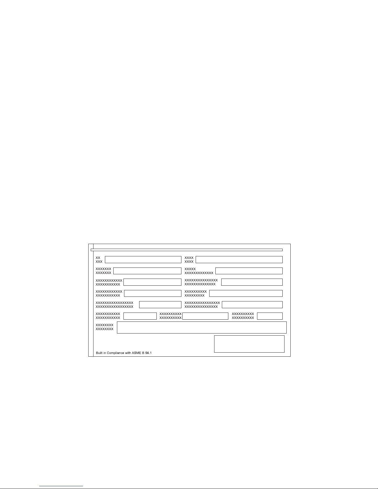
Nameplate: We recommend that you copy the details from the nameplate onto the
diagram below to ensure that this important data is available to the operator and that
this Operating Manual is not accidentally used for another machine.
The operator is responsible for ensuring that all nameplates, warning signs and
instruction signs are in place and are legible (see "Position of signs and nameplates"
in Chapter D).
QwW The use of an industrial truck involves certain risks, which cannot be fully
excluded even with the use of electrical devices; these risks can, however,
be minimized through intelligence, consideration, and common sense. It is,
therefore, essential that operators are qualified, diligent, and physically and
mentally fit, and have been thoroughly trained in the safe use of the machine
and in materials handling techniques.
Page 14

C 3
0705.USA
General instructions for operators and owners
QwW The instructions set out below apply to all users, including managers,
supervisors, operators, carriers, and employees working in the vicinity of
industrial trucks. The user is responsible for the safe use of this fork lift truck,
and employers and operators must work closely together to ensure that the
safety regulations applying to the use of the truck are observed and enforced.
1. This Operating Manual must be read before the industrial truck is used for the
first time and its content observed when using the truck.
2. The owner and operator must ensure that the industrial truck is used only for its
originally intended purpose. The owner and operator must NOT:
– Permit the industrial truck to be used for any other than its designated purpose
– Disable the safety systems
– Overload the industrial truck or use it if the arrangement of the load does not
match that shown in the load diagram
(see "Load capacity" in Chapter D)
– Use the industrial truck as a crane
– Lift or carry people
– Lock a control in position
– Ignore conventional practice in connection with the handling of loads
– Carry loads over people's heads
– Push or pull loads
– Take part in games, such as races
– Carry loads, which are not fully balanced
3. The owner and operator must check the load-bearing capacity of floors (to
prevent damage), shelves, and in general all gangways in which the industrial
truck may possibly be used.
4. Read the instructions on the signs attached to the industrial truck and ensure
that they are always legible.
5. This Operating Manual must be made available to all operators.
6. Ensure that only trained, tested, and responsible people who are capable of
operating the vehicle safely are allowed to operate the industrial truck.
7. Ensure that the industrial truck cannot be moved when it is not in use.
8. An industrial truck which is clearly not in good working order, must not be used.
9. The industrial truck must never be used to transport a load or to apply a force if
the maximum permissible operating load would be exceeded as a consequence.
10. The industrial truck must only be used in the manner for which the truck was
designed.
11. Read the safety instructions applicable for this industrial truck and comply with
these instructions without exception.
12. The manufacturer accepts no liability for consequences arising from the
dismantling of the industrial truck or from modifications outside the
manufacturer's control.
Page 15

0705.USA
C 4
13. The manufacturer's liability is limited to the configuration of the machine
described in the Declaration of Conformity. The manufacturer is absolved from
all liability if modifications or additions are made or equipment from another
supplier is used. In such a case the manufacturer's liability is transferred to the
user.
14. This Operating Manual shall cease to be valid if the machine is modified by a
company outside our Group, even if original spare parts are used and our
company logo still appears on the machine.
15. Exceptional operating conditions require additional safety precautions and
special operating instructions.
16. Supervision is essential to the safe use of powered industrial trucks.
17. The batteries must comply with the minimum and maximum weight range as
specified on the nameplate.
18. Wheel chocks and wheel locks (where fitted) are only suitable for holding the
industrial truck in the required position on a level surface.
QwW Extreme danger can arise from an overloaded truck, obstacles to free
passage of the load, impact with objects or pedestrians, poor maintenance,
and the use of equipment for which the industrial truck was not designed or
developed. Changes to the load, dimensions, coupling method, and/or
position, and also to the surface of the ground or the battery weight, can have
a negative impact on the load capacity and safe operation of the industrial
truck. Only stable or securely-fastened loads may be transported.
The user is responsible for ensuring the load is stable and secure. This should be
checked where necessary.
Page 16

D 1
0705.USA
D Vehicle description
1 Description of use
The vehicle is a three-wheel electric pedestrian pallet truck with operator stand-on
platform. Additional support rollers improve its cornering stability.
It is designed for use on level ground for the transport and picking of goods.
It can be used to pick up block pallets or stringer pallets that are beyond the range of
barrows or trolleys.
Loads can be stacked and unstacked and transported over relatively long distances.
The rated load capacity is stated on the nameplate or load plate (Qmax).
Page 17

0705.USA
D 2
2 Components
Item Designation Item Designation
1 t Tiller 8 t Forks
2 o Information display
(CANDIS)
9 t Battery connector/EMERGENCY
STOP
3 t Discharge indicator (EA) 10 t Battery
4 o Keypad
(CANCODE)
11 o
Leg cushion
5 o Access module ISM 12 t Support rollers
6 t Switch latch 13 t Drive wheel
7 o Safety guard 14 t Fixed operator stand-on platform
t = Fitted as standard o = Optional extra
1 2, 3 4,5 6 7
10
9
111312 1214
8
Page 18

D 3
0705.USA
3 Technical data
NOTICE The technical data specification complies with the German guidelines for
"Type sheets for industrial trucks".
Z
Subject to technical modification.
3.1 Performance data
*)On the extended fork version, the load center is in the center of the forks.
Designation ECR 327 ECR 336
Q Rated load capacity 6000 (2700) 8000 (3600) lb (kg)
c Load center distance with
standard fork length *
)
23.6 (600) 23.6 (600) in (mm)
Travel speed
with/without rated load
6.8/9.3 (11/15) 5.9/9.3
(9.5/15)
m/h (km/h)
Lift speed
with/without rated load
(0.39/0.50) (0.37/0.50) cm/s
Page 19

0705.USA
D 4
3.2 Dimensions
(all dimensions in inches (mm))
Designation Standard
l
2
Overall length at front 42.2 (1073)
h
13
Lowered height of fork 3.3 (83)
h
3
Lift height 5.7 (145)
b
1
Vehicle width 35.8 (910)
b
11
Track width 13.0 / 17.8 (331 / 451)
e
Fork width
Standard tip forks
Extended tip forks
9.0 (229)
9.8 (249)
a Safe distance 7.9 (200)
Service weight: see nameplate, vehicle
ll1yW
a
Standard tip forks
35.7 (908) 78.0 (1980) 49.4 (1254) 65.6 (1667)
41.7 (1060) 83.9 (2132) 55.4 (1407) 71.7 (1820)
47.8 (1213) 90.0 (2285) 61.5 (1561) 77.7 (1974)
53.7 (1365) 95.9 (2437) 67.5 (1714) 83.7 (2127)
59.7 (1517) 101.9 (2589) 73.5 (1866) 89.7 (2279)
95.7 (2432) 138.0 (3504) 109.6 (2783) 125.8 (3196)
102.8 (2610) 145.0 (3682) 116.6 (2961) 132.8 (3374)
Extended tip forks
83.7 (2127) 125.9 (3199) 81.5 (2069) 97.7 (2482)
92.8 (2356) 135.0 (3428) 81.5 (2069) 97.7 (2482)
95.7 (2432) 138.0 (3504) 81.5 (2069) 97.7 (2482)
102.8 (2610) 145.0 (3682) 81.5 (2069) 97.7 (2482)
Page 20

D 5
0705.USA
1475 mm ( 58.1")
y
e
124 mm (4.9")
415 mm
(16.3")
c
L
h
3
b
1
L
2
a
/
2
a
/
2
h
13
240 mm (9.4")
(L1)
b
11
b
5
x
W
a
Standard Tip Forks
x =185 mm (7.3")
Extendet Tip Forks Forks
x =592 mm (23.3") 2133 mm (84")
x =821 mm (32.5") 2362 mm (93")
x =897 mm (35.3") 2438 mm (96")
x =1075 mm (42.3") 2616 mm (103")
Page 21

0705.USA
D 6
3.3 Axle and drive wheel loads
Unladen vehicle, including 510 Ah battery
Drive wheel load
while moving
in fork direction
(level ground) in lb (kg)
1140 (517)
1232 (559)
1285 (583)
1032 (468)
1074 (487)
1276 (579)
1312 (595)
1376 (624)
1336 (606)
1321 (599)
1287 (584)
Drive wheel load
while moving
in drive direction
(level ground) in lb (kg)
1360 (617)
1453 (659)
1506 (683)
1274 (578)
1316 (597)
1519 (689)
1554 (705)
1596 (724)
1556 (706)
1541 (699)
1508 (684)
Load axle
in lb (kg)
637 (289)
584 (265)
573 (260)
569 (258)
567 (257)
606 (275)
619 (281)
686 (311)
756 (343)
783 (355)
840 (381)
Drive axle
in lb (kg)
1856 (842)
1949 (884)
2002 (908)
2046 (928)
2088 (947)
2291 (1039)
2326 (1055)
2092 (949)
2052 (931)
2037 (924)
2004 (909)
Vehicle weight
in lb (kg)
2493 (1131)
2533 (1149)
2575 (1168)
2615 (1186)
2654 (1204)
2897 (1314)
2945 (1336)
2778 (1260)
2809 (1274)
2820 (1279)
2844 (1290)
Forkoverhang
in inches (mm)
7.3 (185)
7.3 (185)
7.3 (185)
7.3 (185)
7.3 (185)
7.3 (185)
7.3 (185)
23.3 (592)
32.3 (821)
35.3 (897)
42.3 (1075)
Fork length
in inches (mm)
35.7 (908)
41.7 (1060)
47.8 (1213)
53.7 (1365)
59.7 (1517)
95.7 (2432)
102.8 (2610)
83.7 (2127)
92.8 (2356)
95.7 (2432)
102.8 (2610)
Page 22

D 7
0705.USA
Vehicle with 2700 kg load and 150 mm load carriage travel,
including 510 Ah battery
Drive wheel load
while moving in
fork direction
(level ground)
in lb (kg)
2262 (1026)
1836 (833)
2412 (1094)
2299 (1043)
2482 (1126)
3201 (1452)
3300 (1497)
2363 (1072)
2002 (908)
1929 (875)
1898 (861)
Drive wheel load
while moving in
drive direction
(level ground)
in lb (kg)
2482 (1126)
2057 (933)
2632 (1194)
2542 (1153)
2725 (1236)
3444 (1562)
3543 (1607)
2584 (1172)
2222 (1008)
2149 (975)
2119 (961)
Load axle
in lb (kg)
5467 (2480)
5933 (2691)
5399 (2449)
5254 (2383)
5110 (2318)
4634 (2102)
4583 (2079)
5650 (2563)
6043 (2741)
6127 (2779)
6182 (2804)
Drive axle
in lb (kg)
2978 (1351)
2553 (1158)
3128 (1419)
3313 (1503)
3496 (1586)
4215 (1912)
4314 (1957)
3080 (1397)
2718 (1233)
2646 (1200)
2615 (1186)
Vehicle weight
in lb (kg)
8446 (3831)
8485 (3849)
8527 (3868)
8567 (3886)
8607 (3904)
8849 (4014)
8898 (4036)
8730 (3960)
8761 (3974)
8772 (3979)
8796 (3990)
Load center
(LC)
in inches (mm)
19.7 (500)
23.6 (600)
23.6 (600)
26.9 (683)
29.9 (759)
47.9 (1216)
51.4 (1305)
41.9 (1064)
46.4 (1178)
47.2 (1200)
47.2 (1200)
Forkover-
hang
in inches
(mm)
7.3 (185)
7.3 (185)
7.3 (185)
7.3 (185)
7.3 (185)
7.3 (185)
7.3 (185)
23.3 (592)
32.3 (821)
35.3 (897)
42.3 (1075)
Fork length
in inches
(mm)
35.7 (908)
41.7 (1060)
47.8 (1213)
53.7 (1365)
59.7 (1517)
95.7 (2432)
102.8 (2610)
83.7 (2127)
92.8 (2356)
95.7 (2432)
102.8 (2610)
Page 23

0705.USA
D 8
Vehicle with 3600 kg load and 150 mm load carriage travel,
including 510 Ah battery
Drive wheel load
while moving in
fork direction
(level ground)
in lb (kg)
2615 (1186)
2048 (929)
2795 (1268)
2736 (1241)
2965 (1345)
3851 (1747)
3968 (1800)
2701 (1225)
2229 (1011)
2138 (970)
2103 (954)
Drive wheel load
while moving in
drive direction
(level ground)
in lb (kg)
2835 (1286)
2269 (1029)
3016 (1386)
2978 (1351)
3208 (1455)
4094 (1857)
4211 (1910)
2921 (1325)
2449 (1111)
2359 (1070)
2324 (1054)
Load axle
in lb (kg)
7099 (3220)
7705 (3495)
7000 (3175)
6803 (3086)
6612 (2999)
5968 (2707)
5899 (2676)
7297 (3310)
7800 (3538)
7901 (3584)
7961 (3611)
Drive axle
in lb (kg)
3331 (1511)
2765 (1254)
3512 (1593)
3750 (1701)
3979 (1805)
4866 (2207)
4982 (2260)
3417 (1550)
2945 (1336)
2855 (1295)
2820 (1279)
Vehicle weight
in lb (kg)
10430 (4731)
10470 (4749)
10511 (4768)
10551 (4786)
10591 (4804)
10833 (4914)
10882 (4936)
10714 (4860)
10745 (4874)
10756 (4879)
10780 (4890)
Load center
(LC)
in inches (mm)
19.7 (500)
23.6 (600)
23.6 (600)
26.9 (683)
29.9 (759)
47.9 (1216)
51.4 (1305)
41.9 (1064)
46.4 (1178)
47.2 (1200)
47.2 (1200)
Forkover-
hang
in inches
(mm)
7.3 (185)
7.3 (185)
7.3 (185)
7.3 (185)
7.3 (185)
7.3 (185)
7.3 (185)
23.3 (592)
32.3 (821)
35.3 (897)
42.3 (1075)
Fork length
in inches
(mm)
35.7 (908)
41.7 (1060)
47.8 (1213)
53.7 (1365)
59.7 (1517)
95.7 (2432)
102.8 (2610)
83.7 (2127)
92.8 (2356)
95.7 (2432)
102.8 (2610)
Page 24

D 9
0705.USA
Unladen vehicle, including 600 Ah battery
Drive wheel load
while moving
in fork direction
(level ground) in lb (kg)
1261 (572)
1358 (616)
1413 (641)
1162 (527)
1206 (547)
1415 (642)
1451 (658)
1510 (685)
1468 (666)
1455 (660)
1420 (644)
Drive wheel load
while moving
in drive direction
(level ground) in lb (kg)
1481 (672)
1578 (716)
1634 (741)
1404 (637)
1448 (657)
1658 (752)
1693 (768)
1731 (785)
1689 (766)
1675 (760)
1640 (744)
Load axle
in lb (kg)
668 (303)
611 (277)
597 (271)
591 (268)
586 (266)
619 (281)
633 (287)
703 (319)
776 (352)
800 (363)
860 (390)
Drive axle
in lb (kg)
1978 (897)
2075 (941)
2130 (966)
2176 (987)
2220 (1007)
2429 (1102)
2465 (1118)
2227 (1010)
2185 (991)
2172 (985)
2136 (969)
Vehicle weight
in lb (kg)
2646 (1200)
2685 (1218)
2727 (1237)
2767 (1255)
2806 (1273)
3049 (1383)
3097 (1405)
2930 (1329)
2961 (1343)
2972 (1348)
2996 (1359)
Forkoverhang
in inches (mm)
7.3 (185)
7.3 (185)
7.3 (185)
7.3 (185)
7.3 (185)
7.3 (185)
7.3 (185)
23.3 (592)
32.3 (821)
35.3 (897)
42.3 (1075)
Fork length
in inches (mm)
35.7 (908)
41.7 (1060)
47.8 (1213)
53.7 (1365)
59.7 (1517)
95.7 (2432)
102.8 (2610)
83.7 (2127)
92.8 (2356)
95.7 (2432)
102.8 (2610)
Page 25

0705.USA
D 10
Vehicle with 2700 kg load and 150 mm load carriage travel,
including 600 Ah battery
Drive wheel load
while moving in
fork direction
(level ground)
in lb (kg)
2390 (1084)
1962 (890)
2540 (1152)
2429 (1102)
2615 (1186)
3340 (1515)
3439 (1560)
2496 (1132)
2136 (969)
2061 (935)
2030 (921)
Drive wheel load
while moving in
drive direction
(level ground)
in lb (kg)
2610 (1184)
2183 (990)
2760 (1252)
2672 (1212)
2857 (1296)
3582 (1625)
3682 (1670)
2716 (1232)
2357 (1069)
2282 (1035)
2251 (1021)
Load axle
in lb (kg)
5492 (2491)
5959 (2703)
5423 (2460)
5276 (2393)
5130 (2327)
4647 (2108)
4597 (2085)
5670 (2572)
6060 (2749)
6146 (2788)
6202 (2813)
Drive axle
in lb (kg)
3106 (1409)
2679 (1215)
3256 (1477)
3444 (1562)
3629 (1646)
4354 (1975)
4453 (2020)
3212 (1457)
2853 (1294)
2778 (1260)
2747 (1246)
Vehicle weight
in lb (kg)
8598 (3900)
8638 (3918)
8679 (3937)
8719 (3955)
8759 (3973)
9001 (4083)
9050 (4105)
8882 (4029)
8913 (4043)
8924 (4048)
8948 (4059)
Load center
(LC)
in inches (mm)
19.7 (500)
23.6 (600)
23.6 (600)
26.9 (683)
29.9 (759)
47.9 (1216)
51.4 (1305)
41.9 (1064)
46.4 (1178)
47.2 (1200)
47.2 (1200)
Forkover-
hang
in inches
(mm)
7.3 (185)
7.3 (185)
7.3 (185)
7.3 (185)
7.3 (185)
7.3 (185)
7.3 (185)
23.3 (592)
32.3 (821)
35.3 (897)
42.3 (1075)
Fork length
in inches
(mm)
35.7 (908)
41.7 (1060)
47.8 (1213)
53.7 (1365)
59.7 (1517)
95.7 (2432)
102.8 (2610)
83.7 (2127)
92.8 (2356)
95.7 (2432)
102.8 (2610)
Page 26

D 11
0705.USA
Vehicle with 3600 kg load and 150 mm load carriage travel,
including 600 Ah battery
Drive wheel load
while moving in
fork direction
(level ground)
in lb (kg)
2745 (1245)
2178 (988)
2930 (1329)
2864 (1299)
3097 (1405)
3990 (1810)
4109 (1864)
2833 (1285)
2366 (1073)
2269 (1029)
2238 (1015)
Drive wheel load
while moving in
drive direction
(level ground)
in lb (kg)
2965 (1345)
2399 (1088)
3150 (1429)
3106 (1409)
3340 (1515)
4233 (1920)
4352 (1974)
3053 (1385)
2586 (1173)
2489 (1129)
2458 (1115)
Load axle
in lb (kg)
7121 (3230)
7727 (3505)
7017 (3183)
6825 (3096)
6631 (3008)
5981 (2713)
5911 (2681)
7317 (3319)
7815 (3545)
7923 (3594)
7978 (3619)
Drive axle
in lb (kg)
3461 (1570)
2895 (1313)
3646 (1654)
3878 (1759)
4112 (1865)
5004 (2270)
5123 (2324)
3549 (1610)
3082 (1398)
2985 (1354)
2954 (1340)
Vehicle weight
in lb (kg)
10582 (4800)
10622 (4818)
10664 (4837)
10703 (4855)
10743 (4873)
10985 (4983)
11034 (5005)
10866 (4929)
10897 (4943)
10908 (4948)
10933 (4959)
Load center
(LC)
in inches (mm)
19.7 (500)
23.6 (600)
23.6 (600)
26.9 (683)
29.9 (759)
47.9 (1216)
51.4 (1305)
41.9 (1064)
46.4 (1178)
47.2 (1200)
47.2 (1200)
Forkover-
hang
in inches
(mm)
7.3 (185)
7.3 (185)
7.3 (185)
7.3 (185)
7.3 (185)
7.3 (185)
7.3 (185)
23.3 (592)
32.3 (821)
35.3 (897)
42.3 (1075)
Fork length
in inches
(mm)
35.7 (908)
41.7 (1060)
47.8 (1213)
53.7 (1365)
59.7 (1517)
95.7 (2432)
102.8 (2610)
83.7 (2127)
92.8 (2356)
95.7 (2432)
102.8 (2610)
Page 27

0705.USA
D 12
Unladen vehicle, including 750 Ah battery
Drive wheel load
while moving
in fork direction
(level ground) in lb (kg)
1411 (640)
1526 (692)
1292 (586)
1345 (610)
1391 (631)
1314 (596)
1351 (613)
1404 (637)
1660 (753)
1647 (747)
1612 (731)
Drive wheel load
while moving
in drive direction
(level ground) in lb (kg)
1631 (740)
1746 (792)
1534 (696)
1587 (720)
1634 (741)
1590 (721)
1627 (738)
1647 (747)
1881 (853)
1867 (847)
1832 (831)
Load axle
in lb (kg)
769 (349)
694 (315)
672 (305)
659 (299)
653 (296)
666 (302)
675 (306)
763 (346)
836 (379)
860 (390)
919 (417)
Drive axle
in lb (kg)
2127 (965)
2242 (1017)
2306 (1046)
2359 (1070)
2405 (1091)
2637 (1196)
2674 (1213)
2418 (1097)
2377 (1078)
2363 (1072)
2328 (1056)
Vehicle weight
in lb (kg)
2897 (1314)
2937 (1332)
2978 (1351)
3018 (1369)
3058 (1387)
3300 (1497)
3349 (1519)
3181 (1443)
3212 (1457)
3223 (1462)
3247 (1473)
Forkoverhang
in inches (mm)
7.3 (185)
7.3 (185)
7.3 (185)
7.3 (185)
7.3 (185)
7.3 (185)
7.3 (185)
23.3 (592)
32.3 (821)
35.3 (897)
42.3 (1075)
Fork length
in inches (mm)
35.7 (908)
41.7 (1060)
47.8 (1213)
53.7 (1365)
59.7 (1517)
95.7 (2432)
102.8 (2610)
83.7 (2127)
92.8 (2356)
95.7 (2432)
102.8 (2610)
Page 28

D 13
0705.USA
Vehicle with 2700 kg load and 150 mm load carriage travel,
including 750 Ah battery
Drive wheel load
while moving in
fork direction
(level ground)
in lb (kg)
2549 (1156)
2116 (960)
2412 (1094)
2608 (1183)
2795 (1268)
3236 (1468)
3338 (1514)
2385 (1082)
2321 (1053)
2251 (1021)
2218 (1006)
Drive wheel load
while moving in
drive direction
(level ground)
in lb (kg)
2769 (1256)
2337 (1060)
2654 (1204)
2851 (1293)
3038 (1378)
3512 (1593)
3613 (1639)
2628 (1192)
2542 (1153)
2471 (1121)
2438 (1106)
Load axle
in lb (kg)
5584 (2533)
6056 (2747)
5505 (2497)
5348 (2426)
5201 (2359)
4694 (2129)
4638 (2104)
5734 (2601)
6127 (2779)
6208 (2816)
6265 (2842)
Drive axle
in lb (kg)
3265 (1481)
2833 (1285)
3426 (1554)
3622 (1643)
3810 (1728)
4559 (2068)
4661 (2114)
3399 (1542)
3038 (1378)
2967 (1346)
2934 (1331)
Vehicle weight
in lb (kg)
8849 (4014)
8889 (4032)
8931 (4051)
8970 (4069)
9010 (4087)
9253 (4197)
9301 (4219)
9134 (4143)
9164 (4157)
9176 (4162)
9200 (4173)
Load center
(LC)
in inches (mm)
19.7 (500)
23.6 (600)
23.6 (600)
26.9 (683)
29.9 (759)
47.9 (1216)
51.4 (1305)
41.9 (1064)
46.4 (1178)
47.2 (1200)
47.2 (1200)
Forkover-
hang
in inches
(mm)
7.3 (185)
7.3 (185)
7.3 (185)
7.3 (185)
7.3 (185)
7.3 (185)
7.3 (185)
23.3 (592)
32.3 (821)
35.3 (897)
42.3 (1075)
Fork length
in inches
(mm)
35.7 (908)
41.7 (1060)
47.8 (1213)
53.7 (1365)
59.7 (1517)
95.7 (2432)
102.8 (2610)
83.7 (2127)
92.8 (2356)
95.7 (2432)
102.8 (2610)
Page 29

0705.USA
D 14
Vehicle with 3600 kg load and 150 mm load carriage travel,
including 750 Ah battery
Drive wheel load
while moving in
fork direction
(level ground)
in lb (kg)
2906 (1318)
2332 (1058)
2793 (1267)
3038 (1378)
3276 (1486)
3884 (1762)
4006 (1817)
2720 (1234)
2549 (1156)
2456 (1114)
2425 (1100)
Drive wheel load
while moving in
drive direction
(level ground)
in lb (kg)
3126 (1418)
2553 (1158)
3036 (1377)
3280 (1488)
3519 (1596)
4160 (1887)
4281 (1942)
2963 (1344)
2769 (1256)
2676 (1214)
2646 (1200)
Load axle
in lb (kg)
7211 (3271)
7824 (3549)
7108 (3224)
6903 (3131)
6704 (3041)
6030 (2735)
5957 (2702)
7383 (3349)
7884 (3576)
7987 (3623)
8042 (3648)
Drive axle
in lb (kg)
3622 (1643)
3049 (1383)
3807 (1727)
4052 (1838)
4290 (1946)
5207 (2362)
5328 (2417)
3735 (1694)
3265 (1481)
3172 (1439)
3142 (1425)
Vehicle weight
in lb (kg)
10833 (4914)
10873 (4932)
10915 (4951)
10955 (4969)
10994 (4987)
11237 (5097)
11285 (5119)
11118 (5043)
11149 (5057)
11160 (5062)
11184 (5073)
Load center
(LC)
in inches (mm)
19.7 (500)
23.6 (600)
23.6 (600)
26.9 (683)
29.9 (759)
47.9 (1216)
51.4 (1305)
41.9 (1064)
46.4 (1178)
47.2 (1200)
47.2 (1200)
Forkover-
hang
in inches
(mm)
7.3 (185)
7.3 (185)
7.3 (185)
7.3 (185)
7.3 (185)
7.3 (185)
7.3 (185)
23.3 (592)
32.3 (821)
35.3 (897)
42.3 (1075)
Fork length
in inches
(mm)
35.7 (908)
41.7 (1060)
47.8 (1213)
53.7 (1365)
59.7 (1517)
95.7 (2432)
102.8 (2610)
83.7 (2127)
92.8 (2356)
95.7 (2432)
102.8 (2610)
Page 30

D 15
0705.USA
3.4 US standards
Continuous sound pressure level at ear level:
63 db(A)
determined by the ASME test procedure defined in
ASME B56.11.5
NOTICE The continuous sound pressure level is a value determined in accordance
with the standard, taking into account the sound pressure level while driving,
lifting and at idle. The sound pressure level is measured at ear level.
Vibrations: a
w,zS
= 3.08 ft/s2 (0.94 m/s2).
NOTICE The vibration acceleration acting on the body in the operating position is the
linearly integrated, weighted acceleration in the vertical direction. It is
determined by driving over shock waves at a constant speed.
Electromagnetic compatibility (EMC)
The manufacturer confirms compliance with the limit values for electromagnetic
interference and interference resistance and electrostatic discharge testing as set out
in the table below:
Interference resistance
The following limit values apply for industrial trucks/transportation systems:
Environmental phenomenon Test value Unit
1.1 Frequency
Electromagnetic field
Amplitude modulation
27-1000 *
10
80
MHz
V/m (unmodulated, rms)
% AM (1 kHz)
1.2 Frequency
Electromagnetic field
Pulse modulation
900 ± 5
10
50
200
MHz
V/m (unmodulated, rms)
% operating cycle
Repetition frequency Hz
1.3 Electrostatic
discharge
4 contact
8 air
discharge
kV (discharge voltage)
* The frequency range has been expanded to include low-frequency
interference in the wiring.
Page 31

0705.USA
D 16
NOTICE Very strong electromagnetic fields can adversely affect the performance of
the industrial truck. In the same way, machinery that is highly sensitive to
electromagnetic fields may also be adversely affected by the industrial truck.
Be sure that emitted interference from the industrial truck cannot interfere
with the operation of adjacent machinery.
NOTICE Electrical or electronic components and their configuration may not be
modified without the prior written approval of the manufacturer.
3.5 Operating conditions
Ambient temperature:
- during operation: 41°F (+5°C) through 104°F (+40°C)
Ambient temperature measured over 24 hours:
77°F (25°C), max.
Maximum indoor humidity 70%, without condensation
NOTICE Industrial trucks intended for use in environments with temperatures below
41°F (5°C) or in refrigerated warehouses with extreme temperature or
humidity variations require special equipment and approval.
NOTICE If the vehicle is to be used for extended periods at temperatures below 32°F
(0°C), we recommend that you fill the hydraulic system with a low-viscosity
oil in accordance with the manufacturer's instructions.
Page 32

D 17
0705.USA
4 Position of signs and nameplates
NOTICE The vehicle nameplate (23) can be accessed by opening the front cover (see
Chapter F).
Item Designation
15 Sign - Qmax
16 Danger battery 2x (1x opposite)
17 Warning battery size 2x (1x opposite)
18 Warning stay clear
19 Attachment point for handling by crane
20a Warning jog button coast, left (o)
20b Warning jog button coast, right (o)
21 Nameplate, battery
22 Attachment point for jack
23 Nameplate, vehicle
24 Warning stay clear stop truck
25 Warning charger
26 Vehicle serial number
27 Warning electrical device
28 Warning coast system (o)
16
20a
20b
25
19
22
23
23
26
28
27
19
22
17
21
24
15
18
opposite
(not shown)
Page 33

0705.USA
D 18
4.1 Nameplate, vehicle
NOTICE In the event of queries about the vehicle or when ordering spare parts, please
quote the serial number (30).
Item Designation Item Designation
29 Model 37 Manufacturer
30 Serial no. 38 Battery code
31 Rated load capacity 39 Battery weight, min./max.
32 Battery voltage 40 Drive output
33 Empty weight without battery 41 Load center distance
34 Residual load capacity 42 Year of manufacture
35 Lift height, max. 43 Option
36 Manufacturer's logo
37
36
3933
4032
4131
4230
4329
38
35
34
Page 34

D 19
0705.USA
4.2 Sign - Qmax (15)
4.3 Sign - Danger battery (16)
4.4 Sign - Warning battery size (17)
Qmax
6000 lbs
Page 35

0705.USA
D 20
4.5 Sign - Warning stay clear (18)
4.6 Sign - Warning jog button coast, left (20a) (o)
4.7 Sign - Warning jog button coast, right (20b) (o)
Page 36

D 21
0705.USA
4.8 Sign - Warning stay clear stop truck (24)
4.9 Sign - Warning charger (25)
Page 37

0705.USA
D 22
4.10 Sign - Warning electrical device (27)
4.11 Sign - Warning coast system (28) (o)
Page 38

E 1
0705.USA
E Operation
1 Description of controls and indicators
Item Control or indicator
Function
1 Switch latch t Switches the control current on and off. Remove
the key to prevent the vehicle being switched on by
unauthorized persons.
2 Discharge indicator (EA) t Displays the battery capacity
3 Information display (CANDIS) o Operating hours indicator
Shows the residual battery capacity and the
number of operating hours already completed by
the vehicle
4 Keypad (CANCODE) o Code settings, access authorization
Travel program enabling
5 Access module ISM o Starts/switches off the vehicle.
Displays important information, prompts, shock
events, and error messages.
Sets date and time.
6 Tiller t Swiveling tiller; steering and braking
7 Jog button o Travel switch for travel in tiller direction. Coasting
at 5.6 km/h (3.5 mph).
8 Travel regulator t Controls the direction of travel and speed (see
Section 4.2).
9 "Down" rocker switch t Lowers the fork.
10 "Up" rocker switch t Raises the fork.
11 Anti-collision button t Safety function. Automatically moves the vehicle
for approximately 3 s in the direction of travel (R)
and then switches it off until the travel regulator is
moved briefly to neutral.
12 Warning signal button (horn) t Sounds the warning signal.
13 Tiller locking lever o Locks the tiller in the travel position.
14 Jog button o Travel switch for travel in tiller direction. Coasting
at 5.6 km/h (3.5 mph).
15 Brake button o Brakes the vehicle mechanically.
16 High-speed button t Moves the vehicle in ride-on mode at 15 km/h,
max. (9.3 mph) in the tiller direction or 9.0 km/h,
max. (5.6 mph) in the fork direction.
t = Fitted as standard o = Optional extra
Page 39

0705.USA
E 2
12
12
16
16
10
17
9
18
10 11 10
99
88
77
12
6
2, 3 4, 5 1
141315
19
14 15
R
Page 40

E 3
0705.USA
Item Control or indicator
Function
17 Coast LED o Flashes:
– when a jog button is pressed and the vehicle is
coasting.
Lights up:
– when the battery capacity is down between 30%
and 0% with a standard battery.
– when the battery capacity is down between 40%
and 0% with a maintenance-free battery.
18 Jog button o Travel switch for travel in tiller direction. Coasting
at 5.6 km/h (3.5 mph).
19 Battery connector
(EMERGENCY STOP)
t The electric circuit is broken, all electrical functions
switch off and the vehicle brakes are automatically
applied.
t = Fitted as standard o = Optional extra
Page 41

0705.USA
E 4
12
12
16
16
10
17
9
18
10 11 10
99
88
77
12
6
2, 3 4, 5 1
141315
19
14 15
R
Page 42

E 5
0705.USA
2 Starting the vehicle
QwW Before the vehicle can be started, operated or used to lift a load unit, the
driver must ensure that there is nobody in the danger zone.
Daily checks and actions before startup
– Visually inspect the entire vehicle (especially wheels and load-handling equipment)
for signs of damage.
– Check for steering play.
– Visually inspect the battery fixings and cable connections.
2.1 Preparing for operation
– Insert the key in the switch latch (1) and turn it clockwise to the "I" position.
Or:
– On vehicles without a switch latch, enter the enable code via the CANCODE (4, o).
On delivery, the CANCODE start PIN is factory set to 2580. Enter the code via the
keypad and press the Set button to confirm.
– Check that the warning signal (horn) (12) is working correctly.
The vehicle is now ready for use. The discharge indicator (EA) (2) shows the charge
level of the battery.
On vehicles with an information display (CANDIS) (3, o), the remaining battery
capacity is displayed.
2, 312 12 4, 5
1
Page 43

0705.USA
E 6
2.2 Driving, steering, braking
QwW Extra care must be taken when driving and steering, especially outside the
perimeter of the vehicle.
In ride-on mode, keep an adequate distance from the vehicle.
Emergency stop
– Pull out the battery connector (19).
All electrical functions are switched off. The magnetic brake is applied and brakes the
vehicle with the highest brake step.
Driving
IMPORTANT Do not drive the vehicle unless all covers are closed and properly locked.
The main direction of travel is travel in the tiller direction (V). Extra care must
be taken when traveling in the load direction (R).
NOTICE Travel in the load direction (R) should be limited to shunting and to picking up
and setting down loads.
– Prepare for operation (see Section 2.1).
– Move the tiller (6) in the travel range "F".
– Turn the travel regulator (8) in the desired direction of travel (forward (V) or
backward (R)).
The vehicle starts moving in the chosen direction. The speed of travel is controlled
with the travel regulator (8). The maximum speed is 5.6 km/h (3.5 mph). If the highspeed button (16) is held down (t) in ride-on mode, the maximum speed of travel is
15 km/h (9.3 mph) in the tiller direction (V) and 9 km/h (5.6 mph) in the fork direction
(R).
R
R
V
8
6
13
19
16
F
V
B
B
Page 44

E 7
0705.USA
Press the high-speed button and release (o, parameter setting): If the high-speed
button (16) is pressed and released in ride-on mode, the maximum speed of travel is
15 km/h (9.3 mph) in the tiller direction (V) and 9 km/h (5.6 mph) in the fork direction
(R). If the travel regulator (8) is reset and the speed of travel drops to 0, high-speed
travel is deactivated. The maximum vehicle speed is then reset to 5.6 km/h (3.5 mph)
and the high-speed button must be pressed again.
Maneuvering in tight spaces (t): If there is no room to move the tiller in the travel
range "F" in order to start the vehicle (vehicle with tiller against obstacle), press the
high-speed button (16) and move the travel regulator (8) at the same time. The
vehicle starts to move at creep speed.
Steering
QwW In tight bends the driver is standing over the outer perimeter of the vehicle.
– Move the tiller (6) to the left or right.
Braking
QwW The vehicle's braking response largely depends on the travel surface
conditions. The driver should adapt his or her driving style accordingly.
The vehicle can be braked in three ways:
– With the service brake (brake for emergencies and hazardous situations)
– With the plug brake
– With the coasting brake
Braking with the service brake:
IMPORTANT Use this brake in an emergency or hazardous situation.
– Move the tiller (6) to one of the braking ranges (B).
The travel motor is braked with the motor brake. In borderline cases the magnetic
brake is automatically applied.
When the vehicle is stationary, the magnetic brake acts as a parking brake.
IMPORTANT If the tiller is released, it moves to the upper braking range (B).
Vehicle with locking tiller (13, o):
– Move the tiller to the lower or upper braking range B (the lock is released if the tiller
is moved toward the upper braking range B).
Page 45

0705.USA
E 8
Braking with the plug brake:
– Turn the travel regulator (8) in the opposite direction of travel until the vehicle is
stationary.
The vehicle is braked by reversal. When the vehicle is stationary, the magnetic brake
is applied.
Braking with the coasting brake
– Release the travel regulator or move it to the 0 position. The vehicle is braked
regeneratively until it is stationary. When the vehicle is stationary, the magnetic
brake is applied.
NOTICE The braking force is adjustable (parameter setting)
R
R
V
8
6
13
19
16
F
V
B
B
Page 46

E 9
0705.USA
Traveling with the jog button (7, o / 14, o / 18 o)
QwW Extra care must be taken when driving and steering, especially outside the
perimeter of the vehicle.
In ride-on mode, keep an adequate distance from the vehicle.
Vehicle tiller without locking lever with coasting brake (o)
– Move the tiller to the travel position (F).
– Press the jog button (7, o).
The vehicle starts moving at 5.6 km/h (3.5 mph), max., in the direction of travel V (with
button 14,
o only if the tiller is in the upright position).
– Release the jog button (7, o).
NOTICE The coasting brake is applied when you release the JOG button.
V
7
14
15
18
15
14
F
8
B
B
Page 47

0705.USA
E 10
Vehicle tiller with locking lever (13, o)
NOTICE In ride-on mode or order picking mode the tiller can be locked in the travel
position with the locking lever (13).
– Pull the tiller locking lever (13) up.
– Move the tiller down until it locks.
– When the tiller is locked, the vehicle is in coasting mode.
– Press the jog button (7, o / 14, o).
The vehicle starts moving in the direction of travel V at 5.6 km/h (3.5 mph), max.
– Release the jog button (7, o / 14, o).
The vehicle coasts for a predefined distance and is then braked automatically.
To brake the vehicle during coasting:
– Move the tiller to the lower or upper braking range B (the lock is released if the tiller
is moved toward the upper braking range B)
or
– Press the brake button (15, o)
NOTICE The LED (17) flashes when the vehicle is in coasting mode.
V
7
13
14
15
15
14
F
B
B
Page 48

E 11
0705.USA
Vehicle tiller without locking lever in coasting mode (o)
NOTICE To activate the coasting brake for the first time, move the tiller to the travel
position and press the JOG button.
– Press the jog button (7, o / 14, o / 18, o).
The vehicle starts moving at 5.6 km/h (3.5 mph), max., in the direction of travel V (with
button 14, o only if the tiller is in the upright position).
– Release the jog button (7,
o / 14, o / 18, o).
The vehicle coasts for a predefined distance (configurable) and is then braked
automatically.
V
7
14
15
18
15
14
F
8
B
B
Page 49

0705.USA
E 12
Z
Once the JOG button has been pressed, coasting mode remains active for a
predefined period. To activate coasting mode again, move the tiller to the travel
position again and press the JOG button.
QwW If the tiller is released in the upper braking range B, the vehicle is not braked.
To brake the vehicle during coasting:
– Move the tiller to the lower braking range B
or
– Press the brake button (15, o)
or
– Turn the twist handle
or
– Press the anti-collision button.
NOTICE The LED (17) flashes when the vehicle is in coasting mode. Deactivated by
turning the twist handle (8) or when the predefined time is over.
Page 50

E 13
0705.USA
2.3 Raising and lowering load units
IMPORTANT Before lifting a load unit, the driver must be sure that it is palleted correctly
and does not exceed the permitted load capacity of the vehicle.
– Move the vehicle's fork arms as far as possible under the load unit. Long goods
must not be picked up transversely.
IMPORTANT The load unit must be picked up so that it does not project significantly
(< 2 inches (50 mm)) beyond the tips of the fork arms.
Raising and lowering
NOTICE The fork is raised or lowered at a predefined speed by pressing the "Up" or
"Down" buttons.
Raise
– Press the "Up" rocker switch (9). Hold down the rocker switch until the lift height is
reached.
Lower
– Press the "Down" rocker switch (8) to lower the fork.
98
9 8
Page 51

0705.USA
E 14
2.4 Switching off and securing the vehicle
When the vehicle is left, even for a short time, it must be switched off and secured.
QwW Do not park the vehicle on a slope.
– Lower the fork completely.
– On vehicles with a locking tiller (13, o), push the tiller into the upper braking range
B (this releases the lock).
– Turn the switch latch (1) to position "0" and remove the key.
2.5 Adjusting the fork height
IMPORTANT In the event of wear on the drive
wheel or support rollers, the fork
base height or fork tip height
must be adjusted. This is
necessary to ensure that the
fork can still be moved easily
into and out of pallets.
The fork base height is adjusted with a
bolt and counter nut located between the
load frame and drive frame (20) on both
sides.
The fork tip height is adjusted with the pull rod adjusting nuts (21).
IMPORTANT These adjustments may only be made by authorized and appropriately
trained employees.
113
21
20
Page 52

E 15
0705.USA
3 Important general aspects affecting the safe use of the truck
3.1 Training, certification, and approval to use the truck
Driver's permit: Powered industrial trucks may only be used by people who have
been trained to operate powered industrial trucks in accordance with 29 CFR
1910.178, who have demonstrated to the owner or his or her representative their
competence to move and transport loads, and who have been expressly authorized
by the owner or his or her representative to operate powered industrial trucks.
The operator must be sufficiently capable, both physically and mentally and in terms
of eyesight and hearing, to operate the industrial truck safely.
Prohibition of unauthorized use: During his or her working hours, the operator is
responsible for the industrial truck. He or she must prohibit unauthorized people from
driving or operating the industrial truck.
Operator training: Employees who have not been trained to use a powered
industrial truck may drive an industrial truck for training purposes only and only under
the direct supervision of an instructor. This training should be carried out in an open
area away from other industrial trucks, obstacles and pedestrians.
The operator training program should deal with the documented Operating Manual
and the manufacturer's procedures, the employer's regulations for the site at which
the trainee is to use the industrial truck, and the working conditions prevailing at this
site, together with the special features of the industrial truck to be operated by the
trainee. All new operators must complete the training program, regardless of their
previous experience.
The training program provides for the following:
– The careful selection of operators, taking account of their physical suitability, their
personal approach to their work and their aptitude.
– The significance of safety for operators, storage areas, sites, and for other
employees, including mention of all safety provisions and their meaning.
– General principles of powered industrial trucks and components in terms of safety,
in other words loading, mechanical limitations, stability, braking power, etc.
– Introduction to the equipment, the position and function of the controls, explanation
of the mode of operation when used correctly, and reference to problems when
used incorrectly.
– Supervised practical exercises simulating the actual day-to-day tasks to be carried
out by the operator, including loading, etc.
– Refresher courses as a condensed version of the main course, and periodic
assessment of the operator "in action".
Page 53

0705.USA
E 16
The principal duty of the operator is the safe operation of the powered industrial truck
in accordance with the instructions covered in the training program.
Failure to observe the safety regulations when operating the industrial truck or
improper use or maintenance of a powered industrial truck can have the following
consequences:
– Death or serious injury to the operator or to other people;
– Damage to the industrial truck or to other property.
The training program should focus on the safe and appropriate use of the industrial
truck, with the goal of preventing injury to the operator or to other people and property
damage. To this end the following topics should be covered:
1. General information about the industrial truck(s) to be operated by the trainee,
including:
– Technical data on the powered industrial truck, including differences between
industrial trucks used in the area of work;
– Differences in comparison to a car;
– Meaning of the information on the nameplate, including rated load capacity,
warnings and instructions attached to the industrial truck;
– Operating instructions and warnings set out in the Operating Manual for the
industrial truck, together with inspection and maintenance instructions to be
followed by the operator;
– Type of drive motor and its features;
– Type of steering;
– Braking response and braking distance, laden and unladen;
– Visibility to front and rear, laden and unladen;
– Load capacity when handling loads, weight and load center distance;
– Stability characteristics, laden and unladen, and with and without attachments;
– Position of controls, function, operation, recognition of symbols;
– Possible load-handling equipment, attachments; transport of loads;
– Filling and charging the battery;
– Safety devices and barriers for certain types of industrial truck;
– Other features of a particular industrial truck;
2. The operating environment and its influence on the operation of the industrial
truck, including:
– Floor surface and nature of the sub-floor, including temporary conditions;
– Equipment for filling and charging the battery;
– Use of "classified" industrial trucks in areas presenting a risk of fire or explosion
as defined in ANSI/NFPA 505.
– Narrow gangways, doors, overhead cables and pipe systems, and other
enclosed areas;
– Areas in which the industrial truck may possibly be operated alongside other
powered industrial trucks, vehicles or pedestrians;
– Use and load capacity of elevators;
– Other special operating conditions and hazards, which the operator could
encounter.
Page 54

E 17
0705.USA
3. Operating the powered industrial truck, including:
– Systematic inspection before each shift and approved procedures for the
extended shutdown of an industrial truck requiring repair;
– Procedures for handling loads: raising, lowering, picking up, setting down,
swinging;
– Traveling laden and unladen, negotiating bends;
– Procedures for stopping and switching off;
– Other special operating conditions for particular applications.
4. Rules for safe working and procedures including:
– Provisions in this manual in the "Operating the industrial truck" section of this
chapter;
– Other rules, regulations or procedures laid down by the employer for the site at
which the powered industrial truck is used.
5. Practical exercises, including:
– Where possible, exercises for operating powered industrial trucks should take
place in a separate area, which is physically separated from other workplaces
and employees.
– The practical exercises should be carried out under the supervision of an
instructor;
– The practical exercises should include or simulate the actual undertaking of all
operational tasks, including transport, maneuvering, traveling, stopping,
starting, and all other activities, under the conditions the operator will face
during the actual operation of the truck.
6. Testing, follow-up training, and implementation
– During the training program, the employer should assess the operator's skills
and knowledge in connection with the stipulated requirements by means of
practical tests and oral and/or written tests. The employer should lay down
appropriate criteria for passing or failing these tests. Employers may delegate
these tests to other employees, but they are still responsible for the tests.
Appropriate records must be kept.
– Operators should receive follow-up training in the event of the introduction of
new equipment, modification of existing equipment, changes in operating
conditions, or unsatisfactory performance by an operator.
– The user is responsible for the safe use of the powered industrial truck in
accordance with the regulations set out in this manual.
NOTICE Information about operator training can be obtained from the manufacturers
of (powered) industrial trucks, from official bodies responsible for safety at
work, from industrial truck operators' associations, and from safety
consultants, for example.
3.2 Damage and repairs to the industrial truck
Damage and defects: If damage or defects are found on this industrial truck or
attachments, they must be reported immediately to the responsible person. Where
the safe operation of the industrial truck cannot be guaranteed (due to worn wheels
or defective brakes, for example), it must not be used again until it has been repaired
in an appropriate manner.
Page 55

0705.USA
E 18
Repairs:The driver must not repair or modify the industrial truck unless he or she has
received special training and has obtained express approval to do so. Under no
circumstances must the driver change the setting of switches or safety systems or
disable them.
3.3 Aspects in relation to loading
Sensors: If a load extends beyond the width and/or length of the industrial truck, the
owner should ask for sensors to be used in the direction of travel, which cover the
maximum width and/or length of the industrial truck, to prevent the load from coming
into contact with an obstacle.
Stability: Industrial trucks complying with the requirements set out in ASME B56.12003 are stable when used correctly. Any unstable state can be attributed to improper
use, poor maintenance, travel ways and working areas.
The truck's stability can be adversely affected by the following factors, for example:
ground conditions (such as ice, oil, or water), slopes, speed, load behavior (even
when unladen, industrial trucks with attachments can behave like partly laden trucks),
battery weight, dynamic and static forces, and the judgment of the operator.
Use batteries whose weight is within the minimum and maximum range as stated on
the truck's nameplate (see "Nameplate, vehicle" in Chapter D).
The user is responsible for ensuring that the load is stable and secure. This should
be checked where necessary.
The owner must take note of special operating conditions. The stability of an industrial
truck as determined by intensive tests laid down in ASME B56.1-2003 in accordance
with the manufacturer's requirements does not take account of situations where an
industrial truck is operated on a slope or with a load that is far outside the center of
gravity.
Some users may have established stability requirements for general applications
which differ from the manufacturer's requirements in accordance with ASME B56.1-
2003. The user, in cooperation with the manufacturer, must, however, use the
regulations laid down in ASME B56.1-2003 Section 7.6 as a basis for his or her own
more stringent requirements. Changes are permitted only with the manufacturer's
prior, written approval of the proposed changes or additions.
Extending the safety guard: If the nature of the load presents a danger, the owner
should fit a vertical extension to the truck's safety guard, manufactured in accordance
with the manufacturer's requirements as set out in ASME B56.1-2003.
Page 56

E 19
0705.USA
3.4 Operating environment
Danger zone: The "danger zone" refers to the area in which people are put at risk by
the travel or lifting movements of the industrial truck or of its load-handling equipment
(such as the forks or attachments, for example) or by the loads to be transported. It
also includes the possible impact zone of falling loads or falling or lowering
attachments.
QwW Unauthorized people must be asked to leave the danger zone. The driver
must indicate the possible development of a hazard situation for people by
sounding a warning signal. The industrial truck must be stopped immediately
if people do not leave the hazard zone, even though requested to do so.
The owner is responsible for classifying the atmosphere or hazard zones in
accordance with ANSI/NFPA 505.
The industrial trucks used in hazard zones and the batteries used there must carry
appropriate approval and satisfy the requirements of ANSI/NFPA 505.
Industrial trucks and their areas of use must be labeled in accordance with ANSI/
NFPA 505.
Braking distance: The braking distance of a powered industrial truck depends on
many factors, including traffic in the form of other industrial trucks and pedestrians,
the available space, the nature of the ground, and the stability of the load(s).
Particular care is required in situations where the environmental conditions have
changed. Changes to the weather, the ground surface or the application can have a
negative effect on the braking distance, so the maximum speed, the braking settings
and/or the operation of the industrial truck must be adjusted accordingly.
Gangways and obstacles: Permanent gangways, travel ways or passages and
floors must be marked appropriately in accordance with ANSI Z535.2.
Areas to which access by industrial trucks is not permitted must also be indicated and/
or marked.
In areas to which access is permitted, the area needed for the industrial truck and its
load and the space required for turning and maneuvering must be clearly marked.
Automatic doors and blind corners must be fitted with appropriate acoustic and/or
visual warning systems to indicate an approaching industrial truck or the operation of
the door. Passive devices – such as mirrors – are also recommended.
A distance of at least 1.5 ft (450 mm) must be maintained between obstacles and
freely moving industrial trucks (including load). All other areas with limited space must
be closed to industrial trucks and be clearly identified by signs, markers, light signals,
or other means.
– Automated industrial truck guidance systems must not pass through gangways
used frequently by pedestrians if the opening is not wide enough to allow people to
stand outside the guide path. The opening and closing of non-motorized doors
should be accompanied by a warning signal to warn people in the vicinity of the
gangway to keep away.
– To avoid the risk that a fire door cannot be completely closed, the industrial truck
responds to an appropriate signal – from a limit switch and/or a heat sensor, for
example – and stops ahead of the fire door.
Page 57

0705.USA
E 20
– The system must be designed and built in such a way that in the normal stopping
position an industrial truck or its load cannot prevent a fire door from being closed.
Parts of the load, machine, materials or structural equipment projecting permanently
or temporarily into the normal working area must be appropriately protected and
clearly marked.
Lighting of operating areas: The operating areas must be adequately lit in
accordance with ANSI/IES RP7, see also 29 CFR 1910.178 (h) with regard to the
installation of additional lamps for the direction indicator.
The owner is responsible for fitting an industrial truck with operating lights if working
conditions require it.
Noise level: The use of powered industrial trucks can contributed to an elevated
noise level in the work environment. Consideration must, therefore, be given to the
noise pollution affecting employees in the work environment.
Loading ramps (loading aisles)1: The load capacity of portable and powered
loading ramps must be clearly marked. The specified load capacity must not be
exceeded.
The position of loading ramps must be fixed either by anchors or by devices to
prevent the loading ramps from being moved.
The loading ramps must have handles or other effective devices allowing them to be
handled safely. Where possible they should be fitted with fork loops or lifting eyes with
which they can be carried by industrial trucks.
All types of loading ramps should have a non-slip surface to prevent employees or
industrial trucks from slipping.
To prevent the loading ramps from wobbling or sliding, all types of loading ramp must
be designed and maintained in such a way that one end is permanently attached to
the loading ramp and the other to the transport vehicle.
All loading ramps and transition plates must be designed and maintained so that a
smooth and horizontal transition is provided between the individual working areas.
1.The recommendations for loading ramps apply also to loading aisles.
Page 58

E 21
0705.USA
Freight trucks with/without trailers and rail cars: Industrial trucks must not be
driven onto freight trucks, with or without trailers, or rail cars. In addition, rail cars or
trailers must not be moved with a powered industrial truck.
Ground and ground surface: The areas in which the (manually operated high-lift)
trucks are used must be smooth and horizontal and free from cracks, soil drainage,
etc.
The ground must be maintained in an appropriate manner to keep it free from dirt and
liquids which would adversely affect the safe operation of the truck.
Travel surface: The surface on which the industrial truck is used must be maintained
in an appropriate manner to provide the expected traction for traveling, steering and
braking under the prevailing environmental conditions.
The details given on the industrial truck nameplate are based on a horizontal, dry
surface and a minimum coefficient of friction of the drive and braking wheel of 0.6.
Other ground conditions may affect the safety of the industrial truck and require the
nominal power of the truck to be adjusted accordingly.
Physical environment: The physical environment – including temperature, relative
humidity, weather conditions, air quality (explosive, containing particles and/or
gaseous components) – is also an aspect of the design criteria for an industrial truck.
Changes to the environment should be checked accordingly to ensure that they have
no adverse effects on the safety systems of the industrial truck.
Radiated emissions: Many devices radiate energy, such as electromagnetic,
electrostatic or optical energy, which can adversely affect the operation of the vehicle
system. Equally, the vehicle systems can also emit energy, which can have a
negative effect on other systems and/or on personnel.
The owner should contact the industrial truck manufacturer if there is reason to
suspect that interference is occurring. The acceptable conditions for the industrial
truck are laid down in an agreement between the owner and the industrial truck
manufacturer.
Page 59

0705.USA
E 22
3.5 Safety devices and warning signs
Safety devices and warning signs: The safety devices, warning signs and warnings
described in this Operating Manual must be complied with at all times.
Warning systems: All industrial trucks must be fitted with a horn, whistle, bell or
other acoustic systems, which can be actuated by the operator.
The owner must decide whether the operating conditions are such that the industrial
truck should also be fitted with other acoustic or optical systems – such as work
lighting or a flashing warning lamp – and is responsible for the use and maintenance
of these systems.
The owner should determine the time interval(s) at which the warning systems should
be actuated in conjunction with the manufacturer.
Where necessary, road signs, warning systems and other safety devices must be
used to warn personnel and to protect them from contact with industrial trucks or the
equipment used by industrial trucks. This includes equipment designed to interact
with the vehicle system.
Page 60

E 23
0705.USA
3.6 Lifting of people
Lifting of people: The lifting or carrying of people, with the exception of the operator,
is prohibited without special training and working platforms. The following safety
measures must be taken if a working platform is used to lift people with industrial
trucks designed for the transport of goods:
– The working platform must comply with manufacturer requirements in accordance
with ASME B56.1-2003;
– Ensure that guards are provided for employees in the normal working position on
the platform to protect them against potentially dangerous moving parts of the
industrial truck.
– Ensure that the necessary retaining systems – such as rails, chains, ropes, safety
belt(s) with chain links, or shock absorbers, etc., – are in place and are used
correctly;
– Ensure that the laden or unladen lifting system can rise smoothly to the maximum
lift height and that all lift interruption systems – where fitted – are ready for use;
– An overhead guard must be provided for the driver if operating conditions require it;
– All safety belts, rails or shock absorbers that are permanently deformed or
otherwise damaged must be replaced.
If an industrial truck has a working platform (this excludes industrial trucks with a
moving cab), the operator must comply with both the measures set out in
ASME B56.1-2003 and the following safety precautions:
– Make sure that the platform meets the manufacturer's requirements in accordance
with ASME B56.1-2003;
– Make sure that it is used only with an industrial truck satisfying the requirements of
ASME B56.10-1992 (for manually operated high-lift trucks);
– Attach the platform fixing devices and secure the platform to the fork carrier or the
fork;
– Fork carriers and/or forks used to lift people and to carry the platform must be
secured to prevent them from tipping;
– The lift mast is in a vertical position – do not use it tilted to one side;
– The platform must always be horizontal and centered and must not be tilted either
forward or backward during lifting;
– The stacker must be positioned horizontally on a solid surface;
– Move all travel regulators to neutral and apply the parking brake;
– Before lifting people, mark out the area with traffic cones or other objects to indicate
high-level work.
– People must be raised and lowered slowly and carefully and only when expressly
requested;
– Avoid overhead obstacles and power cables;
– Keep your hands and feet away from all controls not needed at present;
Page 61

0705.USA
E 24
– When there are people on the platform, move the truck and/or platform slowly and
execute small horizontal movements, only when expressly requested to do so;
– Rotating systems on the industrial truck must be mechanically locked to prevent
any movement;
– A trained operator must be present to control the industrial truck or must be
available to operate the controls. If the driver is not in the cab, he or she must
ensure that the parking brake has been applied;
– The total weight of the platform, load and people must not exceed half the load
capacity for which the industrial truck used to lift the platform is designed;
– The people must not leave the platform. The rails, planks, ladders, etc., on the
platform must not be used to extend the reach or height;
– The people and objects/equipment on the platform must remain within the confines
of the available space;
– There must be sufficient space for the people on the platform so that the people and
equipment can remain within the perimeter of the platform and do not have to stand
or sit on the equipment to be lifted;
– The platform must be lowered to the ground if people wish to join or leave the
platform. Never try to join or leave the platform by climbing onto parts of the truck
or to join or leave the raised platform by climbing.
Page 62

E 25
0705.USA
4 Operating the industrial truck
4.1 Safety regulations for industrial truck operators
Areas of responsibility of the operator: This industrial truck can be dangerous if
used improperly.
The operator is responsible for safety in the workplace.
Operators are bound by the relevant safety regulations and provisions set out in this
manual and all necessary operator training programs as stipulated by the employer
or required by law.
Operators must adopt safe working practices and be aware of hazardous situations
in order to safeguard both themselves and other employees and the truck and other
goods.
Before starting to use the industrial truck, operators must familiarize themselves with
all controls and indicators.
Manually controlled functions and movements of the industrial truck must only be
performed at speeds at which the driver is sure of keeping control of the vehicle.
Before starting to use the industrial truck, the operator must have read and
understood the Manufacturer's Operating Manual for the relevant truck and must
comply with and implement the safety regulations described below.
Before starting to use the industrial truck, operators must familiarize themselves with
unusual operating conditions for which additional safety precautions may need to be
taken or special operating instructions followed.
4.2 General operation of the truck
The operator must carry out the following checks:
Before every shift and before starting up the industrial truck, its condition must be
inspected; this applies in particular to the following components:
– Wheels and support wheels;
– Warning and safety devices;
– Protective devices;
– Lighting;
–Battery;
– Controls;
– Lifting systems;
– Load-carrying attachments;
– Chains;
– Limit switches;
– Brakes;
– Ground lock(s) or wheel lock(s);
– Anti-tilting mechanism;
– Steering;
Page 63

0705.USA
E 26
If it is found that the industrial truck needs to be repaired and is, therefore, in an
unsafe condition, or if it is likely that the safety of the truck can no longer be assured,
the person authorized by the owner must be informed of the situation immediately
and the truck must not be used again until it has been made safe for use.
If safety deficiencies on the industrial truck emerge during operation, the person
authorized by the owner must be informed of the situation immediately and the truck
must not be used again until it has been made safe for use.
Repairs and adjustments can be made if the appropriate permission has been
granted.
If you have been asked to charge the battery(ies) on the industrial truck, check that
the battery acid level is correct and that air can circulate freely through the ventilation
openings in the battery compartment before connecting the charger to the power
source.
Avoid naked flames when checking the electrolyte level in the batteries.
General: Before starting up the industrial truck, the operator must read "Starting the
vehicle" in Chapter E.
The industrial truck and all its functions or attachments can only be started and used
when the operator is in the driver's seat in the specific operating position.
Hands and feet must remain inside the area provided for the operator or inside the
cab. No part of the body should be outside the driver's cab.
The wearing of safety shoes is recommended.
Keep all parts of the body away from the lifting system.
Keep all parts of the body away from the swivel system and from other attachments
on the truck.
Familiarize yourself with the limits of the truck and when using the truck take care to
avoid injuring people. The safety of pedestrians is always the highest priority.
– Never drive the truck up to a person who is standing in front of an object.
– Before turning the truck round, make sure that nobody is standing in range of the
rear of the vehicle.
– Pay particular attention to corridors, passageways or other areas where
pedestrians could cross the travel way of the industrial truck.
Nobody must ever stand or walk under the raised section of an industrial truck,
regardless of whether the truck is laden or unladen.
Passengers must not be carried on a powered industrial truck unless a dedicated seat
is provided by the manufacturer.
Do not allow people to ride on the fork carrier or forks.
When handling loads above the mast, sound decisions and maximum caution are
critical.
In areas classed as potentially hazardous, only industrial trucks approved for these
areas can be used.
Page 64

E 27
0705.USA
The truck must not be modified with additional equipment or in any other way.
Travel ways and working areas: Only travel ways and routes expressly cleared for
industrial trucks may be used. Unauthorized third parties must keep away from the
working area. The load must only be stored in the designated places.
Behavior when driving: The travel speed must always be adjusted to the prevailing
conditions. The truck must be driven slowly on bends, when in and approaching
narrow gangways, when passing through swing doors, and in blind positions. The
driver must always keep a safe braking distance away from trucks traveling in front
and must always have the truck under control. Abrupt stopping (except in an
emergency), rapid turning, and overtaking in dangerous or blind positions are
prohibited. Leaning out or reaching out of the working and operating area is
prohibited.
You must observe all traffic regulations, including speed limits in force on the site.
Under normal traffic conditions you must drive on the right. Always keep a safe
distance from the truck in front, according to your speed. In addition, the driver must
always be in control of the vehicle.
You should give way to pedestrians, emergency service vehicles – such as
ambulances and fire department vehicles – and other (powered) industrial trucks.
You must not overtake other industrial trucks traveling in the same direction at
junctions or in blind or dangerous areas.
Sound your horn and reduce speed or stop at gangways running perpendicular to
your direction of travel and in blind places.
Cross railroad crossings at an acute angle if possible. Stop at a distance of at least 2
m/2.2 yards (6 ft) from the railroad tracks.
Always look in the direction in which you are traveling.
Ensure that you have an uninterrupted view of the travel way, pay attention to traffic
and pedestrians, and keep a safe distance.
If the load restricts your view to the front, you should drive so that the load is facing
the rear.
Control the speed of the vehicle so that you can stop safely at all times and in all
conditions.
You should travel with the load-handling equipment or load held as low down as
possible. Raise the load only for stacking. This does not apply to industrial trucks
designed for traveling with raised loads or load-handling equipment.
Acceleration, stopping, turning and U-turns should be carried out slowly. The load
must never slip and/or drop from the truck.
Never carry out reckless maneuvers or play games with the truck.
Be careful and reduce speed on slippery surfaces.
Page 65

0705.USA
E 28
Industrial trucks must not use elevators unless special approval has been granted.
Do not exceed the load capacity of the elevator. Drive slowly into the center of the
elevator as soon as the elevator is in a horizontal position. Move the controls into
neutral, switch off the power supply and activate the ground or wheel locks (if fitted),
as soon as the truck is in the elevator. All other people are recommended to leave
the elevator before the truck is driven in or out.
Avoid driving over loose objects, dirt or damaged ground.
When turning the truck around, reduce your speed until it is safe for the operating
environment and turn the steering mechanism gently with a circular movement. Even
at very low speeds, the steering mechanism must be turned at a moderate and steady
speed.
When driving an industrial truck onto or off of trailers not coupled to the truck,
appropriate supports must be used to prevent the trailer from tipping backward or
sideways.
Keep a safe distance from the edge of ramps, platforms, and other working areas.
Rail cars must not be moved with a powered industrial truck.
Proceed with caution to avoid making contact with service installations below the
ceiling – such as lighting, cabling, pipe systems, sprinkler systems, etc.
4.3 Ensuring that the industrial truck is properly equipped
All driver-operated industrial trucks must be fitted with an overhead guard to protect
against falling objects unless all of the conditions below are met:
1. The movement of the vertical mast is limited to 1826 mm (72 inches) above
ground, maximum;
2. The industrial truck is operated in an area in which:
– The lower edge of a stacked load during stacking is no more than 1825 mm (72
inches) and the upper edge no more than 3050 mm (120 inches) above the
ground;
– The loads are transported in the form of stable and preferably rigidly connected
elements or containers;
– Guards are in place to prevent objects from falling from adjacent high-bay
racks. An overhead guard was developed to protect the driver from falling
objects; it does not, however, offer complete protection from all conceivable
accidents. The operator should, therefore, not assume that these safety
devices remove the need for sound judgment and caution when handling loads.
3. The industrial truck must be labeled for its area of use.
An extension to the safety guard must be fitted to protect operators from the load or
from falling objects.
Page 66

E 29
0705.USA
4.4 Opening and closing railroad cars
An industrial truck must not be used to open or close the doors of railroad cars unless
the truck is fitted with a special device for opening and closing railroad car doors and
the operator has been trained to use this device.
When using a device to open or close railroad car doors, the truck must be moved
parallel to the railroad car and the force exerted parallel to the movement of the door.
When inserting the device to open and close railroad car doors, take care to prevent
the strong forces from damaging the doors and/or truck. The entire procedure for
opening the door must be visible to the operator. The industrial truck must always be
positioned in such a way that the person on the load platform is protected when the
locking pin in the door is removed. The operator must inform his or her supervisor or
proceed in accordance with the instructions if an unusually strong force is required to
open the door of a railroad car.
Page 67

0705.USA
E 30
4.5 Safe loading and transportation
Nature of the transported loads: Only adequately secured loads may be
transported (see "Load capacity" in Chapter D).
Stable or securely picked loads (see "Order picking and stacking" in Chapter E) must
be transported in compliance with the load capacity of the industrial truck.
– Be extremely careful when transporting eccentric loads which cannot be centered.
– Only transport loads whose weight does not exceed the load capacity of the
industrial truck.
– The transportation of loads, which might exceed the load capacity, is prohibited.
– Loads must only be transported with the load-handling equipment; loads or other
items must not be transported in the cab or in other areas of the truck unless the
owner has made specific and specially identified provisions to this end.
Check the nameplate on the industrial truck, which shows the load capacity of the
truck and of the attachments, and always work within the stated load capacity range.
Take special care when positioning and transporting loads with the attachments.
Unladen trucks with attachments must always be operated in the same way as partly
laden trucks.
The entire load must be picked up by the load-handling equipment. The fork length
must be at least two-thirds of the length of the load.
QwW The handling of loads suspended from a crane boom or other equipment can
induce dynamic forces, which may adversely affect the stability of the
industrial truck and may not comply with the manufacturer's requirements in
accordance with ASME B56.1-2003. Sudden acceleration, braking, and
turning can cause the load to swing and be dangerous.
When handling suspended loads:
– The load capacity of industrial trucks designed for transporting suspended goods
as defined by the manufacturer must not be exceeded;
– The load must be suspended vertically and must never be pulled in a horizontal
direction;
– When transporting the load, the lower edge of the load and the lift mast must be
positioned as low as possible;
– When the load is raised, the truck must be maneuvered slowly and carefully; the
operator must limit the vehicle to movements allowing the load to be lowered in the
transport position;
– Where possible, use guide ropes to prevent the load from swinging.
Loading and unloading freight trucks and trailers: If a powered industrial truck is
driven onto freight trucks or trailers, they must be immobilized with the parking brake
and wheel chocks or other appropriate devices to prevent the freight truck or trailer
from being moved accidentally.
Loading and unloading railroad cars: When loading and unloading railroad cars,
appropriate precautions must be taken to prevent the car from being moved. Use
wheel locks, parking brakes or other appropriate devices to prevent movement during
loading and unloading.
Page 68

E 31
0705.USA
Transportation of liquids: When transporting liquids, the center of gravity can vary
according to the movement of the industrial truck, and this can have a very adverse
effect on the truck's stability. All necessary precautions must be taken when
maneuvering; accelerating, braking and tight corners should be avoided where
possible, as should any sudden movement.
Flattened wheels: If the industrial truck has been parked for a lengthy period of time,
the wheel treads may become flattened. This does not adversely affect the safety or
stability of the truck, however, since the flattening will disappear once the truck has
been driven for a short distance.
4.6 Preventing overturning and tipping
Special safety precautions are required when operating an industrial truck (with
counterweight) and central controls where the driver has a fixed driving position:
1. A laden or unladen truck can tip over if the driver does not brake to a safe speed
before a bend. The following signs indicate that a truck is approaching a bend
too fast:
– Wheel slip;
– Tilting to one side;
– Lifting of one wheel; and
– The need to hold onto the steering wheel harder to avoid sliding out of the seat.
1. The probability that the truck will overturn increases in the presence of one or
more of the following conditions:
– Overloaded truck;
– Traveling with a raised load;
– Sharp braking or acceleration on a bend;
– Loading outside the center of gravity;
– Traveling over uneven ground;
– Traveling too fast.
2. The truck can also tip forward, and the probability of this increases in the
presence of one or more of the following conditions:
– Overloaded truck;
– Traveling with a raised load;
– Sharp braking when traveling in a straight line;
– Sudden acceleration when reversing.
3. The driver should not leave the truck if it tips sideways or lengthways. The driver
should hold on tightly and lean in the opposite direction to the point of impact.
4. The driver should not leave the truck if it falls from a loading platform or ramp.
The driver should hold on tightly and lean in the opposite direction to the point of
impact.
– The owner must take alternative and/or additional safety precautions and
define special working instructions if the surroundings present a serious danger
or unusual operating conditions.
Page 69

0705.USA
E 32
An active driver protection system or similar system must be used if available. The
driver protection system, which is intended to prevent injury to the driver's head and
trunk, forces itself between the truck and the ground if the truck tips over. It cannot
guarantee absolute protection against potential injury, however.
View when driving The driver must look in the direction of travel and must always
have a clear view of the route traveled. When transporting loads that restrict the
driver's view, the truck must be driven with the load at the end of the truck. If that is
not possible, a second person must walk ahead to provide appropriate warning of any
hazard.
Negotiating slopes and dips: Driving over sloping ground is only permitted if there
are recognized tracks, if they are clean and non-slip and if the technical data for the
truck allows it to travel safely over sloping ground. The load must be carried facing
uphill. Turning around, traveling at an acute angle, and parking the vehicle are
prohibited on sloping ground. Slopes must be traversed at low speed only and with
the brake ready to be applied.
4.7 Supervising and securing the truck
A powered industrial truck is regarded as being supervised if the operator is inside a
radius of 8 m/8.8 yards (25 ft), maximum, and keeps the truck in view.
A powered industrial truck is regarded as being unsupervised if the operator is
outside a radius of 8 m/8.8 yards (25 ft) and keeps the truck in view, or if the operator
leaves the vehicle and no longer has it in view.
Before leaving the driver's seat or operating position:
– Do not park the truck on a slope;
– Bring the truck to a complete stop;
– Move the direction of travel controls to neutral;
– Lower the load-handling equipment completely unless it is carrying a raised
platform.
The following measures must be taken before the vehicle can be left unsupervised
(see "Switching off and securing the vehicle" in Chapter E):
– Do not park the truck on a slope;
– Bring the truck to a complete stop;
– Lower the load-handling equipment completely;
– Immobilize the wheels or activate the ground or wheel lock(s);
– Turn the switch latch to position "0" and remove the safety key;
– Press the main switch or the EMERGENCY STOP switch.
You must not block access to fire escape routes, staircases or fire systems.
4.8 Lifting of people
If an industrial truck is not fitted with controls that can be operated directly from the
lifting device (as is the case with order pickers, for example), it should only be used
for lifting people if it was designed by the manufacturer for that purpose and if the
following rules are observed:
Page 70

E 33
0705.USA
– Check that it is designed for this type of operation;
– All systems specified by the manufacturer for stabilizing and securing the position
of the truck must be in place and activated;
– Be sure that the necessary retaining devices – such as railings, for example – are
in place and are used correctly;
– Attach the platform fixing devices and secure the platform to the fork carrier or the
fork;
– Ensure that the laden or unladen lifting system can rise smoothly to the maximum
lift height and that all lift interruption systems – where fitted – are ready for use;
– The platform is horizontal and centered and cannot tip forward or backward while
being raised;
– The industrial truck is in a stable, horizontal position;
– Move all travel regulators to neutral and apply the parking brake;
– Before lifting people, mark out the area with traffic cones or other objects to indicate
high-level work.
– People must be raised and lowered slowly and carefully and only when expressly
requested;
– Avoid overhead obstacles and power cables;
– Keep your hands and feet away from all controls not needed at present;
– If there are people on the platform, the truck and/or the platform may only be moved
slowly and only for minor changes to the horizontal position, and then only at the
express request of the people on the platform;
– Rotating systems on the industrial truck must be mechanically locked to prevent
any movement;
– If the operator is not in the operating position, he or she must ensure that the
parking brake has been applied;
– The total weight of the platform, load and people must not exceed half the load
capacity for which the industrial truck used to lift the platform is designed;
– The people must not leave the platform. The rails, planks, ladders, etc., on the
platform must not be used to extend the reach or height;
– The people and objects/equipment on the platform must remain within the confines
of the available space;
– The platform must be lowered to the ground if people wish to join or leave the
platform. Never try to join or leave the platform by climbing onto parts of the truck
or to join or leave the raised platform by climbing.
Page 71

0705.USA
E 34
5 Keypad (CANCODE) (o)
The keypad comprises 10 number keys, a set
key, and a o key.
The green LED in key 1 lights up when the travel
program is active.
The operating status is indicated by a red/green
LED in the o key.
The keypad is used for the following functions:
– Code lock function (starting up the vehicle).
– Setting travel and battery parameters, only in conjunction with the information
display (CANDIS (o)).
The o key has the highest priority and is used to reset the vehicle to its initial state
from any other state, without changing the settings.
5.1 Code lock
The correct code must be entered before the vehicle can be used. A separate code
can be assigned to every vehicle, every operator, or to a group of operators.
NOTICE When the vehicle is delivered, the operator code (factory setting 2-5-8-0) is
indicated on a sticker.
NOTICE When the vehicle is used for the first time, change the master and operator
codes (see Section 5.4)
1 2 3
4 5 6
7 8 9
0
Set
Page 72

E 35
0705.USA
First use
When the main switch and the switch latch (if applicable) are turned on, the LED (22)
lights up red.
When the correct operating code (factory setting 2-5-8-0) is entered, the LED (22)
lights up green.
If an incorrect code is entered, the LED (22) will flash red for two seconds. You will
then need to re-enter the code.
NOTICE In user mode, the Set key (23) has no function.
Switching off
The vehicle is switched off by pressing the
o key (27).
NOTICE The vehicle can be programmed to switch off after a predefined time. This
requires the corresponding code lock parameter to be set
(see Section 5.4)
1 2 3
4 5 6
7 8 9
0
Set
24
23
22
27
2625
Page 73

0705.USA
E 36
5.2 Travel program
The vehicle comes with three travel programs. The active program is indicated by the
green LED (24), keys 1, 2 and 3.
NOTICE The travel programs can be customized to the vehicle use.
5.3 Parameters
In programming mode the keypad can be used to set the code lock functions and to
customize the travel programs. It can also be used to set battery parameters.
NOTICE On vehicles without an information display (CANDIS (o)), only the code lock
parameters can be set.
Parameter groups
The parameter number comprises three digits. The first digit indicates the parameter
group as shown in Table 1. The second and third digits are numbered consecutively
from 00 to 99.
No. Parameter group
0xx Code lock settings
(codes, travel program enables, automatic shutdown, etc.)
1xx Travel parameters for travel program 1
(acceleration, coasting brake, speed, etc.)
2xx Travel parameters for travel program 2
(acceleration, coasting brake, speed, etc.)
3xx Travel parameters for travel program 3
(acceleration, coasting brake, speed, etc.)
4xx Parameters not relating to the travel program
Page 74

E 37
0705.USA
5.4 Parameter settings
To change the vehicle settings you must enter the master code.
NOTICE The master code is factory set to 7-2-9-5.
NOTICE When the vehicle is used for the first time, change the master code (see
Section 5.1).
IMPORTANT Safety instructions for vehicles with information display (CANDIS (o))
– Parameter settings must be carried out with great care and only by people qualified
to do so. If in doubt, contact the manufacturer's service organization.
– Each setting operation must be monitored on the LCD display of the information
display (CANDIS (o)). If in doubt, you can abort the setting process by pressing
the o key (27).
– Since the driving behavior of the vehicle will change, you should carry out a test
drive in a designated working area after every parameter change.
To enter the master code:
– Press the o key
– Enter the master code.
Code lock parameters
Setting process for vehicles with no
information display (CANDIS (o)):
– Enter the three-digit parameter number
and press the Set key (23) to confirm.
– Enter or change the setting as shown in
the parameter list and press the Set key
(23) to confirm.
Z
If an illegal value is entered, the LED (22) in
the o key (27) flashes red. Enter the
parameter number again and then enter or
change the setting.
Repeat the process to enter additional parameter settings. When you have finished,
press the o key (27).
Information display
(CANDIS)
LED (27)
o key
LED (24)
Key 1
LED (25)
Key 2
LED (26)
Key 3
Operating hours
are displayed
284.0
green
flashing
out out out
1 2 3
4 5 6
7 8 9
0
Set
24
23
22
27
2625
Page 75

0705.USA
E 38
Setting process for vehicles with and without an information display (CANDIS (o)):
– Enter the three-digit parameter number and press the Set key (22) to confirm.
– The operating hours are still shown in the information display (CANDIS (o)). When
the display changes, you can end the setting process by pressing the o key (27)
and then start again.
– Enter or change the setting as shown in the parameter list and press the Set key
(23) to confirm.
NOTICE If an illegal value is entered, the LED (22) in the o key (27) flashes red. Enter
the parameter number again and then enter or change the setting.
Repeat the process to enter additional parameter settings. When you have finished,
press the o key (27).
The following parameters can be entered:
Code lock parameter list
No. Function Range
Setting value
Standard
Setting
value
Notes
Procedure
Code lock
000 Change master code
The length of the master
code (4 to 6 digits) also
determines the length of
the operator code (4 to 6
digits). If operator codes
have been programmed,
only one new code of the
same length can be
entered. A change in the
length of the code
requires all operator
codes to be deleted first.
0000 - 9999
or
00000 - 99999
or
000000 - 999999
7295 (LED 24 flashes)
Enter the
current code
Confirm (Set)
(LED 25 flashes)
Enter a
new code
Confirm (Set)
(LED 26 flashes)
Enter new code
again
Confirm (Set)
001 Add operator code (600,
max.)
0000 - 9999
or
00000 - 99999
or
000000 - 999999
2580 (LED 22 flashes)
Enter a
code
Confirm (Set)
(LED 23 flashes)
Enter the
code again
Confirm (Set)
Page 76

E 39
0705.USA
LEDs 24 to 26 are located in keys 1 to 3 (see Section 5.1).
No. Function Range
Setting value
Standard
Setting
value
Notes
Procedure
Code lock
002 Change operator code 0000 - 9999
or
00000 - 99999
or
000000 - 999999
(LED 24 flashes)
Enter the
current code
Confirm (Set)
(LED 25 flashes)
Enter a
new code
Confirm (Set)
(LED 26 flashes)
Enter the
code again
Confirm
003 Delete operator code 0000 - 9999
or
00000 - 99999
or
000000 - 999999
(LED 25 flashes)
Enter a
code
Confirm (Set)
(LED 26 flashes)
Enter the
code again
Confirm (Set)
004 Delete code buffer
(deletes all user codes)
3265 3265 = Delete
Other entry = Do not
delete
010 Timed automatic
shutdown
00 - 31 00 00 = No
shutdown
01 to 30 =
Shutdown time in
minutes
31 = Shutdown after
10 seconds
Page 77

0705.USA
E 40
*)only in conjunction with information display (CANDIS (o))
Keypad error messages
The following errors are indicated by the LED (22) flashing red:
– New master code same as operator code.
– New operator code same as master code.
– Operator code to be changed does not exist.
– Operator code to be changed to an existing operator code.
– Operator code to be deleted does not exist.
– Code buffer is full.
No. Function Range
Setting value
Standard
Setting
value
Notes
Procedure
Code lock
021 Travel program 1 *
)
enable
0 or 1 1 0 = Travel program
not enabled
1 = Travel program
enabled
022 Travel program 2 *
)
enable
0 or 1 1 0 = Travel program
not enabled
1 = Travel program
enabled
023 Travel program 3 *
)
enable
0 or 1 1 0 = Travel program
not enabled
1 = Travel program
enabled
030 Shows number of
operator codes assigned*
)
Page 78

E 41
0705.USA
5.5 Travel parameters
NOTICE On vehicles without an information display (CANDIS (o)), travel parameters
can only be set by the manufacturer's service organization.
The example below shows how to change the acceleration parameter setting for
travel program 1 (parameter 101).
Acceleration
– Enter the three-digit parameter number (101) and press the Set key (23) to confirm.
– Check the LCD display on the information display (CANDIS (o)) (parameter
number and current parameter setting are displayed).
NOTICE If nothing is entered for around 5 seconds, the display switches back to the
operating hours display.
NOTICE If the parameter number displayed is not the one you require, you must wait
until the display changes back to the operating hours display.
– Enter or change the parameter value as shown in the parameter list.
– Check the LCD display on the information display (CANDIS (o)) and press the
Set key (23) to confirm.
– The LED (22) in the o key (27) lights up briefly and after about 2 seconds starts to
flash again.
NOTICE If an illegal value is entered, the LED (22) in the o key (27) flashes red. Enter
the parameter number again and then enter or change the setting.
To enter additional parameter settings, wait for the LED (22) in the o key (27) to start
flashing and then repeat the process. When you have finished, press the o key (27).
Information display
(CANDIS)
LED (27)
o key
LED (24)
Key 1
LED (25)
Key 2
LED (26)
Key 3
Current
setting
is displayed
101 6
green
flashing
out out out
New
setting
is displayed
101 8
green
flashing
out out out
Parameter
number
Paramete
r setting
Page 79

0705.USA
E 42
6 Information display (CANDIS) (o)
The information display shows:
– Residual battery charge
(LED bar (29)),
– Operating hours
(LCD display (30)).
Electronic component error
messages and parameter changes
are also displayed.
Charge level display
Depending on the type of battery used, there may also be switch-on limits for the
additional displays "Warning" (28) and "Stop" (30).
Num-
ber of
bars
Charge level Wet battery Maintenance-free battery
LED (yellow)
Warning
LED (red)
Stop
LED (yellow)
Warning
LED (red)
Stop
10 90.1- 100% out out out out
9 80.1 - 90% out out out out
8 70.1 - 80% out out out out
7 60.1 - 70% out out out out
6 50.1 - 60% out out out out
5 40.1 - 50% out out on out
4 30.1 - 40% out out on on
3 20.1 - 30% on out on on
2 10.1 - 20% on on on on
Do not allow the charge level to drop below the 20% limit for wet batteries or the
40% limit for
maintenance-free batteries.
28
29
30
31
Page 80

E 43
0705.USA
6.1 Discharge monitor function
If the discharge monitor function is enabled, the lifting function is switched off when
the battery reaches the discharge limit (Stop LED lights up). Traveling and lowering
are still possible. The residual capacity limit is 20% for wet batteries and 40% for
maintenance-free batteries. You should recharge the battery when the charge level
drops below 30% for wet batteries and 50% for maintenance-free batteries (the
yellow LED lights up as a warning).
6.2 Operating hours indicator
Indicator range between 0.0 and 99,999.0 hours. Travel and lifting movements are
recorded. The display is backlit.
NOTICE With maintenance-free batteries, a "T" symbol appears in the operating hours
indicator (31).
Error messages
The operating hours indicator is also used to display errors. The error display is made
up of two parts and alternates between "C" for component with a three-digit
component number and "E" for error with a three-digit error number.
If more than one error occurs at the same time, they are displayed one after the other.
The error display remains until the error is rectified (always in the combination Cxxx/
Exxx). Error messages overwrite the operating hours indicator. Most errors cause an
emergency stop to be triggered. The error display remains until the control current
circuit is switched off (switch latch).
NOTICE Detailed descriptions of components and error codes can be obtained from
the manufacturer's service organization.
Display for parameter changes (travel programs)
The LCD display (31) and the keypad (CANCODE (o)) can be used to display the
setting parameters. The first three digits of the display show the parameter number,
the last three the parameter value.
NOTICE Settings for parameter group 0XX (code lock) are not displayed.
6.3 Power-up test
When the system is switched on, the following elements are displayed:
– the software version of the display unit (briefly)
– the operating hours,
– the discharge status.
Page 81

0705.USA
E 44
7 Discharge indicator (LEA) (t)
Once the vehicle has been enabled with the key
switch or CANCODE, the battery charge level is
displayed.
The colors of the LED (32) represent the following states:
NOTICE If the LED lights up red, load units can no longer be lifted. The "Lift" function
is not enabled again until the charge level of the connected battery reaches
a minimum of 70%.
If the charge level status when the vehicle is switched on is at least 70% of the charge
level of a fully charged battery, the display is reset to 100%. The display falls in 10%
increments according to the charge level. The charge level display drops by a
maximum of 10% in 3 minutes.
The charge level display cannot rise again while the truck continues to be operated.
The charge level display is reset to 100% when the battery type is set.
If the LED flashes red and the vehicle is not ready for use, contact the manufacturer's
service organization. The red flashing light is a vehicle control fault code. The flashing
sequence indicates the type of fault.
Error messages
Error messages (message number displayed as a flash code) are output via the LED
of the connected information display. The tens position should be displayed at a
frequency of 1 Hz and the units position at a frequency of 2 Hz. A 2 second pause
should be inserted when switching between the units and the tens position.
LED color Value
green Residual capacity of standard battery 40 - 100%
Residual capacity of maintenance-free battery 60 - 100%
orange Residual capacity of standard battery 20 - 30%
Residual capacity of maintenance-free battery 40 - 50%
red Residual capacity of standard battery 0 - 30%
Residual capacity of maintenance-free battery 0 - 40%
32
Page 82

E 45
0705.USA
8 Troubleshooting
This section is designed to help users to identify and rectify simple faults or the
consequences of operator errors themselves. When trying to locate faults, you should
follow the sequence of actions shown in the table.
NOTICE If the "remedies" above did not help to rectify the fault, please contact the
manufacturer's service organization, since further fault correction can only be
carried out by qualified service personnel.
Fault Possible cause Remedy
Vehicle will
not move
– Battery connector not
plugged in
– Check battery connector and plug in if
necessary
– Battery holder not fitted
(o)
– Fit battery holder
– Switch latch in
position "0"
– Turn switch latch to position "I"
– Battery charge
too low
– Check battery charge, recharge
battery if necessary
– Faulty fuse – Check fuses
Load cannot
be raised
– Vehicle not
ready for use
– Work through all the remedies listed
under "Vehicle will not move"
– Hydraulic oil level too
low
– Check hydraulic oil level
– Load too heavy – Check maximum load capacity
(see nameplate)
– Battery charge monitor
has switched off and
indicates "STOP"
(CANDIS, o)
– Charge battery
– LED on discharge
indicator lights up yellow
(LEA, t)
– Charge battery
– Coast LED lights up
yellow
– Charge battery
– Faulty fuse – Check fuse 2F1
No display on
battery
discharge
indicator
– Vehicle not
ready for use
– Check battery connector and plug in if
necessary
– Faulty fuse – Check fuse 6F1
Page 83

0705.USA
E 46
Page 84

F 1
0705.USA
F Battery – Maintaining, recharging,
replacing
1 Safety regulations for handling lead-acid batteries
The industrial truck must be parked and in a safe condition before work is carried out
on the batteries (see "Switching off and securing the vehicle" in Chapter E).
In order to avoid injury or damage, the equipment and procedures used to replace
and charge the battery must comply with ANSI/NFPA 505.
The battery types and chargers (e.g., intermittent charging), which are supplied or
stipulated by the industrial truck manufacturer but not referred to in ANSI/NFPA 505,
should be maintained in accordance with the instructions from the truck
manufacturer.
Maintenance personnel: Only trained and authorized personnel are permitted to
charge, maintain and replace the batteries. The instructions in this manual together
with the battery and charger manufacturer's instructions must be followed when
carrying out the above procedures.
Fire prevention: Do not smoke and avoid naked flames when handling batteries.
There must be no flammable substances or spark-generating materials within a
radius of 78.7 inches (2 meters) of a vehicle parked for the purposes of battery
charging. The area in which the battery is charged must be well-ventilated and have
appropriate fire-protection equipment.
Battery maintenance: The cell screw caps on the battery must be kept dry and
clean. Connections and cable lugs must be clean, lightly greased with pole grease,
and adequately tightened. Batteries with bare connection terminals must be covered
with a non-slip insulating mat.
QwW In order to prevent injury and/or damage, the manufacturer's procedures
must be followed when replacing the contacts in one of the battery terminals.
Battery disposal: The batteries must be disposed of in accordance with applicable
national environment-protection regulations or waste-disposal regulations. The
manufacturer's instructions for disposal should be observed.
IMPORTANT Before closing the battery cover, make sure that the battery cable cannot be
damaged.
QwW Batteries contain acid, which is toxic and corrosive. Protective clothing and
safety goggles must, therefore, be worn when working on the batteries. Avoid
coming into contact with battery acid.
If battery acid accidentally comes into contact with clothing, skin or eyes,
wash the affected part of the body thoroughly with clean water. Seek medical
attention if battery acid comes into contact with the skin or eyes. Battery acid
spillages must be neutralized immediately.
IMPORTANT Only use batteries with a closed battery tray.
QwW The weight and dimensions of the battery have a considerable influence on
the operating safety of the industrial truck. The battery system must not be
replaced without the prior written approval of the manufacturer.
Page 85

0705.USA
F 2
2Battery type
The table below shows the battery capacity and the combination fitted as standard:
The battery weights are stated on the battery nameplate.
QwW Use only batteries whose weight is within the minimum/maximum range
specified on the nameplate of the industrial truck.
QwW The use of a battery whose weight is outside the specified battery weight
range can adversely affect the braking action.
Too light a battery can cause both the drive and brakes to fail (see Chapter
H, Section 3.1).
Battery type Vehicle type
24 V 510 Ah
24 V 600 Ah
24 V 750 Ah
Page 86

F 3
0705.USA
3 Uncovering the battery
QwW Switch off and secure the vehicle (see Chapter E).
– Turn the switch latch (1) to the "OFF" position.
– Lift the safety guard latch (4) and carefully fold down the safety guard (3, o).
QwK Hold onto the safety guard (3) as you fold it down.
– Lift up the battery cover (2).
4
3
2
1
Page 87

0705.USA
F 4
4 Charging the battery
– Switch off and secure the vehicle (see Chapter E).
QwW Always switch off the vehicle before plugging the battery connector into the
socket or unplugging it from the socket.
– Uncover the battery (see Section 3).
QwW The surfaces of the battery cells must be left uncovered during the charging
process to allow for adequate ventilation. Do not place any metallic objects
on the battery. Before starting to charge the battery, inspect all cable joints
and plug connections for visible damage.
The safety instructions of the battery and charging station manufacturer must
be followed.
– Pull out the battery connector (5).
– Remove the insulating mat from the battery if present.
– Connect the charging cable (6) to the battery connector (5) and switch on the
charging unit.
QwW Charge the battery in accordance with the instructions supplied by the battery
and charging station manufacturer.
5
6
Page 88

F 5
0705.USA
5 Removing and installing the battery
QwW The vehicle must be in a horizontal position (secured to prevent it rolling
away). To prevent short-circuits, cover batteries with exposed poles or
connectors with a rubber mat. Position the battery connector or battery cable
in such a way that it cannot catch on the vehicle when pulled out from the
battery.
QwW If transporting the battery with a crane harness, check that it has an adequate
load capacity (see battery weight on the battery nameplate on the battery
tray). The crane harness must exert a vertical pull to avoid crushing the
battery tray. Attach the hooks to the sling eyes (7) on the battery in such a
way that when the tension on the crane harness is released, they cannot fall
onto the battery cells.
5.1 Removal, standard design
– Uncover the battery (see Section 3).
– Pull out the battery connector and place it on the battery.
– Close the battery cover.
– Attach the crane harness to the sling eyes (7) and lift out the battery.
7
Page 89

0705.USA
F 6
5.2 Removal, "removal from side" (o)
NOTICE The battery can be removed from either side
– Uncover the battery (see Section 3).
– Pull out the battery connector and place it on the battery.
– Close the battery cover.
– Pull out the battery holder (9).
– Pull the battery (8) sideways onto the battery changing station.
QwW Follow the instructions in the Battery Changing Station Operating Manual.
5.3 Installing the battery
The battery is installed in the reverse sequence.
QwW After refitting the battery, inspect all cable joints and plug connections for
visible damage.
On vehicles on which the battery is removed from the side, before restarting
the vehicle check that:
– the battery holder (9) has been inserted correctly.
NOTICE If the battery holder is not inserted correctly, the travel function will not be
enabled (o).
8
9
Page 90

G 1
0307.USA
G Industrial truck maintenance and
troubleshooting
1 Operational safety and environmental protection
The checks and maintenance jobs set out in this chapter must be carried out at the
intervals specified in the maintenance checklists.
QwW Operating an electric and manual industrial truck can be dangerous if
maintenance is neglected or if repairs, overhauls or settings are not carried
out in accordance with the manufacturer's instructions.
QwW Any modification whatsoever to the industrial truck – and particularly to safety
devices – is prohibited. The operating speed of the industrial truck must not
be changed under any circumstances.
IMPORTANT Only original spare parts are subject to our quality control. To ensure the safe
and reliable operation of the industrial truck, only spare parts from the
manufacturer must be used. Used operating resources must be disposed of
correctly in accordance with applicable environment protection regulations.
Oil changes can be carried out by the manufacturer's customer service/oil
service organization.
On completion of checks and maintenance jobs, the procedures listed in "Restarting
the vehicle" must be carried out.
In unusual circumstances not described in this Operating Manual, please contact the
industrial truck manufacturer.
2 Safety regulations for industrial truck maintenance
Servicing and maintenance personnel: Maintenance and repairs on all industrial
trucks and industrial truck systems may only be performed by qualified employees
authorized by the manufacturer, and must be carried out in accordance with the
procedures described in this chapter. Furthermore, maintenance and inspection must
be carried out in accordance with the recommendations of the manufacturer and
owner. The manufacturer's customer service organization has field engineers who
have been specially trained for this work. We recommend, therefore, that you take out
a maintenance agreement with the appropriate Customer Service Center.
The owner is responsible for ensuring that all procedures for the safe maintenance of
the equipment are followed. Completed maintenance work should be recorded in an
appropriate manner.
Lifting and jacking: In order to lift the industrial truck, slinging equipment should only
be attached at the designated points. If the vehicle is jacked up, suitable means
(wedges, wooden blocks) must be used to prevent it from slipping or tipping. Work
under raised load-handling equipment is only permissible if the fork is immobilized
and secured by a chain of appropriate strength.
Page 91

0307.USA
G 2
Cleaning: The industrial truck must not be cleaned with flammable liquids. Before
cleaning the truck, all safety measures to prevent sparking (through short-circuits, for
example) must be taken. On battery-powered industrial trucks, the battery connector
must be pulled out. Electrical and electronic components must be cleaned with gentle
suction or compressed air and a non-conducting, antistatic brush.
IMPORTANTIf the industrial truck is cleaned with a water jet or a high-pressure
cleaner, all electrical and electronic components must be carefully covered first, since
moisture can lead to malfunctions.
Cleaning with a steam cleaner is prohibited.
On completion of cleaning, the procedures listed in "Restarting the vehicle" must be
carried out.
Working on the electrical system: Only appropriately qualified employees are
permitted to work on the truck's electrical system. Before working on the electrical
system, all necessary measures must be taken to prevent electric shocks. On batterypowered industrial trucks, the power supply to the truck must also be disconnected
by pulling out the battery connector.
Welding operations: Before starting welding operations, electrical and electronic
components should be removed from the vehicle to prevent them from being
damaged.
Setting values: In the event of repairs to or replacement of hydraulic/electrical/
electronic components, the vehicle-specific setting values must be retained.
Wheels: The quality of the wheels has a significant influence on the stability and
driving behavior of the industrial truck.
To ensure compliance with the specifications set out in the technical data sheet, only
manufacturer's original parts should be used if the wheels fitted by the manufacturer
have to be replaced.
If the wheels are replaced, you must ensure that the truck's horizontal alignment is
retained (wheels must always be replaced in pairs, in other words both left and right
at the same time).
Lifting chains: Lifting chains (if fitted) must be inspected at regular intervals. Chains
with torn, broken or missing link plates or protruding, twisted or pitted pins, or with
severe corrosion must be replaced. If chains are fitted in pairs, both chains must be
replaced. New chain anchor pins should be used if the chains are replaced. Lifting
chains wear quickly if they are not lubricated sufficiently. The intervals specified in the
maintenance checklist apply for normal use. More frequent lubrication is required
under more extreme conditions (dust, temperature). The specified chain spray must
be used in accordance with the instructions. Adequate lubrication cannot be achieved
by the external application of grease.
Wire ropes: Wire ropes (if fitted) must be inspected at regular intervals. All ropes
showing signs of a clear reduction in diameter, excessive wear on the outer wires,
torn wires, damage or severe corrosion must be replaced.
Hydraulic hose lines: The hose lines must be replaced after a period of use of six
years.
Page 92

G 3
0307.USA
Safety regulations for maintenance and inspection: The lifting of an industrial
truck for repairs or inspection must be carried out in a reliable, safe and stable
manner. The removal of components – such as the counterweights or supporting
struts – shifts the center of gravity and can adversely affect the stability of the truck.
Before starting repairs and inspection:
– Raise the drive wheels until they are no longer in contact with the ground, and
disconnect the battery. Immobilize the truck with wheel chocks or other devices;
– Immobilize the load-handling equipment, the inner mast(s) or frame before starting
work on these components;
– Disconnect the battery before starting work on the electrical system;
– Plug the connector plug from the charging unit into the battery connector only, not
into the connector on the industrial truck.
Operation of the truck to test its performance must be carried out in a designated
area, maintaining a safe distance.
1. Before starting up the industrial truck, the operator must read "Starting the
vehicle" in Chapter E.
2. The following measures must be taken before the vehicle can be left
unsupervised (see "Switching off and securing the vehicle" in Chapter E):
– Do not park the truck on a slope;
– Bring the truck to a complete stop;
– Lower the load-handling equipment completely;
– Turn the switch latch to position "0" and remove the safety key;
– Press the main switch or the EMERGENCY STOP switch.
Check that there is no fire hazard and ensure that there is fire-fighting equipment
available in the working area. The use of a naked flame to check the fluid levels or to
find possible fluid spillages, especially of battery acid, is prohibited.
Provide adequate ventilation in the working area and keep the workshop clean and
dry.
Brakes, steering, control elements, warning systems, lighting, controls, lift interrupt
systems, protective and safety devices, lifting systems, rotation axle stops, and frame
components must be inspected carefully at regular intervals and maintained in a safe
working condition.
Special industrial trucks or equipment designed and approved for use in danger
zones require particular attention to ensure that the original and approved safe
operating features are retained through maintenance.
All hydraulic systems must be inspected and serviced regularly. Hydraulic cylinders,
valves, hoses, fittings, and all other hydraulic components must be inspected at
regular intervals to ensure that no drift or leak has developed to a degree which could
constitute a hazard.
The manufacturer's instruction signs, labels, and stickers containing information
about load capacity, operation, and maintenance must be kept in a legible condition.
Page 93

0307.USA
G 4
Batteries, motors, regulators, limit switches, protective devices, electrical conductors,
and connections must be inspected and serviced using generally recognized
procedures. Particular attention should be paid to the condition of the electrical
insulation.
In order to prevent injury and/or damage, the connection procedures specified by the
battery manufacturer must be followed when replacing the contacts in one of the
battery terminals.
Industrial trucks should be kept in a clean condition to minimize the risk of fire and to
allow loose or defective parts to be identified quickly.
Modifications and/or additions to the industrial truck and/or to the hardware or
software, which adversely affect the specified load capacity, the safe operation of the
truck or the emergency controls or devices, should only be undertaken with the prior
written approval of the manufacturer. If such modifications and/or additions are
approved in writing by the manufacturer, all signs, markings or warnings in
connection with load capacity, operation, and maintenance must be altered
accordingly.
Ensure that all spare parts are mounted in the same way as the original components
and that their quality and performance is at least equal to that of the original
equipment. All parts must be fitted in accordance with the manufacturer's instructions.
Wheels, support wheels, ground or wheel locks, steering and control mechanisms,
fastening and warning devices, lights, lift overload systems, protective and safety
devices, lifting and lowering mechanisms, and frame crossbeams must be inspected
carefully at regular intervals and maintained in a safe working condition.
When replacing the batteries on battery-powered industrial trucks, the weight of the
replacement batteries must be within the minimum/maximum range specified on the
manufacturer's nameplate.
Inspection and repair of the forks used on industrial trucks:
The forks that are used must be inspected at least every 12 months (in the case of a
one-way swivel action) for damage or permanent deformation. If the vehicle is in
heavy use, they should be inspected more frequently.
The load capacity of an individual fork arm: Where forks are used in pairs (standard
configuration), the rated load capacity of the individual arms must be at least half the
rated load capacity of the industrial truck as specified by the manufacturer, and the
load center distance (nominal value) must be specified on the truck's nameplate.
Page 94

G 5
0307.USA
Inspection: The forks must be inspected carefully and at regular intervals by
qualified personnel for signs of damage, cracks, permanent deformation, etc., which
could adversely affect their safe use. All forks showing signs of such defects must be
replaced or removed from service and may not be used again if they cannot be
satisfactorily repaired by the fork manufacturer or by an appropriately qualified
specialist.
1. Surface cracks: The forks and, in particular, the underside and the weld seams
with which all attachments are joined to the body of the fork, must be given a
thorough visual inspection for cracks and – if necessary – subjected to nondestructive material testing to identify cracks. The inspection for cracks must
include all special fixings between the body of the fork and the fork carrier,
including all bolted-on systems and wrought fixings for suspended devices or
undulating load suspension equipment. The forks must not be brought back into
service if cracks are found.
2. Linearity of the fork blade and fork back: Check the linearity of the top of the fork
blade and the front of the fork back. If the deviation from the straight line is more
than 0.5% of the length of the fork blade or the height of the fork back, the fork
must not be brought back into service until it has been properly repaired.
3. Fork angle (between the top of the fork blade and fork back, facing the load): Any
fork with a deviation of more than 3 degrees from the original specification must
not be brought back into service. After being removed from service, the fork must
be realigned and then inspected again.
4. Difference in height between fork tips: They determine the difference in height
between a pair of forks mounted on the fork carrier. If the difference in height
between the fork tips is more than 3% of the length of the fork blade, the forks
must not be brought back into service until they have been properly repaired.
5. Position lock (if provided in original configuration): Check that the position lock is
in good repair and is operating correctly. If a fault is found, the fork must not be
brought back into service until it has been properly repaired.
6. Wear:
– Fork blade and fork back: The fork blade and fork back – particularly in the area
of the fork stop – must be thoroughly inspected for wear. The fork must not be
brought back into service if the thickness of the fork back is less than or equal
to 90% of its original value.
– Positioning hooks (if provided in original configuration): The load-bearing
surface of the top hook and the retaining surfaces of both hooks must be
inspected for wear, cracks and other local deformation. If deformation is found
which leads to excessive play between the fork and the fork carrier, the fork
must not be brought back into service until it has been properly repaired.
Page 95

0307.USA
G 6
7. Legibility of markings (where originally present): If the fork identification marking
is not clearly legible, it must be replaced in accordance with the instructions of
the original supplier.
Repair and inspection:
– Repair: The decision as to whether a fork can be repaired and used again in future,
and the repair itself, is a matter for the fork manufacturer or for an appropriately
qualified specialist. The use of forging to repair surface cracks or wear is not
recommended. Following the completion of repairs requiring a realignment, the fork
must be heat-treated in the appropriate, specified manner.
– Test loading: Following a repair – with the exception of repairs to or replacement of
the position locks and/or nameplate – a fork cannot be brought back into service
until it has successfully passed the tests specified by the manufacturer in
accordance with ASME B56.1-2003. The test load per fork must be the rated load
capacity specified on the industrial truck, however.
Page 96

G 7
0307.USA
3 Maintenance and inspection
A thorough and professional maintenance service is one of the most important
requirements for the safe use of the industrial truck. Ignoring regular maintenance
intervals can cause the truck to break down and presents a potential danger to
personnel and equipment.
IMPORTANT The specified maintenance intervals assume single-shift operation and
normal working conditions. If the truck is used in very dusty environments or
is exposed to extreme temperature variations in multi-shift operations, the
maintenance intervals must be reduced accordingly.
The maintenance checklist below sets out the jobs to be done and the intervals at
which they are required. The maintenance intervals are defined as follows:
W = Every 50 operating hours, or at least once a week
A = Every 500 operating hours
B = Every 1000 operating hours, at least once a year, however
C = Every 2000 operating hours, at least once a year, however
NOTICE Jobs with maintenance interval W must be carried out by the owner/user.
In the run-in period - after approx. 100 service hours - or after repair work, the owner
must check the wheel nuts/bolts and re-tighten if necessary.
Page 97

0307.USA
G 8
4 Maintenance checklist
Maintenance intervals
Standard = t WA B C
Refrigerated warehouse = k
Frame/
structure:
1.1 Check all load-bearing elements for damage t
1.2 Check bolted joints t
Drive: 2.1 Check gearbox for noises and leaks t
2.2 Check gearbox oil level t
Wheels: 3.1 Check for wear and damage, adjust fork base height and
fork tip height if necessary
t
3.2 Check bearings and mounting kt
Brake
system:
5.1 Check function and settings kt
5.2 Check tiller spring for reset function,
leaks and damage
t
5.3 Check wear on brake linings t
Hydraul.
system:
6.1 Check function kt
6.2 Check joints and connections for leaks
and damage
kt
6.3 Check hydraulic cylinder for leaks, damage and mounting kt
6.4 Check oil level kt
6.5 Change hydraulic oil kt
6.6 Check function of pressure relief valves kt
Electrical
system:
7.1 Check function t
7.2 Check cables for damage and for tight fit of connections t
7.3 Check fuses for correct value t
7.4 Check function of switches and switch cams and check for
tight fit
t
7.5 Check contactors and relays, replace
wear parts if necessary
t
7.6 Check function of warning devices and
protective circuits
kt
Electric
motors:
8.1 Check wear on carbon brushes (lifting motor) t
8.2 Check motor mounting t
8.3 Vacuum out motor housing, check
commutator for wear (lifting motor)
kt
Page 98

G 9
0307.USA
Maintenance intervals
Standard = t WA BC
Refrigerated warehouse = k
Battery: 9.1 Check acid density, acid level and cell voltage t
9.2 Check connection terminals for tight fit,
grease with pole grease
t
9.3 Clean battery jack connections, check for tight
fit
t
9.4 Check battery cable for damage, replace if necessary t
Lifting
equipment:
10.1 Check function, wear and settings t
10.2 Check fork arms and fork carrier for wear and
damage
t
Lubrication
service:
11.1 Lubricate vehicle as per lubrication chart t
General
checks:
12.1 Check electrical system for short-circuits to frame t
12.2 Check travel speed and braking distance t
12.3 Check raising and lowering speed t
12.4 Check safety devices and cutouts t
Demonstration:
13.1 Test drive with rated load t
13.2 On completion of maintenance, demonstrate the vehicle in
front of an authorized person
t
Page 99

0307.USA
G 10
5 Lubrication chart
NOTICE Raise or lower the fork to make the grease nipple more accessible.
g Sliding surfaces
s Grease nipple
Hydraulic oil filler neck
b Gearbox oil filler neck
a Gearbox oil drain plug
Use in refrigerated warehouse
1) Mixing ratio for use in refrigerated
warehouse 1 : 1
B
2,9 l / 0.76 gal
195 Nm / 143.82 lbf ft
E
F
E
F
A + C
A
0,7 l /
0.18 gal
1)
E
F
E
F
Page 100

G 11
0307.USA
5.1 Operating resources
Handling of operating resources:
Operating resources must always be used properly and in accordance with the
manufacturer's instructions.
QwW Improper handling can endanger health, life, and the environment. Operating
resources must only be stored in suitable containers. They may be flammable
and must, therefore, not be brought into contact with hot components or
naked flames.
Only clean containers should be used to fill operating resources. Different grades of
operating resources should never be mixed. The only exception to this rule is if mixing
is expressly stipulated in this Operating Manual.
Be careful not to spill liquids. Liquid spillages must be removed immediately using a
suitable binder. The mixture of binder and operating resources must be disposed of
in compliance with applicable regulations.
Code Order no. Amount
supplied
Designation Purpose
A 50 449 669 1.32 gal
(5.0 l)
H-LP 46,
DIN 51524
Hydraulic system
B 29 200 680 1.32 gal
(5.0 l)
CLP 100,
DIN 51517
Gearbox
C 29 200 810 1.32 gal
(5.0 l)
H-LP 10,
DIN 51524
Hydraulic system
D 29 200 150 0.26 gal
(1.0 l)
Brake fluid Brake system
E 29 201 430 2.2 lbs
(1 kg)
Grease, DIN 51825 Lubrication service
F 50 430 702 2.2 lbs
(1 kg)
Low-temperature
grease
Lubrication service
G 29 201 280 0.1 gal
(400 ml)
Chain spray Chains
 Loading...