

Page 1
DFG/TFG 316-435
Operating instructions G
51167624
08.11
11.09 -
DFG 316
DFG 320
DFG 425
DFG 430
DFG 435
TFG 316
TFG 320
TFG 425
TFG 430
TFG 435
öJUNGHEINRICH
Page 2

08.11 EN
2
Page 3

Declaration of Conformity
Jungheinrich AG, Am Stadtrand 35, D-22047 Hamburg
Manufacturer or agent acting in the European Union
Type Option Serial no. Year of
DFG 316
DFG 320
DFG 425
DFG 430
DFG 435
TFG 316
TFG 320
TFG 425
TFG 430
TFG 435
Additional information
On behalf of
Date
G EU Conformity Declaration
The undersigned hereby declare that the powered industrial truck described below in
detail complies with the European Directives 2006/42/EC (Machinery Directive) and
2004/108/EEC (Electromagnetic Compatibility - EMC) including amendments as well
as the legislative decree to incorporate the directives in national law. The signatories
are in each case individually authorized to compile the technical documents.
manufacture
08.11 EN
3
Page 4

08.11 EN
4
Page 5

Foreword
Notes on the operating instructions
The present ORIGINAL OPERATING INSTRUCTIONS are designed to provide
sufficient instruction for the safe operation of the industrial truck. The information is
provided clearly and concisely. The chapters are arranged by letter and the pages are
numbered continuously.
The operator manual details different industrial truck models. When operating and
servicing the industrial truck, make sure that the particular section applies to your
truck model.
Our trucks are subject to ongoing development. Jungheinrich reserves the right to
alter the design, equipment and technical features of the system. No guarantee of
particular features of the truck should therefore be assumed from the present
operating instructions.
Safety notices and text mark-ups
Safety instructions and important explanations are indicated by the following
graphics:
DANGER!
Indicates an extremely hazardous situation. Failure to comply with this instruction will
result in severe irreparable injury and even death.
WARNING!
Indicates an extremely hazardous situation. Failure to comply with this instruction
may result in severe irreparable injury and even death.
CAUTION!
Indicates a hazardous situation. Failure to comply with this instruction may result in
slight to medium injury.
NOTE
Indicates a material hazard. Failure to comply with this instruction may result in
material damage.
Z Used before notices and explanations.
t Indicates standard equipment
o Indicates optional equipment
Copyright
Copyright of these operating instructions remains with JUNGHEINRICH AG.
08.11 EN
5
Page 6

Jungheinrich Aktiengesellschaft
Am Stadtrand 35
22047 Hamburg - Germany
Tel: +49 (0) 40/6948-0
www.jungheinrich.com
08.11 EN
6
Page 7

Table of Contents
A Correct Use and Application ................................................... 11
1 General.................................................................................................... 11
2 Correct application................................................................................... 11
3 Approved application conditions.............................................................. 12
4 Proprietor responsibilities ........................................................................ 13
5 Adding attachments and/or accessories.................................................. 13
B Truck Description .................................................................... 15
1 Application ............................................................................................... 15
1.1 Truck models and rated capacity............................................................. 15
2 Assemblies and Functional Description................................................... 16
2.1 Assembly Overview ................................................................................. 16
2.2 Functional Description ............................................................................. 17
3 Technical Specifications .......................................................................... 19
3.1 Performance data .................................................................................... 19
3.2 Dimensions.............................................................................................. 22
3.3 Weights.................................................................................................... 25
3.4 Mast versions .......................................................................................... 26
3.5 Tyre type.................................................................................................. 29
3.6 Engine Data............................................................................................. 30
3.7 EN norms................................................................................................. 31
3.8 Conditions of use ..................................................................................... 32
3.9 Electrical requirements ............................................................................ 32
4 Identification points and data plates ........................................................ 33
4.1 Data plate ................................................................................................ 35
4.2 Truck capacity plate................................................................................. 36
4.3 Attachment capacity plate ....................................................................... 37
5 Stability .................................................................................................... 37
C Transport and Commissioning ................................................ 39
1 Transport ................................................................................................. 39
2 Truck laden.............................................................................................. 39
2.1 Centre of gravity of the truck ................................................................... 39
2.2 Lifting the truck by crane ......................................................................... 40
2.3 Loading with another industrial truck ....................................................... 41
3 Securing the truck during transport ......................................................... 42
4 Using the Truck for the First Time ........................................................... 43
08.11 EN
7
Page 8

D Fuelling the Truck.................................................................... 45
1 General.................................................................................................... 45
1.1 Safety regulations for handling diesel fuel and LPG................................ 45
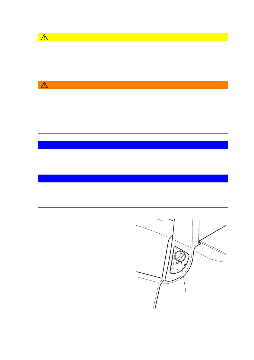
1.2 LPG system relief valve........................................................................... 47
2 Adding diesel ........................................................................................... 48
2.1 Fuelling .................................................................................................... 48
2.2 Fuelling with fuel containers .................................................................... 49
3 LPG containers........................................................................................ 50
3.1 LPG bottles.............................................................................................. 50
3.2 Liquid gas tank ........................................................................................ 53
4 Fuel level indicator................................................................................... 54
4.1 Display unit .............................................................................................. 54
4.2 Level indicator for LPG bottles (o) ........................................................... 54
E Operation ................................................................................ 55
1 Safety Regulations for the Operation of the Forklift Truck....................... 55
2 Displays and Controls.............................................................................. 57
2.1 Control panel with display unit ................................................................. 59
3 Preparing the Truck for Operation ........................................................... 62
3.1 Checks and operations to be performed before starting daily operation . 62
3.2 Entry and exit........................................................................................... 63
3.3 Trucks with reduced headroom X (o) ...................................................... 63
3.4 Setting up the operator position............................................................... 64
3.5 Seat Belt .................................................................................................. 68
4 Industrial Truck Operation ....................................................................... 69
4.1 Safety regulations for truck operation ...................................................... 69
4.2 Preparing the truck for operation ............................................................. 71
4.3 Parking the truck securely ....................................................................... 74
4.4 Emergency Disconnect............................................................................ 75
4.5 Travel....................................................................................................... 76
4.6 Steering ................................................................................................... 77
4.7 Brakes ..................................................................................................... 78
4.8 Adjusting the forks ................................................................................... 80
4.9 Replacing the forks.................................................................................. 81
4.10 Lifting, transporting and depositing loads ................................................ 82
4.11 Operating the lift mechanism and integrated attachments ...................... 84
4.12 Safety instructions for operating additional attachments ......................... 89
4.13 Operating additional attachments for the SOLO-PILOT .......................... 92
4.14 Fitting additional attachments.................................................................. 94
5 Towing trailers ......................................................................................... 96
6 Optional equipment ................................................................................. 98
6.1 Steel cab.................................................................................................. 98
6.2 Sliding windows ....................................................................................... 99
6.3 Panel door ............................................................................................... 100
6.4 Operator position extension..................................................................... 100
6.5 Backrest extension .................................................................................. 101
6.6 Heating and air conditioning system........................................................ 102
6.7 Removable load backrest ........................................................................ 104
6.8 Fire extinguisher ...................................................................................... 104
8
08.11 EN
Page 9

6.9 Rockinger coupling with hand lever or remote control............................. 105
6.10 Camera system ....................................................................................... 106
6.11 Optional equipment for working in areas with heavy accumulation of dust 107
6.12 Roof window wiper .................................................................................. 107
6.13 Tilt angle display...................................................................................... 108
6.14 Speed reduction ...................................................................................... 108
6.15 Reversing Block....................................................................................... 108
6.16 Direction switch mounted to the steering column .................................... 108
6.17 Temperature control system.................................................................... 109
7 Troubleshooting....................................................................................... 110
7.1 Troubleshooting....................................................................................... 110
7.2 Operating the truck without its own drive system .................................... 113
F Industrial Truck Maintenance .................................................. 117
1 Operational Safety and Environmental Protection................................... 117
2 Maintenance Safety Regulations............................................................. 118
3 Servicing and Inspection ......................................................................... 123
4 Maintenance checklist DFG..................................................................... 123
4.1 Owner ...................................................................................................... 123
4.2 Customer Service .................................................................................... 127
5 Maintenance checklist TFG ..................................................................... 135
5.1 Owner ...................................................................................................... 135
5.2 Customer Service .................................................................................... 139
6 Lubricants and Lubrication Schedule ...................................................... 148
6.1 Handling consumables safely .................................................................. 148
6.2 Lubrication Schedule ............................................................................... 150
6.3 Consumables........................................................................................... 151
7 Maintenance and repairs ......................................................................... 154
7.1 Preparing the truck for maintenance and repairs .................................... 154
7.2 Opening the rear panel ............................................................................ 154
7.3 Unlocking the engine bonnet ................................................................... 155
7.4 Checking the wheel attachments............................................................. 156
7.5 Hydraulic system ..................................................................................... 157
7.6 Engine maintenance ................................................................................ 160
7.7 Checking electrical fuses ......................................................................... 173
7.8 Starter battery.......................................................................................... 177
7.9 Exhaust system ....................................................................................... 178
7.10 Seat belt maintenance............................................................................. 179
7.11 Transmission ........................................................................................... 179
7.12 Brake ....................................................................................................... 180
7.13 Restoring the truck to service after maintenance and repairs ................. 181
8 Decommissioning the industrial truck ...................................................... 182
8.1 Prior to decommissioning ........................................................................ 183
8.2 During decommissioning ......................................................................... 183
8.3 Restoring the truck to service after decommissioning ............................. 184
9 Safety tests to be performed at intervals and after unusual incidents ..... 185
10 Final de-commissioning, disposal............................................................ 186
11 Human vibration measurement ............................................................... 186
08.11 EN
9
Page 10

10
08.11 EN
Page 11

A Correct Use and Application
1 General
The industrial truck described in the present operating instructions is designed for
lifting, lowering and transporting load units.
It must be used, operated and serviced in accordance with the present instructions.
Any other type of use is beyond the scope of application and can result in damage to
personnel, the industrial truck or property.
2 Correct application
NOTE
The maximum load and load distance are indicated on the load chart and must not be
exceeded.
The load must rest on the load handler or be lifted by an attachment approved by the
manufacturer.
The load must rest on the back of the fork carriage and centrally between the forks.
– Lifting and lowering of loads.
– Transporting lowered loads over short distances.
– Do not travel with a raised load (>30 cm).
– Do not carry or lift passengers.
– Do push or pull load units.
– Occasional towing of trailer loads.
– When towing trailer loads the load must be secured on the trailer.
– The permissible trailer load must not be exceeded.
08.11 EN
11
Page 12

3 Approved application conditions
DANGER!
Do not exceed the permissible surface and spot load limits on the travel routes.
At blind spots get a second person to assist.
The driver must ensure that the loading dock / ramp cannot move or come loose
during loading / unloading.
– Operation in industrial and commercial environments.
– Permissible temperature range -20 to 40°C.
– Operation only on secure, level surfaces with sufficient capacity.
– Operation only on routes that are visible and approved by the proprietor.
– Negotiating inclines up to a maximum of 15 %.
– Do not negotiate inclines crosswise or at an angle. Transporting loads downhill.
– Operation in partially public traffic.
WARNING!
Extreme conditions
XSpecial equipment and authorisation are required if the truck is to be constantly
used in extreme conditions, especially in dusty or corrosive atmospheres.
XThe truck is not authorised for use in areas at risk of explosion.
XIn adverse weather conditions (thunder, lightning) the industrial truck must not be
operated outside or in endangered areas.
12
08.11 EN
Page 13

4 Proprietor responsibilities
For the purposes of the present operating instructions the “proprietor” is defined as
any natural or legal person who either uses the industrial truck himself, or on whose
behalf it is used. In special cases (e.g. leasing or renting) the proprietor is considered
the person who, in accordance with existing contractual agreements between the
owner and user of the industrial truck, is charged with operational duties.
The proprietor must ensure that the industrial truck is used only for the purpose for
which it is intended and that there is no danger to life and limb of the user and third
parties. Furthermore, accident prevention regulations, safety regulations and
operating, servicing and repair guidelines must be followed. The proprietor must
ensure that all users have read and understood these operating instructions.
NOTE
Failure to comply with the operating instructions shall invalidate the warranty. The
same applies if improper work is carried out on the truck by the customer or third
parties without the permission of the manufacturer.
5 Adding attachments and/or accessories
Adding accessories
The mounting or installation of additional equipment which affects or enhances the
performance of the forklift truck requires the written permission of the manufacturer.
Local authority approval may also need to be obtained.
Local authority approval does not however constitute the manufacturer’s approval.
08.11 EN
13
Page 14

14
08.11 EN
Page 15
B Truck Description
1 Application
The DFG/TFG 316-435 is a four-wheel IC motor sit-down forklift truck. The DFG
series are diesel engine trucks, while the TFG series are fitted with a petrol engine for
LPG operation.
The DFG/TFG 316-435 is a cantilever counterbalanced truck which can lift, transport
and deposit loads using the load handler attached in front.
Closed bottom pallets can also be lifted.
The DFG/TFG 316-435 is equipped with a hydrodynamic drive. The left pedal is a
combination of crawl speed and brake pedal, and activates the rapid lift function
during slow travel. The middle pedal is a standard brake as well as emergency brake
pedal.
1.1 Truck models and rated capacity
The rated capacity depends on the model. The rated capacity can be derived from
the model description.
DFG316
DFG Model name
3Series
16 Rated capacity x 100 kg
The rated capacity does not generally match the permissible capacity. The capacity
can be found on the load chart attached to the rack.
08.11 EN
15
Page 16
2 Assemblies and Functional Description
2.1 Assembly Overview
1
12
14
Item Description Item Description
1 t Overhead guard 9 t Lift mechanism control
2 t Driver's seat 10 t Engine Cover
3 t Steering wheel 11 t Steer axle
4 t Control / display unit 12 t Trailer coupling
5 t Mast 13 t Counterweight
6 t Fork carriage 14 t LPG bottle (TFG only)
7 t Fork
8 t Drive
t = Standard equipment o = Optional equipment
13
2453
11
10
6
7
8
9
16
08.11 EN
Page 17

2.2 Functional Description
Chassis
The chassis, in conjunction with the counterweight, forms the supporting base
structure of the truck. It is used to support the main components.
The hydraulic oil reservoir is integrated on the right-hand side and the fuel tank for the
DFG series is on the left side in the chassis.
Operator position and overhead guard
The overhead guard (1) comes in a range of models and protects the driver from
falling objects and other external influences.
All the controls are ergonomically arranged. The steering column and driver's seat
can be adjusted individually.
The controls and warnings on the display unit (4) enable the system to be monitored
during operation, thereby ensuring a very high level of safety.
Steering
The steer cylinder of the hydrostatic steering is integrated in the steer axle (11) and
is controlled by the power steering. The steer axle is fully floating in the chassis to
ensure excellent grip even on non-level surfaces.
Wheels
All wheels are located within the truck geometry. A choice of pneumatic or
superelastic tyres are available.
Engine
High performance, water-cooled diesel and LPG engines with long useful lives and
low consumption and emission levels.
Electrical system
12 volt system with threephase alternator. A start block prevents malfunctions when
the truck is powered up. For diesel engines, a rapid pre-heat system is installed; LPG
motors have an electronic ignition system for rapid and trouble-free engine starting.
The key switch is used to stop the engine.
08.11 EN
17
Page 18

Drive system
A power shift gear with radiator and torque converter transfers the force to the drive
axle (8).
The travel direction switch on the left hydraulic control lever regulates forward/reverse
travel and the neutral position.
Brakes
The brake pedal actuates two drum brakes which are applied to the drive wheels. An
additional slow travel / brake pedal facilitates creep speed applications. The pedal
should not be used for normal braking purposes. Worn drum brakes are automatically
adjusted. The parking brake operates through mechanical actuation of the parking
brake lever on the drum brake via Bowden cables.
Hydraulic system
A multi-pilot valve allows for sensitive operation of the functions via the controls. A
speed-controlled hydraulic pump ensures a proportionate and efficient supply to the
hydraulic functions.
Mast
Two or three-stage masts, optionally with free lift function; narrow mast sections
ensure excellent visibility of the forks and attachments. Fork carriage and mast run
on permanently lubricated and hence maintenance-free support rollers.
Attachments
The trucks can be optionally fitted with mechanical and hydraulic attachments.
18
08.11 EN
Page 19

3 Technical Specifications
All technical details refer to standard trucks.
Values indicated with *) may vary, depending on the
types of equipment used (e.g. mast, cabin, tyres etc.).
Z Technical data specified in accordance with VDI 2198.
Technical modifications and additions reserved.
3.1 Performance data
DFG 316/320
Description DFG 316 DFG 320
Q
C Load centre distance 500 500 mm
Lift speed, with / without
pressure for attachments
1)
for vertical mast.
2)
The values shown represent the maximum gradeability to overcome short
differences in height and surface unevenness (surface edges). The truck must not
operate on inclines of more than 15%.
C a pa c i t y
where C = 500 mm)
Travel speed* with /
without load
load
Lowering speed with /
without load
Gradeability 2)*
with / without load
Acceleration* with /
without load to 15 m
Available working
Oil flow for attachments 45 45 l/min
1600 2000 kg
1)
18.3/19.1 18.0/18.8 km/h
0.61/0.62 0.60/0.62 m/s
0.55/0.49 0.57/0.49 m/s
23 20 %
5.2/4.6 5.4/4.8 s
160 160 bar
08.11 EN
19
Page 20

TFG 316/320
Description TFG 316 TFG 320
Q
C a pa c i t y
where C = 500 mm)
1600 2000 kg
1)
C Load centre distance 500 500 mm
Travel speed* with /
without load
Lift speed, with / without
load
Lowering speed with /
without load
Gradeability 2)*
with / without load
Acceleration* with /
without load to 15 m
Available working
pressure for attachments
18.7/19.5 18.5/19.3 km/h
0.61/0.63 0.60/0.63 m/s
0.55/0.49 0.57/0.49 m/s
25 22 %
5.1/4.7 5.2/4.5 s
160 160 bar
Oil flow for attachments 45 45 l/min
1)
for vertical mast.
2)
The values shown represent the maximum gradeability to overcome short
differences in height and surface unevenness (surface edges). The truck must not
operate on inclines of more than 15%.
20
08.11 EN
Page 21

DFG 425-435
Description DFG 425 DFG 430 DFG 435
Q
C ap a ci ty
(where C = 500 mm)
2500 3000 3500 kg
1)
C Load centre distance 500 500 500 mm
Travel speed* with /
without load
Lift speed, with / without
load
Lowering speed with /
without load
Gradeability 2)* with /
without load
Acceleration* with /
without load to 15 m
Available working pressure
for attachments
17/19 18/19 18/19 km/h
0.53/0.60 0.53/0.60 0.49/0.54 m/s
0.55/0.45 0.55/0.45 0.55/0.42 m/s
27 23 18 %
4.9/4.3 5.6/4.8 5.7/4.9 s
160 160 160 bar
Oil flow for attachments 60 60 60 l/min
TFG 425-435
Description TFG 425 TFG 430 TFG 435
Q
C ap ac it y
(where C = 500 mm)
2500 3000 3500 kg
1)
C Load centre distance 500 500 500 mm
Travel speed* with /
without load
Lift speed, with / without
load
Lowering speed with /
without load
Gradeability 2)* with /
without load
Acceleration* with /
without load to 15 m
Available working pressure
for attachments
17/19 18/19 18/19 km/h
0.50/0.60 0.45/0.60 0.41/0.53 m/s
0.55/0.45 0.55/0.45 0.55/0.42 m/s
27 23 19 %
5.4/4.7 6.1/5.1 6.3/5.4 s
160 160 160 bar
Oil flow for attachments 60 60 60 l/min
1)
for vertical mast.
2)
The values shown represent the maximum gradeability to overcome short
differences in height and surface unevenness (surface edges). The truck must not
operate on inclines of more than 15%.
08.11 EN
21
Page 22

3.2 Dimensions
DFG/TFG 316/320
Description VFG
DFG/TFG 316 DFG/TFG 320
a/2 Safety distance 100 100 mm
h1Mast height retracted* 2185 2185 mm
h2Free lift* 150 150 mm
h
Lift* 3300 3300 mm
3
Mast height extended* 3920 3920 mm
h
4
h6Overhead guard height* 2145 2145 mm
h
Seat height* 1049 1049 mm
7
Coupling height 380 380 mm
h
10
a Mast tilt, fwd.* 7 7 °
ß Mast tilt, back* 7 7 °
l1Length, including forks* 3386 3406 mm
l2Headlength* 2236 2256 mm
b1Overall width* 1080 1080 mm
s/e/l Fork dimensions* 40x100x1150 40x100x1150 mm
m1Ground clearance with
load below mast*
m2Ground clearance
centre wheelbase*
Fork carriage ISO 2328
class / type A, B
b3Fork carriage width 980 980 mm
Ast Working aisle width for
pallets 800 x 1200
longit.
Ast Working aisle width for
pallets 1000 x 1200
traverse
Wa Turning radius 2020 2042 mm
b13Smallest turning radius 560 560 mm
x Load distance* 398 398 mm
c Load centre of gravity 500 500 mm
y Wheelbase 1495 1495 mm
120 120 mm
130 130 mm
2 A 2 A mm
3818 3840 mm
3618 3640 mm
*) The data listed in the table corresponds to the standard version.
22
08.11 EN
Page 23

DFG / TFG 425-435
Description VFG
DFG/TFG 425 DFG/TFG 430 DFG/TFG 435
a/2 Safety distance 100 100 100 mm
h1Mast height retracted* 2280 2280 2215 mm
h2Free lift* 150 150 150 mm
h
Lift* 3300 3300 2900 mm
3
Mast height extended* 3910 3910 3670 mm
h
4
h6Overhead guard height* 2220 2250 2250 mm
h
Seat height* 1082 1112 1112 mm
7
Coupling height 380 380 380 mm
h
10
a Mast tilt, fwd.* 6 6 6 °
ß Mast tilt, back* 8 8 8 °
l1Length, including forks* 3690 3810 3945 mm
l2Headlength* 2540 2660 2795 mm
b1Overall width* 1174 1300 1300 mm
s/e/l Fork dimensions* 40x120x1150 45x125x1150 50x125x1150 mm
m1Ground clearance with
125 125 140 mm
load below mast*
m2Ground clearance
130 150 165 mm
centre wheelbase*
Fork carriage ISO 2328
2 A3 A3 Amm
class / type A, B
b3Fork carriage width 1120 1120 1120 mm
Ast Working aisle width for
4163 4285 4470 mm
pallets 800 x 1200
longit.
Ast Working aisle width for
3963 4085 4270 mm
pallets 1000 x 1200
traverse
Wa Turning radius 2290 2370 2550 mm
b13Smallest turning radius 725 725 750 mm
x Load distance* 473 515 520 mm
c Load centre of gravity 500 500 500 mm
y Wheelbase 1685 1685 1785 mm
*) The data listed in the table corresponds to the standard version.
08.11 EN
23
Page 24
βα
24
08.11 EN
Page 25

3.3 Weights
Z All dimensions in kg.
DFG/TFG 316/320
DFG 316 DFG 320 TFG 316 TFG 320
Truck weight* 2870 3280 2840 3250
Axle load w.o. load front /
rear*
Axle load with load front /
rear*
*) The data listed in the table corresponds to the standard version.
DFG 425/430/435
Truck weight* 4290 4730 5028
Axle load w.o. load front /
rear*
Axle load with load front /
rear*
*) The data listed in the table corresponds to the standard version.
TFG 425/430/435
Truck weight* 4190 4630 4928
Axle load w.o. load front /
rear*
Axle load with load front /
rear*
1340/1530 1360/1920 1330/1510 1350/1900
3940/530 4600/680 3930/520 4580/670
DFG 425 DFG 430 DFG 435
2050/2240 2078/2719 2028/3000
5990/800 6960/907 7530/1000
TFG 425 TFG 430 TFG 435
2010/2180 2038/2659 1988/2940
5950/740 6920/847 7490/940
*) The data listed in the table corresponds to the standard version.
08.11 EN
25
Page 26

3.4 Mast versions
Z All dimensions in mm
DFG/TFG 316/320
VDI 3596
Description
ZT
ZZ
DZ
Mast table
Lift h3
2900 150 1985 3520 440
3100 150 2085 3720 450
3300 150 2185 3920 465
3600 150 2335 4220 485
3800 150 2435 4420 500
4000 150 2535 4620 525
4500 150 2835 5120 565
5000 150 3085 5620 600
2900 1290 1940 3550 465
3100 1390 2040 3750 480
3300 1490 2140 3950 490
3600 1640 2290 4250 515
3800 1740 2390 4450 545
4000 1840 2490 4650 555
4500 2140 2790 5150 600
4200 1290 1940 4850 590
4350 1340 1990 5000 600
4500 1390 2040 5150 610
4800 1490 2140 5450 630
5000 1565 2215 5650 650
5500 1740 2390 6150 700
6000 1940 2590 6650 740
Free lift h2Height retracted
h1
H ei gh t
extended h4
Mast
weight
(kg)
Special trucks are not included in this overview.
26
08.11 EN
Page 27

DFG/TFG 425/430
VDI 3596
Description
ZT
ZZ
DZ
Mast table
Lift h3Free lift h
425/430
2
Retracted
height h
1
Extended
height h
4 425/430
Mast
weight (kg)
2900 150 2115 3510/3670 700
3100 150 2215 3710/3870 720
3300 150 2315 3910/4070 740
3500 150 2415 4110/4270 760
3700 150 2515 4310/4470 780
4000 150 2665 4610/4770 830
4300 150 2865 4910/5070 865
4500 150 2965 5110/5270 885
4700 150 3065 5310/5470 905
5000 150 3215 5610/5770 935
5500 150 3515 6110/6270 995
5800 150 3665 6410/6570 1025
6000 150 3765 6610/6770 1045
2900 1480/1380 2080 3500/3600 735
3100 1580/1480 2180 3700/3800 755
3300 1680/1580 2280 3900/4000 780
3500 1780/1680 2380 4100/4200 800
3700 1880/1780 2480 4300/4400 820
4000 2030/1930 2630 4600/4700 850
4300 2230/2130 2830 4900/5000 904
4500 2330/2230 2930 5100/5200 930
4400 1480/1380 2080 5000/5100 920
4700 1580/1480 2180 5300/5400 950
5000 1680/1580 2280 5600/5700 980
5500 1880/1780 2480 6100/6200 1040
6000 2080/1980 2680 6600/6700 1100
6500 2280/2180 2880 7100/7200 1175
7000 2480/2380 3080 7600/7700 1235
08.11 EN
27
Page 28

DFG/TFG 435
Mast table
VDI 3596
Description
Lift h3Free lift h2Retracted
height h
2900 150 2228 3683 700
3300 150 2428 4083 740
ZT
3800 150 2678 4583 810
4300 150 2978 5083 875
4800 150 3228 5583 920
5000 150 3328 5783 940
4200 1330 2093 4963 920
4500 1430 2193 5263 950
DZ
4800 1530 2293 5563 980
5300 1730 2493 6063 1040
5800 1930 2693 6563 1100
6300 2130 2893 7063 1180
Special trucks are not included in this overview.
Extended
1
height h
4
Mast
weight (kg)
28
08.11 EN
Page 29

3.5 Tyre type
NOTE
When replacing tyres/rims fitted at the factory, always use original spare parts or tyres
approved by the manufacturer. Otherwise the manufacturer's specification cannot be
guaranteed.
If you have any queries please contact the manufacturer's customer service
department.
DFG/TFG 316/320
Description DFG / TFG
316 320
SE* 6.50 - 10 6.50 - 10
Pneumatic* 6.50 - 10-14PR 6.50 - 10-14PR
Front tyres
Rear tyres
DFG/TFG 425/435
Front tyres
Rear tyres
Ty r e p re s su r e
bar
max 10.0 max 10.0
Torque NM 200 200
SE* 18x7-8 18x7-8
Pneumatic* 18x7-8 14PR 18 x 7-8-14PR
Ty r e p re s su r e
bar
max 9.0 max 9.0
Torque NM 200 200
Description DFG / TFG
425 430 435
SE* 7.0 - 12 28 x 9 - 15 250 x 15
Pneumatic* 7.0 - 12-16PR
Ty r e p re s su r e
bar
10 9 8,25
28 x 9 - 15-
14PR
Torque NM 380 380 380
SE* 6.50 x 10 6.50 x 10 6.50 x 10
Pneumatic*
Ty r e p re s su r e
bar
6.50 x 10¹⁴PR
10 10 10
6.50 x 10¹⁴PR
Torque NM 200 200 200
250 x 15-16PR
6.50 x 10¹⁴PR
*) The models listed in the table correspond to the standard version. Other tyres can
be used depending on the truck's equipment.
08.11 EN
29
Page 30

3.6 Engine Data
DFG 316/320
Description DFG 316 DFG 320
Cylinder/cubic capacity 4/2505 4/2505 cm³
Idle speed 680 680 rpm
Rated speed (without load) 2350 2350 rpm
Engine output 28 28 kW
Fuel consumption
60 VDI duty cycles/h
TFG 316/320
Description TFG 316 TFG 320
Cylinder/cubic capacity 4/2065 4/2065 cm³
Idle speed 850 850 rpm
Rated speed (without load) 2700 2700 rpm
Engine output 29 29 kW
Fuel consumption
60 VDI duty cycles/h
DFG 425-435
Description DFG 425 DFG 430 DFG 435
Cylinder/cubic capacity 4/3331 4/3331 4/3331 cm³
Idle speed 680 680 680 rpm
Rated speed (without load) 2350 2350 2350 rpm
Engine output 40 40 40 kW
Fuel consumption
60 VDI duty cycles/h
2,5 2,85 l/h [kg/h]
2,2 2,4 l/h [kg/h]
3,5 3,8 4,0 l/h [kg/h]
TFG 425-435
Description TFG 425 TFG 430 TFG 435
Cylinder/cubic capacity 4/2488 4/2488 4/2488 cm³
Idle speed 850 850 850 rpm
Rated speed (without load) 2700 2700 2700 rpm
Engine output 36 36 36 kW
Fuel consumption
3,6 3,9 4,1 l/h [kg/h]
60 VDI duty cycles/h
30
08.11 EN
Page 31

3.7 EN norms
Noise emission level
– DFG/TFG 425/430: 79 dB (A)*
– DFG/TFG 435: 79 dB(A)*
*+/- 3 dB(A) depending on the truck's equipment
in accordance with 12053 as harmonised with ISO 4871.
Z The noise emission level is calculated in accordance with standard procedures and
takes into account the noise level when travelling, lifting and when idle. The noise
level is measured at the level of the driver's ear.
Vibration
– DFG/TFG 425/430: 0,50 m/s²
– DFG/TFG 435: 0,73 m/s²
in accordance with EN 13059.
Z The vibration acceleration acting on the body in the operating position is, in
accordance with standard procedures, the linearly integrated, weighted
acceleration in the vertical direction. It is calculated when travelling over bumps at
constant speed. These recordings were taken on a single occasion and must not
be confused with the human vibrations of the "2002/44/EC/Vibrations" operator
directive. The manufacturer offers a special service to measure these human
vibrations, (see "Human vibration measurement" on page 186).
Electromagnetic compatibility (EMC)
The manufacturer confirms that the truck adheres to the limits for electromagnetic
emissions and resistance as well as the static electricity discharge test in accordance
with EN 12895 as well as the standardised instructions contained therein.
Z No changes to electric or electronic components or their arrangement may be
made without the written agreement of the manufacturer.
WARNING!
Medical equipment can be damaged by non-ionised radiation
Electrical equipment on the truck emitting non-ionised radiation (e.g. wireless data
transmission) can affect operators' medical equipment (pacemakers, hearing aids
etc.) and result in malfunctions. Consult with a doctor or the medical equipment
manufacturer to clarify whether it can be used near the industrial truck.
08.11 EN
31
Page 32

3.8 Conditions of use
Ambient temperature
– operating at -20 to 40°C
Z Special equipment and authorisation are required if the truck is to be constantly
used in conditions of extreme temperature or air humidity fluctuations.
3.9 Electrical requirements
The manufacturer certifies compliance with the requirements for the design and
manufacture of electrical equipment, according to EN 1175 "Industrial Truck Safety Electrical Requirements", provided the truck is used according to its purpose.
32
08.11 EN
Page 33
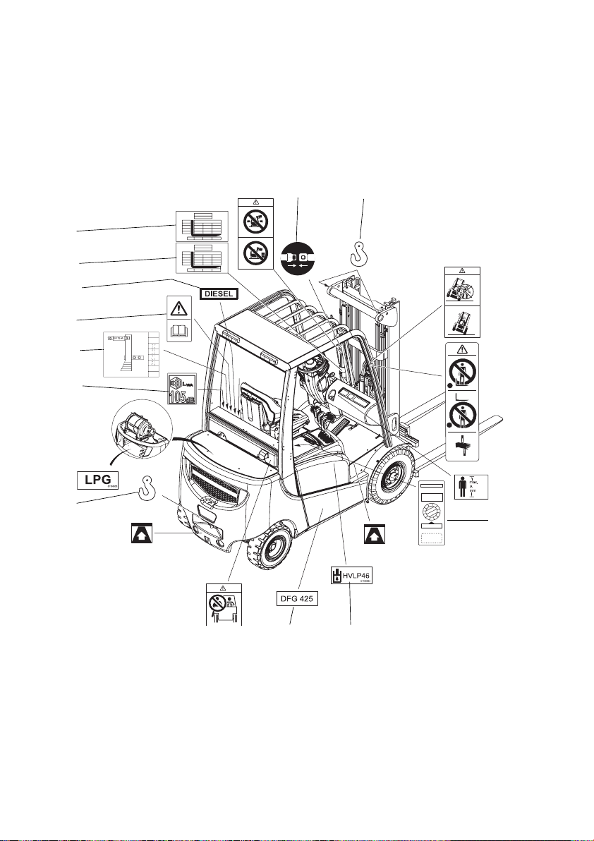
4 Identification points and data plates
Z Warnings and notices such as capacity charts, strap points and data plates must
be legible at all times. Replace if necessary.
18
19
20
20
16
22
23
26
29
17
24
15
16
29
21
21
25
27
1
1
2
1
1
0
9
0
1
8
200
2
7
3
6
5
4
28
32
31
30
08.11 EN
33
Page 34

Item Description
15 Wear seat belt notice
16 Strap points for crane lifting
17 Do not travel with raised load or mast tilted forward with a raised load
18 Capacity
19 Capacity with attachment
20 Fuel
21 Tipover hazard
22 Read operating instructions
23 Jump start connection
24 Truck data plate; under the engine cover (not shown)
25 Do not stand on load handler / Do not stand under load handler / Risk of
trapping when mast extended
26 Noise level
27 Max. body size (o)
28 Test plaque (o)
29 Jack contact points
30 Hydraulic oil specification
31 Model description
32 Do not carry passengers warning
Serial number, engraved in chassis below the engine cover
34
08.11 EN
Page 35
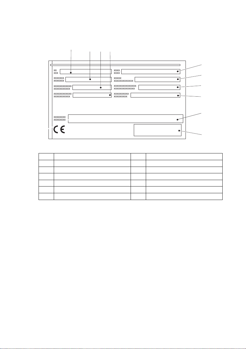
4.1 Data plate
Item Description Item Description
33 Type 38 Year of manufacture
34 Serial number 39 Load centre (mm)
35 Rated capacity (kg) 36 Output
36 Output 41 Manufacturer
40 Net weight in kg 42 Manufacturer’s logo
37 Option
33 34 3635
37
38
39
40
41
42
Z For queries regarding the truck or ordering spare parts always quote the truck serial
number (34).
08.11 EN
35
Page 36

4.2 Truck capacity plate
CAUTION!
Accident risk from fork replacement
If you replace the forks with ones that differ from the originals, the capacity will
change.
XWhen replacing the forks you must attach an additional capacity plate to the truck.
XTrucks supplied without forks are given a capacity plate for standard forks (length:
1150 mm).
The capacity plate (18) gives the capacity (Q in kg) of the truck for a vertical mast.
The maximum capacity is shown as a table with a given load centre of gravity D (in
mm) and the required lift height H (in mm).
The capacity plate (18) of the truck indicates the truck's capacity with the forks as
originally supplied.
Example of how to calculate the maximum capacity:
h3 (mm)
4250
3600
2900
D (mm) 500 600 700
850
1105
1250
Q (kg)
850
1105
1250
600
850
850
For a load cente of gravity D of 600 mm and a maximum lift height h3 of 3600 mm the
maximum capacity is Q 1105 kg.
Lift height restriction
The arrow shape markings (43 and 44)
on the inner and outer masts show the
43 44
driver when the prescribed lift limits
have been reached.
36
08.11 EN
Page 37

4.3 Attachment capacity plate
The attachment capacity plate is next to the truck's capacity plate and gives the
truck's capacity Q (in kg) in conjunction with the respective attachment. The serial
number for the attachment indicated on the capacity plate must match the data plate
of the attachment.
Z For loads with a centre of gravity greater than 500 mm, the capacities are reduced
by the difference of the altered centre of gravity.
5 Stability
The truck's stability has been tested according to latest technological standards.
These take into account the dynamic and static tipover forces that can occur if used
correctly.
Stability can also be affected by the following factors:
– Tyre type
–Mast
– Attachment
– Transported load (size, weight and centre of gravity)
WARNING!
Loss of stability can cause accidents
Changing the components can alter the stability.
08.11 EN
37
Page 38

38
08.11 EN
Page 39
C Transport and Commissioning
1 Transport
Transport can be carried out in two different ways, depending on the height of the
mast and the local conditions.
– Vertically, with the mast assembled (for low heights)
– Vertically, with the mast dismantled (for large heights), all mechanical connections
and hydraulic lines between the basic truck and the mast separated.
2 Truck laden
2.1 Centre of gravity of the truck
WARNING!
Altering the centre of gravity can be hazardous
The overall centre of gravity can vary depending on the truck's equipment (especially
the mast version).
XFor masts with a low height the centre of gravity will move towards the
counterweight.
XFor masts with a greater height the centre of gravity will move towards the centre
of the truck.
The picture shows the approximate centre of
gravity location.
08.11 EN
39
Page 40
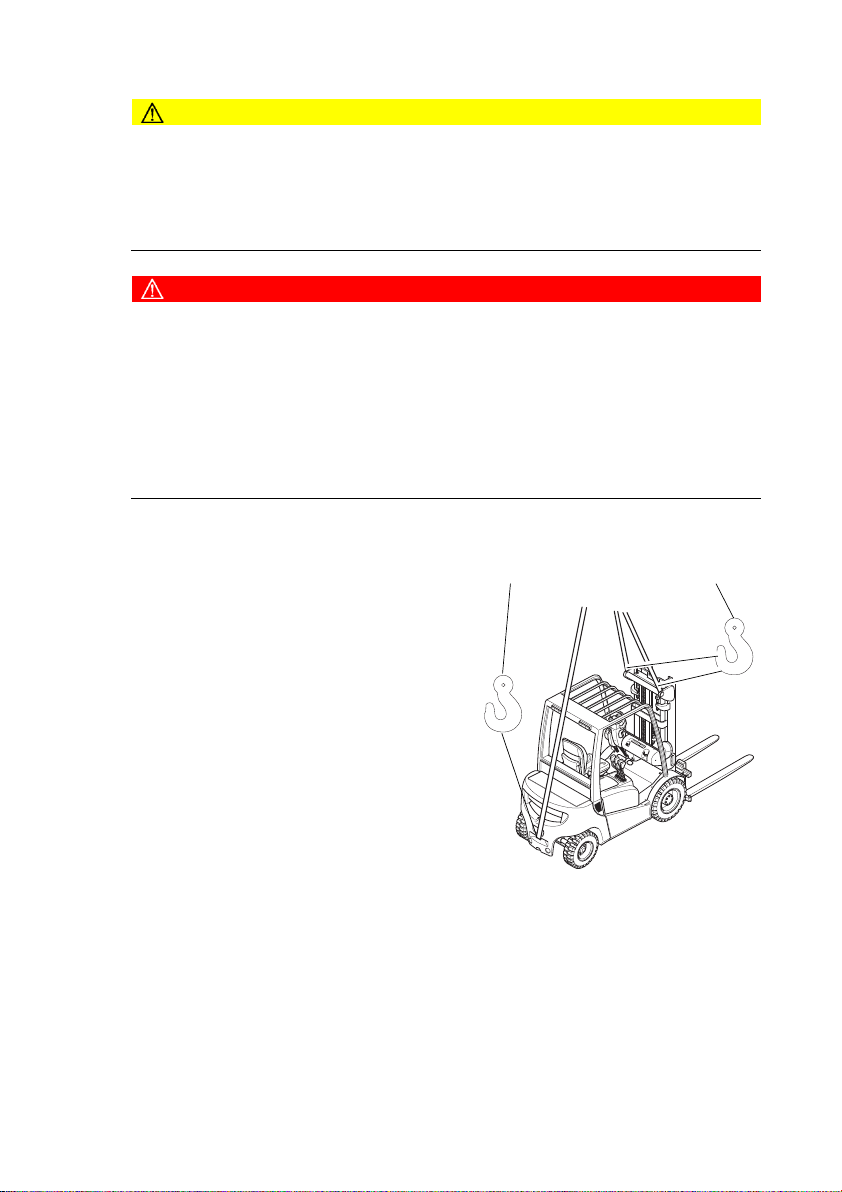
2.2 Lifting the truck by crane
CAUTION!
The mast can get damaged
XLoading by crane is only intended for the initial transport before the truck is used
for the first time.
XLoading must be carried out by specially trained staff in accordance with
recommendations contained in Guidelines VDI 2700 and VDI 2703
DANGER!
Crane slings can tear, resulting in accidents
XOnly use crane lifting gear with sufficient capacity.
XLoading weight = Net weight of truck (+ battery weight for electric trucks).
XThe mast must be tilted back fully.
XThe crane lifting gear on the mast must have a minimum clear length of 2 m.
XCrane slings should be fastened in such a way that they do not come into contact
with any attachments or the overhead guard when lifting.
XDo not stand under a swaying load.
Z Truck net weight: (see "Data plate" on page 35).
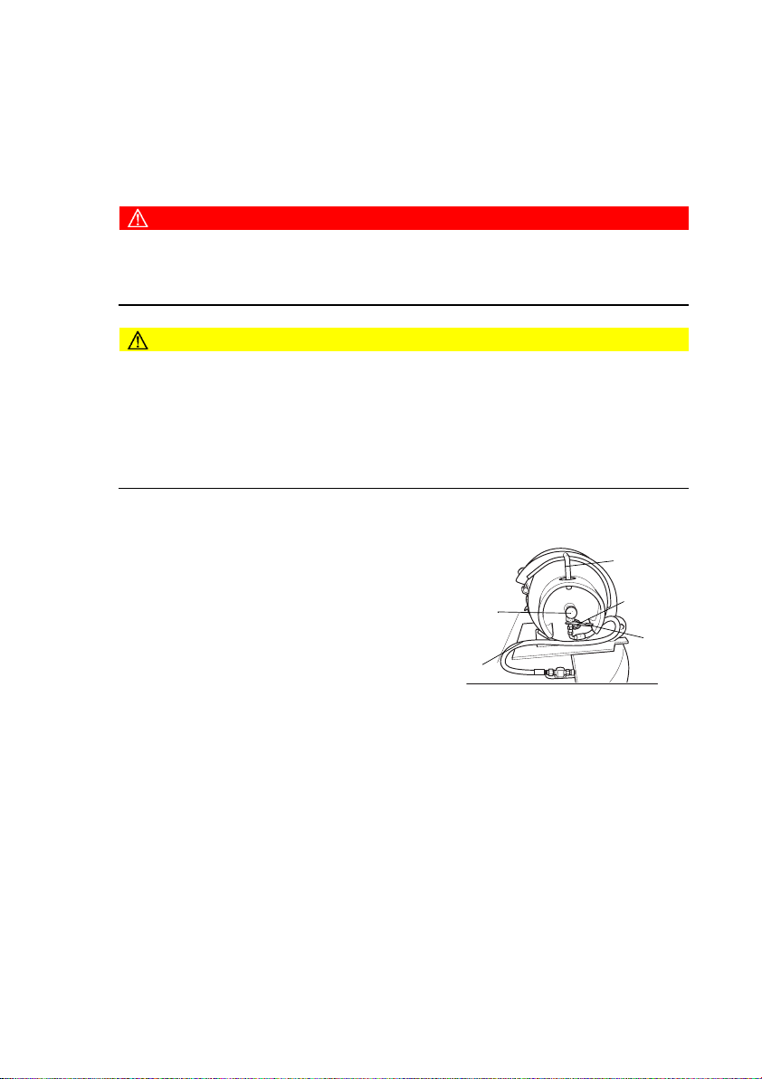
Lifting the truck by crane
Requirements
– Park the truck securely, (see "Parking the
truck securely" on page 74).
Procedure
• Fasten the crane slings securely to the
attachment points (46) and (45).
• Raise and load the truck.
• Lower and deposit the truck carefully ((see
"Parking the truck securely" on page 74)).
• Secure the truck with wedges to prevent it
from rolling away.
This concludes the loading by crane.
40
45 46
08.11 EN
Page 41

2.3 Loading with another industrial truck
WARNING!
The truck can be damaged
The truck to be loaded can get damaged when loading with another industrial truck.
XOnly trained specialist personnel should load the truck.
XUse only trucks with sufficient capacity for loading.
XOnly for loading and unloading.
XThe forks of the second industrial truck must be sufficiently long
XTransporting over long distances prohibited.
Loading the truck with a second industrial truck
Requirements
– Park the truck securely, (see "Parking the truck securely" on page 74).
Procedure
• Raise the truck with the forks at the side between the axles.
• Raise the truck slightly and make sure it is securely positioned on the forks. If
necessary adjust or secure the forks with stops.
• Carefully load/unload the truck, (see "Lifting, transporting and depositing loads" on
page 82).
• Lower the truck slowly onto the ground and prevent it from rolling away.
The truck is now loaded.
08.11 EN
41
Page 42

3 Securing the truck during transport
WARNING!
Accidental movement during transport
Improper fastening of the truck and mast during transport can result in serious
accidents.
XLoading must be carried out by specially trained staff in accordance with
recommendations contained in Guidelines VDI 2700 and VDI 2703 In each case
correct measurements must be made and appropriate safety measures adopted.
XThe truck must be securely fastened when transported on a lorry or a trailer.
XThe loading area must have clamp rings and a wooden floor to secure the retaining
wedges.
XUse wedges to prevent the truck from moving.
XUse only tensioning belts or tie-down straps or with sufficient strength.
Securing with a mast Securing without a mast
46
12
Securing the truck for transport
Requirements
– Position the truck securely on a lorry or trailer, (see "Parking the truck securely" on
page 74).
Tools and Material Required
– 2 tensioning belts with tensioner
– Retaining wedges.
Procedure
• Secure the truck with the tensioning belt (47) at the top cross member of the mast
(5) and the trailer coupling (12) or over the mud guard (48) and the trailer coupling
(12).
• Tighten the tensioning belt (47) with the tensioner (47).
The truck is now secured for transport.
47
47
47
48
47
42
08.11 EN
Page 43

4 Using the Truck for the First Time
Safety Instructions for Assembly and Commissioning
WARNING!
Accident risk from incorrect assembly
The assembly of the truck at the application site, commissioning and driver training
must only be performed by the manufacturer's customer service representatives who
have been specially trained for these tasks.
XThe hydraulic lines may only be connected to the basic truck / mast interface when
the mast has been properly assembled.
XOnly then can the truck be started.
XIf several trucks have been delivered, make sure that the serial numbers of the load
handlers, masts and basic trucks always match.
Preparing the truck for operation after delivery or transport
Procedure
• Check the equipment is complete.
• Check the engine oil level.
• Check the hydraulic oil level. Check the transmission oil level (only on trucks with
hydrodynamic drives).
• Check the brake fluid level (only on trucks with hydrodynamic drives).
• Test the battery connections.
• Check the battery acid level (not for maintenance-free batteries).
The truck can now be started, (see "Preparing the Truck for Operation" on page 62).
08.11 EN
43
Page 44

44
08.11 EN
Page 45

D Fuelling the Truck
1 General
1.1 Safety regulations for handling diesel fuel and LPG
WARNING!
An unsecured truck can cause accidents
The truck can suddenly start to move.
XBefore filling up or replacing the LPG bottle, park the truck securely, Siehe “Parking
the truck securely” auf Seite 74.
WARNING!
Accident risk from ignition
XFuels and liquefied petroleum gas can ignite.
XSmoking, naked flames and other ignition sources are strictly prohibited in the
immediate vicinity when handling fuels and LPG.
XLabels indicating the hazard are must be positioned where they are clearly visible.
XDo not store flammable materials in this area.
XPowder fire extinguisher must be provided within easy reach of the filling area.
XUse only category A, B or C type powder fire extinguishers to fight LPG fires.
XBring any unsealed LPG bottles immediately outside, attach visible markings and
notify the supplier.
Storage and Transport
The diesel and LPG storage and transport devices must comply with statutory
requirements.
If there is no filling point available, the fuel must be stored and transported in clean,
approved containers.
The contents must be clearly indicated on the container.
08.11 EN
45
Page 46

NOTE
Fuel can cause environmental damage
XBind any spilled diesel fuel with suitable methods.
XThen dispose of the diesel and fuel filter in accordance with environmental
regulations.
Fuel filling and LPG bottle replacement personnel
Personnel filling the trucks or replacing LPG bottles must have sufficient knowledge
of the nature of fuels to ensure safe operation.
CAUTION!
Liquid gas can cause frostbite
XLiquid gas produces frostbite when it comes into contact with bare skin.
XAvoid direct contact with the skin.
XWear gloves.
Filling up LPG containers
LPG containers remain attached to the truck and are filled up at LPG stations. Always
follow the instructions of the tank system and LPG container manufacturer as well as
statutory and local regulations when filling up.
NOTE
Instructions for the safe operation of LPG systems
XAll maintenance and repair work on LPG systems and containers should be carried
out by qualified personnel who have been trained to work on LPG systems.
XThe owner must comply with all legal requirements, technical standards and health
and safety regulations applicable to liquid gas.
XBefore starting work, the driver must check that all accessible components of the
LPG system are in good working order, in accordance with the regulations of the
country of use.
XDo not operate the truck if there is any damage, corrosion, wear or degradation to
individual components of the LPG system.
46
08.11 EN
Page 47

1.2 LPG system relief valve
LPG powered trucks are fitted with a relief
valve. This is located on the rear cover next
to the gas bottle.
– In the event of a fault the pressure in the
gas system is restricted to a maximum
level. The relief valve is fitted with a
plastic cover (45).
– When the valve is activated the plastic
cover comes off, thereby clearly
indicating a fault in the gas system.
– In this event the truck must not be operated.
– The gas system must be check by suitably qualified and trained personnel.
– The user must check that the plastic cover is present each time he uses the truck.
DANGER!
Danger from escaping liquid gas.
Liquid gas can escape from faulty gas hoses.
XUse only gas bottles with an integrated line break safety valve.
XThe gas bottle connection is also fitted with a line break safety valve which prevents
the gas from escaping accidentally during operation.
XWhen replacing, always use a gas bottle connection with an integrated line break
safety valve.
49
08.11 EN
47
Page 48
2 Adding diesel
CAUTION!
Air in the fuel system will result in malfunctions.
XNever allow the fuel tank to run dry.
2.1 Fuelling
WARNING!
Diesel fuel can be hazardous
XDiesel fuel can cause irritation if it comes into contact with the skin. Rinse any
affected areas thoroughly.
XIf it comes into contact with the eyes rinse them immediately with flowing water and
call for a doctor.
XWear safety gloves when handling diesel fuels.
NOTE
Fuelling must always be performed in designated areas by trained and
authorised personnel.
NOTE
XCapacity: DFG 316/320s = 48 l.
Capacity: DFG 425-435 = 58 l.
XUse only diesel in accordance with DIN 590 with a cetane rating above 51.
2.1.1 Fuelling the tank system
Procedure
• Park the truck securely before fuelling,
(see "Parking the truck securely" on
page 74)
• Unscrew the tank cap (50).
• Insert the tap into the open tank filler
neck.
• Add the fuel.
• Do not overfill the tank.
• Tighten the cap (50) back on after
fuelling.
Fuelling is now complete.
48
50
08.11 EN
Page 49

2.2 Fuelling with fuel containers
Procedure
• Unscrew the tank cap (50) and open the
fuel container.
• Fit the outlet pipe onto the fuel
container.
• Insert the outlet pipe into the open tank
filler neck.
• Make sure the fuel container and outlet
pipe are connected tightly to each
other.
• Raise the fuel container carefully and
slowly add the diesel.
• Do not overfill the tank.
• Tighten the cap (50) back on after
fuelling.
Fuelling is now complete.
50
08.11 EN
49
Page 50
3 LPG containers
Z Only use liquid gas that complies with DIN 51622 or comparable national
regulations.
3.1 LPG bottles
DANGER!
Risk of explosion
XThe LPG bottle must only be replaced at designated areas by trained and
authorised personnel.
CAUTION!
Using unsuitable LPG bottles can cause accidents.
XUse only approved LPG bottles.
XThe LPG bottle must always rest on an engaged bottle holder so that the hose
connection of the shutoff valve is facing vertically down.
XFor bottle types of other countries note the national regulations.
XNote the indications and markings on the LPG bottle.
3.1.1 Using an LPG bottle
Replace the LPG bottle
Procedure
• Park the truck securely before replacing the
LPG bottle, (see "Parking the truck
securely" on page 74)
• Close the shut-off valves (53) securely.
• Start the motor and allow the LPG system to
run empty in neutral.
50
55
53
51
52
54
08.11 EN
Page 51

Remove the LPG bottle
CAUTION!
The connection has a left thread
51
Procedure
• Unscrew the union nut (52) while holding
against the handle (54).
57
58
• Remove the hose (55) and immediately
screw the valve cap onto the empty LPG
bottle.
• Remove the stop bolt (56) and rotate the
LPG bottle and bracket around the handle
(51).
• Fold back the lever of the toggle-type
fastener (59) and remove the tensioning
pivot.
• Remove the tensioning belt.
• Carefully remove the LPG bottle from the
bracket (58) and place it down securely.
Inserting a new LPG bottle
Procedure
• Insert the LPG bottle into the bracket (58)
53
• Centre the handle (51) in the hole (57).
• Align the hose connection upwards.
• Fit the tensioning belt around the LPG bottle
55
again and tension it with the toggle-type
fastener (59).
• Fit the tensioning pivot and tension the belt
with the toggle-type fastener (59).
• Rotate the LPG bottle and the bracket around the handle (51).
• Insert the stop bolt (56).
• Unscrew the valve cap.
• Fit the hose (55) in accordance with instructions.
• Carefully open the shut-off valve (53).
• Check the hose connection for leaks using a foam-forming agent.
The replacement is now complete.
56
59
51
52
54
08.11 EN
51
Page 52

3.1.2 Operating with two LPG bottles
WARNING!
Visibility is restricted when the truck reverses.
XWhen using two LPG bottles the truck must be fitted with a functional camera
system for reversing.
XExternal mirrors must also be fitted on either side of the truck.
Operating the twin bottle system
NOTE
Use the additional valve (60) on the
bracket (58) to change between gas
supply. You can tell which bottle is
supplying the gas by the gas hose
connection on the valve (55) and the
routing towards the LPG bottles (e.g.
RH side of toggle valve = up, LH side of
toggle valve = down).
Procedure
• Use the lever (61) to change between the top
and bottom LPG bottles.
Replacing the LPG bottles
Procedure
• (see "Using an LPG bottle" on page 50)
55
55
58
60
61
Z Replace an empty LPG bottle at the earliest opportunity with a full one.
Switching off the gas supply
Procedure
• Close both shutoff valves on the gas bottles to interrupt the supply of gas.
52
08.11 EN
Page 53

3.2 Liquid gas tank
Refillable liquid gas tanks contain a dispensing valve (66), a filling stop valve (64), a
relief valve (65) and a display (62).
Filling refillable liquid gas tanks (optional
equipment).
Requirements
– Note all guidelines and regulations
concerning the filling of LPG bottles on the
LPG pump.
Procedure
• Close the dispensing valve (66).
• Unscrew the cap (63) of the filling stop valve
(64).
• Screw the filling connection of the liquid gas
pump onto the filling stop valve (64).
66
65
64
62
63
Z Fuelling automatically ends when the tank's
capacity has been reached.
• After fuelling, unscrew the filling connection and screw the cap (63) of the filling
stop valve (64) back on.
08.11 EN
53
Page 54

4 Fuel level indicator
4.1 Display unit
The level indicator (68) shows the capacity of
the tank (only for DFG).
If the indicator (68) reaches the red zone, fill
the tank. This is also displayed by the spare
indicator (67).
4.2 Level indicator for LPG bottles (o)
When the level indicator for LPG bottles (69)
is lit (o), this indicates that the LPG bottle is
empty.
The remaining travel time will be 8 - 12
minutes, depending on the application and
ambient conditions.
Z Fluctuations in the liquid gas level caused
by the travel mode can cause the level
indicator to light up briefly. Only a
permanently lit level indicator means that
the LPG bottle is almost empty.
68
67
DFG
69
TFG
54
08.11 EN
Page 55

E Operation
1 Safety Regulations for the Operation of the
Forklift Truck
Driver authorisation
The truck may only be used by suitably trained personnel, who have demonstrated to
the proprietor or his representative that they can drive and handle loads and have
been authorised to operate the truck by the proprietor or his representative.
Driver’s rights, obligations and responsibilities
The driver must be informed of his duties and responsibilities and be instructed in the
operation of the truck and shall be familiar with the operating instructions. The driver
shall be afforded all due rights. Safety shoes must be worn for pedestrian operated
trucks.
Unauthorised use of truck
The driver is responsible for the truck during the time it is in use. The driver must
prevent unauthorised persons from driving or operating the truck. Do not carry
passengers or lift other people.
Damage and faults
The supervisor must be immediately informed of any damage or faults to the truck or
attachment. Trucks which are unsafe for operation (e.g. wheel or brake problems)
must not be used until they have been rectified.
Repairs
The driver must not carry out any repairs or alterations to the truck without the
necessary training and authorisation to do so. The driver must never disable or adjust
safety mechanisms or switches.
08.11 EN
55
Page 56

Hazardous area
WARNING!
Risk of accidents / injury in the hazardous area of the truck
The hazardous area is defined as the area in which a person is at risk due to truck
movement, lifting operations, the load handler (e.g. forks or attachments) or the load
itself. This also includes areas which can be reached by falling loads or lowering
operating equipment.
XInstruct unauthorised people to leave the hazardous area.
XGive a warning signal with plenty of time for people to leave.
XIf unauthorised personnel are still within the hazardous area stop the truck
immediately.
DANGER!
Accident risk
XThe driver must remain within the protected area of the overhead guard while the
truck is being operated.
Safety devices and warning labels
Safety devices, warning signs ((see "Identification points and data plates" on
page 33)) and warning instructions in the present operating instructions must be
strictly observed.
CAUTION!
Reduced headroom can cause injuries
XTrucks with reduced headroom are equipped with a warning label within the driver's
line of sight. The max. recommended body size indicated on this sign must be
observed.
XThe headroom is also reduced when you wear a protective helmet.
56
08.11 EN
Page 57

2 Displays and Controls
70 71
72 73 74
75
0
I
II
76
77
78
79
80
08.11 EN
57
Page 58

Item Control /
Function
Display
70 Direction switch t Selects travel direction / neutral position
71 Horn t Activates an audible warning.
Slow travel / brake pedal t 1. zone: controls slow travel.
72
2. zone: applies service brake.
73 Parking brake lever t Applies / releases parking brake
74 Steering wheel t Steering the Industrial truck.
72 Steering column
t Adjusts the steering column tilt.
adjusting lever
76 Key switch t Switches power supply on and off.
Starts and stops the engine.
O - All main circuits are cut out and the key
can be removed.
I - Controls and instruments are switched on.
Engine preheating (diesel only).
II -Starting the motor (automatically returns
to the I position).
77 Options switch t Options
78 Brake pedal t The truck brakes to a halt immediately when
applied.
79 Accelerator pedal t Infinite travel speed control.
80 SOLOPILOT t Operates the following functions:
– Load handler lift/lower
– Mast forward / reverse tilt
– Sideshift left / right (o)
– Auxiliary hydraulics (o)
t= Series equipment o= Optional equipment
58
08.11 EN
Page 59

2.1 Control panel with display unit
The control panel display unit shows the operating data, the battery charge, the
service hours and error details and information. Pictograms in the left top section of
the control panel act as warning indicators.
88
81
86
85
67
94
82
89
9068 91 92 93
Item Control /
Display
67 DFG fuel indicator t
TFG with gas tank
68
Fuel display (DFG)
83
81
87
89
90
82
88
92 93
86
85
67
Function
Graphic illustration of the fuel supply.
t
t Indicates how much fuel is left in the
tank.
94
81 Transmission oil
temperature indicator
t When lit, indicates that the
transmission oil temperature is too
high.
82 Engine oil pressure
display
t When lit, indicates that the engine oil
pressure is too low.
83 Soot filter indicator t Indicates that the soot filter is
contaminated.
08.11 EN
59
Page 60

Item Control /
Display
85 Brake fluid indicator t When lit, indicates the brake fluid level
Function
is too low.
86 Parking brake
87 Diesel filter indicator t Lights up to indicate that the diesel
88 Charge current
89 Air filter control o Lights up when the air filter is clogged
90 Indicator lamp neutral t When lit, indicates that the travel
91 Pre-heat indicator
92
93 Time / service hours
94 Coolant temperature
warning indicator
indicator
lamp
Direction indicator
lamp
display
display
t Parking brake activated
– Truck operational, parking brake
applied
filter is clogged.
t Battery not charging.
direction switch is in neutral.
t Engine is preheated (DFG only)
o Shows the indicator status (right/left).
t Indicates the time or number of
operating hours in service.
t Indicates the coolant temperature.
t= Series equipment o= Optional equipment
Z Troubleshooting (see "Troubleshooting" on page 110).
60
08.11 EN
Page 61

2.1.1 Instrument panel switches (o)
Display Function
Front work lights Switches front work lights on and off.
Rear work lights Switches rear work lights on and off.
Beacon Switches the beacon on and off.
Rear windscreen
wiper
Warning light Switches warning light on and off.
Light switch Switches the light switch on and off.
Wiper Switches the wipers on and off.
Front windscreen
washing system
Fan Switches the fan on and off.
Rear windscreen
wiper
Roof window wiper Switches roof window wiper on and off.
WIPER
Work lights on mast Switches work lights on mast on and off.
Rear windscreen
heating
Switches rear windscreen wiper on and
off.
Switches the windscreen washing system
on and off.
Switches rear windscreen wiper on and
off.
Switches rear windscreen heating on and
off.
Z The arrangement of switches is variable and not assigned to any fixed assembly
location.
08.11 EN
61
Page 62
3 Preparing the Truck for Operation
3.1 Checks and operations to be performed before starting daily
operation
WARNING!
Damage and other truck or attachment (special equipment) defects can result
in accidents.
If damage or other truck or attachment (special equipment) defects are discovered
during the following checks, the truck must be taken out of service until it has been
repaired.
XReport any defects immediately to your supervisor.
XTag out and decommission a faulty lift truck.
XOnly return the truck to service when you have identified and rectified the fault.
CAUTION!
Checking the accelerator pedal
XThe accelerator pedal should only be
checked when the parking brake is
applied and the engine is idle.
Checks after daily operation
Procedure
• Visually inspect the entire truck (in particular wheels, wheel bolts and load handler)
for damage.
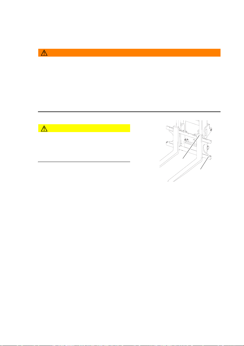
• Check the fork stop (95) and fork retainer (96).
• Visually inspect the hydraulic system in the visible area for damage and leaks.
• Check the driver’s seat has been adjusted to the correct position.
• Test the horn and reversing buzzer (o) where applicable.
• Check that the load chart and warning labels are legible.
• Test the controls and displays.
• Test the steering.
• Make sure the load chains are evenly tensioned.
• Test the seat belt. (The belt should block if extracted suddenly.)
• Test the seat switch. When the driver’s seat is vacated it should not be possible to
activate the working hydraulics.
• Test the restraint system (o),
• Test the lift/lower, tilt and if applicable the attachment hydraulic control functions.
• Check the accelerator pedal can move freely by pressing it several times.
• Test the service and parking brakes: Approach carefully and test the effectiveness
of the brake pedal.
• Check the fuel supply.
• Check the fluid level of the windscreen washing system (o), (see "Adding window
washer system fluid" on page 172).
• Check the gas system is working correctly, (see "LPG containers" on page 50)
62
95
96
08.11 EN
Page 63

3.2 Entry and exit
Procedure
• Open the cab door (o)
• To enter and exit the cab, hold onto the
handle (97).
Z An additional step is provided for the driver position extension (o)
3.3 Trucks with reduced headroom X (o)
WARNING!
An unsuitable workplace can damage
your health
Failure to observe the recommended
body size can cause stress and endanger
the driver and may lead to lasting ill health
due to an unhealthy posture and
excessive strain on the driver.
XThe owner must ensure that truck
operators do not exceed the maximum
body size indicated.
XThe owner must check that the drivers
can sit in a normal and upright position
without having to strain.
97
08.11 EN
63
Page 64

3.4 Setting up the operator position
WARNING!
Accident risk
XDo not adjust the driver’s seat while travelling.
Procedure
• Before starting to travel, adjust the driver’s seat, steering column and armrest (if
necessary) so that all the controls are within reach and can be applied without
having to strain.
• Adjust the visibility aid equipment (mirrors, camera systems etc.) so that the
working environment can be clearly seen.
3.4.1 Adjusting the driver’s seat
WARNING!
Risk of accidents and damage to health
An incorrectly adjusted driver’s seat can result in accidents and damage to health.
XDo not adjust the driver’s seat while travelling.
XThe driver’s seat should lock in position after adjustment.
XCheck and adjust the individual driver’s seat setting before starting to use the truck.
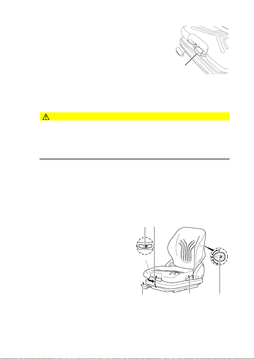
XHold the weight setting lever (98) only by the recess, do not reach through
underneath the lever.
64
08.11 EN
Page 65

Adjusting the driver's weight
NOTE
To achieve optimal seat cushioning the
driver’s seat must be set to the driver’s
weight.
Set the driver's weight when the seat is
occupied.
Procedure
• Fold out the weight adjustment lever
(98) as far as it will go in the arrow
direction
• Move the weight adjustment lever (98)
up and down to set the seat to a higher
weight.
• Move the weight adjustment lever (98) up and down to set the seat to a lower
weight.
99
98
101100
102
Z The driver's weight is correct when the arrow is in the middle of the display window
(99). The minimum or maximum weight setting is reached when you can feel a
return stroke on the lever.
• After setting the weight, move the lever (98) back in full.
The driver’s weight is now set.
Adjusting the backrest
Procedure
• Sit on the driver’s seat.
• Pull the lever (101) to adjust the backrest.
• Adjust the backrest tilt.
• Release the lever (101) again. The backrest is locked.
The backrest is now set.
Z Hold the weight setting lever (98) only by the recess, never reach through
underneath the lever.
08.11 EN
65
Page 66
Driver’s seat with pneumatic weight adjustment
(MSG 75) (
o
)
Procedure
• Pull the weight adjustment lever (98) up to set the seat
to a higher weight.
• Push the weight adjustment lever (98) down to set the
98
seat to a lower weight.
The driver's weight is correct when the arrow is in the middle of the display window
(99).
Adjusting the seat position
CAUTION!
An unsecured driver's seat can cause injury
An unsecured driver's seat can slide out of its guide during travel, resulting in
accidents.
XThe driver's seat must be locked in position.
XDo not adjust the driver’s seat while travelling.
Procedure
• Sit on the driver’s seat.
• Pull up the driver’s seat locking lever100 in the direction of the arrow.
• Push the driver’s seat forwards or backwards to the desired position
• Engage the driver’s seat locking lever (100) in position.
The seat position is now correctly set.
Adjusting the lumbar vertebrae
o
support (
)
Procedure
• Turn the hand wheel (102) to the
required position.
Position 0 = no warping in lumbar
vertebrae area.
Position 1 = increasing warping in
upper lumbar vertebrae area.
Position 2 = increasing warping in lower
lumbar vertebrae area.
The lumbar vertebrae support is now set.
66
99
98
101100
102
08.11 EN
Page 67
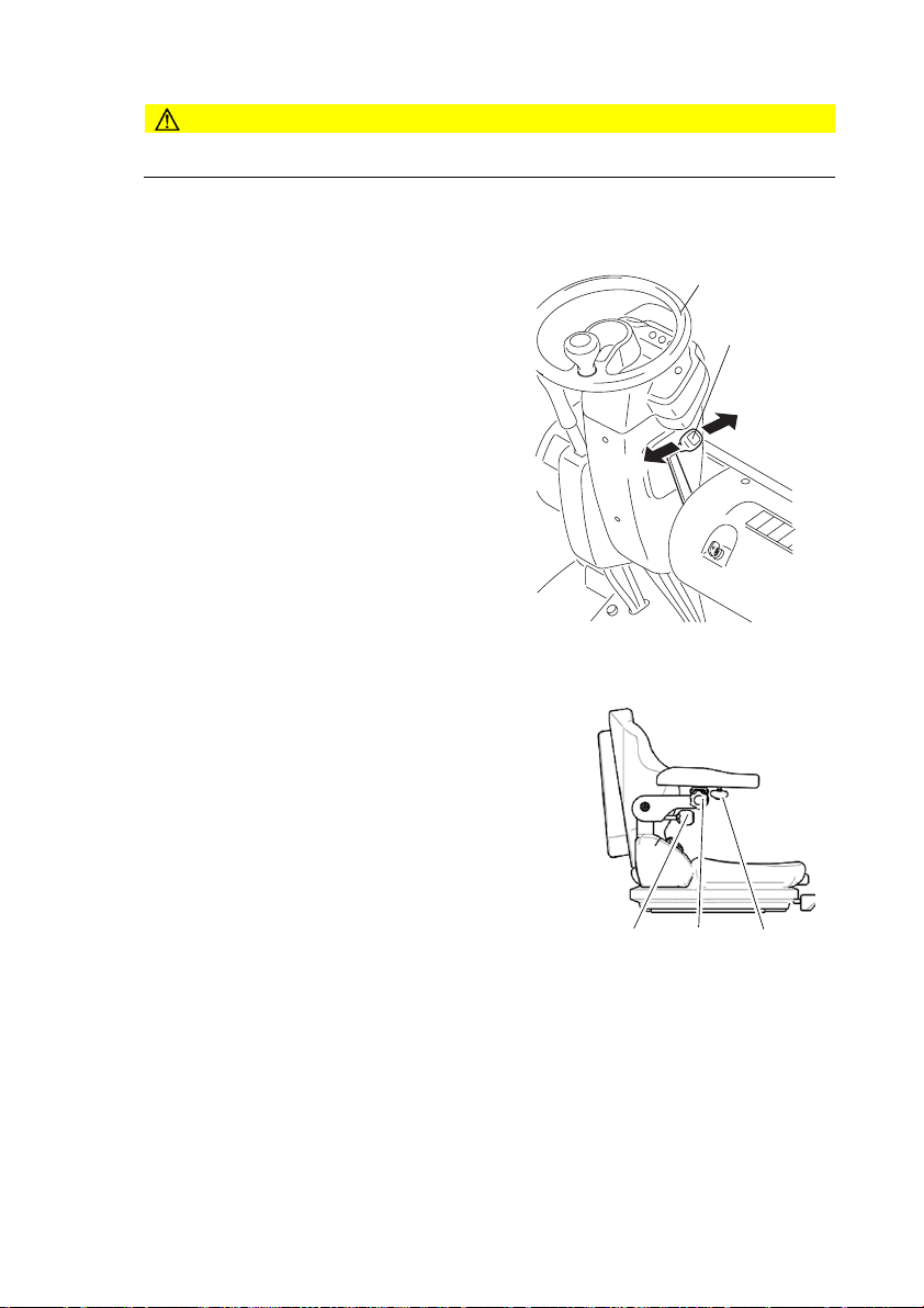
3.4.2 Adjusting the steering wheel / steering column
CAUTION!
Do not adjust the steering wheel while travelling
Individual steering wheel position
Z The tilt of the steering wheel can adjusted to suit the operator.
Procedure
• Pull the steering wheel adjusting lever
(103) in the direction of the arrow (105).
• Tilt the steering wheel (3) forward or
backward as required.
• Push the steering wheel adjusting lever
(104) in the direction of the arrow.
3.4.3 Adjusting the armrest (o)
Procedure
• Loosen the screw (106) and tilt the armrest up
or down.
• Re-tighten the screw (106).
• Loosen the screw (107) and set the armrest
vertical.
• Re-tighten the screw (107).
• Loosen the screw (108) and set the armrest
horizontal.
• Re-tighten the screw (108).
The armrest is now positioned.
3
103
104
105
106 107 108
08.11 EN
67
Page 68

3.5 Seat Belt
DANGER!
Travelling without a seat belt increases the risk of injury.
If the seat belt is not worn or is modified, personal injury can result.
XAlways put on the seat belt before starting the industrial truck.
XDo not modify the seat belt.
XDamaged or non-operational seat belts must be replaced by trained personnel.
XSeat belts must always be replaced after an accident.
XOnly original spare parts must be used for retrofits or repairs.
Z Protect the seat belt from contamination (e.g. cover it when the truck is idle) and
clean it regularly. Frozen belt locks or pulleys must be thawed out and dried to
prevent them from freezing up again.
The temperature of the warm air should not exceed +60 °C!
Starting the industrial truck on steep slopes
The automatic blocking system locks the belt in the retractor when the truck is
positioned on a steep slope. This prevents the belt from being pulled out of the
retractor.
Z Carefully drive the truck off the slope and then put on the belt.
68
08.11 EN
Page 69

4 Industrial Truck Operation
4.1 Safety regulations for truck operation
Travel routes and work areas
Only use lanes and routes specifically designated for truck traffic. Unauthorised third
parties must stay away from work areas. Loads must only be stored in places
specially designated for this purpose.
The truck must only be operated in work areas with sufficient lighting to avoid danger
to personnel and materials. Additional equipment is necessary to operate the truck in
areas of insufficient lighting.
DANGER!
Do not exceed the permissible surface and spot load limits on the travel routes.
At blind spots get a second person to assist.
The driver must ensure that the loading dock / ramp cannot move or come loose
during loading / unloading.
NOTE
Loads must not be deposited on travel or escape routes, in front of safety
mechanisms or operating equipment that must be accessible at all times.
Travel conduct
The driver must adapt the travel speed to local conditions. The truck must be driven
at slow speed when negotiating bends or narrow passageways, when passing
through swing doors and at blind spots. The driver must always observe an adequate
braking distance between the forklift truck and the vehicle in front and must be in
control of the truck at all times. Abrupt stopping (except in emergencies), rapid U turns
and overtaking at dangerous or blind spots are not permitted. Do not lean out or reach
beyond the working and operating area.
Hazardous situations
If the truck is about to tip over, do not loosen the seat belt. The driver must not jump
off the truck. The driver must lean his upper body over the steering wheel and hold
on with both hands. Tilt your body in the opposite direction of fall.
Travel visibility
The driver must look in the direction of travel and must always have a clear view of
the route ahead. Loads that affect visibility must be positioned at the rear of the truck.
If this is not possible, a second person must walk alongside the truck as a lookout to
observe the travel route while maintaining eye contact with the driver. Proceed only
at walking pace and with particular care. Stop the truck as soon as you lose eye
contact.
08.11 EN
69
Page 70

Negotiating slopes and inclines
Negotiating slopes or inclines up to 15% is only permitted if they are specifically
designed as travel routes, are clean and have a non-slip surface and providing they
can be safely travelled along in accordance with the truck's technical specifications.
The truck must always be driven with the load unit facing uphill. The industrial truck
must not be turned, operated at an angle or parked on inclines or slopes. Inclines
must only be negotiated at slow speed, with the driver ready to brake at any moment.
Particular care is required when travelling near slopes and quay walls.
Negotiating lifts and docks
Lifts may only be entered if they have sufficient capacity, are suitable for driving on
and authorised for truck traffic by the owner. The driver must satisfy himself of the
above before entering these areas. The truck must enter lifts with the load in front and
must take up a position which does not allow it to come into contact with the walls of
the lift shaft. People travelling in the lift with the forklift truck must only enter the lift
after the truck has come to a halt and must exit the lift before the truck. The driver
must ensure that the loading ramp / bridge cannot move or come loose during loading
/ unloading.
Type of loads to be carried
The operator must make sure that the load is in a satisfactory condition. Loads must
always be positioned safely and carefully. Use suitable precautions to prevent parts
of the load from tipping or falling down. Prevent liquid loads from sloshing out.
Inflammable liquids (e.g. fused metal etc.) may only be transported with suitable
auxiliary equipment. Contact your authorized Jungheinrich customer adviser.
Z For safety instructions on the nature of loads to be carried with attachments,(see
"Lifting, transporting and depositing loads" on page 82).
Towing trailers
The truck may only be used occasionally to tow trailers, (see "Towing trailers" on
page 96)
DANGER!
Exhaust emissions can be fatal
XThe truck must only be operated in well ventilated areas. If the truck is operated in
enclosed areas, this can lead to a build-up of harmful exhaust emissions, resulting
in dizziness, tiredness and even death.
XThe user must comply with legal requirements, technical standards and health and
safety regulations when operating an IC motor powered lift truck in closed rooms.
70
08.11 EN
Page 71
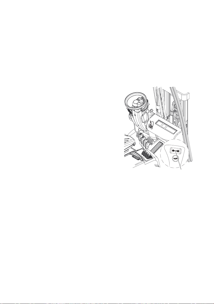
4.2 Preparing the truck for operation
Before starting the truck
Z The truck should only be operated from the driver’s seat. Do not run up the engine
in idle. The engine soon reaches operating temperature at a moderate charge and
when the speed alternates. Only fully charge the engine once it has reached
operating temperature.
Requirements
– Checks and operations to be performed before starting daily operation, (see
"Checks and operations to be performed before starting daily operation" on
page 62).
Switching on the truck
Procedure
• Apply the parking brake.
• Set the travel direction switch (70) to
neutral N. Otherwise the motor cannot be
started.
• Perform the appropriate starting procedure
depending on the type of motor; see 4.2.1
"Starting procedure for the DFG" or 4.2.2
"Starting procedure for the TFG".
70
08.11 EN
71
Page 72

4.2.1 Starting procedure for the DFG
Procedure
•
• Insert the key in the key switch (76). Set
key switch to “I”.
• The pre-heat indicator lamp (91) lights up
and goes out automatically as soon as
the required pre-heat time (approx. 4
seconds) has been reached.
• All the indicators light up briefly to test
operation.
Z All the indicators except for the engine oil
pressure display (82), parking brake
indicator (86), indicator lamp for neutral
(90) and charge current indicator (88)
should go out after a short while. If not,
stop the start-up process and rectify the
fault.
•
• Now set the ignition / starter key to the "II"
position.
Z Only apply the starter for a maximum of
15 seconds without interruption. The
Industrial truck contains a restart blocking
mechanism which prevents it from
starting again while the engine is running.
• Release the key as soon as the engine
starts. It automatically reverts to the "I"
position.
Z All indicators lights except for neutral
setting (90) and parking brake (86)
should go out as soon as the engine
starts. If not, stop the engine immediately
and rectify the fault.
The truck is now ready for operation.
76
82 86
90
0
I
II
88
91
72
08.11 EN
Page 73

4.2.2 Starting procedure for the TFG
DANGER!
Risk of escaping liquid gas if the truck does not start
XNote the safety regulations governing the handling of liquid gas
((see "Safety regulations for handling diesel fuel and LPG" on page 45))
XClose the gas bottle shut-off valve.
XSet the key switch to "O"
XNotify your superior.
Procedure
•
• Slowly open the shutoff valve on the LPG
bottle.
• Put the key in the key switch. Set key
switch to "I".
• All the indicators light up briefly to test
operation.
Z All the indicators except for the engine oil
pressure display (82), parking brake
indicator (86), indicator lamp for neutral
(90) and charge current indicator (88)
should go out after a short while. If not,
stop the start-up process and rectify the
fault.
•
• Now set the ignition / starter key to the "II"
position.
Z Only apply the starter for a maximum of
15 seconds without interruption. The
truck contains a restart blocking
mechanism which prevents it from
starting again while the engine is running.
• Release the key as soon as the engine
starts. It automatically reverts to the "I"
position.
Z All indicators lights except for neutral
setting (90) and parking brake (86)
should go out as soon as the engine
starts. If not, stop the engine immediately
and rectify the fault.
The truck is now ready for operation.
76
82 86
0
I
II
88
90
08.11 EN
73
Page 74

4.3 Parking the truck securely
DANGER!
Risk of explosion
XLPG trucks may only be parked in ground level rooms or higher and providing they
are adequately ventilated. They must not be parked near to cellar doors and entry
points, hollows, drains, drain inlets or other recesses below the parked truck.
WARNING!
An unsecured truck can cause accidents
Parking the truck on an incline, without the brakes applied or with a raised load / load
handler is dangerous and is strictly prohibited.
XAlways park the truck on a level surface. In special cases the truck may need to be
secured with wedges.
XAlways fully lower the mast and load handler.
XTilt the mast forward.
XSelect a place to park where no other people are at risk of injury from lowering
forks.
XDo not park and abandon the truck on an incline.
Parking and leaving the truck
Procedure
• Apply the parking brake, (see "Parking
brake" on page 79).
• Lower the load handler.
• Turn the key in the key switch (76) to the
“0” position.
• Remove the key from the key switch
(76).
• Close the gas bottle (TFG only).
76
Z TFG only: If the ignition key is set to “0” while the engine is running, the engine will
continue to run for a short time. This ensures that the remaining gas in the lines
between the engine and the automatic shutoff valve of the gas system is used up.
If the engine has accidentally switched off, start up the engine and switch it off again
in the correct manner at the end of the journey.
74
08.11 EN
Page 75

4.4 Emergency Disconnect
Procedure
• Move the key switch to the O position.
• Open the engine panel and remove the quick release lock from the battery pool.
This disconnects the battery from the on-board supply network and switches off all
electrical functions.
08.11 EN
75
Page 76

4.5 Travel
WARNING!
Improper travel can result in accidents
XDo not get up from the driver’s seat during travel.
XDo not drive the truck unless your are wearing a seat belt and the panels and doors
are properly locked.
XMake sure that the travel area is clear.
XAdapt the travel speed to the conditions of the route, the work area and the load.
XTilt the mast back and raise the fork carriage approx. 200 mm.
XMake sure you have enough visibility when reversing.
Travel
Requirements
– Truck prepared for operation, (see
"Preparing the truck for operation" on
page 71).
Procedure
• Release the parking brake.
• Choose the travel direction with the travel
direction switch (70).
NOTE
Only change direction when the truck has
stopped.
• To select the forward gear, push the switch
forward.
79
• To select the reverse gear, pull the switch
back.
• Raise the fork carriage approx. 200 mm.
• Tilt the mast back.
• Apply the accelerator pedal (79). The travel speed is governed by the accelerator
(79).
The truck travels in the direction selected.
Neutral locking
If the driver leaves the truck without taking it out of gear, the truck will automatically
be set to neutral. To resume travel (sitting on the truck) all controls must be
deactivated, the travel direction switch must be set to neutral “N” and then the
required direction selected.
76
70
08.11 EN
Page 77

Slow travel / brake pedal
Requirements
– Truck ready for operation, (see
"Preparing the truck for operation" on
page 71).
Procedure
• Apply the slow travel / brake pedal (72)
sensitively.
The Industrial truck moves slowly in the
selected travel direction and allows for
excellent shunting in confined areas.
Rapid lifting is possible at a slow travel
speed.
NOTE
The slow travel / brake pedal can also actuate the drum brakes but this is only
intended as a crawl speed aid. The pedal should not be used as a service brake. This
operating mode can only be used for max. 5 seconds when the engine is running at
high speed.
72
4.6 Steering
Steering
Procedure
Z Very little steering effort is required; you
should therefore turn the steering wheel
(74) sensitively.
• To negotiate a right-hand bend: Turn
the steering wheel clockwise according
to the required steering radius.
• To negotiate a left-hand bend: Turn the
steering wheel anti-clockwise according
to the required steering radius.
The truck travels in the direction selected.
08.11 EN
74
77
Page 78

4.7 Brakes
WARNING!
Accident risk
The brake pattern of the truck depends
largely on the ground conditions.
XThe driver must be aware of travel route
conditions and them into account when
braking.
XBrake with care to prevent the load from
slipping.
XAllow for increased braking distance
when travelling with an attached load.
XUse the service brake in emergencies.
4.7.1 Service brake
The brake pedal hydraulically actuates
the drum brakes of the front wheels.
When the brake pedal (78) is applied the
drum brakes are applied without
disengaging the transmission.
Applying the slow travel / brake pedal (72)
controls the flow of power in the power
shift gear. This pedal can also be used to
brake gently during crawl speed
operations.
72
78
78
08.11 EN
Page 79

4.7.2 Parking brake
DANGER!
Accident risk
XThe parking brake will hold the truck with maximum load on a clean ground surface,
on inclines of up to 15%.
XDo not park and abandon the truck on an incline.
XApplying the parking brake during travel will cause the truck to brake to a standstill.
This may cause the load to slide off the forks tines. There is a higher risk of
accidents and injury!
XWhen leaving the industrial truck, always engage the parking brake. An audible
warning will sound if the parking brake is not applied.
Z The parking brake can be used as an emergency brake.
Procedure
• Pull back the parking brake lever (73)
beyond the pressure point as far as
the stop. The parking brake is
engaged and the parking brake lever
is locked in this position.
• Press the release knob (110) and
push the parking brake lever forward
to release the parking brake.
110
73
08.11 EN
79
Page 80

4.8 Adjusting the forks
WARNING!
Trapping hazard
There is a trapping hazard when you
perform this operation.
XWear work gloves and safety shoes.
WARNING!
Unsecured and incorrectly adjusted
forks can cause accidents
Before adjusting the forks make sure the
retaining bolts (96) are fitted.
XAdjust the forks so that both forks are
equidistant from the outside edge of the
fork carriage.
XEngage the locking pin in a groove to
prevent the forks from moving
accidentally.
XThe load centre of gravity must be
located centrally between the forks.
Adjusting the forks
Requirements
– Park the truck securely, (see "Parking the
truck securely" on page 74).
Procedure
• Lift up the locking lever (111).
• Push the forks (112) into the correct position
on the fork carriage (113).
111
112
113
Z To lift the load securely, the forks (112) must
be spread as far apart as possible and
positioned centrally with respect to the fork
carriage. The load centre of gravity must be centrally aligned between the forks
(112).
• Lift the locking lever down (111) and move the forks until the locking pin engages
in a slot.
The forks are now adjusted.
96
80
08.11 EN
Page 81
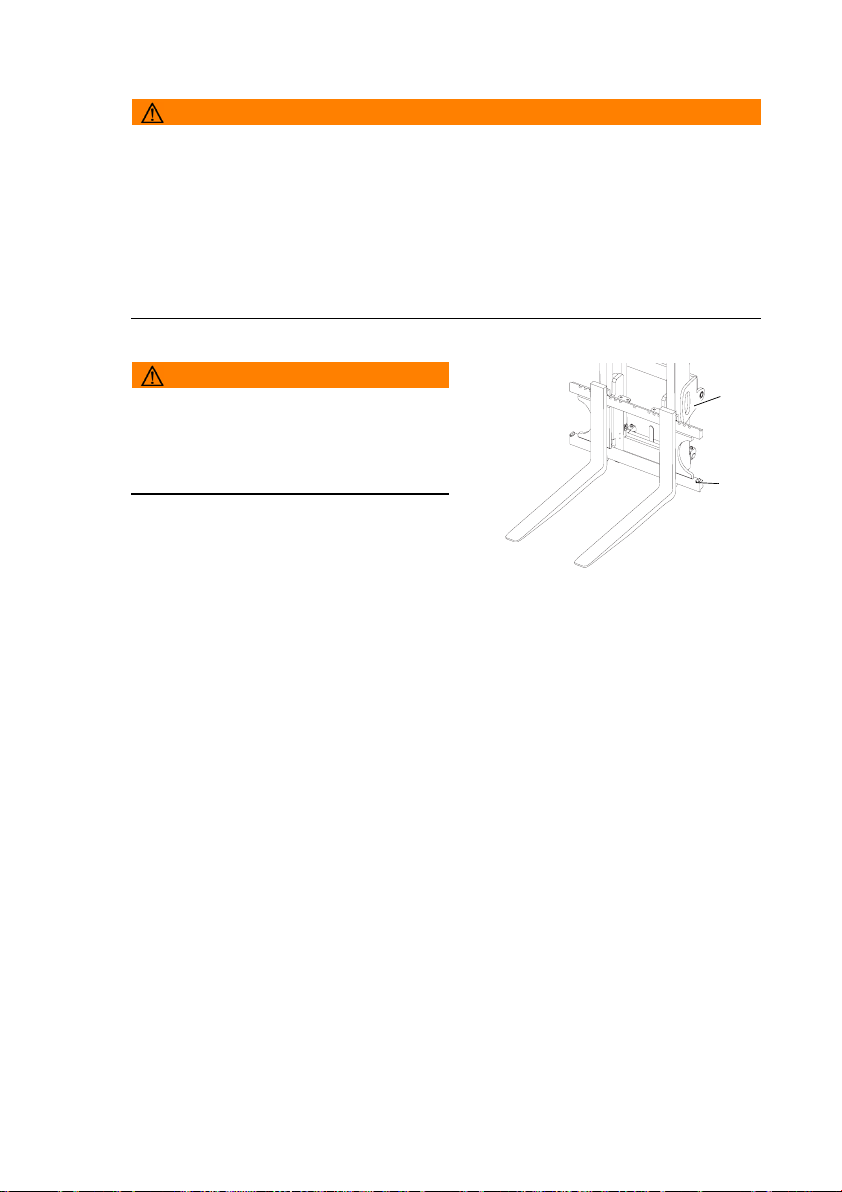
4.9 Replacing the forks
WARNING!
Unsecured forks can cause injury
You can injure your legs when replacing the forks.
XNever pull the forks towards your body.
XAlways push the forks away from your body.
XSecure heavy forks with lifting slings and a crane before pushing them down from
the fork carriage.
XAfter replacing the forks fit the retaining bolts (96) and make sure the bolts are
seated correctly. Retaining bolt torque: 85 Nm.
WARNING!
Trapping hazard
There is a trapping hazard when you
perform this operation.
XWear work gloves and safety shoes.
Replacing the forks
Requirements
– Load handler lowered and forks not touching
the ground.
Procedure
• Disassemble the retaining bolts (96).
• Loosen the fork stop (95).
• Carefully push the forks off the fork carriage.
The forks are now dismantled from the fork carriage and can be replaced.
95
96
08.11 EN
81
Page 82

4.10 Lifting, transporting and depositing loads
WARNING!
Unsecured and incorrectly positioned loads can cause accidents
Before lifting a load unit the driver must make sure that it has been correctly palletised
and does not exceed the truck’s capacity.
XInstruct other people to move out of the hazardous area of the truck. Stop working
with the truck if people do not leave the hazardous area.
XOnly carry loads that have been correctly secured and positioned. Use suitable
precautions to prevent parts of the load from tipping or falling down.
XDo not transport loads other than on the authorised load handler.
XDamaged loads must not be transported.
XIf the stacked load obscures forward visibility, then you must reverse the truck.
XMake sure you have enough visibility when reversing.
XNever exceed the maximum loads specified in the capacity chart.
XNever stand underneath a raised load handler.
XDo not stand on the load handler.
XDo not lift other people on the load handler.
XDo not reach through the mast.
XCheck the fork spread before lifting the load and adjust if necessary.
XInsert the forks as far as possible underneath the load.
Lifting load units
Requirements
– Load unit correctly palletised.
– Fork spread for the pallet checked and adjusted if necessary.
– Load unit weight matches the truck's capacity.
– Forks evenly loaded for heavy loads.
Procedure
• Drive the truck carefully up to the pallet.
• Set the mast vertical.
• Slowly insert the forks into the pallet until the fork shank touches the pallet.
• Raise the load handler.
• Reverse carefully and slowly until the load unit is outside the storage area. Make
sure you have enough clear space to reverse into.
82
08.11 EN
Page 83

NOTE
Loads must not be deposited on travel or escape routes, in front of safety
mechanisms or operating equipment that must be accessible at all times.
Transporting load units
Requirements
– Load unit correctly lifted.
– Load handler lowered for transport (approx. 150 - 200 mm above the ground).
– Mast tilted back fully.
Procedure
• Accelerate and decelerate gradually.
• Adapt your travel speed to the conditions of the route and the load you are
transporting.
• Watch out for other traffic at crossings and passageways.
• Always travel with a lookout at blind spots.
• On slopes and inclines always carry the load facing uphill, never approach at an
angle or turn.
Depositing load units
Requirements
– Warehouse location suitable for storing the load.
Procedure
• Set the mast vertical.
• Drive carefully up to the storage location.
• Carefully lower the load handler so that the forks are clear of the load.
Z Avoid depositing the load to avoid damaging the load and the load handler.
• Lower the load handler.
• Carefully remove the forks from the pallet.
The load unit is lowered.
08.11 EN
83
Page 84

4.11 Operating the lift mechanism and integrated attachments
WARNING!
Accident risk when operating the lifting device and integrated attachments
Other people can be injured in the truck's hazardous area.
The hazardous area is defined as the area in which people are at risk from the truck
movement, the load handler, attachments etc. This also includes areas which can be
reached by falling loads or lowering operating equipment.
Apart from the operator (in the normal operating position) there should be no other
people in the truck's hazardous area.
XInstruct other people to move out of the hazardous area of the truck. Stop working
with the truck if people do not leave the hazardous area.
XThe truck must be prevented from being used by unauthorised people if people do
not leave the hazardous area despite the warning.
XOnly carry loads that have been correctly secured and positioned. Use suitable
protection measure to prevent parts of the load from tipping or falling down.
XNever exceed the maximum loads specified in the capacity chart.
XNever stand underneath a raised load handler.
XDo not stand on the load handler.
XDo not lift other people on the load handler.
XDo not reach through the mast.
XThe controls should only be operated from the driver’s seat, and never suddenly.
XThe driver must be instructed in how to operate the lifting device and the
attachments.
NOTE
When the driver's seat is not occupied, the control lever is mechanically locked
in centre position.
If the driver leaves the industrial truck without moving the travel direction switch to the
neutral, the control block will remain locked in the centre position at first when the
driver returns to the driver's seat. The control lever is not released again until the
driver has moved the travel direction switch to the neutral. This safety function also
takes effect if the driver gets up off the seat for longer than 1.5 seconds without
leaving the vehicle. In this case as well the transmission must be switched once to
neutral. If the industrial truck is equipped with belt lock control (o) the belt must also
be closed again to release the control lever.
Z When the controls are released they automatically revert to neutral and the lifting
mechanism remains in the position it has reached.
When the mechanical end stop has been reach for the relevant functions (there will
be a noise from the pressure relief valve) immediately move the control lever back to
its original position.
84
08.11 EN
Page 85

Controlling the speed of the lifting
device
Moving the lever and changing the engine
speed governs the operating speed of the
hydraulic cylinders. When the levers (115,
114) are released they automatically revert
to neutral and the lifting device remains in
the position it has reached.
Procedure
• Set the travel direction switch (70) to
neutral.
• Increase the motor speed with the
accelerator pedal (79) and
• Keep moving the lever back to increase
the speed of the lifting device.
Z The engine speed does not affect the
lowering speed of the fork carriage.
114
115
70
79
08.11 EN
85
Page 86

4.11.1 Operating the lift mechanism with the SOLO PILOT
Lifting and lowering
Requirements
– To prepare the truck for operation, (see
"Preparing the truck for operation" on
page 71)
Procedure
• Pull the Solo-Pilot lever (116) in direction H to
raise the load.
• Push the Solo-Pilot lever (116)in direction S
to lower the load.
The load is now raised / lowered.
H
S
116
Z When the limit position for the operation has been reached (there will be a noise
from the pressure relief valve) release the lever. The lever will revert automatically
to neutral.
Tilting the mast forward / backward
Requirements
– To prepare the truck for operation, (see
"Preparing the truck for operation" on
page 71)
Procedure
• Pull the Solo-Pilot lever (117) in direction R to
tilt the mast back.
• Push the Solo-Pilot lever (117) in direction V
to tilt the mast forward.
The mast is now tilted back / forward.
R
117
V
Z When the limit position for the operation has been reached (there will be a noise
from the pressure relief valve) release the lever. The lever will revert automatically
to neutral.
86
08.11 EN
Page 87

Positioning the integrated sideshift (option)
Requirements
– To prepare the truck for operation, (see
"Preparing the truck for operation" on
page 71)
Procedure
• Pull the Solo-Pilot lever (118) in direction R to
move the load handler to the right (from the
driver’s viewpoint).
• Push the Solo-Pilot lever (118) in direction V
to move the load handler to the left (from the
driver’s viewpoint).
The sideshifter is now positioned.
R
118
V
Z When the limit position for the operation has been reached (there will be a noise
from the pressure relief valve) release the lever. The lever will revert automatically
to neutral.
08.11 EN
87
Page 88

Positioning the forks with an integrated fork
adjuster (option)
CAUTION!
Do not use the fork adjuster to clamp
loads.
Requirements
– Truck prepared for operation, (see "Preparing
the truck for operation" on page 71).
Procedure
• Press the toggle switch (119) and at the same time pull the Solo Pilot (120) in
direction Z: the forks will move towards each other.
• Press the toggle switch (119) and at the same time push the Solo Pilot (120) in
direction A: the forks will spread apart.
The forks are now positioned.
Z
119
A
120
Synchronising the alignment of the fork
tines with an integrated fork adjuster
(optional equipment)
Requirements
– Truck ready for operation, (see "Preparing the
truck for operation" on page 71).
– The fork tines are no longer aligned.
Procedure
• Press the toggle switch (119) and at the same
time push the SOLO-PILOT (120) in direction
A and spread the fork tines apart as far as
they will go.
• Press the toggle switch (119) and at the same time pull the SOLO-PILOT (120) in
direction Z and bring the fork tines as close to each other as they will go.
The fork tines are now synchronised.
Z
119
A
120
Z When the limit position for the operation has been reached (there will be a noise
from the pressure relief valve) release the lever. The lever will revert automatically
to neutral.
88
08.11 EN
Page 89

4.12 Safety instructions for operating additional attachments
Z Optionally, trucks can be fitted with one or more auxiliary hydraulic functions to
operate attachments. The auxiliary hydraulics are indicated with ZH1, ZH2 and
ZH3.
Auxiliary hydraulic functions for exchangeable equipment are fitted with
replacement couplings on the fork carriage. To fit exchangeable equipment (see
"Fitting additional attachments" on page 94).
DANGER!
Attaching exchangeable equipment can result in accidents.
Other people can be damaged by attaching exchangeable equipment. Use only
exchangeable equipment which has been deemed safe after a risk analysis carried
out by the owner.
XOnly use attachments with a CE mark.
XOnly use attachments that have been designed by the attachment manufacturer for
use with the respective industrial truck.
XOnly use attachments that have been fitted for the purpose by the owner.
XMake sure the operator has been instructed in the use of the attachment and that
he uses it for its correct purpose.
XRe-assess the residual capacity of the truck and if it has been altered, attach an
additional capacity plate to the truck.
XNote the attachment manufacturer’s operating instructions.
XOnly use attachments that do not restrict visibility in the travel direction.
Z If visibility in the travel direction is impaired, the owner must carry out a risk analysis
to assess whether the truck needs to be fitted with auxiliary equipment such as a
camera system or mirrors. If such equipment is used, spend sufficient time
practicing travelling with them.
08.11 EN
89
Page 90

Safety instructions for sideshifter and fork adjuster attachments
WARNING!
When using multi fork adjusters (multi pallet clamps), restricted visibility and reduced
lateral tilt resistance can result in accidents.
XAdapt the travel speeds to the visibility and load.
XMake sure you have enough visibility when reversing.
Safety instructions for clamping attachments (e.g. baling clamps, barrel
clamps, grabs etc.)
WARNING!
Falling loads can cause accidents
This can result in malfunctions and the load can fall accidentally.
XClamping attachments may only be added to trucks which have a button to enable
additional hydraulic functions.
XClamping attachments must only be operated on trucks will auxiliary hydraulics
ZH1, ZH2 or ZH3.
XWhen connecting the attachment make sure that the hydraulic lines of the
attachment are connected to the right ports, (see "Fitting additional attachments"
on page 94).
Safety instructions for rotary attachments
WARNING!
A non-centred centre of gravity can result in accidents
When using rotary devices and non-centred loads, the centre of gravity can be
displaced from the centre with a high risk of accidents.
XAdapt the travel speed to the load.
XLift the load from the centre.
Safety instructions for telescopic attachments
WARNING!
Accident risk from increased tipover hazard and reduced residual capacity
There is a greater tipover risk with extended telescopic attachments (e.g. reach
carriages, telescopic forks, telescopic crane booms).
XOnly use the telescopic function for stacking and retrieving.
XAlways retract the attachment fully during transport.
XAdapt the travel speed to changed load centre of gravity.
90
08.11 EN
Page 91

Safety instructions for attachments when transporting suspended loads
WARNING!
Swinging loads and a reduced residual capacity can result in accidents
XAdapt the travel speed to the load, less than walking pace.
XSecure swinging loads for example with lifting slings.
XReduce the residual capacity and have it certified by a expert.
Safety instructions for using loading buckets as attachments
WARNING!
Greater mast loading can cause accidents.
XWhen carrying out the daily checks and operations before starting, (see "Checks
and operations to be performed before starting daily operation" on page 62), in
particular attention check the fork carriage, mast rails and mast rollers for damage.
Safety notices for fork extensions:
WARNING!
Unsecured and excessive fork extensions can cause accidents.
XFor fork extensions with an open cross sectional area, only carry loads that are
resting along the entire length of the fork extension.
XOnly use fork extensions with the same fork cross section and minimum fork length
of the truck and which comply with the details on the fork extension data plate.
XThe basic fork length must be at least 60% of the length of the fork extension.
XLock the fork extensions onto the basic forks.
XWhen carrying out the daily checks and operations before starting, (see "Checks
and operations to be performed before starting daily operation" on page 62), also
check the fork extension lock.
XMark any fork extensions with an incomplete or faulty lock and take them out of
service.
XDo not use trucks with an incomplete or faulty fork extension lock. Replace the fork
extension.
XOnly restore the fork extension to service when the fault has been rectified.
XUse only fork extensions which have no dirt or foreign bodies near the entry
opening point. Clean the fork extensions as required.
08.11 EN
91
Page 92

4.13 Operating additional attachments for the SOLO-PILOT
WARNING!
Incorrect symbols can cause accidents
Symbols on controls that do not depict the function of the attachments can cause
accidents.
XMark the controls with symbols that indicate their function.
XSpecify the attachments’ direction of movement in accordance with ISO 3691-1 so
that they match the controls’ direction of movement.
4.13.1 Solo Pilot with control of ZH1 hydraulic port
Z Depending on the attachments used the
lever (118) is assigned the function of the
attachment. Levers that are not required are
void. For connections (see "Fitting additional
attachments" on page 94).
Procedure
• Operating the hydraulic port ZH1:
Move the lever (118) in direction V or R.
The attachment’s function is performed.
118
V
R
92
08.11 EN
Page 93

4.13.2 Solo Pilot with control of ZH1 and ZH2 hydraulic ports
Z Depending on the attachments used the lever
/ button (118, 120, 119) is assigned the
function of the attachment. Levers that are not
required are void. For connections (see
"Fitting additional attachments" on page 94).
Procedure
• Operating the hydraulic port ZH1:
Move the lever (118) in direction V or R.
• Operating the hydraulic port ZH2:
Press the toggle switch (119) and at the same
time move the lever (120) in the V or R
direction.
The attachment’s function is performed.
4.13.3 Solo Pilot with control of ZH1, ZH2 and ZH3 hydraulic ports
R
R
118
V
119
V
120
Z Functions are assigned to the levers / buttons
(118, 120, 119) depending on the
attachments used. Levers that are not
required are void. For connections (see
"Fitting additional attachments" on page 94).
Procedure
• Operating the hydraulic port ZH1:
Move the lever (118) in direction V or R.
• Operating the hydraulic port ZH2:
Move the lever (120) in direction V or R.
• Operating the hydraulic port ZH3:
Press the toggle switch (119) and at the same
time move the lever (120) in the V or R direction.
The attachment’s function is performed.
118
119
V
R
120
08.11 EN
93
Page 94
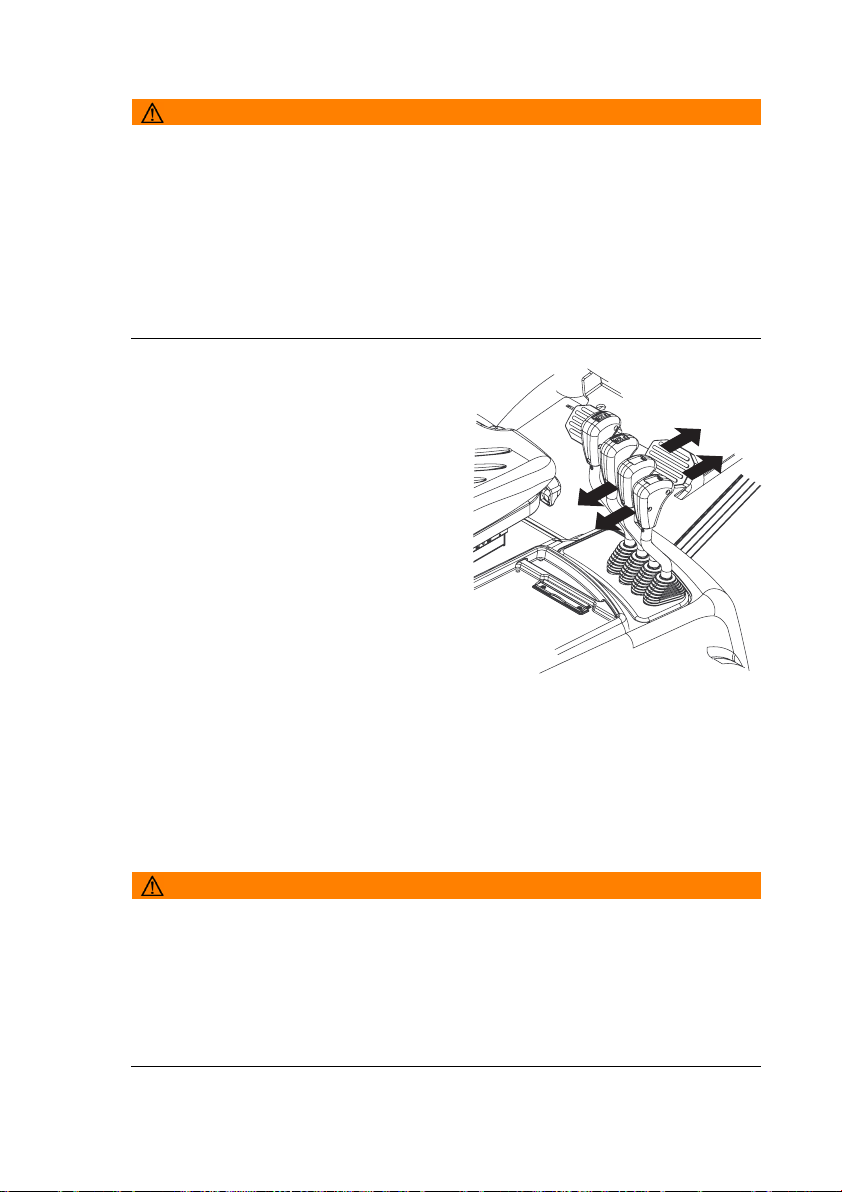
4.14 Fitting additional attachments
WARNING!
Incorrectly connected attachments can cause accidents.
Attachments with incorrectly connected hydraulic attachments can result in
accidents.
XAttachments must only be assembled and commissioned by trained, specialist
personnel.
XNote the attachment manufacturer’s operating instructions.
XBefore commissioning, check the fasteners are positioned correctly and securely
and make sure they are complete.
XBefore commissioning, make sure the attachment is working correctly.
Hydraulic ports
Requirements
– Non-pressurised hydraulic hoses.
– The exchange ports on the truck are
marked ZH2 and ZH3.
– Attachment directions of movement
defined to match the controls’ direction of
movement.
Procedure
• Lower the fork carriage to the ground.
• Turn off the ignition (set the ignition /
starter switch 0).
• Turn the ignition on again (set the ignition
/ starter switch I), but do not start the
motor.
• Move all levers as far as they will go in both directions several times. The driver's
seat must be occupied to do this. Otherwise the control lever will remain in neutral
• Attach the plug connector and engage it in position.
• Mark the controls with symbols that indicate their function.
The attachment is now hydraulically connected.
WARNING!
Hydraulic ports for clamping attachments
XClamping attachments may only be added to trucks which have a button to enable
additional hydraulic functions.
XOn trucks with auxiliary hydraulics ZH2 the clamping function should only be
attached to the coupling pair marked ZH2.
XOn trucks with auxiliary hydraulics ZH3 the clamping function should only be
attached to the coupling pair marked ZH3.
94
08.11 EN
Page 95

Z Spilled hydraulic oil must be set using a suitable agent and disposed of in
accordance with environmental regulations.
If hydraulic oil comes into contact with the skin, wash it off immediately with soap
and water. If it comes into contact with the eyes rinse them immediately with flowing
water and call for a doctor.
08.11 EN
95
Page 96

5 Towing trailers
DANGER!
Inappropriate speeds and excessive trailer loads can be dangerous
If you do not adapt your speed and / or use an excessive trailer load, the truck can
pull apart when cornering and braking.
XThe truck should only be used occasionally to tow trailers.
XThe overall weight of the trailer should not exceed the capacity indicated on the
capacity plate, (see "Identification points and data plates" on page 33). If a load is
also transported on the forks, the trailer load must be reduced by the same amount.
XDo not exceed the maximum speed of 5 km/h km/h.
XA truck must not be continually operated with trailers.
XDo not use supporting loads.
XTowing must only be performed on level, secure travel routes.
XThe owner must test trailer operation with the permissible tow load by means of a
trial run under the applicable operating conditions on site.
96
08.11 EN
Page 97

Attaching the trailer
CAUTION!
Trapping hazard
There is a trapping risk when you attach a trailer.
XFollow the instructions of the coupling manufacturer if using special trailer
couplings.
XSecure the trailer to prevent it from rolling away before coupling it.
XDo not get caught between the truck and the tiller when coupling the trailer.
XThe tiller must be horizontal, tilted down by no more than 10° and never facing up.
Attaching the trailer
Requirements
– Truck and trailer are on a level surface.
– Trailer prevented from rolling away.
Procedure
• Push the tow pin (121) down and turn it
90°.
• Pull the tow pin up and insert the tiller of
the trailer into the opening.
• Insert the tow pin, push it down, turn it
90 degrees and engage it.
The trailer is now attached to the truck.
121 122
Z To additionally ensure safe operation, the truck can be fitted with an electrical
connection for trailers with lighting.
08.11 EN
97
Page 98

6 Optional equipment
6.1 Steel cab
For trucks fitted with a steel cabin, both doors can be closed.
CAUTION!
An open door can cause accidents (123)
XDo not travel with an open door (123). When opening the door make sure there is
nobody in the door’s swing range.
XAlways close the door tightly and make sure it is locked.
XClosing the door does not release the driver from his responsibility to wear a seat
belt, (see "Seat Belt" on page 68).
Opening and closing the door
Procedure
• To unlock the cabin door turn the key anti-
clockwise.
• To lock the cabin door turn the key
clockwise.
• To open the cabin door, unlock the door and
pull out the handle (124).
123
124
98
08.11 EN
Page 99

6.2 Sliding windows
CAUTION!
An unlocked sliding window can cause accidents
XThe sliding windows must be locked at all times.
Opening and closing the windows
Procedure
• Push the lock (125) up.
• Move the window forward or back.
• Insert the lock in the stop (126).
126
125
08.11 EN
99
Page 100
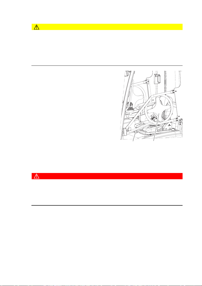
6.3 Panel door
CAUTION!
An open door can cause accidents (123)
XDo not travel with an open door (123). When opening the door make sure there is
nobody in the door’s swing range.
XAlways close the door tightly and make sure it is locked.
XClosing the door does not release the driver from his responsibility to wear a seat
belt, (see "Seat Belt" on page 68).
Hazardous situations
If the truck is about to tip over, do not loosen the
seat belt. The driver must not jump off the truck.
The driver must lean his upper body over the
steering wheel and hold on with both hands. Tilt
your body in the opposite direction of fall.
Requirements
– On trucks with a door monitoring sensor, travel
is only enabled when the panel door is closed
(o).
Procedure
• Pull the handle (127) towards the operator
position, the door swings open.
• Pull the door (123) towards the driver; the door
closes.
123127
6.4 Operator position extension
DANGER!
Altering the tilt resistance can be dangerous
The lateral tilt resistance reduces with a higher truck centre of gravity.
The height above the overhead guardincreases by 300 mm.
XAdapt the travel speed, in particular when cornering.
Z For entry and exit (see "Entry and exit" on page 63).
100
08.11 EN
 Loading...